WO2016203866A1 - 録音装置、録音システム、および、録音方法 - Google Patents
録音装置、録音システム、および、録音方法 Download PDFInfo
- Publication number
- WO2016203866A1 WO2016203866A1 PCT/JP2016/063754 JP2016063754W WO2016203866A1 WO 2016203866 A1 WO2016203866 A1 WO 2016203866A1 JP 2016063754 W JP2016063754 W JP 2016063754W WO 2016203866 A1 WO2016203866 A1 WO 2016203866A1
- Authority
- WO
- WIPO (PCT)
- Prior art keywords
- audio data
- period
- unit
- sampling rate
- predetermined
- Prior art date
- Legal status (The legal status is an assumption and is not a legal conclusion. Google has not performed a legal analysis and makes no representation as to the accuracy of the status listed.)
- Ceased
Links
Images










Classifications
-
- H—ELECTRICITY
- H04—ELECTRIC COMMUNICATION TECHNIQUE
- H04N—PICTORIAL COMMUNICATION, e.g. TELEVISION
- H04N21/00—Selective content distribution, e.g. interactive television or video on demand [VOD]
- H04N21/20—Servers specifically adapted for the distribution of content, e.g. VOD servers; Operations thereof
- H04N21/23—Processing of content or additional data; Elementary server operations; Server middleware
- H04N21/233—Processing of audio elementary streams
- H04N21/2335—Processing of audio elementary streams involving reformatting operations of audio signals, e.g. by converting from one coding standard to another
-
- G—PHYSICS
- G10—MUSICAL INSTRUMENTS; ACOUSTICS
- G10L—SPEECH ANALYSIS TECHNIQUES OR SPEECH SYNTHESIS; SPEECH RECOGNITION; SPEECH OR VOICE PROCESSING TECHNIQUES; SPEECH OR AUDIO CODING OR DECODING
- G10L19/00—Speech or audio signals analysis-synthesis techniques for redundancy reduction, e.g. in vocoders; Coding or decoding of speech or audio signals, using source filter models or psychoacoustic analysis
- G10L19/02—Speech or audio signals analysis-synthesis techniques for redundancy reduction, e.g. in vocoders; Coding or decoding of speech or audio signals, using source filter models or psychoacoustic analysis using spectral analysis, e.g. transform vocoders or subband vocoders
-
- G—PHYSICS
- G10—MUSICAL INSTRUMENTS; ACOUSTICS
- G10L—SPEECH ANALYSIS TECHNIQUES OR SPEECH SYNTHESIS; SPEECH RECOGNITION; SPEECH OR VOICE PROCESSING TECHNIQUES; SPEECH OR AUDIO CODING OR DECODING
- G10L21/00—Speech or voice signal processing techniques to produce another audible or non-audible signal, e.g. visual or tactile, in order to modify its quality or its intelligibility
- G10L21/04—Time compression or expansion
-
- H—ELECTRICITY
- H03—ELECTRONIC CIRCUITRY
- H03M—CODING; DECODING; CODE CONVERSION IN GENERAL
- H03M1/00—Analogue/digital conversion; Digital/analogue conversion
- H03M1/06—Continuously compensating for, or preventing, undesired influence of physical parameters
-
- H—ELECTRICITY
- H04—ELECTRIC COMMUNICATION TECHNIQUE
- H04N—PICTORIAL COMMUNICATION, e.g. TELEVISION
- H04N21/00—Selective content distribution, e.g. interactive television or video on demand [VOD]
- H04N21/20—Servers specifically adapted for the distribution of content, e.g. VOD servers; Operations thereof
- H04N21/23—Processing of content or additional data; Elementary server operations; Server middleware
- H04N21/233—Processing of audio elementary streams
-
- H—ELECTRICITY
- H04—ELECTRIC COMMUNICATION TECHNIQUE
- H04N—PICTORIAL COMMUNICATION, e.g. TELEVISION
- H04N21/00—Selective content distribution, e.g. interactive television or video on demand [VOD]
- H04N21/40—Client devices specifically adapted for the reception of or interaction with content, e.g. set-top-box [STB]; Operations thereof
- H04N21/41—Structure of client; Structure of client peripherals
- H04N21/422—Input-only peripherals, i.e. input devices connected to specially adapted client devices, e.g. global positioning system [GPS]
- H04N21/42203—Input-only peripherals, i.e. input devices connected to specially adapted client devices, e.g. global positioning system [GPS] sound input device, e.g. microphone
-
- H—ELECTRICITY
- H04—ELECTRIC COMMUNICATION TECHNIQUE
- H04N—PICTORIAL COMMUNICATION, e.g. TELEVISION
- H04N21/00—Selective content distribution, e.g. interactive television or video on demand [VOD]
- H04N21/40—Client devices specifically adapted for the reception of or interaction with content, e.g. set-top-box [STB]; Operations thereof
- H04N21/41—Structure of client; Structure of client peripherals
- H04N21/422—Input-only peripherals, i.e. input devices connected to specially adapted client devices, e.g. global positioning system [GPS]
- H04N21/4223—Cameras
-
- H—ELECTRICITY
- H04—ELECTRIC COMMUNICATION TECHNIQUE
- H04N—PICTORIAL COMMUNICATION, e.g. TELEVISION
- H04N21/00—Selective content distribution, e.g. interactive television or video on demand [VOD]
- H04N21/40—Client devices specifically adapted for the reception of or interaction with content, e.g. set-top-box [STB]; Operations thereof
- H04N21/43—Processing of content or additional data, e.g. demultiplexing additional data from a digital video stream; Elementary client operations, e.g. monitoring of home network or synchronising decoder's clock; Client middleware
- H04N21/439—Processing of audio elementary streams
- H04N21/4398—Processing of audio elementary streams involving reformatting operations of audio signals
-
- H—ELECTRICITY
- H04—ELECTRIC COMMUNICATION TECHNIQUE
- H04N—PICTORIAL COMMUNICATION, e.g. TELEVISION
- H04N21/00—Selective content distribution, e.g. interactive television or video on demand [VOD]
- H04N21/80—Generation or processing of content or additional data by content creator independently of the distribution process; Content per se
- H04N21/85—Assembly of content; Generation of multimedia applications
- H04N21/854—Content authoring
- H04N21/85406—Content authoring involving a specific file format, e.g. MP4 format
-
- H—ELECTRICITY
- H04—ELECTRIC COMMUNICATION TECHNIQUE
- H04N—PICTORIAL COMMUNICATION, e.g. TELEVISION
- H04N21/00—Selective content distribution, e.g. interactive television or video on demand [VOD]
- H04N21/80—Generation or processing of content or additional data by content creator independently of the distribution process; Content per se
- H04N21/85—Assembly of content; Generation of multimedia applications
- H04N21/854—Content authoring
- H04N21/8547—Content authoring involving timestamps for synchronizing content
-
- H—ELECTRICITY
- H04—ELECTRIC COMMUNICATION TECHNIQUE
- H04N—PICTORIAL COMMUNICATION, e.g. TELEVISION
- H04N5/00—Details of television systems
- H04N5/76—Television signal recording
-
- H—ELECTRICITY
- H04—ELECTRIC COMMUNICATION TECHNIQUE
- H04N—PICTORIAL COMMUNICATION, e.g. TELEVISION
- H04N5/00—Details of television systems
- H04N5/76—Television signal recording
- H04N5/91—Television signal processing therefor
-
- H—ELECTRICITY
- H04—ELECTRIC COMMUNICATION TECHNIQUE
- H04N—PICTORIAL COMMUNICATION, e.g. TELEVISION
- H04N9/00—Details of colour television systems
- H04N9/79—Processing of colour television signals in connection with recording
- H04N9/80—Transformation of the television signal for recording, e.g. modulation, frequency changing; Inverse transformation for playback
- H04N9/802—Transformation of the television signal for recording, e.g. modulation, frequency changing; Inverse transformation for playback involving processing of the sound signal
-
- H—ELECTRICITY
- H04—ELECTRIC COMMUNICATION TECHNIQUE
- H04N—PICTORIAL COMMUNICATION, e.g. TELEVISION
- H04N9/00—Details of colour television systems
- H04N9/79—Processing of colour television signals in connection with recording
- H04N9/80—Transformation of the television signal for recording, e.g. modulation, frequency changing; Inverse transformation for playback
- H04N9/82—Transformation of the television signal for recording, e.g. modulation, frequency changing; Inverse transformation for playback the individual colour picture signal components being recorded simultaneously only
- H04N9/8205—Transformation of the television signal for recording, e.g. modulation, frequency changing; Inverse transformation for playback the individual colour picture signal components being recorded simultaneously only involving the multiplexing of an additional signal and the colour video signal
-
- H—ELECTRICITY
- H03—ELECTRONIC CIRCUITRY
- H03H—IMPEDANCE NETWORKS, e.g. RESONANT CIRCUITS; RESONATORS
- H03H17/00—Networks using digital techniques
- H03H17/02—Frequency selective networks
- H03H17/06—Non-recursive filters
- H03H17/0621—Non-recursive filters with input-sampling frequency and output-delivery frequency which differ, e.g. extrapolation; Anti-aliasing
- H03H17/0628—Non-recursive filters with input-sampling frequency and output-delivery frequency which differ, e.g. extrapolation; Anti-aliasing the input and output signals being derived from two separate clocks, i.e. asynchronous sample rate conversion
-
- H—ELECTRICITY
- H03—ELECTRONIC CIRCUITRY
- H03H—IMPEDANCE NETWORKS, e.g. RESONANT CIRCUITS; RESONATORS
- H03H17/00—Networks using digital techniques
- H03H17/02—Frequency selective networks
- H03H17/06—Non-recursive filters
- H03H17/0621—Non-recursive filters with input-sampling frequency and output-delivery frequency which differ, e.g. extrapolation; Anti-aliasing
- H03H17/0635—Non-recursive filters with input-sampling frequency and output-delivery frequency which differ, e.g. extrapolation; Anti-aliasing characterized by the ratio between the input-sampling and output-delivery frequencies
- H03H17/0685—Non-recursive filters with input-sampling frequency and output-delivery frequency which differ, e.g. extrapolation; Anti-aliasing characterized by the ratio between the input-sampling and output-delivery frequencies the ratio being rational
Definitions
- This technology relates to a recording device, a recording system, and a recording method.
- the present invention relates to a recording device, a recording system, and a recording method for changing the reproduction time of audio data.
- the sound quality is degraded as the sound reproduction time is increased.
- the playback time is doubled, the audio frequency is reduced to 1 ⁇ 2 and the pitch is reduced by about one octave compared to the case where the playback time is not extended.
- the difference in sound quality between the portion where the reproduction time is extended and the portion where the reproduction time is not extended becomes large, and a sense of incongruity occurs, and the reproduction quality of the entire sound is lowered.
- This technology has been created in view of such a situation, and aims to suppress deterioration in sound quality in an apparatus that records voice and extends playback time.
- the present technology has been made in order to solve the above-described problems.
- the first aspect of the present technology is to sample audio within a predetermined period at a sampling rate higher than a predetermined sampling rate and to convert the audio data to high resolution.
- a sampling processing unit that performs processing to generate audio data and processing to generate audio data as normal audio data by sampling audio outside the predetermined period at the predetermined sampling rate, and a reproduction time of the high-resolution audio data are a recording device and a recording method. This brings about the effect that the reproduction time of high-resolution audio data sampled within a predetermined period at a sampling rate higher than the predetermined sampling rate is extended.
- the sampling processing unit samples the sound at the predetermined sampling rate outside the predetermined period, and samples at a sampling rate higher than the predetermined sampling rate within the predetermined period.
- the audio may be sampled by switching the rate. This brings about the effect that the sampling rate is switched within the predetermined period.
- the sampling processing unit samples the audio at a sampling rate higher than the predetermined sampling rate to generate the high-resolution audio data, and outside the predetermined period.
- a sampling rate converter that resamples the high-resolution audio data at the predetermined sampling rate to generate the normal audio data. This brings about the effect that normal audio data is generated by resampling of high-resolution audio data.
- the sampling processing unit samples the audio at a sampling rate higher than the predetermined sampling rate and generates the high-resolution audio data, and the sampling at the predetermined sampling rate.
- a normal microphone for sampling the sound to generate the normal sound data, and selecting and outputting the high-resolution sound data within the predetermined period, and selecting and outputting the normal sound data outside the predetermined period And a selection unit. As a result, the high-resolution audio data is selected within a predetermined period, and the normal audio data is selected outside the predetermined period.
- the selection unit may perform a synthesis process for synthesizing the normal audio data with the high-resolution audio data in a certain fade period within the predetermined period. This brings about the effect that the normal audio data is synthesized with the high resolution audio data in a certain fade period.
- the selection unit may change the ratio of the high-resolution audio data every time a unit time shorter than the fade period elapses in the synthesis process. This brings about the effect that the ratio of the high-resolution audio data is changed every time the unit time elapses.
- an imaging unit that captures a plurality of frames at a frame rate higher than a predetermined frame rate, and a frame rate of a frame captured outside the predetermined period among the plurality of frames is set to the predetermined rate.
- a frame rate conversion unit for converting the frame rate to the above-described frame rate. This brings about the effect that the frame rates of a plurality of frames imaged outside the predetermined period at a frame rate higher than the predetermined frame rate are converted to the predetermined frame rate.
- a control unit that sets a period including a predetermined timing as the predetermined period may be further provided. This brings about the effect that a period including a predetermined timing is set as the predetermined period.
- the image processing apparatus further includes a scene change detection unit that detects a scene change timing at which a scene has changed from the plurality of frames, and the control unit sets a period including the scene change timing to the predetermined period. It may be set as the period. This brings about the effect that the period including the scene change timing is set as the predetermined period.
- the senor may further include a sensor that detects a predetermined detection target, and the control unit may set a period including a timing at which the detection target is detected as the predetermined period. This brings about the effect
- a signal processing unit that performs predetermined signal processing on the high-resolution audio data with the reproduction time extended may be further provided. This brings about the effect that predetermined signal processing is performed on the high-resolution audio data.
- the signal processing unit may duplicate the high-resolution audio data. This brings about the effect that the high-resolution audio data is duplicated.
- the signal processing unit may adjust the volume level of the high-resolution audio data with a predetermined gain. This brings about the effect that the volume level of the high-resolution audio data is adjusted by a predetermined gain.
- the signal processing unit may change the frequency characteristics of the high-resolution audio data. This brings about the effect that the frequency characteristics of the high-resolution audio data are changed.
- a recording device that generates metadata including setting information indicating signal processing to be performed, and the high-resolution audio data and the normal audio data that have been subjected to the signal processing by executing the signal processing in accordance with the setting information are reproduced.
- a recording system including a playback device. As a result, the high-resolution audio data is selected within a predetermined period, and the normal audio data is selected outside the predetermined period.
- the format of the metadata is MPEG4-AAC
- the recording device may record the setting information in a DSE (Data Stream Element) area of the metadata.
- DSE Data Stream Element
- the format of the metadata may be MPEG4-system
- the recording device may record the setting information in the udta area of the metadata.
- the setting information is recorded in the udta area.
- the format of the metadata is HMMP (Home and Mobile Multimedia Platform), and the recording device may record the setting information in the uid area of the metadata. As a result, the setting information is recorded in the uuid area.
- HMMP Home and Mobile Multimedia Platform
- the recording system includes a recording device that generates metadata including setting information indicating signal processing to be performed, and an editing device that changes the setting information and executes the signal processing indicated by the changed setting information.
- 1 is a block diagram illustrating a configuration example of an imaging apparatus according to a first embodiment. It is a block diagram which shows the example of 1 structure of the moving image taking part in 1st Embodiment. It is a block diagram which shows one structural example of the audio
- First embodiment (example of extending the playback time of high-resolution audio data) 2.
- Second Embodiment (Example in which signal processing is performed by extending the reproduction time of high-resolution audio data) 3.
- Third Embodiment (Example of generating metadata by extending the playback time of high-resolution audio data) 4).
- Fourth Embodiment (Example in which metadata is edited by extending the playback time of high-resolution audio data) 5.
- Fifth Embodiment (Example of extending the playback time of high resolution audio data and converting the sampling rate of high resolution audio data) 6).
- Sixth Embodiment (Example in which normal audio data is synthesized with high resolution audio data and the reproduction time is extended)
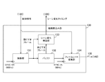
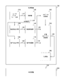
- FIG. 1 is a block diagram illustrating a configuration example of the imaging apparatus 100 according to the first embodiment.
- the imaging device 100 is a device that performs recording and recording, and includes a user interface unit 110, a control unit 120, a moving image capturing unit 130, a moving image processing unit 140, a recording format converting unit 150, an audio capturing unit 160, an audio processing unit 170, and the like.
- a recording unit 180 is provided.
- the imaging device 100 is an example of a recording device described in the claims.
- the user interface unit 110 generates an operation signal according to a user operation.
- the user interface unit 110 supplies the generated operation signal to the control unit 120.
- the control unit 120 controls the entire imaging apparatus 100 according to the operation signal.
- the control unit 120 generates a control signal for controlling the recording and recording operation according to the operation signal.
- This control signal includes, for example, a signal for instructing recording and recording start timing and end timing thereof. It is assumed that the recording start timing is the same as the recording start timing. Similarly, it is assumed that recording and recording end timing are the same timing.
- the control signal further includes a signal for instructing start timing and end timing of the high frame rate period.
- the high frame rate period is a period during which imaging is performed at a higher frame rate than during reproduction. For example, a period of a certain length (such as 1 second) around the timing when the user presses a predetermined button is set as the high frame rate period.
- the frame rate outside the high frame rate period is the same as that during reproduction.
- the frame rate outside the high frame period (during reproduction) is set to 60 hertz (Hz), for example, and the frame rate within the high frame rate period is set to 600 hertz (Hz), for example.
- the frame rate at the time of reproduction is not limited to 60 hertz (Hz), and may be 30 hertz (Hz). Further, the frame rate within the high frame rate period is not limited to 600 hertz (Hz) as long as the value is higher than that during reproduction, and may be 120 hertz (Hz).
- the control unit 120 supplies control signals indicating the above-described timings to the moving image capturing unit 130, the sound capturing unit 160, and the sound processing unit 170 via the signal line 129.
- the moving image capturing unit 130 sequentially captures a plurality of video frames according to the control signal.
- the moving image capturing unit 130 supplies moving image data including the captured video frames in time series order to the moving image processing unit 140 via the signal line 139.
- the moving image processing unit 140 performs processing for encoding moving image data.
- This moving image data is encoded in accordance with, for example, MPEG (Moving Picture Picture Experts Group) -2 standard.
- the moving image processing unit 140 packetizes the encoded moving image data into a video packet and supplies it to the recording format conversion unit 150 via the signal line 149.
- the moving image processing unit 140 may perform encoding according to a standard other than MPEG-2, such as MPEG-4.
- the sound capturing unit 160 samples sound according to the control signal and generates sound data.
- the sound capturing unit 160 samples sound at a predetermined sampling rate, and quantizes the sound volume level into digital sound data each time sampling is performed.
- a method of AD (Analog-to-Digital) conversion of an analog signal by sampling and quantization is called a PCM (Pulse Code Modulation) method.
- the audio capturing unit 160 samples the audio at a higher sampling rate within the high frame rate period than at the outside of the high frame period.
- the sampling rate within the high frame rate period is set to 96 kilohertz (kHz), for example, and the sampling rate outside the high frame rate period is set to 48 kilohertz (kHz), for example.
- audio data sampled within the high frame rate period is referred to as “high-resolution audio data”, and audio data sampled outside the high frame rate period is referred to as “normal audio data”.
- the sound capturing unit 160 supplies these sound data to the sound processing unit 170 via the signal line 169.
- the voice capturing unit 160 is an example of a sampling processing unit described in the claims.
- the sampling rate outside the high frame rate period is not limited to 48 kilohertz (kHz) as long as it is lower than that within the high frame rate period, and may be 44.1 kilohertz (kHz).
- the sampling rate within the high frame rate period is not limited to 96 kilohertz (kHz) as long as it is higher than that outside the high frame rate period, and may be 192 kilohertz (kHz).
- the audio processing unit 170 extends the reproduction time of the high-resolution audio data at a constant magnification (for example, 2 times) according to the control signal.
- the audio processing unit 170 encodes high-resolution audio data whose reproduction time is extended and normal audio data in a predetermined encoding unit. These audio data are encoded, for example, in units of 20 milliseconds (ms) according to the MPEG standard.
- Each audio signal encoded in the encoding unit is called an “audio frame”.
- the audio processing unit 170 packetizes the audio frame into an audio packet and supplies it to the recording format conversion unit 150 via the signal line 179.
- the recording format conversion unit 150 converts the recording format of video packets and audio packets into a predetermined format.
- the recording format conversion unit 150 sets a playback time for each of the audio frame and the video frame.
- PTS Presentation Time Time Stamp
- the PTS of the video frame is set at the same interval (for example, 1/60 seconds) as the imaging interval of the video frame outside the high frame rate period.
- the PTS of the first audio frame generated from the high-resolution audio data is set at a predetermined timing (such as a start time or an intermediate time) within a slow playback period obtained by extending the high frame rate period.
- the recording format converter 150 supplies the data including the packets after the format conversion as a stream to the recording unit 180 via the signal line 159, and records the stream.
- the circuits such as the moving image capturing unit 130, the moving image processing unit 140, the audio capturing unit 160, and the audio processing unit 170 are provided in one device, they may be distributed and provided in a plurality of devices. For example, only a circuit for recording (such as a moving image capturing unit 130 and a moving image processing unit 140) is provided in the imaging device 100, and a circuit for recording (such as a sound capturing unit 160 and a sound processing unit 170) is provided in the recording device. It may be provided.
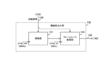
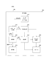
- FIG. 2 is a block diagram illustrating a configuration example of the moving image capturing unit 130 according to the first embodiment.
- the moving image capturing unit 130 includes an imaging unit 131 and a frame rate conversion unit 134.
- the imaging unit 131 images a plurality of video frames in time series in synchronization with a predetermined vertical synchronization signal SYNC_VH according to the operation signal.
- the imaging unit 131 includes, for example, an optical system such as an imaging lens and an imaging element.
- an imaging device for example, a CMOS (Complementary Metal Oxide Semiconductor) sensor or a CCD (Charge Coupled Device) sensor is used.
- the frequency of the vertical synchronization signal SYNC_VH is a value higher than the frame rate at the time of reproduction, for example, 600 hertz (Hz).
- the imaging unit 131 performs imaging over a period from the recording start timing to the end timing indicated by the control signal, and supplies each of the video frames to the frame rate conversion unit 134.
- the frame rate conversion unit 134 converts the frame rate according to the control signal.
- the frame rate conversion unit 134 converts the frame rate of the video frame imaged in the high frame rate period indicated by the control signal into a frame rate of the frequency (for example, 60 Hz: Hz) of the vertical synchronization signal SYNC_VL.
- the frame rate is converted by a process of thinning out video frames every predetermined number.
- the frame rate of a video frame captured outside the high frame rate period is not converted.
- the frame rate conversion unit 134 supplies the moving image data including these video frames to the moving image processing unit 140.
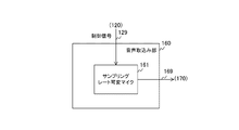
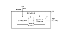
- FIG. 3 is a block diagram illustrating a configuration example of the voice capturing unit 160 according to the first embodiment.
- the audio capturing unit 160 includes a sampling rate variable microphone 161.
- the sampling rate variable microphone 161 changes the sampling rate according to the control signal and samples the sound.
- This variable sampling rate microphone 161 samples audio at a constant sampling rate (for example, 48 kilohertz) outside the high frame rate period indicated by the control signal.
- the sampling rate variable microphone 161 within the high frame rate period switches the sampling rate to a higher value (for example, 96 kHz) than outside the high frame rate period and samples the sound.
- the sampling rate variable microphone 161 supplies the normal audio data sampled outside the high frame rate period and the high resolution audio data sampled within the high frame rate period to the audio processing unit 170.
- sampling rate variable microphone 161 an analog microphone that outputs an analog audio signal may be provided instead of this digital microphone.
- an AD converter that AD converts the audio signal from the analog microphone is further provided, and the AD converter performs sampling by switching the sampling rate.
- the voice capturing unit 160 may switch gradually in steps when switching the sampling frequency (sampling rate). For example, the voice capturing unit 160 gradually increases the sampling rate over a certain period from the start of the high frame rate period. In addition, the audio capturing unit 160 slightly decreases the sampling rate over a period from a point in time before the end of the high frame rate period to the end point. Thereby, the uncomfortable feeling at the part where the sampling rate is switched can be reduced.
- FIG. 4 is a block diagram illustrating a configuration example of the audio processing unit 170 according to the first embodiment.
- the audio processing unit 170 includes a buffer 171, a reproduction time conversion unit 172, and an audio encoding unit 177.
- the buffer 171 holds a certain amount of audio data.
- the playback time conversion unit 172 converts the playback time of high-resolution audio data.
- the reproduction time conversion unit 172 reads out the audio data sampled within the high frame rate period indicated by the control signal (that is, high resolution audio data) from the buffer 171 and expands the reproduction time at a constant magnification to generate the audio code. To the conversion unit 177.
- audio data sampled outside the high frame rate period is supplied to the audio encoding unit 177 as it is without changing the reproduction time.
- the audio encoding unit 177 encodes audio data into an audio frame.
- the voice encoding unit 177 packetizes the audio frame into an audio packet and supplies it to the recording format conversion unit 150 via the signal line 179.
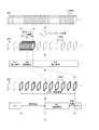
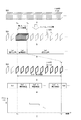
- FIG. 5 is a diagram illustrating an example of a stream according to the first embodiment.
- a is a figure which shows an example of the video frame image
- the frequency of the vertical synchronization signal SYNC_VH is 600 hertz (Hz)
- a plurality of video frames are captured every 1/600 seconds.
- FIG. 5 is a diagram illustrating an example of a frame after frame rate conversion.
- a high frame rate period is set in accordance with a user operation, and the frame rate is converted to a low frame rate of, for example, 60 hertz (Hz) outside the high frame rate period.
- a video frame surrounded by a bold line c in the figure indicates a video frame within a high frame rate period.
- audio data Sa1, Sa2, and Sa3 are generated in order by sampling.
- the audio data Sa1 is normal audio data sampled at a relatively low sampling rate (for example, 48 kilohertz) before the start timing Ts of the high frame rate period.
- the audio data Sa2 is high-resolution audio data sampled at a relatively high sampling rate (for example, 96 kilohertz) over a high frame rate period.
- the audio data Sa3 is normal audio data sampled at a relatively low sampling rate after the end timing Te of the high frame rate period.
- D in FIG. 5 shows an example of a video frame in which the playback time is set.
- a playback time for playback at a low frame rate of 60 hertz (Hz) is set.
- the moving object imaged in the high frame rate period is reproduced with a very slow movement.
- the frame rate in the high frame rate period is 600 hertz (Hz) and the frame rate at the time of playback is 60 hertz (Hz)
- the slow playback period is stretched to 10 times the high frame rate period.
- the operating speed is reduced to 1/10.
- E in FIG. 5 is a diagram illustrating an example of the audio data after the reproduction time conversion.
- the audio processing unit 170 extends the reproduction time of the high resolution audio data (Sa2) to generate audio data Sa2 ′.
- the reproduction time of the audio data Sa2 ′ is set, for example, at an intermediate time Tc ′ of the slow reproduction period.
- the playback time of the converted audio data Sa2 ′ is not limited to the intermediate time Tc ′ of the slow playback period, and may be, for example, the start timing Ts of the slow playback period. If there is a continuous silent period immediately before the start timing Ts of the slow playback period, the imaging apparatus 100 may set the start timing of the period as the playback time of the audio data Sa2 ′.
- FIG. 6 is a diagram illustrating an example of high-resolution audio data before and after conversion of the reproduction time according to the first embodiment.
- a is a figure which shows an example of the high resolution audio
- b in the figure is a figure which shows an example of the high resolution audio
- the vertical axis indicates the volume level and the horizontal axis indicates time.
- a dotted line indicates a waveform of an analog audio signal restored when the audio data is converted from digital to analog (DA).
- DA digital to analog
- audio data such as audio data 502 and 504 is sampled at a relatively high sampling rate in the high frame rate period.
- the sampling rate is 96 kilohertz (kHz)
- 96 ⁇ 1000 pieces of audio data are generated per second.
- the number of quantization bits is 24 bits
- the data amount per second of monaural audio data is 96 ⁇ 1000 ⁇ 24 bits.
- the number of quantization bits is not limited to 24 bits, and may be 16 bits.
- data such as audio data 503 is interpolated between audio data (502 and 504) before conversion.
- the hatched portion in the figure shows the interpolated audio data.
- the audio processing unit 170 interpolates, as the audio data 503, data indicating a volume level intermediate between the volume levels of the adjacent audio data 502 and 504.
- the reproduction time of the audio data is extended. For example, when the number of audio data is doubled by interpolation, the reproduction time is doubled.
- the process of extending the reproduction time is called time stretching or speech speed conversion.
- the maximum frequency of analog audio that can be restored by the sampled audio data is half the sampling frequency fs according to the sampling theorem.
- the half value (fs / 2) of this sampling frequency is called the Nyquist frequency.
- This Nyquist frequency (a frequency that can be restored) is lowered by extending the reproduction time. For example, when the reproduction time is doubled, the Nyquist frequency is reduced to half.
- the audio processing unit 170 performs time stretching by the process of stretching the waveform as it is, but is not limited to this method as long as the reproduction time can be extended.
- the sound processing unit 170 may extend the reproduction time by dividing the sound waveform into a plurality of parts and copying and inserting a part of them. According to this processing, it is possible to extend the reproduction time with almost no change in frequency. Even in this case, since the sound quality is slightly deteriorated at the part where the reproduction time is converted, the sound quality deterioration can be suppressed by recording the high-resolution audio data.
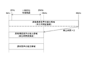
- FIG. 7 is a diagram illustrating an example of a restoration band of audio data according to the first embodiment.
- the sampling rate of high-resolution audio data is 96 kilohertz (kHz)
- the sampling rate of normal audio data is 48 kilohertz (kHz).
- the frequency band of audio restored by DA conversion of high-resolution audio data (hereinafter referred to as “restoration band”) is 0 according to the sampling theorem before the reproduction time is converted.
- restoration band the frequency band of audio restored by DA conversion of high-resolution audio data
- the restoration band is half that before the expansion, that is, 0 to 24 kilohertz (kHz).
- the restoration band of normal audio data is 0 to 24 kilohertz (kHz) according to the sampling theorem.
- the general human audible range is 20 hertz (Hz) to 20 kilohertz (kHz), which is narrower than the restoration band after changing the playback time. Therefore, even if the playback time is changed, the user does not feel a decrease in sound quality. Further, since the restoration band of the high-resolution audio data after changing the reproduction time is the same as that of the normal audio data, the sound quality in the slow reproduction period in which the reproduction time is extended is not different from the period in which the reproduction time is not extended.
- the apparatus described in Patent Document 1 records without changing the sampling rate even during a high frame rate period.
- the playback time of the audio data sampled during the high frame rate period is extended, the restoration band becomes narrower and the sound quality deteriorates compared to the period when the audio data is not extended.
- the normal audio data sampling rate is preferably higher than twice the maximum frequency (approximately 20 kHz) in the audible range.
- the sampling rate of the high resolution audio data is preferably higher than a value obtained by multiplying twice the maximum frequency of the audible range by a magnification (such as twice) for the reproduction time.
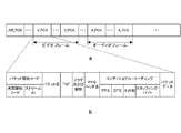
- FIG. 8 is a diagram illustrating an example of a data structure of a stream and a packet according to the first embodiment.
- a is a figure which shows an example of the data structure of a stream.
- a stream includes, for example, a packet ARI_PCK including auxiliary data, a video packet V_PCK, and an audio packet A_PCK.
- a video frame is stored in one or more video packets V_PCK
- an audio frame is stored in one or more audio packets A_PCK.
- FIG. 8 is a diagram illustrating an example of a data structure of the video packet V_PCK.
- the video packet V_PCK stores a packet start code, a packet length, a code of “10”, a flag and control, a PES header length, a conditional coding, and packet data.
- the data structure of the audio packet is the same as that of the video packet.
- a head start code indicating the head of the packet and a stream ID for identifying the stream are stored.
- a PTS indicating the reproduction time
- a DTS Decoding Time Stamp
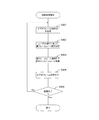
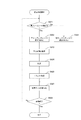
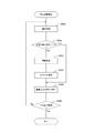
- FIG. 9 is a flowchart illustrating an example of a recording process according to the first embodiment.
- This recording process starts, for example, when an operation for starting recording (such as pressing a recording button) is performed.
- the imaging apparatus 100 generates a video frame at a high frame rate of 600 hertz (Hz) (step S901). Further, when detecting a scene change, the imaging apparatus 100 sets a high frame rate period (step S902), and converts the frame rate to a low frame rate of 60 hertz (Hz) outside the high frame rate period (step S902). S903).
- the imaging apparatus 100 encodes the video frame (step S904).
- the imaging apparatus 100 determines whether an operation for ending the recording (such as pressing a stop button) has been performed (step S905). When the operation for ending the recording is not performed (Step S905: No), the imaging apparatus 100 repeats Step S901 and the subsequent steps. On the other hand, when an operation for ending the recording is performed (step S905: Yes), the imaging apparatus 100 ends the recording process.
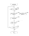
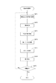
- FIG. 10 is a flowchart showing an example of the recording process in the first embodiment. This recording process is started, for example, when an operation for starting recording (such as pressing a recording button) is performed.
- an operation for starting recording such as pressing a recording button
- the imaging apparatus 100 determines whether or not the current time is within the high frame rate period (step S921). If it is within the high frame rate period (step S921: Yes), the imaging apparatus 100 performs recording at a high sampling rate of 96 kilohertz (kHz) (step S922), and extends the reproduction time of the generated high-resolution audio data. (Step S923). On the other hand, when it is not within the high frame rate period (step S921: No), the imaging apparatus 100 performs recording at a low sampling rate of 48 kilohertz (kHz) (step S924).
- kHz 48 kilohertz
- the imaging apparatus 100 encodes the audio data to generate an audio frame (step S927), and determines whether or not an operation (such as pressing a stop button) for ending the recording has been performed. (Step S928). When the operation for ending the recording is not performed (Step S928: No), the imaging apparatus 100 repeats Step S921 and the subsequent steps. On the other hand, when an operation for ending the recording is performed (step S928: Yes), the imaging apparatus 100 ends the recording process.
- the high frame rate period is set manually, but if it is set to manual, the start timing of the period may be shifted due to an operation error. Further, if the setting of the high frame rate period is set to manual, the operation of the imaging apparatus 100 becomes complicated, and the convenience of the imaging apparatus 100 may be reduced.
- the imaging apparatus 100 according to the first modification of the first embodiment is different from the first embodiment in that a high frame rate period is set without depending on a user operation.
- FIG. 11 is a block diagram illustrating a configuration example of the imaging apparatus 100 according to the first modification of the first embodiment.
- the moving image capturing unit 130 according to the first modification differs from the first embodiment in that a scene change timing is detected as a scene change timing.
- the moving image capturing unit 130 supplies the detected scene change timing to the control unit 120.
- the control unit 120 of the first modification differs from the first embodiment in that a certain period including the detected scene change timing is set as a high frame rate period. For example, a period of a certain length (such as 1 second) centered on the scene change timing is set as the high frame rate period.
- the control unit 120 is configured to set only the recording start timing and end timing according to the user's operation, but may further set a higher frame rate period according to the user's operation. For example, the control unit 120 may set a period including any one of the scene change timing and the timing designated by the user as the high frame rate period.
- FIG. 12 is a block diagram illustrating a configuration example of the moving image capturing unit 130 in the first modification of the first embodiment.
- the moving image capturing unit 130 according to the first modification is different from the first embodiment in that it further includes a buffer 132 and a scene change detection unit 133.
- the buffer 132 holds the video frame imaged by the imaging unit 131.
- the scene change detection unit 133 detects a video frame when a scene changes.
- the scene change detection unit 133 acquires a video frame from the imaging unit 131 as a current video frame, and acquires a video frame before the current video frame from the buffer 132 as a previous video frame. Then, the scene change detection unit 133 compares the current video frame and the previous video frame, and detects the presence or absence of a scene change based on the comparison result. When a scene change occurs, the scene change detection unit 133 supplies the imaging time of the frame at that time to the control unit 120 as a scene change timing.
- the imaging apparatus 100 detects the scene change timing, and sets a certain period including the timing as the high frame rate period. This eliminates the need to manually set the high frame rate period.
- the period for recording the high-resolution audio data is manually set. However, if it is set to manual, there is a possibility that an operation error may occur or the convenience of the imaging apparatus 100 may be reduced. In the first embodiment, both the recording and the recording are performed. However, as the recording time becomes longer, the data amount of the moving image data increases, and the storage capacity of the recording unit 180 may be insufficient.
- the apparatus according to the second modification of the first embodiment differs from the first embodiment in that the high frame rate period is set without depending on the user's operation and in that no recording is performed.
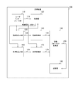
- FIG. 13 is a block diagram showing a configuration example of the recording apparatus 101 according to the second modification of the first embodiment.
- the recording apparatus 101 includes a user interface unit 110, a sensor 115, a control unit 125, an audio capturing unit 160, an audio processing unit 170, a recording format conversion unit 150, and a recording unit 180.
- the sensor 115 detects a detection target such as a suspicious person.
- a detection target such as a suspicious person.
- a piezoelectric sensor that converts a force applied to a piezoelectric body into an electrical signal or an infrared sensor that converts the amount of infrared light into an electrical signal is used as the sensor 115.
- the sensor 115 supplies a detection signal indicating whether or not a detection target is detected to the control unit 125.
- the control unit 125 causes the voice capturing unit 160 to start recording according to the operation signal, and ends recording according to the operation signal.
- the control unit 125 sets a certain period including the detection timing of the detection target as a high-resolution recording period, and the audio capturing unit 160 is relatively compared during that period. Sampling is performed at a high sampling rate.
- the audio capturing unit 160 of the second modification is the same as that of the first embodiment except that high-resolution audio data is generated in the high-resolution period instead of the high frame rate period.
- the audio processing unit 170 according to the second modification is the same as that in the first embodiment except that instead of the high frame rate period, the playback time of the high resolution audio data is converted in the high resolution period. .
- the control unit 120 is configured to set only the recording start timing and end timing according to the user's operation, but may further set a higher resolution period according to the user's operation. For example, the control unit 120 may set a period including either the detection timing of the sensor 115 or the timing specified by the user as the high resolution period.
- a moving image capturing unit 130 may be further provided, and the scene change timing may be detected as in the first modification.
- the control unit 120 may set a period including either the detection timing of the sensor 115 or the scene change timing as the high resolution period.
- the control unit 120 may set a period including any of the detection timing of the sensor 115, the scene change timing, and the timing designated by the user as the high resolution period.
- the recording apparatus 101 sets a certain period including the detection timing of the detection target as the high-resolution recording period. There is no need to manually set the recording period. In addition, since the recording apparatus 101 performs only recording without recording, the amount of data recorded in the recording unit 180 can be reduced.
- Second Embodiment> In the first embodiment, the playback time of the high-resolution audio data is extended. However, if the playback time after the extension is short with respect to the slow playback period, there is a possibility that silent time occurs and the playback quality is lowered. is there.
- the imaging apparatus 100 according to the second embodiment differs from the first embodiment in that the silent time is shortened.
- FIG. 14 is a block diagram illustrating a configuration example of the voice capturing unit 160 according to the second embodiment.
- the voice capturing unit 160 of the second embodiment is different from the first embodiment in that it further includes an additional information generation unit 162.
- the additional information generation unit 162 generates additional information indicating signal processing to be performed on the high resolution audio data. For example, signal processing including high-resolution audio data duplication processing, volume level adjustment processing, and equalizer processing for changing frequency characteristics is executed.
- the additional information generation unit 162 generates additional information including the setting contents of the signal processing.
- This setting content includes the reproduction time of the high resolution audio data, the number of times of duplication in the duplication processing of the high resolution audio data, and the like.
- n is a magnification for extending the reproduction time of high-resolution audio data. If the number of times of copying does not become an integer, fraction processing such as rounding down is performed.
- the additional information generation unit 162 adds the generated additional information to the audio data and supplies the audio data to the audio processing unit 170.
- FIG. 15 is a block diagram illustrating a configuration example of the audio processing unit 170 according to the second embodiment.
- the audio processing unit 170 according to the second embodiment is different from the first embodiment in that it further includes a duplication unit 173 and an effect processing unit 174.
- the effect processing unit 174 includes a gain adjustment unit 175 and an equalizer processing unit 176.
- the circuit including the duplicating unit 173 and the effect processing unit 174 is an example of a signal processing unit described in the claims.
- the duplicating unit 173 duplicates high-resolution audio data.
- the duplicating unit 173 performs duplication over the number of duplications indicated by the additional information, and supplies each of the generated duplicate audio data to the gain adjusting unit 175 as duplicate audio data.
- the gain adjusting unit 175 adjusts the volume level of the duplicate audio data by gain.
- the gain adjusting unit 175 adjusts the volume level with a different gain for each piece of duplicate audio data, for example, according to the additional information. For example, a gain change amount for each duplicate audio data is set in the additional information.
- the gain adjusting unit 175 supplies the duplicate audio data whose volume level has been adjusted to the equalizer processing unit 176.
- the equalizer processing unit 176 performs an equalizer process for changing the frequency characteristics of the duplicate audio data to different characteristics. For example, the equalizer processing unit 176 performs a process for making the gain for the low frequency region lower than the predetermined threshold relatively higher than the gain for the high frequency region higher than the threshold for each duplicate audio data, and the later the reproduction time is, , Lower the threshold. By changing the frequency characteristics as described above, it is possible to obtain an acoustic effect in which the degree of enhancement of the sound in the low frequency region gradually increases as time passes.
- an equalizer value is set in the additional information.
- the equalizer value includes a band for controlling the gain, a gain control amount, and the like.
- the equalizer processing unit 176 supplies the speech signal after the equalizer processing to the speech encoding unit 177.
- the equalizer processing unit 176 may gradually emphasize the high frequency region, or may change the gain for a certain band centered on a predetermined center frequency.
- the audio processing unit 170 performs all of the duplication processing, the volume level adjustment processing, and the equalizer processing, but is not limited to this configuration, and executes part of these processing (only duplication processing or the like). It may be a configuration. In addition to the duplication process, the volume level adjustment process, the equalizer process, and the like, the audio processing unit 170 may further execute a signal process (such as a noise removal process) different from these.
- a signal process such as a noise removal process
- the audio processing unit 170 executes each process in the order of change of reproduction time, duplication, volume level adjustment, and equalizer process, the respective processes may be executed in a different order.
- the audio processing unit 170 may change the reproduction time after copying, or may copy after adjusting the volume level.
- FIG. 16 is a diagram illustrating an example of a stream according to the second embodiment.
- a is a figure which shows an example of the video frame image
- B in the figure shows an example of a frame after frame rate conversion.
- C in the figure is a diagram showing an example of sampled audio data.
- d indicates an example of a video frame in which a playback time is set.
- the audio processing unit 170 extends the reproduction time of the audio data Sa2 (high-resolution audio data), duplicates the expanded Sa2, and duplicates audio data Sa2′-1 to Sa2′-m (m is an integer of 2 or more) M audio data are generated.
- the reproduction time of the first duplicate audio data Sa2′-1 is set, for example, at the start timing of the slow reproduction period. Since these duplicate audio data are the same as the original audio data, the same audio is repeatedly reproduced during the slow reproduction period. Thereby, compared with the case where it does not reproduce repeatedly, the silence time within a slow reproduction period can be shortened.
- 16 is a diagram illustrating an example of a gain used for adjusting the volume of each piece of duplicate audio data.
- the vertical axis of f indicates gain, and the horizontal axis indicates time.
- a gain of “0” decibel (dB) is set for the duplicate audio data Sa2′-1 that is reproduced first.
- dB decibel
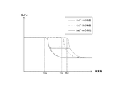
- FIG. 17 is a graph showing an example of frequency characteristics in the second embodiment.
- the vertical axis represents gain
- the horizontal axis represents frequency.
- the dotted curve indicates the characteristics of the duplicate audio data Sa2′-1 that is reproduced first in the slow reproduction period
- the dashed line curve indicates the characteristics of the duplicate audio data Sa2′-2 that is reproduced next. Show.
- the solid curve indicates the characteristics of the duplicate audio data Sa2′-m that is reproduced last in the slow reproduction period.
- the gain in the high frequency region is adjusted to be relatively low with respect to the threshold Th1
- the duplicate audio data Sa2′-2 the high frequency is obtained with respect to the threshold Th2 lower than the threshold Th1.
- the area gain is adjusted to be relatively low.
- the gain in the high frequency region is adjusted to be relatively low with respect to the threshold value Thm lower than them.
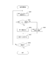
- FIG. 18 is a flowchart illustrating an example of a recording process according to the second embodiment.
- the recording process of the second embodiment is different from the first embodiment in that steps S924 and S925 are further executed.
- the imaging apparatus 100 duplicates the high-resolution audio data (step S924), and executes effect processing such as volume level adjustment and equalizer processing (step S925). After step S924 or S925, the imaging apparatus 100 encodes audio data (step S927).
- the audio processing unit 170 performs the duplication processing on the high-resolution audio data, and therefore can repeatedly reproduce the same audio.
- the audio processing unit 170 since the audio processing unit 170 performs an equalizer process that changes the frequency characteristics of the high-resolution audio data, it is possible to generate an acoustic effect such as an increase in the degree of emphasis on the audio in the low frequency region. A sense of reality can be improved by these repeated reproduction and sound effects.
- the imaging apparatus 100 performs signal processing such as audio data duplication at the time of recording. However, if duplication or the like is performed at the time of recording, the data size necessary for recording the stream increases. . From the viewpoint of reducing the data size, it is desirable to perform signal processing such as replication during reproduction.
- the imaging apparatus 100 according to the second embodiment is different from the first embodiment in that signal processing of audio data is performed during reproduction.
- FIG. 19 is a block diagram illustrating a configuration example of the imaging system according to the second embodiment.
- This imaging system includes an imaging device 100 and a playback device 200.
- the imaging apparatus 100 according to the second embodiment is different from the first embodiment in that a metadata generation unit 190 is further provided.
- the metadata generation unit 190 generates detailed setting data indicating the playback time of high-resolution audio data and the content of signal processing (such as the number of copies) from the additional information, stores it in the metadata, and converts the metadata into a recording format To the unit 150.
- the recording format conversion unit 150 adds metadata to the stream and supplies it to the playback device 200.
- the playback device 200 is a device that plays back a stream.
- FIG. 20 is a block diagram illustrating a configuration example of the playback device 200 according to the third embodiment.
- the playback device 200 includes a user interface unit 210, a metadata separation unit 220, a playback control unit 230, a decoding unit 240, a duplication unit 250, an effect processing unit 260, a display unit 270, and a speaker 280.
- the user interface unit 210 generates an operation signal in accordance with a user operation.
- the operation signal includes, for example, a signal instructing to start or stop playback of the stream.
- the user interface unit 210 supplies an operation signal to the metadata separation unit 220.
- the metadata separation unit 220 acquires a stream according to an operation signal, and separates the stream into metadata and encoded data (video packet or audio packet).
- the metadata separation unit 220 supplies the separated metadata to the reproduction control unit 230 and supplies the encoded data to the decoding unit 240.
- the decoding unit 240 decodes the encoded data into the original audio data and moving image data.
- the decoding unit 240 supplies the audio data obtained by the decoding to the duplication unit 250 and supplies the moving image data to the display unit 270.
- the display unit 270 displays moving image data.
- the reproduction control unit 230 controls the duplication unit 250 and the effect processing unit 260.
- the reproduction control unit 230 acquires the reproduction time and the number of times of duplication of high-resolution audio data and the setting contents of effect processing from the metadata, and supplies the audio reproduction time and the number of times of duplication to the duplication unit 250. Further, the playback control unit 230 supplies the effect processing setting content to the effect processing unit 260.
- the duplication unit 250 duplicates audio data according to the control of the reproduction control unit 230. Each time the audio data from the decoding unit 240 is supplied, the duplicating unit 250 determines whether or not the reproduction time matches the reproduction time from the reproduction control unit 230. If they match, the duplication unit 250 duplicates the audio data according to the number of duplications set by the reproduction control unit 230 and supplies it to the effect processing unit 260. On the other hand, when the reproduction times do not match, the duplication unit 250 supplies the audio data to the speaker 280 without duplicating.
- the effect processing unit 260 performs different signal processing on each of the duplicate audio data according to the control of the reproduction control unit 230.
- the effect processing unit 260 performs gain adjustment processing, equalizer processing, and the like, and supplies the processed duplicate audio data to the speaker 280.
- the speaker 280 reproduces sound by converting sound data into physical vibration.
- reproducing apparatus 200 is configured to be provided outside the imaging apparatus 100, the function of the reproducing apparatus 200 may be provided in the imaging apparatus 100.
- FIG. 21 is a diagram illustrating an example of a setting destination field when using MPEG4-AAC in the third embodiment.
- the metadata 510 of the MPEG4-AAC standard for example, detailed setting data is stored in a DSE (Data Stream Element) area 511.
- DSE Data Stream Element
- FIG. 22 is a diagram illustrating an example of a setting destination field when using the MPEG4-system in the second embodiment. As illustrated in the figure, in the metadata 520 of the MPEG4-system standard, for example, detailed setting data is stored in the udta area 521.
- FIG. 23 is a diagram illustrating an example of a setting destination field when the HMMP file format according to the second embodiment is used. As illustrated in the figure, in the metadata 530 of the HMMP standard, for example, detailed setting data is stored in the uuid area 531.
- FIG. 24 is a flowchart illustrating an example of a recording process according to the third embodiment.
- the recording process of the third embodiment is different from the first embodiment in that step S926 is further executed.
- step S923 or S924 the imaging apparatus 100 generates metadata that stores the setting content (step S926), and executes step S927 and subsequent steps.
- FIG. 25 is a flowchart illustrating an example of a reproduction process according to the third embodiment. This operation is started, for example, when an operation for reproducing a stream (such as pressing a reproduction button) is performed.
- the playback device 200 performs a decoding process for decoding the encoded data (step S951), and refers to the metadata to determine whether or not the decoded audio data is high-resolution audio data to be copied (step S951). S952). When it is a duplication target (step S952: Yes), the playback device 200 duplicates the high-resolution audio data (step S953), and executes effect processing such as volume adjustment and equalizer processing (step S954).
- step S952 If not to be replicated (step S952: No) or after step S954, the playback device 200 plays back the moving image and the sound with the display unit and the speaker (step S955). Then, the playback device 200 determines whether it is the playback end time (step S956). If it is not the reproduction end time (step S956: No), the imaging apparatus 100 repeats step S951 and subsequent steps. On the other hand, when it is the playback end time (step S956: Yes), the playback device 200 ends the playback process.
- the reproduction apparatus 200 performs high-resolution audio data duplication processing and the like, so that it is not necessary for the imaging apparatus 100 to duplicate audio data during recording.
- the data size required for recording can be reduced.
- the imaging apparatus 100 generates metadata indicating signal processing setting contents (such as the number of times of copying). However, the setting contents may be changed according to a user operation.
- the imaging system according to the fourth embodiment is different from the third embodiment in that setting contents such as the number of copying are changed in accordance with a user operation.
- FIG. 26 is a block diagram illustrating a configuration example of the imaging system according to the fourth embodiment.
- the imaging system according to the fourth embodiment is different from the third embodiment in that an editing apparatus 300 is provided instead of the playback apparatus 200.
- the editing apparatus 300 includes a user interface unit 310, a metadata separation unit 320, an editing control unit 330, a decoding unit 340, a reproduction time conversion unit 350, a duplication unit 360, an effect processing unit 370, and a re-encoding unit 380.
- the user interface unit 310 generates an operation signal in accordance with a user operation. For example, an operation signal instructing change of setting contents in the metadata is generated.
- the user interface unit 310 supplies the generated operation signal to the editing control unit 330.
- the metadata separation unit 320 separates the stream into metadata and encoded data according to the operation signal.
- the metadata separation unit 320 supplies the separated metadata to the editing control unit 330 and supplies the encoded data to the decoding unit 340.
- the editing control unit 330 changes the setting contents of the metadata according to the operation signal. When one of the number of times of copying and the magnification is changed by the user, the editing control unit 330 changes the other so as to satisfy Expression 3.
- the editing control unit 330 supplies the reproduction time to be copied to the decoding unit 340. Further, the edit control unit 330 supplies the changed magnification to the reproduction time conversion unit 350, supplies the number of duplications to the duplication unit 360, and supplies the effect processing setting contents to the effect processing unit 370.
- the decoding unit 340 decodes the encoded data.
- the decoding unit 340 supplies the decoded high-resolution audio data to the reproduction time conversion unit 350. Normal audio data and moving image data are supplied to the imaging apparatus 100 without being decoded.
- the reproduction time conversion unit 350 extends the reproduction time of the audio data from the decoding unit 340 according to the control of the editing control unit 330.
- the reproduction time conversion unit 350 supplies the audio data with the reproduction time extended to the duplication unit 360.
- the duplication unit 360 duplicates the high-resolution audio data according to the control of the editing control unit 330.
- the duplication unit 360 duplicates the high-resolution audio data and supplies it to the effect processing unit 370.
- the effect processing unit 370 performs signal processing such as volume level adjustment processing and equalizer processing under the control of the editing control unit 330.
- the effect processing unit 370 supplies the duplicate audio data after the signal processing to the re-encoding unit 380.
- the re-encoding unit 380 re-encodes the high resolution audio data.
- the re-encoding unit 380 supplies the stream generated by the encoding to the imaging device 100.
- the reproduction quality can be further improved by finely adjusting the reproduction time and the number of times of copying by the user. For example, if the user feels that the current playback speed is too slow for the setting of duplicating the playback time by “2” times and “5” times, the magnification is changed to “1.5” times or the like. . When the magnification is changed to “1.5” times, the editing apparatus 300 changes the number of duplications using Equation 3.
- each circuit in the editing device 300 may be provided inside the imaging device 100.
- FIG. 27 is a flowchart illustrating an example of editing processing according to the third embodiment. This editing process is started, for example, when an application for editing metadata is executed.
- the editing apparatus 300 separates the metadata, and changes the number of times of copying and the magnification in the metadata according to the user's operation (step S971).
- the editing apparatus 300 executes a decoding process for decoding the encoded data (step S972), and changes the reproduction time of the audio signal to be copied (step S973).
- the editing apparatus 300 duplicates the high resolution audio data whose reproduction time has been changed (step S974), and executes effect processing for each of the duplicate audio signals (step S975).
- the editing apparatus 300 re-encodes the duplicate audio data (step S976) and determines whether or not an operation for ending the editing has been performed (step S977). If an operation for ending editing has not been performed (step S977: No), the imaging apparatus 100 repeats step S971 and subsequent steps. On the other hand, when an operation for ending editing is performed (step S977: Yes), the imaging apparatus 100 ends the editing process.
- the editing apparatus 300 changes settings such as the number of times of reproduction and the reproduction time in the metadata according to the user's operation. Adjustments can be made to further improve playback quality.
- the audio capturing unit 160 samples the normal audio data by switching the sampling rate using the sampling rate variable microphone 161.
- the audio capturing unit 160 can also generate normal audio data by resampling high-resolution audio data sampled by a microphone having a fixed sampling rate.
- the sound capturing unit 160 according to the fifth embodiment is different from the first embodiment in that normal sound data is generated by resampling high resolution sound data.
- FIG. 28 is a block diagram illustrating a configuration example of the voice capturing unit 160 according to the fifth embodiment.
- the sound capturing unit 160 of the fifth embodiment is different from that of the first embodiment in that a high-resolution microphone 163 and a sampling rate converter 164 are provided instead of the sampling rate variable microphone 161.
- the high-resolution microphone 163 generates high-resolution audio data by sampling audio at a higher sampling rate (96 kHz, etc.) than a predetermined sampling rate (48 kHz, etc.) according to the control signal.
- the high resolution microphone 163 generates high resolution audio data over a period from the recording start timing to the recording end timing, and supplies the high resolution audio data to the sampling rate converter 164.
- the sampling rate converter 164 resamples high-resolution audio data at a predetermined sampling rate (eg, 48 kHz) outside the high frame rate period indicated by the control signal.
- the sampling rate converter 164 supplies the audio data after the sampling rate conversion to the audio processing unit 170 as normal audio data.
- high-resolution audio data within the high frame rate period is supplied to the audio processing unit 170 as it is.
- a digital microphone that outputs digital audio data is provided as the high-resolution microphone 163
- an analog microphone that outputs an analog audio signal may be provided instead of the digital microphone.
- an AD converter that AD converts an audio signal from the analog microphone is further provided between the analog microphone and the sampling rate conversion unit 164, and the AD converter performs sampling at a high sampling rate.
- the sampling rate converter 164 may gradually convert the sampling rate step by step. For example, the sampling rate converter 164 gradually increases the sampling rate at the time of resampling over a certain time from the start of the high frame rate period. In addition, the audio capturing unit 160 slightly decreases the sampling rate over a period from a point in time before the end of the high frame rate period to the end point.
- the sound capturing unit 160 may add an equalizer processing unit after the sampling rate conversion unit 164 in order to reduce a sense of incongruity at a portion where the sampling rate changes.
- the equalizer processing unit gradually adjusts the volume level of the high frequency band whose frequency is higher than a certain value by the gain step by step. For example, the equalizer processing unit gradually increases the volume level of the high frequency band over a certain time from the start of the high frame rate period. In addition, the equalizer processing unit gradually decreases the volume level in the high frequency band over a period from a time point a certain time before the end point of the high frame rate period to the end point.
- FIG. 29 is a flowchart showing an example of a recording process in the fifth embodiment.
- the recording process of the fifth embodiment is different from the first embodiment in that steps S931 and S932 are executed instead of steps S922 and S924.
- the imaging apparatus 100 records at a high sampling rate of 96 kilohertz (kHz) (step S931), and determines whether or not the current time is within the high frame rate period. (Step S912). When it is within the high frame rate period (step S921: Yes), the imaging apparatus 100 converts the reproduction time of the generated high resolution audio data (step S923). On the other hand, when it is not within the high frame rate period (step S921: No), the imaging apparatus 100 converts the sampling rate to a low sampling rate of 48 kilohertz (kHz) (step S932). After step S923 or S932, the imaging apparatus 100 encodes audio data (step S927).
- kHz 48 kilohertz
- normal audio data is generated by re-sampling high-resolution audio data outside the high frame rate period. Audio data can be generated.
- the audio capturing unit 160 samples the normal audio data by switching the sampling rate with the single sampling rate variable microphone 161.
- the audio capturing unit 160 can also generate high-resolution audio data and normal audio data using two microphones having different sampling rates.
- the sound capturing unit 160 of the sixth embodiment is different from the first embodiment in that high-resolution sound data and normal sound data are generated by two microphones having different sampling rates.
- FIG. 30 is a block diagram illustrating a configuration example of the voice capturing unit 160 according to the sixth embodiment.
- the voice capturing unit 160 of the sixth embodiment includes a high-resolution microphone 163, a normal microphone 165, a synchronization output unit 166, a sampling rate converter 164, and a synthesis unit 167.
- the normal microphone 165 generates normal sound data by sampling sound at a predetermined sampling rate (48 kHz, etc.) according to the control signal.
- the normal microphone 165 generates normal audio data over a period from the recording start timing to the recording end timing, and supplies the normal audio data to the synchronization output unit 166.
- the high-resolution microphone 163 generates high-resolution audio data by sampling audio at a sampling rate higher than a predetermined sampling rate (96 kHz, etc.) according to the control signal.
- the high-resolution microphone 163 generates high-resolution audio data over a period from the recording start timing to the recording end timing, and supplies the high-resolution audio data to the synchronization output unit 166.
- voice data is provided as the high-resolution microphone 163 and the normal microphone 165, you may provide one analog microphone which outputs an analog audio
- two AD converters that AD-convert the audio signal from the analog microphone are further provided, and these AD converters perform sampling at different sampling rates.
- the synchronization output unit 166 outputs high-resolution audio data and normal audio data in synchronization with a predetermined synchronization signal.
- the synchronization output unit 166 outputs normal audio data to the sampling rate converter 164 and outputs high resolution audio data to the synthesis unit 167.
- the sampling rate converter 164 converts the sampling rate of normal audio data to a higher sampling rate as necessary.
- the sampling rate converter 164 supplies the converted normal audio data to the synthesis unit 167.
- the synthesizing unit 167 synthesizes normal audio data and high resolution audio data.
- the synthesizer 167 sets the ratio of high resolution audio data to “0” outside the high frame rate period, and selects and outputs only normal audio data.
- the synthesis unit 167 outputs audio data obtained by synthesizing normal audio data with high resolution audio data if within the fade period, and if not within the fade period, the ratio of the high resolution audio data Is set to “1” to select and output high-resolution audio data.
- the synthesizing unit 167 is an example of a selection unit described in the claims.
- the fade period consists of a fade-in period and a fade-out period.
- the fade-in period is a period from when the high frame rate period starts until a certain time elapses.
- the fade-out period is a period from a timing a certain time before the end timing of the high frame rate period to the end timing.
- the synthesizing unit 167 increases the ratio of high-resolution audio data in synthesis every time a unit time shorter than the fade-in period elapses in the fade-in period. Thereby, the ratio of the high resolution audio data gradually increases.
- the synthesis unit 167 lowers the ratio of high-resolution audio data in synthesis every time a unit time shorter than the fade-out period elapses in the fade-out period. As a result, the proportion of high-resolution audio data is gradually reduced. In this manner, the process of gradually changing the data ratio by fading in and fading out is called a cross fade process. By this cross-fade processing, it is possible to reduce a sense of incongruity at the switching from one of the normal audio data and the high resolution audio data to the other.
- the voice capturing unit 160 may include a selector or the like instead of the synthesizing unit 167, and may switch and output the voice data without performing the cross-fade process.
- an equalizer processing unit may be added after the selector, and the equalizer processing unit may gradually adjust the volume level of the high frequency band stepwise with a gain. For example, the equalizer processing unit may gradually increase the volume level in the high frequency band during the period corresponding to the fade-in period, and gradually decrease the volume level in the high frequency band during the period corresponding to the fade-out period. .
- the voice capturing unit 160 samples the voice with two microphones, but may sample with three or more microphones.
- three microphones having sampling rates of 48, 96, and 192 kilohertz (kHz) may be provided, and the combining unit 167 may combine them.
- the synthesis unit 167 synthesizes a 48 kilohertz voice and a 96 kilohertz voice from the start time point within the fade-in period to a certain time point, and gradually increases the 96 kilohertz rate. Then, from that time to the end of the fade-in period, the synthesizer 167 synthesizes the 96 kHz sound and the 192 kHz sound, and gradually increases the ratio of 192 kHz. In the fade-out period, the synthesis unit 167 may perform processing in contrast with the fade-in period.
- FIG. 31 is a graph showing an example of a change in the composition ratio in the sixth embodiment.
- the vertical axis indicates the synthesis ratio of high-resolution audio data
- the horizontal axis indicates time.
- the composition ratio of the high resolution frame rate is set to “0” outside the high frame rate period. Based on this synthesis ratio, the synthesis unit 167 selects and outputs normal audio data.
- the synthesis unit 167 performs synthesis by gradually increasing the ratio of the high-resolution audio data.
- the synthesis unit 167 performs synthesis by gradually reducing the ratio of the high-resolution audio data. Further, the ratio of the high-resolution audio data is set to “1” outside the fade period in the high frame rate period. Based on this synthesis ratio, the synthesis unit 167 selects and outputs high-resolution audio data.
- FIG. 32 is a flowchart showing an example of a recording process in the sixth embodiment.
- the imaging apparatus 100 first records at a high sampling rate (such as 96 kilohertz) and a low sampling rate (such as 48 kilohertz) (step S941). Then, the imaging apparatus 100 determines whether or not the current time is within the high frame rate period (step S942).
- a high sampling rate such as 96 kilohertz
- a low sampling rate such as 48 kilohertz
- step S942 When it is within the high frame rate period (step S942: Yes), the imaging apparatus 100 converts the sampling rate of the normal audio data as necessary (step S943). Then, the imaging apparatus 100 performs a cross fade process (step S944). On the other hand, when it is outside the high frame rate period (step S942: No), the imaging apparatus 100 selects normal audio data (step S945).
- step S944 or S945 the imaging apparatus 100 encodes the audio data (step S946), and determines whether or not an operation (such as pressing a stop button) for ending the recording has been performed (step S947).
- step S947: No the imaging apparatus 100 repeats step S941 and the subsequent steps.
- step S947: Yes the imaging apparatus 100 ends the recording process.
- the imaging apparatus 100 since the imaging apparatus 100 separately generates high-resolution audio data and normal audio data, and selects and outputs either of them, the audio data Can be generated without using the sampling rate variable microphone 161.
- the processing procedure described in the above embodiment may be regarded as a method having a series of these procedures, and a program for causing a computer to execute these series of procedures or a recording medium storing the program. You may catch it.
- a recording medium for example, a CD (Compact Disc), an MD (MiniDisc), a DVD (Digital Versatile Disc), a memory card, a Blu-ray disc (Blu-ray (registered trademark) Disc), or the like can be used.
- this technique can also take the following structures.
- a process of sampling audio within a predetermined period at a sampling rate higher than a predetermined sampling rate to generate audio data as high-resolution audio data, and sampling audio outside the predetermined period at the predetermined sampling rate A sampling processing unit that performs processing for generating audio data as normal audio data;
- a recording apparatus comprising: a reproduction time conversion unit that extends the reproduction time of the high-resolution audio data.
- the sampling processing unit samples the sound at the predetermined sampling rate outside the predetermined period, and switches the sampling rate to a sampling rate higher than the predetermined sampling rate within the predetermined period.
- sampling processing unit A high-resolution microphone that samples the audio at a sampling rate higher than the predetermined sampling rate to generate the high-resolution audio data;
- the recording apparatus according to (1) further comprising a sampling rate converter that resamples the high-resolution audio data at the predetermined sampling rate outside the predetermined period to generate the normal audio data.
- the sampling processing unit A high-resolution microphone that generates the high-resolution audio data by sampling the audio at a sampling rate higher than the predetermined sampling rate; and a normal microphone that generates the normal audio data by sampling the audio at the predetermined sampling rate;
- the recording apparatus further comprising: a selection unit that selects and outputs the high-resolution audio data within the predetermined period, and selects and outputs the normal audio data outside the predetermined period.
- the selection unit performs a synthesis process of synthesizing the normal audio data with the high-resolution audio data in a certain fade period within the predetermined period.
- the recording apparatus (13) The recording apparatus according to (11) or (12), wherein the signal processing unit adjusts a volume level of the high-resolution audio data by a predetermined gain. (14) The recording apparatus according to any one of (11) to (13), wherein the signal processing unit changes a frequency characteristic of the high-resolution audio data. (15) A process of sampling audio within a predetermined period at a sampling rate higher than a predetermined sampling rate to generate audio data as high resolution audio data, and sampling audio outside the predetermined period at the predetermined sampling rate Setting information indicating signal processing to be performed on the high-resolution audio data obtained by extending the reproduction time of the high-resolution audio data and extending the reproduction time.
- a recording device for generating metadata including: A recording system comprising: a playback device that executes the signal processing according to the setting information and reproduces the high-resolution audio data and the normal audio data that have been subjected to the signal processing.
- the metadata format is MPEG4-AAC.
- the format of the metadata is MPEG4-system, The recording system according to (15), wherein the recording device records the setting information in an udta area of the metadata.
- the format of the metadata is HMMP (Home and Mobile Multimedia Platform),
- (19) A process of sampling audio within a predetermined period at a sampling rate higher than a predetermined sampling rate to generate audio data as high-resolution audio data, and sampling audio outside the predetermined period at the predetermined sampling rate Setting information indicating signal processing to be performed on the high-resolution audio data obtained by extending the reproduction time of the high-resolution audio data and extending the reproduction time.
- a recording device for generating metadata including:
- Sampling processing procedure for performing processing for generating audio data as normal audio data A recording method comprising: a playback time conversion procedure for extending the playback time of the high-resolution audio data.
- Imaging device 101 Recording apparatus 110, 210, 310 User interface part 115 Sensor 120, 125 Control part 130 Movie capturing part 131 Imaging part 132,171 Buffer 133 Scene change detection part 134 Frame rate conversion part 140 Movie processing part 150
- Recording format conversion Unit 160 audio capturing unit 161 sampling rate variable microphone 162 additional information generation unit 163 high resolution microphone 164 sampling rate converter 165 normal microphone 166 synchronization output unit 167 synthesis unit 170 audio processing unit 172, 350 reproduction time conversion unit 173, 250, 360 Replication unit 174, 260, 370 Effect processing unit 175 Gain adjustment unit 176
- Equalizer processing unit 177 Audio encoding unit 180 Recording unit 190 Metadata generation unit 200 Raw device 220 and 320 the metadata separation unit 230 the reproduction control unit 240, 340 decoding unit 270 display unit 280 speaker 300 editing device 330 edits the control unit 380 re-encoding unit
Landscapes
- Engineering & Computer Science (AREA)
- Multimedia (AREA)
- Signal Processing (AREA)
- Physics & Mathematics (AREA)
- Computer Security & Cryptography (AREA)
- Audiology, Speech & Language Pathology (AREA)
- Computational Linguistics (AREA)
- Health & Medical Sciences (AREA)
- Human Computer Interaction (AREA)
- Acoustics & Sound (AREA)
- Quality & Reliability (AREA)
- Spectroscopy & Molecular Physics (AREA)
- Theoretical Computer Science (AREA)
- Television Signal Processing For Recording (AREA)
- Signal Processing For Digital Recording And Reproducing (AREA)
- Studio Devices (AREA)
Abstract
音声を録音して再生時間を伸長する装置において音質の低下を抑制する。 サンプリング処理部は、所定のサンプリングレートより高いサンプリングレートで所定の期間内において音声をサンプリングして音声データを高解像度音声データとして生成する処理と前記所定のサンプリングレートで前記所定の期間外において音声をサンプリングして音声データを通常音声データとして生成する処理とを行う。また、再生時間変換部は、高解像度音声データの再生時間を伸長する。
Description
本技術は、録音装置、録音システム、および、録音方法に関する。詳しくは、音声データの再生時間を変更する録音装置、録音システム、および、録音方法に関する。
従来より、音声を聞き取りやすくする目的で、音声の再生時間を引き伸ばす処理が行われている。例えば、動画をスロー再生させる際に、その動画に同期して録音された音声の再生時間を伸長する撮像装置が提案されている(例えば、特許文献1参照。)。
しかしながら、上述の撮像装置では、音声の再生時間を長くするほど音質が低下してしまう。例えば、再生時間を2倍にすると、再生時間を伸長しない場合と比較して音声の周波数は1/2に低下し、音程が約1オクターブ低下する。このように再生時間を伸長した部分と伸長していない部分とのそれぞれの音質の差異が大きくなって違和感が生じ、音声全体の再生品質が低下するという問題がある。
本技術はこのような状況に鑑みて生み出されたものであり、音声を録音して再生時間を伸長する装置において音質の低下を抑制することを目的とする。
本技術は、上述の問題点を解消するためになされたものであり、その第1の側面は、所定のサンプリングレートより高いサンプリングレートで所定の期間内において音声をサンプリングして音声データを高解像度音声データとして生成する処理と上記所定のサンプリングレートで上記所定の期間外において音声をサンプリングして音声データを通常音声データとして生成する処理とを行うサンプリング処理部と、上記高解像度音声データの再生時間を伸長する再生時間変換部とを具備する録音装置、および、録音方法である。これにより、所定のサンプリングレートより高いサンプリングレートで所定の期間内においてサンプリングされた高解像度音声データの再生時間が伸長されるという作用をもたらす。
また、この第1の側面において、上記サンプリング処理部は、上記所定の期間外において上記所定のサンプリングレートで上記音声をサンプリングし、上記所定の期間内において上記所定のサンプリングレートより高いサンプリングレートにサンプリングレートを切り替えて上記音声をサンプリングしてもよい。これにより、上記所定の期間内においてサンプリングレートが切り替えられるという作用をもたらす。
また、この第1の側面において、上記サンプリング処理部は、上記所定のサンプリングレートより高いサンプリングレートで上記音声をサンプリングして上記高解像度音声データを生成する高解像度マイクと、上記所定の期間外において上記高解像度音声データを上記所定のサンプリングレートでリサンプリングして上記通常音声データを生成するサンプリングレート変換器とを備えてもよい。これにより、高解像度音声データのリサンプリングにより通常音声データが生成されるという作用をもたらす。
また、この第1の側面において、上記サンプリング処理部は、上記所定のサンプリングレートより高いサンプリングレートで上記音声をサンプリングして上記高解像度音声データを生成する高解像度マイクと上記所定のサンプリングレートで上記音声をサンプリングして上記通常音声データを生成する通常マイクと、上記所定の期間内において上記高解像度音声データを選択して出力し、上記所定の期間外において上記通常音声データを選択して出力する選択部とを備えてもよい。これにより、所定の期間内において高解像度音声データが選択され、所定の期間外において通常音声データが選択されるという作用をもたらす。
また、この第1の側面において、上記選択部は、上記所定の期間内の一定のフェード期間において上記高解像度音声データに上記通常音声データを合成する合成処理を行ってもよい。これにより、一定のフェード期間において高解像音声データに通常音声データが合成されるという作用をもたらす。
また、この第1の側面において、上記選択部は、上記合成処理において上記フェード期間より短い単位時間が経過するたびに上記高解像度音声データの割合を変更してもよい。これにより、単位時間が経過するたびに高解像度音声データの割合が変更されるという作用をもたらす。
また、この第1の側面において、所定のフレームレートより高いフレームレートで複数のフレームを撮像する撮像部と、上記複数のフレームのうち上記所定の期間外に撮像されたフレームのフレームレートを上記所定のフレームレートに変換するフレームレート変換部とをさらに具備してもよい。これにより、所定のフレームレートより高いフレームレートで所定の期間外に撮像された複数のフレームのフレームレートが所定のフレームレートに変換されるという作用をもたらす。
また、この第1の側面において、所定のタイミングを含む期間を上記所定の期間として設定する制御部をさらに具備してもよい。これにより、所定のタイミングを含む期間が所定の期間として設定されるという作用をもたらす。
また、この第1の側面において、上記複数のフレームの中からシーンが変化したシーン変化タイミングを検出するシーン変化検出部をさらに具備し、上記制御部は、上記シーン変化タイミングを含む期間を上記所定の期間として設定してもよい。これにより、シーン変化タイミングを含む期間が所定の期間として設定されるという作用をもたらす。
また、この第1の側面において、所定の検知対象を検知するセンサーをさらに具備し、上記制御部は、上記検知対象が検知されたタイミングを含む期間を上記所定の期間に設定してもよい。これにより、検知対象が検知されたタイミングを含む期間が所定の期間として設定されるという作用をもたらす。
また、この第1の側面において、上記再生時間が伸長された高解像度音声データに対して所定の信号処理を実行する信号処理部をさらに具備してもよい。これにより、高解像度音声データに対して所定の信号処理が実行されるという作用をもたらす。
また、この第1の側面において、上記信号処理部は、上記高解像度音声データを複製してもよい。これにより、高解像度音声データが複製されるという作用をもたらす。
また、この第1の側面において、上記信号処理部は、上記高解像度音声データの音量レベルを所定のゲインにより調整してもよい。これにより、高解像度音声データの音量レベルが所定のゲインにより調整されるという作用をもたらす。
また、この第1の側面において、上記信号処理部は、上記高解像度音声データの周波数特性を変更してもよい。これにより、高解像度音声データの周波数特性が変更されるという作用をもたらす。
また、本技術の第2の側面は、所定のサンプリングレートより高いサンプリングレートで所定の期間内において音声をサンプリングして音声データを高解像度音声データとして生成する処理と上記所定のサンプリングレートで上記所定の期間外において音声をサンプリングして音声データを通常音声データとして生成する処理とを行い、上記高解像度音声データの再生時間を伸長し、上記再生時間を伸長した上記高解像度音声データに対して実行すべき信号処理を示す設定情報を含むメタデータを生成する録音装置と、上記設定情報に従って上記信号処理を実行して上記信号処理を実行した上記高解像度音声データと上記通常音声データとを再生する再生装置とを具備する録音システムである。これにより、所定の期間内において高解像度音声データが選択され、所定の期間外において通常音声データが選択されるという作用をもたらす。
また、この第1の側面において、上記メタデータのフォーマットは、MPEG4-AACであり、上記録音装置は、上記メタデータのDSE(Data Stream Element)領域に上記設定情報を記録してもよい。これにより、DSE領域に設定情報が記録されるという作用をもたらす。
また、この第2の側面において、上記メタデータのフォーマットは、MPEG4-systemであり、上記録音装置は、上記メタデータのudta領域に上記設定情報を記録してもよい。これにより、udta領域に上記設定情報が記録されるという作用をもたらす。
また、この第2の側面において、上記メタデータのフォーマットは、HMMP(Home and Mobile Multimedia Platform)であり、上記録音装置は、上記メタデータのuuid領域に上記設定情報を記録してもよい。これにより、uuid領域に上記設定情報が記録されるという作用をもたらす。
また、本技術の第2の側面は、所定のサンプリングレートより高いサンプリングレートで所定の期間内において音声をサンプリングして音声データを高解像度音声データとして生成する処理と上記所定のサンプリングレートで上記所定の期間外において音声をサンプリングして音声データを通常音声データとして生成する処理とを行い、上記高解像度音声データの再生時間を伸長し、上記再生時間を伸長した上記高解像度音声データに対して実行すべき信号処理を示す設定情報を含むメタデータを生成する録音装置と、上記設定情報を変更して当該変更した設定情報の示す上記信号処理を実行する編集装置とを具備する録音システムである。これにより、所定の期間内において高解像度音声データが選択され、所定の期間外において通常音声データが選択されるという作用をもたらす。
本技術によれば、音声を録音して再生時間を伸長する装置において音質の低下を抑制することができるという優れた効果を奏し得る。なお、ここに記載された効果は必ずしも限定されるものではなく、本開示中に記載されたいずれかの効果であってもよい。
以下、本技術を実施するための形態(以下、実施の形態と称する)について説明する。説明は以下の順序により行う。
1.第1の実施の形態(高解像度音声データの再生時間を伸長する例)
2.第2の実施の形態(高解像度音声データの再生時間を伸長して信号処理を行う例)
3.第3の実施の形態(高解像度音声データの再生時間を伸長してメタデータを生成する例)
4.第4の実施の形態(高解像度音声データの再生時間を伸長してメタデータを編集する例)
5.第5の実施の形態(高解像度音声データの再生時間を伸長するとともに高解像度音声データのサンプリングレートを変換する例)
6.第6の実施の形態(高解像度音声データに通常音声データを合成し、再生時間を伸長する例)
1.第1の実施の形態(高解像度音声データの再生時間を伸長する例)
2.第2の実施の形態(高解像度音声データの再生時間を伸長して信号処理を行う例)
3.第3の実施の形態(高解像度音声データの再生時間を伸長してメタデータを生成する例)
4.第4の実施の形態(高解像度音声データの再生時間を伸長してメタデータを編集する例)
5.第5の実施の形態(高解像度音声データの再生時間を伸長するとともに高解像度音声データのサンプリングレートを変換する例)
6.第6の実施の形態(高解像度音声データに通常音声データを合成し、再生時間を伸長する例)
<1.第1の実施の形態>
[撮像装置の構成例]
図1は、第1の実施の形態における撮像装置100の一構成例を示すブロック図である。この撮像装置100は、録画および録音を行う装置であり、ユーザインターフェース部110、制御部120、動画取込み部130、動画処理部140、記録フォーマット変換部150、音声取込み部160および音声処理部170および記録部180を備える。なお、撮像装置100は、特許請求の範囲に記載の録音装置の一例である。
[撮像装置の構成例]
図1は、第1の実施の形態における撮像装置100の一構成例を示すブロック図である。この撮像装置100は、録画および録音を行う装置であり、ユーザインターフェース部110、制御部120、動画取込み部130、動画処理部140、記録フォーマット変換部150、音声取込み部160および音声処理部170および記録部180を備える。なお、撮像装置100は、特許請求の範囲に記載の録音装置の一例である。
ユーザインターフェース部110は、ユーザの操作に従って操作信号を生成するものである。ユーザインターフェース部110は、生成した操作信号を制御部120に供給する。
制御部120は、操作信号に従って撮像装置100全体を制御するものである。この制御部120は、操作信号に従って録音および録画の動作を制御する制御信号を生成する。この制御信号は、例えば、録画および録音の開始タイミングと、それらの終了タイミングとを指示する信号を含む。この録画の開始タイミングは、録音の開始タイミングと同一のタイミングであるものとする。同様に、録画および録音の終了タイミングも同一のタイミングであるものとする。また、制御信号は、高フレームレート期間の開始タイミングおよび終了タイミングを指示する信号をさらに含む。
ここで、高フレームレート期間は、再生時より高いフレームレートで撮像する期間である。例えば、ユーザが所定のボタンを押したタイミングを中心とする一定の長さ(1秒など)の期間が高フレームレート期間として設定される。高フレームレート期間外のフレームレートは、再生時と同一である。高フレーム期間外(再生時)のフレームレートは例えば、60ヘルツ(Hz)に設定され、高フレームレート期間内のフレームレートは例えば、600ヘルツ(Hz)に設定される。
なお、再生時のフレームレートは、60ヘルツ(Hz)に限定されず、30ヘルツ(Hz)などであってもよい。また、高フレームレート期間内のフレームレートは、再生時よりも高い値であれば、600ヘルツ(Hz)に限定されず、120ヘルツ(Hz)などであってもよい。
制御部120は、上述の各タイミングを示す制御信号を動画取込み部130、音声取込み部160および音声処理部170に信号線129を介して供給する。
動画取込み部130は、制御信号に従って、複数のビデオフレームを順に撮像するものである。この動画取込み部130は、撮像したビデオフレームを時系列順に含む動画データを信号線139を介して動画処理部140に供給する。
動画処理部140は、動画データを符号化する処理を行うものである。この動画データは、例えば、MPEG(Moving Picture Experts Group)-2規格に従って符号化される。この動画処理部140は、符号化した動画データをビデオパケットにパケット化して記録フォーマット変換部150に信号線149を介して供給する。なお、動画処理部140は、MPEG-4など、MPEG-2以外の規格に従って符号化してもよい。
音声取込み部160は、制御信号に従って音声をサンプリングして音声データを生成するものである。この音声取込み部160は、所定のサンプリングレートで音声をサンプリングし、サンプリングのたびに音声の音量レベルをデジタルの音声データに量子化する。このように、サンプリングおよび量子化によりアナログ信号をAD(Analog to Digital)変換する方式は、PCM(Pulse Code Modulation)方式と呼ばれる。
ただし、音声取込み部160は、高フレームレート期間内において高フレーム期間外よりも高いサンプリングレートで音声をサンプリングする。高フレームレート期間内のサンプリングレートは例えば、96キロヘルツ(kHz)に設定され、高フレームレート期間外のサンプリングレートは例えば、48キロヘルツ(kHz)に設定される。以下、高フレームレート期間内にサンプリングされた音声データを「高解像度音声データ」と称し、高フレームレート期間外にサンプリングされた音声データを「通常音声データ」と称する。音声取込み部160は、これらの音声データを音声処理部170に信号線169を介して供給する。
なお、音声取込み部160は、特許請求の範囲に記載のサンプリング処理部の一例である。また、高フレームレート期間外のサンプリングレートは、高フレームレート期間内より低い値であれば、48キロヘルツ(kHz)に限定されず、44.1キロヘルツ(kHz)などであってもよい。また、高フレームレート期間内のサンプリングレートは、高フレームレート期間外より高い値であれば、96キロヘルツ(kHz)に限定されず、192キロヘルツ(kHz)などであってもよい。
音声処理部170は、制御信号に従って高解像度音声データの再生時間を一定の倍率(例えば、2倍)で伸長するものである。この音声処理部170は、再生時間を伸長した高解像度音声データと、通常音声データとを所定の符号化単位で符号化する。これらの音声データは、例えば、MPEGの規格に従って20ミリ秒(ms)の単位で符号化される。符号化単位で符号化されたそれぞれの音声信号は、「オーディオフレーム」と呼ばれる。音声処理部170は、オーディオフレームをオーディオパケットにパケット化して記録フォーマット変換部150に信号線179を介して供給する。
記録フォーマット変換部150は、ビデオパケットおよびオーディオパケットの記録フォーマットを所定のフォーマットに変換するものである。また、記録フォーマット変換部150は、オーディオフレームおよびビデオフレームのそれぞれに再生時刻を設定する。これらの再生時刻として、例えば、MPEG規格におけるPTS(Presentation Time Stamp)が設定される。ビデオフレームのPTSは、高フレームレート期間外におけるビデオフレームの撮像間隔と同一の間隔(例えば、1/60秒)で設定される。また、高解像度音声データから生成された最初のオーディオフレームのPTSは、高フレームレート期間を引き伸ばしたスロー再生期間内の所定のタイミング(開始時点や中間時点など)に設定される。そして、記録フォーマット変換部150は、フォーマット変換後のパケットからなるデータをストリームとして記録部180に信号線159を介して供給する記録部180は、ストリームを記録するものである。
なお、動画取込み部130、動画処理部140、音声取込み部160および音声処理部170などの回路を1つの装置に設けているが、これらを複数の装置に分散して設けてもよい。例えば、録画を行うための回路(動画取込み部130および動画処理部140など)のみを撮像装置100に設け、録音を行うための回路(音声取込み部160および音声処理部170など)を録音装置に設けてもよい。
[動画取込み部の構成例]
図2は、第1の実施の形態における動画取込み部130の一構成例を示すブロック図である。この動画取込み部130は、撮像部131およびフレームレート変換部134を備える。
図2は、第1の実施の形態における動画取込み部130の一構成例を示すブロック図である。この動画取込み部130は、撮像部131およびフレームレート変換部134を備える。
撮像部131は、操作信号に従って所定の垂直同期信号SYNC_VHに同期して複数のビデオフレームを時系列順に撮像するものである。この撮像部131は、例えば、撮像レンズなどの光学系と撮像素子とを備える。この撮像素子として、例えば、CMOS(Complementary Metal Oxide Semiconductor)センサーやCCD(Charge Coupled Device)センサーが用いられる。また、垂直同期信号SYNC_VHの周波数は、再生時のフレームレートより高い値であり、例えば、600ヘルツ(Hz)である。撮像部131は、制御信号の示す録画の開始タイミングから終了タイミングまでの期間に亘って撮像を行い、ビデオフレームのそれぞれをフレームレート変換部134に供給する。
フレームレート変換部134は、制御信号に従って、フレームレートを変換するものである。このフレームレート変換部134は、制御信号の示す高フレームレート期間において撮像されたビデオフレームのフレームレートを、垂直同期信号SYNC_VLの周波数(例えば、60ヘルツ:Hz)のフレームレートに変換する。例えば、ビデオフレームを一定数ごとに間引く処理により、フレームレートが変換される。一方、高フレームレート期間外において撮像されたビデオフレームのフレームレートは変換されない。フレームレート変換部134は、これらのビデオフレームを含む動画データを動画処理部140に供給する。
[音声取込み部の構成例]
図3は、第1の実施の形態における音声取込み部160の一構成例を示すブロック図である。この音声取込み部160は、サンプリングレート可変マイク161を備える。
図3は、第1の実施の形態における音声取込み部160の一構成例を示すブロック図である。この音声取込み部160は、サンプリングレート可変マイク161を備える。
サンプリングレート可変マイク161は、制御信号に従ってサンプリングレートを変更して音声をサンプリングするものである。このサンプリングレート可変マイク161は、制御信号の示す高フレームレート期間外において、一定のサンプリングレート(例えば、48キロヘルツ)で音声をサンプリングする。一方、高フレームレート期間内においてサンプリングレート可変マイク161は、サンプリングレートを高フレームレート期間外より高い値(例えば、96キロヘルツ)に切り替えて音声をサンプリングする。サンプリングレート可変マイク161は、高フレームレート期間外でサンプリングした通常音声データと、高フレームレート期間内でサンプリングした高解像度音声データとを音声処理部170に供給する。
なお、サンプリングレート可変マイク161として、デジタルの音声データを出力するデジタルマイクをもうけているが、このデジタルマイクの代わりにアナログの音声信号を出力するアナログマイクを設けてもよい。この場合には、アナログマイクからの音声信号をAD変換するAD変換器がさらに設けられ、このAD変換器がサンプリングレートを切り替えてサンプリングを行う。
また、音声取込み部160は、サンプリング周波数(サンプリングレート)を切り替える際に段階的に徐々に切り替えてもよい。例えば、高フレームレート期間の開始時点から一定時間に亘って、音声取込み部160は、サンプリングレートを少しずつ増加させる。また、高フレームレート期間の終了時点より一定時間前の時点から、その終了時点までの期間に亘って、音声取込み部160は、サンプリングレートをすこしずつ減少させる。これにより、サンプリングレートが切り替わる部分の違和感を軽減することができる。
[音声処理部の構成例]
図4は、第1の実施の形態における音声処理部170の一構成例を示すブロック図である。この音声処理部170は、バッファ171、再生時間変換部172および音声符号化部177を備える。
図4は、第1の実施の形態における音声処理部170の一構成例を示すブロック図である。この音声処理部170は、バッファ171、再生時間変換部172および音声符号化部177を備える。
バッファ171は、一定のデータ量の音声データを保持するものである。再生時間変換部172は、高解像度音声データの再生時間を変換するものである。この再生時間変換部172は、制御信号の示す高フレームレート期間内にサンプリングされた音声データ(すなわち、高解像度音声データ)をバッファ171から読み出し、その再生時間を一定の倍率で伸長して音声符号化部177に供給する。一方、高フレームレート期間外にサンプリングされた音声データは、再生時間が変更されずにそのまま音声符号化部177に供給される。
音声符号化部177は、音声データをオーディオフレームに符号化するものである。この音声符号化部177は、オーディオフレームをオーディオパケットにパケット化して記録フォーマット変換部150に信号線179を介して供給する。
図5は、第1の実施の形態におけるストリームの一例を示す図である。同図におけるaは、垂直同期信号SYNC_VHに同期して撮像されたビデオフレームの一例を示す図である。垂直同期信号SYNC_VHの周波数が600ヘルツ(Hz)である場合、1/600秒ごとに複数のビデオフレームが撮像される。
図5におけるbは、フレームレート変換後のフレームの一例を示す図である。ユーザの操作に従って高フレームレート期間が設定され、その高フレームレート期間外において、フレームレートが例えば、60ヘルツ(Hz)の低フレームレートに変換される。同図におけるcの太線で囲ったビデオフレームは、高フレームレート期間内のビデオフレームを示す。
図5におけるcは、サンプリングされた音声データの一例を示す図である。例えば、サンプリングにより音声データSa1、Sa2およびSa3が順に生成される。ここで、音声データSa1は、高フレームレート期間の開始タイミングTsより前に、比較的低いサンプリングレート(例えば、48キロヘルツ)でサンプリングされた通常音声データである。また、音声データSa2は、高フレームレート期間に亘って比較的高いサンプリングレート(例えば、96キロヘルツ)でサンプリングされた高解像度音声データである。また、音声データSa3は、高フレームレート期間の終了タイミングTeの後に、比較的低いサンプリングレートでサンプリングされた通常音声データである。
図5におけるdは、再生時刻が設定されたビデオフレームの一例を示すものである。検出フレームを含むビデオフレームのそれぞれに、例えば、60ヘルツ(Hz)の低フレームレートで再生するための再生時刻が設定される。この再生時刻に従って、高フレームレート期間に撮像された動体は、非常にゆっくりとした動きで再生される。例えば、高フレームレート期間のフレームレートが600ヘルツ(Hz)で、再生時のフレームレートが60ヘルツ(Hz)である場合、スロー再生期間は、高フレームレート期間の10倍に引き伸ばされ、動体の動作速度は1/10に低下する。
図5におけるeは、再生時間変換後の音声データの一例を示す図である。音声処理部170は、高解像度音声データ(Sa2)の再生時間を伸長して音声データSa2'を生成する。この音声データSa2'の再生時刻は、例えば、スロー再生期間の中間時点Tc'に設定される。なお、変換後の音声データSa2'の再生時刻は、スロー再生期間の中間時点Tc'に限定されず、例えば、スロー再生期間の開始タイミングTsであってもよい。また、スロー再生期間の開始タイミングTsの直前に、連続した無音の期間がある場合には、撮像装置100は、その期間の開始タイミングを音声データSa2'の再生時刻としてもよい。
図6は、第1の実施の形態における再生時間の変換前後の高解像度音声データの一例を示す図である。同図におけるaは、再生時間を変換する前の高解像度音声データの一例を示す図であり、同図におけるbは、再生時間を変換した後の高解像度音声データの一例を示す図である。また、同図において縦軸は、音量レベルを示し、横軸は時間を示す。また、点線は、音声データをDA(Digital to Analog)変換した際に復元されるアナログの音声信号の波形を示す。
図6におけるaに例示するように、高フレームレート期間において、比較的高いサンプリングレートで音声データ502および504などの音声データがサンプリングされる。例えば、サンプリングレートが96キロヘルツ(kHz)の際には、1秒当たり96×1000個の音声データが生成される。量子化ビット数を24ビットとすると、モノラルの音声データの1秒当たりのデータ量は、96×1000×24ビットである。なお、量子化ビット数は24ビットに限定されず、16ビットなどであってもよい。
そして、図6におけるbに例示するように、変換前の音声データ(502や504)の間に、音声データ503などのデータが補間される。同図において斜線を引いた部分は、補間された音声データを示す。音声処理部170は、例えば、隣り合う音声データ502および504のそれぞれの音量レベルの中間の音量レベルを示すデータを音声データ503として補間する。この補間により、音声データの再生時間が引き伸ばされる。例えば、補間により音声データの個数を2倍にした場合には、再生時間は2倍に伸長される。このように、再生時間を伸長する処理は、タイムストレッチや話速変換と呼ばれる。
ここで、サンプリングされた音声データにより復元することができるアナログの音声の最大周波数は、標本化定理より、サンプリング周波数fsの半分の値である。このサンプリング周波数の半分の値(fs/2)は、ナイキスト周波数と呼ばれる。このナイキスト周波数(復元可能な周波数)は、再生時間の伸長により低下する。例えば、再生時間を2倍にした場合には、ナイキスト周波数は半分に低下してしまう。
なお、音声処理部170は、波形をそのまま引き伸ばす処理によりタイムストレッチを行っているが、再生時間を伸長することができるのであれば、この方式に限定されない。例えば、音声処理部170は、音声波形を複数に分割し、それらの一部を複製して挿入する処理により、再生時間を引き伸ばしてもよい。この処理によれば、周波数をほとんど変えずに再生時間を伸長することができる。この場合であっても、再生時間を変換した部分で若干の音質低下が生じるため、高解像度音声データを録音することにより、その音質低下を抑制することができる。
図7は、第1の実施の形態における音声データの復元帯域の一例を示す図である。ここで、高解像度音声データのサンプリングレートは96キロヘルツ(kHz)とし、通常音声データのサンプリングレートは48キロヘルツ(kHz)とする。同図に例示するように、高解像度音声データのDA変換により復元される音声の周波数帯域(以下、「復元帯域」と称する。)は、再生時間を変換する前においては、標本化定理より0乃至48キロヘルツ(kHz)である。この高解像度音声データの再生時間を2倍に伸長すると、復元帯域は伸長前の半分、すなわち0乃至24キロヘルツ(kHz)となる。一方、通常音声データの復元帯域は、標本化定理より0乃至24キロヘルツ(kHz)となる。
ここで、一般的な人間の可聴範囲は、20ヘルツ(Hz)乃至20キロヘルツ(kHz)であり、再生時間変更後の復元帯域より狭い。したがって、再生時間を変更しても、ユーザが音質の低下を感じることがなくなる。また、再生時間変更後の高解像度音声データの復元帯域は、通常音声データと同一であるから、再生時間を引き伸ばしたスロー再生期間の音質は、引き伸ばしていない期間と変わらなくなる。
これに対して、特許文献1に記載の装置は、高フレームレート期間においても、サンプリングレートを変えずに録音している。この構成では、高フレームレート期間にサンプリングした通音声データの再生時間を引き伸ばすと、引き伸ばしていない期間と比較して復元帯域が狭くなり、音質が低下してしまう。
なお、上述の標本化定理に基づいて、通常音声データのサンプリングレートは、可聴範囲の最大周波数(約20キロヘルツ)の2倍より高い値が望ましい。また、高解像度音声データのサンプリングレートは、可聴範囲の最大周波数の2倍に、再生時間に対する倍率(2倍など)を乗じた値より高い値が望ましい。
図8は、第1の実施の形態におけるストリームおよびパケットのデータ構造の一例を示す図である。同図におけるaは、ストリームのデータ構造の一例を示す図である。MPEG-2TS規格においてストリームは、例えば、補助的なデータを含むパケットARI_PCKと、ビデオパケットV_PCKと、オーディオパケットA_PCKとを含む。ビデオフレームは、1つ以上のビデオパケットV_PCKに格納され、オーディオフレームは、1つ以上のオーディオパケットA_PCKに格納される。
図8におけるbは、ビデオパケットV_PCKのデータ構造の一例を示す図である。MPEG-2TS規格においてビデオパケットV_PCKには、パケット開始コードと、パケット長と、「10」のコードと、フラグおよび制御と、PESヘッダ長と、コンディショナル・コーディングと、パケット・データとが格納される。なお、オーディオパケットのデータ構造は、ビデオパケットと同様である。
パケット開始コードのフィールドには、パケットの先頭を示す先頭開始コードと、ストリームを識別するためのストリームIDとが格納される。コンディショナル・コーディングのフィールドには、再生時刻を示すPTSや、復号時刻を示すDTS(Decoding Time Stamp)とが格納される。
[撮像装置の動作例]
図9は、第1の実施の形態における録画処理の一例を示すフローチャートである。この録画処理は、例えば、録画を開始するための操作(録画ボタンの押下など)が行われたときに開始する。撮像装置100は、ビデオフレームを600ヘルツ(Hz)の高フレームレートで生成する(ステップS901)。また、撮像装置100は、シーン変化を検出したときに、高フレームレート期間を設定し(ステップS902)、高フレームレート期間外においてフレームレートを60ヘルツ(Hz)の低フレームレートに変換する(ステップS903)。
図9は、第1の実施の形態における録画処理の一例を示すフローチャートである。この録画処理は、例えば、録画を開始するための操作(録画ボタンの押下など)が行われたときに開始する。撮像装置100は、ビデオフレームを600ヘルツ(Hz)の高フレームレートで生成する(ステップS901)。また、撮像装置100は、シーン変化を検出したときに、高フレームレート期間を設定し(ステップS902)、高フレームレート期間外においてフレームレートを60ヘルツ(Hz)の低フレームレートに変換する(ステップS903)。
そして、撮像装置100は、ビデオフレームを符号化する(ステップS904)。撮像装置100は、録画を終了するための操作(停止ボタンの押下など)が行われたか否かを判断する(ステップS905)。録画を終了するための操作が行われていない場合には(ステップS905:No)、撮像装置100は、ステップS901以降を繰り返す。一方、録画を終了するための操作が行われた場合には(ステップS905:Yes)、撮像装置100は、録画処理を終了する。
図10は、第1の実施の形態における録音処理の一例を示すフローチャートである。この録音処理は、例えば、録画を開始するための操作(録画ボタンの押下など)が行われたときに開始する。
撮像装置100は、現在時刻が高フレームレート期間内であるか否かを判断する(ステップS921)。高フレームレート期間内である場合に(ステップS921:Yes)撮像装置100は、96キロヘルツ(kHz)の高サンプリングレートで録音を行い(ステップS922)、生成した高解像度音声データの再生時間を伸長する(ステップS923)。一方、高フレームレート期間内でない場合に(ステップS921:No)撮像装置100は、48キロヘルツ(kHz)の低サンプリングレートで録音を行う(ステップS924)。
ステップS923またはS924の後、撮像装置100は、音声データを符号化してオーディオフレームを生成し(ステップS927)、録音を終了するための操作(停止ボタンの押下など)が行われたか否かを判断する(ステップS928)。録音を終了するための操作が行われていない場合には(ステップS928:No)、撮像装置100は、ステップS921以降を繰り返す。一方、録音を終了するための操作が行われた場合には(ステップS928:Yes)、撮像装置100は、録音処理を終了する。
このように、本技術の第1の実施の形態によれば、高フレームレート期間内に比較的高いサンプリングレートでサンプリングして高解像度音声データを生成し、そのデータの再生時間を伸長するため、再生時間の伸長による音質の低下を抑制することができる。
[第1の変形例]
第1の実施の形態では、高フレームレート期間を手動で設定していたが、手動とすると、操作ミスにより、その期間の開始タイミングがずれるおそれがある。また、高フレームレート期間の設定を手動にすると、撮像装置100の操作が複雑になり、撮像装置100の利便性が低下するおそれがある。この第1の実施の形態の第1の変形例の撮像装置100は、ユーザの操作によらずに、高フレームレート期間を設定する点において第1の実施の形態と異なる。
第1の実施の形態では、高フレームレート期間を手動で設定していたが、手動とすると、操作ミスにより、その期間の開始タイミングがずれるおそれがある。また、高フレームレート期間の設定を手動にすると、撮像装置100の操作が複雑になり、撮像装置100の利便性が低下するおそれがある。この第1の実施の形態の第1の変形例の撮像装置100は、ユーザの操作によらずに、高フレームレート期間を設定する点において第1の実施の形態と異なる。
図11は、第1の実施の形態の第1の変形例における撮像装置100の一構成例を示すブロック図である。この第1の変形例の動画取込み部130は、シーンが変化するタイミングをシーン変化タイミングとして検出する点において第1の実施の形態と異なる。動画取込み部130は、検出したシーン変化タイミングを制御部120に供給する。
第1の変形例の制御部120は、検出されたシーン変化タイミングを含む一定の期間を高フレームレート期間に設定する点において第1の実施の形態と異なる。例えば、シーン変化タイミングを中心とする一定の長さ(1秒など)の期間が高フレームレート期間に設定される。
なお、制御部120は、ユーザの操作に従って録音の開始タイミングおよび終了タイミングのみを設定する構成としているが、ユーザの操作に従って、さらに高フレームレート期間を設定してもよい。例えば、制御部120は、シーン変化タイミングとユーザの指定したタイミングとのいずれかを含む期間を高フレームレート期間として設定すればよい。
図12は、第1の実施の形態の第1の変形例における動画取込み部130の一構成例を示すブロック図である。この第1の変形例の動画取込み部130は、バッファ132およびシーン変化検出部133をさらに備える点において第1の実施の形態と異なる。
バッファ132は、撮像部131により撮像されたビデオフレームを保持するものである。
シーン変化検出部133は、シーンが変化したときのビデオフレームを検出するものである。このシーン変化検出部133は、撮像部131からビデオフレームを現ビデオフレームとして取得し、その現ビデオフレームより前のビデオフレームをバッファ132から前ビデオフレームとして取得する。そして、シーン変化検出部133は、現ビデオフレームと前ビデオフレームとを比較し、その比較結果に基づいてシーンの変化の有無を検出する。シーン変化検出部133は、シーンの変化が生じると、そのときのフレームの撮像時刻をシーン変化タイミングとして制御部120に供給する。
このように、本技術の第1の実施の形態の第1の変形例によれば、撮像装置100がシーン変化タイミングを検出して、そのタイミングを含む一定期間を高フレームレート期間に設定するため、高フレームレート期間を手動で設定する必要がなくなる。
[第2の変形例]
第1の実施の形態では、高解像度音声データを録音する期間を手動で設定していたが、手動にすると、操作ミスが生じるおそれや、撮像装置100の利便性が低下するおそれがある。また、第1の実施の形態では、録音および録画の両方を行っていたが、録画時間が長くなるほど動画データのデータ量が多くなり、記録部180の記憶容量が不足するおそれがある。この第1の実施の形態の第2の変形例の装置は、ユーザの操作によらずに高フレームレート期間を設定する点と、録画を行わない点とにおいて第1の実施の形態と異なる。
第1の実施の形態では、高解像度音声データを録音する期間を手動で設定していたが、手動にすると、操作ミスが生じるおそれや、撮像装置100の利便性が低下するおそれがある。また、第1の実施の形態では、録音および録画の両方を行っていたが、録画時間が長くなるほど動画データのデータ量が多くなり、記録部180の記憶容量が不足するおそれがある。この第1の実施の形態の第2の変形例の装置は、ユーザの操作によらずに高フレームレート期間を設定する点と、録画を行わない点とにおいて第1の実施の形態と異なる。
図13は、第1の実施の形態の第2の変形例における録音装置101の一構成例を示すブロック図である。この録音装置101は、ユーザインターフェース部110、センサー115、制御部125、音声取込み部160、音声処理部170、記録フォーマット変換部150および記録部180を備える。
センサー115は、不審者などの検知対象を検知するものである。例えば、圧電体に加えられた力を電気信号に変換する圧電センサーや、赤外線の光量を電気信号に変換する赤外線センサーがセンサー115として用いられる。このセンサー115は、検知対象を検知したか否かを示す検知信号を制御部125に供給する。
制御部125は、操作信号に従って音声取込み部160に録音を開始させ、操作信号に従って録音を終了させる。また、録音中において、センサーにより検知対象が検知されると、制御部125は、検知対象の検知タイミングを含む一定の期間を高解像度録音期間として設定し、その期間において音声取込み部160に比較的高いサンプリングレートでサンプリングを行わせる。
第2の変形例の音声取込み部160は、高フレームレート期間の代わりに、高解像度期間において高解像度音声データを生成する点以外は、第1の実施の形態と同様である。また、第2の変形例の音声処理部170は、高フレームレート期間の代わりに、高解像度期間において高解像度音声データの再生時間を変換する点以外は、第1の実施の形態と同様である。
なお、制御部120は、ユーザの操作に従って録音の開始タイミングおよび終了タイミングのみを設定する構成としているが、ユーザの操作に従って、さらに高解像度期間を設定してもよい。例えば、制御部120は、センサー115の検知タイミングとユーザの指定したタイミングとのいずれかを含む期間を高解像度期間として設定すればよい。
また、動画取込み部130をさらに設け、第1の変形例と同様に、シーン変化タイミングを検出してもよい。この場合に制御部120は、例えば、センサー115の検知タイミングとシーン変化タイミングとのいずれかを含む期間を高解像度期間として設定すればよい。さらに、制御部120は、センサー115の検知タイミングとシーン変化タイミングとユーザの指定したタイミングとのいずれかを含む期間を高解像度期間として設定してもよい。
このように、本技術の第1の実施の形態の第2の変形例によれば、検知対象の検知タイミングを含む一定期間を録音装置101が高解像度録音期間として設定するため、高解像度音声データを録音する期間を手動で設定する必要がなくなる。また、録音装置101は、録画を行わずに録音のみを行うため、記録部180に記録するデータのデータ量を少なくすることができる。
<2.第2の実施の形態>
第1の実施の形態では、高解像度音声データの再生時間を伸長していたが、スロー再生期間に対して伸長後の再生時間が短いと、無音の時間が生じて再生品質が低下するおそれがある。第2の実施の形態の撮像装置100は、無音の時間を短くした点において第1の実施の形態と異なる。
第1の実施の形態では、高解像度音声データの再生時間を伸長していたが、スロー再生期間に対して伸長後の再生時間が短いと、無音の時間が生じて再生品質が低下するおそれがある。第2の実施の形態の撮像装置100は、無音の時間を短くした点において第1の実施の形態と異なる。
図14は、第2の実施の形態における音声取込み部160の一構成例を示すブロック図である。第2の実施の形態の音声取込み部160は、付加情報生成部162をさらに備える点において第1の実施の形態と異なる。
付加情報生成部162は、高解像度音声データに対して実行すべき信号処理を示す付加情報を生成するものである。例えば、高解像度音声データの複製処理と、音量レベルの調整処理と、周波数特性を変更するイコライザ処理とを含む信号処理が実行される。付加情報生成部162は、それらの信号処理の設定内容を含む付加情報を生成する。この設定内容は、高解像度音声データの再生時刻や、その高解像度音声データの複製処理における複製回数などを含む。この複製回数は、例えば、次の式により設定される。
複製回数=SYNC_VH/(SYNC_VL×n) ・・・式3
上式において、nは、高解像度音声データの再生時間を伸長する倍率である。なお、複製回数が整数にならない場合には、端数切捨てなどの端数処理が行われる。
複製回数=SYNC_VH/(SYNC_VL×n) ・・・式3
上式において、nは、高解像度音声データの再生時間を伸長する倍率である。なお、複製回数が整数にならない場合には、端数切捨てなどの端数処理が行われる。
例えば、SYNC_VHが600ヘルツ(Hz)、SYNC_LHが60ヘルツ(Hz)で、再生時間に対する倍率nが2倍である場合、「5」が複製回数として設定される。付加情報生成部162は、生成した付加情報を音声データに付加して音声処理部170に供給する。
図15は、第2の実施の形態における音声処理部170の一構成例を示すブロック図である。この第2の実施の形態の音声処理部170は、複製部173およびエフェクト処理部174をさらに備える点において第1の実施の形態と異なる。エフェクト処理部174は、ゲイン調整部175およびイコライザ処理部176を備える。なお、複製部173およびエフェクト処理部174を含む回路は、特許請求の範囲に記載の信号処理部の一例である。
複製部173は、高解像度音声データを複製するものである。この複製部173は、付加情報の示す複製回数に亘って複製を行い、生成した複製の音声データのそれぞれを複製音声データとしてゲイン調整部175に供給する。
ゲイン調整部175は、複製音声データの音量レベルをゲインにより調整するものである。このゲイン調整部175は、付加情報に従って、例えば、複製音声データごとに、異なるゲインにより音量レベルを調整する。付加情報には、例えば、複製音声データごとのゲインの変化量などが設定される。ゲイン調整部175は、音量レベルを調整した複製音声データをイコライザ処理部176に供給する。
イコライザ処理部176は、複製音声データの周波数特性を互いに異なる特性に変更するイコライザ処理を行うものである。例えば、イコライザ処理部176は、所定の閾値より低い低周波数領域に対するゲインを、その閾値より高い高周波数領域に対するゲインよりも相対的に高くする処理を複製音声データ毎に行い、再生時刻が遅いほど、その閾値を低くする。このような周波数特性の変更により、時間の経過に伴って、低周波数領域の音声の強調の度合いが徐々に大きくなる音響効果を得ることができる。ここで、付加情報にはイコライザ値が設定される。イコライザ値は、ゲインを制御する帯域や、ゲインの制御量などを含む。イコライザ処理部176は、イコライザ処理後の音声信号を音声符号化部177に供給する。
なお、周波数特性の変更の方法は、低周波数領域の強調に限定されない。イコライザ処理部176は、高周波数領域を徐々に強調してもよいし、所定の中心周波数を中心とする一定の帯域に対するゲインを変更してもよい。
また、音声処理部170は、複製処理と音量レベルの調整処理とイコライザ処理とを全て実行しているが、この構成に限定されず、これらの処理の一部(複製処理のみ等)を実行する構成であってもよい。また、音声処理部170は、複製処理、音量レベルの調整処理およびイコライザ処理などに加えて、これらと異なる信号処理(ノイズ除去処理など)をさらに実行してもよい。
また、音声処理部170は、再生時間の変更、複製、音量レベルの調整、イコライザ処理の順に各処理を実行しているが、この順と異なる順序で、それぞれの処理を実行してもよい。例えば、音声処理部170は、複製した後に再生時間の変更を行ってもよいし、音量レベルを調整した後に複製してもよい。
図16は、第2の実施の形態におけるストリームの一例を示す図である。同図におけるaは、垂直同期信号SYNC_VHに同期して撮像されたビデオフレームの一例を示す図である。同図におけるbは、フレームレート変換後のフレームの一例を示す図である。同図におけるcは、サンプリングされた音声データの一例を示す図である。同図におけるdは、再生時刻が設定されたビデオフレームの一例を示すものである。
図16におけるeは、複製音声データの一例を示す図である。音声処理部170は、音声データSa2(高解像度音声データ)の再生時間を伸長し、伸長後のSa2を複製して複製音声データSa2'-1乃至Sa2'-m(mは2以上の整数)のm個の音声データを生成する。最初の複製音声データSa2'-1の再生時刻は、例えば、スロー再生期間の開始タイミングに設定される。これらの複製音声データは、複製元の音声データと同一であるため、スロー再生期間において同じ音声が繰り返し再生される。これにより、繰り返し再生しない場合と比較して、スロー再生期間内の無音の時間を短くすることができる。
図16におけるfは、複製音声データのそれぞれの音量調整に用いられるゲインの一例を示す図である。同図におけるfの縦軸は、ゲインを示し、横軸は時間を示す。最初に再生される複製音声データSa2'-1に対しては、「0」デシベル(dB)のゲインが設定される。以降の複製音声データSa2'-2乃至Sa2'-mに対しては、再生時刻が遅いほど小さなゲインが設定される。これにより、繰り返し再生される音声の音量レベルが徐々に小さくなる。
図17は、第2の実施の形態における周波数特性の一例を示すグラフである。同図における縦軸はゲインであり、横軸は周波数である。また、点線の曲線は、スロー再生期間において最初に再生される複製音声データSa2'-1の特性を示し、一点鎖線の曲線は、その次に再生される複製音声データSa2'-2の特性を示す。実線の曲線は、スロー再生期間において最後に再生される複製音声データSa2'-mの特性を示す。複製音声データSa2'-1では、閾値Th1に対して高周波数領域のゲインが相対的に低くなるように調整され、複製音声データSa2'-2では、閾値Th1より低い閾値Th2に対して高周波数領域のゲインが相対的に低くなるように調整される。また、複製音声データSa2'-mでは、それらよりも低い閾値Thmに対して高周波数領域のゲインが相対的に低くなるように調整される。このような周波数特性の変更により、時間の経過に伴い、低周波数領域の音声に対する強調の度合いが大きくなる音響効果が得られる。
図18は、第2の実施の形態における録音処理の一例を示すフローチャートである。第2の実施の形態の録音処理は、ステップS924およびS925をさらに実行する点において第1の実施の形態と異なる。
撮像装置100は、再生時間の変更(ステップS923)の後、高解像度音声データを複製し(ステップS924)、音量レベルの調整やイコライザ処理などのエフェクト処理を実行する(ステップS925)。ステップS924またはS925の後、撮像装置100は、音声データの符号化を行う(ステップS927)。
このように、本技術の第2の実施の形態によれば、音声処理部170は、高解像度音声データに対して複製処理を実行するため、同一の音声を繰り返し、再生させることができる。また、音声処理部170は、高解像度音声データに対して周波数特性を変更させるイコライザ処理を実行するため、低周波数領域の音声に対する強調の度合いが大きくなるなどの音響効果を生じさせることができる。これらの繰り返し再生や音響効果により、臨場感を向上させることができる。
<3.第3の実施の形態>
上述の第1の実施の形態では、音声データの複製などの信号処理を撮像装置100が記録時に行っていたが、複製等を記録時に行うとストリームの記録に必要なデータサイズが増加してしまう。データサイズを削減する観点から、複製等の信号処理を再生時に行うことが望ましい。この第2の実施の形態の撮像装置100は、音声データの信号処理を再生時に行う点において第1の実施の形態と異なる。
上述の第1の実施の形態では、音声データの複製などの信号処理を撮像装置100が記録時に行っていたが、複製等を記録時に行うとストリームの記録に必要なデータサイズが増加してしまう。データサイズを削減する観点から、複製等の信号処理を再生時に行うことが望ましい。この第2の実施の形態の撮像装置100は、音声データの信号処理を再生時に行う点において第1の実施の形態と異なる。
図19は、第2の実施の形態における撮像システムの一構成例を示すブロック図である。この撮像システムは、撮像装置100および再生装置200を備える。第2の実施の形態の撮像装置100は、メタデータ生成部190をさらに備える点において第1の実施の形態と異なる。
メタデータ生成部190は、高解像度音声データの再生時刻と信号処理の内容(複製回数など)とを示す詳細設定データを付加情報から生成してメタデータに格納し、そのメタデータを記録フォーマット変換部150に供給する。第2の実施の形態の記録フォーマット変換部150は、メタデータをストリームに付加して再生装置200に供給する。再生装置200は、ストリームを再生する装置である。
図20は、第3の実施の形態における再生装置200の一構成例を示すブロック図である。この再生装置200は、ユーザインターフェース部210、メタデータ分離部220、再生制御部230、復号部240、複製部250、エフェクト処理部260、表示部270およびスピーカ280を備える。
ユーザインターフェース部210は、ユーザの操作に従って操作信号を生成するものである。操作信号は、例えば、ストリームの再生開始や再生停止を指示する信号を含む。ユーザインターフェース部210は、操作信号をメタデータ分離部220に供給する。
メタデータ分離部220は、操作信号に従ってストリームを取得し、そのストリームをメタデータと符号化データ(ビデオパケットやオーディオパケット)とに分離するものである。メタデータ分離部220は、分離したメタデータを再生制御部230に供給し、符号化データを復号部240に供給する。
復号部240は、符号化データを元の音声データおよび動画データに復号するものである。復号部240は、復号により得られた音声データを複製部250に供給し、動画データを表示部270に供給する。表示部270は、動画データを表示するものである。
再生制御部230は、複製部250およびエフェクト処理部260を制御するものである。この再生制御部230は、メタデータから、高解像度音声データの再生時刻と複製回数と、エフェクト処理の設定内容とを取得し、その音声再生時刻および複製回数を複製部250に供給する。また、再生制御部230は、エフェクト処理の設定内容をエフェクト処理部260に供給する。
複製部250は、再生制御部230の制御に従って音声データを複製するものである。この複製部250は、復号部240からの音声データが供給されるたびに、その再生時刻と、再生制御部230からの再生時刻とが一致するか否かを判断する。一致する場合に複製部250は、再生制御部230により設定された複製回数により、音声データを複製してエフェクト処理部260に供給する。一方、再生時刻が一致しない場合に複製部250は、音声データを複製せずに、スピーカ280に供給する。
エフェクト処理部260は、再生制御部230の制御に従って複製音声データのそれぞれに対して異なる信号処理を実行するものである。このエフェクト処理部260は、ゲインの調整処理やイコライザ処理などを実行し、処理後の複製音声データをスピーカ280に供給する。スピーカ280は、音声データを物理的な振動に変換して音声を再生するものである。
なお、再生装置200を撮像装置100の外部に設ける構成としているが、再生装置200の機能を撮像装置100に設けてもよい。
図21は、第3の実施の形態におけるMPEG4-AACを用いる際の設定先のフィールドの一例を示す図である。同図に例示するようにMPEG4-AAC規格のメタデータ510内においては、例えば、DSE(Data Stream Element)領域511に詳細設定データが格納される。
図22は、第2の実施の形態におけるMPEG4-systemを用いる際の設定先のフィールドの一例を示す図である。同図に例示するように、MPEG4-system規格のメタデータ520内においては、例えば、udta領域521に詳細設定データが格納される。
図23は、第2の実施の形態におけるHMMPファイルフォーマットを用いる際の設定先のフィールドの一例を示す図である。同図に例示するように、HMMP規格のメタデータ530内においては、例えば、uuid領域531に詳細設定データが格納される。
図24は、第3の実施の形態における録音処理の一例を示すフローチャートである。第3の実施の形態の録音処理は、ステップS926をさらに実行する点において第1の実施の形態と異なる。
撮像装置100は、ステップS923またはS924の後、設定内容を格納したメタデータを生成し(ステップS926)、ステップS927以降を実行する。
図25は、第3の実施の形態における再生処理の一例を示すフローチャートである。この動作は、例えば、ストリームを再生するための操作(再生ボタンの押下など)が行われたときに開始する。
再生装置200は、符号化データを復号する復号処理を行い(ステップS951)、メタデータを参照して、復号された音声データが複製対象の高解像度音声データであるか否かを判断する(ステップS952)。複製対象である場合に(ステップS952:Yes)、再生装置200は、その高解像度音声データを複製し(ステップS953)、音量の調整やイコライザ処理などのエフェクト処理を実行する(ステップS954)。
複製対象でない場合(ステップS952:No)またはステップS954の後に、再生装置200は、動画および音声を表示部やスピーカにより再生する(ステップS955)。そして、再生装置200は、再生終了時刻であるか否かを判断する(ステップS956)。再生終了時刻でない場合には(ステップS956:No)、撮像装置100は、ステップS951以降を繰り返す。一方、再生終了時刻である場合には(ステップS956:Yes)、再生装置200は、再生処理を終了する。
このように、本技術の第3の実施の形態によれば、高解像度音声データの複製処理などを再生装置200が行うため、撮像装置100が記録時に音声データを複製する必要が無くなり、ストリームの記録に必要なデータサイズを小さくすることができる。
<4.第4の実施の形態>
上述の第3の実施の形態では、撮像装置100は、信号処理の設定内容(複製回数など)を示すメタデータを生成していたが、この設定内容をユーザの操作に従って変更してもよい。この第4の実施の形態の撮像システムは、ユーザの操作に従って複製回数などの設定内容を変更する点において第3の実施の形態と異なる。
上述の第3の実施の形態では、撮像装置100は、信号処理の設定内容(複製回数など)を示すメタデータを生成していたが、この設定内容をユーザの操作に従って変更してもよい。この第4の実施の形態の撮像システムは、ユーザの操作に従って複製回数などの設定内容を変更する点において第3の実施の形態と異なる。
図26は、第4の実施の形態における撮像システムの一構成例を示すブロック図である。この第4の実施の形態の撮像システムは、再生装置200の代わりに編集装置300を備える点において第3の実施の形態と異なる。
編集装置300は、ユーザインターフェース部310、メタデータ分離部320、編集制御部330、復号部340、再生時間変換部350、複製部360、エフェクト処理部370および再符号化部380を備える。
ユーザインターフェース部310は、ユーザの操作に従って操作信号を生成するものである。例えば、メタデータにおける設定内容の変更を指示する操作信号が生成される。ユーザインターフェース部310は、生成した操作信号を編集制御部330に供給する。
メタデータ分離部320は、操作信号に従ってストリームをメタデータと符号化データとに分離するものである。メタデータ分離部320は、分離したメタデータを編集制御部330に供給し、符号化データを復号部340に供給する。
編集制御部330は、操作信号に従って、メタデータの設定内容を変更するものである。複製回数および倍率の一方がユーザにより変更された場合に編集制御部330は、式3を満たすように、他方を変更する。この編集制御部330は、複製対象の再生時刻を復号部340に供給する。また、編集制御部330は、変更後における倍率を再生時間変換部350に供給し、複製回数を複製部360に供給し、エフェクト処理の設定内容をエフェクト処理部370に供給する。
復号部340は、符号化データを復号するものである。この復号部340は、復号した高解像度音声データを再生時間変換部350に供給する。通常音声データと動画データとについては、復号されずに撮像装置100に供給される。
再生時間変換部350は、編集制御部330の制御に従って復号部340からの音声データの再生時間を伸長するものである。この再生時間変換部350は、再生時間を伸長した音声データを複製部360に供給する。複製部360は、編集制御部330の制御に従って高解像度音声データを複製するものである。この複製部360は、高解像度音声データを複製してエフェクト処理部370に供給する。
エフェクト処理部370は、編集制御部330の制御に従って、音量レベルの調整処理やイコライザ処理などの信号処理を実行するものである。このエフェクト処理部370は、信号処理後の複製音声データを再符号化部380に供給する。
再符号化部380は、高解像度音声データを再度符号化するものである。再符号化部380は、符号化により生成したストリームを撮像装置100に供給する。
このように、ユーザが再生時間や複製回数を微調整することにより、再生品質をさらに向上させることができる。例えば、再生時間を「2」倍にして、「5」回複製する設定について、ユーザが、現状の再生速度は遅すぎると感じた場合には、倍率を「1.5」倍などに変更する。倍率が「1.5」倍に変更されると、編集装置300は、式3を使用して複製回数を変更する。
なお、編集装置300を撮像装置100の外部に設ける構成としているが、編集装置300内の各回路を撮像装置100の内部に設けてもよい。
図27は、第3の実施の形態における編集処理の一例を示すフローチャートである。この編集処理は、例えば、メタデータの編集を行うためのアプリケーションが実行されたときに開始する。
編集装置300は、メタデータを分離し、ユーザの操作に従ってメタデータ内の複製回数や倍率などを変更する(ステップS971)。また、編集装置300は、符号化データを復号する復号処理を実行し(ステップS972)、複製対象の音声信号の再生時間を変更する(ステップS973)。そして、編集装置300は、再生時間を変更した高解像度音声データを複製し(ステップS974)、複製音声信号のそれぞれに対してエフェクト処理を実行するる(ステップS975)。編集装置300は、複製音声データを再符号化し(ステップS976)、編集を終了するための操作が行われたか否かを判断する(ステップS977)。編集を終了するための操作が行われていない場合には(ステップS977:No)、撮像装置100は、ステップS971以降を繰り返す。一方、編集を終了するための操作が行われた場合に(ステップS977:Yes)、撮像装置100は、編集処理を終了する。
このように、本技術の第4の実施の形態によれば、編集装置300は、ユーザの操作に従ってメタデータ内の複製回数や再生時間などの設定を変更するため、複製回数や再生時間を微調整して再生品質をさらに向上させることができる。
<5.第5の実施の形態>
上述の第1の実施の形態では、音声取込み部160は、サンプリングレート可変マイク161により、サンプリングレートを切り替えて通常音声データをサンプリングしていた。しかし、音声取込み部160は、サンプリングレートが固定のマイクによりサンプリングした高解像度音声データをリサンプリングして通常音声データを生成することもできる。この第5の実施の形態の音声取込み部160は、高解像度音声データをリサンプリングして通常音声データを生成する点において第1の実施の形態と異なる。
上述の第1の実施の形態では、音声取込み部160は、サンプリングレート可変マイク161により、サンプリングレートを切り替えて通常音声データをサンプリングしていた。しかし、音声取込み部160は、サンプリングレートが固定のマイクによりサンプリングした高解像度音声データをリサンプリングして通常音声データを生成することもできる。この第5の実施の形態の音声取込み部160は、高解像度音声データをリサンプリングして通常音声データを生成する点において第1の実施の形態と異なる。
図28は、第5の実施の形態における音声取込み部160の一構成例を示すブロック図である。第5の実施の形態の音声取込み部160は、サンプリングレート可変マイク161の代わりに、高解像度マイク163およびサンプリングレート変換器164を備える点において第1の実施の形態と異なる。
高解像度マイク163は、制御信号に従って、所定のサンプリングレート(48キロヘルツなど)より高いサンプリングレート(96キロヘルツなど)で音声をサンプリングして高解像度音声データを生成するものである。この高解像度マイク163は、録音開始タイミングから録音終了タイミングまでの期間に亘って高解像度音声データを生成し、サンプリングレート変換器164に供給する。
サンプリングレート変換器164は、制御信号の示す高フレームレート期間外において、所定のサンプリングレート(48キロヘルツなど)で高解像度音声データをリサンプリングするものである。サンプリングレート変換器164は、サンプリングレート変換後の音声データを通常音声データとして音声処理部170に供給する。一方、高フレームレート期間内の高解像度音声データは、そのまま音声処理部170に供給される。
なお、高解像度マイク163として、デジタルの音声データを出力するデジタルマイクをもうけているが、このデジタルマイクの代わりにアナログの音声信号を出力するアナログマイクを設けてもよい。この場合には、アナログマイクからの音声信号をAD変換するAD変換器がアナログマイクとサンプリングレート変換部164との間にさらに設けられ、このAD変換器が高サンプリングレートでサンプリングを行う。
また、サンプリングレート変換器164は、サンプリングレートを変換する際に段階的に徐々に変換してもよい。例えば、高フレームレート期間の開始時点から一定時間に亘って、サンプリングレート変換器164は、リサンプリング時のサンプリングレートを少しずつ増加させる。また、高フレームレート期間の終了時点より一定時間前の時点から、その終了時点までの期間に亘って、音声取込み部160は、サンプリングレートをすこしずつ減少させる。
また、音声取込み部160は、サンプリングレートが変わる部分の違和感を軽減する目的で、サンプリングレート変換部164の後段にイコライザ処理部を追加してもよい。このイコライザ処理部は、周波数が一定値より高い高周波数帯域の音量レベルを段階的にゲインにより徐々に調整する。例えば、イコライザ処理部は、高フレームレート期間の開始時点から一定時間に亘って、高周波数帯域の音量レベルを徐々に上昇させる。また、高フレームレート期間の終了時点より一定時間前の時点から、その終了時点までの期間に亘って、イコライザ処理部は、高周波数帯域の音量レベルを徐々に低下させる。
図29は、第5の実施の形態における録音処理の一例を示すフローチャートである。この第5の実施の形態の録音処理は、ステップS922およびS924の代わりにステップS931およびS932を実行する点において第1の実施の形態と異なる。
録画を開始するための操作が行われると、撮像装置100は、96キロヘルツ(kHz)の高サンプリングレートで録音を行い(ステップS931)、現在時刻が高フレームレート期間内であるか否かを判断する(ステップS912)。高フレームレート期間内である場合に(ステップS921:Yes)撮像装置100は、生成した高解像度音声データの再生時間を変換する(ステップS923)。一方、高フレームレート期間内でない場合に(ステップS921:No)撮像装置100は、48キロヘルツ(kHz)の低サンプリングレートにサンプリングレートを変換する(ステップS932)。ステップS923またはS932の後に、撮像装置100は、音声データを符号化する(ステップS927)。
このように、本技術の第5の実施の形態によれば、高フレームレート期間外において高解像度音声データをリサンプリングして通常音声データを生成するため、サンプリングレート可変マイク161を用いることなく通常音声データを生成することができる。
<6.第6の実施の形態>
上述の第1の実施の形態では、音声取込み部160は、1つのサンプリングレート可変マイク161により、サンプリングレートを切り替えて通常音声データをサンプリングしていた。しかし、音声取込み部160は、サンプリングレートが異なる2つのマイクにより高解像度音声データおよび通常音声データを生成することもできる。この第6の実施の形態の音声取込み部160は、サンプリングレートが異なる2つのマイクにより高解像度音声データおよび通常音声データを生成する点において第1の実施の形態と異なる。
上述の第1の実施の形態では、音声取込み部160は、1つのサンプリングレート可変マイク161により、サンプリングレートを切り替えて通常音声データをサンプリングしていた。しかし、音声取込み部160は、サンプリングレートが異なる2つのマイクにより高解像度音声データおよび通常音声データを生成することもできる。この第6の実施の形態の音声取込み部160は、サンプリングレートが異なる2つのマイクにより高解像度音声データおよび通常音声データを生成する点において第1の実施の形態と異なる。
図30は、第6の実施の形態における音声取込み部160の一構成例を示すブロック図である。この第6の実施の形態の音声取込み部160は、高解像度マイク163、通常マイク165、同期出力部166、サンプリングレート変換器164および合成部167を備える。
通常マイク165は、制御信号に従って、所定のサンプリングレート(48キロヘルツなど)で音声をサンプリングして通常音声データを生成するものである。この通常マイク165は、録音開始タイミングから録音終了タイミングまでの期間に亘って通常音声データを生成し、同期出力部166に供給する。
高解像度マイク163は、制御信号に従って、所定のサンプリングレートより高いサンプリングレート(96キロヘルツなど)で音声をサンプリングして高解像度音声データを生成するものである。この高解像度マイク163は、録音開始タイミングから録音終了タイミングまでの期間に亘って高解像度音声データを生成し、同期出力部166に供給する。
なお、高解像度マイク163および通常マイク165として、デジタルの音声データを出力するデジタルマイクをもうけているが、これらのデジタルマイクの代わりにアナログの音声信号を出力するアナログマイクを1つ設けてもよい。この場合には、アナログマイクからの音声信号をAD変換する2つのAD変換器がさらに設けられ、これらのAD変換器が互いに異なるサンプリングレートでサンプリングを行う。
同期出力部166は、高解像度音声データおよび通常音声データを所定の同期信号に同期して出力するものである。この同期出力部166は、通常音声データをサンプリングレート変換器164に出力し、高解像音声データを合成部167に出力する。
サンプリングレート変換器164は、通常音声データのサンプリングレートを、必要に応じて、より高いサンプリングレートに変換するものである。このサンプリングレート変換器164は、変換後の通常音声データを合成部167に供給する。
合成部167は、通常音声データおよび高解像度音声データを合成するものである。合成部167は、高フレームレート期間外において高解像度音声データの比率を「0」に設定して、通常音声データのみを選択して出力する。一方、高フレームレート期間内において合成部167は、フェード期間内であれば、高解像度音声データに通常音声データを合成した音声データを出力し、フェード期間外であれば、高解像度音声データの比率を「1」に設定して高解像度音声データを選択して出力する。なお、合成部167は、特許請求の範囲に記載の選択部の一例である。
ここで、フェード期間は、フェードイン期間と、フェードアウト期間とからなる。フェードイン期間は、高フレームレート期間の開始タイミングから一定時間が経過するまでの期間である。一方、フェードアウト期間は、高フレームレート期間の終了タイミングより一定時間前のタイミングから、その終了タイミングまでの期間である。
合成部167は、フェードイン期間において、フェードイン期間より短い単位時間が経過するたびに、合成における高解像度音声データの比率を高くする。これにより、高解像度音声データの割合が徐々に大きくなる。一方、合成部167は、フェードアウト期間において、フェードアウト期間より短い単位時間が経過するたびに、合成における高解像度音声データの比率を低くする。これにより、高解像度音声データの割合が徐々に小さくなる。このように、フェードインおよびフェードアウトによりデータの割合を徐々に変更する処理は、クロスフェード処理と呼ばれる。このクロスフェード処理により、通常音声データおよび高解像度音声データの一方から他方への切り替えの部分の違和感を軽減することができる。
なお、音声取込み部160は、合成部167によりクロスフェード処理を行っているが、この構成に限定されない。音声取込み部160は、合成部167の代わりにセレクタなどを備え、クロスフェード処理を行わずに音声データをセレクタで切り替えて出力してもよい。この場合に、違和感を軽減する目的で、セレクタの後段にイコライザ処理部を追加し、イコライザ処理部が高周波数帯域の音量レベルを段階的にゲインにより徐々に調整してもよい。例えば、イコライザ処理部は、フェードイン期間に相当する期間において、高周波数帯域の音量レベルを徐々に上昇させ、フェードアウト期間に相当する期間において、高周波数帯域の音量レベルを徐々に低下させればよい。
また、音声取込み部160は、2つのマイクにより音声をサンプリングしているが、3つ以上のマイクによりサンプリングしてもよい。例えば、サンプリングレートが48、96および192キロヘルツ(kHz)の3つのマイクを備え、合成部167が、それらを合成してもよい。例えば、フェードイン期間内の開始時点から、ある時点までにおいて合成部167が48キロヘルツの音声と96キロヘルツの音声とを合成して、96キロヘルツの割合を徐々に高くする。そして、その時点からフェードイン期間の終了時点までにおいて合成部167が96キロヘルツの音声と192キロヘルツの音声とを合成して、192キロヘルツの割合を徐々に高くする。フェードアウト期間では、合成部167はフェードイン期間と対照的な処理を行えばよい。
図31は、第6の実施の形態における合成比率の変動の一例を示すグラフである。同図において縦軸は高解像度音声データの合成比率を示し、横軸は時間を示す。
同図に例示するように、高フレームレート期間外では高解像度フレームレートの合成比率は、「0」に設定される。この合成比率により、合成部167は、通常音声データを選択して出力する。
高フレームレート期間内のフェードイン期間において、合成部167は、高解像度音声データの比率を徐々に高くして合成を行う。また、高フレームレート期間内のフェードアウト期間において、合成部167は、高解像度音声データの比率を徐々に低くして合成を行う。また、高フレームレート期間のうちフェード期間外において高解像度音声データの比率は「1」に設定される。この合成比率により、合成部167は、高解像度音声データを選択して出力する。
図32は、第6の実施の形態における録音処理の一例を示すフローチャートである。撮像装置100は、まず、高サンプリングレート(96キロヘルツなど)および低サンプリングレート(48キロヘルツなど)のそれぞれで録音する(ステップS941)。そして、撮像装置100は、現在時刻が高フレームレート期間内であるか否かを判断する(ステップS942)。
高フレームレート期間内である場合に(ステップS942:Yes)、撮像装置100は、通常音声データのサンプリングレートを必要に応じて変換する(ステップS943)。そして、撮像装置100は、クロスフェード処理を行う(ステップS944)。一方、高フレームレート期間外である場合に(ステップS942:No)、撮像装置100は、通常音声データを選択する(ステップS945)。
ステップS944またはS945の後に撮像装置100は、音声データを符号化し(ステップS946)、録音を終了するための操作(停止ボタンの押下など)が行われたか否かを判断する(ステップS947)。録音を終了するための操作が行われていない場合には(ステップS947:No)、撮像装置100は、ステップS941以降を繰り返す。一方、録画を終了するための操作が行われた場合には(ステップS947:Yes)、撮像装置100は、録音処理を終了する。
このように、本技術の第6の実施の形態によれば、撮像装置100が、高解像度音声データおよび通常音声データを別々に生成し、いずれかを選択して出力するため、それらの音声データをサンプリングレート可変マイク161を用いずに生成することができる。
なお、上述の実施の形態は本技術を具現化するための一例を示したものであり、実施の形態における事項と、特許請求の範囲における発明特定事項とはそれぞれ対応関係を有する。同様に、特許請求の範囲における発明特定事項と、これと同一名称を付した本技術の実施の形態における事項とはそれぞれ対応関係を有する。ただし、本技術は実施の形態に限定されるものではなく、その要旨を逸脱しない範囲において実施の形態に種々の変形を施すことにより具現化することができる。
また、上述の実施の形態において説明した処理手順は、これら一連の手順を有する方法として捉えてもよく、また、これら一連の手順をコンピュータに実行させるためのプログラム乃至そのプログラムを記憶する記録媒体として捉えてもよい。この記録媒体として、例えば、CD(Compact Disc)、MD(MiniDisc)、DVD(Digital Versatile Disc)、メモリカード、ブルーレイディスク(Blu-ray(登録商標)Disc)等を用いることができる。
なお、ここに記載された効果は必ずしも限定されるものではなく、本開示中に記載されたいずれかの効果であってもよい。
なお、本技術は以下のような構成もとることができる。
(1)所定のサンプリングレートより高いサンプリングレートで所定の期間内において音声をサンプリングして音声データを高解像度音声データとして生成する処理と前記所定のサンプリングレートで前記所定の期間外において音声をサンプリングして音声データを通常音声データとして生成する処理とを行うサンプリング処理部と、
前記高解像度音声データの再生時間を伸長する再生時間変換部と
を具備する録音装置。
(2)前記サンプリング処理部は、前記所定の期間外において前記所定のサンプリングレートで前記音声をサンプリングし、前記所定の期間内において前記所定のサンプリングレートより高いサンプリングレートにサンプリングレートを切り替えて前記音声をサンプリングする
前記(1)記載の録音装置。
(3)前記サンプリング処理部は、
前記所定のサンプリングレートより高いサンプリングレートで前記音声をサンプリングして前記高解像度音声データを生成する高解像度マイクと、
前記所定の期間外において前記高解像度音声データを前記所定のサンプリングレートでリサンプリングして前記通常音声データを生成するサンプリングレート変換器と
を備える前記(1)記載の録音装置。
(4)前記サンプリング処理部は、
前記所定のサンプリングレートより高いサンプリングレートで前記音声をサンプリングして前記高解像度音声データを生成する高解像度マイクと
前記所定のサンプリングレートで前記音声をサンプリングして前記通常音声データを生成する通常マイクと、
前記所定の期間内において前記高解像度音声データを選択して出力し、前記所定の期間外において前記通常音声データを選択して出力する選択部と
を備える請求項1記載の録音装置。
(5)前記選択部は、前記所定の期間内の一定のフェード期間において前記高解像度音声データに前記通常音声データを合成する合成処理を行う
前記(4)記載の録音装置。
(6)前記選択部は、前記合成処理において前記フェード期間より短い単位時間が経過するたびに前記高解像度音声データの割合を変更する
前記(5)記載の録音装置。
(7)所定のフレームレートより高いフレームレートで複数のフレームを撮像する撮像部と、
前記複数のフレームのうち前記所定の期間外に撮像されたフレームのフレームレートを前記所定のフレームレートに変換するフレームレート変換部と
をさらに具備する前記(1)から(7)のいずれかに記載の録音装置。
(8)所定のタイミングを含む期間を前記所定の期間として設定する制御部をさらに具備する
前記(7)記載の録音装置。
(9)前記複数のフレームの中からシーンが変化したシーン変化タイミングを検出するシーン変化検出部をさらに具備し、
前記制御部は、前記シーン変化タイミングを含む期間を前記所定の期間として設定する前記(8)記載の録音装置。
(10)所定の検知対象を検知するセンサーをさらに具備し、
前記制御部は、前記検知対象が検知されたタイミングを含む期間を前記所定の期間に設定する前記(8)または(9)に記載の録音装置。
(11)前記再生時間が伸長された高解像度音声データに対して所定の信号処理を実行する信号処理部をさらに具備する
前記(1)から(10)のいずれかに記載の録音装置。
(12)前記信号処理部は、前記高解像度音声データを複製する
前記(11)記載の録音装置。
(13)前記信号処理部は、前記高解像度音声データの音量レベルを所定のゲインにより調整する
前記(11)または(12)に記載の録音装置。
(14)前記信号処理部は、前記高解像度音声データの周波数特性を変更する
前記(11)から(13)のいずれかに記載の録音装置。
(15)所定のサンプリングレートより高いサンプリングレートで所定の期間内において音声をサンプリングして音声データを高解像度音声データとして生成する処理と前記所定のサンプリングレートで前記所定の期間外において音声をサンプリングして音声データを通常音声データとして生成する処理とを行い、前記高解像度音声データの再生時間を伸長し、前記再生時間を伸長した前記高解像度音声データに対して実行すべき信号処理を示す設定情報を含むメタデータを生成する録音装置と、
前記設定情報に従って前記信号処理を実行して前記信号処理を実行した前記高解像度音声データと前記通常音声データとを再生する再生装置と
を具備する録音システム。
(16)前記メタデータのフォーマットは、MPEG4-AACであり、
前記録音装置は、前記メタデータのDSE(Data Stream Element)領域に前記設定情報を記録する
前記(15)記載の録音システム。
(17)前記メタデータのフォーマットは、MPEG4-systemであり、
前記録音装置は、前記メタデータのudta領域に前記設定情報を記録する
前記(15)記載の録音システム。
(18)前記メタデータのフォーマットは、HMMP(Home and Mobile Multimedia Platform)であり、
前記録音装置は、前記メタデータのuuid領域に前記設定情報を記録する
前記(15)記載の録音システム。
(19)所定のサンプリングレートより高いサンプリングレートで所定の期間内において音声をサンプリングして音声データを高解像度音声データとして生成する処理と前記所定のサンプリングレートで前記所定の期間外において音声をサンプリングして音声データを通常音声データとして生成する処理とを行い、前記高解像度音声データの再生時間を伸長し、前記再生時間を伸長した前記高解像度音声データに対して実行すべき信号処理を示す設定情報を含むメタデータを生成する録音装置と、
前記設定情報を変更して当該変更した設定情報の示す前記信号処理を実行する編集装置と
を具備する録音システム。
(10)所定のサンプリングレートより高いサンプリングレートで所定の期間内において音声をサンプリングして音声データを高解像度音声データとして生成する処理と前記所定のサンプリングレートで前記所定の期間外において音声をサンプリングして音声データを通常音声データとして生成する処理とを行うサンプリング処理手順と、
前記高解像度音声データの再生時間を伸長する再生時間変換手順と
を具備する録音方法。
(1)所定のサンプリングレートより高いサンプリングレートで所定の期間内において音声をサンプリングして音声データを高解像度音声データとして生成する処理と前記所定のサンプリングレートで前記所定の期間外において音声をサンプリングして音声データを通常音声データとして生成する処理とを行うサンプリング処理部と、
前記高解像度音声データの再生時間を伸長する再生時間変換部と
を具備する録音装置。
(2)前記サンプリング処理部は、前記所定の期間外において前記所定のサンプリングレートで前記音声をサンプリングし、前記所定の期間内において前記所定のサンプリングレートより高いサンプリングレートにサンプリングレートを切り替えて前記音声をサンプリングする
前記(1)記載の録音装置。
(3)前記サンプリング処理部は、
前記所定のサンプリングレートより高いサンプリングレートで前記音声をサンプリングして前記高解像度音声データを生成する高解像度マイクと、
前記所定の期間外において前記高解像度音声データを前記所定のサンプリングレートでリサンプリングして前記通常音声データを生成するサンプリングレート変換器と
を備える前記(1)記載の録音装置。
(4)前記サンプリング処理部は、
前記所定のサンプリングレートより高いサンプリングレートで前記音声をサンプリングして前記高解像度音声データを生成する高解像度マイクと
前記所定のサンプリングレートで前記音声をサンプリングして前記通常音声データを生成する通常マイクと、
前記所定の期間内において前記高解像度音声データを選択して出力し、前記所定の期間外において前記通常音声データを選択して出力する選択部と
を備える請求項1記載の録音装置。
(5)前記選択部は、前記所定の期間内の一定のフェード期間において前記高解像度音声データに前記通常音声データを合成する合成処理を行う
前記(4)記載の録音装置。
(6)前記選択部は、前記合成処理において前記フェード期間より短い単位時間が経過するたびに前記高解像度音声データの割合を変更する
前記(5)記載の録音装置。
(7)所定のフレームレートより高いフレームレートで複数のフレームを撮像する撮像部と、
前記複数のフレームのうち前記所定の期間外に撮像されたフレームのフレームレートを前記所定のフレームレートに変換するフレームレート変換部と
をさらに具備する前記(1)から(7)のいずれかに記載の録音装置。
(8)所定のタイミングを含む期間を前記所定の期間として設定する制御部をさらに具備する
前記(7)記載の録音装置。
(9)前記複数のフレームの中からシーンが変化したシーン変化タイミングを検出するシーン変化検出部をさらに具備し、
前記制御部は、前記シーン変化タイミングを含む期間を前記所定の期間として設定する前記(8)記載の録音装置。
(10)所定の検知対象を検知するセンサーをさらに具備し、
前記制御部は、前記検知対象が検知されたタイミングを含む期間を前記所定の期間に設定する前記(8)または(9)に記載の録音装置。
(11)前記再生時間が伸長された高解像度音声データに対して所定の信号処理を実行する信号処理部をさらに具備する
前記(1)から(10)のいずれかに記載の録音装置。
(12)前記信号処理部は、前記高解像度音声データを複製する
前記(11)記載の録音装置。
(13)前記信号処理部は、前記高解像度音声データの音量レベルを所定のゲインにより調整する
前記(11)または(12)に記載の録音装置。
(14)前記信号処理部は、前記高解像度音声データの周波数特性を変更する
前記(11)から(13)のいずれかに記載の録音装置。
(15)所定のサンプリングレートより高いサンプリングレートで所定の期間内において音声をサンプリングして音声データを高解像度音声データとして生成する処理と前記所定のサンプリングレートで前記所定の期間外において音声をサンプリングして音声データを通常音声データとして生成する処理とを行い、前記高解像度音声データの再生時間を伸長し、前記再生時間を伸長した前記高解像度音声データに対して実行すべき信号処理を示す設定情報を含むメタデータを生成する録音装置と、
前記設定情報に従って前記信号処理を実行して前記信号処理を実行した前記高解像度音声データと前記通常音声データとを再生する再生装置と
を具備する録音システム。
(16)前記メタデータのフォーマットは、MPEG4-AACであり、
前記録音装置は、前記メタデータのDSE(Data Stream Element)領域に前記設定情報を記録する
前記(15)記載の録音システム。
(17)前記メタデータのフォーマットは、MPEG4-systemであり、
前記録音装置は、前記メタデータのudta領域に前記設定情報を記録する
前記(15)記載の録音システム。
(18)前記メタデータのフォーマットは、HMMP(Home and Mobile Multimedia Platform)であり、
前記録音装置は、前記メタデータのuuid領域に前記設定情報を記録する
前記(15)記載の録音システム。
(19)所定のサンプリングレートより高いサンプリングレートで所定の期間内において音声をサンプリングして音声データを高解像度音声データとして生成する処理と前記所定のサンプリングレートで前記所定の期間外において音声をサンプリングして音声データを通常音声データとして生成する処理とを行い、前記高解像度音声データの再生時間を伸長し、前記再生時間を伸長した前記高解像度音声データに対して実行すべき信号処理を示す設定情報を含むメタデータを生成する録音装置と、
前記設定情報を変更して当該変更した設定情報の示す前記信号処理を実行する編集装置と
を具備する録音システム。
(10)所定のサンプリングレートより高いサンプリングレートで所定の期間内において音声をサンプリングして音声データを高解像度音声データとして生成する処理と前記所定のサンプリングレートで前記所定の期間外において音声をサンプリングして音声データを通常音声データとして生成する処理とを行うサンプリング処理手順と、
前記高解像度音声データの再生時間を伸長する再生時間変換手順と
を具備する録音方法。
100 撮像装置
101 録音装置
110、210、310 ユーザインターフェース部
115 センサー
120、125 制御部
130 動画取込み部
131 撮像部
132、171 バッファ
133 シーン変化検出部
134 フレームレート変換部
140 動画処理部
150 記録フォーマット変換部
160 音声取込み部
161 サンプリングレート可変マイク
162 付加情報生成部
163 高解像度マイク
164 サンプリングレート変換器
165 通常マイク
166 同期出力部
167 合成部
170 音声処理部
172、350 再生時間変換部
173、250、360 複製部
174、260、370 エフェクト処理部
175 ゲイン調整部
176 イコライザ処理部
177 音声符号化部
180 記録部
190 メタデータ生成部
200 再生装置
220、320 メタデータ分離部
230 再生制御部
240、340 復号部
270 表示部
280 スピーカ
300 編集装置
330 編集制御部
380 再符号化部
101 録音装置
110、210、310 ユーザインターフェース部
115 センサー
120、125 制御部
130 動画取込み部
131 撮像部
132、171 バッファ
133 シーン変化検出部
134 フレームレート変換部
140 動画処理部
150 記録フォーマット変換部
160 音声取込み部
161 サンプリングレート可変マイク
162 付加情報生成部
163 高解像度マイク
164 サンプリングレート変換器
165 通常マイク
166 同期出力部
167 合成部
170 音声処理部
172、350 再生時間変換部
173、250、360 複製部
174、260、370 エフェクト処理部
175 ゲイン調整部
176 イコライザ処理部
177 音声符号化部
180 記録部
190 メタデータ生成部
200 再生装置
220、320 メタデータ分離部
230 再生制御部
240、340 復号部
270 表示部
280 スピーカ
300 編集装置
330 編集制御部
380 再符号化部
Claims (20)
- 所定のサンプリングレートより高いサンプリングレートで所定の期間内において音声をサンプリングして音声データを高解像度音声データとして生成する処理と前記所定のサンプリングレートで前記所定の期間外において音声をサンプリングして音声データを通常音声データとして生成する処理とを行うサンプリング処理部と、
前記高解像度音声データの再生時間を伸長する再生時間変換部と
を具備する録音装置。 - 前記サンプリング処理部は、前記所定の期間外において前記所定のサンプリングレートで前記音声をサンプリングし、前記所定の期間内において前記所定のサンプリングレートより高いサンプリングレートにサンプリングレートを切り替えて前記音声をサンプリングする
請求項1記載の録音装置。 - 前記サンプリング処理部は、
前記所定のサンプリングレートより高いサンプリングレートで前記音声をサンプリングして前記高解像度音声データを生成する高解像度マイクと、
前記所定の期間外において前記高解像度音声データを前記所定のサンプリングレートでリサンプリングして前記通常音声データを生成するサンプリングレート変換器と
を備える請求項1記載の録音装置。 - 前記サンプリング処理部は、
前記所定のサンプリングレートより高いサンプリングレートで前記音声をサンプリングして前記高解像度音声データを生成する高解像度マイクと
前記所定のサンプリングレートで前記音声をサンプリングして前記通常音声データを生成する通常マイクと、
前記所定の期間内において前記高解像度音声データを選択して出力し、前記所定の期間外において前記通常音声データを選択して出力する選択部と
を備える請求項1記載の録音装置。 - 前記選択部は、前記所定の期間内の一定のフェード期間において前記高解像度音声データに前記通常音声データを合成する合成処理を行う
請求項4記載の録音装置。 - 前記選択部は、前記合成処理において前記フェード期間より短い単位時間が経過するたびに前記高解像度音声データの割合を変更する
請求項5記載の録音装置。 - 所定のフレームレートより高いフレームレートで複数のフレームを撮像する撮像部と、
前記複数のフレームのうち前記所定の期間外に撮像されたフレームのフレームレートを前記所定のフレームレートに変換するフレームレート変換部と
をさらに具備する請求項1記載の録音装置。 - 所定のタイミングを含む期間を前記所定の期間として設定する制御部をさらに具備する
請求項7記載の録音装置。 - 前記複数のフレームの中からシーンが変化したシーン変化タイミングを検出するシーン変化検出部をさらに具備し、
前記制御部は、前記シーン変化タイミングを含む期間を前記所定の期間として設定する請求項8記載の録音装置。 - 所定の検知対象を検知するセンサーをさらに具備し、
前記制御部は、前記検知対象が検知されたタイミングを含む期間を前記所定の期間に設定する請求項8記載の録音装置。 - 前記再生時間が伸長された高解像度音声データに対して所定の信号処理を実行する信号処理部をさらに具備する
請求項1記載の録音装置。 - 前記信号処理部は、前記高解像度音声データを複製する
請求項11記載の録音装置。 - 前記信号処理部は、前記高解像度音声データの音量レベルを所定のゲインにより調整する
請求項11記載の録音装置。 - 前記信号処理部は、前記高解像度音声データの周波数特性を変更する
請求項11記載の録音装置。 - 所定のサンプリングレートより高いサンプリングレートで所定の期間内において音声をサンプリングして音声データを高解像度音声データとして生成する処理と前記所定のサンプリングレートで前記所定の期間外において音声をサンプリングして音声データを通常音声データとして生成する処理とを行い、前記高解像度音声データの再生時間を伸長し、前記再生時間を伸長した前記高解像度音声データに対して実行すべき信号処理を示す設定情報を含むメタデータを生成する録音装置と、
前記設定情報に従って前記信号処理を実行して前記信号処理を実行した前記高解像度音声データと前記通常音声データとを再生する再生装置と
を具備する録音システム。 - 前記メタデータのフォーマットは、MPEG4-AACであり、
前記録音装置は、前記メタデータのDSE(Data Stream Element)領域に前記設定情報を記録する
請求項15記載の録音システム。 - 前記メタデータのフォーマットは、MPEG4-systemであり、
前記録音装置は、前記メタデータのudta領域に前記設定情報を記録する
請求項15記載の録音システム。 - 前記メタデータのフォーマットは、HMMP(Home and Mobile Multimedia Platform)であり、
前記録音装置は、前記メタデータのuuid領域に前記設定情報を記録する
請求項15記載の録音システム。 - 所定のサンプリングレートより高いサンプリングレートで所定の期間内において音声をサンプリングして音声データを高解像度音声データとして生成する処理と前記所定のサンプリングレートで前記所定の期間外において音声をサンプリングして音声データを通常音声データとして生成する処理とを行い、前記高解像度音声データの再生時間を伸長し、前記再生時間を伸長した前記高解像度音声データに対して実行すべき信号処理を示す設定情報を含むメタデータを生成する録音装置と、
前記設定情報を変更して当該変更した設定情報の示す前記信号処理を実行する編集装置と
を具備する録音システム。 - 所定のサンプリングレートより高いサンプリングレートで所定の期間内において音声をサンプリングして音声データを高解像度音声データとして生成する処理と前記所定のサンプリングレートで前記所定の期間外において音声をサンプリングして音声データを通常音声データとして生成する処理とを行うサンプリング処理手順と、
前記高解像度音声データの再生時間を伸長する再生時間変換手順と
を具備する録音方法。
Priority Applications (1)
| Application Number | Priority Date | Filing Date | Title |
|---|---|---|---|
| US15/580,325 US10244271B2 (en) | 2015-06-17 | 2016-05-09 | Audio recording device, audio recording system, and audio recording method |
Applications Claiming Priority (2)
| Application Number | Priority Date | Filing Date | Title |
|---|---|---|---|
| JP2015122214A JP2017009663A (ja) | 2015-06-17 | 2015-06-17 | 録音装置、録音システム、および、録音方法 |
| JP2015-122214 | 2015-06-17 |
Publications (1)
| Publication Number | Publication Date |
|---|---|
| WO2016203866A1 true WO2016203866A1 (ja) | 2016-12-22 |
Family
ID=57545338
Family Applications (1)
| Application Number | Title | Priority Date | Filing Date |
|---|---|---|---|
| PCT/JP2016/063754 Ceased WO2016203866A1 (ja) | 2015-06-17 | 2016-05-09 | 録音装置、録音システム、および、録音方法 |
Country Status (3)
| Country | Link |
|---|---|
| US (1) | US10244271B2 (ja) |
| JP (1) | JP2017009663A (ja) |
| WO (1) | WO2016203866A1 (ja) |
Cited By (1)
| Publication number | Priority date | Publication date | Assignee | Title |
|---|---|---|---|---|
| CN108391202A (zh) * | 2018-02-27 | 2018-08-10 | 惠州市德赛西威汽车电子股份有限公司 | 一种车载音频动态采样方法及系统 |
Families Citing this family (8)
| Publication number | Priority date | Publication date | Assignee | Title |
|---|---|---|---|---|
| JP2019020530A (ja) | 2017-07-13 | 2019-02-07 | キヤノン株式会社 | 信号処理装置、制御方法、及びプログラム |
| JP6889136B2 (ja) | 2018-09-18 | 2021-06-18 | 株式会社東芝 | データ伝送装置、データ伝送方法、コンピュータプログラム、データ伝送システム及びデータ受信装置 |
| US11221976B2 (en) * | 2019-01-25 | 2022-01-11 | Microchip Technology Incorporated | Allocation of buffer interfaces for moving data, and related systems, methods and devices |
| FR3094165B1 (fr) * | 2019-03-20 | 2022-03-18 | Continental Automotive | Procédé de restitution de contenus de personnalisation d’un flux radiophonique principal |
| CN112863539B (zh) * | 2019-11-28 | 2024-04-16 | 科大讯飞股份有限公司 | 一种高采样率语音波形生成方法、装置、设备及存储介质 |
| CN114762361A (zh) | 2019-12-17 | 2022-07-15 | 思睿逻辑国际半导体有限公司 | 使用扬声器作为传声器之一的双向传声器系统 |
| KR102722998B1 (ko) * | 2020-03-30 | 2024-10-29 | 삼성전자주식회사 | 음성 인식을 위한 디지털 마이크로폰 인터페이스 회로 및 이를 포함하는 전자 장치 |
| JP7568981B2 (ja) * | 2021-05-17 | 2024-10-17 | 日本電信電話株式会社 | 学習装置、学習方法及びプログラム |
Citations (9)
| Publication number | Priority date | Publication date | Assignee | Title |
|---|---|---|---|---|
| JPH08171779A (ja) * | 1994-12-19 | 1996-07-02 | Sony Corp | 圧縮データ再生方法及び圧縮データ再生装置 |
| JP2001255894A (ja) * | 2000-03-13 | 2001-09-21 | Sony Corp | 再生速度変換装置及び方法 |
| JP2003255995A (ja) * | 2002-02-28 | 2003-09-10 | Ricoh Co Ltd | 音声記憶装置 |
| JP2009289385A (ja) * | 2008-06-02 | 2009-12-10 | Nec Electronics Corp | デジタルオーディオ信号処理装置、及び方法 |
| JP2011250339A (ja) * | 2010-05-31 | 2011-12-08 | Nikon Corp | デジタルカメラ |
| JP2012129652A (ja) * | 2010-12-13 | 2012-07-05 | Canon Inc | 音声処理装置及び方法並びに撮像装置 |
| JP2013500655A (ja) * | 2009-08-07 | 2013-01-07 | ドルビー インターナショナル アーベー | データ・ストリームの認証 |
| WO2014115522A1 (ja) * | 2013-01-24 | 2014-07-31 | パナソニック株式会社 | フレームレート変換装置及びフレームレート変換方法並びにフレームレート変換装置を備えた表示装置及び撮像装置 |
| JP2014228691A (ja) * | 2013-05-22 | 2014-12-08 | 日本電気株式会社 | 航空管制用音声通信装置および音声処理方法 |
Family Cites Families (21)
| Publication number | Priority date | Publication date | Assignee | Title |
|---|---|---|---|---|
| US5173900A (en) * | 1991-05-17 | 1992-12-22 | General Instrument Corporation | Method and apparatus for communicating different categories of data in a single data stream |
| TW271524B (ja) * | 1994-08-05 | 1996-03-01 | Qualcomm Inc | |
| JPH10154388A (ja) * | 1996-09-24 | 1998-06-09 | Victor Co Of Japan Ltd | 情報記録再生装置及び方法 |
| US6393199B1 (en) * | 1997-03-20 | 2002-05-21 | Recording Physics, Inc. | Apparatus and method for high speed recording of video signals |
| WO1999012165A1 (en) * | 1997-09-02 | 1999-03-11 | Sony Corporation | Method and apparatus for afterrecording of digital recording medium and method and apparatus for reproducing digital recording medium |
| JP3873463B2 (ja) * | 1998-07-15 | 2007-01-24 | 株式会社日立製作所 | 情報記録装置 |
| EP1055288A1 (en) * | 1998-12-15 | 2000-11-29 | Koninklijke Philips Electronics N.V. | Audio system and audio interface |
| US6438518B1 (en) * | 1999-10-28 | 2002-08-20 | Qualcomm Incorporated | Method and apparatus for using coding scheme selection patterns in a predictive speech coder to reduce sensitivity to frame error conditions |
| WO2003077235A1 (en) * | 2002-03-12 | 2003-09-18 | Nokia Corporation | Efficient improvements in scalable audio coding |
| US7657427B2 (en) * | 2002-10-11 | 2010-02-02 | Nokia Corporation | Methods and devices for source controlled variable bit-rate wideband speech coding |
| US7630902B2 (en) * | 2004-09-17 | 2009-12-08 | Digital Rise Technology Co., Ltd. | Apparatus and methods for digital audio coding using codebook application ranges |
| US7895034B2 (en) * | 2004-09-17 | 2011-02-22 | Digital Rise Technology Co., Ltd. | Audio encoding system |
| US8032369B2 (en) * | 2006-01-20 | 2011-10-04 | Qualcomm Incorporated | Arbitrary average data rates for variable rate coders |
| EP2048890A1 (en) * | 2007-10-11 | 2009-04-15 | Thomson Licensing | System and method for an early start of audio-video rendering |
| JP2010178124A (ja) | 2009-01-30 | 2010-08-12 | Victor Co Of Japan Ltd | 記録装置及び記録方法 |
| US8352252B2 (en) * | 2009-06-04 | 2013-01-08 | Qualcomm Incorporated | Systems and methods for preventing the loss of information within a speech frame |
| US8990074B2 (en) * | 2011-05-24 | 2015-03-24 | Qualcomm Incorporated | Noise-robust speech coding mode classification |
| US10194239B2 (en) * | 2012-11-06 | 2019-01-29 | Nokia Technologies Oy | Multi-resolution audio signals |
| US9263054B2 (en) * | 2013-02-21 | 2016-02-16 | Qualcomm Incorporated | Systems and methods for controlling an average encoding rate for speech signal encoding |
| US9721584B2 (en) * | 2014-07-14 | 2017-08-01 | Intel IP Corporation | Wind noise reduction for audio reception |
| JP6712153B2 (ja) * | 2016-03-09 | 2020-06-17 | アルパイン株式会社 | オーディオシステム |
-
2015
- 2015-06-17 JP JP2015122214A patent/JP2017009663A/ja active Pending
-
2016
- 2016-05-09 WO PCT/JP2016/063754 patent/WO2016203866A1/ja not_active Ceased
- 2016-05-09 US US15/580,325 patent/US10244271B2/en active Active
Patent Citations (9)
| Publication number | Priority date | Publication date | Assignee | Title |
|---|---|---|---|---|
| JPH08171779A (ja) * | 1994-12-19 | 1996-07-02 | Sony Corp | 圧縮データ再生方法及び圧縮データ再生装置 |
| JP2001255894A (ja) * | 2000-03-13 | 2001-09-21 | Sony Corp | 再生速度変換装置及び方法 |
| JP2003255995A (ja) * | 2002-02-28 | 2003-09-10 | Ricoh Co Ltd | 音声記憶装置 |
| JP2009289385A (ja) * | 2008-06-02 | 2009-12-10 | Nec Electronics Corp | デジタルオーディオ信号処理装置、及び方法 |
| JP2013500655A (ja) * | 2009-08-07 | 2013-01-07 | ドルビー インターナショナル アーベー | データ・ストリームの認証 |
| JP2011250339A (ja) * | 2010-05-31 | 2011-12-08 | Nikon Corp | デジタルカメラ |
| JP2012129652A (ja) * | 2010-12-13 | 2012-07-05 | Canon Inc | 音声処理装置及び方法並びに撮像装置 |
| WO2014115522A1 (ja) * | 2013-01-24 | 2014-07-31 | パナソニック株式会社 | フレームレート変換装置及びフレームレート変換方法並びにフレームレート変換装置を備えた表示装置及び撮像装置 |
| JP2014228691A (ja) * | 2013-05-22 | 2014-12-08 | 日本電気株式会社 | 航空管制用音声通信装置および音声処理方法 |
Cited By (1)
| Publication number | Priority date | Publication date | Assignee | Title |
|---|---|---|---|---|
| CN108391202A (zh) * | 2018-02-27 | 2018-08-10 | 惠州市德赛西威汽车电子股份有限公司 | 一种车载音频动态采样方法及系统 |
Also Published As
| Publication number | Publication date |
|---|---|
| JP2017009663A (ja) | 2017-01-12 |
| US10244271B2 (en) | 2019-03-26 |
| US20180167649A1 (en) | 2018-06-14 |
Similar Documents
| Publication | Publication Date | Title |
|---|---|---|
| WO2016203866A1 (ja) | 録音装置、録音システム、および、録音方法 | |
| CN107251551B (zh) | 图像处理设备、图像捕获装置、图像处理方法和存储介质 | |
| JPH10164514A (ja) | ディジタルビデオ再生装置 | |
| WO2010086912A1 (ja) | 記録装置及び記録方法 | |
| JP2004180290A (ja) | 伝送装置と伝送方法と再生装置と再生方法およびプログラムと記録媒体 | |
| JP4904914B2 (ja) | ストリーム生成装置、撮像装置、およびストリーム生成方法 | |
| CN107409194B (zh) | 信号处理装置、信号处理系统和信号处理方法 | |
| JP5325059B2 (ja) | 映像音声同期再生装置、映像音声同期処理装置、映像音声同期再生プログラム | |
| JP2009088878A (ja) | 撮像装置、記録装置、再生装置、撮像方法、記録方法、再生方法及びプログラム | |
| JP2004280994A (ja) | データ作成方法及びデータ記録装置 | |
| JP5241865B2 (ja) | ビデオカメラ | |
| JP5401930B2 (ja) | 撮像装置 | |
| JP5213630B2 (ja) | 映像信号再生装置 | |
| JP5481548B2 (ja) | カメラ | |
| JP6398694B2 (ja) | 無線lan機能を備えた携帯機器及び記録システム | |
| JP4240805B2 (ja) | ビデオカメラ | |
| JP4703733B2 (ja) | 映像・音声再生装置 | |
| JP4626629B2 (ja) | データ処理装置及びデータ処理方法およびプログラムと記録媒体 | |
| JP4752880B2 (ja) | ビデオカメラ | |
| JP4229041B2 (ja) | 信号再生装置及び方法 | |
| JP2004153631A (ja) | デジタル映像音声記録装置 | |
| KR20070008232A (ko) | 디지털 멀티미디어 배속 조절 장치 및 방법 | |
| JP5859100B2 (ja) | 画像記録装置 | |
| JP2010141717A (ja) | 画像記録再生装置 | |
| JP2016009961A (ja) | 再生装置 |
Legal Events
| Date | Code | Title | Description |
|---|---|---|---|
| 121 | Ep: the epo has been informed by wipo that ep was designated in this application |
Ref document number: 16811341 Country of ref document: EP Kind code of ref document: A1 |
|
| WWE | Wipo information: entry into national phase |
Ref document number: 15580325 Country of ref document: US |
|
| NENP | Non-entry into the national phase |
Ref country code: DE |
|
| 122 | Ep: pct application non-entry in european phase |
Ref document number: 16811341 Country of ref document: EP Kind code of ref document: A1 |