WO2016203824A1 - 医療機器用コネクタ - Google Patents
医療機器用コネクタ Download PDFInfo
- Publication number
- WO2016203824A1 WO2016203824A1 PCT/JP2016/061399 JP2016061399W WO2016203824A1 WO 2016203824 A1 WO2016203824 A1 WO 2016203824A1 JP 2016061399 W JP2016061399 W JP 2016061399W WO 2016203824 A1 WO2016203824 A1 WO 2016203824A1
- Authority
- WO
- WIPO (PCT)
- Prior art keywords
- connector
- ground
- endoscope
- terminal
- plug
- Prior art date
- Legal status (The legal status is an assumption and is not a legal conclusion. Google has not performed a legal analysis and makes no representation as to the accuracy of the status listed.)
- Ceased
Links
Images





Classifications
-
- A—HUMAN NECESSITIES
- A61—MEDICAL OR VETERINARY SCIENCE; HYGIENE
- A61B—DIAGNOSIS; SURGERY; IDENTIFICATION
- A61B1/00—Instruments for performing medical examinations of the interior of cavities or tubes of the body by visual or photographical inspection, e.g. endoscopes; Illuminating arrangements therefor
- A61B1/00112—Connection or coupling means
- A61B1/00121—Connectors, fasteners and adapters, e.g. on the endoscope handle
- A61B1/00128—Connectors, fasteners and adapters, e.g. on the endoscope handle mechanical, e.g. for tubes or pipes
-
- H—ELECTRICITY
- H01—ELECTRIC ELEMENTS
- H01R—ELECTRICALLY-CONDUCTIVE CONNECTIONS; STRUCTURAL ASSOCIATIONS OF A PLURALITY OF MUTUALLY-INSULATED ELECTRICAL CONNECTING ELEMENTS; COUPLING DEVICES; CURRENT COLLECTORS
- H01R13/00—Details of coupling devices of the kinds covered by groups H01R12/70 or H01R24/00 - H01R33/00
- H01R13/648—Protective earth or shield arrangements on coupling devices, e.g. anti-static shielding
- H01R13/658—High frequency shielding arrangements, e.g. against EMI [Electro-Magnetic Interference] or EMP [Electro-Magnetic Pulse]
- H01R13/6591—Specific features or arrangements of connection of shield to conductive members
-
- A—HUMAN NECESSITIES
- A61—MEDICAL OR VETERINARY SCIENCE; HYGIENE
- A61B—DIAGNOSIS; SURGERY; IDENTIFICATION
- A61B1/00—Instruments for performing medical examinations of the interior of cavities or tubes of the body by visual or photographical inspection, e.g. endoscopes; Illuminating arrangements therefor
- A61B1/00112—Connection or coupling means
- A61B1/00121—Connectors, fasteners and adapters, e.g. on the endoscope handle
- A61B1/00124—Connectors, fasteners and adapters, e.g. on the endoscope handle electrical, e.g. electrical plug-and-socket connection
-
- A—HUMAN NECESSITIES
- A61—MEDICAL OR VETERINARY SCIENCE; HYGIENE
- A61B—DIAGNOSIS; SURGERY; IDENTIFICATION
- A61B1/00—Instruments for performing medical examinations of the interior of cavities or tubes of the body by visual or photographical inspection, e.g. endoscopes; Illuminating arrangements therefor
- A61B1/06—Instruments for performing medical examinations of the interior of cavities or tubes of the body by visual or photographical inspection, e.g. endoscopes; Illuminating arrangements therefor with illuminating arrangements
- A61B1/0661—Endoscope light sources
- A61B1/0669—Endoscope light sources at proximal end of an endoscope
-
- G—PHYSICS
- G02—OPTICS
- G02B—OPTICAL ELEMENTS, SYSTEMS OR APPARATUS
- G02B23/00—Telescopes, e.g. binoculars; Periscopes; Instruments for viewing the inside of hollow bodies; Viewfinders; Optical aiming or sighting devices
- G02B23/24—Instruments or systems for viewing the inside of hollow bodies, e.g. fibrescopes
- G02B23/2476—Non-optical details, e.g. housings, mountings, supports
-
- H—ELECTRICITY
- H01—ELECTRIC ELEMENTS
- H01R—ELECTRICALLY-CONDUCTIVE CONNECTIONS; STRUCTURAL ASSOCIATIONS OF A PLURALITY OF MUTUALLY-INSULATED ELECTRICAL CONNECTING ELEMENTS; COUPLING DEVICES; CURRENT COLLECTORS
- H01R13/00—Details of coupling devices of the kinds covered by groups H01R12/70 or H01R24/00 - H01R33/00
- H01R13/648—Protective earth or shield arrangements on coupling devices, e.g. anti-static shielding
- H01R13/652—Protective earth or shield arrangements on coupling devices, e.g. anti-static shielding with earth pin, blade or socket
-
- H—ELECTRICITY
- H01—ELECTRIC ELEMENTS
- H01R—ELECTRICALLY-CONDUCTIVE CONNECTIONS; STRUCTURAL ASSOCIATIONS OF A PLURALITY OF MUTUALLY-INSULATED ELECTRICAL CONNECTING ELEMENTS; COUPLING DEVICES; CURRENT COLLECTORS
- H01R13/00—Details of coupling devices of the kinds covered by groups H01R12/70 or H01R24/00 - H01R33/00
- H01R13/66—Structural association with built-in electrical component
- H01R13/70—Structural association with built-in electrical component with built-in switch
- H01R13/703—Structural association with built-in electrical component with built-in switch operated by engagement or disengagement of coupling parts, e.g. dual-continuity coupling part
- H01R13/7031—Shorting, shunting or bussing of different terminals interrupted or effected on engagement of coupling part, e.g. for ESD protection, line continuity
- H01R13/7033—Shorting, shunting or bussing of different terminals interrupted or effected on engagement of coupling part, e.g. for ESD protection, line continuity making use of elastic extensions of the terminals
-
- H—ELECTRICITY
- H01—ELECTRIC ELEMENTS
- H01R—ELECTRICALLY-CONDUCTIVE CONNECTIONS; STRUCTURAL ASSOCIATIONS OF A PLURALITY OF MUTUALLY-INSULATED ELECTRICAL CONNECTING ELEMENTS; COUPLING DEVICES; CURRENT COLLECTORS
- H01R13/00—Details of coupling devices of the kinds covered by groups H01R12/70 or H01R24/00 - H01R33/00
- H01R13/66—Structural association with built-in electrical component
- H01R13/70—Structural association with built-in electrical component with built-in switch
- H01R13/703—Structural association with built-in electrical component with built-in switch operated by engagement or disengagement of coupling parts, e.g. dual-continuity coupling part
- H01R13/7036—Structural association with built-in electrical component with built-in switch operated by engagement or disengagement of coupling parts, e.g. dual-continuity coupling part the switch being in series with coupling part, e.g. dead coupling, explosion proof coupling
-
- H—ELECTRICITY
- H01—ELECTRIC ELEMENTS
- H01R—ELECTRICALLY-CONDUCTIVE CONNECTIONS; STRUCTURAL ASSOCIATIONS OF A PLURALITY OF MUTUALLY-INSULATED ELECTRICAL CONNECTING ELEMENTS; COUPLING DEVICES; CURRENT COLLECTORS
- H01R13/00—Details of coupling devices of the kinds covered by groups H01R12/70 or H01R24/00 - H01R33/00
- H01R13/66—Structural association with built-in electrical component
- H01R13/70—Structural association with built-in electrical component with built-in switch
- H01R13/703—Structural association with built-in electrical component with built-in switch operated by engagement or disengagement of coupling parts, e.g. dual-continuity coupling part
- H01R13/7039—Structural association with built-in electrical component with built-in switch operated by engagement or disengagement of coupling parts, e.g. dual-continuity coupling part the coupling part with coding means activating the switch to establish different circuits
-
- H—ELECTRICITY
- H01—ELECTRIC ELEMENTS
- H01R—ELECTRICALLY-CONDUCTIVE CONNECTIONS; STRUCTURAL ASSOCIATIONS OF A PLURALITY OF MUTUALLY-INSULATED ELECTRICAL CONNECTING ELEMENTS; COUPLING DEVICES; CURRENT COLLECTORS
- H01R13/00—Details of coupling devices of the kinds covered by groups H01R12/70 or H01R24/00 - H01R33/00
- H01R13/66—Structural association with built-in electrical component
- H01R13/70—Structural association with built-in electrical component with built-in switch
- H01R13/707—Structural association with built-in electrical component with built-in switch interlocked with contact members or counterpart
-
- A—HUMAN NECESSITIES
- A61—MEDICAL OR VETERINARY SCIENCE; HYGIENE
- A61B—DIAGNOSIS; SURGERY; IDENTIFICATION
- A61B1/00—Instruments for performing medical examinations of the interior of cavities or tubes of the body by visual or photographical inspection, e.g. endoscopes; Illuminating arrangements therefor
- A61B1/00112—Connection or coupling means
- A61B1/00121—Connectors, fasteners and adapters, e.g. on the endoscope handle
- A61B1/00126—Connectors, fasteners and adapters, e.g. on the endoscope handle optical, e.g. for light supply cables
-
- H—ELECTRICITY
- H01—ELECTRIC ELEMENTS
- H01R—ELECTRICALLY-CONDUCTIVE CONNECTIONS; STRUCTURAL ASSOCIATIONS OF A PLURALITY OF MUTUALLY-INSULATED ELECTRICAL CONNECTING ELEMENTS; COUPLING DEVICES; CURRENT COLLECTORS
- H01R2201/00—Connectors or connections adapted for particular applications
- H01R2201/12—Connectors or connections adapted for particular applications for medicine and surgery
-
- H—ELECTRICITY
- H01—ELECTRIC ELEMENTS
- H01R—ELECTRICALLY-CONDUCTIVE CONNECTIONS; STRUCTURAL ASSOCIATIONS OF A PLURALITY OF MUTUALLY-INSULATED ELECTRICAL CONNECTING ELEMENTS; COUPLING DEVICES; CURRENT COLLECTORS
- H01R24/00—Two-part coupling devices, or either of their cooperating parts, characterised by their overall structure
- H01R24/58—Contacts spaced along longitudinal axis of engagement
Definitions
- the present invention relates to a medical device connector applied to a medical device having a plurality of receptacle connectors that enable fitting and connection of a plug connector such as an endoscope.
- endoscopes configured to have elongated insertion portions are widely used, for example, in the medical field and industrial field.
- a medical endoscope used in the medical field is a treatment provided in an endoscope by observing an organ in a body cavity by inserting an elongated insertion portion into a body cavity as a subject. It is comprised so that various treatments can be performed using the treatment tool inserted in the tool insertion channel.
- an industrial endoscope used in the industrial field is used to observe the state in a subject, for example, scratches and corrosion, by inserting an elongated insertion portion into the subject, for example, a jet engine or factory piping. It is configured so that an inspection can be performed.
- This type of endoscope is connected to an external device (medical device) such as a video processor or a light source device, and an endoscope system is constructed by cooperating with these devices. Therefore, in the endoscope system, the endoscope has a plug connector at the end of a so-called universal cable that bundles various signal cables, light guide cables, and the like extending from the endoscope. Yes.
- the external device can attach and detach the plug connector on the endoscope side, and when the plug connector is fitted and connected, the electrical connection between the endoscope and the external device is possible. It has a receptacle connector that ensures a secure connection.
- a connector applied to a medical device such as an endoscope system is particularly referred to as a medical device connector.
- a ground terminal provided on the plug connector side contacts a ground connection terminal (finger terminal) provided on the receptacle connector side. Then, by being grounded to the grounding portion on the receptacle connector side, an electromagnetic shield that electromagnetically shields the connection portion of the communication contact is formed, thereby providing a configuration that suppresses divergence of radiation noise and the like.
- a metal part provided on the plug connector side and a metal part provided on the receptacle connector side are fitted to each other. By contacting, the ground is connected to the endoscope and the external device.
- a plug connector is fitted and connected to one of the plurality of receptacle connectors in the exterior device, and the plug connector is not fitted to the other receptacle connector, that is, There is a case where it is provided for practical use in an empty state.
- the receptacle connector in which the plug connector is not connected has an open fitting portion, and therefore, for example, a finger of a person such as a user (user) or a conductor such as various instruments is not intended. There is a possibility that it will be inserted without. Therefore, in a state where the receptacle connector and the plug connector are not fitted, it is desirable that the ground connection terminal provided in the fitting portion on the receptacle connector side and the internal ground circuit are electrically insulated.
- the present invention has been made in view of the above-described points, and an object of the present invention is a medical device such as an endoscope system, and an external device including a plurality of receptacle connectors.
- An electromagnetic shield is formed when the plug connector is mated and connected, and when the receptacle connector and the plug connector are not mated, a ground connection terminal and an internal ground circuit (a ground that is a reference potential point) provided in the mating portion on the receptacle connector side.
- a connector for a medical device having a structure that can be electrically separated from each other.
- a medical device connector includes a communication terminal for communicating data, and a ground terminal for reducing noise during data communication by being grounded.
- a connector that has a fitting portion that can be fitted with a plug connector, and is provided in the vicinity of the fitting portion and is electrically connected to ground a connection target, and the fitting portion A communication contact terminal that is electrically connected to the communication terminal when the fitting portion and the plug connector are fitted, and the fitting portion and the plug connector.
- the ground connection terminal that electrically connects the grounding portion and the ground terminal on the plug connector side in conjunction with the fitting, and when the plug connector and the connector are fitted and connected, Before the ground terminal The ground portion is connected via the ground connection terminal, and when the fitting connection between the plug connector and the connector is released, the ground terminal on the plug connector side and the ground portion on the connector side are electrically connected.
- an electromagnetic shield is formed when the receptacle connector and the plug connector are connected to each other, and the receptacle connector and the plug are connected.
- a connector for a medical device having a structure capable of electrically separating a ground connection terminal provided in a mating portion on the receptacle connector side and an internal ground circuit (a ground portion which is a reference potential point) when not mated with the connector. can do.
- FIG. 1 Schematic configuration diagram showing the overall configuration of an endoscope system to which the present invention is applied
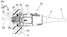
- the principal part expansion perspective view which expands and shows the endoscope connector (plug connector) by the side of an endoscope among the connectors in the endoscope system of FIG.
- the principal part expanded sectional view which shows the connector in the endoscope system of FIG.
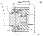
- Sectional drawing which shows notionally the structure of the non-fitting state of the plug connector and receptacle connector in the connector for medical devices of the 1st Embodiment of this invention.
- Sectional drawing which shows notionally the structure of the fitting state of the plug connector and receptacle connector in the connector for medical devices of FIG.
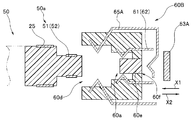
- Sectional drawing which shows notionally the structure of the non-fitting state of the plug connector and receptacle connector in the connector for medical devices of the 2nd Embodiment of this invention.
- Sectional drawing which shows notionally the structure of the fitting state of the plug connector and receptacle connector in the connector for medical devices of FIG.
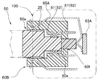
- Sectional drawing which shows notionally the structure of the non-fitting state of the plug connector and receptacle connector in the connector for medical devices of the 3rd Embodiment of this invention.
- Sectional drawing which shows notionally the structure of the fitting state of the plug connector and receptacle connector in the connector for medical devices of FIG.
- a connector refers to a connecting component used to form an electronic circuit by connecting wiring in an electronic circuit, for example.
- This connector includes a plug connector and a receptacle connector.
- the plug connector refers to a so-called male part disposed at the end of a long cable.
- the receptacle connector refers to a so-called female part installed on the surface of a switchboard such as an external device.
- a connector applied to a medical device such as an endoscope system is particularly referred to as a medical device connector.
- FIGS. 1 to 3 a schematic configuration of an endoscope system will be described with reference to FIGS. 1 to 3 as an example of a medical device to which a medical device connector is applied.
- FIG. 1 is a schematic configuration diagram showing an overall configuration of an endoscope system to which the present invention is applied.
- FIG. 2 is an enlarged perspective view of an essential part showing an endoscope connector (plug connector) on the endoscope side among the connectors in the endoscope system to which the present invention is applied.
- FIG. 3 is a cross-sectional view showing a connector in an endoscope system to which the present invention is applied.
- the endoscope connector (plug connector) on the endoscope side in FIG. 2 is fitted to the receptacle connector on the external device side. It is a principal part expanded sectional view which shows the state which has connected.
- an endoscope system 1 as a medical device is mainly configured by an endoscope 5, a light source device 6 and a video processor 7 as external devices, a color monitor 8 as a display device, and the like.
- the endoscope 5 includes an insertion unit 2, an operation unit 3, a universal cable 4, and the like.
- An endoscope connector 50 is provided at the distal end of the universal cable 4.
- the endoscope connector 50 is configured in the form of a plug connector (male side).
- the endoscope connector 50 is detachably connected to the light source device 6 that is an external device. Therefore, the light source device 6 that is an external device in the endoscope system that is a medical device is configured to include a plurality of receptacle connectors 60 (female side) as medical device connectors (two in the example of FIG. 1). ing.
- the insertion portion 2 is an elongated long member that is inserted into a site to be observed.
- the insertion portion 2 is configured by connecting a distal end portion 2a, a bending portion 2b, and a flexible tube portion 2c.
- the distal end portion 2a incorporates an illumination optical system including a light guide (not shown), an imaging device including an imaging element, and the like.
- the bending portion 2b is configured to bend in four directions, for example, up, down, left, and right.
- the flexible tube portion 2c is a long and flexible tubular member.
- the operation unit 3 is configured by combining a first exterior body 11 and a second exterior body 12.
- a treatment instrument insertion port 13 is provided in the first exterior body 11.
- a proximal end portion of the insertion portion 2 is integrally connected and fixed to the distal end side of the first exterior body 11 via a bend preventing member 10.
- the second exterior body 12 is provided with a bending operation section 14, various switches 15, an air / water supply button 16, a suction button 17, and the like.
- the bending operation section 14 is provided with bending operation knobs 14a and 14b for operating the bending section 2b. For example, when the surgeon rotates the bending operation knob 14a in a predetermined direction, a bending wire (not shown) is pulled and relaxed, and the bending portion 2b is bent upward.
- the various switches 15 are, for example, a release switch, a freeze switch, and an observation mode changeover switch for switching between normal observation and fluorescence observation.
- the endoscope connector 50 is provided at the distal end side end portion of the universal cable 4 and is configured to be detachable from the receptacle connector 60 provided on the front surface of the light source device 6 that is an external device. Plug connector.
- the endoscope connector 50 is a connection part for transmitting a light source light beam, an electric signal, and the like by being connected to the endoscope 5 and an external device (the light source device 6, the video processor 7, etc.). . Therefore, the electric cable 18 extends from the side surface of the endoscope connector 50.
- the electrical cable 18 is connected to the video processor 7 via a processor connector 19.
- the base end side of the endoscope connector 50 that is, the portion connected to the universal cable 4 is covered with the outer peripheral portion of the universal cable 4 to maintain the connection strength, and the cable 4 is damaged by twisting or the like.
- a bend-preventing member 9 is provided to prevent this.
- the endoscope connector 50 includes two electrical connector portions 50b and 50c that are formed in two steps in a row from the distal end side, have different outer diameters, are substantially cylindrical, and are integrally formed.
- the electric plug portion 50a, the electric connector portion 50c on the proximal end side, and a substantially cylindrical shape are formed mainly by a connector case 50e that is an exterior member of the endoscope connector 50, a bend preventing member 9, and the like. ing.
- the two electric connector portions 50b and 50c constituting the electric plug portion 50a include an electric connector portion (hereinafter referred to as a first electric connector portion) 50b on a distal end side and an electric connector portion (hereinafter referred to as a second electric connector portion) on the base end side.
- the diameter is smaller than 50c.
- the first electrical connector portion 50b is formed so as to protrude from the end surface of the second electrical connector portion 50c. And in the partial area
- the second electrical connector portion 50c also has a plurality of second electrical contacts 52 (corresponding to communication terminals described later) partially exposed in the circumferential direction in a partial region of the peripheral surface of the outer peripheral portion. Along the line.
- the connector case 50e is provided with a plurality of base members, such as a water supply base, a pressure pipe base, a front water supply base, a suction base, a water leak detection base, etc. (not shown in particular) on the outer surface side (FIG. 2, FIG. 2). 3).
- base members such as a water supply base, a pressure pipe base, a front water supply base, a suction base, a water leak detection base, etc. (not shown in particular) on the outer surface side (FIG. 2, FIG. 2). 3).
- the above-described folding preventing member 9 is provided on the proximal end side of the connector case 50e, and the universal cable 4 is inserted into the folding preventing member 9 and introduced into the endoscope connector 50. .
- an electrical component such as an electronic circuit board is housed and arranged, and fluid piping (air supply / water supply conduit)
- An optical transmission member (light guide cable) or the like is inserted.
- the connector case 50e is formed with cutout portions at two outer peripheral edges on the upper and lower ends of one end thereof (portion between the electric plug portion 50a).
- a flange portion 25 (corresponding to a ground terminal described later), which is a part of the frame member, is exposed to the outside.
- the flange portion 25 is connected to the ground connection terminal 65 of the receptacle connector 60 when the endoscope connector 50 is fitted and connected to a receptacle connector 60 of the light source device 6 (external device) described later.
- the ground of the endoscope 5 and the light source device 6 (external device) is configured to be connected.
- the electric contacts (51, 52) of the two electric connector portions (50b, 50c) and the electric contacts (51, 52) are electrically connected.
- a plurality of contact pins that are electrically connected to each other and a plurality of electric boards (all of which are not shown) to which the plurality of contact pins are fixed by soldering are disposed. Note that the details of the internal structure of the electric plug portion 50a are not directly related to the present invention, and thus detailed description and illustration thereof are omitted. As described above, the endoscope system 1 is configured.
- an embodiment of an endoscope connector 50 configured in the form of a plug connector and a receptacle connector 60 as a medical device connector in the light source device 6 (external device) is described. The details will be described below.
- FIG. 4 and 5 are cross-sectional views conceptually showing the structure of the medical device connector according to the first embodiment of the present invention.
- FIG. 4 shows a non-fitted state in which the plug connector is not fitted to the receptacle connector in the medical device connector of the present embodiment.
- FIG. 5 shows a connection state in which the plug connector is fitted to the receptacle connector in the medical device connector of the present embodiment.
- the medical device connector according to the present embodiment is provided on the endoscope 5 side and has a male plug connector configuration and a female provided on the light source device 6 (external device) side.
- Side receptacle connector 60 is provided on the endoscope 5 side and has a male plug connector configuration and a female provided on the light source device 6 (external device) side.
- the endoscope connector 50 includes a first electrical connector portion 50b having a plurality of first electrical contacts 51 and a second electrical connector portion 50c having a plurality of second electrical contacts 52, and further a portion connected to the ground. And a flange portion 25 (grounding terminal) which is a part of a metal frame member.
- the plurality of first electrical contacts 51 and the plurality of second electrical contacts 52 are both terminal portions for transmitting and communicating data, and are used for the endoscope 5 and external devices (light source device 6, video processor 7).
- a communication terminal for performing data communication with the communication terminal that is, a communication terminal.
- the flange portion 25 is a part of a metal frame member, and is a ground terminal in order to reduce noise during data communication by being grounded.
- the endoscope connector 50 that is, the structural members (the light guide base 50f and the air supply base 50g) extending from the end surface of the first electrical connector 50b are shown.
- the shape of the endoscope connector 50 is conceptually illustrated.
- the plurality of electrical contacts (51, 52) and the corresponding communication contact terminals (61, 62) of the two electrical connector portions (50b, 50c) described above are simplified and combined into one. (See reference numerals 51 and 61).
- the receptacle connector 60 is a connector (connecting part) that is provided on the front surface of the light source device 6 (external device) and is configured to be fitted with the endoscope connector 50 (plug connector).
- the receptacle connector 60 includes an opening 60d, a fitting portion 60a, a grounding portion 63, a communication contact terminal 61, and a ground connection terminal 65.
- the opening 60d is an opening that is formed in the board surface on the front side of the light source device 6 (external device) to communicate the outside with the inside.
- the opening 60d has a diameter that can receive at least the outer diameter portion of the flange portion 25 of the endoscope connector 50 (plug connector).
- an inward flange portion 60c formed so as to protrude toward the inner side in the radial direction of the opening portion 60d is provided at the inner edge portion of the opening portion 60d.
- the inward flange portion 60c is formed so as not to obstruct insertion of the endoscope connector 50 into the opening 60d when the endoscope connector 50 is fitted to the receptacle connector 60.
- the inward flange portion 60c suppresses entry of foreign matter and the like into the opening portion 60d when the endoscope connector 50 is not fitted into the receptacle connector 60, and foreign matter and the like that have entered through the opening portion 60d are grounded. It is provided to prevent the ground connection terminal 65 from contacting the ground portion 63 by acting on the connection terminal 65 and deforming it.
- the fitting portion 60 a is a portion that can be fitted to the endoscope connector 50 (plug connector) corresponding to the endoscope connector 50.
- the fitting portion 60a is formed to correspond to the shape of the electrical connector portion 50a.
- the grounding portion 63 is a component that grounds the flange portion 25 (grounding terminal) by being electrically connected.
- the ground portion 63 is made of a conductive member such as metal connected to an internal ground circuit (a ground portion that is a reference potential point) in the housing of the light source device 6 that is an external device.
- the grounding part 63 is the vicinity of the outer peripheral side of the fitting part 60a, and extends in the direction along the insertion direction when the endoscope connector 50 is fitted to the receptacle connector 60. It is arranged.
- the communication contact terminal 61 is electrically connected to the electrical contact 51 (communication terminal) when the endoscope connector 50 is fitted to the fitting portion 60a. It is.
- the communication contact terminal 61 is connected to an internal electronic circuit of the light source device 6 which is an external device or an internal electronic circuit of the video processor 7 which is an external device connected via the electrical cable 18 and the processor connector 19. .
- the communication contact terminal 61 is formed so that it can be deformed by the stress of the endoscope connector 50 (plug connector) when the receptacle connector 60 and the endoscope connector 50 (plug connector) are fitted. Therefore, the communication contact terminal 61 is formed of, for example, an elastic thin plate-like or linear metal material and is formed to be elastically deformable.
- the communication contact terminal 61 is entirely disposed inside the receptacle connector 60, and a part thereof is disposed so as to project inward from the inner wall surface of the fitting portion 60a.
- the communication contact terminal 61 is configured to deform and move in a direction substantially orthogonal to the insertion direction when the endoscope connector 50 is fitted to the receptacle connector 60.
- ground connection terminal 65 is provided.
- the ground connection terminal 65 is in a non-contact state with respect to the ground portion 63 in a non-fitted state (normal state) where the endoscope connector 50 (plug connector) is not fitted to the receptacle connector 60.
- the ground connection terminal 65 is connected to the endoscope connector 50 (when the electrical plug portion 50 a of the endoscope connector 50 (plug connector) is fitted to the fitting portion 60 a of the receptacle connector 60. It is configured to be deformed by the stress caused by the plug connector) and to be electrically connected to the grounding portion 63.
- the ground connection terminal 65 constitutes a so-called finger terminal formed of, for example, an elastic thin plate or linear metal material so as to be elastically deformable.
- the entire ground connection terminal 65 is disposed inside the receptacle connector 60, and a part of the ground connection terminal 65 is disposed so as to protrude inward from the inner wall surface of the second fitting portion 60b.
- the ground connection terminal 65 is also configured to deform and move in a direction substantially perpendicular to the insertion direction when the endoscope connector 50 is fitted to the receptacle connector 60.
- the ground connection terminal 65 and the ground portion 63 are in a non-contact state. is there. That is, when the fitting connection between the endoscope connector 50 in the form of the plug connector and the receptacle connector 60 is released, it serves to electrically separate the grounding portion 63 and the flange portion 25 (grounding terminal). Yes.
- the receptacle connector 60 in a state before the two are fitted together, the receptacle connector 60 is in a normal state, and at this time, as described above, the ground connection terminal 65 and the ground portion 63 are in a non-contact state.
- the electric plug portion 50a enters from the opening 60d to the fitting portion 60a from this state, when the electric contact 51 contacts the communication contact terminal 61 and further pushes in the endoscope connector 50, the electric plug portion 50a is Then, while maintaining the contact state between the electrical contact 51 and the communication contact terminal 61, the communication contact terminal 61 is further deformed and further entered.
- the flange portion 25 contacts the ground connection terminal 65 in the fitting process.
- the electric plug portion 50a enters further into the back while deforming the ground connection terminal 65 while maintaining the contact state between the flange portion 25 and the ground connection terminal 65.
- the ground connection terminal 65 is deformed in conjunction with this, and a part of the ground connection terminal 65 approaches the ground portion 63.
- the electrical plug portion 50a is completely fitted and connected to the fitting portion 60a, the ground connection terminal 65 contacts the ground portion 63.
- the flange portion 25 (ground terminal) is electrically connected to the ground portion 63 via the ground connection terminal 65.
- the fitted state is released, so that the ground connection terminal 65 and the ground part 63 are in a non-contact state. Therefore, the grounding portion 63 and the flange portion 25 (grounding terminal) are electrically separated. Then, when the electric plug portion 50a is completely fitted and connected to the fitting portion 60a, the ground connection terminal 65 and the ground portion 63 come into contact with each other, whereby the ground portion 63 and the flange portion 25 (ground terminal). Is electrically connected through the ground connection terminal 65.
- the state at this time is the state shown in FIG.
- an electromagnetic shield is formed in a region indicated by reference numeral 100 in FIG. 5 in a peripheral region including a connection portion between the electrical contact 51 (communication terminal) and the communication contact terminal 61.
- the electromagnetic shield 100 is formed as a noise shielding shield by connecting a ground connection terminal 65 and a ground portion 63 provided on the receptacle connector 60 side and a flange portion 25 on the endoscope connector 50 side. Is.
- the flange portion 25 of the endoscope connector 50 and the receptacle connector 60 are grounded.
- the grounding portion 63 is connected via the terminal 65 to form an electromagnetic shield.
- the ground connection terminal 65 of the receptacle connector 60 is grounded. Since the part 63 is in a non-contact state and is not connected, the ground connection terminal 65 can be in a state where it is not grounded.
- the ground connection terminal 65 is configured to be deformed by stress due to the electric plug portion 50a of the endoscope connector 50 when the endoscope connector 50 (plug connector) is fitted to the receptacle connector 60, the endoscope connection 50
- the ground connection terminal 65 can be electrically connected to the ground portion 63 simply by inserting and fitting the connector 50 (plug connector) into the receptacle connector 60.
- the medical device such as the endoscope system 1 and the like and the external device (the light source device 6, the video processor 7, etc.) provided with the plurality of receptacle connectors 60.
- the plug connector endoscope connector 50
- the ground connection terminal 65 and the flange portion 25 ground terminal
- a ground connection terminal 65 provided in the fitting portion on the receptacle connector 60 side and an internal ground circuit (a ground portion which is a reference potential point)can be electrically separated.
- the endoscope connector 50 can be handled without any particular structural change. Therefore, it is possible to apply the endoscope connector of the existing form as it is.
- FIG. 6 shows a non-fitted state in which the plug connector is not fitted to the receptacle connector in the medical device connector of the present embodiment.
- FIG. 7 shows a connection state in which the plug connector is fitted to the receptacle connector in the medical device connector of the present embodiment.
- the basic configuration of the medical device connector of the present embodiment is substantially the same as that of the first embodiment.
- the endoscope connector 50A having a male plug connector provided on the endoscope 5 side is configured such that a pressing projection 50h projects from the distal end of the electric plug 50a.
- the pressing protrusion 50h is a rod-shaped portion formed so as to protrude in the insertion direction when the endoscope connector 50A is fitted to the receptacle connector 60A.
- the arrangement, shape, and size of the pressing protrusion 50h are formed so that the pressing protrusion 50h can be inserted into a through hole 60f (described later) formed in the bottom surface of the fitting portion 60a.
- Other configurations of the endoscope connector 50A are the same as those in the first embodiment.
- the configuration of the female-side receptacle connector 60A provided on the light source device 6 (external device) side is slightly different. Therefore, about the structure substantially the same as the above-mentioned 1st Embodiment, the same code
- the receptacle connector 60A is provided on the front surface of the light source device 6 (external device; see FIG. 1), as in the first embodiment. It is a connector (part for connection) comprised so that connector 50A can be fitted.
- the receptacle connector 60A includes an opening 60d, a fitting portion 60a, a grounding portion 63A, a communication contact terminal 61, and a ground connection terminal 65A.
- the opening 60d is the same opening as in the first embodiment.
- the inward flange part 60c in the above-mentioned 1st Embodiment is not provided. This is because, in the configuration of the present embodiment, even when a foreign object or the like entering from the opening 60d acts on the ground connection terminal 65A when the endoscope connector 50A is not fitted to the receptacle connector 60A, the ground connection Since there is no possibility that the terminal 65A contacts the grounding portion 63A, the inward flange portion 60c is unnecessary.
- the fitting portion 60a is formed in the same manner as in the first embodiment.
- a through hole 60f is further drilled in the bottom surface portion of the fitting portion 60a on the distal end side.
- the through hole 60f is formed as a through hole through which the pressing protrusion 50h on the endoscope connector 50A side is inserted when the endoscope connector 50A is fitted into the receptacle connector 60A.
- the functional part that the grounding part 63A is a constituent member that grounds the flange part 25 (grounding terminal) as a connection target by being electrically connected is the same as that of the first embodiment.
- the grounding portion 63A is made of a conductive member such as a metal connected to an internal grounding circuit (a ground portion which is a reference potential point) in the housing of the light source device 6 (external device).
- an internal grounding circuit a ground portion which is a reference potential point
- the receptacle connector 60A The same applies to the point of being disposed in the vicinity of the fitting portion 60a.
- the grounding portion 63A is in the vicinity of the fitting portion 60a in the receptacle connector 60A, and is a deepened position along the insertion direction when the endoscope connector 50A is fitted to the receptacle connector 60A. And fixed at a position facing the through hole 60f.
- the communication contact terminal 61 is configured in exactly the same manner as in the first embodiment described above.
- the ground connection terminal 65A is electrically connected to the ground portion 63A and the flange portion 25 (ground terminal) in conjunction with the fitting of the fitting portion 60a and the endoscope connector 50A.
- the functional aspect of being a terminal member interposed between the grounding portion 63A and the flange portion 25 (grounding terminal) is the same as in the first embodiment.
- the ground connection terminal 65A has a contact portion whose one end protrudes on the inner peripheral surface of the fitting portion 60a and contacts the flange portion 25 (ground terminal).
- the other end is disposed so as to extend around the receptacle connector 60A, and the other end is disposed in the space between the grounding portion 63A and the through hole 60f in the vicinity of the grounding portion 63A.
- the other end of the ground connection terminal 65A is formed in a cantilever shape, and is configured to be elastically deformable in the insertion direction when the endoscope connector 50A is fitted to the receptacle connector 60A. Yes.
- the ground connection terminal 65A has a pressing protrusion at the tip of the endoscope connector 50A when the electric plug portion 50a of the endoscope connector 50A is fitted to the fitting portion 60a of the receptacle connector 60A. It is configured to be deformed by being pressed by the portion 50h and to be electrically connected to the grounding portion 63A.
- the ground connection terminal 65A is formed of, for example, an elastic thin plate or linear metal material.
- the ground connection terminal 65A is arranged in such a manner that a part on one end side protrudes inward from the inner wall surface of the second fitting portion 60b, and when the endoscope connector 50A is fitted to the receptacle connector 60A. It is configured to be deformed and moved in a direction substantially perpendicular to the insertion direction. Further, as described above, a part of the ground connection terminal 65A on the other end side is inserted in the space between the grounding portion 63A and the through hole 60f when the endoscope connector 50A is fitted to the receptacle connector 60A. It is arranged so that it can be elastically deformed.
- the ground connection terminal 65A and the ground portion 63A are not in contact with each other. In contact. That is, when the fitting connection between the endoscope connector 50A and the receptacle connector 60A is released, the grounding portion 63A and the flange portion 25 are electrically separated.
- the receptacle connector 60A is in a normal state before the two are fitted together, and at this time, the other end of the ground connection terminal 65A and the ground portion 63A are in a non-contact state (FIG. 6).
- the electric plug portion 50a enters from the opening 60d to the fitting portion 60a from this state, when the electric contact 51 contacts the communication contact terminal 61 and further pushes in the endoscope connector 50A, the electric plug portion 50a is Then, while maintaining the contact state between the electrical contact 51 and the communication contact terminal 61, the communication contact terminal 61 is further deformed and further entered.
- action of the communication contact terminal 61 and the electrical contact 51 so far is the same as that of the above-mentioned 1st Embodiment.
- the flange portion 25 comes into contact with the ground connection terminal 65A. Then, when the endoscope connector 50A is further pushed in, the electric plug portion 50a further goes back while deforming the ground connection terminal 65A while maintaining the contact state between the flange portion 25 and one end of the ground connection terminal 65A. And enter.
- the endoscope connector 50A when the endoscope connector 50A is further pushed in, the pressing protrusion 50h at the tip of the electric plug portion 50a of the endoscope connector 50A is inserted into the through hole 60f. Then, the tip of the pressing protrusion 50h comes into contact with the other end of the ground connection terminal 65A, and this is pressed and deformed. Then, the other end of the ground connection terminal 65A approaches the ground part 63A. Eventually, when the electric plug portion 50a is completely fitted and connected to the fitting portion 60a, the other end of the ground connection terminal 65A comes into contact with the ground portion 63A. Thereby, the flange portion 25 (ground terminal) is electrically connected to the ground portion 63A via the ground connection terminal 65A.
- an electromagnetic shield is provided in an area indicated by reference numeral 100 in FIG. 7 in the surrounding area including the connection portion between the electrical contact 51 (communication terminal) and the communication contact terminal 61, as in the first embodiment. It is formed.
- the pressing protrusion 50h at the tip of the electric plug portion 50a of the endoscope connector 50A has the through hole 60f.
- the other end of the ground connection terminal 65A that has been inserted through is pushed by the tip of the pressing projection 50h, and is deformed so as to come into contact with the ground 63A.
- the endoscope connector 50A also involves some structural changes.
- FIG. 8 and 9 are sectional views conceptually showing the configuration of the medical device connector according to the third embodiment of the present invention.
- FIG. 8 shows a non-fitted state in which the plug connector is not fitted into the receptacle connector in the medical device connector of the present embodiment.
- FIG. 9 shows a connection state in which the plug connector is fitted to the receptacle connector in the medical device connector of the present embodiment.
- the basic configuration of the medical device connector of the present embodiment is substantially the same as that of the above-described embodiments.
- the endoscope connector 50 having a male plug connector provided on the endoscope 5 side has the same configuration as that of the first embodiment described above. Therefore, the description of the configuration is omitted.
- the configuration of the female-side receptacle connector 60B provided on the light source device 6 (external device) side is slightly different. Therefore, about the structure substantially the same as each above-mentioned embodiment, the same code
- the receptacle connector 60B is provided on the front surface of the light source device 6 (external device; see FIG. 1), as in the second embodiment, and the endoscope It is a connector (part for connection) comprised so that the connector 50 can be fitted.
- the receptacle connector 60B includes an opening 60d, a fitting portion 60a, a grounding portion 63A, a communication contact terminal 61, and a ground connection terminal 65A.
- the opening 60d has the same configuration as that of the second embodiment described above. Therefore, in the opening 60d of the present embodiment, the inward flange portion 60c in the first embodiment described above is not provided. This is unnecessary for the same reason as the configuration of the second embodiment described above.
- the fitting portion 60a is formed in the same manner as in the second embodiment. Also in the present embodiment, a through hole 60f is formed in the bottom surface portion of the fitting portion 60a, as in the second embodiment described above. In the present embodiment, the through-hole 60f is further movable in the through-hole 60f so as to protrude and retract along the through-direction of the through-hole 60f, that is, the insertion direction when the endoscope connector 50 is fitted to the receptacle connector 60B. 60e is arranged.
- the moving member 60e When the endoscope connector 50 is fitted into the receptacle connector 60B, the moving member 60e is pressed by the distal end of the endoscope connector 50, thereby pressing and deforming the other end of the ground connection terminal 65A to the ground portion 63A. It is an intermediate member that is interposed to connect with.
- the moving member 60e is not shown in the normal state (non-fitted state) shown in FIG. 9 so as to be disposed at a position protruding inside the fitting part 60a. It is urged by the urging means in the direction of arrow X1 in FIG. With this configuration, the moving member 60e contacts the communication contact terminal 61 unintentionally with a finger of a person such as a user (user) or a conductor such as various appliances when not engaged. It also serves to prevent this.
- the grounding part 63A, the communication contact terminal 61, and the ground connection terminal 65A have the same configuration as that of the second embodiment.
- the moving member 60e moves in the direction of arrow X2 in FIG. 8, presses the other end of the ground connection terminal 65A, and deforms it, thereby connecting the other end of the ground connection terminal 65A to the ground portion 63A. And make an electrical connection.
- the receptacle connector 60B is in a normal state before the two are fitted, and at this time, the other end of the ground connection terminal 65A and the ground portion 63A are in a non-contact state (FIG. 8).
- the electric contact 51 contacts the communication contact terminal 61.
- the connection action between the communication contact terminal 61 and the electrical contact 51 at this time is the same as in the first and second embodiments described above.
- the flange portion 25 comes into contact with the ground connection terminal 65A. Then, when the endoscope connector 50 is further pushed in, the electric plug portion 50a further goes back while deforming the ground connection terminal 65A while maintaining the contact state between the flange portion 25 and one end of the ground connection terminal 65A. And enter.
- the distal end of the endoscope connector 50 comes into contact with the moving member 60e disposed in the through hole 60f and presses it. Then, the moving member 60e moves in the through hole 60f in the direction of the arrow X2 in FIG. 8, and the distal end of the moving member 60e comes into contact with the other end of the ground connection terminal 65A, which is pressed and deformed. Then, the other end of the ground connection terminal 65A approaches the ground part 63A. Eventually, when the electric plug portion 50a is completely fitted and connected to the fitting portion 60a, the other end of the ground connection terminal 65A comes into contact with the ground portion 63A. Thereby, the flange portion 25 (ground terminal) is electrically connected to the ground portion 63A via the ground connection terminal 65A.
- an electromagnetic shield is formed in a region indicated by reference numeral 100 in FIG. 9 in the peripheral region including the connection portion between the electrical contact 51 (communication terminal) and the communication contact terminal 61, as in the above-described embodiments.
- the same effects as those of the above-described embodiments can be obtained. Further, according to the present embodiment, as in the first embodiment described above, since there is no structural change with respect to the endoscope connector 50, the endoscope connector of the existing form is applied as it is. Can do.
- the present invention is not limited to the above-described embodiment, and it is needless to say that various modifications and applications can be implemented without departing from the spirit of the invention.
- the above embodiments include inventions at various stages, and various inventions can be extracted by appropriately combining a plurality of disclosed constituent elements. For example, even if several constituent requirements are deleted from all the constituent requirements shown in the above-described embodiment, if the problem to be solved by the invention can be solved and the effect of the invention can be obtained, this constituent requirement is deleted.
- the configured structure can be extracted as an invention.
- constituent elements over different embodiments may be appropriately combined. The invention is not limited by the specific embodiments thereof, except as limited by the appended claims.
- the present invention can be applied not only to an endoscope apparatus in the medical field but also to an endoscope apparatus in the industrial field.
Landscapes
- Health & Medical Sciences (AREA)
- Life Sciences & Earth Sciences (AREA)
- Surgery (AREA)
- Physics & Mathematics (AREA)
- Optics & Photonics (AREA)
- Engineering & Computer Science (AREA)
- Biophysics (AREA)
- Animal Behavior & Ethology (AREA)
- Pathology (AREA)
- Radiology & Medical Imaging (AREA)
- Veterinary Medicine (AREA)
- Biomedical Technology (AREA)
- Heart & Thoracic Surgery (AREA)
- Medical Informatics (AREA)
- Molecular Biology (AREA)
- Nuclear Medicine, Radiotherapy & Molecular Imaging (AREA)
- General Health & Medical Sciences (AREA)
- Public Health (AREA)
- Mechanical Engineering (AREA)
- Astronomy & Astrophysics (AREA)
- General Physics & Mathematics (AREA)
- Endoscopes (AREA)
- Instruments For Viewing The Inside Of Hollow Bodies (AREA)
Abstract
本発明は、レセプタクルとプラグとの非嵌合時に接地接続端子と内部接地回路とを電気的に分離させ得る構造の医療機器用コネクタを提供することを目的とし、そのために、本発明の医療機器用コネクタは、通信端子51と接地端子52とを有するプラグ50を嵌合可能な嵌合部60aを有するコネクタ60であって、嵌合部近傍に設けられ電気的に接続された接続対象を接地する接地部63と、嵌合部に設けられ嵌合部とプラグとが嵌合された時に通信端子と電気的に接続される通信接点端子61と、嵌合部に設けられ嵌合部とプラグとの嵌合に連動して接地部と接地端子とを電気的に接続させる接地接続端子65とを備え、プラグとコネクタとを嵌合接続した時には接地端子と接地部とは接地接続端子を介して接続され、プラグとコネクタとの嵌合接続を解除した時には接地端子と接地部とは電気的に分離される。
Description
この発明は、内視鏡等のプラグコネクタを嵌合接続可能とするレセプタクルコネクタを複数具備する医療機器に適用される医療機器用コネクタに関するものである。
従来、細長状に形成された挿入部を有して構成される内視鏡は、例えば医療分野や工業用分野等において広く利用されている。このうち、医療分野において用いられる医療用内視鏡は、細長い挿入部を被検体となる体腔内に挿入して体腔内の臓器を観察したり、必要に応じて内視鏡に具備される処置具挿通チャンネル内に挿入した処置具を用いて各種の処置を施すことができるように構成されている。また、工業分野において用いられる工業用内視鏡は、細長い挿入部を被検体、例えばジェットエンジンや工場配管等の内部に挿入することによって、被検体内の状態、例えば傷及び腐蝕等の観察や検査を行うことができるように構成されている。
この種の内視鏡は、例えばビデオプロセッサや光源装置等の外部装置(医療機器)に接続されて、これらと協働することによって内視鏡システムが構築される。そのために、当該内視鏡システムにおいて、上記内視鏡は、当該内視鏡から延出される各種信号ケーブル,ライトガイドケーブル等を束ねたいわゆるユニバーサルケーブルの終端にプラグコネクタを有して構成されている。また、これに対応させて、上記外部装置は、上記内視鏡側のプラグコネクタを着脱可能とし、当該プラグコネクタが嵌合接続された時には、上記内視鏡と上記外部装置との間の電気的な接続を確保するレセプタクルコネクタを有して構成されている。なお、内視鏡システム等の医療機器に適用されるコネクタを、特に医療機器用コネクタと称している。
一般に医療機器用コネクタにおいては、プラグコネクタとレセプタクルコネクタとを嵌合接続した時に、プラグコネクタ側に設けた接地端子(グランド端子)とレセプタクルコネクタ側に設けた接地接続端子(フィンガー端子)とが接触してレセプタクルコネクタ側の接地部に接地されることによって、通信用接点の接続部分を電磁的に遮蔽する電磁シールドを形成し、これによって放射ノイズ等の発散を抑止する構成を備えている。
例えば、国際公開番号WO2011/052408号公報等によって開示されている医療機器用コネクタは、プラグコネクタ側に設けられた金属製部品とレセプタクルコネクタ側に設けられた金属部品とが、互いに嵌合して接触することで、内視鏡及び外部機器とのグランドが接続されるように構成している。
ところで、近年の内視鏡システム等の医療機器においては、外部装置側(ビデオプロセッサや光源装置等)にレセプタクルコネクタを複数具備して構成されていながら、内部接地回路を共通とする構成のものが実用化されている。
このような形態の医療機器においては、例えば外装装置における複数のレセプタクルコネクタのうちの一方にプラグコネクタが嵌合接続されており、他方のレセプタクルコネクタにはプラグコネクタが嵌合されていない状態、つまり空き状態のまま実用に供される場合がある。
この場合、プラグコネクタが非接続状態にあるレセプタクルコネクタは、嵌合部が開口していることから、例えば使用者(ユーザ)等の人物の手指等や各種の器具類等の導電体が意図せずに挿入されてしまう可能性がある。したがって、レセプタクルコネクタとプラグコネクタとが嵌合していない状態においては、レセプタクルコネクタ側の嵌合部内に設けられる接地接続端子と内部接地回路とが電気的に絶縁状態になっていることが望ましい。
ところが、上記国際公開番号WO2011/052408号公報等によって開示されているような形態の従来構成の医療機器用コネクタの構成を、レセプタクルコネクタを複数具備する構成の外部装置に適用する場合、プラグコネクタが非嵌合接続時において、レセプタクルコネクタ側の接地接続端子(フィンガー端子)に接触不可能とする構造を実現することは困難である。
本発明は、上述した点に鑑みてなされたものであって、その目的とするところは、内視鏡システム等の医療機器であって、複数のレセプタクルコネクタを備えた外部装置において、レセプタクルコネクタとプラグコネクタとの嵌合接続時には電磁シールドを形成し、レセプタクルコネクタとプラグコネクタとの非嵌合時には、レセプタクルコネクタ側の嵌合部内に設けられる接地接続端子と内部接地回路(基準電位点であるグランド部)とを電気的に分離させ得る構造の医療機器用コネクタを提供することである。
上記目的を達成するために、本発明の一態様の医療機器用コネクタは、データを通信するための通信端子と、接地されることでデータ通信時のノイズを低減するための接地端子と、を有するプラグコネクタを嵌合可能な嵌合部、を有するコネクタであって、前記嵌合部の近傍に設けられ、電気的に接続されることで接続対象を接地する接地部と、前記嵌合部に設けられ、前記嵌合部と前記プラグコネクタとが嵌合された時に前記通信端子と電気的に接続される通信接点端子と、前記嵌合部に設けられ、前記嵌合部と前記プラグコネクタとの嵌合に連動して前記接地部と前記プラグコネクタ側の前記接地端子とを電気的に接続させる接地接続端子と、を具備し、前記プラグコネクタと前記コネクタとを嵌合接続した時には、前記接地端子と前記接地部とは前記接地接続端子を介して接続され、前記プラグコネクタと前記コネクタとの嵌合接続を解除した時には、前記プラグコネクタ側の前記接地端子と前記コネクタ側の前記接地部とは電気的に分離される。
本発明によれば、内視鏡システム等の医療機器であって、複数のレセプタクルコネクタを備えた外部装置において、レセプタクルコネクタとプラグコネクタとの嵌合接続時には電磁シールドを形成し、レセプタクルコネクタとプラグコネクタとの非嵌合時には、レセプタクルコネクタ側の嵌合部内に設けられる接地接続端子と内部接地回路(基準電位点であるグランド部)とを電気的に分離させ得る構造の医療機器用コネクタを提供することができる。
以下、図示の実施の形態によって本発明を説明する。以下の説明に用いる各図面は模式的に示すものであり、各構成要素を図面上で認識可能な程度の大きさで示すために、各部材の寸法関係や縮尺等を各構成要素毎に異ならせて示している場合がある。したがって、本発明は、これら各図面に記載された構成要素の数量,構成要素の形状,構成要素の大きさの比率,各構成要素の相対的な位置関係等に関し、図示の形態のみに限定されるものではない。
なお、以下の説明において、コネクタとは、例えば電子回路等において配線を接続し電子回路を形成するために用いられる接続用の部品等をいうものとする。このコネクタは、プラグコネクタとレセプタクルコネクタとがある。ここで、プラグコネクタとは、長いケーブルの終端に配設されるいわゆるオス側の部品を称するものである。一方、レセプタクルコネクタとは、外部装置等の配電盤等の表面に設置されるいわゆるメス側の部品を称するものである。なお、以下の説明において、内視鏡システム等の医療機器に適用されるコネクタを、特に医療機器用コネクタと称するものとする。
まず、本発明の各実施形態を詳述する前に、医療機器用コネクタが適用される医療機器の一例として、内視鏡システムの概略構成について、図1~図3を用いて説明する。
図1は、本発明が適用される内視鏡システムの全体構成を示す概略構成図である。図2は、本発明が適用される内視鏡システムにおけるコネクタのうち内視鏡側の内視鏡コネクタ(プラグコネクタ)を拡大して示す要部拡大斜視図である。図3は、本発明が適用される内視鏡システムにおけるコネクタを示す断面図であって、図2の内視鏡側の内視鏡コネクタ(プラグコネクタ)が外部装置側のレセプタクルコネクタに嵌合接続している状態を示す要部拡大断面図である。
図1に示すように、医療機器としての内視鏡システム1は、内視鏡5と、外部装置としての光源装置6及びビデオプロセッサ7と、表示装置であるカラーモニタ8等によって主に構成される。
内視鏡5は、挿入部2と、操作部3と、ユニバーサルケーブル4等を備えて構成されている。ユニバーサルケーブル4の先端側終端部には内視鏡コネクタ50が設けられている。この内視鏡コネクタ50は、プラグコネクタの形態(オス側)に構成されている。内視鏡コネクタ50は、外部装置である光源装置6に対して着脱自在に接続される。そのために、医療機器である内視鏡システムにおける外部装置である光源装置6は、医療機器用コネクタとしてのレセプタクルコネクタ60(メス側)を複数(図1の例では2個)有して構成されている。
内視鏡5において、挿入部2は観察対象部位へ挿入される細長な長尺部材である。挿入部2は、先端部2aと、湾曲部2bと、可撓管部2cとを連設して構成されている。先端部2aにはライトガイド(不図示)を備える照明光学系と、撮像素子を含む撮像装置等が内蔵されている。湾曲部2bは、例えば上下左右の四方向に湾曲するように構成されている。可撓管部2cは、長尺で可撓性を有する管状部材である。
内視鏡5において、操作部3は、第1外装体11と第2外装体12とを組み合わせて構成されている。第1外装体11には例えば処置具挿入口13が設けられている。第1外装体11の先端側には折れ止め部材10を介して挿入部2の基端部が一体に連結固定されている。
第2外装体12には、湾曲操作部14、各種スイッチ15、送気送水ボタン16、吸引ボタン17などが設けられている。湾曲操作部14には、例えば、湾曲部2bを湾曲操作するための湾曲操作ノブ14a、14bが設けられている。術者が、例えば湾曲操作ノブ14aを予め定められた方向に回転させることによって、図示しない湾曲ワイヤーが牽引、弛緩されて湾曲部2bが上方向に湾曲動作する。
各種スイッチ15は、例えば、レリーズスイッチ、フリーズスイッチ及び通常観察と蛍光観察との切替を行うための観察モード切替スイッチ等である。
内視鏡コネクタ50は、上述したように、ユニバーサルケーブル4の先端側終端部に設けられ、外部装置である光源装置6の前面側の盤面に設けられるレセプタクルコネクタ60に対して着脱可能に構成されるプラグコネクタである。この内視鏡コネクタ50は、内視鏡5と外部装置(光源装置6及びビデオプロセッサ7等)に対して接続されることで、光源光束や電気信号等を伝送するための接続用部品である。そのために、内視鏡コネクタ50の側面からは、電気ケーブル18が延出している。この電気ケーブル18は、プロセッサ用コネクタ19を介してビデオプロセッサ7に接続されている。
内視鏡コネクタ50の基端側、即ち上記ユニバーサルケーブル4との連設部分には、当該ユニバーサルケーブル4の外周部を被覆し、その接続強度を維持すると共に、同ケーブル4に対する捩れ等による損傷を防止するための折れ止め部材9が配設されている。
内視鏡コネクタ50は、図2及び図3に示すように、先端側から順に、2段連設形成され外径が異なり略円柱状からなり一体形成された2つの電気コネクタ部50b,50cを有する電気プラグ部50aと、基端側の電気コネクタ部50cに連設され略円筒状からなり当該内視鏡コネクタ50の外装部材であるコネクタケース50eと、折れ止め部材9等によって主に形成されている。
電気プラグ部50aを構成する2つの電気コネクタ部50b,50cは、先端側の電気コネクタ部(以下、第1電気コネクタ部という)50bが基端側の電気コネクタ部(以下、第2電気コネクタ部という)50cよりも小径に形成されている。
第1電気コネクタ部50bは、第2電気コネクタ部50cの端面から突設するように形成されている。そして、第1電気コネクタ部50bの外周部の周面の一部の領域には、複数の第1電気接点51(後述する通信端子に相当する)の一部を外部に露出した形態で周方向に沿って並設されている。また、第1電気コネクタ部50bの端面からは、外部装置からの照明光が入射されるライトガイド口金50fと、外部装置からの気体が送気される送気口金50gとが延設されている。第2電気コネクタ部50cにも、外周部の周面の一部の領域において、複数の第2電気接点52(後述する通信端子に相当する)が一部を外部に露出した形態で周方向に沿って並設されている。
コネクタケース50eは、外面側に複数の口金部材、例えば送水口金,加圧管口金,前方送水口金,吸引口金,漏水検知口金等(特に明示せず)が設けられている(図2,図3参照)。
そして、コネクタケース50eの基端側には、上述した折れ止め部材9が設けられ、この折れ止め部材9には、ユニバーサルケーブル4が挿通し、当該内視鏡コネクタ50の内部に導入されている。
内視鏡コネクタ50の内部には、骨格部品となる金属製のフレーム部材等のほか、電子回路基板等の電気的構成部材が収納配置されていると共に、流体配管(送気送水管路)や光学的伝送部材(ライトガイドケーブル)等が挿通している。
なお、上記コネクタケース50eには、その一端部(上記電気プラグ部50aとの間の部位)の上下2箇所の外周縁辺に切り欠き部が形成されており、これら切り欠き部からは、上記金属製フレーム部材の一部であるフランジ部25(後述する接地端子に相当する)が、外部に向けて露呈している。
このフランジ部25は、当該内視鏡コネクタ50が、後述する光源装置6(外部装置)のレセプタクルコネクタ60に嵌合接続した時に、当該レセプタクルコネクタ60の接地接続端子65に接触することで、内視鏡5と光源装置6(外部装置)とのグランドが接続されるように構成されている。
そして、上記電気プラグ部50aの内部には、2つの電気コネクタ部(50b,50c)の上記複数の電気接点(51,52)と、これら複数の電気接点(51,52)に対して電気的に導通される複数の接点ピンやこれら複数の接点ピンが半田付け固定される複数の電気基板(いずれも不図示)等が配設されている。なお、電気プラグ部50aの内部構造の詳細は、本発明に直接関連しない部分であるので、その詳細説明及び図示は省略する。以上のように内視鏡システム1は構成されている。
このように構成された内視鏡システム1において、プラグコネクタの形態に構成される内視鏡コネクタ50と、光源装置6(外部装置)における医療機器用コネクタとしてのレセプタクルコネクタ60についての実施形態を、以下に詳述する。
[第1の実施形態]
図4,図5は、本発明の第1の実施形態の医療機器用コネクタの構成を概念的に示す断面図である。このうち、図4は、本実施形態の医療機器用コネクタにおいて、プラグコネクタがレセプタクルコネクタに嵌合していない非嵌合状態を示している。また、図5は、本実施形態の医療機器用コネクタにおいて、プラグコネクタがレセプタクルコネクタに嵌合している接続状態を示している。
図4,図5は、本発明の第1の実施形態の医療機器用コネクタの構成を概念的に示す断面図である。このうち、図4は、本実施形態の医療機器用コネクタにおいて、プラグコネクタがレセプタクルコネクタに嵌合していない非嵌合状態を示している。また、図5は、本実施形態の医療機器用コネクタにおいて、プラグコネクタがレセプタクルコネクタに嵌合している接続状態を示している。
本実施形態の医療機器用コネクタは、上述したように、内視鏡5側に設けられオス側のプラグコネクタ形態からなる内視鏡コネクタ50と、光源装置6(外部装置)側に設けられるメス側のレセプタクルコネクタ60とによって構成される。
このうち内視鏡コネクタ50は、複数の第1電気接点51を有する第1電気コネクタ部50bと、複数の第2電気接点52を有する第2電気コネクタ部50cと共に、さらにグランドに接続される部位であり金属製フレーム部材の一部であるフランジ部25(接地端子)を備えている。
上記複数の第1電気接点51,上記複数の第2電気接点52は、共にデータを伝送し通信するための端子部であって、内視鏡5と外部装置(光源装置6,ビデオプロセッサ7)との間でデータ通信を行なう通信用の端子、即ち通信端子である。
また、フランジ部25は、金属製フレーム部材の一部であり、接地されることでデータ通信時のノイズを低減するため接地端子である。
なお、図4,図5において、内視鏡コネクタ50の一部の構成、即ち第1電気コネクタ部50bの端面から延設される構成部材(上記ライトガイド口金50f,送気口金50g)の図示を省略し、内視鏡コネクタ50の形状を概念的に図示している。また、上述した2つの電気コネクタ部(50b,50c)の上記複数の電気接点(51,52)及びこれに対応する通信接点端子(61,62)については、図示を簡略化して一つにまとめて図示している(符号51,61参照)。
一方、レセプタクルコネクタ60は、光源装置6(外部装置)の前面側の盤面に設けられ、上記内視鏡コネクタ50(プラグコネクタ)を嵌合可能に構成されるコネクタ(接続用部品)である。そのために、レセプタクルコネクタ60は、開口部60dと、嵌合部60aと、接地部63と、通信接点端子61と、接地接続端子65とを備えている。
レセプタクルコネクタ60において、上記開口部60dは、光源装置6(外部装置)の前面側の盤面に穿設されて、外部と内部を連通させる開口である。開口部60dは、内視鏡コネクタ50(プラグコネクタ)の少なくともフランジ部25の外径部分を受け入れ可能なサイズの直径を有して形成されている。
なお、開口部60dの内縁部には、当該開口部60dの径方向の内側に向けて突出するように形成される内向フランジ部60cが設けられている。この内向フランジ部60cは、内視鏡コネクタ50のレセプタクルコネクタ60への嵌合時には、内視鏡コネクタ50が開口部60dへ挿入するのを阻害することのないように形成されている。これと同時に、内向フランジ部60cは、内視鏡コネクタ50のレセプタクルコネクタ60への非嵌合時には、開口部60dへの異物等の侵入を抑止すると共に、開口部60dから侵入した異物等が接地接続端子65に作用して、これを変形させ、これにより接地接続端子65が接地部63に接触してしまうことを防止するために設けられている。
上記嵌合部60aは、内視鏡コネクタ50に対応して当該内視鏡コネクタ50(プラグコネクタ)を嵌合可能な部位である。この嵌合部60aは、電気コネクタ部50aの形状に対応するように形成されている。
接地部63は、電気的に接続されることで上記フランジ部25(接地端子)を接地する構成部材である。この接地部63は、外部装置である光源装置6の筐体内の内部接地回路(基準電位点であるグランド部)に接続されている金属等の導電性部材からなる。そして、接地部63は、レセプタクルコネクタ60において、嵌合部60aの外周側近傍であって、内視鏡コネクタ50をレセプタクルコネクタ60に嵌合させる際の挿入方向に沿う方向に延出するように配設されている。
通信接点端子61は、上記嵌合部60aに対し、上記内視鏡コネクタ50が嵌合された状態となったとき、上記電気接点51(通信端子)に対して電気的に接続される端子部材である。そして、通信接点端子61は、外部装置である光源装置6の内部電子回路若しくは電気ケーブル18,プロセッサ用コネクタ19を介して接続される外部装置であるビデオプロセッサ7の内部電子回路に接続されている。通信接点端子61は、レセプタクルコネクタ60と内視鏡コネクタ50(プラグコネクタ)との嵌合時には、内視鏡コネクタ50(プラグコネクタ)による応力によって変形し得るように形成されている。そのために、通信接点端子61は、例えば弾性を有する薄板状若しくは線形状の金属素材によって形成され、弾性変形可能に形成されている。通信接点端子61は、全体がレセプタクルコネクタ60の内部に配設され、一部が嵌合部60aの内壁面より内側に向けて突設した形態で配置されている。そして、通信接点端子61は、内視鏡コネクタ50をレセプタクルコネクタ60に嵌合させる際の挿入方向に略直交する方向に向けて変形移動するように構成されている。
接地接続端子65は、上記嵌合部60aと上記内視鏡コネクタ50との嵌合に連動して、上記接地部63と上記フランジ部25(接地端子)とを電気的に接続させるために、上記接地部63と上記フランジ部25(接地端子)との間に介在する端子部材である。
接地接続端子65は、レセプタクルコネクタ60に内視鏡コネクタ50(プラグコネクタ)が嵌合されていない非嵌合状態(通常状態)においては、接地部63に対し非接触状態にある。一方、接地接続端子65は、レセプタクルコネクタ60の嵌合部60aに内視鏡コネクタ50(プラグコネクタ)の電気プラグ部50aが嵌合された嵌合状態となったときには、内視鏡コネクタ50(プラグコネクタ)による応力によって変形して、接地部63と電気的に接続されるように構成されている。
そのために、接地接続端子65は、例えば弾性を有する薄板状若しくは線形状の金属素材によって形成され弾性変形可能に形成されたいわゆるフィンガー端子を構成している。接地接続端子65は、全体がレセプタクルコネクタ60の内部に配置され、一部が第2嵌合部60bの内壁面より内側に向けて突設した形態で配置されている。そして、接地接続端子65も、内視鏡コネクタ50をレセプタクルコネクタ60に嵌合させる際の挿入方向に略直交する方向に向けて変形移動するように構成されている。
このように構成されたレセプタクルコネクタ60においては、内視鏡コネクタ50が嵌合接続されていない状態にあるときには、図4に示すように、接地接続端子65と接地部63とは非接触状態にある。つまり、プラグコネクタ形態の内視鏡コネクタ50とレセプタクルコネクタ60との嵌合接続が解除されている時には、接地部63と上記フランジ部25(接地端子)とを電気的に分離する役目をしている。
ここで、レセプタクルコネクタ60に内視鏡コネクタ50を嵌合接続する際の作用を詳述する。
まず、図4に示す状態、即ちレセプタクルコネクタ60と内視鏡コネクタ50とが非嵌合状態にあるとき、レセプタクルコネクタ60の開口部60dに対して内視鏡コネクタ50(プラグコネクタ)の先端側の電気プラグ部50aを挿入する。そして、内視鏡コネクタ50の電気プラグ部50aをレセプタクルコネクタ60の嵌合部60aに嵌合させる。
ここで、両者が嵌合する前の状態では、レセプタクルコネクタ60は通常状態にあり、このとき上述したように接地接続端子65と接地部63とは非接触状態にある。この状態から電気プラグ部50aが開口部60dから嵌合部60aへと進入する過程において、電気接点51が通信接点端子61に接触し、さらに内視鏡コネクタ50を押し込むと、電気プラグ部50aは、電気接点51と通信接点端子61との接触状態を維持しながら、通信接点端子61を変形させつつ、さらに奥へと進入する。
同時に、上記嵌合過程において、フランジ部25が接地接続端子65に接触する。そして、内視鏡コネクタ50がさらに押し込まれると、電気プラグ部50aは、フランジ部25と接地接続端子65との接触状態を維持しながら、接地接続端子65を変形させつつ、さらに奥へと進入する。こうして、内視鏡コネクタ50のレセプタクルコネクタ60に対する嵌合が進むにつれて、これに連動して接地接続端子65が変形して、その一部が接地部63に近付く。やがて、電気プラグ部50aが嵌合部60aに対して完全に嵌合接続された状態になったときに、接地接続端子65は接地部63に接触する。これにより、フランジ部25(接地端子)は、接地接続端子65を介して接地部63と電気的に接続される。
ここで、内視鏡コネクタ50とレセプタクルコネクタ60とを嵌合させつつあるときには、嵌合状態は解除されている状態にあるので、接地接続端子65と接地部63とは非接触状態にある。したがって、接地部63と上記フランジ部25(接地端子)とは電気的に分離している。そして、電気プラグ部50aが嵌合部60aに対して完全に嵌合接続されたときに接地接続端子65と接地部63とが接触することで、接地部63と上記フランジ部25(接地端子)とは、接地接続端子65を介して電気的に接続されることになる。このときの状態が図5に示す状態である。
このようにして、図5に示すように、内視鏡コネクタ50(プラグコネクタ)とレセプタクルコネクタ60とが嵌合接続された時には、フランジ部25(接地端子)と接地部63とは接地接続端子65を介して接続される。このとき、上記電気接点51(通信端子)と通信接点端子61との接続部分を含む周囲領域には、図5の符号100で示す領域において電磁シールドが形成される。
上記電磁シールド100は、レセプタクルコネクタ60側に設けられる接地接続端子65,接地部63と、内視鏡コネクタ50側のフランジ部25とが接続されることで、ノイズ遮蔽用のシールドとして形成されるものである。
以上説明したように上記第1の実施形態によれば、内視鏡コネクタ50(プラグコネクタ)とレセプタクルコネクタ60との嵌合時には、内視鏡コネクタ50のフランジ部25とレセプタクルコネクタ60の接地接続端子65を介して接地部63が接続されて電磁シールドが形成される一方、内視鏡コネクタ50(プラグコネクタ)とレセプタクルコネクタ60との非嵌合時には、レセプタクルコネクタ60の接地接続端子65と接地部63とは非接触状態にあって接続されていないので接地接続端子65は接地されない状態とすることができる。
接地接続端子65は、内視鏡コネクタ50(プラグコネクタ)がレセプタクルコネクタ60に嵌合される時に、内視鏡コネクタ50の電気プラグ部50aによる応力によって変形するように構成したので、内視鏡コネクタ50(プラグコネクタ)をレセプタクルコネクタ60に挿入し嵌合させるのみで、接地接続端子65を接地部63に電気的に接続させることができる。
したがって、この構成により、本実施形態の医療機器用コネクタにおいては、内視鏡システム1等の医療機器であって複数のレセプタクルコネクタ60を備えた外部装置(光源装置6,ビデオプロセッサ7等)において、レセプタクルコネクタ60に対してプラグコネクタ(内視鏡コネクタ50)を接続した時には、接地接続端子65とフランジ部25(接地端子)とが電気的に接続されて電磁シールドを形成する。一方、レセプタクルコネクタ60と内視鏡コネクタ50(プラグコネクタ)との非接続時には、レセプタクルコネクタ60側の嵌合部内に設けられる接地接続端子65と内部接地回路(基準電位点であるグランド部)とが電気的に分離状態とすることができる。
また、本実施形態によれば、内視鏡コネクタ50については、特に構成的な変更を伴うことなく対応できる。したがって、従来既存の形態の内視鏡コネクタをそのまま適用することができる。
[第2の実施形態]
次に、本発明の第2の実施形態の医療機器用コネクタについて、以下に説明する。図6,図7は、本発明の第2の実施形態の医療機器用コネクタの構成を概念的に示す断面図である。このうち、図6は、本実施形態の医療機器用コネクタにおいて、プラグコネクタがレセプタクルコネクタに嵌合していない非嵌合状態を示している。また、図7は、本実施形態の医療機器用コネクタにおいて、プラグコネクタがレセプタクルコネクタに嵌合している接続状態を示している。
次に、本発明の第2の実施形態の医療機器用コネクタについて、以下に説明する。図6,図7は、本発明の第2の実施形態の医療機器用コネクタの構成を概念的に示す断面図である。このうち、図6は、本実施形態の医療機器用コネクタにおいて、プラグコネクタがレセプタクルコネクタに嵌合していない非嵌合状態を示している。また、図7は、本実施形態の医療機器用コネクタにおいて、プラグコネクタがレセプタクルコネクタに嵌合している接続状態を示している。
本実施形態の医療機器用コネクタの基本的な構成は、上述の第1の実施形態と略同様である。本実施形態において、内視鏡5側に設けられるオス側のプラグコネクタ形態からなる内視鏡コネクタ50Aについては、電気プラグ部50aの先端部に押圧突起部50hが突設されて構成される点が異なるのみである。この押圧突起部50hは、図6,図7に示すように、内視鏡コネクタ50Aをレセプタクルコネクタ60Aに嵌合する際の挿入方向に突出するように形成される棒状部である。この押圧突起部50hは、嵌合部60aの底面部に穿設された貫通孔60f(後述する)に挿通し得るように、その配置及び形状,サイズが形成されている。内視鏡コネクタ50Aにおけるその他の構成は、上述の第1の実施形態と同様である。
一方、本実施形態においては、光源装置6(外部装置)側に設けられるメス側のレセプタクルコネクタ60Aの構成が若干異なる。したがって、上述の第1の実施形態と略同様の構成については、同じ符号を付して、その説明を省略し、異なる部分についてのみ以下に詳述する。
本実施形態の医療機器用コネクタにおいて、レセプタクルコネクタ60Aは、上述の第1の実施形態と同様に、光源装置6(外部装置;図1参照)の前面側の盤面に設けられ、上記内視鏡コネクタ50Aを嵌合可能に構成されるコネクタ(接続用部品)である。そのために、レセプタクルコネクタ60Aは、開口部60dと、嵌合部60aと、接地部63Aと、通信接点端子61と、接地接続端子65Aとを備えている。
レセプタクルコネクタ60Aにおいて、上記開口部60dは、上述の第1の実施形態と同様の開口である。なお、本実施形態の開口部60dにおいては、上述の第1の実施形態における内向フランジ部60cは設けられていない。これは、本実施形態の構成においては、内視鏡コネクタ50Aのレセプタクルコネクタ60Aへの非嵌合時において、開口部60dから侵入した異物等が接地接続端子65Aに作用したとしても、当該接地接続端子65Aが接地部63Aに接触する虞がないために、上記内向フランジ部60cを不要としている。
上記嵌合部60aは、上記第1の実施形態と同様に形成されている。本実施形態においては、さらに、先端側の嵌合部60aの底面部には、貫通孔60fが穿設されている。この貫通孔60fは、内視鏡コネクタ50Aがレセプタクルコネクタ60Aに嵌合する時、内視鏡コネクタ50A側の上記押圧突起部50hが挿通される貫通孔として形成されている。
接地部63Aは、電気的に接続されることで接続対象としての上記フランジ部25(接地端子)を接地する構成部材であるという機能面については、上記第1の実施形態と同様である。また、当該接地部63Aは、光源装置6(外部装置)の筐体内の内部接地回路(基準電位点であるグランド部)に接続されている金属等の導電性部材からなり、レセプタクルコネクタ60Aにおいて、嵌合部60aの近傍に配設されている点においても同様である。なお、本実施形態における接地部63Aは、レセプタクルコネクタ60Aにおいて、嵌合部60aの近傍であって、内視鏡コネクタ50Aをレセプタクルコネクタ60Aに嵌合させる際の挿入方向に沿う奥まった位置であって、上記貫通孔60fに対向する位置に固設されている。
通信接点端子61は、上述の第1の実施形態と全く同様に構成されている。
接地接続端子65Aは、上記嵌合部60aと上記内視鏡コネクタ50Aとの嵌合に連動して、上記接地部63Aと上記フランジ部25(接地端子)とを電気的に接続させるために、上記接地部63Aと上記フランジ部25(接地端子)との間に介在する端子部材であるという機能面について、上記第1の実施形態と同様である。
本実施形態においては、接地接続端子65Aは、その一端が嵌合部60aの内周面上に突設し、上記フランジ部25(接地端子)と接触する接触部を有し、この接触部から延設してレセプタクルコネクタ60Aの内部を回り込むように配置され、他端が接地部63Aの近傍において、上記接地部63Aと上記貫通孔60fとの間の空間に配置されている。この場合において、接地接続端子65Aの他端は、片持ち梁状に形成されていて、内視鏡コネクタ50Aのレセプタクルコネクタ60Aに対する嵌合時の挿入方向に弾性変形可能となるように構成されている。
この構成により、レセプタクルコネクタ60Aに内視鏡コネクタ50Aが嵌合されていない非嵌合状態のときには、接地接続端子65Aの他端は接地部63Aに対し非接触状態にある。一方、接地接続端子65Aは、レセプタクルコネクタ60Aの嵌合部60aに内視鏡コネクタ50Aの電気プラグ部50aが嵌合された嵌合状態となったときには、内視鏡コネクタ50Aの先端の押圧突起部50hによって押圧されることで変形して、接地部63Aと電気的に接続されるように構成されている。
そのために、接地接続端子65Aは、例えば弾性を有する薄板状若しくは線形状の金属素材によって形成されている。そして、接地接続端子65Aは、一端側の一部が第2嵌合部60bの内壁面より内側に向けて突設した形態で配置され、内視鏡コネクタ50Aをレセプタクルコネクタ60Aに嵌合させる際の挿入方向に略直交する方向に向けて変形移動するように構成されている。また、接地接続端子65Aの他端側の一部は、上述したように、接地部63Aと貫通孔60fとの間の空間において、内視鏡コネクタ50Aのレセプタクルコネクタ60Aに対する嵌合時の挿入方向に弾性変形可能となるように配置されている。
このように構成された本実施形態におけるレセプタクルコネクタ60Aも、内視鏡コネクタ50Aが嵌合接続されていない状態にあるときには、図6に示すように、接地接続端子65Aと接地部63Aとは非接触状態にある。つまり、内視鏡コネクタ50Aとレセプタクルコネクタ60Aとの嵌合接続が解除されている時には、接地部63Aとフランジ部25とは電気的に分離されている。
ここで、レセプタクルコネクタ60Aに内視鏡コネクタ50Aを嵌合接続する際の作用を詳述する。
まず、図6に示す状態、即ちレセプタクルコネクタ60Aと内視鏡コネクタ50Aとが非嵌合状態にあるとき、レセプタクルコネクタ60Aの開口部60dに対して内視鏡コネクタ50Aの先端側の電気プラグ部50aを挿入する。そして、内視鏡コネクタ50Aの電気プラグ部50aをレセプタクルコネクタ60Aの嵌合部60aに嵌合させる。
この場合において、両者が嵌合する前の状態では、レセプタクルコネクタ60Aは通常状態にあり、このとき接地接続端子65Aの他端と接地部63Aとは非接触状態にある(図6)。この状態から電気プラグ部50aが開口部60dから嵌合部60aへと進入する過程において、電気接点51が通信接点端子61に接触し、さらに内視鏡コネクタ50Aを押し込むと、電気プラグ部50aは、電気接点51と通信接点端子61との接触状態を維持しながら、通信接点端子61を変形させつつ、さらに奥へと進入する。なお、ここまでの通信接点端子61と電気接点51との接続作用は、上述の第1の実施形態と同様である。
同時に、上記嵌合過程において、フランジ部25が接地接続端子65Aに接触する。そして、内視鏡コネクタ50Aがさらに押し込まれると、電気プラグ部50aは、フランジ部25と接地接続端子65Aの一端との接触状態を維持しながら、接地接続端子65Aを変形させつつ、さらに奥へと進入する。
このようにして、内視鏡コネクタ50Aがさらに押し込まれると、内視鏡コネクタ50Aの電気プラグ部50aの先端の押圧突起部50hが貫通孔60fに挿通される。すると、押圧突起部50hの先端が接地接続端子65Aの他端に接触し、これを押圧して変形させる。そして、接地接続端子65Aの他端が接地部63Aに近付く。やがて、電気プラグ部50aが嵌合部60aに対して完全に嵌合接続された状態になったときに、接地接続端子65Aの他端は接地部63Aに接触する。これにより、フランジ部25(接地端子)は、接地接続端子65Aを介して接地部63Aと電気的に接続される。
ここで、内視鏡コネクタ50Aとレセプタクルコネクタ60Aとを嵌合させつつあるときには、接地部63Aと上記フランジ部25とは電気的に分離している。一方、電気プラグ部50aが嵌合部60aに対して完全に嵌合接続されたときには、接地接続端子65Aの他端と接地部63Aとが接触することで、接地部63Aと上記フランジ部25とは、接地接続端子65Aを介して電気的に接続される。このときの状態が図7に示す状態である。
このようにして、図7に示すように、内視鏡コネクタ50Aとレセプタクルコネクタ60Aとが嵌合接続された時には、フランジ部25と接地部63Aとは接地接続端子65Aを介して接続される。このとき、上記電気接点51(通信端子)と通信接点端子61との接続部分を含む周囲領域には、上述の第1の実施形態と同様に、図7の符号100で示す領域において電磁シールドが形成される。
以上説明したように上記第2の実施形態によれば、上述の第1の実施形態と同様の効果を得ることができる。
また、本実施形態によれば、内視鏡コネクタ50Aをレセプタクルコネクタ60に嵌合させるための挿入作用によって、内視鏡コネクタ50Aの電気プラグ部50aの先端の押圧突起部50hが貫通孔60fを挿通して、奥まった位置にある接地接続端子65Aの他端を押圧突起部50hの先端が押圧し、これを変形させて、接地部63Aに接触させるように構成している。
この構成により、内視鏡コネクタ50Aとレセプタクルコネクタ60Aとが非嵌合状態にある時に、レセプタクルコネクタ60の開口部60dから侵入した異物等が接地接続端子65Aに作用したとしても、当該接地接続端子65Aが接地部63Aに接触する虞はない。
したがって、内視鏡コネクタ50Aとレセプタクルコネクタ60Aとの非嵌合状態において、接地部63Aと上記フランジ部25との電気的な分離状態を確実に確保することができる。
なお、本実施形態においては、上記第1の実施形態とは異なり、内視鏡コネクタ50Aについても若干の構成的な変更を伴う。
[第3の実施形態]
次に、本発明の第3の実施形態の医療機器用コネクタについて、以下に説明する。図8,図9は、本発明の第3の実施形態の医療機器用コネクタの構成を概念的に示す断面図である。このうち、図8は、本実施形態の医療機器用コネクタにおいて、プラグコネクタがレセプタクルコネクタに嵌合していない非嵌合状態を示している。また、図9は、本実施形態の医療機器用コネクタにおいて、プラグコネクタがレセプタクルコネクタに嵌合している接続状態を示している。
次に、本発明の第3の実施形態の医療機器用コネクタについて、以下に説明する。図8,図9は、本発明の第3の実施形態の医療機器用コネクタの構成を概念的に示す断面図である。このうち、図8は、本実施形態の医療機器用コネクタにおいて、プラグコネクタがレセプタクルコネクタに嵌合していない非嵌合状態を示している。また、図9は、本実施形態の医療機器用コネクタにおいて、プラグコネクタがレセプタクルコネクタに嵌合している接続状態を示している。
本実施形態の医療機器用コネクタの基本的な構成は、上述の各実施形態と略同様である。本実施形態において、内視鏡5側に設けられるオス側のプラグコネクタ形態からなる内視鏡コネクタ50については、上述の第1の実施形態と全く同様の構成からなる。したがって、その構成の説明は省略する。
一方、本実施形態においては、光源装置6(外部装置)側に設けられるメス側のレセプタクルコネクタ60Bの構成が若干異なる。したがって、上述の各実施形態と略同様の構成については、同じ符号を付して、その説明を省略し、異なる部分についてのみ以下に詳述する。
本実施形態の医療機器用コネクタにおいて、レセプタクルコネクタ60Bは、上述の第2の実施形態と同様に、光源装置6(外部装置;図1参照)の前面側の盤面に設けられ、上記内視鏡コネクタ50を嵌合可能に構成されるコネクタ(接続用部品)である。そのために、レセプタクルコネクタ60Bは、開口部60dと、嵌合部60aと、接地部63Aと、通信接点端子61と、接地接続端子65Aとを備えている。
レセプタクルコネクタ60Bにおいて、上記開口部60dは、上述の第2の実施形態と全く同様構成である。したがって、本実施形態の開口部60dにおいても、上述の第1の実施形態における内向フランジ部60cは設けられていない。これは、上述の第2の実施形態の構成と同様の理由により不要としている。
上記嵌合部60aは、上記第2の実施形態と同様に形成されている。本実施形態においても、上述の第2の実施形態と同様に、嵌合部60aの底面部に貫通孔60fが穿設されている。本実施形態においては、さらに、上記貫通孔60fには、同貫通孔60fの貫通方向、即ち内視鏡コネクタ50をレセプタクルコネクタ60Bに嵌合させる際の挿入方向に沿って突没可能に移動部材60eが配置されている。この移動部材60eは、内視鏡コネクタ50がレセプタクルコネクタ60Bに嵌合する時、内視鏡コネクタ50の先端によって押圧されることで接地接続端子65Aの他端を押圧変形させて接地部63Aへと接続させるために介在する中間部材である。なお、図示を省略しているが、移動部材60eは、図9に示す通常状態(非嵌合状態)では、嵌合部60aの内部に突出する位置に配置されるように、不図示の付勢手段にて図8の矢印X1方向に付勢されている。この構成により、上記移動部材60eは、非嵌合時に通信接点端子61に対して使用者(ユーザ)等の人物の手指等や各種の器具類等の導電体が意図せずに接触してしまうことを防止する役割をも兼ねている。
接地部63A,通信接点端子61,接地接続端子65Aは、上述の第2の実施形態と同様の構成からなる。
この構成により、レセプタクルコネクタ60Bに内視鏡コネクタ50が嵌合されていない非嵌合状態のときには、図8に示すように、接地接続端子65Aの他端は接地部63Aに対し非接触状態にある。つまり、内視鏡コネクタ50とレセプタクルコネクタ60Bとの嵌合接続が解除されている時には、接地部63Aとフランジ部25とは電気的に分離されている。一方、接地接続端子65Aは、レセプタクルコネクタ60Bの嵌合部60aに内視鏡コネクタ50の電気プラグ部50aが嵌合された嵌合状態となったときには、内視鏡コネクタ50の先端が移動部材60eを押圧し、この移動部材60eが図8の矢印X2方向に移動して、接地接続端子65Aの他端を押圧し、これを変形させることで、接地接続端子65Aの他端を接地部63Aと電気的に接続させる。
ここで、レセプタクルコネクタ60Bに内視鏡コネクタ50を嵌合接続する際の作用を詳述する。
まず、図8に示す状態、即ちレセプタクルコネクタ60Bと内視鏡コネクタ50とが非嵌合状態にあるとき、レセプタクルコネクタ60Bの開口部60dに対して内視鏡コネクタ50の先端側の電気プラグ部50aを挿入する。そして、内視鏡コネクタ50の電気プラグ部50aをレセプタクルコネクタ60Bの嵌合部60aに嵌合させる。
この場合において、両者が嵌合する前の状態では、レセプタクルコネクタ60Bは通常状態にあり、このとき接地接続端子65Aの他端と接地部63Aとは非接触状態にある(図8)。この状態から電気プラグ部50aが開口部60dから嵌合部60aへと進入する過程において、電気接点51が通信接点端子61に接触する。このときの、通信接点端子61と電気接点51との接続作用は、上述の第1,第2の実施形態と同様である。
同時に、上記嵌合過程において、フランジ部25が接地接続端子65Aに接触する。そして、内視鏡コネクタ50がさらに押し込まれると、電気プラグ部50aは、フランジ部25と接地接続端子65Aの一端との接触状態を維持しながら、接地接続端子65Aを変形させつつ、さらに奥へと進入する。
このようにして、内視鏡コネクタ50がさらに押し込まれると、内視鏡コネクタ50の先端が貫通孔60fに配設されている移動部材60eに当接し、これを押圧する。すると、当該移動部材60eは貫通孔60f内を図8の矢印X2方向に移動して、移動部材60eの先端が接地接続端子65Aの他端に接触し、これを押圧して変形させる。そして、接地接続端子65Aの他端が接地部63Aに近付く。やがて、電気プラグ部50aが嵌合部60aに対して完全に嵌合接続された状態になったときに、接地接続端子65Aの他端は接地部63Aに接触する。これにより、フランジ部25(接地端子)は、接地接続端子65Aを介して接地部63Aと電気的に接続される。
ここで、内視鏡コネクタ50とレセプタクルコネクタ60Bとを嵌合させつつあるときには、接地部63Aと上記フランジ部25とは電気的に分離している。一方、電気プラグ部50aが嵌合部60aに対して完全に嵌合接続されたときには、接地接続端子65Aの他端と接地部63Aとが接触することで、接地部63Aと上記フランジ部25とは、接地接続端子65Aを介して電気的に接続される。このときの状態が図9に示す状態である。
このようにして、図9に示すように、内視鏡コネクタ50とレセプタクルコネクタ60Bとが嵌合接続された時には、フランジ部25と接地部63Aとは接地接続端子65Aを介して接続される。このとき、上記電気接点51(通信端子)と通信接点端子61との接続部分を含む周囲領域には、上述の各実施形態と同様に、図9の符号100で示す領域において電磁シールドが形成される。
以上説明したように上記第3の実施形態によれば、上述の各実施形態と同様の効果を得ることができる。また、本実施形態によれば、上述の第1の実施形態と同様に、内視鏡コネクタ50についての構成的な変更を伴わないので、従来既存の形態の内視鏡コネクタをそのまま適用することができる。
本発明は上述した実施形態に限定されるものではなく、発明の主旨を逸脱しない範囲内において種々の変形や応用を実施し得ることが可能であることは勿論である。さらに、上記実施形態には、種々の段階の発明が含まれており、開示される複数の構成要件における適宜な組み合わせによって、種々の発明が抽出され得る。例えば、上記一実施形態に示される全構成要件から幾つかの構成要件が削除されても、発明が解決しようとする課題が解決でき、発明の効果が得られる場合には、この構成要件が削除された構成が発明として抽出され得る。さらに、異なる実施形態にわたる構成要素を適宜組み合わせてもよい。この発明は、添付のクレームによって限定される以外にはそれの特定の実施態様によって制約されない。
本出願は、2015年6月15日に日本国に出願された特許出願2015-120532号を優先権主張の基礎として出願するものである。上記基礎出願により開示された内容は、本願の明細書と請求の範囲と図面に引用されているものである。
本発明は、医療分野の内視鏡装置だけでなく、工業分野の内視鏡装置にも適用することができる。
Claims (3)
- データを通信するための通信端子と、接地されることでデータ通信時のノイズを低減するための接地端子と、を有するプラグコネクタを嵌合可能な嵌合部、を有するコネクタであって、
前記嵌合部の近傍に設けられ、電気的に接続されることで接続対象を接地する接地部と、
前記嵌合部に設けられ、前記嵌合部と前記プラグコネクタとが嵌合された時に前記通信端子と電気的に接続される通信接点端子と、
前記嵌合部に設けられ、前記嵌合部と前記プラグコネクタとの嵌合に連動して前記接地部と前記プラグコネクタ側の前記接地端子とを電気的に接続させる接地接続端子と、
を具備し、
前記プラグコネクタと前記コネクタとを嵌合接続した時には、前記接地端子と前記接地部とは前記接地接続端子を介して接続され、
前記プラグコネクタと前記コネクタとの嵌合接続を解除した時には、前記プラグコネクタ側の前記接地端子と前記コネクタ側の前記接地部とは電気的に分離されることを特徴とする医療機器用コネクタ。 - 前記接地接続端子は、前記嵌合部が前記プラグコネクタと嵌合された状態において前記プラグコネクタによる応力により変形することで前記接地部と電気的に接続されることを特徴とする請求項1に記載の医療機器用コネクタ。
- さらに、前記接地接続端子は、前記嵌合部が前記プラグコネクタと嵌合された状態において前記プラグコネクタの先端により押圧されることで変形して前記接地部と電気的に接続されることを特徴とする請求項1に記載の医療機器用コネクタ。
Priority Applications (2)
| Application Number | Priority Date | Filing Date | Title |
|---|---|---|---|
| JP2016564271A JP6125120B1 (ja) | 2015-06-15 | 2016-04-07 | レセプタクルコネクタ |
| US15/678,224 US10069250B2 (en) | 2015-06-15 | 2017-08-16 | Receptacle connector |
Applications Claiming Priority (2)
| Application Number | Priority Date | Filing Date | Title |
|---|---|---|---|
| JP2015-120532 | 2015-06-15 | ||
| JP2015120532 | 2015-06-15 |
Related Child Applications (1)
| Application Number | Title | Priority Date | Filing Date |
|---|---|---|---|
| US15/678,224 Continuation US10069250B2 (en) | 2015-06-15 | 2017-08-16 | Receptacle connector |
Publications (1)
| Publication Number | Publication Date |
|---|---|
| WO2016203824A1 true WO2016203824A1 (ja) | 2016-12-22 |
Family
ID=57545095
Family Applications (1)
| Application Number | Title | Priority Date | Filing Date |
|---|---|---|---|
| PCT/JP2016/061399 Ceased WO2016203824A1 (ja) | 2015-06-15 | 2016-04-07 | 医療機器用コネクタ |
Country Status (3)
| Country | Link |
|---|---|
| US (1) | US10069250B2 (ja) |
| JP (1) | JP6125120B1 (ja) |
| WO (1) | WO2016203824A1 (ja) |
Cited By (4)
| Publication number | Priority date | Publication date | Assignee | Title |
|---|---|---|---|---|
| WO2019106916A1 (ja) * | 2017-11-30 | 2019-06-06 | オリンパス株式会社 | 挿入装置 |
| US11399701B2 (en) * | 2018-03-05 | 2022-08-02 | Sony Olympus Medical Solutions Inc. | Receptacle module and medical device |
| US20230308738A1 (en) * | 2022-03-22 | 2023-09-28 | Medimaging Integrated Solution, Inc. | Image sensor package and endoscope |
| US12453464B2 (en) | 2020-03-12 | 2025-10-28 | Olympus Corporation | Endoscope processor and endoscope system including a connector for receiving a first or second type connector |
Families Citing this family (11)
| Publication number | Priority date | Publication date | Assignee | Title |
|---|---|---|---|---|
| US10702128B2 (en) * | 2014-07-02 | 2020-07-07 | Xenocor, Inc. | Medical borescopes and related tip assemblies |
| JP6125120B1 (ja) * | 2015-06-15 | 2017-05-10 | オリンパス株式会社 | レセプタクルコネクタ |
| JP6784580B2 (ja) * | 2016-12-02 | 2020-11-11 | ヒロセ電機株式会社 | 抜け防止構造を備えたコネクタ装置 |
| CN108042089B (zh) * | 2017-12-01 | 2024-05-28 | 上海澳华内镜股份有限公司 | 一种内窥镜连接系统,方法以及内窥镜系统 |
| US12049146B2 (en) * | 2021-03-04 | 2024-07-30 | Hughes Autoformers LLC | Large vehicle and boat power inlet monitoring device and system |
| WO2020010174A1 (en) * | 2018-07-06 | 2020-01-09 | Steven Pink | Safety power connector |
| US11281952B2 (en) * | 2019-06-04 | 2022-03-22 | Trovan, Ltd. | Systems and methods to secure transponders within RFID tags without potting elements |
| CN112164943B (zh) * | 2020-11-09 | 2022-04-22 | Oppo广东移动通信有限公司 | 通信设备 |
| GB2610814B (en) * | 2021-09-14 | 2023-09-27 | I Q Endoscopes Ltd | Endoscope system & elements thereof |
| US11837823B2 (en) * | 2021-10-29 | 2023-12-05 | Lunar Energy, Inc. | Low-profile smart outlet |
| WO2025117855A1 (en) * | 2023-11-29 | 2025-06-05 | Resnent, Llc | Modular endoscope assembly |
Citations (2)
| Publication number | Priority date | Publication date | Assignee | Title |
|---|---|---|---|---|
| JPS61248374A (ja) * | 1985-04-25 | 1986-11-05 | オリンパス光学工業株式会社 | 医療機器用シ−ルドコネクタ |
| JPH09122082A (ja) * | 1995-11-02 | 1997-05-13 | Olympus Optical Co Ltd | 医療用コネクタ装置 |
Family Cites Families (9)
| Publication number | Priority date | Publication date | Assignee | Title |
|---|---|---|---|---|
| JPS5250718B2 (ja) * | 1973-05-23 | 1977-12-27 | ||
| US5772466A (en) * | 1996-09-30 | 1998-06-30 | The Whitaker Corporation | Receptacle connector detecting mating with different plugs |
| US6358096B1 (en) * | 2000-12-29 | 2002-03-19 | Gateway, Inc. | Multiple source power adapter for output power control |
| TWI422108B (zh) * | 2009-08-12 | 2014-01-01 | Asustek Comp Inc | 具有光學指示之連接模組 |
| EP2478825B1 (en) | 2009-10-28 | 2015-08-26 | Olympus Medical Systems Corp. | Connector for medical apparatus |
| US9402498B2 (en) * | 2014-06-27 | 2016-08-02 | National Tree Company | Safety grounded tree |
| JP6147444B2 (ja) * | 2015-06-02 | 2017-06-14 | オリンパス株式会社 | 内視鏡用コネクタ |
| EP3199087A4 (en) * | 2015-06-05 | 2018-07-11 | Olympus Corporation | Insertion device |
| JP6125120B1 (ja) * | 2015-06-15 | 2017-05-10 | オリンパス株式会社 | レセプタクルコネクタ |
-
2016
- 2016-04-07 JP JP2016564271A patent/JP6125120B1/ja active Active
- 2016-04-07 WO PCT/JP2016/061399 patent/WO2016203824A1/ja not_active Ceased
-
2017
- 2017-08-16 US US15/678,224 patent/US10069250B2/en active Active
Patent Citations (2)
| Publication number | Priority date | Publication date | Assignee | Title |
|---|---|---|---|---|
| JPS61248374A (ja) * | 1985-04-25 | 1986-11-05 | オリンパス光学工業株式会社 | 医療機器用シ−ルドコネクタ |
| JPH09122082A (ja) * | 1995-11-02 | 1997-05-13 | Olympus Optical Co Ltd | 医療用コネクタ装置 |
Cited By (6)
| Publication number | Priority date | Publication date | Assignee | Title |
|---|---|---|---|---|
| WO2019106916A1 (ja) * | 2017-11-30 | 2019-06-06 | オリンパス株式会社 | 挿入装置 |
| JPWO2019106916A1 (ja) * | 2017-11-30 | 2020-09-24 | オリンパス株式会社 | 挿入装置、外装部材の接続構造、内視鏡 |
| US11399701B2 (en) * | 2018-03-05 | 2022-08-02 | Sony Olympus Medical Solutions Inc. | Receptacle module and medical device |
| US12453464B2 (en) | 2020-03-12 | 2025-10-28 | Olympus Corporation | Endoscope processor and endoscope system including a connector for receiving a first or second type connector |
| US20230308738A1 (en) * | 2022-03-22 | 2023-09-28 | Medimaging Integrated Solution, Inc. | Image sensor package and endoscope |
| US12483772B2 (en) * | 2022-03-22 | 2025-11-25 | Medimaging Integrated Solution, Inc. | Image sensor package and endoscope |
Also Published As
| Publication number | Publication date |
|---|---|
| JPWO2016203824A1 (ja) | 2017-06-29 |
| JP6125120B1 (ja) | 2017-05-10 |
| US20170340190A1 (en) | 2017-11-30 |
| US10069250B2 (en) | 2018-09-04 |
Similar Documents
| Publication | Publication Date | Title |
|---|---|---|
| JP6125120B1 (ja) | レセプタクルコネクタ | |
| CN106886089B (zh) | 内窥镜 | |
| CN102802500B (zh) | 连接器系统 | |
| JP5622974B1 (ja) | 内視鏡 | |
| EP3918972B1 (en) | Endoscope system with multiple connection interfaces to interface with different video data signal sources | |
| CN100431478C (zh) | 内窥镜用电连接设备 | |
| US10624528B2 (en) | Connector | |
| CN107115088B (zh) | 内窥镜 | |
| WO2018163498A1 (ja) | 医療用装置および医療用装置の製造方法 | |
| US20180042463A1 (en) | Endoscope connector | |
| EP1549117A1 (en) | Ultrasonic endoscope comprising an ultrasonic signal cable connector device | |
| US10283887B2 (en) | High capacity connector for medical devices | |
| JP2016214660A (ja) | 医療用カメラヘッド及び医療用カメラ装置 | |
| US20170181609A1 (en) | Endoscope | |
| JP6541221B2 (ja) | 内視鏡用コネクタ | |
| JP2018092844A (ja) | 医療用同軸コネクタ、医療用同軸ケーブル、及び医療用観察システム | |
| WO2016088496A1 (ja) | 超音波内視鏡 | |
| JP6603053B2 (ja) | 内視鏡用コネクタ | |
| US9060447B2 (en) | Substrate structure | |
| JP2002124334A (ja) | コネクタ装置 | |
| JP2013248277A (ja) | 内視鏡及び内視鏡装置 | |
| JP2017046834A (ja) | 内視鏡 |
Legal Events
| Date | Code | Title | Description |
|---|---|---|---|
| ENP | Entry into the national phase |
Ref document number: 2016564271 Country of ref document: JP Kind code of ref document: A |
|
| 121 | Ep: the epo has been informed by wipo that ep was designated in this application |
Ref document number: 16811299 Country of ref document: EP Kind code of ref document: A1 |
|
| NENP | Non-entry into the national phase |
Ref country code: DE |
|
| 122 | Ep: pct application non-entry in european phase |
Ref document number: 16811299 Country of ref document: EP Kind code of ref document: A1 |