WO2016199837A1 - 還元剤タンクの取付構造 - Google Patents
還元剤タンクの取付構造 Download PDFInfo
- Publication number
- WO2016199837A1 WO2016199837A1 PCT/JP2016/067173 JP2016067173W WO2016199837A1 WO 2016199837 A1 WO2016199837 A1 WO 2016199837A1 JP 2016067173 W JP2016067173 W JP 2016067173W WO 2016199837 A1 WO2016199837 A1 WO 2016199837A1
- Authority
- WO
- WIPO (PCT)
- Prior art keywords
- tank
- reducing agent
- bracket
- agent tank
- surface portion
- Prior art date
- Legal status (The legal status is an assumption and is not a legal conclusion. Google has not performed a legal analysis and makes no representation as to the accuracy of the status listed.)
- Ceased
Links
Images



Classifications
-
- B—PERFORMING OPERATIONS; TRANSPORTING
- B01—PHYSICAL OR CHEMICAL PROCESSES OR APPARATUS IN GENERAL
- B01D—SEPARATION
- B01D53/00—Separation of gases or vapours; Recovering vapours of volatile solvents from gases; Chemical or biological purification of waste gases, e.g. engine exhaust gases, smoke, fumes, flue gases, aerosols
- B01D53/34—Chemical or biological purification of waste gases
- B01D53/92—Chemical or biological purification of waste gases of engine exhaust gases
- B01D53/94—Chemical or biological purification of waste gases of engine exhaust gases by catalytic processes
-
- B—PERFORMING OPERATIONS; TRANSPORTING
- B60—VEHICLES IN GENERAL
- B60K—ARRANGEMENT OR MOUNTING OF PROPULSION UNITS OR OF TRANSMISSIONS IN VEHICLES; ARRANGEMENT OR MOUNTING OF PLURAL DIVERSE PRIME-MOVERS IN VEHICLES; AUXILIARY DRIVES FOR VEHICLES; INSTRUMENTATION OR DASHBOARDS FOR VEHICLES; ARRANGEMENTS IN CONNECTION WITH COOLING, AIR INTAKE, GAS EXHAUST OR FUEL SUPPLY OF PROPULSION UNITS IN VEHICLES
- B60K13/00—Arrangement in connection with combustion air intake or gas exhaust of propulsion units
- B60K13/04—Arrangement in connection with combustion air intake or gas exhaust of propulsion units concerning exhaust
-
- B—PERFORMING OPERATIONS; TRANSPORTING
- B60—VEHICLES IN GENERAL
- B60K—ARRANGEMENT OR MOUNTING OF PROPULSION UNITS OR OF TRANSMISSIONS IN VEHICLES; ARRANGEMENT OR MOUNTING OF PLURAL DIVERSE PRIME-MOVERS IN VEHICLES; AUXILIARY DRIVES FOR VEHICLES; INSTRUMENTATION OR DASHBOARDS FOR VEHICLES; ARRANGEMENTS IN CONNECTION WITH COOLING, AIR INTAKE, GAS EXHAUST OR FUEL SUPPLY OF PROPULSION UNITS IN VEHICLES
- B60K15/00—Arrangement in connection with fuel supply of combustion engines or other fuel consuming energy converters, e.g. fuel cells; Mounting or construction of fuel tanks
- B60K15/03—Fuel tanks
- B60K15/063—Arrangement of tanks
- B60K15/067—Mounting of tanks
-
- F—MECHANICAL ENGINEERING; LIGHTING; HEATING; WEAPONS; BLASTING
- F01—MACHINES OR ENGINES IN GENERAL; ENGINE PLANTS IN GENERAL; STEAM ENGINES
- F01N—GAS-FLOW SILENCERS OR EXHAUST APPARATUS FOR MACHINES OR ENGINES IN GENERAL; GAS-FLOW SILENCERS OR EXHAUST APPARATUS FOR INTERNAL-COMBUSTION ENGINES
- F01N3/00—Exhaust or silencing apparatus having means for purifying, rendering innocuous, or otherwise treating exhaust
- F01N3/08—Exhaust or silencing apparatus having means for purifying, rendering innocuous, or otherwise treating exhaust for rendering innocuous
Definitions
- the present invention relates to a reducing agent tank mounting structure for mounting a reducing agent tank to a vehicle body frame.
- Patent Document 1 describes an example of an air release structure of a urea water tank in an SCR system.
- the urea water tank is a resin tank, is formed in a substantially rectangular parallelepiped shape, and is fixed to the body frame by a bracket.
- the bracket includes an attachment portion that is attached to the outer surface of the vehicle body frame, a placement portion that extends outward from the lower end portion of the attachment portion in the vehicle width direction, and on which the urea water tank is placed, and the attachment portion and the placement portion. And a cover portion that covers a part of the outer surface of the urea water tank in the vehicle length direction.
- FIG. 3 of Patent Document 1 describes a state in which the outer surface of the urea water tank and the cover portion of the bracket are close to or in contact with each other.
- urea water is stored in the urea water (reducing agent) tank described in Patent Document 1, and urea water is an aqueous solution of urea, the urea water freezes in places such as cold regions where the temperature is low. As a result, the urea water tank may expand.
- the urea water tank described in Patent Document 1 since the outer surface of the urea water tank and the cover of the bracket are close to or in contact with each other, the urea water in the urea water tank is frozen and the urea water tank is When inflated, the bracket may be damaged. If the outer surface of the urea water tank and the cover portion of the bracket are separated from each other in order to solve the above problem, the stability of the urea tank may be reduced. Moreover, when the thickness of the bracket is increased to improve the rigidity of the bracket, the bracket may be increased in weight.
- the present disclosure provides a reducing agent tank mounting structure that prevents the bracket from being weighted, ensures the stability of the reducing agent tank, and prevents the bracket from being damaged during expansion of the reducing agent tank.
- the purpose is to provide.
- the reducing agent tank mounting structure of the present disclosure includes a reducing agent tank and a bracket.
- the reducing agent tank has a tank bottom surface portion and a pair of tank wall surface portions that stand from both ends of the tank bottom surface portion in a predetermined direction.
- the bracket is opposed to the bottom surface of the bracket that supports the bottom surface of the reducing agent tank from below and the bracket bottom surface that stands up from both ends in the predetermined direction and is opposed to the tank bottom surface.
- the pair of bracket wall surfaces opposed to each other from the outside in a set state are fixed to the vehicle body frame to hold the reducing agent tank.
- the pair of bracket wall surfaces and the pair of tank wall surfaces are spaced apart from each other in the predetermined direction so as to allow expansion of the reducing agent tank when the tank is placed.
- a bracket side engaging portion that engages with the tank bottom surface portion when the tank is placed is formed on the bracket bottom surface portion. Engagement of the tank bottom surface portion with the bracket side engagement portion of the bracket bottom surface portion restricts movement of the reducing agent tank relative to the bracket along at least the predetermined direction.
- the pair of bracket wall surface portions and the pair of tank wall surface portions are arranged apart from each other in the predetermined direction so as to allow expansion of the reducing agent tank in the tank mounted state. Even if the reducing agent inside the reducing agent tank freezes on the ground or the like and the reducing agent tank expands, damage to the bracket can be prevented.
- bracket wall surfaces and the pair of tank wall surfaces apart from each other in the predetermined direction, it is possible to prevent the bracket from being damaged at the time of expansion of the reducing agent tank. Unlike the case where the rigidity of the bracket is improved to prevent the bracket from being damaged, an increase in the weight of the bracket can be suppressed.
- a bracket side engagement portion that engages with the tank bottom surface portion in the tank placement state is formed on the bracket bottom surface portion, and the engagement between the tank bottom surface portion and the bracket side engagement portion of the bracket bottom surface portion is a reducing agent for the bracket. Since the movement of the tank along at least the predetermined direction is restricted, the stability of the reducing agent tank is ensured even if the pair of bracket wall surfaces and the pair of tank wall surfaces are spaced apart from each other in the predetermined direction. can do.
- the tank bottom surface portion may have a tank side engagement portion that engages with the bracket side engagement portion of the bracket bottom surface portion in the tank mounting state, and the tank side engagement portion and the bracket bottom surface of the tank bottom surface portion.
- the engaging portion of one bottom surface portion of the bracket-side engaging portion is a convex portion extending in a direction intersecting with the predetermined direction in a state of protruding to the other bottom surface portion side, and the engagement of the other bottom surface portion.
- the joint portion may be a recess extending in a direction intersecting with the predetermined direction in a state of being recessed from one bottom surface side.
- the concave portion and the convex portion extending in the direction intersecting with the predetermined direction are engaged with each other, so that the movement of the reducing agent tank with respect to the bracket along the predetermined direction can be reliably restricted.
- the stability of the reducing agent tank can be ensured with a simple structure in which irregularities that can be engaged with each other are provided on the bottom surface of the tank and the bottom surface of the bracket.
- the mounting structure of the reducing agent tank According to the mounting structure of the reducing agent tank according to the present disclosure, it is possible to prevent the bracket from being damaged and prevent the bracket from being damaged when the reducing agent tank is expanded by ensuring the stability of the reducing agent tank. .
- FIG. 1 is a schematic side view of a vehicle including a reducing agent tank mounting structure according to an embodiment of the present invention.
- 2 is an external perspective view of the main part of FIG.
- FIG. 3 is an external perspective view of the reducing agent tank.
- FIG. 4 is an external perspective view of the tank housing portion of the bracket.
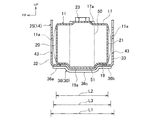
- 5 is a cross-sectional view taken along the line VV in FIG.
- FIG. 6 is a schematic diagram of an SCR system in which a reducing agent tank is used.
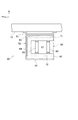
- FIG. 7 is a schematic view of a reducing agent tank mounting structure according to another embodiment.
- FR indicates the front of the vehicle
- UP indicates the upper side
- IN indicates the inner side in the vehicle width direction.
- the left-right direction means the left-right direction with the vehicle facing forward.
- a reducing agent tank (urea water tank) 11 is an SCR (Selective Catalytic Reduction) system 1 (see FIG. 6) that purifies NOx (nitrogen oxide) in engine exhaust gas using urea (urea water) as a reducing agent. Used to store urea water.
- An exhaust pipe 3 connected to a vehicle engine (for example, a diesel engine) 2 includes a reducing agent injection nozzle 4 that injects urea water as a reducing agent into the exhaust pipe 3 in order from the exhaust upstream side, and an exhaust pipe 3 interior.
- an SCR catalyst (selective reduction catalyst) 5 for reducing and purifying NOx (nitrogen oxide) in the exhaust gas with ammonia generated from the urea water injected into the exhaust gas.
- the urea water stored in the reducing agent tank 11 is supplied to the reducing agent supply pump 7 through the reducing agent supply pipe 6. A part of the urea water supplied to the reducing agent supply pump 7 is returned to the reducing agent tank 11 via the reducing agent return pipe 9.
- the reducing agent supply pump 7 is controlled by an ECU (engine control unit or electronic control unit) 8, and the exhaust temperature at the inlet of the SCR catalyst 5 detected by an exhaust temperature sensor (not shown) reaches the activation temperature of the SCR catalyst 5. When this occurs, an amount of urea water commensurate with the amount of NOx in the exhaust gas is supplied to the reducing agent injection nozzle 4.
- the reducing agent tank 11 includes, for example, a side surface on the outer side in the vehicle width direction of the vehicle body frame 12 of a cab over type truck in which the cab 22 is disposed generally above the engine 2 (this embodiment). Then, it is detachably fixed to the left side surface in the vehicle width direction via the bracket 14 and the two bands 15.
- the vehicle body frame 12 is, for example, a side member of a ladder frame.
- a plurality of other parts including a fuel tank 13 are also fixed to the vehicle body frame 12.
- the reducing agent tank 11 is made of a resin tank having a high degree of molding freedom, and includes an upper surface portion 17, a bottom surface portion (tank bottom surface portion, one bottom surface portion) 19, and a front surface portion (tank wall surface). Portion) 20, rear surface portion (tank wall surface portion) 21, inner surface portion 18, and outer surface portion 16, the outer shape is formed in a substantially rectangular parallelepiped.
- the upper surface part 17 is provided with a pipe connection part 23 to which pipes such as the reducing agent supply pipe 6 and the reducing agent return pipe 9 are connected.
- the bottom surface portion 19 faces the top surface portion 17 below the top surface portion 17.
- the front surface portion 20 and the rear surface portion 21 are opposed to each other while standing from both end edges in the front-rear direction (predetermined direction) of the bottom surface portion 19.
- the inner surface portion 18 and the outer surface portion 16 stand up from both end edges of the bottom surface portion 19 in the vehicle width direction and face each other.
- the outer surface portion 16 of the reducing agent tank 11 is formed with a convex portion 16a that protrudes outward in the vehicle width direction and extends in the vertical direction at the center portion in the front-rear direction of the outer surface portion 16.
- the upper surface portion 17 of the reducing agent tank 11 is formed with a convex portion 17a that protrudes upward at the center portion in the front-rear direction of the upper surface portion 17 and extends in the vehicle width direction.
- a pipe connection portion 23 is provided on the convex portion 17 a of the upper surface portion 17.
- a reducing agent supply port 24 is formed at a corner portion where the convex portion 17a of the upper surface portion 17 and the convex portion 16a of the outer surface portion 16 intersect, and the urea water can be easily supplied from the reducing agent supply port 24. .
- a convex portion 18 a that protrudes inward in the vehicle width direction at the center in the front-rear direction of the inner surface 18 and extends in the vertical direction is formed.
- a convex portion (tank side engaging portion) 19a (projecting downward in the center portion in the front-rear direction of the bottom surface portion 19 and extending in the vehicle width direction (direction intersecting with the predetermined direction) 5) is formed.
- the bracket 14 includes a mounting portion 26 that is attached to the outer surface in the vehicle width direction of the vehicle body frame 12, a pump support portion 27 that supports the reducing agent supply pump 7, and a tank that houses the reducing agent tank 11. It has the accommodating part 25 integrally.
- the bracket 14 is formed by bending a steel plate and is fixed to the vehicle body frame 12 to hold the reducing agent tank 11.
- the mounting portion 26 integrally includes front and rear fixing plate portions 26a and 26b and a main body portion 26c having a substantially U-shaped cross section between the front and rear fixing plate portions 26a and 26b. It is formed in a hat shape.
- the front and rear fixing plate portions 26 a and 26 b are fixed to the outer side surface of the body frame 12 in the vehicle width direction by bolts 28.
- the main body portion 26 c protrudes from the vehicle width direction outer side surface of the vehicle body frame 12 to the vehicle width direction outer side.
- the pump support portion 27 is disposed between the front and rear plate portions 27a and 27b and the front and rear plate portions 27a and 27b that extend outward from the main body portion 26c of the mounting portion 26 and face each other, and the front and rear plate portions 27a and 27b. 27a, 27b, and a lower plate portion 27c for connecting the two to each other.
- the lower plate portion 27c is fixed to the upper end portion of the main body portion 26c of the mounting portion 26 by a bolt 29 and protrudes outward in the vehicle width direction.
- the reducing agent supply pump 7 is fixed on the upper surface of the lower plate portion 27 c, and the front and rear plate portions 27 a and 27 b stand up and down before and after the reducing agent supply pump 7.
- the tank accommodating portion 25 includes a bottom plate portion (bracket bottom surface portion, the other bottom surface portion) 30 for supporting the bottom surface portion 19 of the reducing agent tank 11 from below, and the reducing agent tank 11. And a pair of front and rear plate portions (bracket wall surface portions) 32 and 33 that stand up and oppose each other from both front and rear edges of the bottom plate portion 30.
- the back plate portion 31 is below the pump support portion 27 and is fixed to the outer surface in the vehicle width direction of the front end portion of the main body portion 26 c of the attachment portion 26, and below the pump support portion 27, the attachment portion 26.
- the rear plate 31b fixed to the vehicle width direction outer side surface of the rear end portion of the main body portion 26c and the lower plate 31c extending in the front-rear direction below the front plate 31a and the rear plate 31b are substantially in a side view in the vehicle width direction. It is formed in a U shape.
- Each of the front plate 31a and the rear plate 31b is formed with three bolt holes 34 penetrating in the vehicle width direction, and a plurality of bolts 35 (FIG. 2 shows the upper end portion of the front plate 31a). Only the bolt 35 is shown), and the front plate 31a and the rear plate 31b are fixed to the mounting portion 26.
- the back plate portion 31 defines an inner side in the vehicle width direction of the tank housing space 42 that houses the reducing agent tank 11.
- the bottom plate portion 30 is integrally formed with the lower plate 31c of the back plate portion 31, and is bent from the lower end of the front end portion and the rear end portion of the lower plate 31c of the back plate portion 31 and extends to the outside in the vehicle width direction.
- 30b and a pair of support plates 36 that are spaced apart in the vehicle width direction and extend in the front-rear direction between the front and rear bottom plates 30a, 30b.
- the front and rear bottom plates 30a, 30b are spaced apart from each other in the front-rear direction, and the space between the front and rear bottom plates 30a, 30b is opened upward and outward in the vehicle width direction.
- the pair of support plates 36 includes front and rear fixed ends 36a and 36b fixed to the lower surfaces of the front and rear bottom plates 30a and 30b, and concave portions (bracket side engagement) recessed downward between the front and rear fixed ends 36a and 36b.
- Part) 36c, and front and rear fixed ends 36a, 36b and a recess 36c are integrally formed.
- the recesses 36 c of the pair of support plates 36 are formed in a shape that can be engaged with the protrusions 19 a of the bottom surface 19 of the reducing agent tank 11.
- both concave portions 36 c of the pair of support plates 36 constitute a concave portion extending in the vehicle width direction, and the bottom surface portion 19 of the reducing agent tank 11.
- a concave space extending in the vehicle width direction that can accommodate the convex portion 19a is defined.
- the length in the front-rear direction of the concave portion 36 c of the support plate 36 is slightly longer than the length in the front-rear direction of the convex portion 19 a of the bottom surface portion 19 of the reducing agent tank 11.
- the depth of the concave portion 36 c of the support plate 36 is such that the vertical distance from the upper surface of the concave portion 36 c of the support plate 36 to the upper surfaces of the bottom plates 30 a and 30 b before and after the bottom plate portion 30 is the convexity of the bottom surface portion 19 of the reducing agent tank 11.
- the distance is set to be substantially the same as the distance in the vertical direction from the lower surface of the portion 19a to the lower surface of the bottom surface portion 19 before and after the convex portion 19a.
- the length L1 in the front-rear direction of the bottom plate portion 30 is formed longer than the length L2 in the front-rear direction of the reducing agent tank 11 (see FIG. 5).
- the bottom plate part 30 defines a lower part of the tank housing space 42.
- the front and rear plate portions 32 and 33 are substantially triangular plate bodies having a plurality of (for example, three in this embodiment) holes 43 for weight reduction, and stand up from both front and rear edges of the bottom plate portion 30. Opposite each other.
- the front side plate portion 32 is bent from the front end edge of the bottom plate 30 a on the front side of the bottom plate portion 30 and extends upward
- the rear side plate portion 33 is bent from the rear end edge of the bottom plate 30 b on the rear side of the bottom plate portion 30. Extend upward. From the inner edge in the vehicle width direction of the front plate portion 32, the front plate 31a of the back plate portion 31 bends and extends rearward, and from the inner edge in the vehicle width direction of the rear plate portion 33 to the back plate portion.
- a rear plate 31b of 31 is bent forward and extends.
- the front and rear plate portions 32 and 33 each have an inclined edge 37 that continuously extends from the upper end of the back plate portion 31 to the outer end in the vehicle width direction of the bottom plate portion 30.
- the first band fixing portion 38 protrudes outward in the vehicle width direction from the lower end portion of the inclined edge 37 of the front and rear plate portions 32, 33.
- the second band fixing portion 39 protrudes upward from a substantially central portion in the vertical direction of the inclined edge 37 of the front and rear plate portions 32 and 33.
- Front and rear upper plates 40 and 41 are fixed to the rear surface of the front plate portion 32 and the front surface of the rear plate portion 33 by welding or the like.
- the front and rear top plates 40 and 41 are disposed at positions spaced upward from the front and rear bottom plates 30a and 30b of the bottom plate portion 30, and face the front and rear bottom plates 30a and 30b from above.
- the front and rear plate portions 32 and 33 partition the front and rear of the tank housing space 42, and the front and rear upper plates 40 and 41 partition the tank housing space 42. Note that the outside of the tank housing space 42 in the vehicle width direction is open.
- the two bands 15 are plate bodies extending in the front-rear direction, and the first band 44 and the second band fixed to the first band fixing portion 38 of the front and rear plate portions 32 and 33.
- the second band 45 is fixed to the fixing portion 39.
- the two bands 15 fix the reducing agent tank 11 to the tank housing portion 25 of the bracket 14.
- the first band 44 is formed by press-molding a metal plate extending in the front-rear direction, and front and rear fixed end portions 44a, 44b fixed to the first band fixing portion 38 of the front and rear plate portions 32, 33 by bolts 46, And a support recess 44c between the front and rear fixed ends 44a and 44b.
- the support recess 44c is bent so as to curve outward in the vehicle width direction and is recessed outward in the vehicle width direction, and a plate-like rubber 47 is fixed to the inner side surface in the vehicle width direction.
- the support recess 44 c of the first band 44 is formed in a shape that can be engaged with the convex portion 16 a of the outer surface portion 16 of the reducing agent tank 11 and can accommodate the convex portion 16 a of the outer surface portion 16 of the reducing agent tank 11.
- a recessed space extending in the direction is defined.
- the rubber 47 is disposed between the convex portion 16 a of the outer surface portion 16 of the reducing agent tank 11 and the support concave portion 44 c of the first band 44 in a state where the reducing agent tank 11 is fixed to the tank housing portion 25 by the first band 44. This prevents the first band 44 from directly touching the reducing agent tank 11 and damaging the reducing agent tank 11.
- the second band 45 is formed by press-molding a metal plate extending in the front-rear direction, and front and rear fixed end portions 45 a and 45 b fixed to the second band fixing portion 39 of the front and rear plate portions 32 and 33 by bolts 48. And a supporting recess 45c between the front and rear fixed ends 45a and 45b.
- the support recess 45c is bent so as to be bent upward and is recessed upward, and a plate-like rubber 49 is fixed to the inner side surface in the vehicle width direction.
- the support concave portion 45c of the second band 45 is formed in a shape that can be engaged with the convex portion 17a of the upper surface portion 17 of the reducing agent tank 11, and can accommodate the convex portion 17a of the upper surface portion 17 of the reducing agent tank 11.
- a recessed space extending in the direction is defined.
- the rubber 49 is located between the convex portion 17 a of the upper surface portion 17 of the reducing agent tank 11 and the support concave portion 45 c of the second band 45 in a state where the reducing agent tank 11 is fixed to the tank housing portion 25 by the second band 45. This prevents the second band 45 from directly touching the reducing agent tank 11 and damaging the reducing agent tank 11.
- the inner end portion in the vehicle width direction of the bottom surface portion 19 of the reducing agent tank 11 is placed on the upper surface of the outer end portion in the vehicle width direction of the bottom plate portion 30 of the tank housing portion 25 of the bracket 14. Then, the reducing agent tank 11 is slid and moved inward in the vehicle width direction.
- the reducing agent tank 11 is satisfactorily guided in the vehicle width direction by the engagement between the convex portion 19 a of the bottom surface portion 19 of the reducing agent tank 11 and the concave portion 36 c of the pair of support plates 36 of the bottom plate portion 30 of the bracket 14.
- the front and rear fixed ends 44 a and 44 b of the first band 44 are connected to the first band fixed portions 38 of the front and rear plate portions 32 and 33 of the bracket 14 with bolts 46.
- the front and rear fixed ends 45 a and 45 b of the second band 45 are fixed to the second band fixing portions 39 of the front and rear plate portions 32 and 33 of the bracket 14 with bolts 48.
- the reducing agent tank 11 is pressed against the back plate portion 31 of the bracket 14 by the first band 44 and pressed against the bottom plate portion 30 of the bracket 14 by the second band 45, and is firmly and easily fixed to the bracket 14. .
- the plate portion 32 on the front side of the bracket 14 is placed. Is disposed away from the front surface portion 20 of the reducing agent tank 11 and faces the front surface portion 20 of the reducing agent tank 11 from the front (outside).
- the plate portion 33 on the rear side of the bracket 14 is disposed rearwardly from the rear surface portion 21 of the reducing agent tank 11 and faces the rear surface portion 21 of the reducing agent tank 11 from the rear (outside).
- the gap between the front plate portion 32 of the bracket 14 and the front portion 20 of the reducing agent tank 11 and the gap between the rear plate portion 33 of the bracket 14 and the rear surface portion 21 of the reducing agent tank 11 are, for example, In the cold district or the like, the reducing agent tank 11 is set to a size that allows expansion of the reducing agent tank 11 when the reducing agent (urea water) inside the freezing agent tank 11 is frozen. That is, the length L1 in the front-rear direction of the bottom plate portion 30 of the bracket 14 is set to be longer than the length L3 in the front-rear direction of the expanded reducing agent tank 11a shown by a two-dot chain line in FIG.
- the positions of the plate portions 32 and 33 are arranged at positions where they are not pressed in the front-rear direction by the front surface portion 20 and the rear surface portion 21 of the expanded reducing agent tank 11a. Further, in the tank mounting state, the convex portion 19 a of the bottom surface portion 19 of the reducing agent tank 11 and the concave portion 36 c of the pair of support plates 36 of the bottom plate portion 30 of the bracket 14 are engaged, and the outer surface portion of the reducing agent tank 11. 16 is engaged with the support recess 44c of the first band 44 (see FIG. 2), and the protrusion 17a of the upper surface portion 17 of the reducing agent tank 11 and the support recess 45c of the second band 45 are engaged. (See FIG. 2).
- the front portion 20 and the rear portion 21 of the reducing agent tank 11 and the front and rear plate portions 32 and 33 of the bracket 14 are placed in the front-rear direction when the tank is placed.
- the gap between the front surface portion 20 and the rear surface portion 21 of the reducing agent tank 11 and the plate portions 32 and 33 before and after the bracket 14 is separated by the reducing agent inside the reducing agent tank 11 in a cold district or the like. Since the width of the reducing agent tank 11 is set so as to allow expansion when frozen, the bracket 14 can be prevented from being damaged even if the reducing agent tank 11 expands.
- the front portion 20 and the rear portion 21 of the reducing agent tank 11 and the front and rear plate portions 32 and 33 of the bracket 14 are separated in the front-rear direction to prevent the bracket 14 from being damaged when the reducing agent tank 11 is expanded. Therefore, for example, unlike the case where the rigidity of the bracket 14 is improved by increasing the thickness to prevent the bracket 14 from being damaged, the weight of the bracket 14 can be suppressed.
- the convex part 19a of the bottom face part 19 of the reducing agent tank 11 and the concave part 36c of the bottom plate part 30 of the bracket 14 engage with each other in the tank mounting state. Since the engagement between the convex portion 19a of the reducing agent tank 11 and the concave portion 36c of the bracket 14 restricts the movement of the reducing agent tank 11 in the front-rear direction with respect to the bracket 14, the front portion 20 and the rear portion 21 of the reducing agent tank 11 are used.
- front and rear plate portions 32 and 33 of the bracket 14 are spaced apart from each other in the front-rear direction, so that the front portion 20 and the rear surface portion 21 of the reducing agent tank 11 and the front and rear plate portions 32 and 33 of the bracket 14 Even if a gap is generated between them, the stability of the reducing agent tank 11 in the front-rear direction can be ensured.
- the convex portion 16 a of the outer surface portion 16 of the reducing agent tank 11 and the supporting concave portion 44 c of the first band 44 are engaged, and the convex portion 17 a of the upper surface portion 17 of the reducing agent tank 11 and the supporting concave portion 45 c of the second band 45 are engaged. And engage.
- the engagement between the convex portion 16 a of the reducing agent tank 11 and the support concave portion 44 c of the first band 44, and the engagement between the convex portion 17 a of the reducing agent tank 11 and the support concave portion 45 c of the second band 45 are performed with respect to the bracket 14. Since the movement of the reducing agent tank 11 in the front-rear direction is restricted, the stability of the reducing agent tank 11 in the front-rear direction can be reliably ensured.
- the stability of the reducing agent tank 11 can be ensured with a simple structure in which the bottom surface portion 19 of the reducing agent tank 11 and the bottom plate portion 30 of the bracket 14 are provided with irregularities.
- the weight of the bracket 14 can be prevented and the stability of the reducing agent tank 11 can be secured, and the bracket 14 can be prevented from being damaged when the reducing agent tank 11 is expanded.
- the reducing agent tank 11 is provided with the convex portions 16a, 17a, 18a, 19a on the outer surface portion 16, the upper surface portion 17, the inner surface portion 18, and the bottom surface portion 19, but the reducing agent tank 11 has a bottom surface portion.
- the convex portion 19 a may be provided only on 19.
- the convex portion 16 a of the reducing agent tank 11 and the support concave portion 44 c of the first band 44 are engaged to support the convex portion 17 a of the upper surface portion 17 of the reducing agent tank 11 and the second band 45.
- the recess 45c is engaged, the reducing agent tank 11 and the bands 44 and 45 may not be engaged.
- the convex portion 19a is provided on the bottom surface portion 19 (one bottom surface portion) of the reducing agent tank 11, and the concave portion 36c is provided on the bottom plate portion 30 (the other bottom surface portion) of the bracket 14.
- a concave portion may be provided on the bottom surface portion 19 (the other bottom surface portion) of the tank 11, and a convex portion may be provided on the bottom plate portion 30 (the one bottom surface portion) of the bracket 14.
- bracket 14 may not have the attachment portion 26 and the pump support portion 27. That is, the bracket 14 may have a tank housing portion 25, and the tank housing portion 25 may be directly fixed to the outer surface in the vehicle width direction of the vehicle body frame 12.
- the bottom part 19 of the reducing agent tank 11 is provided with a convex part (tank side engaging part) 19a
- the bottom plate part 30 of the bracket 14 is provided with a concave part (bracket side engaging part) 36c.
- the tank side engaging part of the reducing agent tank 11 and the bracket side engaging part of the bracket 14 are not limited to the above.
- a plate-like body may be protruded from the bottom surface portion 19 of the reducing agent tank 11, and a groove portion (bracket-side engaging portion) that supports the plate-like body so as to be slidable in the vehicle width direction. ) May be provided on the bottom plate 30 of the bracket 14.
- the bottom plate 30 of the bracket 14 is provided with a through hole (bracket side engaging portion) penetrating in the vertical direction, and a projecting portion (tank side engaging portion) that can be inserted and engaged with the through hole is used as a reducing agent tank.
- 11 may be provided on the bottom surface portion 19 of the eleventh.
- the engagement between the through hole (bracket side engaging portion) of the bottom plate portion 30 of the bracket 14 and the protruding portion (tank side engaging portion) of the bottom surface portion 19 of the reducing agent tank 11 is in the vertical direction with respect to the bracket 14. The movement of the reducing agent tank 11 in the crossing direction is restricted.
- the convex portion (tank side engaging portion) 19 a is provided on the bottom surface portion 19 of the reducing agent tank 11, and the concave portion 36 c is engaged with the convex portion 19 a and the bottom plate portion 30 of the bracket 14.
- the bottom surface portion 51 of the reducing agent tank 50 is bracketed without providing a convex portion (tank side engaging portion) on the bottom surface portion (tank bottom surface portion) 51. You may make it engage with the recessed part (bracket side engaging part) 36c of the 14 baseplate parts 30.
- the bottom surface portion 51 of the reducing agent tank 50 is shown at a position spaced upward from the recess 36 c of the bottom plate portion 30 of the bracket 14 for easy understanding on the drawing.
- the bottom surface portion 51 of the reducing agent tank 50 is placed in the recess 36 c of the bottom plate portion 30 of the bracket 14.
- the bracket 60 may integrally include a mounting portion 61 and a tank housing portion 62.
- the bracket 60 is different from the bracket 14 of the above embodiment in that the tank housing portion 62 is fixed to the mounting portion 61 so that the tank housing space 67 is opened rearward.
- the tank accommodating portion 62 is formed by a bottom plate portion (bracket bottom surface portion, the other bottom surface portion) 63, a front plate portion 64, and a pair of left and right side plate portions (bracket wall surface portions) 65 and 66, and is opened rearward.
- a tank accommodating space 67 is defined by a bottom plate portion 63, a front plate portion 64, and a pair of left and right side plate portions 65, 66.
- the pair of left and right side plate portions 65 and 66 stand up from both end edges of the bottom plate portion 63 in the vehicle width direction (predetermined direction) and face each other.
- the bottom plate portion 63 is formed with a recess (bracket side engaging portion) 68 extending in the front-rear direction (direction intersecting with the predetermined direction).
- the pair of left and right side plate portions 65 and 66 of the bracket 60 are connected to the pair of left and right wall surfaces (tank wall surface portion of the reducing agent tank 69).
- the convex part of the reducing agent tank 69 extends in the front-rear direction, and engages with the concave part 68 of the bottom plate part 63 of the bracket 60 in the tank-mounted state.
- the engagement between the concave portion 68 of the bracket 60 and the convex portion of the reducing agent tank 69 restricts the movement of the reducing agent tank 69 relative to the bracket 60 in the vehicle width direction.
- the reducing agent tank mounting structure of the present invention has the effect of preventing weight loss of the bracket, ensuring the stability of the reducing agent tank, and preventing damage to the bracket during expansion of the reducing agent tank. It is useful in that it provides a structure for stably attaching the reducing agent tank to the bracket while preventing deterioration of the fuel consumption of the vehicle due to an increase in weight.
- Reductant tank 12 Body frame 14, 60: Bracket 19: Bottom surface of the reductant tank (tank bottom surface, one bottom surface) 19a: convex part (tank side engaging part) of bottom face part of reducing agent tank 20: Front portion of tank of reducing agent (tank wall) 21: Rear part of reducing agent tank (tank wall) 30 and 63: bottom plate part of bracket (the bottom part of the bracket, the other bottom part) 32: Front plate of bracket (wall surface of bracket) 33: Rear plate of bracket (bracket wall) 36: A pair of support plates 36c in the bottom plate portion of the bracket: a recess in the pair of support plates (bracket side engaging portion) 51: Bottom part of reducing agent tank (bottom part of tank) 65, 66: A pair of left and right side plates of bracket (bracket wall surface) 68: Recessed portion of bracket bottom plate (bracket side engaging portion) 70, 71: A pair of left and right wall surfaces (tank wall surfaces) of the
Landscapes
- Engineering & Computer Science (AREA)
- Chemical & Material Sciences (AREA)
- Combustion & Propulsion (AREA)
- Mechanical Engineering (AREA)
- Transportation (AREA)
- Analytical Chemistry (AREA)
- Biomedical Technology (AREA)
- Environmental & Geological Engineering (AREA)
- Health & Medical Sciences (AREA)
- General Chemical & Material Sciences (AREA)
- Oil, Petroleum & Natural Gas (AREA)
- Chemical Kinetics & Catalysis (AREA)
- Life Sciences & Earth Sciences (AREA)
- Sustainable Development (AREA)
- Sustainable Energy (AREA)
- General Engineering & Computer Science (AREA)
- Exhaust Gas After Treatment (AREA)
- Exhaust Gas Treatment By Means Of Catalyst (AREA)
Abstract
還元剤タンク11の底面部19には、車幅方向に延びる凸部19aが形成される。ブラケット14の底板部30の1対の支持板36には、還元剤タンク11の凸部19aと係合可能に下方へ凹む凹部36cが形成される。タンク載置状態では、ブラケット14の前後の板部32,33は、還元剤タンク11の前後の面部20,21から前後方向に離間して配置され、ブラケット14の前後の板部32,33と、還元剤タンク11の前後の面部20,21との間の間隙は、還元剤タンク11の膨張を許容する広さに設定される。還元剤タンク11の凸部19aとブラケット14の凹部36cとの係合は、ブラケット14に対する還元剤タンク11の前後方向の移動を規制する。
Description
本発明は、車体フレームに対して還元剤タンクを取り付ける還元剤タンクの取付構造に関する。
特許文献1には、SCRシステムにおける尿素水タンクの大気開放構造の一例が記載されている。尿素水タンクは、樹脂製のタンクであり、略直方体形状に形成され、車体フレームに対してブラケットによって固定される。ブラケットは、車体フレームの外側面に取り付けられる取付部と、取付部の下端部から車両幅方向の外側に延出して尿素水タンクが載置される載置部と、取付部と載置部との間に位置し尿素水タンクの車両長さ方向の外側面の一部を覆う覆い部とから構成されている。なお、特許文献1の図3には、尿素水タンクの外側面とブラケットの覆い部とが近接または接触している状態が記載されている。
特許文献1に記載の尿素水(還元剤)タンクには、尿素水が貯留されており、尿素水は、尿素の水溶液であるので、寒冷地等の気温が低い場所などでは尿素水が凍結して、尿素水タンクが膨張する可能性がある。しかし、上記特許文献1に記載の尿素水タンクでは、尿素水タンクの外側面とブラケットの覆い部とが近接または接触しているので、尿素水タンク内の尿素水が凍結して尿素水タンクが膨張すると、ブラケットが破損してしまうおそれがある。上記問題を解決するために、尿素水タンクの外側面とブラケットの覆い部とを離間させると、尿素タンクの安定性が低下するおそれがある。また、ブラケットを厚肉化してブラケットの剛性を向上させると、ブラケットが重量化してしまうおそれがある。
そこで、本開示は、ブラケットの重量化を防止し、且つ還元剤タンクの安定性を確保して、還元剤タンクの膨張時のブラケットの破損を防止することが可能な還元剤タンクの取付構造を提供することを目的とする。
上記課題を解決するため、本開示の還元剤タンクの取付構造は、還元剤タンクとブラケットとを備える。還元剤タンクは、タンク底面部と、タンク底面部の所定方向の両端から起立する1対のタンク壁面部とを有する。ブラケットは、還元剤タンクのタンク底面部を下方から支持するブラケット底面部と、ブラケット底面部の上記所定方向の両端から起立して相対向し、タンク底面部がブラケット底面部によって支持されたタンク載置状態で1対のタンク壁面部に外側からそれぞれ対向する1対のブラケット壁面部とを有し、車体フレームに対して固定されて還元剤タンクを保持する。1対のブラケット壁面部と1対のタンク壁面部とは、タンク載置状態で還元剤タンクの膨張を許容するように上記所定方向に離間して配置される。ブラケット底面部にはタンク載置状態でタンク底面部と係合するブラケット側係合部が形成される。タンク底面部とブラケット底面部のブラケット側係合部との係合は、ブラケットに対する還元剤タンクの少なくとも上記所定方向に沿った移動を規制する。
上記構成では、1対のブラケット壁面部と1対のタンク壁面部とが、タンク載置状態で還元剤タンクの膨張を許容するように上記所定方向に離間して配置されるので、例えば、寒冷地等において還元剤タンクの内部の還元剤が凍結して還元剤タンクが膨張しても、ブラケットの破損を防止することができる。
また、1対のブラケット壁面部と1対のタンク壁面部とを上記所定方向に離間して配置することにより、還元剤タンクの膨張時のブラケットの破損を防止するので、例えば、厚肉化によりブラケットの剛性を向上させてブラケットの破損を防止する場合とは異なり、ブラケットの重量の増加を抑制することができる。
また、タンク載置状態でタンク底面部と係合するブラケット側係合部をブラケット底面部に形成し、タンク底面部とブラケット底面部のブラケット側係合部との係合が、ブラケットに対する還元剤タンクの少なくとも上記所定方向に沿った移動を規制するので、1対のブラケット壁面部と1対のタンク壁面部とを上記所定方向に離間して配置しても、還元剤タンクの安定性を確保することができる。
また、上記タンク底面部は、タンク載置状態でブラケット底面部のブラケット側係合部と係合するタンク側係合部を有してもよく、タンク底面部のタンク側係合部及びブラケット底面部のブラケット側係合部のうち、一方の底面部の係合部は、他方の底面部側へ突出した状態で上記所定方向と交叉する方向に延びる凸部であり、他方の底面部の係合部は、一方の底面部側から凹んだ状態で上記所定方向と交叉する方向に延びる凹部であってもよい。
上記構成では、上記所定方向と交叉する方向に延びる凹部と凸部とが係合するので、ブラケットに対する還元剤タンクの上記所定方向に沿った移動を確実に規制することができる。
また、タンク底面部及びブラケット底面部に相互に係合可能な凹凸を設けるという簡易な構造で還元剤タンクの安定性を確保することができる。
本開示に係る還元剤タンクの取付構造によれば、ブラケットの重量化を防止し、且つ還元剤タンクの安定性を確保して、還元剤タンクの膨張時のブラケットの破損を防止することができる。
以下、本開示に係る還元剤タンクの取付構造の一実施形態について、図面に基づいて説明する。なお、各図において、FRは車両の前方を、UPは上方を、INは車幅方向内側をそれぞれ示す。また、以下の説明において、左右方向は車両前方を向いた状態での左右方向を意味する。
還元剤タンク(尿素水タンク)11は、尿素(尿素水)を還元剤としてエンジンの排気ガス中のNOx(窒素酸化物)を浄化するSCR(Selective Catalytic Reduction)システム1(図6参照)において、尿素水を貯留するために用いられる。車両のエンジン(例えば、ディーゼルエンジン)2に接続された排気管3には、排気上流側から順に、還元剤たる尿素水を排気管3内に噴射する還元剤噴射ノズル4と、排気管3内に噴射された尿素水から生成されるアンモニアで排気ガス中のNOx(窒素酸化物)を還元浄化するSCR触媒(選択還元触媒)5とが配設される。還元剤タンク11に貯留された尿素水は、還元剤供給配管6を介して還元剤供給ポンプ7に供給される。また、還元剤供給ポンプ7に供給された尿素水の一部は、還元剤戻り配管9を介して還元剤タンク11に戻される。還元剤供給ポンプ7は、ECU(エンジン制御ユニット又は電子制御ユニット)8により制御され、排気温度センサ(図示省略)によって検出されるSCR触媒5の入口の排気温度がSCR触媒5の活性温度に達したとき、排気ガス中のNOxの量に見合った量の尿素水を還元剤噴射ノズル4に供給する。
図1及び図2に示すように、還元剤タンク11は、例えば、キャブ22が概ねエンジン2の上方に配置されるキャブオーバー型のトラックの車体フレーム12の車幅方向外側の側面(本実施形態では、車幅方向左側の側面)に対し、ブラケット14と2つのバンド15とを介して脱着可能に固定される。車体フレーム12は、例えば、ラダーフレームのサイドメンバである。また、車体フレーム12には、還元剤タンク11の他に、燃料タンク13を含む複数の他の部品も固定される。
図2及び図3に示すように、還元剤タンク11は、成形自由度の高い樹脂製タンクからなり、上面部17と底面部(タンク底面部、一方の底面部)19と前面部(タンク壁面部)20と後面部(タンク壁面部)21と内面部18と外面部16とによって外形を略直方体に形成されている。上面部17には、還元剤供給配管6及び還元剤戻り配管9等の配管が接続される配管接続部23が設けられる。底面部19は、上面部17の下方で上面部17に対向する。前面部20及び後面部21は、底面部19の前後方向(所定方向)の両端縁から起立して相対向する。内面部18及び外面部16は、底面部19の車幅方向の両端縁から起立して相対向する。
還元剤タンク11の外面部16には、外面部16の前後方向の中央部で車幅方向外側に突出して上下方向に延びる凸部16aが形成される。還元剤タンク11の上面部17には、上面部17の前後方向の中央部で上方に突出して車幅方向に延びる凸部17aが形成される。上面部17の凸部17aには、配管接続部23が設けられる。上面部17の凸部17aと外面部16の凸部16aとが交わる角部には、還元剤補給口24が形成され、還元剤補給口24から容易に尿素水を補給できるようになっている。還元剤タンク11の内面部18には、内面部18の前後方向の中央部で車幅方向内側に突出して上下方向に延びる凸部18aが形成される。還元剤タンク11の底面部19には、底面部19の前後方向の中央部で下方に突出して車幅方向(上記所定方向と交叉する方向)に延びる凸部(タンク側係合部)19a(図5参照)が形成される。
図2に示すように、ブラケット14は、車体フレーム12の車幅方向外側面に取付けられる取付部26と、還元剤供給ポンプ7を支持するポンプ支持部27と、還元剤タンク11を収容するタンク収容部25とを一体的に有する。ブラケット14は、鋼鈑を屈曲して形成され、車体フレーム12に固定されて還元剤タンク11を保持する。
取付部26は、前後の固定板部26a,26bと、前後の固定板部26a,26bの間の断面略コ字状の本体部26cとを一体的に有し、鋼鈑を屈曲して断面ハット状に形成される。前後の固定板部26a,26bは、車体フレーム12の車幅方向外側面にボルト28によって固定される。取付部26の前後の固定板部26a,26bが車体フレーム12に固定された状態で、本体部26cは、車体フレーム12の車幅方向外側面から車幅方向外側へ突出している。
ポンプ支持部27は、取付部26の本体部26cから車幅方向外側へ延びて相対向する前後の板部27a,27bと、前後の板部27a,27bの間に配置されて前後の板部27a,27b同士を連結する下板部27cとを有し、取付部26の本体部26cの上端部にボルト29によって固定されて車幅方向外側へ突出する。下板部27cの上面には、還元剤供給ポンプ7が固定され、還元剤供給ポンプ7の前後で前後の板部27a,27bが起立する。
図2及び図4に示すように、タンク収容部25は、還元剤タンク11の底面部19を下方から支持するための底板部(ブラケット底面部、他方の底面部)30と、還元剤タンク11の内面部18を支持するための背板部31と、底板部30の前後の両端縁から起立して相対向する前後1対の板部(ブラケット壁面部)32,33とを備える。
背板部31は、ポンプ支持部27よりも下方で取付部26の本体部26cの前端部の車幅方向外側面に固定される前板31aと、ポンプ支持部27よりも下方で取付部26の本体部26cの後端部の車幅方向外側面に固定される後板31bと、前板31a及び後板31bの下方で前後方向に延びる下板31cとによって、車幅方向側面視で略U字状に形成される。前板31a及び後板31bの各々には、車幅方向に貫通する3つのボルト孔34が形成され、ボルト孔34を挿通する複数のボルト35(図2には、前板31aの上端部のボルト35のみが示されている)によって前板31a及び後板31bが取付部26に固定される。背板部31は、還元剤タンク11を収容するタンク収容空間42の車幅方向内側を区画する。
底板部30は、背板部31の下板31cと一体形成されて背板部31の下板31cの前端部及び後端部の下端から曲折して車幅方向外側へ延びる前後の底板30a,30bと、前後の底板30a,30bの間で、車幅方向に離間して配置されて前後方向に延びる1対の支持板36とによって構成される。前後の底板30a,30bは、前後に離間して配置され、前後の底板30a,30bの間の空間は、上方及び車幅方向外側へ開放されている。1対の支持板36は、前後の底板30a,30bの下面に固定される前後の固定端部36a,36bと、前後の固定端部36a,36bの間で下方へ凹む凹部(ブラケット側係合部)36cとをそれぞれ有し、前後の固定端部36a,36bと凹部36cとが一体形成される。1対の支持板36の凹部36cは、還元剤タンク11の底面部19の凸部19aと係合可能な形状に形成される。1対の支持板36が前後の底板30a,30bに固定された状態で、1対の支持板36の両凹部36cは、車幅方向に延びる凹部を構成し、還元剤タンク11の底面部19の凸部19aを収容可能な車幅方向に延びる凹部空間を区画する。支持板36の凹部36cの前後方向の長さは、還元剤タンク11の底面部19の凸部19aの前後方向の長さよりも僅かに長く形成される。支持板36の凹部36cの深さは、支持板36の凹部36cの上面から底板部30の前後の底板30a,30bの上面までの上下方向の距離が、還元剤タンク11の底面部19の凸部19aの下面から凸部19aの前後の底面部19の下面までの上下方向の距離と略同じ長さになるように設定される。底板部30の前後方向の長さL1は、還元剤タンク11の前後方向の長さL2よりも長く形成される(図5参照)。底板部30は、タンク収容空間42の下方を区画する。
前後の板部32,33は、軽量化のための複数(例えば、本実施形態では3つ)の孔43を有する略三角形状の板体であり、底板部30の前後の両端縁から起立して相対向する。前側の板部32は、底板部30の前側の底板30aの前端縁から曲折して上方へ延び、後側の板部33は、底板部30の後側の底板30bの後端縁から曲折して上方へ延びる。前側の板部32の車幅方向内端縁からは、背板部31の前板31aが後方へ曲折して延び、後側の板部33の車幅方向内端縁からは、背板部31の後板31bが前方へ曲折して延びる。前後の板部32,33は、背板部31の上端から底板部30の車幅方向外端まで連続して延びる傾斜端縁37をそれぞれ有する。前後の板部32,33の傾斜端縁37の下端部からは、第1バンド固定部38が車幅方向外側へそれぞれ突出する。また、前後の板部32,33の傾斜端縁37の上下方向の略中央部からは、第2バンド固定部39が上方へそれぞれ突出する。前側の板部32の後面及び後側の板部33の前面には、前後の上板40,41が溶接等によって固定される。前後の上板40,41は、底板部30の前後の底板30a,30bから上方へ離間した位置に配置されて、前後の底板30a,30bに上方から対向する。前後の板部32,33は、タンク収容空間42の前方及び後方を区画し、前後の上板40,41は、タンク収容空間42の上方を区画する。なお、タンク収容空間42の車幅方向外側は開放されている。
図2に示すように、2つのバンド15は、前後方向に延びる板体であって、前後の板部32,33の第1バンド固定部38に固定される第1バンド44、及び第2バンド固定部39に固定される第2バンド45である。2つのバンド15は、ブラケット14のタンク収容部25に対して還元剤タンク11を固定する。
第1バンド44は、前後方向に延びる金属板をプレス成形して形成され、前後の板部32,33の第1バンド固定部38にボルト46によって固定される前後の固定端部44a,44bと、前後の固定端部44a,44bの間の支持凹部44cとを一体的に有する。支持凹部44cは、車幅方向外側へ湾曲するように屈曲形成されて車幅方向外側へ凹み、その車幅方向内側面には板状のラバー47が固定される。第1バンド44の支持凹部44cは、還元剤タンク11の外面部16の凸部16aと係合可能な形状に形成され、還元剤タンク11の外面部16の凸部16aを収容可能な上下方向に延びる凹部空間を区画する。ラバー47は、タンク収容部25に対して還元剤タンク11を第1バンド44によって固定した状態で、還元剤タンク11の外面部16の凸部16aと第1バンド44の支持凹部44cとの間に介在し、第1バンド44が還元剤タンク11に直接触れて還元剤タンク11を傷つけてしまうことを防止する。
第2バンド45は、前後方向に延びる金属板をプレス成形して形成され、前後の板部32,33の第2バンド固定部39にボルト48によって固定される前後の固定端部45a,45bと、前後の固定端部45a,45bの間の支持凹部45cとを一体的に有する。支持凹部45cは、上方へ湾曲するように屈曲形成されて上方へ凹み、その車幅方向内側面には板状のラバー49が固定される。第2バンド45の支持凹部45cは、還元剤タンク11の上面部17の凸部17aと係合可能な形状に形成され、還元剤タンク11の上面部17の凸部17aを収容可能な車幅方向に延びる凹部空間を区画する。ラバー49は、タンク収容部25に対して還元剤タンク11を第2バンド45によって固定した状態で、還元剤タンク11の上面部17の凸部17aと第2バンド45の支持凹部45cとの間に介在し、第2バンド45が還元剤タンク11に直接触れて還元剤タンク11を傷つけてしまうことを防止する。
還元剤タンク11をブラケット14に取付ける場合、還元剤タンク11の底面部19の車幅方向内端部をブラケット14のタンク収容部25の底板部30の車幅方向外端部の上面に載置し、そのまま車幅方向内側へ還元剤タンク11をスライド移動させる。還元剤タンク11は、還元剤タンク11の底面部19の凸部19aとブラケット14の底板部30の1対の支持板36の凹部36cとの係合により、車幅方向内側に良好に案内される。還元剤タンク11の内面部18がブラケット14の背板部31に当接すると、還元剤タンク11の車幅方向内側への移動が規制され、還元剤タンク11がタンク収容空間42に収容される。還元剤タンク11がタンク収容空間42に収容された状態で、第1バンド44の前後の固定端部44a,44bをブラケット14の前後の板部32,33の第1バンド固定部38にボルト46によって固定し、第2バンド45の前後の固定端部45a,45bをブラケット14の前後の板部32,33の第2バンド固定部39にボルト48によって固定する。還元剤タンク11は、第1バンド44によってブラケット14の背板部31に押しつけられ、第2バンド45によってブラケット14の底板部30に押しつけられて、強固に、かつ簡単にブラケット14に固定される。
図5に示すように、還元剤タンク11をタンク収容部25の底板部30に載置して、還元剤タンク11をブラケット14に取付けたタンク載置状態では、ブラケット14の前側の板部32は、還元剤タンク11の前面部20から前方へ離間して配置され、還元剤タンク11の前面部20に前方(外側)から対向する。ブラケット14の後側の板部33は、還元剤タンク11の後面部21から後方へ離間して配置され、還元剤タンク11の後面部21に後方(外側)から対向する。ブラケット14の前側の板部32と還元剤タンク11の前面部20との間の間隙、及びブラケット14の後側の板部33と還元剤タンク11の後面部21との間の間隙は、例えば、寒冷地等において還元剤タンク11の内部の還元剤(尿素水)が凍結した際の還元剤タンク11の膨張を許容する広さに設定される。すなわち、ブラケット14の底板部30の前後方向の長さL1は、図5中の2点鎖線で示す膨張した還元剤タンク11aの前後方向の長さL3よりも長く設定され、ブラケット14の前後の板部32,33の位置は、膨張した還元剤タンク11aの前面部20及び後面部21に前後方向に押圧されない位置に配置される。また、タンク載置状態では、還元剤タンク11の底面部19の凸部19aとブラケット14の底板部30の1対の支持板36の凹部36cとが係合し、還元剤タンク11の外面部16の凸部16aと第1バンド44の支持凹部44cとが係合し(図2参照)、還元剤タンク11の上面部17の凸部17aと第2バンド45の支持凹部45cとが係合する(図2参照)。この還元剤タンク11の凸部19aとブラケット14の凹部36cとの係合、還元剤タンク11の凸部16aと第1バンド44の支持凹部44cとの係合、及び還元剤タンク11の凸部17aと第2バンド45の支持凹部45cとの係合は、ブラケット14に対する還元剤タンク11の前後方向の移動を規制する。
上記のように構成された還元剤タンク11の取付構造では、タンク載置状態で還元剤タンク11の前面部20及び後面部21と、ブラケット14の前後の板部32,33とが前後方向に離間しており、還元剤タンク11の前面部20及び後面部21と、ブラケット14の前後の板部32,33との間の間隙は、寒冷地等において還元剤タンク11の内部の還元剤が凍結した際の還元剤タンク11の膨張を許容する広さに設定されているので、還元剤タンク11が膨張しても、ブラケット14の破損を防止することができる。
また、還元剤タンク11の前面部20及び後面部21と、ブラケット14の前後の板部32,33とを前後方向に離間させることにより、還元剤タンク11の膨張時のブラケット14の破損を防止するので、例えば、厚肉化によりブラケット14の剛性を向上させてブラケット14の破損を防止する場合とは異なり、ブラケット14の重量化を抑制することができる。
また、タンク載置状態で還元剤タンク11の底面部19の凸部19aとブラケット14の底板部30の凹部36cとが係合する。この還元剤タンク11の凸部19aとブラケット14の凹部36cとの係合は、ブラケット14に対する還元剤タンク11の前後方向の移動を規制するので、還元剤タンク11の前面部20及び後面部21と、ブラケット14の前後の板部32,33とを前後方向に離間して配置することにより、還元剤タンク11の前面部20及び後面部21と、ブラケット14の前後の板部32,33との間に間隙が生じても、還元剤タンク11の前後方向の安定性を確保することができる。
また、還元剤タンク11の外面部16の凸部16aと第1バンド44の支持凹部44cとが係合し、還元剤タンク11の上面部17の凸部17aと第2バンド45の支持凹部45cとが係合する。この還元剤タンク11の凸部16aと第1バンド44の支持凹部44cとの係合、及び還元剤タンク11の凸部17aと第2バンド45の支持凹部45cとの係合は、ブラケット14に対する還元剤タンク11の前後方向の移動を規制するので、還元剤タンク11の前後方向の安定性を確実に確保することができる。
また、還元剤タンク11の底面部19の車幅方向に延びる凸部19aとブラケット14の底板部30の車幅方向に延びる凹部36cとが係合するので、ブラケット14に対する還元剤タンク11の前後方向の移動を確実に規制することができる。
また、還元剤タンク11の底面部19及びブラケット14の底板部30に凹凸を設けるという簡易な構造で還元剤タンク11の安定性を確保することができる。
従って、本実施形態によれば、ブラケット14の重量化を防止し、且つ還元剤タンク11の安定性を確保して、還元剤タンク11の膨張時のブラケット14の破損を防止することができる。
なお、本実施形態では、還元剤タンク11の外面部16、上面部17、内面部18、及び底面部19に凸部16a,17a,18a,19aを設けたが、還元剤タンク11に底面部19のみに凸部19aを設けてもよい。
また、本実施形態では、還元剤タンク11の凸部16aと第1バンド44の支持凹部44cとを係合させて、還元剤タンク11の上面部17の凸部17aと第2バンド45の支持凹部45cとを係合させたが、還元剤タンク11と両バンド44,45とを係合させなくてもよい。
また、本実施形態では、還元剤タンク11の底面部19(一方の底面部)に凸部19aを設け、ブラケット14の底板部30(他方の底面部)に凹部36cを設けたが、還元剤タンク11の底面部19(他方の底面部)に凹部を設け、ブラケット14の底板部30(一方の底面部)に凸部を設けてもよい。
また、ブラケット14は、取付部26とポンプ支持部27とを有さなくてもよい。すなわち、ブラケット14は、タンク収容部25を有し、タンク収容部25が車体フレーム12の車幅方向外側面に直接固定されてもよい。
また、本実施形態では、還元剤タンク11の底面部19に凸部(タンク側係合部)19aを設け、ブラケット14の底板部30に凹部(ブラケット側係合部)36cを設けたが、還元剤タンク11のタンク側係合部及びブラケット14のブラケット側係合部は、上記に限定されるものではない。例えば、還元剤タンク11の底面部19に板状体(タンク側係合部)を突出させてもよく、該板状体を車幅方向にスライド移動自在に支持する溝部(ブラケット側係合部)をブラケット14の底板部30に設けてもよい。或いは、ブラケット14の底板部30に上下方向に貫通する貫通孔(ブラケット側係合部)を設け、該貫通孔に挿通して係合可能な突出部(タンク側係合部)を還元剤タンク11の底面部19に設けてもよい。この場合、ブラケット14の底板部30の貫通孔(ブラケット側係合部)と、還元剤タンク11の底面部19の突出部(タンク側係合部)との係合は、ブラケット14に対する上下方向と交叉する方向への還元剤タンク11の移動を規制する。
また、本実施形態では、還元剤タンク11の底面部19に凸部(タンク側係合部)19aを設け、該凸部19aとブラケット14の底板部30に凹部36cとを係合させたが、図5中の2点鎖線で示す還元剤タンク50ように、底面部(タンク底面部)51に凸部(タンク側係合部)を設けることなく、還元剤タンク50の底面部51をブラケット14の底板部30の凹部(ブラケット側係合部)36cに係合させてもよい。なお、図5では、図面上で分かり易くするために、還元剤タンク50の底面部51をブラケット14の底板部30の凹部36cから上方に離間した位置に記載しているが、実際には、還元剤タンク50の底面部51は、ブラケット14の底板部30の凹部36cに載置される。
以上、本開示に係る還元剤タンクの取付構造について、上記実施形態に基づいて説明を行ったが、本発明は上記実施形態の内容に限定されるものではなく、当然に本発明を逸脱しない範囲で適宜変更が可能である。すなわち、この実施形態に基づいて当業者等によりなされる他の実施形態、実施例および運用技術等は全て本発明の範疇に含まれることは勿論である。
例えば、図7に示すように、ブラケット60は、取付部61とタンク収容部62とを一体的に有してもよい。ブラケット60は、タンク収容空間67が後方へ開放されるようにタンク収容部62を取付部61に固定した点が上記実施形態のブラケット14とは異なる。タンク収容部62は、底板部(ブラケット底面部、他方の底面部)63と、前板部64と、左右1対の側板部(ブラケット壁面部)65,66とによって形成され、後方へ開放されるタンク収容空間67が底板部63と前板部64と左右1対の側板部65,66とによって区画される。左右1対の側板部65,66は、底板部63の車幅方向(所定方向)の両端縁から起立して相対向する。底板部63には、前後方向(上記所定方向と交叉する方向)に延びる凹部(ブラケット側係合部)68が形成される。還元剤タンク69をブラケット60の底板部63に載置したタンク載置状態で、ブラケット60の左右1対の側板部65,66は、還元剤タンク69の左右1対の壁面部(タンク壁面部)70,71から車幅方向に離間した位置に配置されて、左右1対の壁面部70,71に車幅方向の外側から対向する。ブラケット60の左右1対の側板部65,66と還元剤タンク69の左右1対の壁面部70,71との間の間隙は、還元剤タンク69の膨張を許容する。還元剤タンク69のタンク底面部(一方の底面部、図示省略)には、ブラケット60の底板部63の凹部68に係合する凸部(タンク側係合部、図示省略)が形成される。還元剤タンク69の凸部は、前後方向に延び、タンク載置状態でブラケット60の底板部63の凹部68と係合する。ブラケット60の凹部68と還元剤タンク69の凸部との係合は、ブラケット60に対する還元剤タンク69の車幅方向の移動を規制する。
本出願は、2015年06月12日付で出願された日本国特許出願(特願2015-118781)に基づくものであり、その内容はここに参照として取り込まれる。
本発明の還元剤タンクの取付構造は、ブラケットの重量化を防止し、且つ還元剤タンクの安定性を確保して、還元剤タンクの膨張時のブラケットの破損を防止することができるという効果を有し、重量増加による車両の燃費悪化を防止しつつ、還元剤タンクを安定してブラケットに取り付ける構造を提供するという点において有用である。
11,50,69:還元剤タンク
12:車体フレーム
14,60:ブラケット
19:還元剤タンクの底面部(タンク底面部、一方の底面部)
19a:還元剤タンクの底面部の凸部(タンク側係合部)
20:還元剤タンクの前面部(タンク壁面部)
21:還元剤タンクの後面部(タンク壁面部)
30,63:ブラケットの底板部(ブラケット底面部、他方の底面部)
32:ブラケットの前板部(ブラケット壁面部)
33:ブラケットの後板部(ブラケット壁面部)
36:ブラケットの底板部の1対の支持板
36c:1対の支持板の凹部(ブラケット側係合部)
51:還元剤タンクの底面部(タンク底面部)
65,66:ブラケットの左右1対の側板部(ブラケット壁面部)
68:ブラケットの底板部の凹部(ブラケット側係合部)
70,71:還元剤タンクの左右1対の壁面部(タンク壁面部)
12:車体フレーム
14,60:ブラケット
19:還元剤タンクの底面部(タンク底面部、一方の底面部)
19a:還元剤タンクの底面部の凸部(タンク側係合部)
20:還元剤タンクの前面部(タンク壁面部)
21:還元剤タンクの後面部(タンク壁面部)
30,63:ブラケットの底板部(ブラケット底面部、他方の底面部)
32:ブラケットの前板部(ブラケット壁面部)
33:ブラケットの後板部(ブラケット壁面部)
36:ブラケットの底板部の1対の支持板
36c:1対の支持板の凹部(ブラケット側係合部)
51:還元剤タンクの底面部(タンク底面部)
65,66:ブラケットの左右1対の側板部(ブラケット壁面部)
68:ブラケットの底板部の凹部(ブラケット側係合部)
70,71:還元剤タンクの左右1対の壁面部(タンク壁面部)
Claims (2)
- タンク底面部と、前記タンク底面部の所定方向の両端から起立する1対のタンク壁面部とを有する還元剤タンクと、
前記還元剤タンクの前記タンク底面部を下方から支持するブラケット底面部と、前記ブラケット底面部の前記所定方向の両端から起立して相対向し、前記タンク底面部が前記ブラケット底面部によって支持されたタンク載置状態で前記1対のタンク壁面部に外側からそれぞれ対向する1対のブラケット壁面部とを有し、車体フレームに対して固定されて前記還元剤タンクを保持するブラケットと、を備え、
前記1対のブラケット壁面部と前記1対のタンク壁面部とは、前記タンク載置状態で前記還元剤タンクの膨張を許容するように前記所定方向に離間して配置され、
前記ブラケット底面部には前記タンク載置状態で前記タンク底面部と係合するブラケット側係合部が形成され、
前記タンク底面部と前記ブラケット底面部の前記ブラケット側係合部との係合は、前記ブラケットに対する前記還元剤タンクの少なくとも前記所定方向に沿った移動を規制する
ことを特徴とする還元剤タンクの取付構造。 - 請求項1に記載の還元剤タンクの取付構造であって、
前記タンク底面部は、前記タンク載置状態で前記ブラケット底面部の前記ブラケット側係合部と係合するタンク側係合部を有し、
前記タンク底面部の前記タンク側係合部及び前記ブラケット底面部の前記ブラケット側係合部のうち、一方の底面部の係合部は、他方の底面部側へ突出した状態で前記所定方向と交叉する方向に延びる凸部であり、前記他方の底面部の係合部は、前記一方の底面部側から凹んだ状態で前記所定方向と交叉する方向に延びる凹部である
ことを特徴とする還元剤タンクの取付構造。
Priority Applications (1)
| Application Number | Priority Date | Filing Date | Title |
|---|---|---|---|
| CN201680034228.XA CN107709717B (zh) | 2015-06-12 | 2016-06-09 | 还原剂罐的安装构造 |
Applications Claiming Priority (2)
| Application Number | Priority Date | Filing Date | Title |
|---|---|---|---|
| JP2015118781A JP6774169B2 (ja) | 2015-06-12 | 2015-06-12 | 還元剤タンクの取付構造 |
| JP2015-118781 | 2015-06-12 |
Publications (1)
| Publication Number | Publication Date |
|---|---|
| WO2016199837A1 true WO2016199837A1 (ja) | 2016-12-15 |
Family
ID=57503391
Family Applications (1)
| Application Number | Title | Priority Date | Filing Date |
|---|---|---|---|
| PCT/JP2016/067173 Ceased WO2016199837A1 (ja) | 2015-06-12 | 2016-06-09 | 還元剤タンクの取付構造 |
Country Status (3)
| Country | Link |
|---|---|
| JP (1) | JP6774169B2 (ja) |
| CN (1) | CN107709717B (ja) |
| WO (1) | WO2016199837A1 (ja) |
Families Citing this family (2)
| Publication number | Priority date | Publication date | Assignee | Title |
|---|---|---|---|---|
| JP6880888B2 (ja) * | 2017-03-23 | 2021-06-02 | いすゞ自動車株式会社 | サプライモジュール固定構造 |
| JP7322914B2 (ja) * | 2021-03-24 | 2023-08-08 | いすゞ自動車株式会社 | 車載機器取付装置 |
Citations (4)
| Publication number | Priority date | Publication date | Assignee | Title |
|---|---|---|---|---|
| US20090188923A1 (en) * | 2007-12-10 | 2009-07-30 | Fuel Systems, Inc. | Urea solution tank assembly |
| JP2013092109A (ja) * | 2011-10-26 | 2013-05-16 | Mitsubishi Fuso Truck & Bus Corp | 液体タンクとその取付構造 |
| JP2015025456A (ja) * | 2014-10-07 | 2015-02-05 | 株式会社小松製作所 | ホイールローダ |
| JP2015028318A (ja) * | 2013-07-30 | 2015-02-12 | 住友建機株式会社 | 建設機械 |
Family Cites Families (3)
| Publication number | Priority date | Publication date | Assignee | Title |
|---|---|---|---|---|
| JPH0173024U (ja) * | 1987-10-30 | 1989-05-17 | ||
| JP5372727B2 (ja) * | 2009-12-24 | 2013-12-18 | いすゞ自動車株式会社 | 還元剤タンクの固定構造 |
| JP5212441B2 (ja) * | 2010-09-03 | 2013-06-19 | コベルコ建機株式会社 | 作業機械の燃料タンク取付装置 |
-
2015
- 2015-06-12 JP JP2015118781A patent/JP6774169B2/ja active Active
-
2016
- 2016-06-09 WO PCT/JP2016/067173 patent/WO2016199837A1/ja not_active Ceased
- 2016-06-09 CN CN201680034228.XA patent/CN107709717B/zh active Active
Patent Citations (4)
| Publication number | Priority date | Publication date | Assignee | Title |
|---|---|---|---|---|
| US20090188923A1 (en) * | 2007-12-10 | 2009-07-30 | Fuel Systems, Inc. | Urea solution tank assembly |
| JP2013092109A (ja) * | 2011-10-26 | 2013-05-16 | Mitsubishi Fuso Truck & Bus Corp | 液体タンクとその取付構造 |
| JP2015028318A (ja) * | 2013-07-30 | 2015-02-12 | 住友建機株式会社 | 建設機械 |
| JP2015025456A (ja) * | 2014-10-07 | 2015-02-05 | 株式会社小松製作所 | ホイールローダ |
Also Published As
| Publication number | Publication date |
|---|---|
| JP2017002849A (ja) | 2017-01-05 |
| CN107709717A (zh) | 2018-02-16 |
| CN107709717B (zh) | 2020-09-15 |
| JP6774169B2 (ja) | 2020-10-21 |
Similar Documents
| Publication | Publication Date | Title |
|---|---|---|
| CN102596619B (zh) | 还原剂箱的固定构造 | |
| EP2857292B1 (en) | Vehicle body structure | |
| US20090140014A1 (en) | Canister mounting structure | |
| JP6774169B2 (ja) | 還元剤タンクの取付構造 | |
| JP2013092114A (ja) | 車両のタンク組付構造 | |
| KR101880551B1 (ko) | 펌프 프로텍터가 결합된 자동차용 요소수 탱크 | |
| JP6693117B2 (ja) | 尿素水タンクの配置構造 | |
| JP2009167931A (ja) | 尿素水タンク | |
| JP2009174418A (ja) | 尿素水タンク | |
| JP6597220B2 (ja) | 車体構造 | |
| JP6648514B2 (ja) | 尿素水タンクの配置構造 | |
| JP2016117338A (ja) | 還元剤タンクの取付構造 | |
| JP6805803B2 (ja) | 車体構造 | |
| JP2015121162A (ja) | 車両部品用保護板 | |
| JP6930201B2 (ja) | サプライポンプ | |
| JP6582917B2 (ja) | タンク配置構造 | |
| JP6760042B2 (ja) | タンク固定構造 | |
| JP6805804B2 (ja) | ブラケット | |
| JP6668882B2 (ja) | 添加剤容器 | |
| JP2015121163A (ja) | 液体タンク用ブラケット | |
| JP2018144597A (ja) | 車体構造 | |
| KR20090041982A (ko) | 차량의 요소탱크 장착구조 | |
| JP6848536B2 (ja) | 車体構造 | |
| JP6880888B2 (ja) | サプライモジュール固定構造 | |
| JP2016047699A (ja) | 車両の後部構造 |
Legal Events
| Date | Code | Title | Description |
|---|---|---|---|
| 121 | Ep: the epo has been informed by wipo that ep was designated in this application |
Ref document number: 16807543 Country of ref document: EP Kind code of ref document: A1 |
|
| NENP | Non-entry into the national phase |
Ref country code: DE |
|
| 122 | Ep: pct application non-entry in european phase |
Ref document number: 16807543 Country of ref document: EP Kind code of ref document: A1 |