WO2016199599A1 - Biopsy needle - Google Patents
Biopsy needle Download PDFInfo
- Publication number
- WO2016199599A1 WO2016199599A1 PCT/JP2016/065761 JP2016065761W WO2016199599A1 WO 2016199599 A1 WO2016199599 A1 WO 2016199599A1 JP 2016065761 W JP2016065761 W JP 2016065761W WO 2016199599 A1 WO2016199599 A1 WO 2016199599A1
- Authority
- WO
- WIPO (PCT)
- Prior art keywords
- needle
- tip
- biopsy
- notch
- inner needle
- Prior art date
Links
Images


Classifications
-
- A—HUMAN NECESSITIES
- A61—MEDICAL OR VETERINARY SCIENCE; HYGIENE
- A61B—DIAGNOSIS; SURGERY; IDENTIFICATION
- A61B10/00—Other methods or instruments for diagnosis, e.g. instruments for taking a cell sample, for biopsy, for vaccination diagnosis; Sex determination; Ovulation-period determination; Throat striking implements
- A61B10/02—Instruments for taking cell samples or for biopsy
- A61B10/0233—Pointed or sharp biopsy instruments
- A61B10/0266—Pointed or sharp biopsy instruments means for severing sample
- A61B10/0275—Pointed or sharp biopsy instruments means for severing sample with sample notch, e.g. on the side of inner stylet
-
- A—HUMAN NECESSITIES
- A61—MEDICAL OR VETERINARY SCIENCE; HYGIENE
- A61B—DIAGNOSIS; SURGERY; IDENTIFICATION
- A61B10/00—Other methods or instruments for diagnosis, e.g. instruments for taking a cell sample, for biopsy, for vaccination diagnosis; Sex determination; Ovulation-period determination; Throat striking implements
- A61B10/02—Instruments for taking cell samples or for biopsy
- A61B10/0233—Pointed or sharp biopsy instruments
- A61B10/0241—Pointed or sharp biopsy instruments for prostate
-
- A—HUMAN NECESSITIES
- A61—MEDICAL OR VETERINARY SCIENCE; HYGIENE
- A61B—DIAGNOSIS; SURGERY; IDENTIFICATION
- A61B17/00—Surgical instruments, devices or methods, e.g. tourniquets
- A61B17/34—Trocars; Puncturing needles
- A61B17/3403—Needle locating or guiding means
- A61B2017/3413—Needle locating or guiding means guided by ultrasound
-
- A—HUMAN NECESSITIES
- A61—MEDICAL OR VETERINARY SCIENCE; HYGIENE
- A61B—DIAGNOSIS; SURGERY; IDENTIFICATION
- A61B90/00—Instruments, implements or accessories specially adapted for surgery or diagnosis and not covered by any of the groups A61B1/00 - A61B50/00, e.g. for luxation treatment or for protecting wound edges
- A61B90/36—Image-producing devices or illumination devices not otherwise provided for
- A61B90/37—Surgical systems with images on a monitor during operation
- A61B2090/378—Surgical systems with images on a monitor during operation using ultrasound
- A61B2090/3782—Surgical systems with images on a monitor during operation using ultrasound transmitter or receiver in catheter or minimal invasive instrument
- A61B2090/3784—Surgical systems with images on a monitor during operation using ultrasound transmitter or receiver in catheter or minimal invasive instrument both receiver and transmitter being in the instrument or receiver being also transmitter
Definitions
- the present invention relates to a biopsy needle for collecting biological tissue.
- an ultrasonic tomographic image obtained by an ultrasonic endoscope is used as a guide, and an elongated biopsy needle is guided to the observation site via a channel for a treatment tool of the ultrasonic endoscope to form a lesion tissue.
- Biopsy is performed in which biological tissue is collected by puncture.
- an inner needle having a notch for tissue collection formed on the distal side surface is arranged inside a hollow outer needle, and the inner needle and the outer needle are moved forward or backward by a moving mechanism. It has been proposed (see, for example, Patent Document 1).
- the biopsy needle is punctured to the tissue at the biopsy site with the outer needle of the biopsy needle substantially covering the notch of the inner needle, and then the inner needle protrudes from the tip of the outer needle until the notch is exposed.
- the living tissue enters the notch, so that the outer needle is advanced and the living tissue that has entered the notch is cut off at the tip of the outer needle, and the notch is covered with the outer needle while the living tissue is secured inside the notch.
- the outer needle is retracted to expose the notch, and the biological tissue inside the notch is collected.
- biopsy for diagnosing prostate cancer is currently performed transrectally or transperineally, but in order to reduce the invasion to the patient, biopsy is performed transurethrally from inside the prostate.
- a way to do is desired. According to this method, as long as the capsule (outer membrane) of the prostate is not penetrated from the inside to the outside, the needle tip does not contact the nerve running outside the prostate, and the patient burden may be further reduced.
- the notch that can be sampled is about 5 mm proximal to the tip of the needle, so the notch can be brought close to the capsule boundary to collect tissue near the capsule boundary of the prostate. If it reaches, it may be possible to penetrate the capsule with the needle tip, and the possibility of the needle tip contacting the nerve could not be denied. For this reason, there has been a demand to be able to collect a living tissue in the vicinity of the capsule boundary from the prostate capsule with almost no needle tip of the biopsy needle outside the capsule.
- the present invention has been made in view of the above, and it is possible to reliably collect a tissue and reduce the length of a biopsy needle protruding from a region from which the tissue is collected during tissue collection.
- the purpose is to provide a meter reading.
- a biopsy needle includes a cylindrical outer needle having a first needle tip at one end in the longitudinal direction, and a second needle formed at the tip.
- a distal end portion having a tip and an inclined surface inclined toward the second needle tip, and a notch portion formed with a notch for collecting a biological tissue on the side surface closer to the proximal end than the inclined surface;
- a guide portion that communicates from the distal end portion to the notch portion, and a columnar inner needle that is inserted into the outer needle so as to be movable forward and backward in the longitudinal direction of the outer needle.
- the biopsy needle according to the present invention is characterized in that the guide part is a groove communicating from the tip part to the notch part.
- the biopsy needle according to the present invention is characterized in that the depth of the groove is shallower on the distal end side than on the connecting portion side with the notch portion.
- the biopsy needle according to the present invention is characterized in that the bottom of the groove is inclined from the tip portion toward the connecting portion.
- the biopsy needle according to the present invention is characterized in that the guide portion is a notch portion obtained by notching a portion from the tip portion to the notch portion in the longitudinal direction with respect to the inner needle.
- the biopsy needle according to the present invention is characterized in that the cut-out surface of the cut-out portion is inclined from the tip portion toward the connecting portion.
- the biopsy needle according to the present invention is characterized in that a rib is provided in the notch portion.
- the biopsy needle according to the present invention is characterized in that the upper part of the rib is cut out in the longitudinal direction.
- the biopsy needle according to the present invention is characterized in that the notch portion and the guide portion are located on the same side as the second needle tip in the short direction of the inner needle.
- the biopsy needle according to the present invention is characterized in that the notch portion and the guide portion are located on the opposite side to the second needle tip in the short direction of the inner needle.
- the outer needle has the first needle tip formed by obliquely cutting the tip, and the inclined surface of the inner needle and the tip of the outer needle are formed.
- the notch is characterized by being substantially parallel.
- the outer needle and the inner needle are independently slid in the longitudinal direction, and the distal direction of the outer needle is larger than the maximum slidable distance in the distal direction of the inner needle.
- a moving mechanism in which a maximum slidable distance is set larger, and the outer needle and the inner needle are moved by the moving mechanism, whereby the second needle tip is moved to the first needle.
- a transition is made between a first state located on the tip side of the tip and a second state where the first needle tip is located on the tip side of the second needle tip.
- the biopsy needle according to the present invention is characterized in that the inner needle is cylindrical.
- a cylindrical outer needle having a first needle tip at one end in the longitudinal direction, a second needle tip formed at the tip, and the second needle tip at the tip.
- a tip portion having an inclined surface that is inclined, a notch portion in which a notch for collecting a biological tissue is formed on a side surface closer to the base end than the inclined surface, and a guide portion that communicates from the tip portion to the notch portion
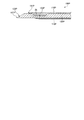
- FIG. 1 is a view for explaining a distal end portion of a biopsy needle according to the first embodiment.
- FIG. 2 is a cross-sectional view taken along line AA in FIG. 3 is a cross-sectional view taken along the line BB in FIG.
- FIG. 4 is a cross-sectional view when the distal end portion of the biopsy needle shown in FIG. 1 after biological tissue collection is cut along a plane passing through the central axis in the longitudinal direction of the biopsy needle and the center of the needle tip of the inner needle.
- FIG. 5 is a diagram for explaining a biopsy method using the biopsy needle shown in FIG. 1.
- FIG. 6 is a view for explaining a distal end portion of a biopsy needle according to a conventional technique.
- FIG. 7 is a cross-sectional view taken along line CC of FIG.
- FIG. 8 is a cross-sectional view of the distal end portion of the biopsy needle according to the prior art after collection of the biological tissue, cut along a plane passing through the central axis in the longitudinal direction of the biopsy needle and the center of the needle tip of the inner needle.
- FIG. 9 is a cross-sectional view of the distal end portion of the biopsy needle according to the related art after collection of the biological tissue, cut along a plane passing through the central axis in the longitudinal direction and the center of the needle tip of the inner needle.
- FIG. 10 is a cross-sectional view of the distal end portion of the biopsy needle according to the related art after collecting biological tissue, cut along a plane passing through the central axis in the longitudinal direction and the center of the needle tip of the inner needle.
- FIG. 11 is a cross-sectional view of the biopsy needle according to Embodiment 1 cut along a plane passing through the central axis in the longitudinal direction of the biopsy needle and the center of the needle tip of the inner needle.
- 12 is a diagram illustrating a first state and a second state of the biopsy needle shown in FIG.
- FIG. 13 is a diagram for explaining the protruding operation of the outer needle and the inner needle in the biopsy needle shown in FIG.
- FIG. 14A is a diagram illustrating a biopsy operation of the biopsy needle shown in FIG. FIG.
- FIG. 14B is a diagram illustrating a biopsy operation of the biopsy needle shown in FIG.
- FIG. 14C is a diagram illustrating a biopsy operation of the biopsy needle shown in FIG.
- FIG. 14D is a diagram illustrating a biopsy operation of the biopsy needle shown in FIG.
- FIG. 14E is a diagram illustrating a biopsy operation of the biopsy needle shown in FIG.
- FIG. 14F is a diagram for explaining a biopsy operation of the biopsy needle shown in FIG. 11.
- FIG. 15 is a cross-sectional view of the distal end portion of the biopsy needle according to Modification 1 of Embodiment 1 cut along a plane passing through the central axis in the longitudinal direction of the biopsy needle.
- 16 is a cross-sectional view taken along the line DD of FIG. FIG.
- FIG. 17 is a plan view of the distal end portion of the biopsy needle according to the second modification of the first embodiment.
- FIG. 18 is a cross-sectional view of the distal end portion of the biopsy needle according to Modification 2 of Embodiment 1 cut along a plane passing through the central axis in the longitudinal direction of the biopsy needle.
- FIG. 19 is a view for explaining the distal end portion of the biopsy needle according to the second embodiment.
- FIG. 20 is a cross-sectional view of the distal end portion of the biopsy needle according to the second embodiment after biological tissue collection, cut along a plane passing through the central axis in the longitudinal direction of the biopsy needle.
- FIG. 21 is a view for explaining the distal end portion of the biopsy needle according to the first modification of the second embodiment.
- FIG. 22 is a perspective view of the distal end portion of the inner needle shown in FIG. 23 is a cross-sectional view taken along the line EE of FIG.
- FIG. 24 is a plan view of the distal end portion of another biopsy needle according to the first modification of the second embodiment.
- FIG. 25 is a view for explaining a distal end portion of a biopsy needle according to a second modification of the second embodiment.
- FIG. 26 is a diagram illustrating another example of the distal end portion of the biopsy needle according to the second modification of the second embodiment.
- 27 is a cross-sectional view taken along line FF in FIG.
- FIG. 28 is a diagram illustrating another example of the distal end portion of the biopsy needle according to the second modification of the second embodiment.
- FIG. 29 is a cross-sectional view of the distal end portion of the biopsy needle according to Embodiment 3 cut along a plane passing through the central axis in the longitudinal direction of the biopsy needle.
- 30 is a cross-sectional view taken along the line GG of FIG.
- FIG. 31 is a cross-sectional view of the distal end portion of the biopsy needle according to Modification 1 of Embodiment 3 cut along a plane passing through the central axis in the longitudinal direction of the biopsy needle.
- 32 is a cross-sectional view taken along line HH in FIG.
- FIG. 33 is a side view of the distal end portion of the inner needle according to the second modification of the third embodiment.
- 34 is a perspective view of the distal end portion of the inner needle shown in FIG.
- FIG. 35 is a cross-sectional view taken along the line II of FIG.
- FIG. 36 is a cross-sectional view of the distal end portion of another inner needle according to Modification 2 of Embodiment 3 cut along a plane passing through the central axis in the longitudinal direction of the inner needle.
- FIG. 37 is a perspective view of the distal end portion of the inner needle shown in FIG. 38 is a cross-sectional view taken along line JJ of FIG.
- FIG. 39 is a view for explaining the distal end portion of the biopsy needle according to the fourth embodiment.
- FIG. 40 is a view on arrow L in FIG. 41 is a cross-sectional view taken along the line KK of FIG.
- FIG. 42 is a view for explaining a distal end portion of another biopsy needle according to the fourth embodiment.
- FIG. 43 is a view on arrow N in FIG. 44 is a cross-sectional view taken along line MM in FIG.
- FIG. 45 is a view for explaining a tip portion of another biopsy needle according to the fourth embodiment.
- FIG. 46 is a view on arrow P in FIG. 47 is a cross-sectional view taken along line OO in FIG.
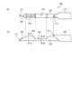
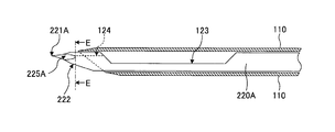
- FIG. 1 is a diagram for explaining a distal end portion of a biopsy needle according to the first embodiment.
- FIG. 1A is a plan view of the distal end portion of the biopsy needle according to the first embodiment
- FIG. 1B is a side view of the distal end portion of the biopsy needle according to the first embodiment.
- 2 is a cross-sectional view taken along line AA in FIG. 3 is a cross-sectional view taken along line BB in FIG.
- a biopsy needle 100 As shown in FIGS. 1 to 3, a biopsy needle 100 according to the first embodiment is inserted into a cylindrical outer needle 110 extending in the longitudinal direction and to be movable forward and backward in the longitudinal direction with respect to the outer needle 110. It has a solid cylindrical inner needle 120. As will be described later, the biopsy needle 100 accommodates the proximal ends of the outer needle 110 and the inner needle 120, and has an operation having a moving mechanism for sliding the outer needle 110 and the inner needle 120 independently in the longitudinal direction. A section (not shown).
- the outer needle 110 has a cylindrical shape with a sharp tip, and has a needle tip 111 (first needle tip) at the tip in the longitudinal direction.
- the outer needle 110 is formed of a biocompatible material, for example, a metal such as stainless steel, titanium, or aluminum, or a resin such as a fluororesin.
- the inner needle 120 is made of a material having biocompatibility, and an inclined surface inclined toward the needle tip 121 (second needle tip) formed at the tip and the needle tip 121 at the tip. And a notch part 123 in which a notch for collecting a living tissue is formed on the side surface closer to the base end side than the inclined surface 122.
- the needle tip 121 is located on a plane that passes through the central axis in the longitudinal direction of the inner needle 120. When viewed in the short direction, the tip of the inner needle 120 is cut so that a top is formed on the side opposite to the inclined surface 122, whereby the needle tip 121 is sharpened.
- the inclined surface 122 is formed by a processing method such as lancet, backcut, ceramine set, or flat sharpening.
- the notch 123 has a notch formed by notching the cylindrical portion along the longitudinal direction so that the notch surface is a flat surface at the base end side of the inclined surface 122 (see FIG. 3).
- the distal end surface and the base end surface are inclined from the bottom surface of the notch portion 123 toward the upper portion when viewed from the side surface.
- the inner needle 120 may have a prismatic shape as well as a cylindrical shape.
- the inner needle 120 has a groove 124 (guide portion) communicating from the tip portion to the notch portion 123.
- the inner needle 120 has a V-shaped groove 124 cut from the proximal end of the inclined surface 122 to the distal end surface of the notch portion 123.
- the depth of the groove 124 is set to be shallower than the depth of the notch portion 123.
- channel 124 are located in the reverse side to the formation part (top part) of the needle point 121 in a transversal direction.
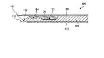
- FIG. 4 is a cross-sectional view when the distal end portion of the biopsy needle 100 after biological tissue collection is cut along a plane passing through the longitudinal center axis of the biopsy needle 100 and the center of the needle tip 121 of the inner needle 120.
- the living tissue When the living tissue is stabbed, the living tissue naturally enters the groove 124 on the distal end side by the energy at the time of injection of the inner needle 120, and further, the inner needle 120 is ejected, thereby passing through the groove 124 and being more than the groove 124.
- a living tissue is guided to the notch 123 on the proximal end side.
- the biopsy needle 100 can accommodate the biological tissue 2b in both the distal end side groove 124 and the proximal end side notch portion 123, and therefore, compared with a configuration in which the groove 124 is not formed. Many biological tissues can be collected.
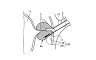
- FIG. 5 is a view for explaining a biopsy method using the biopsy needle 100 shown in FIG.
- an ultrasonic tomographic image obtained by an ultrasonic endoscope is used as a guide, and the insertion portion 10 of the ultrasonic endoscope reaches the biopsy target prostate 2 via the urethra 3 of the patient.
- the tip of the biopsy needle inserted into the treatment instrument channel of the insertion unit 10 is projected from the opening 11 at the tip of the insertion unit 10, and the outer needle 110 and the inner needle 120 are punctured into the prostate 2.
- the tip of the inner needle 120 is projected from the outer needle 110 until at least the groove 124 is exposed.
- the living tissue is sequentially guided to the notch portion 123 on the proximal end side with respect to the groove 124 via the groove 124.
- the outer needle 110 is advanced in the distal direction, and the biological tissue that has entered the groove 124 and the notch portion 123 is cut off at the distal end of the outer needle 110, while the biological tissue is secured in the groove 124 and the notch portion 123.
- the notch part 123 is covered with the outer needle 110.
- the biopsy needle is pulled out of the body through the treatment instrument channel, and then the biological tissue secured in the groove 124 and the notch 123 is collected.
- the bladder 4 is located in the back of the prostate 2.
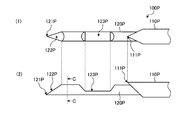
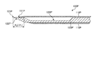
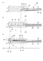
- FIG. 6 is a view for explaining a distal end portion of a biopsy needle according to a conventional technique.
- FIG. 6 (1) is a plan view of the distal end portion of the biopsy needle according to the prior art
- FIG. 6 (2) is a side view of the distal end portion of the biopsy needle according to the prior art.
- 7 is a cross-sectional view taken along the line CC of FIG.
- FIG. 8 to FIG. 10 are cross-sectional views when the distal end portion of a biopsy needle according to the prior art after biological tissue collection is cut along a plane passing through the central axis in the longitudinal direction of the biopsy needle and the center of the needle tip of the inner needle It is.
- the region between the base end of the inclined surface 122P and the notch portion 123P is a solid cylindrical shape only by forming 123P (see FIG. 7). For this reason, when using the biopsy needle 100P, in order to extract the living tissue 2b in the notch portion 123P as shown in FIG. 8, it is necessary to project the inner needle 120P from the outer needle 110P until the notch portion 123P is exposed. is there.
- the conventional biopsy needle 100P in order to reliably cover the tip of the notch portion 123P with the outer needle 110P so that the biological tissue does not escape from the notch portion 123P after collecting the biological tissue, as shown in FIG. from the needle tip 121P of 120P by increasing the length P 1 until the notch portion 123P to a length of about 5 ⁇ 6 mm it was required to have a certain margin. For this reason, with the conventional biopsy needle 100P, the needle tip 121P of the inner needle 120P has to be deeply punctured 5 to 6 mm deeper than the site where the tissue to be collected is located. Further, like the biopsy needle 100P ′ shown in FIG.
- the notch portion 123P ′ is extended in the distal direction to the vicinity of the proximal end of the inclined surface 122P ′, configuration in which shorten the length P 2 of the inner needle 120P' projecting from the site of harvesting target tissue to a length of about 2 ⁇ 3 mm have also been studied.
- the notch portion 123P ′ extends to the vicinity of the proximal end of the inclined surface 122P ′, so that the strength of the distal end portion of the inner needle 120P ′ decreases, and the inner needle 120P ′ is punctured into a hard tissue. In such a case, the inner needle 120P ′ may be bent.
- the position of the notch 123 remains the same, and only the groove 124 that communicates from the tip to the notch 123 is formed.
- the inner needle 120 is not bent even if the inner needle 120 is punctured into a hard tissue.
- the groove 124 communicating from the tip portion to the notch portion 123 is formed, and the biological tissue can be collected if at least the groove 124 reaches the region to be collected of the biological tissue. Therefore, according to the first embodiment, at the time of biopsy, the groove 124 on the distal end side with respect to the notch portion 123 only needs to reach the region to be collected of the living tissue, and the inner needle until the notch portion 123 on the proximal end side is reached. Since it is not necessary to project 120, the living tissue near the needle tip 121 can be collected in the groove 124 and the notch 123 while shortening the projecting length of the inner needle 120. Further, according to the first embodiment, since the living tissue 2b can be accommodated in both the distal end side groove 124 and the proximal end side notch portion 123, a large amount of living tissue can be collected.
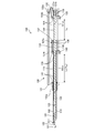
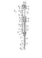
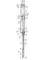
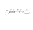
- FIG. 11 is a cross-sectional view of the biopsy needle 100 taken along a plane that passes through the central axis in the longitudinal direction of the biopsy needle 100 and the center of the needle tip of the inner needle 120.
- the biopsy needle 100 accommodates the proximal ends of the outer needle 110 and the inner needle 120 inside, and the outer needle 110 and the inner needle 120 are independently provided.
- It further includes an operation unit 130 having a moving mechanism that is slidably moved in the longitudinal direction.
- the operation unit 130 includes a trigger button 132, an inner needle charging coil spring 133, an inner needle slider 134, an inner needle knob 135, an inner needle stopper 136, an outer needle that function as a moving mechanism on the hollow columnar operation unit main body 131.
- the fixed hook release lever 137, the outer needle charging coil spring 138, the outer needle slider 139, the outer needle knob 140, and the outer needle stopper 141 are assembled.
- a luer base 131a is provided at the distal end, a spring assembly protrusion 131b is provided at the inner base end, and a trigger button hole 131c is provided above the spring assembly protrusion 131b.
- An inner needle knob groove 131d dug in the longitudinal direction is provided in the end bottom portion, and an outer needle knob groove 131e dug in the longitudinal direction is provided in the tip side bottom portion. From the luer base 131a, the distal ends of the outer needle 110 and the inner needle 120 protrude in the distal direction. A base end of a later-described inner needle charging coil spring 133 is assembled to the spring assembling convex portion 131b.
- an inner needle knob 135 to be described later can slide in the longitudinal direction.
- an outer needle knob 140 described later is slidable in the longitudinal direction.
- the trigger button 132 serves as a trigger for the forward operation of the inner needle 120, and both ends alternately move up and down around a fulcrum 132a connected to the inside of the operation unit main body 131.
- an inner needle fixing hook 132b that is caught in a recess of the inner needle slider 134 described later is provided.
- the inner needle charging coil spring 133 has a proximal end assembled to the proximal end portion of the spring assembly convex portion 131b, and a distal end assembled to the proximal end side surface of the inner needle slider 134, which will be described later, and expands after compression (charging). By doing so, the inner needle slider 134 is urged toward the distal direction.
- the inner needle slider 134 is connected to the proximal end of the inner needle 120, and is advanced in the distal direction by urging in the distal direction by the inner needle charging coil spring 133, and accordingly, the inner needle 120 is advanced in the distal direction.
- a concave portion into which the inner needle fixing hook 132b is fitted is formed on the upper surface of the inner needle slider 134.
- the inner needle knob 135 slides in the inner needle knob groove 131d so as to advance and retreat in the longitudinal direction.
- the upper surface of the inner needle knob 135 is connected to the lower surface of the inner needle slider 134.
- the lower part of the inner needle knob 135 protrudes from the inner needle knob groove 131d.
- the inner needle knob 135 advances in the inner needle knob groove 131d as the inner needle slider 134 advances. Further, the operator of the biopsy needle 100 moves the inner needle slider 134 and the inner needle 120 backward to the proximal end side by retracting the inner needle knob 135 toward the proximal end side along the inner needle knob groove 131d. Can do.
- the inner needle fixing hook 132b fits into the concave portion of the inner needle slider 134 and is fixed at a position where the inner needle 120 is disposed on the most proximal side. To do.
- the inner needle stopper 136 stops the forward movement of the inner needle slider 134, and accordingly, the forward movement of the inner needle 120 is also stopped.
- the outer needle fixing hook release lever 137 moves up and down with a fulcrum 137a connected to the inner needle stopper 136 as an axis.
- An outer needle fixing hook releasing lever 137 is provided with an outer needle fixing hook 137b that is caught in a recess of an outer needle slider 139 described later.
- the outer needle charging coil spring 138 has a proximal end assembled to the distal side surface of the inner needle stopper 136, and a distal end assembled to the proximal side surface of the outer needle slider 139 described later, and extends after compression (charging). As a result, the outer needle slider 139 is urged toward the distal end.
- the outer needle slider 139 is connected to the proximal end of the outer needle 110 and advances in the distal direction by urging the outer needle charging coil spring 138 in the distal direction, and accordingly, the outer needle 110 is advanced in the distal direction.
- On the upper surface of the outer needle slider 139 a recess into which the outer needle fixing hook 137b is fitted is formed.
- the outer needle knob 140 slides in the outer needle knob groove 131e so as to advance and retreat in the longitudinal direction.
- the top surface of the outer needle knob 140 is connected to the bottom surface of the outer needle slider 139.
- the lower part of the outer needle knob 140 protrudes from the outer needle knob groove 131e.
- the outer needle knob 140 advances in the outer needle knob groove 131e as the outer needle slider 139 advances.
- the operator of the biopsy needle 100 moves the outer needle slider 139 and the outer needle 110 backward to the proximal end side by retracting the outer needle knob 140 toward the proximal end side along the outer needle knob groove 131e. Can do.
- the outer needle fixing hook 137b fits into the concave portion of the outer needle slider 139, and is fixed at the position where the outer needle 110 is disposed on the most proximal side. To do.
- the outer needle stopper 141 is provided at the distal end portion of the operation portion main body 131, and stops the forward movement of the outer needle slider 139. Accordingly, the forward movement of the outer needle 110 is also stopped.
- the length L 1 in the longitudinal direction of the outer needle knob groove 131e that is, the stroke (maximum slidable distance) L 1 in the distal direction of the outer needle 110 is the length L in the longitudinal direction of the inner needle knob groove 131d. 2 , that is, larger than the stroke L 2 in the distal direction of the inner needle 120.
- Stroke L 2 is at least the grooves 124 is set so as to be exposed to a degree that can be tissue taken from the needle tip 111 of the outer needle 110.
- the groove 124 that communicates from the distal end portion to the notch portion 123 is formed, the first state and the second state are defined, and the first state and the second state are defined.
- the protruding length of the inner needle 120 from the collection target during biopsy is ensured so that the capsule 2a of the prostate 2 does not penetrate from the inside to the outside with the needle tip of the inner needle 120.
- the living tissue can be collected in the groove 124 and the notch portion 123.
- Biopsy needle 100 the longitudinal direction of the stroke L 1 of the outer needle 110, by setting larger than the longitudinal stroke L 2 in the inner needle 120 defines a first state and a second state. Next, the first state and the second state of the biopsy needle 100 will be described.
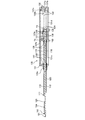
- FIG. 12 is a view for explaining the first state and the second state of the biopsy needle 100 shown in FIG. 1, and the distal end portion of the biopsy needle 100 is the central axis in the longitudinal direction of the biopsy needle 100 and the needle of the inner needle 120. It is sectional drawing cut
- (A) of FIG. 12 is a figure which shows a 1st state.
- the first state is a charge state in which the inner needle charging coil spring 133 and the outer needle charging coil spring 138 are both charged with energy for compression and expansion.
- the first state is a state in which energy for the outer needle 110 and the inner needle 120 to protrude is charged, and the outer needle 110 and the inner needle 120 are punctured into the biopsy site. It is.
- the needle point 121 of the inner needle 120 is located in the front end side rather than the needle point 111 of the outer needle 110.
- the needle tip 111 of the outer needle 110 is located closer to the distal end than the distal end of the groove 124 so that biological tissues other than the collection target do not enter the groove 124 while reaching the biological tissue to be collected. Ideally located.
- the second state is a state in which the inner needle 120 and the outer needle 110 have been slid to the biopsy site in the distal direction and the biopsy sampling has been completed.
- the needle tip 111 of the outer needle 110 is positioned on the distal side of the needle tip 121 of the inner needle 120. That is, the outer needle 110 is in a state of covering the entire groove 124 of the inner needle 120.
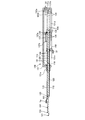
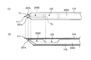
- FIG. 13 is a diagram for explaining the protruding operation of the outer needle 110 and the inner needle 120 in the biopsy needle 100 shown in FIG.
- FIG. 13 shows a case where the inner needle 120 and the outer needle 110 protrude in the x-axis direction.
- FIG. 13 is a cross-sectional view of the distal end portion of the biopsy needle 100 taken along a plane that passes through the central axis in the longitudinal direction of the biopsy needle 100 and the needle tip 121 of the inner needle 120.
- FIG. 13A shows a first state (charged state) in which the needle tip 121 of the inner needle 120 is positioned on the distal end side of the needle tip 111 of the outer needle 110, and the prostate 2 which is a biopsy site. The state before puncturing the site in the vicinity of the capsule 2a is shown.
- FIG. 13B shows a state in which only the inner needle 120 protrudes in the x-axis direction on the distal end side when the inner needle 120 is moved by the moving mechanism in order to collect tissue near the capsule 2a of the prostate 2.
- the inner needle 120 is different from the first state, the stroke L 2 minutes as described above, projecting in the x-axis direction.
- the needle tip 121 of the inner needle 120 from the position B 1 in the first state, the stroke L 2 minutes reaches the position B 2 in proximity to the capsules 2a which has moved to the x-axis direction.
- the groove 124 is sufficiently exposed, and the tissue of the prostate 2 enters the groove 124. Further, the tissue of the prostate 2 enters the notch 123 through the groove 124.
- FIG. 13C shows a second state in which the outer needle 110 protrudes and the biopsy operation is completed.
- Outer needle 110 is different from the first state, the stroke L 1 minute, projecting in the x-axis direction.
- the stroke L 1 is greater than the stroke L 2.
- the protrusion of the outer needle 110 secured the living tissue 2b inside the notch 123 and the groove 124 while cutting the tissue of the prostate 2 that entered the inside of the notch 123 and the groove 124 with the needle tip 111 of the outer needle 110.
- the notch 123 and the groove 124 can be completely covered with the outer needle 110.
- the biopsy needle 100 by setting larger than the longitudinal stroke L 2 in the inner needle 120 in the longitudinal direction of the stroke L 1 of the outer needle 110, the inner needle 120 needlepoint In a first state where 121 is in a charged state positioned on the distal end side of the needle tip 111 of the outer needle 110, the inner needle 120 and the outer needle 110 slide in the distal direction, and the needle tip 111 of the outer needle 110 becomes the inner needle. Transition between the second state located on the tip side of 120 needle tips 121 is possible, and the biological tissue 2b can be reliably collected in the notch 123 and the groove 124.
- the capsule 2a of the prostate 2 is removed from the inside by the needle tip 121 of the inner needle 120.
- the possibility of penetrating is greatly reduced.
- FIGS. 14A to 14F are diagrams for explaining the biopsy operation of the biopsy needle 100 shown in FIG. 11, and the biopsy needle 100 passes through the central axis in the longitudinal direction of the biopsy needle 100 and the center of the needle tip of the inner needle 120. It is sectional drawing cut
- FIG. 14A is a diagram illustrating a first state of the biopsy needle 100 described above. As shown in FIG. 14A, in the first state, the inner needle fixing hook 132b is caught in the recess of the inner needle slider 134, and the outer needle fixing hook 137b is caught in the recess of the outer needle slider 139.
- the coil spring 133 and the outer needle charging coil spring 138 are both compressed and charged with energy for expansion.
- the inner needle fixing hook 132b at the distal end rises around the fulcrum 132a and comes out of the recess of the inner needle slider 134, as shown in FIG. 14C.
- the compressed inner needle charging coil spring 133 extends in the distal direction and is urged by the extension of the inner needle charging coil spring 133, and the inner needle slider 134 slides in the distal direction as indicated by an arrow Yb. Accordingly, the inner needle 120 also slides in the distal direction as indicated by the arrow Yc.
- the inner needle slider 134 and the inner needle knob 135 are slid in the distal direction until the inner needle slider 134 and the inner needle knob 135 come into contact with the inner needle stopper 136 due to the bias of the inner needle charging coil spring 133. Then, the inner needle 120, the stroke L 2 minutes, projecting in the x-axis direction. Further, when the inner needle slider 134 pushes the outer needle fixing hook release lever 137 from the proximal end as shown by the arrow Yd by the bias of the inner needle charging coil spring 133, the outer needle fixing hook 137b at the distal end portion is centered on the fulcrum 137a.
- the operator of the biopsy needle 100 pulls out the biopsy needle 100 from the biopsy site in this state. Then, by moving the outer needle knob 140 to the proximal end of the outer needle knob groove 131e, the outer needle 110 is retracted (FIG. 14D), the notch portion 123 is exposed, and the living tissue inside the notch portion 123 is collected. To do. Thereafter, the biopsy needle 100 is shifted to the first state by moving the inner needle knob 135 to the proximal end of the inner needle knob groove 131d (FIG. 14A).
- the biopsy needle 100 is set such that the longitudinal stroke L 1 of the outer needle 110 is longer than the longitudinal stroke L 2 of the inner needle 120, and the outer needle 110 and the inner needle 120 are independent of each other.
- a moving mechanism for slidably moving in the longitudinal direction a transition between the first state and the second state is possible.
- FIG. 15 is a cross-sectional view of the distal end portion of the biopsy needle according to the first modification of the first embodiment cut along a plane passing through the central axis in the longitudinal direction of the biopsy needle.
- 16 is a cross-sectional view taken along the line DD of FIG.
- the groove 124A in which the distal end portion and the notch portion 123 communicate with each other may have a semi-circular cut shape.
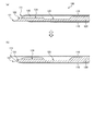
- FIG. 17 is a plan view of the distal end portion of the biopsy needle according to the second modification of the first embodiment.
- FIG. 18 is a cross-sectional view of the distal end portion of the biopsy needle according to the second modification of the first embodiment cut along a plane passing through the central axis in the longitudinal direction of the biopsy needle.
- 18 (1) is a diagram showing a first state of the biopsy needle according to the second modification of the first embodiment
- FIG. 18 (2) is a diagram illustrating a biopsy needle according to the second modification of the first embodiment. It is a figure which shows the 2nd state in a meter-reading.
- the outer needle 110 ⁇ / b> B may be vertically inverted with respect to the inner needle 120. That is, the notch at the tip of the outer needle 110B and the inclined surface 123 may be parallel.
- the outer needle 110B in the first state, does not necessarily cover the entire groove 124, and the needle tip 111P of the outer needle 110B If it reaches a part, it is enough. That is, if the region where the needle tip 111P of the outer needle 110B is projected in parallel to the short direction of the outer needle 110B and the inner needle 120 overlaps the inclined surface 122 of the inner needle 120, the biopsy needle to the living tissue There is no problem with puncture.
- the needle tip 111P of the outer needle 110B is more distal than the needle tip 121 of the inner needle 120. It is necessary to position and cover the tip of the groove 124 of the inner needle 120 with the outer needle 110 ⁇ / b> B so as to ensure the biological tissue within the notch 123 and the groove 124.
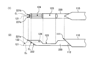
- FIG. 19 is a view for explaining the distal end portion of the biopsy needle according to the second embodiment.
- 19 (1) is a plan view of the distal end portion of the biopsy needle according to the second embodiment
- FIG. 19 (2) is a side view of the distal end portion of the biopsy needle according to the second embodiment. is there.
- FIG. 20 is a cross-sectional view of the distal end portion of the biopsy needle according to the second embodiment after biological tissue collection, cut along a plane passing through the central axis in the longitudinal direction of the biopsy needle.
- the biopsy needle according to the second embodiment has the inner needle 220 to cut away the tip portion D 1 of the needle 120A among shown in FIG. 15 .
- the inclined surface 222 is set so that the inclined surface 222 of the inner needle 220 and the inclined surface 112 of the outer needle 110 are substantially parallel.
- needle tip of the inner needle 220 is divided from the position C 1 two of the needle tip 221a, the 221b.
- the needle tip 111 of the outer needle 110 is slightly moved to the distal end side of the needle tip 221a of the inner needle 220.
- the needle tips 221 a and 221 b of the inner needle 220 can be accommodated in the outer needle 110 simply by projecting.
- the inner needle 220 because the groove 124 is formed to communicate with the needle tip 221a, from the position C 1 between 221b in the notch portion 123, can collect the biological tissue 2b at approximately the distal end of the inner needle 220, the biological It is also possible to collect a biological tissue in a state where the needle tips 221a and 221b of the inner needle 220 do not protrude from the tissue collection target region. Since the needle tip 111 of the outer needle 110 can be accommodated inside the outer needle 110 by slightly projecting the needle tip 111 slightly toward the distal end side of the needle tip 221a of the inner needle 220, the needle tip 111 of the outer needle 110 can also be accommodated. There is almost no protrusion from the collection target region of the biological tissue, and there is no possibility of damaging a portion outside the collection target region.
- the groove formed in the inner needle is not limited to the V-shaped groove 124 but may be a groove 124A (see FIG. 16) having a semicircular shape.
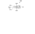
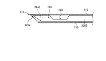
- FIG. 21 is a view for explaining the distal end portion of the biopsy needle according to the first modification of the second embodiment.
- the outer needle is shown cut in a plane passing through the central axis in the longitudinal direction of the outer needle.
- 22 is a perspective view of the distal end portion of the inner needle shown in FIG. 23 is a cross-sectional view taken along the line EE of FIG.
- the needle tip 221A of FIGS. 21 to 23 As shown in the inner needle 220A of FIGS. 21 to 23, as the needle tip 221A is formed at a position C 1, performs a D-cut machining two surfaces 225A, needle tip 221a of the needle 220 within shown in FIG. 19 , 221b is cut off.
- the groove 124 communicates directly with the notch portion 123 from the needle tip 221A (position C 1 )
- the living tissue 2b can be collected at the forefront of the inner needle 220A, and the inner needle 220A and the outer needle 110 can be connected.
- the needle tip of the inner needle 220A is not divided into two, the resistance at the time of puncture is reduced, the force of puncture with respect to the needle tip 221A is easily transmitted, and puncture can be performed with a lighter force.
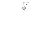
- FIG. 24 is a plan view of the tip portion of another biopsy needle according to the first modification of the second embodiment.
- a shape in which a D-cut process is performed on the surface 225B and the needle tip 221b portion of the inner needle 220 shown in FIG. 19 is cut off as in the inner needle 220B shown in FIG. Also in this shape, since the needle tip of the inner needle 220B is not divided into two, the resistance at the time of puncture is reduced, the force of puncture with respect to the needle tip 221a is easily transmitted, and the puncture can be performed with a lighter force.
- FIG. 25 is a view for explaining a distal end portion of a biopsy needle according to the second modification of the second embodiment.
- FIG. 25 (1) is a plan view of the distal end portion of the biopsy needle according to the second modification of the second embodiment
- FIG. 25 (2) is a raw view according to the second modification of the second embodiment. It is a side view of the front-end
- Figure groove 224C of the inner needle 220C of 25 the bottom of the groove 224C is, compared with the groove 124 of the needle 220 inner 19, the center C 2 of the connecting portion between the notch portion 123 from the position C 1 of the distal portion It is formed so as to incline toward.
- the groove 224C is formed such that the bottom becomes shallower toward the tip.
- the living tissue enters the groove 224C in a state where the needle tip side is narrower than the notch portion 123 side, so that it is easy to cut off at the distal end of the outer needle 110, and the grooves 224C and A living tissue can be collected in the notch portion 123.
- the living tissue can be collected at almost the tip of the inner needle 220C.
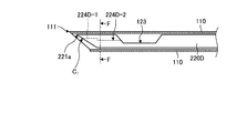
- FIG. 26 is a diagram illustrating another example of the distal end portion of the biopsy needle according to the second modification of the second embodiment.
- the outer needle is shown cut in a plane passing through the central axis in the longitudinal direction of the outer needle.
- 27 is a cross-sectional view taken along line FF in FIG.
- the groove 224D-1 on the distal end side is grooved so that the bottom is shallower than the groove 224D-2 on the connection part side with the notch portion 123.
- a step may be provided at the bottom.
- the living tissue enters the grooves 224D-1 and 224D-2 in a state where the needle tip side is narrower than the notch portion 123 side, so that it is easy to cut off the tip of the outer needle 110.
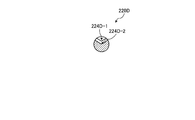
- FIG. 28 is a diagram showing another example of the distal end portion of the biopsy needle according to the second modification of the second embodiment.
- the outer needle is shown in a state of being cut by a plane passing through the central axis in the longitudinal direction of the outer needle.
- a projection 224E may be provided in the middle of the groove 124 as in an inner needle 220E shown in FIG.
- the protrusion 224E allows the living tissue that has entered the groove 124 to become thinner in the middle, so that the cutting at the tip of the outer needle 110 can be performed smoothly.
- the protrusion 224E is on the distal end side rather than the proximal end side of the groove 124.
- FIG. 29 is a cross-sectional view of the distal end portion of the biopsy needle according to Embodiment 3 cut along a plane passing through the central axis in the longitudinal direction of the biopsy needle.
- the tip shape of the inner needle before the formation of the notch is indicated by a broken line La.
- 30 is a cross-sectional view taken along the line GG of FIG.
- a portion from the proximal end of the inclined surface 122 of the distal end portion to the notch portion 123 is arranged in the longitudinal direction on the inner needle 320.
- a notch portion 324 (guide portion) that is notched is formed. Even when the notch 324 is formed, when the living tissue is punctured, the living tissue naturally enters the notch 324 by the energy when the inner needle 320 is ejected, and the inner needle 320 is ejected, so that the notch is cut. A living tissue is guided to the notch 123 via the notch 324.
- the notch 324 guides the entry of the living tissue into the notch 123 as long as the notch 324 reaches the region where the biological tissue is to be collected.
- the biological tissue to be collected can be accommodated in the notch portion 123.
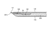
- FIG. 31 is a cross-sectional view of the tip portion of the biopsy needle according to Modification 1 of Embodiment 3 cut along a plane that passes through the central axis in the longitudinal direction of the biopsy needle.
- the tip shape of the inner needle before the formation of the notch is indicated by a broken line Lb.
- 32 is a cross-sectional view taken along line HH in FIG.
- the notch surface of the notch portion 324A is inclined from the base end 326 of the inclined surface 122, which is the tip portion, toward the connecting portion 327 with the notch portion 123. May be.
- the gap between the inner needle 320A and the outer needle 110 becomes narrower toward the tip, so that the tip of the outer needle 110 can be easily cut off.
- the living tissue can be reliably recovered inside the notch 324A and the notch 123.
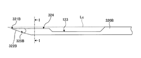
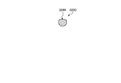
- FIG. 33 is a side view of the distal end portion of the inner needle according to the second modification of the third embodiment.
- the shape of the tip of the inner needle before the formation of the notch is indicated by a broken line Lc.
- 34 is a perspective view of the distal end portion of the inner needle shown in FIG. 35 is a cross-sectional view taken along the line II of FIG.
- the inner needle 320 shown in FIG. 29 has a configuration in which the notch portion 123 and the notch portion 324 are located on the side of the inclined surface 122 that is different from the needle tip 121 in the short direction, whereas FIG. In the inner needle 320B according to the second modification of the third embodiment shown in FIG. 35, the notch 123 and the notch 324 are located on the same side as the needle tip 321B at the tip of the inclined surface 322B in the short direction. In the case of this shape, since the notch 324 starts directly from the needle tip 321B, the biological tissue can be collected at the tip of the inner needle 320B, and the inner needle 320B and the outer needle 110 are almost completely separated from the collection target region of the biological tissue.
- the side surface of the needle tip 321B is D-cut from both sides with the surface 325B, and the needle tip 321B is sharpened so that the puncture force on the needle tip 321B can be easily transmitted. .
- FIG. 36 is a cross-sectional view of the distal end portion of another inner needle according to Modification 2 of Embodiment 3 cut along a plane passing through the central axis in the longitudinal direction of the inner needle.
- FIG. 37 is a perspective view of the distal end portion of the inner needle shown in FIG. 38 is a cross-sectional view taken along line JJ of FIG.
- the inner needle 320A shown in FIG. 31 has a configuration in which the notch portion 123 and the notch portion 324A are located on the side different from the needle tip 121 forming portion (top portion) at the tip of the inclined surface 122 in the short direction.
- the notch part 123 and the notch part 324A are located on the same side as the formation part of the needle tip 321C at the tip of the inclined surface 322C in the short direction. Also in this case, since the notch portion 324A communicates directly with the notch portion 123 from the needle tip 321C, the living tissue can be collected at the tip of the inner needle 320C, and the inner needle 320C and the outer needle 110 are removed from the collection target region of the living tissue. Almost no protrusion is required.
- the notch surface of the notch 324A is inclined from the needle tip 321C toward the proximal end, and therefore the tip of the inner needle 320C is not cut out, and the needle tip 321C is pointed. Since the shape can be maintained, the D-cut processing on the side surface of the tip is not necessary.
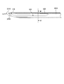
- FIG. 39 is a view for explaining the distal end portion of the biopsy needle according to the fourth embodiment.
- the outer needle is shown cut in a plane passing through the central axis in the longitudinal direction of the outer needle.
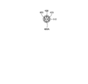
- FIG. 40 is a view on arrow L in FIG. 41 is a cross-sectional view taken along the line KK of FIG.
- a rib 428 is provided in the notch portion 423 to reinforce the strength of the inner needle.
- the inner needle 420 can easily transmit the puncture force to the needle tip 221A, and can puncture a harder tissue.
- the inner needle 420 has a notch 423 at the distal end as compared with the inner needle 220A of FIGS. It can also be stretched to the side.
- FIG. 42 is a view for explaining a tip portion of another biopsy needle according to the fourth embodiment.
- the outer needle is shown in a state of being cut by a plane passing through the central axis in the longitudinal direction of the outer needle.
- 43 is a view on arrow N in FIG. 44 is a cross-sectional view taken along line MM in FIG.
- a rib 428 is provided on the notch portion 423 to reinforce the strength of the inner needle, whereby the notch portion 423 is provided. May be further extended to the tip side.
- FIG. 45 is a diagram for explaining a tip portion of another biopsy needle according to the fourth embodiment.
- the outer needle is shown cut in a plane passing through the central axis in the longitudinal direction of the outer needle.
- FIG. 46 is a view on arrow P in FIG. 47 is a cross-sectional view taken along line OO in FIG.
- the notch 324 at the distal end of the inner needle 420A shown in FIGS. 42 to 44 is extended so that the upper portion of the rib 428C is also between the distal end and the proximal end of the rib 428C.
- a cutout portion 424C may be formed.
- the inner needle 420C having this configuration since the cutout portion 424C is formed, the amount of collected biological tissue can be increased, and the notch portion 423 partitioned by the rib 428C can be communicated with the cutout portion 424C.
- the collected biological tissue can be almost completely removed by taking out from either one of the notch portions 423, so that the operation of taking out the biological tissue from the biopsy needle can be performed only once.
- the case where the tissue of the prostate 2 is collected using the biopsy needle 100 has been described as an example.
- the tissue may be collected not only for the prostate 2 but also for any part.
- the case where the tip of the biopsy needle 100 reaches the biopsy site via the treatment instrument channel of the insertion unit 10 of the ultrasonic endoscope has been described as an example, but depending on the biopsy site, It is also possible to puncture the biopsy needle 100 from outside the body without going through the treatment instrument channel of the ultrasonic endoscope.
- the biopsy needle according to the present invention is useful for reliably collecting a tissue and shortening the length of a biopsy needle protruding from a tissue collection target site during tissue collection.
Landscapes
- Health & Medical Sciences (AREA)
- Life Sciences & Earth Sciences (AREA)
- Medical Informatics (AREA)
- Engineering & Computer Science (AREA)
- Biomedical Technology (AREA)
- Heart & Thoracic Surgery (AREA)
- Pathology (AREA)
- Molecular Biology (AREA)
- Surgery (AREA)
- Animal Behavior & Ethology (AREA)
- General Health & Medical Sciences (AREA)
- Public Health (AREA)
- Veterinary Medicine (AREA)
- Ultra Sonic Daignosis Equipment (AREA)
- Surgical Instruments (AREA)
Abstract
A biopsy needle (100) according to the present invention is equipped with a cylindrical outer needle (110) having a needle tip (111) on one end thereof in the lengthwise direction, and a column-shaped inner needle (120) which is to be inserted into the outer needle (110) so as to be capable of insertion thereinto and withdrawal therefrom in the lengthwise direction of the outer needle (110), and has: a tip end section having a needle tip (121) formed on the tip end thereof, and an angled surface (122) that angles toward the needle tip (121); a notched section (123) in which a notch for collecting biological tissue is formed in a lateral surface on the base end side relative to the angled surface (122); and a groove (124) that connects the tip end section and the notched section (123).
Description
本発明は、生体組織を採取するための生検針に関する。
The present invention relates to a biopsy needle for collecting biological tissue.
従来、病理確定診断等のために、超音波内視鏡による超音波断層像をガイドにし、超音波内視鏡の処置具用チャンネルを介して細長い生検針を観察部位まで誘導して病変組織に穿刺することによって生体組織を採取する生検が行なわれている。生検針として、中空の外針の内部に、先端側側面に組織採取用の切り欠き(ノッチ)が形成された内針を配置し、内針および外針を移動機構で前進或いは後退させる構成が提案されている(例えば、特許文献1参照)。生検では、生検針の外針が内針のノッチをほぼ覆った状態で生検部位の組織まで生検針を穿刺した後に、ノッチが露出するまで外針先端から内針を突出させる。これによってノッチ内部に生体組織が入り込むため、外針を前進させて、ノッチ内部に入り込んだ生体組織を外針先端で切り取りながら、ノッチ内部に生体組織を確保した状態でノッチを外針で覆う。この状態で生検針を生検部位から引き抜いた後に、外針を後退させることによってノッチを露出させ、ノッチ内部の生体組織を採取している。
Conventionally, for pathological diagnosis, etc., an ultrasonic tomographic image obtained by an ultrasonic endoscope is used as a guide, and an elongated biopsy needle is guided to the observation site via a channel for a treatment tool of the ultrasonic endoscope to form a lesion tissue. Biopsy is performed in which biological tissue is collected by puncture. As a biopsy needle, an inner needle having a notch for tissue collection formed on the distal side surface is arranged inside a hollow outer needle, and the inner needle and the outer needle are moved forward or backward by a moving mechanism. It has been proposed (see, for example, Patent Document 1). In a biopsy, the biopsy needle is punctured to the tissue at the biopsy site with the outer needle of the biopsy needle substantially covering the notch of the inner needle, and then the inner needle protrudes from the tip of the outer needle until the notch is exposed. As a result, the living tissue enters the notch, so that the outer needle is advanced and the living tissue that has entered the notch is cut off at the tip of the outer needle, and the notch is covered with the outer needle while the living tissue is secured inside the notch. In this state, after pulling out the biopsy needle from the biopsy site, the outer needle is retracted to expose the notch, and the biological tissue inside the notch is collected.
ところで、前立腺癌の診断のための生検は、現在、経直腸的或いは経会陰的に行われているが、患者への侵襲を低減するために、経尿道的に前立腺内部から生検を行う方法が望まれている。この方法によれば前立腺のカプセル(外側膜)を内側から外に貫かない限り、前立腺の外側を走行する神経に針先が接触することがなく、患者負担をより低減できる可能性がある。
By the way, biopsy for diagnosing prostate cancer is currently performed transrectally or transperineally, but in order to reduce the invasion to the patient, biopsy is performed transurethrally from inside the prostate. A way to do is desired. According to this method, as long as the capsule (outer membrane) of the prostate is not penetrated from the inside to the outside, the needle tip does not contact the nerve running outside the prostate, and the patient burden may be further reduced.
しかしながら、従来の生検針では、検体採取が可能なノッチが針先より5mm程度基端側の部分になってしまうため、前立腺のカプセル境界近くにある組織を採取するためにノッチをカプセル境界近くまで到達させると、針先でカプセルを貫いてしまう場合も考えられ、神経に針先が接触する可能性が否定できなかった。このため、前立腺のカプセルから、カプセル外部へ生検針の針先をほとんど外に出すことなく、カプセル境界近傍の生体組織を採取できるようにしたいという要求があった。
However, with a conventional biopsy needle, the notch that can be sampled is about 5 mm proximal to the tip of the needle, so the notch can be brought close to the capsule boundary to collect tissue near the capsule boundary of the prostate. If it reaches, it may be possible to penetrate the capsule with the needle tip, and the possibility of the needle tip contacting the nerve could not be denied. For this reason, there has been a demand to be able to collect a living tissue in the vicinity of the capsule boundary from the prostate capsule with almost no needle tip of the biopsy needle outside the capsule.
本発明は、上記に鑑みてなされたものであって、組織を確実に採取するとともに、組織採取の際に、組織の採取対象の部位から突出する生検針の長さを短くすることができる生検針を提供することを目的とする。
The present invention has been made in view of the above, and it is possible to reliably collect a tissue and reduce the length of a biopsy needle protruding from a region from which the tissue is collected during tissue collection. The purpose is to provide a meter reading.
上述した課題を解決し、目的を達成するために、本発明に係る生検針は、長手方向の一端に第1の針先を有する筒状の外針と、先端に形成された第2の針先と先端の前記第2の針先に向かって傾斜する傾斜面とを有する先端部と、前記傾斜面よりも基端側の側面に生体組織を採取するためのノッチが形成されたノッチ部と、前記先端部から前記ノッチ部まで連通するガイド部と、を有し、前記外針に対して該外針の長手方向に進退自在に挿通される柱状を成す内針と、を備えたことを特徴とする。
In order to solve the above-described problems and achieve the object, a biopsy needle according to the present invention includes a cylindrical outer needle having a first needle tip at one end in the longitudinal direction, and a second needle formed at the tip. A distal end portion having a tip and an inclined surface inclined toward the second needle tip, and a notch portion formed with a notch for collecting a biological tissue on the side surface closer to the proximal end than the inclined surface; A guide portion that communicates from the distal end portion to the notch portion, and a columnar inner needle that is inserted into the outer needle so as to be movable forward and backward in the longitudinal direction of the outer needle. Features.
また、本発明に係る生検針は、前記ガイド部は、前記先端部から前記ノッチ部まで連通する溝であることを特徴とする。
The biopsy needle according to the present invention is characterized in that the guide part is a groove communicating from the tip part to the notch part.
また、本発明に係る生検針は、前記溝の深さは、先端部側の方が、前記ノッチ部との連結部側よりも浅いことを特徴とする。
Further, the biopsy needle according to the present invention is characterized in that the depth of the groove is shallower on the distal end side than on the connecting portion side with the notch portion.
また、本発明に係る生検針は、前記溝の底は、前記先端部から前記連結部に向かって傾斜することを特徴とする。
Further, the biopsy needle according to the present invention is characterized in that the bottom of the groove is inclined from the tip portion toward the connecting portion.
また、本発明に係る生検針は、前記ガイド部は、前記内針に対し、前記先端部から前記ノッチ部までの部分を長手方向に切り欠いた切り欠き部であることを特徴とする。
Further, the biopsy needle according to the present invention is characterized in that the guide portion is a notch portion obtained by notching a portion from the tip portion to the notch portion in the longitudinal direction with respect to the inner needle.
また、本発明に係る生検針は、前記切り欠き部の切り欠き面は、前記先端部から前記連結部に向かって傾斜することを特徴とする。
Further, the biopsy needle according to the present invention is characterized in that the cut-out surface of the cut-out portion is inclined from the tip portion toward the connecting portion.
また、本発明に係る生検針は、前記ノッチ部には、リブが設けられていることを特徴とする。
The biopsy needle according to the present invention is characterized in that a rib is provided in the notch portion.
また、本発明に係る生検針は、前記リブの上部は、長手方向に切り欠かれていることを特徴とする。
The biopsy needle according to the present invention is characterized in that the upper part of the rib is cut out in the longitudinal direction.
また、本発明に係る生検針は、前記ノッチ部および前記ガイド部は、前記内針の短手方向において前記第2の針先と同じ側に位置することを特徴とする。
The biopsy needle according to the present invention is characterized in that the notch portion and the guide portion are located on the same side as the second needle tip in the short direction of the inner needle.
また、本発明に係る生検針は、前記ノッチ部および前記ガイド部は、前記内針の短手方向において前記第2の針先と逆側に位置することを特徴とする。
Further, the biopsy needle according to the present invention is characterized in that the notch portion and the guide portion are located on the opposite side to the second needle tip in the short direction of the inner needle.
また、本発明に係る生検針は、前記外針は、先端が斜めに切り欠かれることによって前記第1の針先が形成されており、前記内針の傾斜面と、前記外針の先端の切り欠きとは、略平行であることを特徴とする。
Further, in the biopsy needle according to the present invention, the outer needle has the first needle tip formed by obliquely cutting the tip, and the inclined surface of the inner needle and the tip of the outer needle are formed. The notch is characterized by being substantially parallel.
また、本発明に係る生検針は、前記外針および前記内針をそれぞれ独立して長手方向にスライドさせ、前記内針の先端方向へのスライド可能な最大距離よりも前記外針の先端方向へのスライド可能な最大距離の方が大きく設定される移動機構をさらに備え、前記外針および前記内針は、前記移動機構によって移動されることによって、前記第2の針先が前記第1の針先よりも先端側に位置する第1の状態と、前記第1の針先が前記第2の針先よりも先端側に位置する第2の状態との間を遷移することを特徴とする。
In the biopsy needle according to the present invention, the outer needle and the inner needle are independently slid in the longitudinal direction, and the distal direction of the outer needle is larger than the maximum slidable distance in the distal direction of the inner needle. A moving mechanism in which a maximum slidable distance is set larger, and the outer needle and the inner needle are moved by the moving mechanism, whereby the second needle tip is moved to the first needle. A transition is made between a first state located on the tip side of the tip and a second state where the first needle tip is located on the tip side of the second needle tip.
また、本発明に係る生検針は、前記内針は、円柱状であることを特徴とする。
The biopsy needle according to the present invention is characterized in that the inner needle is cylindrical.
本発明に係る生検針によれば、長手方向の一端に第1の針先を有する筒状の外針と先端に形成された第2の針先と先端の前記第2の針先に向かって傾斜する傾斜面とを有する先端部と、前記傾斜面よりも基端側の側面に生体組織を採取するためのノッチが形成されたノッチ部と、前記先端部から前記ノッチ部まで連通するガイド部と、を有し、前記外針に対して該外針の長手方向に進退自在に挿通される柱状を成す内針と、を備えることによって、ガイド部を介して組織を確実に採取するとともに、先端部までガイド部が連通するため、組織採取の際に組織の採取対象の部位から突出する生検針の長さを短くすることができる。
According to the biopsy needle of the present invention, a cylindrical outer needle having a first needle tip at one end in the longitudinal direction, a second needle tip formed at the tip, and the second needle tip at the tip. A tip portion having an inclined surface that is inclined, a notch portion in which a notch for collecting a biological tissue is formed on a side surface closer to the base end than the inclined surface, and a guide portion that communicates from the tip portion to the notch portion And having a columnar inner needle that is inserted into the outer needle so as to be movable forward and backward in the longitudinal direction of the outer needle, and reliably collecting tissue through the guide portion, Since the guide portion communicates with the distal end portion, the length of the biopsy needle that protrudes from the site of tissue collection can be shortened during tissue collection.
以下、本発明を実施するための形態を図面とともに詳細に説明する。なお、以下の実施の形態により本発明が限定されるものではない。また、以下の説明において参照する各図は、本発明の内容を理解でき得る程度に形状、大きさ、および位置関係を概略的に示してあるに過ぎない。すなわち、本発明は、各図で例示された形状、大きさおよび位置関係のみに限定されるものではない。また、以下の説明において、人間を含む動物の生体組織内に穿刺されて生体組織を採取する生検針を例示するが、この実施の形態によって本発明が限定されるものではない。また、同一の構成には同一の符号を付して説明する。
Hereinafter, embodiments for carrying out the present invention will be described in detail with reference to the drawings. In addition, this invention is not limited by the following embodiment. The drawings referred to in the following description only schematically show the shape, size, and positional relationship so that the contents of the present invention can be understood. That is, the present invention is not limited only to the shape, size, and positional relationship illustrated in each drawing. In the following description, a biopsy needle that is punctured into a living tissue of an animal including a human and collects the living tissue is illustrated, but the present invention is not limited to this embodiment. Further, the same components are described with the same reference numerals.
(実施の形態1)
図1は、本実施の形態1に係る生検針の先端部分を説明するための図である。図1の(1)は、本実施の形態1に係る生検針の先端部分の平面図であり、図1の(2)は、本実施の形態1に係る生検針の先端部分の側面図である。図2は、図1のA-A線断面図である。図3は、図1のB-B線断面図である。 (Embodiment 1)
FIG. 1 is a diagram for explaining a distal end portion of a biopsy needle according to the first embodiment. FIG. 1A is a plan view of the distal end portion of the biopsy needle according to the first embodiment, and FIG. 1B is a side view of the distal end portion of the biopsy needle according to the first embodiment. is there. 2 is a cross-sectional view taken along line AA in FIG. 3 is a cross-sectional view taken along line BB in FIG.
図1~3に示すように、本実施の形態1に係る生検針100は、長手方向に延設した筒状の外針110と、外針110に対して長手方向に進退自在に挿通される中実の円柱状の内針120とを有する。なお、生検針100は、後述するように、外針110および内針120の基端を内部に収納するとともに外針110および内針120をそれぞれ独立して長手方向にスライドさせる移動機構を有する操作部(不図示)をさらに備える。
As shown in FIGS. 1 to 3, a biopsy needle 100 according to the first embodiment is inserted into a cylindrical outer needle 110 extending in the longitudinal direction and to be movable forward and backward in the longitudinal direction with respect to the outer needle 110. It has a solid cylindrical inner needle 120. As will be described later, the biopsy needle 100 accommodates the proximal ends of the outer needle 110 and the inner needle 120, and has an operation having a moving mechanism for sliding the outer needle 110 and the inner needle 120 independently in the longitudinal direction. A section (not shown).
外針110は、先端が尖った筒状を成し、長手方向の先端に針先111(第1の針先)を有する。外針110は、生体適合性を有する材料、例えば、ステンレス、チタン、アルミなどの金属やフッ素樹脂などの樹脂によって形成される。
The outer needle 110 has a cylindrical shape with a sharp tip, and has a needle tip 111 (first needle tip) at the tip in the longitudinal direction. The outer needle 110 is formed of a biocompatible material, for example, a metal such as stainless steel, titanium, or aluminum, or a resin such as a fluororesin.
内針120は、外針110と同様に、生体適合性を有する材料によって形成され、先端に形成された針先121(第2の針先)と先端の針先121に向かって傾斜する傾斜面122とを有する先端部と、傾斜面122よりも基端側の側面に生体組織を採取するためのノッチが形成されたノッチ部123と、を備える。針先121は、内針120の長手方向の中心軸を通る平面上に位置する。短手方向で見た場合に、傾斜面122と逆側に頂部ができるように内針120先端がカット加工されることによって、針先121を尖形化する。傾斜面122は、ランセット、バックカット、セラミンセット、平研ぎ等の加工方法によって形成される。ノッチ部123は、傾斜面122よりも基端側の部分において、切り欠き面が平面となるように(図3参照)、円柱部を長手方向に沿って切り欠くことによってノッチが形成される。ノッチ部123において、先端面および基端面は、側面から見た場合、ノッチ部123の底面から上部に向かって傾斜する。なお、内針120は、円柱状だけではなく角柱状でもよい。
Similarly to the outer needle 110, the inner needle 120 is made of a material having biocompatibility, and an inclined surface inclined toward the needle tip 121 (second needle tip) formed at the tip and the needle tip 121 at the tip. And a notch part 123 in which a notch for collecting a living tissue is formed on the side surface closer to the base end side than the inclined surface 122. The needle tip 121 is located on a plane that passes through the central axis in the longitudinal direction of the inner needle 120. When viewed in the short direction, the tip of the inner needle 120 is cut so that a top is formed on the side opposite to the inclined surface 122, whereby the needle tip 121 is sharpened. The inclined surface 122 is formed by a processing method such as lancet, backcut, ceramine set, or flat sharpening. The notch 123 has a notch formed by notching the cylindrical portion along the longitudinal direction so that the notch surface is a flat surface at the base end side of the inclined surface 122 (see FIG. 3). In the notch portion 123, the distal end surface and the base end surface are inclined from the bottom surface of the notch portion 123 toward the upper portion when viewed from the side surface. The inner needle 120 may have a prismatic shape as well as a cylindrical shape.
さらに、内針120は、先端部からノッチ部123まで連通する溝124(ガイド部)を有する。図1および図2に示すように、内針120には、傾斜面122の基端からノッチ部123の先端面まで、V字型に溝124が切られている。図1~図3の例では、溝124の深さは、ノッチ部123の深さよりも浅くなるように設定されている。ノッチ部123および溝124は、短手方向において針先121の形成部(頂部)とは逆側に位置する。
Furthermore, the inner needle 120 has a groove 124 (guide portion) communicating from the tip portion to the notch portion 123. As shown in FIGS. 1 and 2, the inner needle 120 has a V-shaped groove 124 cut from the proximal end of the inclined surface 122 to the distal end surface of the notch portion 123. In the example of FIGS. 1 to 3, the depth of the groove 124 is set to be shallower than the depth of the notch portion 123. The notch part 123 and the groove | channel 124 are located in the reverse side to the formation part (top part) of the needle point 121 in a transversal direction.
図4は、生体組織採取後における生検針100の先端部分を、該生検針100の長手方向の中心軸および内針120の針先121の中心を通る平面で切断した場合の断面図である。生体組織へ刺した時には、内針120の射出時のエネルギーによって先端側の溝124に自然に生体組織が入り、さらに内針120が射出することによって、溝124を経由して、溝124よりも基端側のノッチ部123に生体組織が誘導される。また、生体組織の採取対象の領域までノッチ部123が達していなくとも、溝124が生体組織の採取対象の領域まで達していれば、溝124内に採取対象の生体組織を収容できるようにしている。なお、図4に示すように、生検針100は、先端側の溝124と基端側のノッチ部123との双方に生体組織2bを収容できるため、溝124が形成されていない構成と比較し、生体組織を多く採取できる。
FIG. 4 is a cross-sectional view when the distal end portion of the biopsy needle 100 after biological tissue collection is cut along a plane passing through the longitudinal center axis of the biopsy needle 100 and the center of the needle tip 121 of the inner needle 120. When the living tissue is stabbed, the living tissue naturally enters the groove 124 on the distal end side by the energy at the time of injection of the inner needle 120, and further, the inner needle 120 is ejected, thereby passing through the groove 124 and being more than the groove 124. A living tissue is guided to the notch 123 on the proximal end side. Further, even if the notch portion 123 does not reach the region to be collected from the living tissue, if the groove 124 has reached the region to be collected from the living tissue, the living tissue to be collected can be accommodated in the groove 124. Yes. As shown in FIG. 4, the biopsy needle 100 can accommodate the biological tissue 2b in both the distal end side groove 124 and the proximal end side notch portion 123, and therefore, compared with a configuration in which the groove 124 is not formed. Many biological tissues can be collected.
図5は、図1に示す生検針100による生検方法を説明するための図である。図5に示すように、超音波内視鏡による超音波断層像をガイドにして、患者の尿道3を経由して超音波内視鏡の挿入部10を生検対象の前立腺2まで到達させる。挿入部10の処置具チャネルに挿入した生検針先端を、挿入部10先端の開口部11から突出させて、外針110および内針120を前立腺2に穿刺する。この場合、少なくとも溝124が露出するまで内針120の先端を外針110から突出させる。この内針120の突出によって、溝124を経由して、溝124よりも基端側のノッチ部123に生体組織が順次誘導される。その後に外針110を先端方向に前進させて、溝124およびノッチ部123に入り込んだ生体組織を外針110先端で切り取りながら、溝124およびノッチ部123内部に生体組織を確保した状態で溝124およびノッチ部123を外針110で覆う。この状態で生検針を、処置具チャネルを介して体外に引き抜いた後に、溝124およびノッチ部123に確保した生体組織を採取する。なお、前立腺2の奥には膀胱4が位置する。
FIG. 5 is a view for explaining a biopsy method using the biopsy needle 100 shown in FIG. As shown in FIG. 5, an ultrasonic tomographic image obtained by an ultrasonic endoscope is used as a guide, and the insertion portion 10 of the ultrasonic endoscope reaches the biopsy target prostate 2 via the urethra 3 of the patient. The tip of the biopsy needle inserted into the treatment instrument channel of the insertion unit 10 is projected from the opening 11 at the tip of the insertion unit 10, and the outer needle 110 and the inner needle 120 are punctured into the prostate 2. In this case, the tip of the inner needle 120 is projected from the outer needle 110 until at least the groove 124 is exposed. Due to the protrusion of the inner needle 120, the living tissue is sequentially guided to the notch portion 123 on the proximal end side with respect to the groove 124 via the groove 124. Thereafter, the outer needle 110 is advanced in the distal direction, and the biological tissue that has entered the groove 124 and the notch portion 123 is cut off at the distal end of the outer needle 110, while the biological tissue is secured in the groove 124 and the notch portion 123. And the notch part 123 is covered with the outer needle 110. In this state, the biopsy needle is pulled out of the body through the treatment instrument channel, and then the biological tissue secured in the groove 124 and the notch 123 is collected. Note that the bladder 4 is located in the back of the prostate 2.
ここで、従来の生検針について説明する。図6は、従来技術に係る生検針の先端部分を説明するための図である。図6の(1)は、従来技術に係る生検針の先端部分の平面図であり、図6の(2)は、従来技術に係る生検針の先端部分の側面図である。図7は、図6のC-C線断面図である。図8~図10は、生体組織採取後における従来技術に係る生検針の先端部分を、該生検針の長手方向の中心軸および内針の針先の中心を通る平面で切断した場合の断面図である。
Here, a conventional biopsy needle will be described. FIG. 6 is a view for explaining a distal end portion of a biopsy needle according to a conventional technique. FIG. 6 (1) is a plan view of the distal end portion of the biopsy needle according to the prior art, and FIG. 6 (2) is a side view of the distal end portion of the biopsy needle according to the prior art. 7 is a cross-sectional view taken along the line CC of FIG. FIG. 8 to FIG. 10 are cross-sectional views when the distal end portion of a biopsy needle according to the prior art after biological tissue collection is cut along a plane passing through the central axis in the longitudinal direction of the biopsy needle and the center of the needle tip of the inner needle It is.
図6および図7に示すように、従来の生検針100Pにおいては、生体組織を採取するために、内針120Pの先端側の側面を、断面が半円状となるように切り欠いたノッチ部123Pを形成しているのみで、傾斜面122Pの基端とノッチ部123Pとの間の領域は、中実の円筒状となる(図7参照)。このため、生検針100Pを用いる場合には、図8のようにノッチ部123P内に生体組織2bを採取するために、ノッチ部123Pが露出するまで外針110Pから内針120Pを突出させる必要がある。そして、従来の生検針100Pでは、生体組織採取後にノッチ部123Pから生体組織が逃げないように、外針110Pでノッチ部123Pの先端まで確実に被覆するために、図9のように、内針120Pの針先121Pからノッチ部123Pまでの長さP1を5~6mm程度の長さまで長くして一定のマージンを持たせる必要があった。このため、従来の生検針100Pでは、採取したい組織がある部位よりも5~6mmも奥まで内針120Pの針先121Pを深く穿刺せざるを得なかった。また、図10に示す生検針100P´のように、組織の奥まで深く差し込むことなく組織採取を行うために、ノッチ部123P´を傾斜面122P´の基端近傍まで先端方向に延伸して、組織の採取対象の部位から突出する内針120P´の長さP2を2~3mm程度の長さまで短くした構成も検討されている。しかしながら、図10に示す構成の場合、傾斜面122P´の基端近傍までノッチ部123P´が延伸するため、内針120P´の先端部の強度が低下し、硬い組織に内針120P´を穿刺した場合に内針120P´が屈曲してしまうおそれがあった。
As shown in FIGS. 6 and 7, in the conventional biopsy needle 100P, in order to collect biological tissue, a notch portion in which the side surface on the distal end side of the inner needle 120P is cut out so as to have a semicircular cross section. The region between the base end of the inclined surface 122P and the notch portion 123P is a solid cylindrical shape only by forming 123P (see FIG. 7). For this reason, when using the biopsy needle 100P, in order to extract the living tissue 2b in the notch portion 123P as shown in FIG. 8, it is necessary to project the inner needle 120P from the outer needle 110P until the notch portion 123P is exposed. is there. Then, in the conventional biopsy needle 100P, in order to reliably cover the tip of the notch portion 123P with the outer needle 110P so that the biological tissue does not escape from the notch portion 123P after collecting the biological tissue, as shown in FIG. from the needle tip 121P of 120P by increasing the length P 1 until the notch portion 123P to a length of about 5 ~ 6 mm it was required to have a certain margin. For this reason, with the conventional biopsy needle 100P, the needle tip 121P of the inner needle 120P has to be deeply punctured 5 to 6 mm deeper than the site where the tissue to be collected is located. Further, like the biopsy needle 100P ′ shown in FIG. 10, in order to perform tissue sampling without being inserted deeply into the tissue, the notch portion 123P ′ is extended in the distal direction to the vicinity of the proximal end of the inclined surface 122P ′, configuration in which shorten the length P 2 of the inner needle 120P' projecting from the site of harvesting target tissue to a length of about 2 ~ 3 mm have also been studied. However, in the case of the configuration shown in FIG. 10, the notch portion 123P ′ extends to the vicinity of the proximal end of the inclined surface 122P ′, so that the strength of the distal end portion of the inner needle 120P ′ decreases, and the inner needle 120P ′ is punctured into a hard tissue. In such a case, the inner needle 120P ′ may be bent.
これに対し、本実施の形態1における内針120においては、ノッチ部123の位置はそのままで、先端部からノッチ部123まで連通する溝124を形成したのみであるため、先端部からノッチ部123までの強度も保持でき、針先121に対する穿刺の力も伝わりやすいことから、硬い組織に内針120を穿刺しても内針120が屈曲してしまうことはない。
On the other hand, in the inner needle 120 according to the first embodiment, the position of the notch 123 remains the same, and only the groove 124 that communicates from the tip to the notch 123 is formed. The inner needle 120 is not bent even if the inner needle 120 is punctured into a hard tissue.
また、本実施の形態1では、先端部からノッチ部123に連通する溝124が形成されており、生体組織の採取対象の領域まで、少なくとも溝124が達すれば生体組織を採取可能である。したがって、実施の形態1によれば、生検時において、ノッチ部123よりも先端側の溝124が生体組織の採取対象の領域まで達すればよく、基端側のノッチ部123が達するまで内針120を突出させずとも足りるため、内針120の突出長さを短くしながら、針先121近傍の生体組織も溝124およびノッチ部123内に採取できるようにしている。また、実施の形態1によれば、先端側の溝124と基端側のノッチ部123との双方に生体組織2bを収容できるため、生体組織を多く採取できる。
Further, in the first embodiment, the groove 124 communicating from the tip portion to the notch portion 123 is formed, and the biological tissue can be collected if at least the groove 124 reaches the region to be collected of the biological tissue. Therefore, according to the first embodiment, at the time of biopsy, the groove 124 on the distal end side with respect to the notch portion 123 only needs to reach the region to be collected of the living tissue, and the inner needle until the notch portion 123 on the proximal end side is reached. Since it is not necessary to project 120, the living tissue near the needle tip 121 can be collected in the groove 124 and the notch 123 while shortening the projecting length of the inner needle 120. Further, according to the first embodiment, since the living tissue 2b can be accommodated in both the distal end side groove 124 and the proximal end side notch portion 123, a large amount of living tissue can be collected.
次に、生検針100の全体構成について説明する。図11は、生検針100を、該生検針100の長手方向の中心軸および内針120の針先の中心を通る平面で切断した場合の断面図である。図11に示すように、生検針100は、外針110および内針120に加え、外針110および内針120の基端を内部に収納するとともに外針110および内針120をそれぞれ独立して長手方向にスライド可能に移動させる移動機構を有する操作部130をさらに備える。
Next, the overall configuration of the biopsy needle 100 will be described. FIG. 11 is a cross-sectional view of the biopsy needle 100 taken along a plane that passes through the central axis in the longitudinal direction of the biopsy needle 100 and the center of the needle tip of the inner needle 120. As shown in FIG. 11, in addition to the outer needle 110 and the inner needle 120, the biopsy needle 100 accommodates the proximal ends of the outer needle 110 and the inner needle 120 inside, and the outer needle 110 and the inner needle 120 are independently provided. It further includes an operation unit 130 having a moving mechanism that is slidably moved in the longitudinal direction.
操作部130は、中空の柱状の操作部本体131に、移動機構として機能する、トリガーボタン132、内針チャージ用コイルバネ133、内針スライダ134、内針ノブ135、内針用ストッパ136、外針固定フック解除レバー137、外針チャージ用コイルバネ138、外針スライダ139、外針ノブ140、外針用ストッパ141が組み付けられた構成を有する。
The operation unit 130 includes a trigger button 132, an inner needle charging coil spring 133, an inner needle slider 134, an inner needle knob 135, an inner needle stopper 136, an outer needle that function as a moving mechanism on the hollow columnar operation unit main body 131. The fixed hook release lever 137, the outer needle charging coil spring 138, the outer needle slider 139, the outer needle knob 140, and the outer needle stopper 141 are assembled.
操作部本体131においては、先端にルア口金部131aが設けられ、内部基端にバネ組み付け用凸部131bが設けられ、バネ組み付け用凸部131b上部にはトリガーボタン用孔131cが設けられ、基端側底部には長手方向に掘られた内針ノブ用溝131dが設けられ、先端側底部には、長手方向に掘られた外針ノブ用溝131eが設けられる。ルア口金部131aからは、外針110および内針120の先端が先端方向に突出する。バネ組み付け用凸部131bには、後述する内針チャージ用コイルバネ133の基端が組み付けられる。トリガーボタン用孔131cからは、後述するトリガーボタン132の基端が突出する。内針ノブ用溝131d内では、後述する内針ノブ135が長手方向にスライド可能である。外針ノブ用溝131e内では、後述する外針ノブ140が長手方向にスライド可能である。
In the operation section main body 131, a luer base 131a is provided at the distal end, a spring assembly protrusion 131b is provided at the inner base end, and a trigger button hole 131c is provided above the spring assembly protrusion 131b. An inner needle knob groove 131d dug in the longitudinal direction is provided in the end bottom portion, and an outer needle knob groove 131e dug in the longitudinal direction is provided in the tip side bottom portion. From the luer base 131a, the distal ends of the outer needle 110 and the inner needle 120 protrude in the distal direction. A base end of a later-described inner needle charging coil spring 133 is assembled to the spring assembling convex portion 131b. A base end of a trigger button 132 described later protrudes from the trigger button hole 131c. In the inner needle knob groove 131d, an inner needle knob 135 to be described later can slide in the longitudinal direction. In the outer needle knob groove 131e, an outer needle knob 140 described later is slidable in the longitudinal direction.
トリガーボタン132は、内針120の前進操作のトリガーとなり、操作部本体131内部と接続する支点132aを軸として両端が交互に上下する。トリガーボタン132の先端には、後述する内針スライダ134の凹部に引っかかる内針固定フック132bが設けられている。
The trigger button 132 serves as a trigger for the forward operation of the inner needle 120, and both ends alternately move up and down around a fulcrum 132a connected to the inside of the operation unit main body 131. At the tip of the trigger button 132, an inner needle fixing hook 132b that is caught in a recess of the inner needle slider 134 described later is provided.
内針チャージ用コイルバネ133は、バネ組み付け用凸部131bの基端部に基端が組み付けられ、後述する内針スライダ134の基端側側面に先端が組み付けられており、圧縮(チャージ)後に伸長することによって、内針スライダ134を先端方向に向けて付勢する。
The inner needle charging coil spring 133 has a proximal end assembled to the proximal end portion of the spring assembly convex portion 131b, and a distal end assembled to the proximal end side surface of the inner needle slider 134, which will be described later, and expands after compression (charging). By doing so, the inner needle slider 134 is urged toward the distal direction.
内針スライダ134は、内針120の基端と接続し、内針チャージ用コイルバネ133による先端方向への付勢によって先端方向に前進し、これに伴い、内針120を先端方向に前進させる。内針スライダ134の上面には、内針固定フック132bが嵌る凹部が形成されている。
The inner needle slider 134 is connected to the proximal end of the inner needle 120, and is advanced in the distal direction by urging in the distal direction by the inner needle charging coil spring 133, and accordingly, the inner needle 120 is advanced in the distal direction. On the upper surface of the inner needle slider 134, a concave portion into which the inner needle fixing hook 132b is fitted is formed.
内針ノブ135は、内針ノブ用溝131dを長手方向に進退可能にスライドする。内針ノブ135の上面は、内針スライダ134の底面と接続する。内針ノブ135の下部は、内針ノブ用溝131dから突出する。内針ノブ135は、内針スライダ134の前進に伴って内針ノブ用溝131d内を前進する。また、生検針100の操作者は、内針ノブ135を、内針ノブ用溝131dに沿って基端側に後退させることによって、内針スライダ134および内針120を基端側に後退させることができる。内針ノブ135が内針ノブ用溝131dの基端まで後退した場合には、内針固定フック132bが内針スライダ134の凹部に嵌り、内針120が最も基端側に配置する位置で固定する。
The inner needle knob 135 slides in the inner needle knob groove 131d so as to advance and retreat in the longitudinal direction. The upper surface of the inner needle knob 135 is connected to the lower surface of the inner needle slider 134. The lower part of the inner needle knob 135 protrudes from the inner needle knob groove 131d. The inner needle knob 135 advances in the inner needle knob groove 131d as the inner needle slider 134 advances. Further, the operator of the biopsy needle 100 moves the inner needle slider 134 and the inner needle 120 backward to the proximal end side by retracting the inner needle knob 135 toward the proximal end side along the inner needle knob groove 131d. Can do. When the inner needle knob 135 is retracted to the proximal end of the inner needle knob groove 131d, the inner needle fixing hook 132b fits into the concave portion of the inner needle slider 134 and is fixed at a position where the inner needle 120 is disposed on the most proximal side. To do.
内針用ストッパ136は、内針スライダ134の前進動作を停止させ、これに伴い、内針120の前進動作も停止させる。
The inner needle stopper 136 stops the forward movement of the inner needle slider 134, and accordingly, the forward movement of the inner needle 120 is also stopped.
外針固定フック解除レバー137は、内針用ストッパ136と接続する支点137aを軸として両端が上下する。外針固定フック解除レバー137の先端には、後述する外針スライダ139の凹部に引っかかる外針固定フック137bが設けられている。
The outer needle fixing hook release lever 137 moves up and down with a fulcrum 137a connected to the inner needle stopper 136 as an axis. An outer needle fixing hook releasing lever 137 is provided with an outer needle fixing hook 137b that is caught in a recess of an outer needle slider 139 described later.
外針チャージ用コイルバネ138は、内針用ストッパ136の先端側側面に基端が組み付けられ、後述する外針スライダ139の基端側側面に先端が組み付けられており、圧縮(チャージ)後に伸長することによって、外針スライダ139を先端方向に向けて付勢する。
The outer needle charging coil spring 138 has a proximal end assembled to the distal side surface of the inner needle stopper 136, and a distal end assembled to the proximal side surface of the outer needle slider 139 described later, and extends after compression (charging). As a result, the outer needle slider 139 is urged toward the distal end.
外針スライダ139は、外針110の基端と接続し、外針チャージ用コイルバネ138による先端方向への付勢によって先端方向へ前進し、これに伴い、外針110を先端方向に前進させる。外針スライダ139の上面には、外針固定フック137bが嵌る凹部が形成されている。
The outer needle slider 139 is connected to the proximal end of the outer needle 110 and advances in the distal direction by urging the outer needle charging coil spring 138 in the distal direction, and accordingly, the outer needle 110 is advanced in the distal direction. On the upper surface of the outer needle slider 139, a recess into which the outer needle fixing hook 137b is fitted is formed.
外針ノブ140は、外針ノブ用溝131eを長手方向に進退可能にスライドする。外針ノブ140の上面は、外針スライダ139の底面と接続する。外針ノブ140の下部は、外針ノブ用溝131eから突出する。外針ノブ140は、外針スライダ139の前進に伴って外針ノブ用溝131e内を前進する。また、生検針100の操作者は、外針ノブ140を、外針ノブ用溝131eに沿って基端側に後退させることによって、外針スライダ139および外針110を基端側に後退させることができる。外針ノブ140が外針ノブ用溝131eの基端まで後退した場合には、外針固定フック137bが外針スライダ139の凹部に嵌り、外針110が最も基端側に配置する位置で固定する。
The outer needle knob 140 slides in the outer needle knob groove 131e so as to advance and retreat in the longitudinal direction. The top surface of the outer needle knob 140 is connected to the bottom surface of the outer needle slider 139. The lower part of the outer needle knob 140 protrudes from the outer needle knob groove 131e. The outer needle knob 140 advances in the outer needle knob groove 131e as the outer needle slider 139 advances. In addition, the operator of the biopsy needle 100 moves the outer needle slider 139 and the outer needle 110 backward to the proximal end side by retracting the outer needle knob 140 toward the proximal end side along the outer needle knob groove 131e. Can do. When the outer needle knob 140 is retracted to the proximal end of the outer needle knob groove 131e, the outer needle fixing hook 137b fits into the concave portion of the outer needle slider 139, and is fixed at the position where the outer needle 110 is disposed on the most proximal side. To do.
外針用ストッパ141は、操作部本体131の先端部に設けられ、外針スライダ139の前進動作を停止させ、これに伴い、外針110の前進動作も停止させる。
The outer needle stopper 141 is provided at the distal end portion of the operation portion main body 131, and stops the forward movement of the outer needle slider 139. Accordingly, the forward movement of the outer needle 110 is also stopped.
外針ノブ用溝131eの長手方向の長さL1、すなわち、外針110における先端方向へのストローク(スライド可能な最大距離)L1は、内針ノブ用溝131dの長手方向の長さL2、すなわち、内針120における先端方向へのストロークL2よりも大きく設定される。ストロークL2は、少なくとも溝124が、外針110の針先111から組織採取が可能な程度に露出できるように設定される。
The length L 1 in the longitudinal direction of the outer needle knob groove 131e, that is, the stroke (maximum slidable distance) L 1 in the distal direction of the outer needle 110 is the length L in the longitudinal direction of the inner needle knob groove 131d. 2 , that is, larger than the stroke L 2 in the distal direction of the inner needle 120. Stroke L 2 is at least the grooves 124 is set so as to be exposed to a degree that can be tissue taken from the needle tip 111 of the outer needle 110.
ここで、本実施の形態に係る生検針100では、先端部からノッチ部123まで連通する溝124を形成するとともに、第1の状態と第2の状態とを規定し、第1の状態と第2の状態の間を遷移することによって、前立腺2のカプセル2aを内針120の針先で内側から外側に貫かないように、生検時における採取対象からの内針120の突出長さを確実に短くし、かつ、溝124およびノッチ部123に生体組織を採取できるようにしている。生検針100は、外針110における長手方向のストロークL1を、内針120における長手方向のストロークL2よりも大きく設定することによって、第1の状態と第2の状態とを規定する。次に、生検針100における第1の状態および第2の状態について説明する。
Here, in the biopsy needle 100 according to the present embodiment, the groove 124 that communicates from the distal end portion to the notch portion 123 is formed, the first state and the second state are defined, and the first state and the second state are defined. By shifting between the two states, the protruding length of the inner needle 120 from the collection target during biopsy is ensured so that the capsule 2a of the prostate 2 does not penetrate from the inside to the outside with the needle tip of the inner needle 120. And the living tissue can be collected in the groove 124 and the notch portion 123. Biopsy needle 100, the longitudinal direction of the stroke L 1 of the outer needle 110, by setting larger than the longitudinal stroke L 2 in the inner needle 120 defines a first state and a second state. Next, the first state and the second state of the biopsy needle 100 will be described.
図12は、図1に示す生検針100における第1の状態および第2の状態を説明する図であり、生検針100先端部分を該生検針100の長手方向の中心軸および内針120の針先121 を 通る平面で切断した断面図である。図12の(a)は、第1の状態を示す図である。第1の状態は、内針チャージ用コイルバネ133および外針チャージ用コイルバネ138がともに圧縮し、伸長するためのエネルギーをチャージしているチャージ状態である。言い換えると、第1の状態は、外針110および内針120が突出するためのエネルギーをチャージしている状態であり、外針110および内針120が、生検部位に穿刺される際の状態である。図12の(a)に示すように、第1の状態では、内針120の針先121が外針110の針先111よりも先端側に位置する。また、第1の状態では、外針110の針先111は、採取対象の生体組織に達する途中で採取対象以外の生体組織が溝124内に入り込まないように、溝124先端よりも先端側に位置するのが理想的である。
FIG. 12 is a view for explaining the first state and the second state of the biopsy needle 100 shown in FIG. 1, and the distal end portion of the biopsy needle 100 is the central axis in the longitudinal direction of the biopsy needle 100 and the needle of the inner needle 120. It is sectional drawing cut | disconnected by the plane which penetrates the tip 121. (A) of FIG. 12 is a figure which shows a 1st state. The first state is a charge state in which the inner needle charging coil spring 133 and the outer needle charging coil spring 138 are both charged with energy for compression and expansion. In other words, the first state is a state in which energy for the outer needle 110 and the inner needle 120 to protrude is charged, and the outer needle 110 and the inner needle 120 are punctured into the biopsy site. It is. As shown to (a) of FIG. 12, in the 1st state, the needle point 121 of the inner needle 120 is located in the front end side rather than the needle point 111 of the outer needle 110. FIG. Further, in the first state, the needle tip 111 of the outer needle 110 is located closer to the distal end than the distal end of the groove 124 so that biological tissues other than the collection target do not enter the groove 124 while reaching the biological tissue to be collected. Ideally located.
図12の(b)は、生検針100における第2の状態を説明する図であり、生検針100先端部分を長手方向の中心軸および内針120の針先121 を通る平面で切断した断面図である。第2の状態は、内針120および外針110が先端方向の生検部位までスライドし生検採取を完了した状態である。第2の状態では、外針110の針先111が内針120の針先121よりも先端側に位置する。すなわち、外針110は、内針120の溝124全体を被覆する状態となる。
12B is a view for explaining a second state of the biopsy needle 100, and is a cross-sectional view in which the distal end portion of the biopsy needle 100 is cut by a plane passing through the central axis in the longitudinal direction and the needle tip 121 of the inner needle 120. It is. The second state is a state in which the inner needle 120 and the outer needle 110 have been slid to the biopsy site in the distal direction and the biopsy sampling has been completed. In the second state, the needle tip 111 of the outer needle 110 is positioned on the distal side of the needle tip 121 of the inner needle 120. That is, the outer needle 110 is in a state of covering the entire groove 124 of the inner needle 120.
次に、図13は、図1に示す生検針100における外針110および内針120の突出動作について説明する図である。なお、図13では、内針120および外針110は、x軸方向に突出する場合について示す。また、図13は、生検針100の先端部分を該生検針100の長手方向の中心軸および内針120の針先121を通る平面で切断した断面図である。
Next, FIG. 13 is a diagram for explaining the protruding operation of the outer needle 110 and the inner needle 120 in the biopsy needle 100 shown in FIG. FIG. 13 shows a case where the inner needle 120 and the outer needle 110 protrude in the x-axis direction. FIG. 13 is a cross-sectional view of the distal end portion of the biopsy needle 100 taken along a plane that passes through the central axis in the longitudinal direction of the biopsy needle 100 and the needle tip 121 of the inner needle 120.
図13の(a)は、内針120の針先121が外針110の針先111よりも先端側に位置した第1の状態(チャージ状態)であって、生検部位である前立腺2のカプセル2a近傍の部位に穿刺する前の状態を示す。
FIG. 13A shows a first state (charged state) in which the needle tip 121 of the inner needle 120 is positioned on the distal end side of the needle tip 111 of the outer needle 110, and the prostate 2 which is a biopsy site. The state before puncturing the site in the vicinity of the capsule 2a is shown.
図13の(b)は、前立腺2のカプセル2a付近の組織を採取するために、移動機構によって内針120が移動されることによって、内針120のみが先端側のx軸方向へ突出した状態を示す。この場合、内針120は、第1の状態と比して、前述したストロークL2分、x軸方向に突出する。したがって、内針120の針先121は、第1の状態における位置B1から、ストロークL2分、x軸方向に移動したカプセル2aに近接する位置B2に達する。これによって溝124が十分に露出し、溝124の内部に前立腺2の組織が入り込む。さらに、溝124を介してノッチ部123にも前立腺2の組織が入り込む。
FIG. 13B shows a state in which only the inner needle 120 protrudes in the x-axis direction on the distal end side when the inner needle 120 is moved by the moving mechanism in order to collect tissue near the capsule 2a of the prostate 2. Indicates. In this case, the inner needle 120 is different from the first state, the stroke L 2 minutes as described above, projecting in the x-axis direction. Accordingly, the needle tip 121 of the inner needle 120 from the position B 1 in the first state, the stroke L 2 minutes, reaches the position B 2 in proximity to the capsules 2a which has moved to the x-axis direction. As a result, the groove 124 is sufficiently exposed, and the tissue of the prostate 2 enters the groove 124. Further, the tissue of the prostate 2 enters the notch 123 through the groove 124.
図13の(c)は、外針110も突出して生検動作が終了した状態であって、第2の状態を示す。外針110は、第1の状態と比して、ストロークL1分、x軸方向に突出する。このストロークL1はストロークL2よりも大きい。このため、第1の状態で内針120の針先121よりも基端側の位置B3に位置していた外針110の針先111は、内針120のノッチ部123および溝124を超え、さらに、内針120の針先121を超えた位置B4に達する。この外針110の突出によって、ノッチ部123および溝124の内部に入り込んだ前立腺2の組織を外針110の針先111で切り取りながら、ノッチ部123および溝124の内部に生体組織2bを確保した状態でノッチ部123および溝124を外針110で完全に覆うことができる。
FIG. 13C shows a second state in which the outer needle 110 protrudes and the biopsy operation is completed. Outer needle 110 is different from the first state, the stroke L 1 minute, projecting in the x-axis direction. The stroke L 1 is greater than the stroke L 2. Thus, needle tip 111 of the outer needle 110 that was located in the first inner needle 120 in a state the needle tip 121 position B 3 of the base end side from the notch portion 123 and groove 124 of the inner needle 120 beyond In addition, the position reaches the position B 4 beyond the needle tip 121 of the inner needle 120. The protrusion of the outer needle 110 secured the living tissue 2b inside the notch 123 and the groove 124 while cutting the tissue of the prostate 2 that entered the inside of the notch 123 and the groove 124 with the needle tip 111 of the outer needle 110. In this state, the notch 123 and the groove 124 can be completely covered with the outer needle 110.
このように、本実施の形態に係る生検針100では、外針110における長手方向のストロークL1を内針120における長手方向のストロークL2よりも大きく設定することによって、内針120の針先121が外針110の針先111よりも先端側に位置したチャージ状態である第1の状態と、内針120および外針110が先端方向にスライドして外針110の針先111が内針120の針先121よりも先端側に位置する第2の状態との間を遷移可能となり、ノッチ部123および溝124に生体組織2bを確実に採取できるようにした。また、生検針100では、前述したように、生検時における内針120の突出長さを従来よりも短くしているため、前立腺2のカプセル2aを内針120の針先121で内側から外に貫く可能性も格段に低くなる。
Thus, the biopsy needle 100 according to the present embodiment, by setting larger than the longitudinal stroke L 2 in the inner needle 120 in the longitudinal direction of the stroke L 1 of the outer needle 110, the inner needle 120 needlepoint In a first state where 121 is in a charged state positioned on the distal end side of the needle tip 111 of the outer needle 110, the inner needle 120 and the outer needle 110 slide in the distal direction, and the needle tip 111 of the outer needle 110 becomes the inner needle. Transition between the second state located on the tip side of 120 needle tips 121 is possible, and the biological tissue 2b can be reliably collected in the notch 123 and the groove 124. Further, in the biopsy needle 100, as described above, since the protruding length of the inner needle 120 at the time of biopsy is shorter than the conventional one, the capsule 2a of the prostate 2 is removed from the inside by the needle tip 121 of the inner needle 120. The possibility of penetrating is greatly reduced.
なお、生検針100の生検動作についてさらに詳細に説明する。図14A~図14Fは、図11に示す生検針100の生検動作について説明する図であり、生検針100を該生検針100の長手方向の中心軸および内針120の針先の中心を通る平面で切断した断面図である。
The biopsy operation of the biopsy needle 100 will be described in more detail. FIGS. 14A to 14F are diagrams for explaining the biopsy operation of the biopsy needle 100 shown in FIG. 11, and the biopsy needle 100 passes through the central axis in the longitudinal direction of the biopsy needle 100 and the center of the needle tip of the inner needle 120. It is sectional drawing cut | disconnected by the plane.
図14Aは、前述した生検針100における第1の状態を示す図である。図14Aに示すように、第1の状態では、内針固定フック132bが内針スライダ134の凹部に引っかかっており、外針固定フック137bが外針スライダ139の凹部に引っかかっており、内針チャージ用コイルバネ133および外針チャージ用コイルバネ138がともに圧縮し、伸長するためのエネルギーをチャージしている。
FIG. 14A is a diagram illustrating a first state of the biopsy needle 100 described above. As shown in FIG. 14A, in the first state, the inner needle fixing hook 132b is caught in the recess of the inner needle slider 134, and the outer needle fixing hook 137b is caught in the recess of the outer needle slider 139. The coil spring 133 and the outer needle charging coil spring 138 are both compressed and charged with energy for expansion.
図14Bの矢印Yaに示すように、トリガーボタン132が押されると、支点132aを軸に先端部の内針固定フック132bが上がって内針スライダ134の凹部から外れ、図14Cに示すように、圧縮していた内針チャージ用コイルバネ133が先端方向に伸長し、内針チャージ用コイルバネ133の伸長によって付勢されて、矢印Ybのように内針スライダ134が先端方向にスライドする。これに伴い、内針120も矢印Ycのように先端方向にスライドする。
When the trigger button 132 is pushed as shown by the arrow Ya in FIG. 14B, the inner needle fixing hook 132b at the distal end rises around the fulcrum 132a and comes out of the recess of the inner needle slider 134, as shown in FIG. 14C. The compressed inner needle charging coil spring 133 extends in the distal direction and is urged by the extension of the inner needle charging coil spring 133, and the inner needle slider 134 slides in the distal direction as indicated by an arrow Yb. Accordingly, the inner needle 120 also slides in the distal direction as indicated by the arrow Yc.
そして、図14Dに示すように、内針チャージ用コイルバネ133の付勢によって、内針スライダ134および内針ノブ135が、内針用ストッパ136に当て付くまで先端方向にスライドする。これによって、内針120は、ストロークL2分、x軸方向に突出する。さらに、内針チャージ用コイルバネ133の付勢によって、内針スライダ134が矢印Ydのように外針固定フック解除レバー137を基端から押すと、支点137aを軸に先端部の外針固定フック137bが矢印Yeのように上がって外針スライダ139の凹部から外れる。これによって、図14Eに示すように、圧縮していた外針チャージ用コイルバネ138が先端方向に伸長し、外針チャージ用コイルバネ138の伸長によって付勢されて、矢印Yfのように外針スライダ139および外針ノブ140が外針用ストッパ141に当て付くまで、先端方向に移動する。これによって、外針110は、ノッチ部123に入り込んだ組織を針先111で切り取りながら、ストロークL1分、x軸方向に矢印Ygのように突出し、生検針100は、図14Fに示す第2の状態に遷移する。
Then, as shown in FIG. 14D, the inner needle slider 134 and the inner needle knob 135 are slid in the distal direction until the inner needle slider 134 and the inner needle knob 135 come into contact with the inner needle stopper 136 due to the bias of the inner needle charging coil spring 133. Then, the inner needle 120, the stroke L 2 minutes, projecting in the x-axis direction. Further, when the inner needle slider 134 pushes the outer needle fixing hook release lever 137 from the proximal end as shown by the arrow Yd by the bias of the inner needle charging coil spring 133, the outer needle fixing hook 137b at the distal end portion is centered on the fulcrum 137a. Rises as indicated by an arrow Ye and comes out of the recess of the outer needle slider 139. As a result, as shown in FIG. 14E, the compressed outer needle charging coil spring 138 is extended in the distal direction, and is biased by the extension of the outer needle charging coil spring 138, and the outer needle slider 139 as indicated by the arrow Yf. And the outer needle knob 140 moves in the distal direction until it comes into contact with the outer needle stopper 141. Thus, the outer needle 110, while cut intruded tissue notch 123 at tip 111, stroke L 1 minute, protrudes as shown by the arrow Yg in the x-axis direction, the biopsy needle 100, second shown in FIG. 14F Transition to the state.
生検針100の操作者は、この状態で生検部位から生検針100を抜き取る。そして、外針ノブ140を外針ノブ用溝131eの基端まで移動させることによって、外針110を後退させ(図14D)、ノッチ部123を露出させてからノッチ部123内部の生体組織を採取する。その後、内針ノブ135を内針ノブ用溝131dの基端まで移動させる(図14A)ことによって、生検針100を第1の状態に遷移させる。
The operator of the biopsy needle 100 pulls out the biopsy needle 100 from the biopsy site in this state. Then, by moving the outer needle knob 140 to the proximal end of the outer needle knob groove 131e, the outer needle 110 is retracted (FIG. 14D), the notch portion 123 is exposed, and the living tissue inside the notch portion 123 is collected. To do. Thereafter, the biopsy needle 100 is shifted to the first state by moving the inner needle knob 135 to the proximal end of the inner needle knob groove 131d (FIG. 14A).
このように、生検針100は、外針110における長手方向のストロークL1が、内針120における長手方向のストロークL2よりも長く設定されるとともに、外針110および内針120をそれぞれ独立して長手方向にスライド可能に移動させる移動機構を有することによって、第1の状態および第2の状態との間の遷移が可能となる。
As described above, the biopsy needle 100 is set such that the longitudinal stroke L 1 of the outer needle 110 is longer than the longitudinal stroke L 2 of the inner needle 120, and the outer needle 110 and the inner needle 120 are independent of each other. Thus, by having a moving mechanism for slidably moving in the longitudinal direction, a transition between the first state and the second state is possible.
(実施の形態1の変形例1)
図15は、本実施の形態1の変形例1に係る生検針の先端部分を、該生検針の長手方向の中心軸を通る平面で切断した断面図である。図16は、図15のD-D線断面図である。図15および図16の内針120Aに示すように、先端部とノッチ部123とが連通する溝124Aは、半円状に切り欠いた形状であってもよい。 (Modification 1 of Embodiment 1)
FIG. 15 is a cross-sectional view of the distal end portion of the biopsy needle according to the first modification of the first embodiment cut along a plane passing through the central axis in the longitudinal direction of the biopsy needle. 16 is a cross-sectional view taken along the line DD of FIG. As shown in theinner needle 120A of FIGS. 15 and 16, the groove 124A in which the distal end portion and the notch portion 123 communicate with each other may have a semi-circular cut shape.
図15は、本実施の形態1の変形例1に係る生検針の先端部分を、該生検針の長手方向の中心軸を通る平面で切断した断面図である。図16は、図15のD-D線断面図である。図15および図16の内針120Aに示すように、先端部とノッチ部123とが連通する溝124Aは、半円状に切り欠いた形状であってもよい。 (
FIG. 15 is a cross-sectional view of the distal end portion of the biopsy needle according to the first modification of the first embodiment cut along a plane passing through the central axis in the longitudinal direction of the biopsy needle. 16 is a cross-sectional view taken along the line DD of FIG. As shown in the
(実施の形態1の変形例2)
図17は、本実施の形態1の変形例2に係る生検針の先端部分の平面図である。図18は、本実施の形態1の変形例2に係る生検針の先端部分を、該生検針の長手方向の中心軸を通る平面で切断した断面図である。図18の(1)は、実施の形態1の変形例2に係る生検針における第1の状態を示す図であり、図18の(2)は、実施の形態1の変形例2に係る生検針における第2の状態を示す図である。 (Modification 2 of Embodiment 1)
FIG. 17 is a plan view of the distal end portion of the biopsy needle according to the second modification of the first embodiment. FIG. 18 is a cross-sectional view of the distal end portion of the biopsy needle according to the second modification of the first embodiment cut along a plane passing through the central axis in the longitudinal direction of the biopsy needle. 18 (1) is a diagram showing a first state of the biopsy needle according to the second modification of the first embodiment, and FIG. 18 (2) is a diagram illustrating a biopsy needle according to the second modification of the first embodiment. It is a figure which shows the 2nd state in a meter-reading.
図17は、本実施の形態1の変形例2に係る生検針の先端部分の平面図である。図18は、本実施の形態1の変形例2に係る生検針の先端部分を、該生検針の長手方向の中心軸を通る平面で切断した断面図である。図18の(1)は、実施の形態1の変形例2に係る生検針における第1の状態を示す図であり、図18の(2)は、実施の形態1の変形例2に係る生検針における第2の状態を示す図である。 (
FIG. 17 is a plan view of the distal end portion of the biopsy needle according to the second modification of the first embodiment. FIG. 18 is a cross-sectional view of the distal end portion of the biopsy needle according to the second modification of the first embodiment cut along a plane passing through the central axis in the longitudinal direction of the biopsy needle. 18 (1) is a diagram showing a first state of the biopsy needle according to the second modification of the first embodiment, and FIG. 18 (2) is a diagram illustrating a biopsy needle according to the second modification of the first embodiment. It is a figure which shows the 2nd state in a meter-reading.
図17に示すように、外針110Bを内針120に対して径方向に上下反転させてもよい。すなわち、外針110Bの先端の切り欠きと、傾斜面123とが平行であってもよい。この場合には、図18の(1)に示すように、第1の状態において、外針110Bは、必ずしも溝124全体を覆わずともよく、外針110Bの針先111Pが、傾斜面122の一部に達していれば足りる。すなわち、外針110Bの針先111Pを外針110Bおよび内針120の短手方向に平行に投影した領域が、内針120の傾斜面122に重複していれば、生体組織への生検針の穿刺に問題はない。ただし、実施の形態1の変形例2においても、図18の(2)に示すように、第2の状態では、外針110Bの針先111Pを内針120の針先121よりも先端側に位置させて、外針110Bで、内針120の溝124先端まで被覆し、ノッチ部123および溝124の内部に生体組織を確実に確保する必要がある。
As shown in FIG. 17, the outer needle 110 </ b> B may be vertically inverted with respect to the inner needle 120. That is, the notch at the tip of the outer needle 110B and the inclined surface 123 may be parallel. In this case, as shown in FIG. 18 (1), in the first state, the outer needle 110B does not necessarily cover the entire groove 124, and the needle tip 111P of the outer needle 110B If it reaches a part, it is enough. That is, if the region where the needle tip 111P of the outer needle 110B is projected in parallel to the short direction of the outer needle 110B and the inner needle 120 overlaps the inclined surface 122 of the inner needle 120, the biopsy needle to the living tissue There is no problem with puncture. However, also in the second modification of the first embodiment, as shown in (2) of FIG. 18, in the second state, the needle tip 111P of the outer needle 110B is more distal than the needle tip 121 of the inner needle 120. It is necessary to position and cover the tip of the groove 124 of the inner needle 120 with the outer needle 110 </ b> B so as to ensure the biological tissue within the notch 123 and the groove 124.
(実施の形態2)
次に、実施の形態2について説明する。図19は、本実施の形態2に係る生検針の先端部分を説明するための図である。図19の(1)は、本実施の形態2に係る生検針の先端部分の平面図であり、図19の(2)は、本実施の形態2に係る生検針の先端部分の側面図である。図20は、生体組織採取後における実施の形態2に係る生検針の先端部分を、該生検針の長手方向の中心軸を通る平面で切断した断面図である。 (Embodiment 2)
Next, a second embodiment will be described. FIG. 19 is a view for explaining the distal end portion of the biopsy needle according to the second embodiment. 19 (1) is a plan view of the distal end portion of the biopsy needle according to the second embodiment, and FIG. 19 (2) is a side view of the distal end portion of the biopsy needle according to the second embodiment. is there. FIG. 20 is a cross-sectional view of the distal end portion of the biopsy needle according to the second embodiment after biological tissue collection, cut along a plane passing through the central axis in the longitudinal direction of the biopsy needle.
図19の(1)および図19の(2)に示すように、本実施の形態2に係る生検針は、図15に示す内針120Aの先端部分D1を切り欠いた内針220を有する。内針220は、内針120Aの傾斜面122とは逆側に傾斜面222が形成されるように、内針120Aの先端部分D1が切り欠かれた形状を有する。内針220の傾斜面222と外針110の傾斜面112とが略平行となるように、傾斜面222が設定されている。このため、内針220の針先は、位置C1から二つの針先221a,221bに分かれる。
As shown in (2) (1) and 19 of FIG. 19, the biopsy needle according to the second embodiment has the inner needle 220 to cut away the tip portion D 1 of the needle 120A among shown in FIG. 15 . The inner needle 220, the inclined surface 122 of the inner needle 120A to the inclined surface 222 on the opposite side is formed, has a shape which the tip portion D 1 of the inner needle 120A is cut. The inclined surface 222 is set so that the inclined surface 222 of the inner needle 220 and the inclined surface 112 of the outer needle 110 are substantially parallel. Thus, needle tip of the inner needle 220 is divided from the position C 1 two of the needle tip 221a, the 221b.
内針220の傾斜面222と外針110の傾斜面112とが略平行であるため、図20に示すように、外針110の針先111を内針220の針先221aの先端側に多少突出させるだけで、外針110内に内針220の針先221a,221bが収納できる。また、内針220には、針先221a,221b間の位置C1からノッチ部123に連通するように溝124が形成されるため、内針220のほぼ先端で生体組織2bを採取でき、生体組織の採取対象領域から内針220の針先221a,221bが突出しない状態での生体組織の採取も可能である。外針110も、針先111を内針220の針先221aの先端側に少々突出させるだけで、内部に内針220の針先221a,221bが収納できるため、外針110の針先111も生体組織の採取対象領域からほとんど突出することはなく、採取対象領域よりも外の部分を傷つけるおそれもない。
Since the inclined surface 222 of the inner needle 220 and the inclined surface 112 of the outer needle 110 are substantially parallel, as shown in FIG. 20, the needle tip 111 of the outer needle 110 is slightly moved to the distal end side of the needle tip 221a of the inner needle 220. The needle tips 221 a and 221 b of the inner needle 220 can be accommodated in the outer needle 110 simply by projecting. Further, the inner needle 220, because the groove 124 is formed to communicate with the needle tip 221a, from the position C 1 between 221b in the notch portion 123, can collect the biological tissue 2b at approximately the distal end of the inner needle 220, the biological It is also possible to collect a biological tissue in a state where the needle tips 221a and 221b of the inner needle 220 do not protrude from the tissue collection target region. Since the needle tip 111 of the outer needle 110 can be accommodated inside the outer needle 110 by slightly projecting the needle tip 111 slightly toward the distal end side of the needle tip 221a of the inner needle 220, the needle tip 111 of the outer needle 110 can also be accommodated. There is almost no protrusion from the collection target region of the biological tissue, and there is no possibility of damaging a portion outside the collection target region.
なお、実施の形態2において、内針に形成する溝は、V字型の溝124に限らず、半円状に切り欠いた形状の溝124A(図16参照)であってもよい。
In the second embodiment, the groove formed in the inner needle is not limited to the V-shaped groove 124 but may be a groove 124A (see FIG. 16) having a semicircular shape.
(実施の形態2の変形例1)
図21は、本実施の形態2の変形例1に係る生検針の先端部分を説明するための図である。図21では、説明のために、外針を該外針の長手方向の中心軸を通る平面で切断した状態で示す。図22は、図21に示す内針の先端部の斜視図である。図23は、図21のE-E線断面図である。 (Modification 1 of Embodiment 2)
FIG. 21 is a view for explaining the distal end portion of the biopsy needle according to the first modification of the second embodiment. In FIG. 21, for the sake of explanation, the outer needle is shown cut in a plane passing through the central axis in the longitudinal direction of the outer needle. 22 is a perspective view of the distal end portion of the inner needle shown in FIG. 23 is a cross-sectional view taken along the line EE of FIG.
図21は、本実施の形態2の変形例1に係る生検針の先端部分を説明するための図である。図21では、説明のために、外針を該外針の長手方向の中心軸を通る平面で切断した状態で示す。図22は、図21に示す内針の先端部の斜視図である。図23は、図21のE-E線断面図である。 (
FIG. 21 is a view for explaining the distal end portion of the biopsy needle according to the first modification of the second embodiment. In FIG. 21, for the sake of explanation, the outer needle is shown cut in a plane passing through the central axis in the longitudinal direction of the outer needle. 22 is a perspective view of the distal end portion of the inner needle shown in FIG. 23 is a cross-sectional view taken along the line EE of FIG.
図21~図23の内針220Aに示すように、位置C1に針先221Aが形成されるように、二つの面225AでDカット加工を行い、図19に示す内針220の針先221a,221b部分を切り落とす。この形状の場合には、針先221A(位置C1)から直接溝124がノッチ部123に連通するため、内針220Aの最先端で生体組織2bを採取でき、内針220Aおよび外針110を、生体組織の採取対象領域から殆ど突出させずともよくなる。また、内針220Aは、針先が二つに分かれていないため、穿刺時の抵抗が少なくなり、針先221Aに対する穿刺の力も伝わりやすく、より軽い力で穿刺することができる 。
As shown in the inner needle 220A of FIGS. 21 to 23, as the needle tip 221A is formed at a position C 1, performs a D-cut machining two surfaces 225A, needle tip 221a of the needle 220 within shown in FIG. 19 , 221b is cut off. In the case of this shape, since the groove 124 communicates directly with the notch portion 123 from the needle tip 221A (position C 1 ), the living tissue 2b can be collected at the forefront of the inner needle 220A, and the inner needle 220A and the outer needle 110 can be connected. In addition, it is possible to hardly protrude from the collection target region of the biological tissue. Further, since the needle tip of the inner needle 220A is not divided into two, the resistance at the time of puncture is reduced, the force of puncture with respect to the needle tip 221A is easily transmitted, and puncture can be performed with a lighter force.
なお、図24は、本実施の形態2の変形例1に係る他の生検針の先端部分の平面図である。図24に示す内針220Bのように、面225BでDカット加工を行い、図19に示す内針220の針先221b部分を切り落とした形状も採用できる。この形状の場合も、内針220Bの針先が二つに分かれていないため、穿刺時の抵抗が少なくなり、針先221aに対する穿刺の力も伝わりやすく、より軽い力で穿刺することができる 。
FIG. 24 is a plan view of the tip portion of another biopsy needle according to the first modification of the second embodiment. A shape in which a D-cut process is performed on the surface 225B and the needle tip 221b portion of the inner needle 220 shown in FIG. 19 is cut off as in the inner needle 220B shown in FIG. Also in this shape, since the needle tip of the inner needle 220B is not divided into two, the resistance at the time of puncture is reduced, the force of puncture with respect to the needle tip 221a is easily transmitted, and the puncture can be performed with a lighter force.
(実施の形態2の変形例2)
次に、実施の形態2の変形例2について説明する。図25は、本実施の形態2の変形例2に係る生検針の先端部分を説明するための図である。図25の(1)は、本実施の形態2の変形例2に係る生検針の先端部分の平面図であり、図25の(2)は、本実施の形態2の変形例2に係る生検針の先端部分の側面図であり、説明のために、外針を該外針の長手方向の中心軸を通る平面で切断した状態で示す。図25の内針220Cの溝224Cは、溝224Cの底が、図19に示す内針220の溝124と比して、先端部の位置C1からノッチ部123との連結部の中心C2に向かって傾斜するように形成されている。言い換えると、溝224Cは、先端部に向かうにしたがって底が浅くなるように形成される。この場合、内針220Cの突出によって、生体組織は、ノッチ部123側よりも針先側の方が細い状態で溝224C内に入り込むため、外針110先端で切り取りやすくなり、確実に溝224Cおよびノッチ部123内部に生体組織を回収することができる。もちろん、実施の形態2と同様に、内針220Cのほぼ先端で生体組織を採取できる。 (Modification 2 of Embodiment 2)
Next, a second modification of the second embodiment will be described. FIG. 25 is a view for explaining a distal end portion of a biopsy needle according to the second modification of the second embodiment. FIG. 25 (1) is a plan view of the distal end portion of the biopsy needle according to the second modification of the second embodiment, and FIG. 25 (2) is a raw view according to the second modification of the second embodiment. It is a side view of the front-end | tip part of a meter-reading, and shows the state which cut | disconnected the outer needle in the plane which passes along the central axis of the longitudinal direction of this outer needle for description.Figure groove 224C of the inner needle 220C of 25, the bottom of the groove 224C is, compared with the groove 124 of the needle 220 inner 19, the center C 2 of the connecting portion between the notch portion 123 from the position C 1 of the distal portion It is formed so as to incline toward. In other words, the groove 224C is formed such that the bottom becomes shallower toward the tip. In this case, due to the protrusion of the inner needle 220C, the living tissue enters the groove 224C in a state where the needle tip side is narrower than the notch portion 123 side, so that it is easy to cut off at the distal end of the outer needle 110, and the grooves 224C and A living tissue can be collected in the notch portion 123. Of course, as in the second embodiment, the living tissue can be collected at almost the tip of the inner needle 220C.
次に、実施の形態2の変形例2について説明する。図25は、本実施の形態2の変形例2に係る生検針の先端部分を説明するための図である。図25の(1)は、本実施の形態2の変形例2に係る生検針の先端部分の平面図であり、図25の(2)は、本実施の形態2の変形例2に係る生検針の先端部分の側面図であり、説明のために、外針を該外針の長手方向の中心軸を通る平面で切断した状態で示す。図25の内針220Cの溝224Cは、溝224Cの底が、図19に示す内針220の溝124と比して、先端部の位置C1からノッチ部123との連結部の中心C2に向かって傾斜するように形成されている。言い換えると、溝224Cは、先端部に向かうにしたがって底が浅くなるように形成される。この場合、内針220Cの突出によって、生体組織は、ノッチ部123側よりも針先側の方が細い状態で溝224C内に入り込むため、外針110先端で切り取りやすくなり、確実に溝224Cおよびノッチ部123内部に生体組織を回収することができる。もちろん、実施の形態2と同様に、内針220Cのほぼ先端で生体組織を採取できる。 (
Next, a second modification of the second embodiment will be described. FIG. 25 is a view for explaining a distal end portion of a biopsy needle according to the second modification of the second embodiment. FIG. 25 (1) is a plan view of the distal end portion of the biopsy needle according to the second modification of the second embodiment, and FIG. 25 (2) is a raw view according to the second modification of the second embodiment. It is a side view of the front-end | tip part of a meter-reading, and shows the state which cut | disconnected the outer needle in the plane which passes along the central axis of the longitudinal direction of this outer needle for description.
図26は、実施の形態2の変形例2に係る生検針の先端部分の他の例を示す図である。図26では、説明のために、外針を該外針の長手方向の中心軸を通る平面で切断した状態で示す。図27は、図26のF-F線断面図である。
FIG. 26 is a diagram illustrating another example of the distal end portion of the biopsy needle according to the second modification of the second embodiment. In FIG. 26, for the sake of explanation, the outer needle is shown cut in a plane passing through the central axis in the longitudinal direction of the outer needle. 27 is a cross-sectional view taken along line FF in FIG.
図26及び図27の内針220Dに示すように、先端部側の溝224D-1の方がノッチ部123との連結部側の方の溝224D-2よりも底が浅くなるように、溝の底に段を設けてもよい。この場合も、生体組織は、ノッチ部123側よりも針先側の方が細い状態で溝224D-1,224D-2内に入り込むため、外針110先端で切り取りやすくなる。
As shown in the inner needle 220D of FIGS. 26 and 27, the groove 224D-1 on the distal end side is grooved so that the bottom is shallower than the groove 224D-2 on the connection part side with the notch portion 123. A step may be provided at the bottom. Also in this case, the living tissue enters the grooves 224D-1 and 224D-2 in a state where the needle tip side is narrower than the notch portion 123 side, so that it is easy to cut off the tip of the outer needle 110.
図28は、実施の形態2の変形例2に係る生検針の先端部分の他の例を示す図である。図28においても、説明のために、外針を該外針の長手方向の中心軸を通る平面で切断した状態で示す。図28に示す内針220Eのように、溝124の途中に突起224Eを設けてもよい。この突起224Eで、溝124内に入り込んだ生体組織が途中で細くなるため、外針110先端での切り取りも円滑に行える。この突起224Eの位置で生体組織が切り取られやすいため、溝124への生体組織の採取量を多くするには、突起部224Eは、溝124の基端側よりも先端側にある方が望ましい。
FIG. 28 is a diagram showing another example of the distal end portion of the biopsy needle according to the second modification of the second embodiment. Also in FIG. 28, for the sake of explanation, the outer needle is shown in a state of being cut by a plane passing through the central axis in the longitudinal direction of the outer needle. A projection 224E may be provided in the middle of the groove 124 as in an inner needle 220E shown in FIG. The protrusion 224E allows the living tissue that has entered the groove 124 to become thinner in the middle, so that the cutting at the tip of the outer needle 110 can be performed smoothly. Since the living tissue is easily cut off at the position of the protrusion 224E, in order to increase the amount of the living tissue collected in the groove 124, it is preferable that the protrusion 224E is on the distal end side rather than the proximal end side of the groove 124.
(実施の形態3)
次に、実施の形態3について説明する。図29は、実施の形態3に係る生検針の先端部分を、該生検針の長手方向の中心軸を通る平面で切断した断面図である。図29においては、切り欠き部形成前の内針の先端形状を破線Laで示す。図30は、図29のG-G線断面図である。 (Embodiment 3)
Next,Embodiment 3 will be described. FIG. 29 is a cross-sectional view of the distal end portion of the biopsy needle according to Embodiment 3 cut along a plane passing through the central axis in the longitudinal direction of the biopsy needle. In FIG. 29, the tip shape of the inner needle before the formation of the notch is indicated by a broken line La. 30 is a cross-sectional view taken along the line GG of FIG.
次に、実施の形態3について説明する。図29は、実施の形態3に係る生検針の先端部分を、該生検針の長手方向の中心軸を通る平面で切断した断面図である。図29においては、切り欠き部形成前の内針の先端形状を破線Laで示す。図30は、図29のG-G線断面図である。 (Embodiment 3)
Next,
図29および図30に示すように、実施の形態3では、図1に示す溝124に代えて、内針320に、先端部の傾斜面122の基端からノッチ部123までの部分を長手方向に切り欠いた切り欠き部324(ガイド部)を形成する。この切り欠き部324を形成した場合も、生体組織への穿刺時には、内針320の射出時のエネルギーによって切り欠き部324に自然に生体組織が入り、さらに内針320が射出することによって、切り欠き部324を経由して、ノッチ部123に生体組織が誘導される。したがって、このような切り欠き部324を形成した場合も、生体組織の採取対象の領域まで切り欠き部324が達していれば、切り欠き部324がノッチ部123への生体組織の入り込みをガイドし、ノッチ部123内に採取対象の生体組織を収容できるようにしている。
As shown in FIGS. 29 and 30, in the third embodiment, instead of the groove 124 shown in FIG. 1, a portion from the proximal end of the inclined surface 122 of the distal end portion to the notch portion 123 is arranged in the longitudinal direction on the inner needle 320. A notch portion 324 (guide portion) that is notched is formed. Even when the notch 324 is formed, when the living tissue is punctured, the living tissue naturally enters the notch 324 by the energy when the inner needle 320 is ejected, and the inner needle 320 is ejected, so that the notch is cut. A living tissue is guided to the notch 123 via the notch 324. Therefore, even when such a notch 324 is formed, the notch 324 guides the entry of the living tissue into the notch 123 as long as the notch 324 reaches the region where the biological tissue is to be collected. The biological tissue to be collected can be accommodated in the notch portion 123.
(実施の形態3の変形例1)
次に、実施の形態3の変形例1について説明する。図31は、本実施の形態3の変形例1に係る生検針の先端部分を該生検針の長手方向の中心軸を通る平面で切断した断面図である。図31においては、切り欠き部形成前の内針の先端形状を破線Lbで示す。図32は、図31のH-H線断面図である。図31および図32の内針320Aに示すように、切り欠き部324Aの切り欠き面は、先端部である傾斜面122の基端326から、ノッチ部123との連結部327に向かって傾斜してもよい。この場合も、図25に示す内針220Cの溝224Cと同様に、先端部に向かうにしたがって内針320Aと外針110との間の隙間が狭くなるため、外針110先端で切り取りやすくなり、確実に切り欠き部324Aおよびノッチ部123内部に生体組織を回収することができる。 (Modification 1 of Embodiment 3)
Next,Modification 1 of Embodiment 3 will be described. FIG. 31 is a cross-sectional view of the tip portion of the biopsy needle according to Modification 1 of Embodiment 3 cut along a plane that passes through the central axis in the longitudinal direction of the biopsy needle. In FIG. 31, the tip shape of the inner needle before the formation of the notch is indicated by a broken line Lb. 32 is a cross-sectional view taken along line HH in FIG. As shown in the inner needle 320A of FIGS. 31 and 32, the notch surface of the notch portion 324A is inclined from the base end 326 of the inclined surface 122, which is the tip portion, toward the connecting portion 327 with the notch portion 123. May be. Also in this case, like the groove 224C of the inner needle 220C shown in FIG. 25, the gap between the inner needle 320A and the outer needle 110 becomes narrower toward the tip, so that the tip of the outer needle 110 can be easily cut off. The living tissue can be reliably recovered inside the notch 324A and the notch 123.
次に、実施の形態3の変形例1について説明する。図31は、本実施の形態3の変形例1に係る生検針の先端部分を該生検針の長手方向の中心軸を通る平面で切断した断面図である。図31においては、切り欠き部形成前の内針の先端形状を破線Lbで示す。図32は、図31のH-H線断面図である。図31および図32の内針320Aに示すように、切り欠き部324Aの切り欠き面は、先端部である傾斜面122の基端326から、ノッチ部123との連結部327に向かって傾斜してもよい。この場合も、図25に示す内針220Cの溝224Cと同様に、先端部に向かうにしたがって内針320Aと外針110との間の隙間が狭くなるため、外針110先端で切り取りやすくなり、確実に切り欠き部324Aおよびノッチ部123内部に生体組織を回収することができる。 (
Next,
(実施の形態3の変形例2)
次に、実施の形態3の変形例2について説明する。図33は、実施の形態3の変形例2に係る内針の先端部分の側面図である。図33においては、切り欠き部形成前の内針の先端形状を破線Lcで示す。図34は、図33に示す内針の先端部分の斜視図である。図35は、図33のI-I線断面図である。 (Modification 2 of Embodiment 3)
Next, a second modification of the third embodiment will be described. FIG. 33 is a side view of the distal end portion of the inner needle according to the second modification of the third embodiment. In FIG. 33, the shape of the tip of the inner needle before the formation of the notch is indicated by a broken line Lc. 34 is a perspective view of the distal end portion of the inner needle shown in FIG. 35 is a cross-sectional view taken along the line II of FIG.
次に、実施の形態3の変形例2について説明する。図33は、実施の形態3の変形例2に係る内針の先端部分の側面図である。図33においては、切り欠き部形成前の内針の先端形状を破線Lcで示す。図34は、図33に示す内針の先端部分の斜視図である。図35は、図33のI-I線断面図である。 (
Next, a second modification of the third embodiment will be described. FIG. 33 is a side view of the distal end portion of the inner needle according to the second modification of the third embodiment. In FIG. 33, the shape of the tip of the inner needle before the formation of the notch is indicated by a broken line Lc. 34 is a perspective view of the distal end portion of the inner needle shown in FIG. 35 is a cross-sectional view taken along the line II of FIG.
図29に示す内針320が、短手方向において、傾斜面122の先端の針先121とは異なる側に、ノッチ部123および切り欠き部324が位置する構成であるのに対し、図33~図35に示す実施の形態3の変形例2に係る内針320Bは、短手方向において、傾斜面322Bの先端の針先321Bと同じ側に、ノッチ部123および切り欠き部324が位置する。この形状の場合には、針先321Bから直接切り欠き部324が開始するため、内針320Bの先端で生体組織を採取でき、内針320Bおよび外針110を、生体組織の採取対象領域から殆ど突出させずともよくなる。また、さらに、内針320Bでは、針先321Bの側面を面325Bで両方からDカット加工を行って、針先321Bを尖形化することによって、針先321Bに対する穿刺の力も伝わりやすくしている。
The inner needle 320 shown in FIG. 29 has a configuration in which the notch portion 123 and the notch portion 324 are located on the side of the inclined surface 122 that is different from the needle tip 121 in the short direction, whereas FIG. In the inner needle 320B according to the second modification of the third embodiment shown in FIG. 35, the notch 123 and the notch 324 are located on the same side as the needle tip 321B at the tip of the inclined surface 322B in the short direction. In the case of this shape, since the notch 324 starts directly from the needle tip 321B, the biological tissue can be collected at the tip of the inner needle 320B, and the inner needle 320B and the outer needle 110 are almost completely separated from the collection target region of the biological tissue. It does not have to protrude. Furthermore, in the inner needle 320B, the side surface of the needle tip 321B is D-cut from both sides with the surface 325B, and the needle tip 321B is sharpened so that the puncture force on the needle tip 321B can be easily transmitted. .
また、図36は、実施の形態3の変形例2に係る他の内針の先端部分を、該内針の長手方向の中心軸を通る平面で切断した断面図である。図37は、図36に示す内針の先端部分の斜視図である。図38は、図36のJ-J線断面図である。図31に示す内針320Aが、短手方向において、傾斜面122の先端の針先121形成部(頂部)とは異なる側にノッチ部123および切り欠き部324Aが位置する構成であるのに対し、図36~図38に示す内針320Cは、短手方向において、傾斜面322Cの先端の針先321Cの形成部と同じ側に、ノッチ部123および切り欠き部324Aが位置する。この場合も、針先321Cから直接切り欠き部324Aがノッチ部123に連通するため、内針320Cの先端で生体組織を採取でき、内針320Cおよび外針110を、生体組織の採取対象領域から殆ど突出させずともよくなる。なお、内針320Cにおいては、切り欠き部324Aの切り欠き面は、針先321Cから基端に向かって傾斜する形状であるため、内針320Cの先端は切り欠かれず、針先321Cは尖った形状を保持できることから、先端部側面に対するDカット加工は不要となる。
FIG. 36 is a cross-sectional view of the distal end portion of another inner needle according to Modification 2 of Embodiment 3 cut along a plane passing through the central axis in the longitudinal direction of the inner needle. FIG. 37 is a perspective view of the distal end portion of the inner needle shown in FIG. 38 is a cross-sectional view taken along line JJ of FIG. The inner needle 320A shown in FIG. 31 has a configuration in which the notch portion 123 and the notch portion 324A are located on the side different from the needle tip 121 forming portion (top portion) at the tip of the inclined surface 122 in the short direction. 36 to 38, the notch part 123 and the notch part 324A are located on the same side as the formation part of the needle tip 321C at the tip of the inclined surface 322C in the short direction. Also in this case, since the notch portion 324A communicates directly with the notch portion 123 from the needle tip 321C, the living tissue can be collected at the tip of the inner needle 320C, and the inner needle 320C and the outer needle 110 are removed from the collection target region of the living tissue. Almost no protrusion is required. In the inner needle 320C, the notch surface of the notch 324A is inclined from the needle tip 321C toward the proximal end, and therefore the tip of the inner needle 320C is not cut out, and the needle tip 321C is pointed. Since the shape can be maintained, the D-cut processing on the side surface of the tip is not necessary.
(実施の形態4)
次に、実施の形態4について説明する。図39は、本実施の形態4に係る生検針の先端部分を説明するための図である。図39では、説明のために、外針を該外針の長手方向の中心軸を通る平面で切断した状態で示す。図40は、図39のL矢視図である。図41は、図39のK-K線断面図である。 (Embodiment 4)
Next, a fourth embodiment will be described. FIG. 39 is a view for explaining the distal end portion of the biopsy needle according to the fourth embodiment. In FIG. 39, for the sake of explanation, the outer needle is shown cut in a plane passing through the central axis in the longitudinal direction of the outer needle. FIG. 40 is a view on arrow L in FIG. 41 is a cross-sectional view taken along the line KK of FIG.
図21~図23の内針220Aに比して、図39~図41示す実施の形態4における内針420では、ノッチ部423にリブ428を設け、内針強度を補強する。これによって、内針420では、針先221Aに対する穿刺の力も伝わりやすくして、さらに硬い組織に穿刺可能となるとともに、図21~図23の内針220Aに比して、ノッチ部423をさらに先端側に延伸することもできる。
As compared with the inner needle 220A of FIGS. 21 to 23, in the inner needle 420 in the fourth embodiment shown in FIGS. 39 to 41, a rib 428 is provided in the notch portion 423 to reinforce the strength of the inner needle. As a result, the inner needle 420 can easily transmit the puncture force to the needle tip 221A, and can puncture a harder tissue. Further, the inner needle 420 has a notch 423 at the distal end as compared with the inner needle 220A of FIGS. It can also be stretched to the side.
なお、図42は、本実施の形態4に係る他の生検針の先端部分を説明するための図である。図42では、説明のために、外針を該外針の長手方向の中心軸を通る平面で切断した状態で示す。図43は、図42のN矢視図である。図44は、図42のM-M線断面図である。図33~図35に示す内針320Bに対しても、図42~図44に示す内針420Aのように、ノッチ部423にリブ428を設け、内針強度を補強することによって、ノッチ部423をさらに先端側に延伸してもよい。
Note that FIG. 42 is a view for explaining a tip portion of another biopsy needle according to the fourth embodiment. In FIG. 42, for the sake of explanation, the outer needle is shown in a state of being cut by a plane passing through the central axis in the longitudinal direction of the outer needle. 43 is a view on arrow N in FIG. 44 is a cross-sectional view taken along line MM in FIG. Also for the inner needle 320B shown in FIGS. 33 to 35, as in the inner needle 420A shown in FIGS. 42 to 44, a rib 428 is provided on the notch portion 423 to reinforce the strength of the inner needle, whereby the notch portion 423 is provided. May be further extended to the tip side.
図45は、本実施の形態4に係る他の生検針の先端部分を説明するための図である。図45では、説明のために、外針を該外針の長手方向の中心軸を通る平面で切断した状態で示す。図46は、図45のP矢視図である。図47は、図45のO-O線断面図である。図45~図47の内針420Cのように、図42~図44に示す内針420Aの先端の切り欠き部324を延長して、リブ428Cの先端から基端までの間もリブ428Cの上部を切り欠いた切り欠き部424Cを形成してもよい。この構成の内針420Cによれば、切り欠き部424Cを形成した分、生体組織の採取量を多くすることができるとともに、リブ428Cで仕切られたノッチ部423を切り欠き部424Cで連通できるため、採取した生体組織は、ノッチ部423のいずれか一方からの取り出しでほぼ全てを取り出すことができ、生体組織の生検針からの取り出し作業が一度で済むという効果を奏する。
FIG. 45 is a diagram for explaining a tip portion of another biopsy needle according to the fourth embodiment. In FIG. 45, for the sake of explanation, the outer needle is shown cut in a plane passing through the central axis in the longitudinal direction of the outer needle. FIG. 46 is a view on arrow P in FIG. 47 is a cross-sectional view taken along line OO in FIG. Like the inner needle 420C in FIGS. 45 to 47, the notch 324 at the distal end of the inner needle 420A shown in FIGS. 42 to 44 is extended so that the upper portion of the rib 428C is also between the distal end and the proximal end of the rib 428C. A cutout portion 424C may be formed. According to the inner needle 420C having this configuration, since the cutout portion 424C is formed, the amount of collected biological tissue can be increased, and the notch portion 423 partitioned by the rib 428C can be communicated with the cutout portion 424C. The collected biological tissue can be almost completely removed by taking out from either one of the notch portions 423, so that the operation of taking out the biological tissue from the biopsy needle can be performed only once.
なお、本実施の形態では、生検針100を用いて前立腺2の組織を採取する場合を例に説明したが、もちろん、前立腺2に限らず、いずれの部位の組織の採取に用いてもよい。また、本実施の形態では、超音波内視鏡の挿入部10の処置具チャネルを介して生検針100の先端を生検部位まで到達させる場合を例に説明したが、生検部位によっては、超音波内視鏡の処置具チャネルを介さずに生検針100を体外から穿刺することも可能である。
In the present embodiment, the case where the tissue of the prostate 2 is collected using the biopsy needle 100 has been described as an example. Of course, the tissue may be collected not only for the prostate 2 but also for any part. Further, in the present embodiment, the case where the tip of the biopsy needle 100 reaches the biopsy site via the treatment instrument channel of the insertion unit 10 of the ultrasonic endoscope has been described as an example, but depending on the biopsy site, It is also possible to puncture the biopsy needle 100 from outside the body without going through the treatment instrument channel of the ultrasonic endoscope.
以上のように、本発明にかかる生検針は、組織を確実に採取するとともに、組織採取の際に、組織の採取対象の部位から突出する生検針の長さを短くするのに有用である。
As described above, the biopsy needle according to the present invention is useful for reliably collecting a tissue and shortening the length of a biopsy needle protruding from a tissue collection target site during tissue collection.
2 前立腺
2a カプセル
3 尿道
4 膀胱
10 挿入部
11 開口部
100,100P,100P´ 生検針
110,110B,110P 外針
111,111P,121,121P,221a,221b,221A,321B,321C 針先
112,122,122P,122P´,222,322B,322C 傾斜面
120,120A,120P,120P´,220,220A,220B,220C,220D,220E,320,320A,320B,320C,420,420A,420C 内針
123,123P,123P´,423 ノッチ部
124,124A,224C,224D-1,224D-2 溝
130 操作部
131 操作部本体
131a ルア口金部
131b バネ組み付け用凸部
131c トリガーボタン用孔
131d 内針ノブ用溝
131e 外針ノブ用溝
132 トリガーボタン
132a,137a 支点
132b 内針固定フック
133 内針チャージ用コイルバネ
134 内針スライダ
135 内針ノブ
136 内針用ストッパ
137 外針固定フック解除レバー
137b 外針固定フック
138 外針チャージ用コイルバネ
139 外針スライダ
140 外針ノブ
141 外針用ストッパ
224E 突起
324,324A,424C 切り欠き部
428,428C リブ 2 Prostate 2a Capsule 3 Urethra 4 Bladder 10 Insertion part 11 Opening part 100, 100P, 100P ' Biopsy needle 110, 110B, 110P Outer needle 111, 111P, 121, 121P, 221a, 221b, 221A, 321B, 321C Needle tip 112, 122, 122P, 122P ′, 222, 322B, 322C Inclined surface 120, 120A, 120P, 120P ′, 220, 220A, 220B, 220C, 220D, 220E, 320, 320A, 320B, 320C, 420, 420A, 420C 123, 123P, 123P ′, 423 Notch portion 124, 124A, 224C, 224D-1, 224D-2 Groove 130 Operation portion 131 Operation portion main body 131a Luer mouthpiece portion 131b Spring assembly convex portion 131c Trigger button hole 131 Inner needle knob groove 131e Outer needle knob groove 132 Trigger button 132a, 137a Support point 132b Inner needle fixing hook 133 Inner needle charging coil spring 134 Inner needle slider 135 Inner needle knob 136 Inner needle stopper 137 Outer needle fixing hook release lever 137b Outer needle fixing hook 138 Coil spring for outer needle charging 139 Outer needle slider 140 Outer needle knob 141 Outer needle stopper 224E Protrusion 324, 324A, 424C Notch 428, 428C Rib
2a カプセル
3 尿道
4 膀胱
10 挿入部
11 開口部
100,100P,100P´ 生検針
110,110B,110P 外針
111,111P,121,121P,221a,221b,221A,321B,321C 針先
112,122,122P,122P´,222,322B,322C 傾斜面
120,120A,120P,120P´,220,220A,220B,220C,220D,220E,320,320A,320B,320C,420,420A,420C 内針
123,123P,123P´,423 ノッチ部
124,124A,224C,224D-1,224D-2 溝
130 操作部
131 操作部本体
131a ルア口金部
131b バネ組み付け用凸部
131c トリガーボタン用孔
131d 内針ノブ用溝
131e 外針ノブ用溝
132 トリガーボタン
132a,137a 支点
132b 内針固定フック
133 内針チャージ用コイルバネ
134 内針スライダ
135 内針ノブ
136 内針用ストッパ
137 外針固定フック解除レバー
137b 外針固定フック
138 外針チャージ用コイルバネ
139 外針スライダ
140 外針ノブ
141 外針用ストッパ
224E 突起
324,324A,424C 切り欠き部
428,428C リブ 2
Claims (13)
- 長手方向の一端に第1の針先を有する筒状の外針と、
先端に形成された第2の針先と先端の前記第2の針先に向かって傾斜する傾斜面とを有する先端部と、前記傾斜面よりも基端側の側面に生体組織を採取するためのノッチが形成されたノッチ部と、前記先端部から前記ノッチ部まで連通するガイド部と、を有し、前記外針に対して該外針の長手方向に進退自在に挿通される柱状を成す内針と、
を備えたことを特徴とする生検針。 A cylindrical outer needle having a first needle tip at one end in the longitudinal direction;
In order to collect biological tissue on a distal end portion having a second needle tip formed at the distal end and an inclined surface inclined toward the second needle tip at the distal end, and a side surface closer to the proximal end than the inclined surface And a guide portion that communicates from the tip portion to the notch portion, and has a columnar shape that is inserted into the outer needle so as to advance and retreat in the longitudinal direction of the outer needle. An inner needle,
A biopsy needle characterized by comprising: - 前記ガイド部は、前記先端部から前記ノッチ部まで連通する溝であることを特徴とする請求項1に記載の生検針。 The biopsy needle according to claim 1, wherein the guide part is a groove communicating from the tip part to the notch part.
- 前記溝の深さは、先端部側の方が、前記ノッチ部との連結部側よりも浅いことを特徴とする請求項2に記載の生検針。 The biopsy needle according to claim 2, wherein the depth of the groove is shallower on the distal end side than on the connecting portion side with the notch portion.
- 前記溝の底は、前記先端部から前記連結部に向かって傾斜することを特徴とする請求項3に記載の生検針。 The biopsy needle according to claim 3, wherein the bottom of the groove is inclined from the tip portion toward the connecting portion.
- 前記ガイド部は、前記内針に対し、前記先端部から前記ノッチ部までの部分を長手方向に切り欠いた切り欠き部であることを特徴とする請求項1に記載の生検針。 The biopsy needle according to claim 1, wherein the guide part is a notch part obtained by notching a part from the tip part to the notch part in the longitudinal direction with respect to the inner needle.
- 前記切り欠き部の切り欠き面は、前記先端部から前記連結部に向かって傾斜することを特徴とする請求項5に記載の生検針。 The biopsy needle according to claim 5, wherein a notch surface of the notch part is inclined from the tip part toward the connecting part.
- 前記ノッチ部には、リブが設けられていることを特徴とする請求項1に記載の生検針。 The biopsy needle according to claim 1, wherein a rib is provided in the notch portion.
- 前記リブの上部は、長手方向に切り欠かれていることを特徴とする請求項7に記載の生検針。 The biopsy needle according to claim 7, wherein an upper portion of the rib is cut out in a longitudinal direction.
- 前記ノッチ部および前記ガイド部は、前記内針の短手方向において前記第2の針先と同じ側に位置することを特徴とする請求項1に記載の生検針。 The biopsy needle according to claim 1, wherein the notch portion and the guide portion are located on the same side as the second needle tip in the short direction of the inner needle.
- 前記ノッチ部および前記ガイド部は、前記内針の短手方向において前記第2の針先と逆側に位置することを特徴とする請求項1に記載の生検針。 The biopsy needle according to claim 1, wherein the notch portion and the guide portion are located on the opposite side of the second needle tip in the short direction of the inner needle.
- 前記外針は、先端が斜めに切り欠かれることによって前記第1の針先が形成されており、
前記内針の傾斜面と、前記外針の先端の切り欠きとは、略平行であることを特徴とする請求項1に記載の生検針。 The outer needle has the first needle tip formed by cutting the tip obliquely,
The biopsy needle according to claim 1, wherein the inclined surface of the inner needle and the notch at the tip of the outer needle are substantially parallel. - 前記外針および前記内針をそれぞれ独立して長手方向にスライドさせ、前記内針の先端方向へのスライド可能な最大距離よりも前記外針の先端方向へのスライド可能な最大距離の方が大きく設定される移動機構をさらに備え、
前記外針および前記内針は、前記移動機構によって移動されることによって、前記第2の針先が前記第1の針先よりも先端側に位置する第1の状態と、前記第1の針先が前記第2の針先よりも先端側に位置する第2の状態との間を遷移することを特徴とする請求項1に記載の生検針。 The outer needle and the inner needle are independently slid in the longitudinal direction, and the maximum slidable distance in the distal direction of the outer needle is greater than the slidable maximum distance in the distal direction of the inner needle. A moving mechanism to be set;
The outer needle and the inner needle are moved by the moving mechanism, so that the second needle tip is located on the tip side of the first needle tip, and the first needle The biopsy needle according to claim 1, wherein the tip transitions between a second state where the tip is located on the tip side of the second needle tip. - 前記内針は、円柱状であることを特徴とする請求項1に記載の生検針。 The biopsy needle according to claim 1, wherein the inner needle is cylindrical.
Priority Applications (4)
| Application Number | Priority Date | Filing Date | Title |
|---|---|---|---|
| EP16807306.2A EP3308718A4 (en) | 2015-06-10 | 2016-05-27 | Biopsy needle |
| JP2017519354A JP6153697B2 (en) | 2015-06-10 | 2016-05-27 | Biopsy needle |
| CN201680020476.9A CN107427294B (en) | 2015-06-10 | 2016-05-27 | Biopsy needle |
| US15/728,921 US20180042587A1 (en) | 2015-06-10 | 2017-10-10 | Biopsy needle |
Applications Claiming Priority (2)
| Application Number | Priority Date | Filing Date | Title |
|---|---|---|---|
| JP2015117605 | 2015-06-10 | ||
| JP2015-117605 | 2015-06-10 |
Related Child Applications (1)
| Application Number | Title | Priority Date | Filing Date |
|---|---|---|---|
| US15/728,921 Continuation US20180042587A1 (en) | 2015-06-10 | 2017-10-10 | Biopsy needle |
Publications (1)
| Publication Number | Publication Date |
|---|---|
| WO2016199599A1 true WO2016199599A1 (en) | 2016-12-15 |
Family
ID=57503994
Family Applications (1)
| Application Number | Title | Priority Date | Filing Date |
|---|---|---|---|
| PCT/JP2016/065761 WO2016199599A1 (en) | 2015-06-10 | 2016-05-27 | Biopsy needle |
Country Status (5)
| Country | Link |
|---|---|
| US (1) | US20180042587A1 (en) |
| EP (1) | EP3308718A4 (en) |
| JP (1) | JP6153697B2 (en) |
| CN (1) | CN107427294B (en) |
| WO (1) | WO2016199599A1 (en) |
Cited By (1)
| Publication number | Priority date | Publication date | Assignee | Title |
|---|---|---|---|---|
| JP2021501618A (en) * | 2017-10-05 | 2021-01-21 | ウニベルシテート バーゼル | Core biopsy |
Citations (4)
| Publication number | Priority date | Publication date | Assignee | Title |
|---|---|---|---|---|
| JPS646915U (en) * | 1987-07-02 | 1989-01-17 | ||
| JPH0430839A (en) * | 1990-05-28 | 1992-02-03 | Toshiba Corp | Ultrasonic probe |
| JP2001104316A (en) * | 1999-10-13 | 2001-04-17 | Asahi Optical Co Ltd | Tissue gathering device for endoscope |
| JP2003260042A (en) * | 2002-03-07 | 2003-09-16 | Univ Toyama | Collecting and holding method for trace amount of biological specimen |
Family Cites Families (6)
| Publication number | Priority date | Publication date | Assignee | Title |
|---|---|---|---|---|
| ITMO20050158A1 (en) * | 2005-06-22 | 2006-12-23 | Hs Hospital Service Spa | DEVICE FOR BIOPSY. |
| AU2009244577A1 (en) * | 2008-05-08 | 2009-11-12 | Mayo Foundation For Medical Education And Research | Biopsy devices |
| US20110152715A1 (en) * | 2009-12-22 | 2011-06-23 | Cook Incorporated | Biopsy needle with vacuum assist |
| CN202198625U (en) * | 2011-08-16 | 2012-04-25 | 朱瑞 | Tumor biopsy puncture needle |
| EP2989993A4 (en) * | 2013-04-26 | 2017-05-17 | Seoul National University Hospital | Biopsy needle |
| US20160235431A1 (en) * | 2013-09-27 | 2016-08-18 | Release Medical, Inc. | Tissue incision device and method |
-
2016
- 2016-05-27 CN CN201680020476.9A patent/CN107427294B/en active Active
- 2016-05-27 WO PCT/JP2016/065761 patent/WO2016199599A1/en unknown
- 2016-05-27 EP EP16807306.2A patent/EP3308718A4/en not_active Withdrawn
- 2016-05-27 JP JP2017519354A patent/JP6153697B2/en active Active
-
2017
- 2017-10-10 US US15/728,921 patent/US20180042587A1/en not_active Abandoned
Patent Citations (4)
| Publication number | Priority date | Publication date | Assignee | Title |
|---|---|---|---|---|
| JPS646915U (en) * | 1987-07-02 | 1989-01-17 | ||
| JPH0430839A (en) * | 1990-05-28 | 1992-02-03 | Toshiba Corp | Ultrasonic probe |
| JP2001104316A (en) * | 1999-10-13 | 2001-04-17 | Asahi Optical Co Ltd | Tissue gathering device for endoscope |
| JP2003260042A (en) * | 2002-03-07 | 2003-09-16 | Univ Toyama | Collecting and holding method for trace amount of biological specimen |
Non-Patent Citations (1)
| Title |
|---|
| See also references of EP3308718A4 * |
Cited By (1)
| Publication number | Priority date | Publication date | Assignee | Title |
|---|---|---|---|---|
| JP2021501618A (en) * | 2017-10-05 | 2021-01-21 | ウニベルシテート バーゼル | Core biopsy |
Also Published As
| Publication number | Publication date |
|---|---|
| CN107427294A (en) | 2017-12-01 |
| US20180042587A1 (en) | 2018-02-15 |
| EP3308718A4 (en) | 2019-02-13 |
| JPWO2016199599A1 (en) | 2017-08-17 |
| JP6153697B2 (en) | 2017-06-28 |
| CN107427294B (en) | 2020-09-22 |
| EP3308718A1 (en) | 2018-04-18 |
Similar Documents
| Publication | Publication Date | Title |
|---|---|---|
| JP2012527986A (en) | Biopsy device needle set | |
| JP5997297B2 (en) | Tissue collection device | |
| JP4450873B2 (en) | Endoscopic puncture needle operation assist device | |
| KR101148187B1 (en) | Biopsy needle device | |
| JP2005073798A (en) | Puncture needle device for endoscope | |
| JP6121085B1 (en) | Biopsy needle | |
| JP6239197B2 (en) | Biopsy needle | |
| JP6153697B2 (en) | Biopsy needle | |
| JP2001070307A (en) | Tissue collecting apparatus | |
| JP2017532111A (en) | Helical driven rotating tissue collection | |
| CN111374722A (en) | Suture assembly, puncture core assembly with suture assembly and puncture device | |
| JP5927365B1 (en) | Medical treatment tool | |
| US20160030018A1 (en) | Exchangeable core biopsy needle | |
| KR101508138B1 (en) | Biopsy needle | |
| JP2017529983A (en) | Improvements for full core biopsy devices | |
| EP3292822A2 (en) | Biopsy device | |
| CN219940743U (en) | Novel puncture positioning device | |
| JP5816777B2 (en) | Endoscopic puncture device | |
| JP7161740B2 (en) | biopsy needle | |
| CN1375263A (en) | Biopsy sampling method and sample gripping tool | |
| JP7263055B2 (en) | biopsy needle | |
| JP7315707B2 (en) | Biopsy needle and tissue sampling device | |
| US20210315554A1 (en) | Tissue biopsy devices | |
| CN116458970A (en) | Novel puncture positioning device | |
| CN113855264A (en) | Puncture location delivery device and puncture positioner |
Legal Events
| Date | Code | Title | Description |
|---|---|---|---|
| 121 | Ep: the epo has been informed by wipo that ep was designated in this application |
Ref document number: 16807306 Country of ref document: EP Kind code of ref document: A1 |
|
| ENP | Entry into the national phase |
Ref document number: 2017519354 Country of ref document: JP Kind code of ref document: A |
|
| NENP | Non-entry into the national phase |
Ref country code: DE |