JP2005073798A - Puncture needle device for endoscope - Google Patents
Puncture needle device for endoscope Download PDFInfo
- Publication number
- JP2005073798A JP2005073798A JP2003305570A JP2003305570A JP2005073798A JP 2005073798 A JP2005073798 A JP 2005073798A JP 2003305570 A JP2003305570 A JP 2003305570A JP 2003305570 A JP2003305570 A JP 2003305570A JP 2005073798 A JP2005073798 A JP 2005073798A
- Authority
- JP
- Japan
- Prior art keywords
- puncture needle
- tip
- endoscope
- needle
- peripheral surface
- Prior art date
- Legal status (The legal status is an assumption and is not a legal conclusion. Google has not performed a legal analysis and makes no representation as to the accuracy of the status listed.)
- Pending
Links
- 238000003780 insertion Methods 0.000 claims abstract description 47
- 230000037431 insertion Effects 0.000 claims abstract description 47
- 230000002093 peripheral effect Effects 0.000 claims abstract description 46
- 238000003745 diagnosis Methods 0.000 abstract description 11
- 230000001575 pathological effect Effects 0.000 abstract description 8
- 238000012790 confirmation Methods 0.000 abstract description 5
- 238000002560 therapeutic procedure Methods 0.000 abstract 1
- 210000001519 tissue Anatomy 0.000 description 35
- 230000003902 lesion Effects 0.000 description 27
- 238000012986 modification Methods 0.000 description 14
- 230000004048 modification Effects 0.000 description 14
- 230000000694 effects Effects 0.000 description 7
- 238000002347 injection Methods 0.000 description 4
- 239000007924 injection Substances 0.000 description 4
- 230000003287 optical effect Effects 0.000 description 4
- 102000029749 Microtubule Human genes 0.000 description 3
- 108091022875 Microtubule Proteins 0.000 description 3
- 238000001574 biopsy Methods 0.000 description 3
- 238000010586 diagram Methods 0.000 description 3
- 210000004688 microtubule Anatomy 0.000 description 3
- 238000010827 pathological analysis Methods 0.000 description 3
- 238000002360 preparation method Methods 0.000 description 3
- 238000002405 diagnostic procedure Methods 0.000 description 2
- 238000003384 imaging method Methods 0.000 description 2
- 238000000034 method Methods 0.000 description 2
- 210000004027 cell Anatomy 0.000 description 1
- 230000006835 compression Effects 0.000 description 1
- 238000007906 compression Methods 0.000 description 1
- 238000006073 displacement reaction Methods 0.000 description 1
- 230000002708 enhancing effect Effects 0.000 description 1
- 238000000605 extraction Methods 0.000 description 1
- 230000001939 inductive effect Effects 0.000 description 1
- 230000003211 malignant effect Effects 0.000 description 1
- 239000000463 material Substances 0.000 description 1
- 239000002184 metal Substances 0.000 description 1
- 238000004080 punching Methods 0.000 description 1
- 239000011359 shock absorbing material Substances 0.000 description 1
Images
Classifications
-
- A—HUMAN NECESSITIES
- A61—MEDICAL OR VETERINARY SCIENCE; HYGIENE
- A61B—DIAGNOSIS; SURGERY; IDENTIFICATION
- A61B1/00—Instruments for performing medical examinations of the interior of cavities or tubes of the body by visual or photographical inspection, e.g. endoscopes; Illuminating arrangements therefor
- A61B1/00131—Accessories for endoscopes
- A61B1/00133—Drive units for endoscopic tools inserted through or with the endoscope
Landscapes
- Health & Medical Sciences (AREA)
- Life Sciences & Earth Sciences (AREA)
- Surgery (AREA)
- Nuclear Medicine, Radiotherapy & Molecular Imaging (AREA)
- Biomedical Technology (AREA)
- Optics & Photonics (AREA)
- Pathology (AREA)
- Radiology & Medical Imaging (AREA)
- Biophysics (AREA)
- Engineering & Computer Science (AREA)
- Physics & Mathematics (AREA)
- Heart & Thoracic Surgery (AREA)
- Medical Informatics (AREA)
- Molecular Biology (AREA)
- Animal Behavior & Ethology (AREA)
- General Health & Medical Sciences (AREA)
- Public Health (AREA)
- Veterinary Medicine (AREA)
- Endoscopes (AREA)
Abstract
Description
本発明は、内視鏡の処置具挿通用チャンネルに挿通されて、体腔内の被検体部に穿刺し、生体組織を採取するための内視鏡用穿刺針装置に関する。 The present invention relates to an endoscope puncture needle device that is inserted into a treatment instrument insertion channel of an endoscope, punctures a subject part in a body cavity, and collects a living tissue.
近年、医療診断分野においては、病理確定診断が広く行われている。この病理確定診断は、例えば、超音波診断装置を用いた超音波断層像観察下において、検体を採取して行う診断方法である。この診断方法は、超音波断層像をガイドにして内視鏡の処置具挿通用チャンネルを介して長尺の穿刺針を被検体部まで誘導して穿刺し、検体を採取している。 In recent years, pathological diagnosis has been widely performed in the medical diagnosis field. This pathological definite diagnosis is a diagnostic method performed by collecting a specimen under observation of an ultrasonic tomogram using an ultrasonic diagnostic apparatus, for example. In this diagnosis method, an ultrasonic tomogram is used as a guide to guide a long puncture needle to a subject portion through a treatment instrument insertion channel of an endoscope and puncture the specimen, thereby collecting the specimen.
このような病理確定診断を行うために、例えば特開2001−37765号公報や特開平8−150145号公報に記載されているように、内視鏡の処置具挿通用チャンネル入口に固定できる内視鏡用穿刺針装置が提案されている。 In order to perform such a pathological definite diagnosis, as described in, for example, Japanese Patent Application Laid-Open No. 2001-37765 and Japanese Patent Application Laid-Open No. 8-150145, an endoscope that can be fixed to a treatment instrument insertion channel entrance of an endoscope. A puncture needle device for a mirror has been proposed.
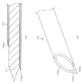
ここで、一般に、上記内視鏡用穿刺針装置に用いられる従来の穿刺針の刃先形状は、図24(a),(b)に示すように通常の注射針の刃先形状と同様な構造となっている。すなわち、従来の穿刺針100は、極細管の先端を切断し、この切断した先端部に少なくとも1つ以上の刃面100aを形成している。なお、ここで、図24(a)は内針(スタイレット)101を突出させた状態の穿刺針100の先端部を示す断面図、図24(b)は従来の穿刺針100の先端部を示す斜視図である。
Here, in general, the cutting edge shape of a conventional puncture needle used in the above-described puncture needle device for an endoscope has the same structure as the cutting edge shape of a normal injection needle as shown in FIGS. 24 (a) and 24 (b). It has become. That is, the
しかしながら、一般に注射針は、生体組織に刺入することを本来の目的としている。上記のように注射針の刃先形状と同様な構造に形成している従来の穿刺針は、この刃先が生体組織を切り裂きながら刺入するため、生体組織を積極的に内部に取り込む構造になっていない。そのため、上記従来の穿刺針は、被検体部の状態、例えば、生体組織が硬い場合には、内部に検体が採取されない場合があったり、又は検体が採取されたとしても極微量な量でしかなかった。また、シリンジ等によって針内部を陰圧にして組織を吸引する吸引生検を行う場合には、生体組織がばらばらに採取されてしまうという不都合がある。 However, in general, an injection needle is originally intended to be inserted into a living tissue. As described above, the conventional puncture needle formed in the same structure as the shape of the cutting edge of the injection needle has a structure in which the living tissue is actively taken into the inside because the cutting edge inserts while cutting the living tissue. Absent. For this reason, the conventional puncture needle may not be collected in the state of the subject part, for example, when the living tissue is hard, or only a very small amount is collected even if the sample is collected. There wasn't. In addition, when performing a suction biopsy in which the inside of the needle is subjected to negative pressure with a syringe or the like and sucks the tissue, there is a disadvantage that the biological tissue is collected in pieces.
他の従来の内視鏡用穿刺針装置としては、例えば、特開平10−216134号公報に記載されているように、上記穿刺針を挿通して進退自在な内針の側部に切り欠き部を形成した構成の装置が提案されている。
上記特開平10−216134号公報に記載の内視鏡用穿刺針装置は、上記内針を突出させて切り欠き部に被検体部の生体組織を挟み込んだ後、上記穿刺針を前進させて上記内針を収納することで生体組織を切断して検体を採取するようになっている。
As another conventional puncture needle device for an endoscope, for example, as described in Japanese Patent Application Laid-Open No. 10-216134, a notch is formed in a side portion of an inner needle that is inserted and retracted through the puncture needle. An apparatus having a configuration in which is formed is proposed.
In the endoscope puncture needle device described in Japanese Patent Laid-Open No. 10-216134, the puncture needle is moved forward by causing the inner needle to protrude and sandwiching the living tissue of the subject portion into the notch. By storing the inner needle, the living tissue is cut and the sample is collected.
しかしながら、上記特開平10−216134号公報に記載の内視鏡用穿刺針装置は、検体を細長く採取することが可能であるが、切り欠き部の機械的強度を確保するために、切り欠きの深さが制限され、十分な厚みの検体を採取することができない。
従って、上記従来の内視鏡用穿刺針装置を用いた生検において、採取された検体量が病理確定診断を行うためには不十分であった場合、十分な量が採取されるまで、繰り返し生検を実施しなければならず、煩雑であった。
However, although the puncture needle device for endoscope described in the above-mentioned Japanese Patent Application Laid-Open No. 10-216134 is capable of collecting a sample long, in order to ensure the mechanical strength of the cutout portion, The depth is limited, and a specimen with sufficient thickness cannot be collected.
Therefore, in the biopsy using the conventional endoscopic puncture needle device, if the sample amount collected is insufficient for performing pathological diagnosis, it is repeated until a sufficient amount is collected. A biopsy had to be performed and was cumbersome.
また、一般に、採取した検体の診断法には、細胞診と組織診との2通りがある。細胞診は、一つ一つの細胞を診て診断するものである。このため、細胞診では、検体が良性なのか悪性なのかの判断が難しく、病理確定診断に至るまでの情報が得られ難い。 In general, there are two types of diagnostic methods for collected specimens: cytology and histology. In cytodiagnosis, each cell is diagnosed and diagnosed. For this reason, in cytodiagnosis, it is difficult to determine whether a specimen is benign or malignant, and it is difficult to obtain information up to the pathological diagnosis.
一方、組織診は、生体組織が集まった1つの塊を全体的に診て診断する方法であるので、病理確定診断を行うのに足り得る情報が容易に得られる。
従って、病理確定診断を行う際には、組織診が行えるような検体量としてある程度の組織状の塊として検体を採取することが望ましい。
Therefore, when performing pathological confirmation diagnosis, it is desirable to collect the sample as a certain amount of tissue-like mass as the amount of the sample that can be histologically diagnosed.
解決しようとする問題点は、従来の内視鏡用穿刺針装置では、病理確定診断を行うための十分な大きさの検体量を採取することが困難であった点である。 The problem to be solved is that it has been difficult for a conventional endoscope puncture needle device to collect a sufficient amount of sample for pathological confirmation diagnosis.
本発明の請求項1に記載の内視鏡用穿刺針装置は、内視鏡の処置具挿通用チャンネルに挿脱自在なシースと、前記シースに挿通して進退自在に体腔内の被検体部に穿刺し、生体組織を採取する管状に形成された長尺な穿刺針と、前記シースの基端側に設け、前記穿刺針の進退を操作する操作部と、この操作部に設け、前記穿刺針を突出させるための突出機構と、を具備し、前記穿刺針の先端部の外周面、内周面の少なくとも一方に先端に向かって尖鋭となる斜面状の刃面を形成したことを特徴としている。
また、本発明の請求項2に記載の発明は、請求項1に記載の内視鏡用穿刺針装置において、前記穿刺針に挿通して進退自在な内針を有し、前記穿刺針は、前記内針を前記穿刺針の先端部から突出させたとき、前記穿刺針の先端部の外周面、内周面の少なくとも一方に先端に向かって尖鋭となる斜面状に形成した刃面が前記内針とともにほぼ連続する傾斜を形成するようにしたことを特徴としている。
The puncture needle device for an endoscope according to
The invention according to
本発明の内視鏡用穿刺針装置は、病理確定診断を行うための十分な検体量を容易に採取することが可能であるという利点を有する。 The puncture needle device for endoscope of the present invention has an advantage that it is possible to easily collect a sufficient amount of sample for performing pathological confirmation diagnosis.
以下、図面を参照して本発明の実施例を説明する。 Embodiments of the present invention will be described below with reference to the drawings.
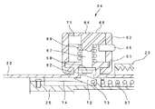
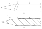
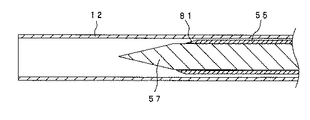
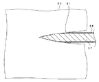
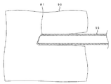
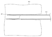
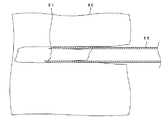
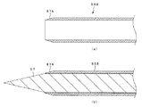
図1ないし図16は本発明の第1実施例に係わり、図1は第1実施例の内視鏡用穿刺針装置が内視鏡の処置具挿入口に取り付けられている状態を示す説明図、図2は図1の内視鏡用穿刺針装置の外観図、図3は図2の内視鏡用穿刺針装置の断面図、図4は図3のコイルシースを示す外観図、図5は図3の穿刺針部を示す説明図、図6は図3のスイッチ部を示す断面説明図、図7は図5の穿刺針の先端側を示す説明図であり、図7(a)は穿刺針の先端側外観図、図7(b)は同図(a)の断面図、図8は内視鏡用穿刺針装置の前半側の動作を示す説明図であり、図8(a)は穿刺針の先端がコイルシースに収容されている穿刺準備状態を示す断面図、図8(b)は第3スライド部を最大限に前進させて、穿刺針の先端がコイルシース先端より突出している状態を示す断面図、図8(c)は内針を抜去した状態を示す断面図、図9は内視鏡用穿刺針装置の後半側の動作を示す説明図であり、図9(a)は調整筒を回転させて突出長を設定している状態を示す断面図、図9(b)は穿刺針の先端を設定した突出長の長さだけ高速に突出している状態を示す断面図、図9(c)は穿刺針装置を内視鏡の処置具挿通用チャンネルから抜去する際に第3スライド部を最大限に基端側に引いている状態を示す断面図、図10は穿刺針部の先端がコイルシースに収容されている穿刺準備状態を示す説明図、図11は穿刺針部の先端をコイルシース先端より突出させて被検体部の手前まで前進させた際の状態を示す説明図、図12は穿刺針部の先端を被検体部に刺入し、目標病変部内まで導いている際の状態を示す説明図、図13は穿刺針部の先端が目標病変部内まで到達して内針を抜去した際の状態を示す説明図、図14はスイッチ部を操作して穿刺針部を目標病変部内へ深く刺入した際の状態を示す説明図、図15は穿刺針部の先端が検体を取り込んだままの状態で目標病変部内から抜去している際の状態を示す説明図、図16は穿刺針の変形例を示す説明図であり、図16(a)は変形例の穿刺針を示す断面図、図16(b)は同図(a)の穿刺針に内針が挿通している際の断面図である。 FIGS. 1 to 16 relate to the first embodiment of the present invention, and FIG. 1 is an explanatory view showing a state in which the endoscope puncture needle device of the first embodiment is attached to the treatment instrument insertion port of the endoscope. 2 is an external view of the puncture needle device for endoscope of FIG. 1, FIG. 3 is a cross-sectional view of the puncture needle device for endoscope of FIG. 2, FIG. 4 is an external view showing the coil sheath of FIG. 3 is an explanatory view showing the puncture needle part of FIG. 3, FIG. 6 is a cross-sectional explanatory view showing the switch part of FIG. 3, FIG. 7 is an explanatory view showing the distal end side of the puncture needle of FIG. 7B is a cross-sectional view of FIG. 7A, FIG. 8 is an explanatory view showing the operation of the first half side of the puncture needle device for an endoscope, and FIG. FIG. 8B is a cross-sectional view showing a puncture preparation state in which the tip of the puncture needle is accommodated in the coil sheath, and FIG. 8B is a diagram illustrating a state in which the third slide portion is advanced to the maximum extent. FIG. 8C is a cross-sectional view showing a state where the inner needle has been removed, and FIG. 9 is an explanatory view showing the operation of the second half side of the puncture needle device for endoscope. 9A is a cross-sectional view showing a state in which the adjustment cylinder is rotated to set the protruding length, and FIG. 9B shows a state in which the tip of the puncture needle protrudes at a high speed by setting the protruding length. FIG. 9C is a cross-sectional view, and FIG. 9C is a cross-sectional view showing a state in which the third slide portion is pulled to the maximum proximal side when the puncture needle device is removed from the treatment instrument insertion channel of the endoscope. FIG. 11 is an explanatory view showing a puncture preparation state in which the tip of the puncture needle is housed in the coil sheath, and FIG. 11 shows a state when the tip of the puncture needle is protruded from the tip of the coil sheath and advanced to the front of the subject part. FIG. 12 shows the tip of the puncture needle portion inserted into the subject portion and led into the target lesion portion. FIG. 13 is an explanatory view showing a state when the tip of the puncture needle portion reaches the target lesion portion and the inner needle is removed, and FIG. 14 is a diagram showing the state where the puncture needle portion is targeted by operating the switch portion. FIG. 15 is an explanatory view showing a state when deeply inserted into the lesioned part, FIG. 15 is an explanatory view showing a state when the tip of the puncture needle part is removed from the target lesioned part with the sample taken in, and FIG. FIG. 16A is an explanatory view showing a modified example of the puncture needle, FIG. 16A is a cross-sectional view showing the modified example of the puncture needle, and FIG. 16B is a plan view of the puncture needle of FIG. FIG.
図1に示すように本実施例の内視鏡用穿刺針装置(以下、単に穿刺針装置という)1は、超音波内視鏡あるいは内視鏡2の図示しない処置具挿通用チャンネルを介して体腔内に導かれるようになっている。
内視鏡2は、体腔内に挿入される細長の挿入部3と、この挿入部3の後端に設けられた操作部4と、この操作部4の後端に配置された接眼部5と、図示しない光源装置に接続されるコネクタ7を有するユニバーサルコード6とを備えている。なお、図示の内視鏡2は、光学式内視鏡であるが、この内視鏡の前記接眼部5にテレビカメラヘッドを取り付けることにより、内視鏡光学像を光電変換して図示しないカメラコントロールユニット(以下、CCU)に接続することで内視鏡画像を得られるようにも使用される。また、本実施例に用いられる内視鏡としては、電子式内視鏡として挿入部先端部内に撮像光学系及び撮像装置を内蔵し、信号線を操作部から延出する前記ユニバーサルコードの末端に設けられたコネクタを介してCCUに接続して内視鏡画像を得られる内視鏡であっても良いことは、勿論である。
As shown in FIG. 1, an endoscope puncture needle device (hereinafter simply referred to as a puncture needle device) 1 according to the present embodiment is passed through an ultrasonic endoscope or a treatment instrument insertion channel (not shown) of the
The
前記内視鏡の操作部4の前端側には、例えば前記穿刺針装置1などの処置具を挿入する処置具挿入口8が設けられている。この処置具挿入口8は、図示しない処置具挿通用チャンネルに連通している。処置具挿通用チャンネルは、挿入部3内に配置され、挿入部先端部3aに形成されている処置具導出口9aに開口している。このため、穿刺針装置1は、前記処置具挿入口8から処置具挿通用チャンネル内に挿通することによって、先端側の穿刺針部11を処置具導出口9aから突出することができるようになっている。
On the front end side of the
図2に示すように前記穿刺針装置1は、体腔内の被検体部に穿刺する穿刺針部11(図5参照)と、この穿刺針部11が挿通されて前記内視鏡の処置具挿通用チャンネルを介して体腔内に挿入するコイルシース12(図4参照)と、このコイルシース12を内部に配設し、後端側から挿入した前記穿刺針部11を前記コイルシース12に挿通した状態で該穿刺針部11を先端側へ突出させるための突出機構を設けた操作部としての補助器具本体13とで主に構成されている。
As shown in FIG. 2, the
前記補助器具本体13は、前記穿刺針部11を突出させる突出機構を備え、前記内視鏡2の前記処置具挿入口8に着脱自在な固定部21aを備えた中空構造の固定筒21と、この固定筒21の内側で長手方向に移動可能に挿入される中空構造の第1スライド部22と、前記穿刺針部11の突出機構による突出長を調整するための調整筒23と、前記第1スライド部22に進退可能に内設されて後端側に指掛け部24を備えた中空構造の第2スライド部25(図3参照)と、この第2スライド部25に進退可能に挿入されるパイプ部26及びこのパイプ部26の基端側に固定されたパイプ口金27を備えた中空構造の第3スライド部28とで主に構成されている。
The
次に、図3を用いて、前記補助器具本体13の内部構造を説明する。
前記固定筒21の一側面には、長手方向に溝31が設けられており、第1固定ネジ32が前記溝31を通して前記第1スライド部22の先端付近に螺合している。この第1スライド部22の基端側外周には、雄ねじ部33が設けられている。この雄ねじ部33には、前記調整筒23の雌ねじが螺合している。前記第1スライド部22の中央付近には、前記穿刺針部11を突出させるためのスイッチ部34が設けられている。
Next, the internal structure of the
A
前記調整筒23は、先端側が雄ねじ部33と螺合可能に開口し、後端側には前記第2スライド部25を構成する細径部35が貫通する穴を形成した平坦な調整筒底部36を有している。前記調整筒23は、この内部に前記第2スライド部25を前記第1スライド部22に対して先端側に付勢する付勢部材としてのコイルばね37を設けている。
The
前記調整筒23は、前記第1スライド部22に対して回転させることにより前後し、基端側へは前記調整筒底部36が前記指掛け部24のダンパ38に接するまで移動可能である。そして、前記調整筒23は、前記調整筒底部36と前記ダンパ38との間の距離で突出機構による突出長(コイルばね37の付勢力により穿刺針部11が突出する長さ)39を定義している。なお、後述する図8(a)の状態では、前記調整筒23が最も先端側に位置しているので、前記突出長39が最大突出長40である。
The
前記第2スライド部25は、先端側から順に太径部41と、前記細径部35と、前記指掛け部24とで構成されている。前記太径部41と前記細径部35とは、前記第1スライド部22内に挿入されている。前記太径部41は、前記第1スライド部22の内径よりやや小さい程度の外径を有している。前記細径部35は、前記コイルばね37の内径より細い外径のパイプ状の部材であり、前記第3スライド部28のパイプ部26を挿入している。
The
前記第2スライド部25の前記細径部35の外側で前記第1スライド部22の内側には、前記コイルばね37が挿入されている。このコイルばね37の基端側は、前記第1スライド部22の基端側に固定されて、先端側は前記第2スライド部25の前記太径部41の基端側に固定されている。このコイルばね37は、圧縮ばねであり、上述したように前記第2スライド部25を前記第1スライド部22に対して常に先端側に付勢している。
The
前記指掛け部24には、先端側に円盤状のダンパ固定板42と基端側に円盤状の指掛け板43が備えられている。前記指掛け部24の中心付近には、長手軸と垂直に前記第2固定ネジ44が螺合している。前記ダンパ固定板42の先端側には、ゴム等の衝撃吸収性のある材料で形成されたリング状の前記ダンパ38が固定されている。前記指掛け部24の内径の一部には、円環状の溝部45が形成されており、ゴム等の材料で形成された弾性リング46がはめ込まれている。この弾性リング46の内径は、前記第3スライド部28の前記パイプ部26の外径よりやや小さくなっている。
The
前記第2スライド部25の細径部35の外周には、前記ダンパ38の先端側の面をゼロとして先端側に向けて目盛り47(図2参照)が形成されている。この目盛り47は、前記ダンパ38と前記調整筒底部36との間によって定義される前記突出長39を示している。
A scale 47 (see FIG. 2) is formed on the outer periphery of the small-
前記パイプ部26の外面には、円環状の溝である二つのクリック溝が形成されており、それぞれ基端側の溝が第1クリック溝48、先端側の溝が第2クリック溝49となっている。これら第1クリック溝48、第2クリック溝49は、前記弾性リング46が嵌ったときに、軽い係止力を発生させ、さらに操作者にクリック感を感じさせる程度の溝である。
Two click grooves, which are annular grooves, are formed on the outer surface of the
前記第2クリック溝49は、前記第1クリック溝48の先端側に形成されている。これら第1クリック溝48と第2クリック溝49との距離は、前記最大突出長40以上になっている。また、前記第3スライド部28の前記パイプ口金27の基端は、雄ねじのルアー口金50になっている。
The
なお、前記第3スライド部28の前記パイプ部26表面には、彩色されたリングで構成される穿刺針退避指標(不図示)を設けることが可能であり、前記第3スライド部28が完全に基端側に引っ張られ、前記第2クリック溝49にてクリック状態になった時にのみ視認可能になる位置に設けられている。(図2では、前記第3スライド部がより先端側に位置しているため、前記第2スライド部25の内部に位置して視認できないようになっている。)
この穿刺針退避指標によって、操作者は間接的に前記穿刺針部11が前記コイルシース12内に収容されていることが認識できて、この穿刺針退避指標を確認してから前記内視鏡2から抜去することで、抜去の際に前記穿刺針部11で前記内視鏡2の処置具挿通用チャンネルを穿孔することが防止できるようになっている。
It is possible to provide a puncture needle retraction index (not shown) composed of a colored ring on the surface of the
From this puncture needle retraction index, the operator can indirectly recognize that the
次に、図4を用いて、前記補助器具本体13の前記第1スライド部22に着脱可能に固定されている前記コイルシース12を説明する。
前記コイルシース12は、コイルシース挿入部51と、コイルシース基端部52と、コイルシース口金部53とから構成されている。
Next, the
The
前記コイルシース挿入部51は、前記内視鏡2の処置具挿通用チャンネルと同程度の長さを有し、可撓性を有する金属製のコイルで構成されている。このコイルシース挿入部51は、前記穿刺針部11の外径よりも大きな内径で且つ前記内視鏡2の処置具挿通用チャンネルより小さな外径を有しており、前記内視鏡2の処置具挿通用チャンネルに挿脱自在になっている。前記コイルシース挿入部51は、前記コイルシース口金部53に取り付けて組み合わせた状態において、前記固定筒21を貫通して先端側に突出するようになっている。
The coil sheath insertion portion 51 has the same length as the treatment instrument insertion channel of the
前記コイルシース口金部53は、前記補助器具本体13の前記第1スライド部22の先端に対して着脱可能に螺合するようになっている。前記コイルシース基端部52は、前記コイルシース口金部53の基端側に接続されている。前記コイルシース基端部52は、前記コイルシース挿入部51と同様のコイルで構成されており、前記補助器具本体13の前記第3スライド部28の途中まで挿入されるようになっている。
The
次に図5を用いて、体腔内の被検体部に穿刺する前記穿刺針部11を説明する。
前記穿刺針部11は、前記補助器具本体13の前記パイプ口金27に設けられた前記ルアー口金50に着脱可能に装着されるようになっている。前記穿刺針部11は、前記コイルシース12に挿通して進退自在に体腔内の被検体部に穿刺し、生体組織を採取する管状に形成された長尺な穿刺針(内視鏡用穿刺針)55と、この穿刺針55に固定された穿刺針口金56とから構成されている。
Next, with reference to FIG. 5, the
The
前記穿刺針55は、内針(スタイレット)57が進退自在に挿通されるようになっている。この内針57には、内針口金58が固定されている。前記穿刺針口金56と前記内針口金58とは、着脱可能に組み合わされており、前記穿刺針55に前記内針57が挿通された状態において、前記内針57の先端は前記穿刺針55先端より先端側に突出するようになっている。
The
次に図6を用いて、前記補助器具本体13の前記第1スライド部22に設けられている前記スイッチ部34の構造を説明する。
図6に示すように前記スイッチ部34のスイッチ座61は、前記第1スライド部22の中心付近に形成された切り欠き部62の上部側に設けられている。前記スイッチ部34は、前記スイッチ座61に安全装置としての安全リング63とスイッチ機構としてのボタン64とが組み付いている。
Next, the structure of the
As shown in FIG. 6, the switch seat 61 of the
前記安全リング63は、リング状の部材であり、前記スイッチ座61に対して長手軸に垂直な軸回りに回動可能に組み付けられている。この安全リング63の円筒面には、ピン状の部材であるロック指標65が放射状に貫通して固定されている。前記ロック指標65は、前記安全リング63の内面及び外面に突出している。
The
前記ボタン64は、前記安全リング63の内側に組み込まれており、ボタンヘッド66と軸67とプッシャ68とから構成されている。前記ボタンヘッド66は、前記安全リング63の内径と同程度の管状部材である。前記軸67は、前記ボタンヘッド66と同軸の棒状部材であり、前記スイッチ座61に進退自由に貫通している。前記プッシャ68は、前記軸67の他端に固定されており、前記切り欠き部62に挿入可能な大きさを有している。
The button 64 is incorporated inside the
前記軸67の前記スイッチ座61と前記ボタンヘッド66との間には、スイッチばね69が組み込まれている。前記ボタン64は、このスイッチばね69により常に図の上方に付勢されている。前記ボタンヘッド66の下面には、前記ロック指標65が入り込むことのできる凹みとしてスイッチ溝71が形成されている。
A
前記ロック指標65と前記スイッチ溝71とは、略180度ずれた位置関係にあり、前記安全リング63を前記軸67回りに回転操作して前記ロック指標65を前記スイッチ溝71に一致させない限り、前記ボタンヘッド66の底部と前記ロック指標65とが当接することで、前記ボタン64の押下操作を行うことができない規制状態となっている。
The
そして、この状態から前記安全リング63を回動操作して、前記ロック指標65が前記スイッチ溝71と同じ位置になるまで回動すると、前記スイッチ部34は、ロック指標65とスイッチ溝71との位置が一致して、前記ボタン64を押し下げ可能となる。すなわち、前記スイッチ部34は、前記穿刺針部11を突出可能とする規制解除状態とすることができる。
When the
前記第2スライド部25の前記太径部41は、一部が切り欠かれており、前記コイルばね37の付勢力を一時的に係止する係止機構としての掛け金72が組み込まれている。この掛け金72の基端側には、長手軸に垂直な揺動軸73が貫通している。前記掛け金72は、前記揺動軸73を中心に揺動可能に支持されている。この揺動軸73の揺動により、前記掛け金72の先端側は、前記第2スライド部25の前記太径部41外径に収納された状態と前記太径部41から突出した状態とを取り得るようになっている。前記掛け金72の先端側には、板ばね74が取り付けられており、その一端は前記掛け金72の先端側を前記太径部41から突出させるように付勢している。
The large-
図6に示すように前記掛け金72は、先端側が前記第1スライド部22の前記切り欠き部62に係止しており、前記コイルばね37によって先端側に付勢されている前記第2スライド部25が前進するのを阻止している。上述したように前記スイッチ部34は、前記安全リング63を前記軸67回りに回転操作して規制解除状態にし、前記ボタンヘッド66を押し下げることにより、前記プッシャ68が前記切り欠き部62に進入し、この切り欠き部62に係止している前記掛け金72を押し下げると、これら切り欠き部62と掛け金72との係止が解消される。これによって、前記スイッチ部34は、前記第2スライド部25を先端側に付勢している前記コイルばね37の付勢力を解放するようになっている。
As shown in FIG. 6, the
そして、前記穿刺針部11は、前記第2スライド部25が予め設定した前記突出長39だけ高速に前進することにより、後述するように設定した前記突出長39の長さだけ高速に突出し、目標病変部に刺入するようになっている。
The
ここで、従来の穿刺針は、刃先形状が通常の注射針の刃先形状と同様な構造であり、この刃先が生体組織を切り裂きながら刺入するため、生体組織を積極的に内部に取り込む構造になっていない。このため、従来の穿刺針は、被検体部の状態例えば、生体組織が硬い場合、内部に検体が採取されないか、又は検体が採取されたとしても極微量な量である。 Here, the conventional puncture needle has a structure in which the cutting edge shape is the same as that of a normal injection needle, and the cutting edge is inserted while cutting the living tissue, so that the living tissue is actively taken into the structure. is not. For this reason, the conventional puncture needle is in a very small amount even when the state of the subject part, for example, when the living tissue is hard, the specimen is not collected inside, or the specimen is collected.
そこで、本実施例では、先端部の外周面に先端に向かって尖鋭となる斜面状の刃面を形成して穿刺針55を構成したものである。
すなわち、前記穿刺針55は、図7(a),(b)に示すように極細管の先端を長手軸方向に対して斜めに切断して先端部を形成し、この先端部の外周面の全周に先端に向かって尖鋭となる斜面状の刃面81を形成している。なお、図7(a),(b)に示す穿刺針55は、先端側から前記内針57を突出させた状態を表している。
Therefore, in this embodiment, the
That is, as shown in FIGS. 7A and 7B, the
そして、前記穿刺針55は、前記内針57を先端部から突出させたとき、前記刃面81が前記内針57とともにほぼ連続する傾斜を形成するように形成している。
このことにより、前記穿刺針55は、前記内針57を挿入したままでも前記内針57とともに比較的抵抗なく手動でスムーズに被検体部へ深く刺入でき、例えば、被検体部の深部部位に存在している目標病変部へ刺入することが可能となる。
The
Accordingly, the
更に、前記穿刺針55は、前記内針57を抜去した後、上述した操作により前記穿刺針部11を突出させることで、穿刺ルート上の不要な生体組織を取り込むことなく、内部に目標病変部の検体をある程度の組織状の塊として取り込み、周辺組織から切り取ることが可能となる。
Furthermore, the
このように構成される穿刺針装置1の動作を図8ないし図15を用いて説明する。
先ず、内視鏡挿入部3の先端部3aは、目的部位付近に挿入されて位置される。
次に、図10に示すように穿刺針部11の先端がコイルシース12に収容されている状態において、コイルシース12が内視鏡2の処置具挿通用チャンネルに挿入され、固定部21aが処置具挿入口8に固定される。このとき、穿刺針部11の先端は、内視鏡挿入部3の先端部3a内に挿入しているコイルシース12の先端よりわずかに基端側に位置してコイルシース12内に収容される。
The operation of the
First, the distal end portion 3a of the
Next, in the state where the tip of the
このとき、図8(a)に示すように第1固定ネジ32は締め込んだ状態であり、上述したように調整筒23が最も先端側に位置している。このため、穿刺針部11の突出長39は、最大突出長40となる。
また、第1クリック溝48は、弾性リング46にはまっている状態である。掛け金72の先端側は、第1スライド部22の切り欠き部62に係止しており、コイルばね37の付勢力によって先端側に付勢されている第2スライド部25が前進するのを阻止している。
At this time, as shown in FIG. 8A, the first fixing
Further, the
次に第1固定ネジ32をゆるめ、第1スライド部22を先端側に前進させると、固定筒21の溝31に案内されて、第1スライド部22が前方に移動する。
そして、内視鏡2の光学視野もしくは超音波画像の観察下において、コイルシース12先端は、被検体部90付近まで前進させられる。そして、再び第1スライド部22が第1固定ネジ32を締め込まれて固定される。
Next, when the first fixing
Then, under the observation of the optical field of view of the
次に第2固定ネジ44がゆるめられ、第3スライド部28が第2スライド部25に対して進退可能にされる。そして、第3スライド部28は、パイプ口金27を把持して前進される。第3スライド部28は、弾性リング46と第1クリック溝48によって軽い係止力で係止されているが、手動により容易に係止を解除でき、前進させることができる。
Next, the second fixing
すると、図8(b)に示すように穿刺針部11が前進し、穿刺針部11先端がコイルシース12先端より突出する。なお、図8(b)では、補助器具本体13は、第3スライド部28を最大限に前進させた状態を示している。この操作により、図示しない超音波観測装置により得た超音波画像の観察下において、穿刺針部11は、図11に示すように被検体部90の手前まで前進され、図12に示すように被検体部90に刺入されて、目標病変部内まで導かれる。このとき、穿刺針部11は、穿刺針55が内針57とともに比較的抵抗なく手動でスムーズに被検体部へ深く刺入できる。
Then, as shown in FIG. 8B, the
穿刺針部11先端が目標病変部内まで到達したら、図8(c)に示すように内針口金58が穿刺針口金56から外されて、図13に示すように内針57が抜去される。
次に検体を採取したい距離、すなわちコイルばね37によって突出させたい距離が測定される。操作者は、測定した距離に応じて目盛り47を読みながら、図9(a)に示す調整筒23を回転させて所望の位置まで移動させて突出長39を設定する。
When the tip of the
Next, the distance at which the specimen is to be collected, that is, the distance at which the specimen is to be projected by the
次に、第2固定ネジ44が締め込まれ、第3スライド部28を第2スライド部25に対して進退不能にしておく。これはコイルばね37による突出時に第3スライド部28が後退してしまうのを防止するためである。
次に、操作者は、スイッチ部34を操作して突出機構により穿刺針部11を自動で突出させる。ここで、更に吸引を行うことによって、検体(組織)は、穿刺針55の内部により取り込まれ易くなる。このため、穿刺針口金56に図示しない吸引装置を接続して吸引を行っても良い。
Next, the second fixing
Next, the operator operates the
スイッチ部34は、図6で説明した規制状態から安全リング63を回動操作され、ロック指標65がスイッチ溝71と同じ位置になるまで回される。ロック指標65は、安全リング63の外面にも突出しているので、ロック指標65の位置は操作者に視覚的にも触覚的にも把握可能である。そして、ロック指標65とスイッチ溝71との位置が一致するとボタン64が押し下げ可能となる。
The
ここで、スイッチ部34のボタンヘッド66を押し下げると、切り欠き部62と掛け金72との係止が解除される。
そして、図9(b)に示すようにコイルばね37の付勢力で先端側に付勢されている第2スライド部25が、突出長39だけ高速に前進する。このとき、ダンパ38は、第3スライド部28が調整筒23に衝突する際の衝撃を吸収するようになっている。
Here, when the button head 66 of the
Then, as shown in FIG. 9B, the
このとき、第3スライド部28は、第2固定ネジ44によって第2スライド部25に固定されており、さらに穿刺針部11が第3スライド部28に固定されている。このため、第2スライド部25が突出長39だけ高速に前進すると共に、第3スライド部28も突出長39だけ高速に前進するのに伴って、穿刺針部11も同時に高速に前進する。すなわち、ボタン64のボタンヘッド66を押下操作することにより、穿刺針部11の先端は設定した突出長39の長さだけ高速に突出する。
At this time, the
すると、穿刺針部11は、図14に示すように目標病変部内へ深く刺入される。そして、図7(a),(b)で説明したように穿刺針55は、内部に目標病変部の検体をある程度の組織状の塊として取り込み、周辺組織から切り取ることができる。
Then, the
そして、第2固定ネジ44が緩められ、図9(c)に示すように第3スライド部28が基端側に最大限に引かれる。すると、図15に示すように穿刺針部11の先端は、検体を取り込んだままの状態で目標病変部内から抜去される。そして、穿刺針部11は、コイルシース12内に収容される。次に固定部21aの係合が解除されて穿刺針装置1が内視鏡の処置具挿通用チャンネルから抜去される。
この結果、本実施例の穿刺針装置1は、病理確定診断を行うために十分な検体量を1回で採取することができ、手術時間の短縮が可能となる。
Then, the second fixing
As a result, the
なお、前記穿刺針は、図16(a),(b)に示すように先端部を形成しても良い。
図16(a),(b)に示すように、穿刺針55Bは、極細管の先端を長手軸方向に対して垂直に切断して先端部を形成し、この先端部の外周面の全周に先端に向かって尖鋭となる斜面状の刃面81bを形成している。
The puncture needle may have a tip as shown in FIGS. 16 (a) and 16 (b).
As shown in FIGS. 16 (a) and 16 (b), the puncture needle 55B cuts the tip of the microtubule perpendicularly to the longitudinal axis direction to form the tip, and the entire circumference of the outer peripheral surface of this tip An
これにより、本変形例の穿刺針55Bは、上記第1実施例とほぼ同様な効果を得ることに加え、内針57とともに形成される傾斜が更に連続的であるのでよりスムーズに目標病変部内へ刺入できる。更に、本変形例の穿刺針55Bは、先端が垂直であるので、組織が逃げず、より多くの検体が取れる。
As a result, the puncture needle 55B according to the present modification obtains substantially the same effect as that of the first embodiment, and the inclination formed with the
なお、本実施例の穿刺針は、先端に向かって尖鋭となる斜面状の刃面を、先端部の全周に形成しているが、前記先端部の略半周に形成しても良いし、前記先端部の円周に沿って間欠的に形成しても良く、或いは前記先端部の一部を残し略全周に形成してもよいものである(この点は、後術する第2実施例及び各変形例にも同様に当てはまる。)。 The puncture needle of this example has a sloped blade surface that is sharp toward the tip, but is formed on the entire circumference of the tip, but may be formed on a substantially half circumference of the tip, It may be formed intermittently along the circumference of the tip portion, or may be formed on the entire circumference leaving a part of the tip portion (this point is a second operation to be performed later). The same applies to the examples and variations.)
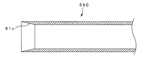
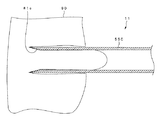
図17ないし図23は本発明の第2実施例に係わり、図17は第2実施例の穿刺針を示す断面図、図18は穿刺針を目標病変部の手前に導いた際の状態を示す説明図、図19は吸引を行って目標病変部を穿刺針の内部に引き込んだ際の状態を示す説明図、図20はスイッチ部を操作して穿刺針を目標病変部内へ深く刺入した際の状態を示す説明図、図21は穿刺針の先端が検体を取り込んだままの状態で目標病変部内から抜去されている際の状態を示す説明図、図22は穿刺針の変形例を示す説明図であり、図22(a)は第1変形例の穿刺針の断面図、図22(b)は第2変形例の穿刺針の断面図、図22(c)は第3変形例の穿刺針の断面図、図23は更なる穿刺針の変形例を示す説明図であり、図23(a)は第4変形例の穿刺針の断面図、図23(b)は第5変形例の穿刺針の断面図である。 FIGS. 17 to 23 relate to a second embodiment of the present invention, FIG. 17 is a cross-sectional view showing the puncture needle of the second embodiment, and FIG. 18 shows a state when the puncture needle is guided before the target lesion site. FIG. 19 is an explanatory diagram showing a state when the target lesion is drawn into the puncture needle by performing suction, and FIG. 20 is when the puncture needle is deeply inserted into the target lesion by operating the switch unit. FIG. 21 is an explanatory view showing a state when the tip of the puncture needle is removed from the target lesion while the specimen is taken in, and FIG. 22 is an explanatory view showing a modification of the puncture needle. 22 (a) is a cross-sectional view of a puncture needle of a first modification, FIG. 22 (b) is a cross-sectional view of a puncture needle of a second modification, and FIG. 22 (c) is a puncture of a third modification. 23 is an explanatory view showing a further modification of the puncture needle, and FIG. 23 (a) is a sectional view of the puncture needle of the fourth modification. Figure, FIG. 23 (b) is a sectional view of the puncture needle of the fifth modification.
上述した第1実施例は、前記穿刺針の先端部に対して外周面の全周に先端に向かって尖鋭となる斜面状の刃面を形成して構成しているが、第2実施例は前記穿刺針の先端部に対して内周面の全周に先端に向かって尖鋭となる斜面状の刃面を形成して構成する。それ以外の構成は上記第1実施例と同様であるので説明を省略し、同一構成には同じ符号を付して説明する。 In the first embodiment described above, a sloped blade surface that is sharp toward the tip is formed on the entire circumference of the outer peripheral surface with respect to the tip of the puncture needle. An inclined blade surface that is sharp toward the tip is formed on the entire circumference of the inner peripheral surface with respect to the tip of the puncture needle. Since the other configuration is the same as that of the first embodiment, the description thereof will be omitted, and the same components will be described with the same reference numerals.
すなわち、図17に示すように第2実施例の穿刺針装置は、極細管の先端を長手軸方向に対して垂直に切断(変形例として斜めに切断しても良い。)して先端部を形成し、この先端部の内周面の全周に先端に向かって尖鋭となる斜面状の刃面81cを形成した穿刺針55Cを設けている。
That is, as shown in FIG. 17, in the puncture needle device of the second embodiment, the tip of the microtubule is cut perpendicularly to the longitudinal axis direction (or may be cut obliquely as a modification). A
この構成により、前記穿刺針55Cは、前記被検体部90への刺入時、前記刃面81cによって目標病変部の検体を切り取り、内部にある程度の組織状の塊として取り込むことが可能となる。なお、それ以外の構成は、上記第1実施例とほぼ同様なので説明を省略する。
With this configuration, when the
このように構成される第2実施例の穿刺針装置の動作を図18ないし図21を用いて説明する。なお、第2実施例の穿刺針装置は、目標病変部が体表近くの被検体部90に存在している場合において用いられる。
The operation of the puncture needle device of the second embodiment configured as described above will be described with reference to FIGS. Note that the puncture needle device of the second embodiment is used when the target lesion is present in the
このため、第2実施例の穿刺針装置は、最初から内針57が必要なく、上記第1実施例の図8及び図9において、内針口金58が穿刺針口金56から外されて内針57が抜去された状態において用いられる。それ以外の第2実施例の穿刺針装置の動作は、図18に示すように穿刺針部11を被検体部90の手前に導くまでは、上記第1実施例の図8及び図9とほぼ同様(但し、内針口金58が穿刺針口金56から外されて内針57が抜去された状態)であり、説明を省略する。
次に、操作者は、穿刺針部11先端から検体を採取したい所定の距離を測定し、設定する。そして、操作者は、スイッチ部34を操作して突出機構により穿刺針部11を自動で突出させる。
For this reason, the puncture needle device of the second embodiment does not require the
Next, the operator measures and sets a predetermined distance from which the sample is to be collected from the tip of the
ここで、更に吸引を行うことによって、検体(組織)は、穿刺針55Cの内部により取り込まれ易くなる。このため、前記穿刺針口金56に図示しない吸引装置を接続して吸引を行う。図19に示すように、穿刺針部11の穿刺針55Cは、前記吸引によって目標病変部の一部を内部に引き込む。
そして、スイッチ部34が操作されると、穿刺針部11は、設定された突出長39の長さだけを高速に突出する。すると、穿刺針部11の穿刺針55Cは、図20に示すように目標病変部内へ深く刺入されて、その内部に検体をある程度の組織状の塊として取り込み、周辺組織から切り取る。
Here, by further aspirating, the specimen (tissue) is easily taken into the
And if the
次に、第3スライド部28が基端側に最大限に引かれることにより、図21に示すように穿刺針部11の穿刺針55C先端が検体を取り込んだままの状態で目標病変部内から抜去され、コイルシース12内に収容される。そして、穿刺針装置は、内視鏡の処置具挿通用チャンネルから抜去される。
Next, when the
これにより、第2実施例の穿刺針装置は、穿刺針55Cの刃面81cが先端部の内周面に形成されているので、穿刺針55Cの刺入によって切り取られた検体(組織)がその内部により積極的に取り込まれ易くなるという効果を得ることができる。
Thereby, in the puncture needle device of the second embodiment, since the
なお、前記穿刺針は、図22(a)〜(c)に示すような先端形状に形成しても良い。
図22(a)に示す穿刺針55Dは、上記第2実施例の穿刺針55Cに対して内周面に、組織引っかけ保持用の段部81dを形成して構成されている。この構成により、前記穿刺針55Dは、目的部位内へ刺入した後、内部に入った検体を前記段部81dにより引っ掛けて切り取ることで、周辺組織からより切り取り易く、また切り取った検体(組織)が脱落しにくくなる。従って、前記穿刺針55Dは、内部に取り込んだ検体に対して周辺組織からの切り取り、回収の効果を更に高めることが可能となり、検体採取性が更に向上する。
In addition, you may form the said puncture needle in the front-end | tip shape as shown to Fig.22 (a)-(c).
A puncture needle 55D shown in FIG. 22A is configured by forming a step portion 81d for holding and holding a tissue on the inner peripheral surface of the
また、図22(b)に示す穿刺針55Eは、上記第2実施例の穿刺針55Cに対して刃面81eを変位させ(片寄らせ)て形成したものである。この構成により、前記穿刺針55Eは、前記穿刺針55Dと同様に内部に取り込んだ検体に対して周辺組織からの切り取りの効果を更に高めることが可能となり、検体採取性が更に向上する。
A puncture needle 55E shown in FIG. 22 (b) is formed by displacing (biasing) the blade surface 81e with respect to the
さらに、図22(c)に示す穿刺針55Fは、先端部の内周面及び外周面の両面全周に先端に向かって尖鋭となる斜面状の刃面81bを形成して構成したものである。この構成により、前記穿刺針55Fは、被検体部への刺入の効果を更に高めることが可能となり、刺入性が向上する。
Furthermore, the puncture needle 55F shown in FIG. 22 (c) is configured by forming a
さらにまた、前記穿刺針は、図23(a),(b)に示すような先端部の形状に形成しても良い。
図23(a)に示す穿刺針55Gは、極細管の先端を長手軸方向に対して湾曲状にえぐって切断して先端部を形成し、この先端部の内周面の全周に先端に向かって尖鋭となる斜面状の刃面81gを形成している。この構成により、前記穿刺針55Gは、検体が比較的硬い場合や繊維質の場合に穴あけパンチ状に刺入して被検体部への刺入の効果を更に高めることが可能となり、刺入性が向上する。
Furthermore, the puncture needle may be formed in the shape of the tip as shown in FIGS. 23 (a) and 23 (b).
The
また、図23(b)に示す穿刺針55Hは、前記穿刺針55Gに対し、更に外周面の中央部付近に斜面状の刃面81hを形成して構成されている。この構成により、前記穿刺針55Hは、前記穿刺針55Gに対し、被検体部への刺入の効果を更に高めることが可能となり、刺入性が向上する。
Further, the puncture needle 55H shown in FIG. 23 (b) is configured by forming an inclined blade surface 81h near the center of the outer peripheral surface of the
なお、本発明は、以上述べた実施例のみに限定されるものではなく、発明の要旨を逸脱しない範囲で種々変形実施可能である。 The present invention is not limited to the above-described embodiments, and various modifications can be made without departing from the spirit of the invention.
[付記]
(付記項1)
内視鏡の処置具挿通用チャンネルに挿脱自在なシースと、
前記シースに挿通して進退自在に体腔内の被検体部に穿刺し、生体組織を採取する管状に形成された長尺な穿刺針と、
前記シースの基端側に設け、前記穿刺針の進退を操作する操作部と、
前記操作部に設け、前記穿刺針を突出させるための突出機構と、
を具備し、
前記穿刺針の先端部の外周面、内周面の少なくとも一方に先端に向かって尖鋭となる斜面状の刃面を形成したことを特徴とする内視鏡用穿刺針装置。
[Appendix]
(Additional item 1)
A sheath that can be inserted into and removed from the treatment instrument insertion channel of the endoscope;
A long puncture needle formed into a tubular shape that penetrates the sheath and punctures a subject part in a body cavity so as to freely advance and retract, and collects a biological tissue;
An operating portion that is provided on the proximal end side of the sheath and operates to advance and retract the puncture needle;
A projecting mechanism for projecting the puncture needle, provided in the operation unit;
Comprising
A puncture needle device for an endoscope, wherein a sloped blade surface that is sharp toward the tip is formed on at least one of an outer peripheral surface and an inner peripheral surface of the tip portion of the puncture needle.
(付記項2)
前記穿刺針は、前記先端に向かって尖鋭となる斜面状の刃面を、前記先端部の外周面、内周面、内外周両面の少なくとも一方に形成したことを特徴とする付記項1に記載の内視鏡用穿刺針装置。
(Appendix 2)
The puncture needle has a slanted blade surface that is sharpened toward the tip, formed on at least one of the outer peripheral surface, the inner peripheral surface, and the inner and outer peripheral surfaces of the tip portion. Endoscopic puncture needle device.
(付記項3)
前記穿刺針に挿通して進退自在な内針を有し、
前記穿刺針は、前記内針を前記穿刺針の先端部から突出させたとき、前記穿刺針の先端部の外周面、内周面の少なくとも一方に先端に向かって尖鋭となる斜面状に形成した刃面が前記内針とともにほぼ連続する傾斜を形成するようにしたことを特徴とする付記項1に記載の内視鏡用穿刺針装置。
(Additional Item 3)
It has an inner needle that is inserted through the puncture needle and can freely advance and retreat,
The puncture needle is formed in an inclined surface that is sharp toward the tip on at least one of the outer peripheral surface and the inner peripheral surface of the tip portion of the puncture needle when the inner needle is protruded from the tip portion of the puncture needle. The puncture needle device for an endoscope according to
(付記項4)
前記穿刺針は、先端部の外周面、内周面、内外周両面の少なくとも一方に、先端に向かって尖鋭となる斜面状の刃面を、前記先端部の全周、略半周、円周に沿って間欠的、或いは一部を残して略全周のいずれかに形成したことを特徴とする付記項1に記載の内視鏡用穿刺針装置。
(Appendix 4)
The puncture needle has a beveled blade surface that sharpens toward the tip on at least one of the outer peripheral surface, inner peripheral surface, and inner and outer peripheral surfaces of the tip portion on the entire circumference, substantially half circumference, and circumference of the tip portion. The puncture needle device for an endoscope according to
(付記項5)
前記穿刺針は、極細管の先端を長手軸方向に対して斜めに切断して先端部を形成し、この先端部の外周面、内周面、内外周両面の少なくとも一方に先端に向かって尖鋭となる斜面状の刃面を形成したことを特徴とする付記項1に記載の内視鏡用穿刺針装置。
(Appendix 5)
The puncture needle cuts the tip of the ultrathin tube obliquely with respect to the longitudinal axis direction to form a tip portion, and sharpens toward the tip on at least one of the outer peripheral surface, inner peripheral surface, and inner and outer peripheral surfaces of the tip portion. The puncture needle device for an endoscope according to
(付記項6)
前記穿刺針は、極細管の先端を長手軸方向に対して垂直に切断して先端部を形成し、この先端部の外周面、内周面、内外周両面の少なくとも一方に先端に向かって尖鋭となる斜面状の刃面を形成したことを特徴とする付記項1に記載の内視鏡用穿刺針装置。
(Appendix 6)
The puncture needle is formed by cutting the tip of an ultrathin tube perpendicularly to the longitudinal direction to form a tip, and sharpens toward the tip on at least one of the outer peripheral surface, inner peripheral surface, and inner and outer peripheral surfaces of the tip. The puncture needle device for an endoscope according to
(付記項7)
前記穿刺針は、極細管の先端を長手軸方向に対して先端側から湾曲状に切断して先端部を形成し、この先端部の外周面、内周面、内外周両面の少なくとも一方に先端に向かって尖鋭となる斜面状の刃面を形成したことを特徴とする付記項1に記載の内視鏡用穿刺針装置。
(Appendix 7)
The puncture needle is formed by cutting the distal end of the ultrathin tube in a curved shape from the distal end side with respect to the longitudinal axis direction to form a distal end portion. The puncture needle device for an endoscope according to
(付記項8)
前記穿刺針は、前記穿刺針の先端部の外周面、内周面、内外周両面の少なくとも一方に先端に向かって尖鋭となる斜面状の刃面を片寄らせ(変位させ)て形成したことを特徴とする付記項1に記載の内視鏡用穿刺針装置。
(Appendix 8)
The puncture needle is formed by offsetting (displacement) a slanted blade surface that is sharp toward the tip on at least one of the outer peripheral surface, inner peripheral surface, and inner and outer peripheral surfaces of the tip portion of the puncture needle. The puncture needle device for an endoscope according to
(付記項9)
前記穿刺針は、極細管の先端を長手軸方向に対して先端側から湾曲状に切断して先端部を形成し、この先端部の外周面、内周面、内外周両面の少なくとも一方に先端に向かって尖鋭となる斜面状の刃面を形成し、更に前記湾曲部の中央部付近に前記刃面を形成したことを特徴とする付記項1に記載の内視鏡用穿刺針装置。
(Appendix 9)
The puncture needle is formed by cutting the distal end of the ultrathin tube in a curved shape from the distal end side with respect to the longitudinal axis direction to form a distal end portion. The puncture needle device for an endoscope according to
(付記項10)
前記穿刺針は、内部に入った生体組織を引っ掛けて切り取るための保持用段部を前記内周面に形成したことを特徴とする付記項1に記載の内視鏡用穿刺針装置。
(Appendix 10)
The puncture needle device for an endoscope according to
(付記項11)
内視鏡の処置具挿通用チャンネルに挿脱自在なシースと、
前記シースを挿通、及び進退自在な穿刺針と、
前記穿刺針を挿通、及び進退自在な内針と、
前記シースの基端側に位置し、前記穿刺針及び前記内針の進退を操作する操作部と、
を有する内視鏡用穿刺針装置において、
前記穿刺針の先端部の外周面あるいは内周面のほぼ全周に斜面状の刃面を形成し、且つ前記操作部に前記穿刺針の突出機構を設けたことを特徴とする内視鏡用穿刺針装置。
(Appendix 11)
A sheath that can be inserted into and removed from the treatment instrument insertion channel of the endoscope;
A puncture needle that is inserted through the sheath and can be advanced and retracted;
An inner needle that can be inserted through the puncture needle and can be advanced and retracted;
An operation unit that is located on the proximal end side of the sheath and operates to advance and retract the puncture needle and the inner needle;
In an endoscope puncture needle device having
An endoscope for an endoscope characterized in that an inclined blade surface is formed on almost the entire outer peripheral surface or inner peripheral surface of the distal end portion of the puncture needle, and a projection mechanism for the puncture needle is provided in the operation portion. Puncture needle device.
(付記項12)
内視鏡の処置具挿通用チャンネルに挿脱自在なシースに挿通して進退自在に体腔内の被検体部に穿刺し、生体組織を採取する管状に形成された長尺な内視鏡用穿刺針であって、
先端部の外周面、内周面、内外周両面の少なくとも一方に、先端に向かって尖鋭となる斜面状の刃面を形成したことを特徴とする内視鏡用穿刺針。
(Appendix 12)
A long endoscope puncture formed into a tubular shape that is inserted into a sheath that can be inserted into and removed from a treatment instrument insertion channel of an endoscope, and punctures a subject part in a body cavity so as to advance and retreat, and collect a living tissue. A needle,
A puncture needle for an endoscope, wherein a sloped blade surface that is sharp toward the tip is formed on at least one of the outer peripheral surface, inner peripheral surface, and inner and outer peripheral surfaces of the tip.
1 穿刺針装置(内視鏡用穿刺針装置)
2 内視鏡
3 挿入部
8 処置具挿入口(処置具挿通用チャンネル入口)
9a 処置具導出口
11 穿刺針部
12 コイルシース
13 補助器具本体
21 固定筒
21a 固定部
22 第1スライド部
23 調整筒
25 第2スライド部
28 第3スライド部
32 第1固定ネジ
34 スイッチ部
37 コイルばね
44 第2固定ネジ
55 穿刺針(内視鏡用穿刺針)
56 穿刺針口金
57 内針
58 内針口金
81 刃面
代理人 弁理士 伊藤 進
1 Puncture needle device (Puncture needle device for endoscope)
2
9a
56
Attorney Susumu Ito
Claims (2)
前記シースに挿通して進退自在に体腔内の被検体部に穿刺し、生体組織を採取する管状に形成された長尺な穿刺針と、
前記シースの基端側に設け、前記穿刺針の進退を操作する操作部と、
前記操作部に設け、前記穿刺針を突出させるための突出機構と、
を具備し、
前記穿刺針の先端部の外周面、内周面の少なくとも一方に先端に向かって尖鋭となる斜面状の刃面を形成したことを特徴とする内視鏡用穿刺針装置。 A sheath that can be inserted into and removed from the treatment instrument insertion channel of the endoscope;
A long puncture needle formed into a tubular shape that penetrates the sheath and punctures a subject part in a body cavity so as to freely advance and retract, and collects a biological tissue;
An operating portion that is provided on the proximal end side of the sheath and operates to advance and retract the puncture needle;
A projecting mechanism for projecting the puncture needle, provided in the operation unit;
Comprising
A puncture needle device for an endoscope, wherein a sloped blade surface that is sharp toward the tip is formed on at least one of an outer peripheral surface and an inner peripheral surface of the tip portion of the puncture needle.
前記穿刺針は、前記内針を前記穿刺針の先端部から突出させたとき、前記穿刺針の先端部の外周面、内周面の少なくとも一方に先端に向かって尖鋭となる斜面状に形成した刃面が前記内針とともにほぼ連続する傾斜を形成するようにしたことを特徴とする請求項1に記載の内視鏡用穿刺針装置。 It has an inner needle that is inserted through the puncture needle and can freely advance and retreat,
The puncture needle is formed in an inclined surface that is sharp toward the tip on at least one of the outer peripheral surface and the inner peripheral surface of the tip portion of the puncture needle when the inner needle is protruded from the tip portion of the puncture needle. The puncture needle device for an endoscope according to claim 1, wherein a blade surface forms a substantially continuous slope together with the inner needle.
Priority Applications (1)
| Application Number | Priority Date | Filing Date | Title |
|---|---|---|---|
| JP2003305570A JP2005073798A (en) | 2003-08-28 | 2003-08-28 | Puncture needle device for endoscope |
Applications Claiming Priority (1)
| Application Number | Priority Date | Filing Date | Title |
|---|---|---|---|
| JP2003305570A JP2005073798A (en) | 2003-08-28 | 2003-08-28 | Puncture needle device for endoscope |
Publications (1)
| Publication Number | Publication Date |
|---|---|
| JP2005073798A true JP2005073798A (en) | 2005-03-24 |
Family
ID=34408889
Family Applications (1)
| Application Number | Title | Priority Date | Filing Date |
|---|---|---|---|
| JP2003305570A Pending JP2005073798A (en) | 2003-08-28 | 2003-08-28 | Puncture needle device for endoscope |
Country Status (1)
| Country | Link |
|---|---|
| JP (1) | JP2005073798A (en) |
Cited By (17)
| Publication number | Priority date | Publication date | Assignee | Title |
|---|---|---|---|---|
| JP2009273890A (en) * | 2008-05-15 | 2009-11-26 | Olympus Medical Systems Corp | Endoscopic apparatus |
| JP2010099429A (en) * | 2008-10-22 | 2010-05-06 | River Seiko:Kk | Endoscopic treatment tool |
| EP2239615A1 (en) | 2009-04-10 | 2010-10-13 | Sumitomo Electric Industries, Ltd. | Optical combiner and image projector using the optical combiner |
| EP2241928A1 (en) | 2009-04-10 | 2010-10-20 | Sumitomo Electric Industries, Ltd. | Optical combiner and image projector using the optical combiner |
| WO2011126109A1 (en) * | 2010-04-08 | 2011-10-13 | 学校法人久留米大学 | Puncture aspiration method and puncture aspiration device |
| WO2014112518A1 (en) | 2013-01-21 | 2014-07-24 | 富士フイルム株式会社 | Tissue sampling device |
| WO2014132672A1 (en) | 2013-02-27 | 2014-09-04 | オリンパスメディカルシステムズ株式会社 | Insertion/removal-support tool for endoscopic instrument |
| WO2014192646A1 (en) | 2013-05-27 | 2014-12-04 | 富士フイルム株式会社 | Tissue sampling device |
| JP2015502802A (en) * | 2011-11-29 | 2015-01-29 | プロメックス・テクノロジーズ・エルエルシー | Complete core biopsy device |
| US9198686B2 (en) | 2010-07-30 | 2015-12-01 | Olympus Corporation | Medical instrument |
| JP5886454B1 (en) * | 2015-02-23 | 2016-03-16 | 応用電子工業株式会社 | Biopsy needle |
| US9693803B2 (en) | 2015-02-27 | 2017-07-04 | Olympus Corporation | Puncture needle for endoscope and biopsy system |
| JP2017524402A (en) * | 2014-06-10 | 2017-08-31 | チャールズ ヴァルテルCharles WALTHER | Endoscopic biopsy instrument |
| CN111084654A (en) * | 2019-12-31 | 2020-05-01 | 山东威高集团医用高分子制品股份有限公司 | Safety blood vessel puncture sheath |
| CN113226191A (en) * | 2019-01-09 | 2021-08-06 | 日本瑞翁株式会社 | Puncture device for endoscope |
| CN113795201A (en) * | 2019-05-17 | 2021-12-14 | 奥林巴斯株式会社 | Puncture needle for endoscope |
| US11849927B2 (en) | 2019-10-09 | 2023-12-26 | Praxis Holding Llc | Telescoping needle assembly with rotating needle |
Citations (6)
| Publication number | Priority date | Publication date | Assignee | Title |
|---|---|---|---|---|
| JPS5843411U (en) * | 1981-09-17 | 1983-03-23 | 株式会社 八光電機製作所 | biopsy needle |
| JPS6327705Y2 (en) * | 1984-05-21 | 1988-07-27 | ||
| JPS646915U (en) * | 1987-07-02 | 1989-01-17 | ||
| JPH08150145A (en) * | 1994-09-29 | 1996-06-11 | Olympus Optical Co Ltd | Sticking needle for endoscope |
| JPH10216134A (en) * | 1997-02-10 | 1998-08-18 | Olympus Optical Co Ltd | Puncture needle system |
| JP2001037765A (en) * | 1999-08-03 | 2001-02-13 | Olympus Optical Co Ltd | Operation assisting appliance for puncture needle for endoscope |
-
2003
- 2003-08-28 JP JP2003305570A patent/JP2005073798A/en active Pending
Patent Citations (6)
| Publication number | Priority date | Publication date | Assignee | Title |
|---|---|---|---|---|
| JPS5843411U (en) * | 1981-09-17 | 1983-03-23 | 株式会社 八光電機製作所 | biopsy needle |
| JPS6327705Y2 (en) * | 1984-05-21 | 1988-07-27 | ||
| JPS646915U (en) * | 1987-07-02 | 1989-01-17 | ||
| JPH08150145A (en) * | 1994-09-29 | 1996-06-11 | Olympus Optical Co Ltd | Sticking needle for endoscope |
| JPH10216134A (en) * | 1997-02-10 | 1998-08-18 | Olympus Optical Co Ltd | Puncture needle system |
| JP2001037765A (en) * | 1999-08-03 | 2001-02-13 | Olympus Optical Co Ltd | Operation assisting appliance for puncture needle for endoscope |
Cited By (26)
| Publication number | Priority date | Publication date | Assignee | Title |
|---|---|---|---|---|
| JP2009273890A (en) * | 2008-05-15 | 2009-11-26 | Olympus Medical Systems Corp | Endoscopic apparatus |
| JP2010099429A (en) * | 2008-10-22 | 2010-05-06 | River Seiko:Kk | Endoscopic treatment tool |
| EP2239615A1 (en) | 2009-04-10 | 2010-10-13 | Sumitomo Electric Industries, Ltd. | Optical combiner and image projector using the optical combiner |
| EP2241928A1 (en) | 2009-04-10 | 2010-10-20 | Sumitomo Electric Industries, Ltd. | Optical combiner and image projector using the optical combiner |
| US9072507B2 (en) | 2010-04-08 | 2015-07-07 | Kurume University | Suction puncture method and suction puncture device |
| WO2011126109A1 (en) * | 2010-04-08 | 2011-10-13 | 学校法人久留米大学 | Puncture aspiration method and puncture aspiration device |
| US9198686B2 (en) | 2010-07-30 | 2015-12-01 | Olympus Corporation | Medical instrument |
| JP2015502802A (en) * | 2011-11-29 | 2015-01-29 | プロメックス・テクノロジーズ・エルエルシー | Complete core biopsy device |
| WO2014112518A1 (en) | 2013-01-21 | 2014-07-24 | 富士フイルム株式会社 | Tissue sampling device |
| US10736613B2 (en) | 2013-01-21 | 2020-08-11 | Fujifilm Corporation | Tissue sampling device |
| WO2014132672A1 (en) | 2013-02-27 | 2014-09-04 | オリンパスメディカルシステムズ株式会社 | Insertion/removal-support tool for endoscopic instrument |
| CN104717915A (en) * | 2013-02-27 | 2015-06-17 | 奥林巴斯医疗株式会社 | Insertion/removal-support tool for endoscopic instrument |
| US9486124B2 (en) | 2013-02-27 | 2016-11-08 | Olympus Corporation | Advance and retreat assist tool for endoscopic treatment instrument |
| US10945711B2 (en) | 2013-05-27 | 2021-03-16 | Fujifilm Corporation | Tissue sampling device |
| WO2014192646A1 (en) | 2013-05-27 | 2014-12-04 | 富士フイルム株式会社 | Tissue sampling device |
| JP2017524402A (en) * | 2014-06-10 | 2017-08-31 | チャールズ ヴァルテルCharles WALTHER | Endoscopic biopsy instrument |
| JP5886454B1 (en) * | 2015-02-23 | 2016-03-16 | 応用電子工業株式会社 | Biopsy needle |
| US9693803B2 (en) | 2015-02-27 | 2017-07-04 | Olympus Corporation | Puncture needle for endoscope and biopsy system |
| CN113226191A (en) * | 2019-01-09 | 2021-08-06 | 日本瑞翁株式会社 | Puncture device for endoscope |
| CN113795201A (en) * | 2019-05-17 | 2021-12-14 | 奥林巴斯株式会社 | Puncture needle for endoscope |
| DE112020001742T5 (en) | 2019-05-17 | 2022-01-05 | Olympus Corporation | ENDOSCOPIC PUNCTURE NEEDLE |
| JP2023123806A (en) * | 2019-05-17 | 2023-09-05 | オリンパス株式会社 | Puncture needle for endoscope |
| JP7442003B2 (en) | 2019-05-17 | 2024-03-01 | オリンパス株式会社 | Puncture needle for endoscope |
| CN113795201B (en) * | 2019-05-17 | 2025-08-08 | 奥林巴斯株式会社 | Endoscopic puncture needle |
| US11849927B2 (en) | 2019-10-09 | 2023-12-26 | Praxis Holding Llc | Telescoping needle assembly with rotating needle |
| CN111084654A (en) * | 2019-12-31 | 2020-05-01 | 山东威高集团医用高分子制品股份有限公司 | Safety blood vessel puncture sheath |
Similar Documents
| Publication | Publication Date | Title |
|---|---|---|
| JP2005073798A (en) | Puncture needle device for endoscope | |
| US7766843B2 (en) | Biopsy method | |
| CN205729413U (en) | Device for aspiration biopsy | |
| US5560373A (en) | Needle core biopsy instrument with durable or disposable cannula assembly | |
| US8758369B2 (en) | Biopsy devices and methods | |
| CN204995517U (en) | Replaceable core biopsy needle | |
| US20070208272A1 (en) | Biopsy device | |
| JP5997297B2 (en) | Tissue collection device | |
| US9844362B2 (en) | Exchangeable core biopsy needle | |
| JP2005520617A (en) | Biopsy needle | |
| JP6239197B2 (en) | Biopsy needle | |
| JP2001104313A (en) | Endoscope tissue collection tool | |
| JP6097826B2 (en) | Tissue collection device | |
| JP2012235878A (en) | Biopsy device | |
| JP3661470B2 (en) | Tissue collection device | |
| EP3292822A2 (en) | Biopsy device | |
| CN106132313B (en) | Rigid scope external member | |
| US20100228147A1 (en) | Puncturing cytodiagnostic device | |
| JP6121085B1 (en) | Biopsy needle | |
| CN110730632B (en) | Puncture needle for endoscope | |
| JP6153697B2 (en) | Biopsy needle | |
| JP2001037765A (en) | Operation assisting appliance for puncture needle for endoscope | |
| US10182798B2 (en) | Exchangeable core biopsy needle | |
| JP2001070307A (en) | Tissue collecting apparatus | |
| JP3732990B2 (en) | Endoscopy tissue collection tool |
Legal Events
| Date | Code | Title | Description |
|---|---|---|---|
| A621 | Written request for application examination |
Free format text: JAPANESE INTERMEDIATE CODE: A621 Effective date: 20050906 |
|
| A131 | Notification of reasons for refusal |
Free format text: JAPANESE INTERMEDIATE CODE: A131 Effective date: 20080902 |
|
| A02 | Decision of refusal |
Free format text: JAPANESE INTERMEDIATE CODE: A02 Effective date: 20090106 |


