WO2016199338A1 - 移動体の位置姿勢推定装置及び移動体の自律走行システム - Google Patents
移動体の位置姿勢推定装置及び移動体の自律走行システム Download PDFInfo
- Publication number
- WO2016199338A1 WO2016199338A1 PCT/JP2016/002189 JP2016002189W WO2016199338A1 WO 2016199338 A1 WO2016199338 A1 WO 2016199338A1 JP 2016002189 W JP2016002189 W JP 2016002189W WO 2016199338 A1 WO2016199338 A1 WO 2016199338A1
- Authority
- WO
- WIPO (PCT)
- Prior art keywords
- unit
- orientation
- value
- variable
- time point
- Prior art date
- Legal status (The legal status is an assumption and is not a legal conclusion. Google has not performed a legal analysis and makes no representation as to the accuracy of the status listed.)
- Ceased
Links
Images


















Classifications
-
- G—PHYSICS
- G01—MEASURING; TESTING
- G01C—MEASURING DISTANCES, LEVELS OR BEARINGS; SURVEYING; NAVIGATION; GYROSCOPIC INSTRUMENTS; PHOTOGRAMMETRY OR VIDEOGRAMMETRY
- G01C15/00—Surveying instruments or accessories not provided for in groups G01C1/00 - G01C13/00
-
- G—PHYSICS
- G01—MEASURING; TESTING
- G01C—MEASURING DISTANCES, LEVELS OR BEARINGS; SURVEYING; NAVIGATION; GYROSCOPIC INSTRUMENTS; PHOTOGRAMMETRY OR VIDEOGRAMMETRY
- G01C21/00—Navigation; Navigational instruments not provided for in groups G01C1/00 - G01C19/00
- G01C21/26—Navigation; Navigational instruments not provided for in groups G01C1/00 - G01C19/00 specially adapted for navigation in a road network
- G01C21/28—Navigation; Navigational instruments not provided for in groups G01C1/00 - G01C19/00 specially adapted for navigation in a road network with correlation of data from several navigational instruments
- G01C21/30—Map- or contour-matching
-
- G—PHYSICS
- G05—CONTROLLING; REGULATING
- G05D—SYSTEMS FOR CONTROLLING OR REGULATING NON-ELECTRIC VARIABLES
- G05D1/00—Control of position, course, altitude or attitude of land, water, air or space vehicles, e.g. using automatic pilots
- G05D1/02—Control of position or course in two dimensions
Definitions
- the present disclosure relates to a moving body position and orientation estimation apparatus that estimates a current position and orientation of a moving body by comparing motion candidates set based on an environmental map and sensing data, and an autonomous traveling system of the moving body.
- the relative position and orientation of the moving body with respect to the external environment are detected by, for example, a distance measuring sensor, and the sensing data acquired from the distance measuring sensor and the sensing data at the previous detection time point Check against the environmental map.
- the collation method is performed by setting a motion candidate indicating the position and orientation of the moving body at the next detection time based on the environment map and collating the motion candidate with the sensing data.
- the motion candidates are positions and orientations that are possible at the next detection time, and are set by moving the environment map by a predetermined (x, y) and rotating it by a predetermined ⁇ .
- Such collation is performed by the number of motion candidates, and the current position and orientation are specified by estimating the motion candidate having the maximum evaluation value indicating the collation accuracy.
- Patent Document 1 proposes a method of reducing the processing amount of the countermeasure for estimating the position and orientation by separating the countermeasure for creating the environmental map and the countermeasure for estimating the position and orientation. Moreover, since only effective pixels are extracted based on sensing data in the creation of the environment map, the countermeasure for estimating the position and orientation reduces the amount of verification processing by omitting the determination of invalid pixels.
- Patent Document 1 since it is necessary to collate with all the motion candidates, there is a disadvantage that the processing time of collation becomes enormous.
- the processing amount in the process of creating the environment map, there is a process for determining invalid pixels, and therefore the entire processing amount including the data processing cannot be greatly reduced.
- the environment map is created by an external computer and acquired by communication, communication time with the external computer occurs, and this also requires processing time.
- the purpose of the present disclosure is to estimate the processing time until the position and orientation of the moving object is estimated when the current position and orientation of the moving object is estimated by comparing the motion candidates set based on the environment map and the sensing data.
- An object of the present invention is to provide a moving body position and orientation estimation apparatus and an autonomous traveling system for a moving body that can be greatly reduced.
- the position and orientation estimation apparatus for a moving body is configured to include a detection unit, a storage unit, a motion candidate setting unit, a collation unit, and an estimated value output unit.
- the detection unit detects sensing data including a plurality of variables indicating the relative position and orientation of the moving body with respect to the external environment at each of predetermined consecutive detection time points.
- storage part memorize
- the motion candidate setting unit indicates a position and orientation at which the mobile body is enabled at the second time point, which is the next detection time point after the first time point, based on the environment map corresponding to the first time point.
- the collation unit collates the sensing data at the second time point with each of the motion candidates, and estimates the maximum evaluation motion candidate that is the maximum evaluation value with the maximum evaluation value indicating the collation accuracy.
- the estimated value output unit outputs a change amount from the position and orientation indicated by the environment map corresponding to the first time point to the position and orientation indicated by the maximum evaluation motion candidate as a position and orientation estimated value.
- the collation unit includes a plurality of division collation units.
- Each of the division verification units selects at least one of the plurality of variables constituting the motion candidate as the first variable, and selects all the other as the second variables.
- each of the division verification units selects The first variables are selected to be different from each other.
- Each of the division verification units estimates a first variable that is a maximum evaluation value by setting a predetermined initial value as a second variable as a fixed value and changing the first variable in a state where the second variable is not changed to obtain an evaluation value.
- the estimated value output unit outputs, as a position and orientation estimated value, the first variable that is the maximum evaluation value estimated by each of the division matching units.
- Functional block diagram showing the autonomous traveling system in the first embodiment Functional block diagram showing the distance sensor
- Functional block diagram showing the configuration of the verification unit A diagram showing the position and orientation of the distance measurement sensor relative to the external environment Diagram showing the relationship between sensing data and environmental map
- movement candidate used as the maximum evaluation value Diagram showing normal distribution centered on x1 Diagram showing verification procedure of sensing data and environmental map Functional block diagram showing the configuration of the verification unit in the second embodiment Functional block diagram showing the configuration of the matching unit in the third embodiment Functional block diagram showing the configuration of the matching unit in the fourth embodiment
- the figure which shows the procedure which estimates the motion candidate used as the maximum evaluation value (the 1)
- the figure which shows the procedure which estimates the motion candidate used as the maximum evaluation value (the 2)
- the figure which shows the procedure which estimates the motion candidate used as the maximum evaluation value (the 3)
- an autonomous traveling system 1 is mounted on the vehicle.
- This vehicle is also referred to as an onboard vehicle, the vehicle concerned, or a host vehicle.
- the autonomous traveling system 1 includes an external environment acquisition unit 2, a traveling environment recognition unit 3 and an infrastructure information storage unit 4 that constitute a position and orientation estimation device, an action selection unit 5, a vehicle control unit 6, and a route plan that constitute an autonomous traveling device.
- Part 7 each above-mentioned part which constitutes autonomous running system 1 is provided as a part constituted by being further divided, or combining, as mentioned below.
- Each of these units can be (i) a software unit combined with a hardware unit (eg, a computer including a CPU, RAM, ROM, etc.) or (ii) hardware (eg, an integrated circuit, wiring logic) As a part of the circuit), it can be realized with or without the function of the related device. Further, the hardware portion can be included in the microcomputer.
- a software unit combined with a hardware unit (eg, a computer including a CPU, RAM, ROM, etc.) or (ii) hardware (eg, an integrated circuit, wiring logic) As a part of the circuit), it can be realized with or without the function of the related device. Further, the hardware portion can be included in the microcomputer.
- the external environment acquisition unit 2 includes an image capturing unit 8, a distance calculation unit 9, a speed detection unit 10, and a direction detection unit 11.
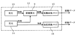
- the image capturing unit 8 and the distance calculating unit 9 constitute a main part of the distance measuring sensor unit 12 (corresponding to a detecting unit) shown in FIG.
- the image capturing unit 8 includes a light emitting unit 13 and a light receiving unit 14, and swings in a fan-shaped horizontal direction around the front direction of the vehicle.
- the light emitting unit 13 emits a laser beam in a pulse shape
- the light receiving unit 14 receives the laser beam from the light emitting unit 13 reflected in the external environment located in the detection region.
- the distance calculation unit 9 measures a time difference from when the light emitting unit 13 emits the laser light to when the light receiving unit 14 receives the light, and the distance to the external environment calculated based on the time difference corresponds to the swing angle.
- the distance image memory 15 outputs distance data in which the distance and the swing angle are associated with each other.
- the intensity of light received by the light receiver 14 is stored in the intensity image memory 16 corresponding to the swing angle.
- the intensity image memory 16 outputs image data in which the received light intensity is associated with the swing angle. This image data is referred to in order to determine the reliability of the distance data output from the distance image memory 15.
- Speed detector 10 detects the vehicle speed based on a speed signal output from a speed sensor mounted on the vehicle.
- the direction detection unit 11 detects a turning angle of the vehicle based on an angle signal output from an angle sensor mounted on the vehicle.
- the infrastructure information storage unit 4 includes a map information storage unit 17 and a traffic information storage unit 18.
- the map information storage unit 17 receives and stores map information indicating a road on which the vehicle can travel, for example, from a map information center.
- the traffic information storage unit 18 receives and stores traffic information such as road congestion information and accident information from, for example, a traffic information center. Information is used not only as countable nouns but also as countable nouns.
- the plurality of information is equivalent to the plurality of information items.
- the driving environment recognition unit 3 includes a vehicle position estimation unit 19, a travelable region recognition unit 20, an obstacle recognition unit 21, and a road sign recognition unit 22.
- the own vehicle position estimation unit 19 is a main unit to which the present disclosure is applied and will be described later.
- the travelable area recognition unit 20 calculates the distance between the stationary object, which is an external environment obtained from the image data and the distance data, and the vehicle position estimated by the vehicle position estimation unit 19 to obtain stationary object information.
- the travel lane that is the travelable area of the vehicle is recognized based on the stationary object information.
- the obstacle recognition unit 21 estimates the type of the moving body or the moving speed by detecting and tracking the moving body located around the vehicle from the image data, the distance data, and the stationary object information.
- the road sign recognition unit 22 recognizes a road sign based on information acquired by the external environment acquisition unit 2 such as image data or map data.
- the action selection unit 5 includes a lane keeping unit 23, a lane change unit 24, and an obstacle avoiding unit 25.
- the lane keeping unit 23 performs a traveling action of traveling on a traveling lane recognized by the travelable region recognizing unit 20 or traveling following the preceding vehicle when the preceding vehicle is traveling.
- the lane change unit 24 performs a danger avoidance action for the front vehicle and the rear vehicle.
- the obstacle avoidance unit 25 determines danger when an obstacle exists on the lane, and performs an avoidance action.
- the route planning unit 7 includes a global route search unit 26, which sets a destination and sets a route to the destination. That is, a route from the current position to the destination is set based on the map information stored in the map information storage unit 17 and the traffic information stored in the traffic information storage unit 18. For the route to the destination, the route cost is calculated for each grid at a predetermined interval, and the route having the minimum route cost is set.
- the vehicle control unit 6 includes an actuator driving unit 27, and performs an autonomous running operation by reflecting the result of the action selecting unit 5 on an accelerator, a brake, a steering, and the like.
- the vehicle position estimation unit 19 includes a position data memory 28 (corresponding to a storage unit), an environment map memory 29, and a verification unit 30 (also referred to as a verification machine).
- the collation unit 30 corresponds to an exercise candidate setting unit, an exercise candidate setting machine, an estimated value output unit, and an estimated value output machine. Further, the estimated value output machine is also referred to as an estimated value providing machine.
- the distance measuring sensor unit 12 is configured to detect the vehicle from an external environment located within a predetermined detection area (eg, ⁇ 60 ° to 60 ° with respect to the vehicle forward direction) with reference to the vehicle forward direction. Sensing data indicating the relative position and orientation is stored in the position data memory 28.
- the relative position of the vehicle with respect to the external environment located in the detection area can be represented by (x, y)
- the relative posture of the vehicle with respect to the external environment can be represented by the rotation angle ⁇ .
- Sensing data can be represented by (x, y, ⁇ ).
- the sensing data is also stored in the environment map memory 29 as an environment map.
- the ranging sensor unit 12 is also referred to as a ranging detector.
- the collation unit 30 is possible at the second time point that is the next detection time point after the first time point based on the environment map stored in the environment map memory 29 (that is, the sensing data at the first time point that is the previous detection time point).
- a plurality of motion candidates (x, y, ⁇ ) composed of variables indicating the position and orientation are set. And when it becomes the 2nd time point which is the next detection time point, the sensing data at the 2nd time point newly stored in the position data memory 28 and each motion candidate set to be possible at the 2nd time point And match.
- the position and orientation at the next second time point are set as motion candidates from the sensing data at the first time point, and this motion candidate is collated with the sensing data newly obtained at the second time point.
- the motion candidate is set by changing each of the three types of variables (x, y, ⁇ ) constituting the environment map.
- This motion candidate is set in a position and orientation range that is possible at the next detection time.
- the sensing data and the motion candidate at the time of this detection are collated, and the position / posture change amount from the position / posture indicated by the environment map to the position / posture indicated by the motion candidate having the maximum evaluation value is determined as a position / posture estimation value (hereinafter, estimated). Value). That is, when the estimated value is added to the environment map shown in FIG. 5, sensing data is obtained. Therefore, the estimated value can be specified by comparing the sensing data with the motion candidate.
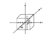
- the motion candidates when motion candidates are assigned to the three axes of the spatial coordinates, the motion candidates can be represented three-dimensionally as indicated by the circles in FIG. 6B of the comparative example.
- the motion candidates set in this way there is a motion candidate with the maximum evaluation value that matches or approximates the sensing data, and the position and orientation change amount from the position and orientation indicated by the environment map to the position and orientation indicated by the motion candidate with the maximum evaluation value Is an estimated value.
- the estimation value is specified. There is a problem that the processing time is long.
- the position and orientation at the next detection time is not estimated as in this embodiment.
- the environment map is set as an initial value.
- motion candidate x x1 (first variable) that is the maximum evaluation value. ).
- the motion candidate (x1, y2, ⁇ 3) (first variable that becomes the maximum evaluation value) that becomes the maximum evaluation value obtained as described above can be specified as the estimated value (x1, y2, ⁇ 3).
- the collation unit 30 includes a collation unit first axis 30a, a collation unit second axis 30b, and a collation unit third axis 30c. It is supposed to be.
- the first axis corresponds to x
- the second axis corresponds to y
- the third axis corresponds to ⁇ .
- the unit is distance.
- the unit is an angle ( ⁇ 60 ° to + 60 °).
- the center value for example, the third if 5
- the center value for example, 6 for the even number
- the third or fourth motion candidate is set as the estimated value. This is because the evaluation value is normally distributed around the maximum evaluation value, and the reliability of the maximum evaluation value becomes higher as the motion candidate is located at the center of the normal distribution.
- the vehicle travel locus can be specified by repeating the above-described processing, the current absolute position based on the absolute position and orientation (latitude, longitude, traveling direction) at the departure position of the vehicle.
- the posture latitude, longitude, traveling direction
- the collation unit 30 three-dimensionally sets motion candidates including a plurality of variables indicating positions and orientations that can be obtained at the next detection time based on the environmental map that is sensing data at the previous detection time, and performs sensing.
- the motion candidate that is the maximum evaluation value is estimated, and the estimated value indicating the amount of change in position and orientation from the position and orientation indicated by the environment map to the position and orientation indicated by the motion candidate having the maximum evaluation value is specified.
- the motion candidate that becomes the maximum evaluation value is estimated one-dimensionally by fixing only two types of variables and fixing only one type of variable, all the motion candidates are three-dimensionally estimated. Compared with the structure to collate, the processing time until the motion candidate used as the maximum evaluation value is estimated can be significantly reduced.
- the storage capacity of the environmental map memory 29 can be greatly reduced as compared to a configuration storing a large number of environmental maps. The time required for storing and reading can be greatly reduced.
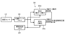
- the collation unit first axis / second axis 30d (corresponding to the division collation unit) are integrated. Is provided.
- the collation unit first axis / second axis 30d performs two-dimensional collation with the motion candidate.
- the two types of variables (x, y) indicate the position of the vehicle two-dimensionally and are related to each other, the two types of variables (x, y) are two types compared to checking for each type of variable. It can be said that the accuracy of the estimated value is higher when two-dimensional matching is performed by combining the variables (x, y).
- ⁇ 0 ° was set as an initial value, and evaluation values of two types of variables x and y were obtained.
- the number of motion candidates collated by the collation unit 1st axis / second axis 30d is 3 ⁇ 3
- the number of collation is 9
- the collation number of the collation unit 3rd axis 30c is 3 times.
- the total number of collations is 12.
- the processing time until the estimated value is specified can be reduced.
- a third embodiment will be described with reference to FIG.
- the present embodiment is characterized in that the estimated value specified by the matching unit 30 is reset in the matching unit 30 as an initial value.
- the estimated values output from the divided verification units 30a to 30c are reset to the divided verification units 30a to 30c as initial values.
- the division collation units 30a to 30c specify the estimated value by setting the environment map stored in the environment map memory 29 as the initial initial value, and the division collation units 30a to 30c corresponding to the initial value.
- the estimated value from 30c is reset as the second initial value.
- the estimated values from the division matching units 30a to 30c corresponding to the initial values are reset as the initial values, values closer to the position and orientation at the next detection time are set to the initial values. And the accuracy of the estimated values by the division verification units 30a to 30c can be improved.
- the initial value may be reset twice or more.
- the environment map is set as an initial value.
- the present embodiment is characterized in that a predicted value by a time series filter such as a Kalman filter or a particle filter is set as an initial value.
- the position and orientation at the next detection time are predicted by a time series filter. Since the time series filter has no characteristics, its description is omitted.
- the host vehicle position estimation unit 19 is provided with a time series filter unit 31 subsequent to the verification unit 30.
- the time series filter unit 31 is provided to input estimated values from the division matching units 30a to 30c, and stores the input past estimated values in time series. Since such time-series estimated values are statistical information, it is possible to accurately predict the movement of the vehicle (assuming an acceleration motion when turning) by removing noise from the statistical information. That is, as shown in FIGS. 12A, 12B, and 12C, the position and orientation at the next detection time can be accurately estimated.
- the motion candidate that has the maximum evaluation value exists on either the right side or the left side of a.
- the motion candidate indicated by b obtained by adding a predetermined value from the time series filter prediction value is evaluated.
- the exercise candidate indicated by c obtained by subtracting a predetermined value from a is evaluated.
- the evaluation value rises, it is determined that there is a possibility that the maximum evaluation value exists further on the left side, and the motion candidate indicated by d obtained by further subtracting a predetermined value is evaluated. Since the evaluation value further increases, it is determined that there is a possibility that the exercise candidate having the maximum evaluation value exists on the left side of “a”, and the exercise candidate indicated by “e” subtracted by a predetermined value is evaluated. Since the evaluation value decreases this time, it is determined that the exercise candidate having the maximum evaluation value exists in the range from the right side to c with respect to e. First, the exercise candidate indicated by f that is intermediate between c and d is evaluated. . Then, since it falls below the evaluation value of d, it is determined that the exercise candidate having the maximum evaluation value exists between d and e, and the exercise candidate indicated by g which is between d and e is evaluated.
- the search range of the motion candidates is gradually limited, and when the search range falls below a predetermined limit value or when the search is executed a specified number of times, the motion candidate that is the maximum evaluation value is searched and estimated. Output as a value.
- the accuracy of the estimated value can be increased.
- the search range of the motion candidates is limited to a predetermined range centered on the prediction value by the time series filter unit 31 and the motion candidate that becomes the maximum evaluation value is detected by binary search, the motion candidate that becomes the maximum evaluation value is selected. The processing time until the search can be further reduced.
- the present embodiment is characterized in that the number of loops for resetting the estimated value as an initial value to the division matching units 30a to 30c can be changed, and as a countermeasure therefor, resetting is performed as shown in FIG.
- a control unit 32 is provided.
- the reset control unit 32 receives the estimated value and the evaluation value from the division verification units 30a to 30c, determines whether to reset the initial value based on them, and determines to reset the initial value. In this case, the initial value is reset in the division verification units 30a to 30c.
- the exercise having the maximum evaluation value Can be confirmed as a candidate. Therefore, as shown in FIG. 17, in the division verification units 30a to 30c, when the fluctuation range of the evaluation value exceeds the predetermined value, the initial value is reset, and the fluctuation range of the evaluation value is within the predetermined value for all the axes. If this happens, the resetting of the initial value is terminated and the estimated value is finally determined.
- the loop number for resetting the initial value is fixed. In comparison, it becomes possible to respond dynamically to changes in the surrounding environment, and the accuracy of the estimated value can always be improved.
- the collation unit 30 receives position and orientation information based on the vehicle speed and rotation angle from the vehicle control ECU 33 (equivalent to an information output unit and control unit). Is set as the initial value.
- the information output unit is also referred to as an information output unit, an information providing unit, and an information providing unit.
- An exercise candidate having the maximum evaluation value in the state set as the initial value at 30c is estimated.
- the initial value can be appropriately set based on the position and orientation information from the vehicle control ECU 33, the accuracy of the estimated value can be increased.
- a seventh embodiment will be described with reference to FIGS. 19 and 20A, 20B, and 20C.
- the division verification units 30a to 30c are configured to operate in parallel.
- the division verification units 30a to 30c are configured to operate in series.
- the collation unit first axis 30 a inputs sensing data from the position data memory 28 and an environment map from the environment map memory 29.
- the collation unit second axis 30b receives the sensing data from the position data memory 28, the environment map from the environment map memory 29, and the first axis estimated value from the collation unit first axis 30a.
- the collation unit third axis 30c inputs the sensing data from the position data memory 28, the environment map from the environment map memory 29, and the second axis estimated value from the collation unit second axis 30b.
- the estimated value from the preceding stage is set as the initial value. It has become. This is because the estimated value from the previous stage is more accurate than the environmental map.
- the estimated value from the preceding stage is used as the initial value. Therefore, the accuracy of the estimated value can be improved as compared with the case where the environmental map is set as the initial value.
- the eighth embodiment will be described with reference to FIGS. 21A, 21B, and 21C.
- This embodiment is characterized in that a predicted value from the time series filter unit 31 is input to the matching unit 30 shown in the seventh embodiment instead of the environment map from the environment map memory 29.
- the estimated value from the preceding stage is set as the initial value. ing. This is because the estimated value from the previous stage side is more accurate than the predicted value by the time series filter unit 31.
- the estimated value from the preceding stage is set as the initial value.
- the accuracy of the estimated value can be increased as compared with the configuration in which the predicted value by the time series filter unit 31 is set as the initial value.
- FIGS. 22A, 22B, and 22C A ninth embodiment will be described with reference to FIGS. 22A, 22B, and 22C.
- This embodiment is characterized in that position and orientation information is input from the vehicle control ECU 33 in place of the environment map from the environment map memory 29 to the matching unit 30 shown in the seventh embodiment.
- the estimated value from the preceding stage is set as the initial value. ing. This is because the estimated value from the preceding stage is more accurate than the position and orientation information from the vehicle control ECU 33.
- the estimated value from the preceding stage is set to the initial value. Since the position and orientation information from the vehicle control ECU 33 is set as an initial value, the accuracy of the estimated value can be increased.
- a tenth embodiment will be described with reference to FIG.
- the present embodiment is characterized in that a plurality of collation units 30 in which the collation orders of the division collation units 30a to 30c operating in series are different from each other are provided and operated in parallel.
- the first verification unit 30A set so that the division verification units 30a to 30c operate in series and the division verification units 30a to 30c of the first verification unit are as follows.
- a second verification unit 30B having a different verification order is provided, and the first verification unit 30A and the second verification unit 30B are configured to operate in parallel.
- the selection unit 34 compares the estimated value from the first matching unit 30A and the estimated value from the second matching unit 30B for each variable, and specifies the estimated value with the larger evaluation value as the estimated value corresponding to the variable. .
- the first collating unit 30A and the second collating unit 30B are set so that the collating orders of the divided collating units 30a to 30c are different from each other, and are configured to operate in parallel.
- the accuracy of the estimated value can be increased as compared with the configuration in which the estimated value is specified only by the matching units 30A and 30B.
- the eleventh embodiment will be described with reference to FIG.
- the present embodiment is characterized in that the collation order of the division collation units 30a to 30c is set in accordance with the order in which the variables constituting the prediction value by the time series filter unit 31 are highly accurate.
- the predicted value by the time series filter unit 31 is relatively high in accuracy but low in robustness. Therefore, once the predicted value deviates greatly, the predicted value thereafter is greatly affected. For this reason, it is necessary to determine that the predicted value by the time series filter unit 31 is significantly different from the original predicted value.
- the position and orientation information from the vehicle control ECU 33 is compared. That is, although the accuracy of the position / orientation information from the vehicle control ECU 33 is lower than the predicted value by the time series filter unit 31, the robustness is remarkably high, so the predicted value by the time series filter unit 31 and the position / orientation from the vehicle control ECU 33 are It can be estimated that the accuracy of the predicted value by the time-series filter unit 31 has decreased as the difference from the information increases.
- the predicted value by the time series filter unit 31 and the position / orientation information from the vehicle control ECU 33 are compared for each variable, and the order of the variables is determined in ascending order of the difference (in order of accuracy).
- the collation order of the division collation units 30a to 30c is set according to the order of the variables.
- the order selection unit 35 As shown in FIG. 24, the collation order of the collation unit first axis 30a, the collation unit second axis 30b, and the collation unit third axis 30c is determined.
- the first axis estimated value is specified in a state where the second axis predicted value and the third axis predicted value with high accuracy of the predicted value by the time series filter unit 31 are set as initial values. That is, since the accuracy of the second axis predicted value and the third axis predicted value is higher than the first axis predicted value, the collation unit first axis 30a uses the second axis predicted value and the third axis predicted value as initial values. Set the value.
- the second axis estimation value is specified in a state where the predicted value of the third axis from the time series filter unit 31 and the first axis estimation value from the collation unit first axis 30a are set as initial values. To do.
- the first axis estimated value from the collation unit first axis 30a and the second axis estimated value from the collation unit second axis 30b are set as initial values. Is identified.
- the collation order of the division collation units 30a to 30c is set in accordance with the order in which the accuracy of the variables constituting the prediction value by the time series filter unit 31 is high, the accuracy of the estimated value Can be increased.
- this embodiment is characterized in that the collation order of the division collation units 30a to 30c can be changed, and as a countermeasure therefor, an order control unit 36 is provided as shown in FIG.
- the order control unit 36 receives the evaluation value and the estimated value from the division collation units 30a to 30c, determines the collation order of the division collation units 30a to 30c based on them, and sets the collation order to the division collation units 30a to 30c. 30c.
- the method for determining the collation order will be described.
- the rising or falling inclination angle of the evaluation value distribution is different for each axis.
- the smaller the inclination angle the more easily the maximum evaluation value is affected by noise, so it can be said that the accuracy of the motion candidate that is the maximum evaluation value is low.
- the accuracy of the motion candidate that is the maximum evaluation value is the lowest. For this reason, when the motion candidate having the maximum evaluation value is specified from the x axis, the influence on the subsequent stage becomes large. Therefore, the collation order is set in the order of the ⁇ axis and the x axis in order from the y axis having the maximum inclination angle. It is desirable to set.
- the inclination angle is determined based on the inclination of the hypotenuse of a right triangle having the maximum evaluation value and a predetermined motion candidate as a vertex.
- the height dimension of the right triangle may be set to 1/2 of the maximum evaluation value, for example, but may be set to 1/3, 2/3, or the like.
- the collation order of the division collation units 30a to 30c is set so that the slope of the hypotenuse becomes larger.
- the collation order of the division collation units 30a to 30c is set in descending order of the rising or falling inclination angle of the evaluation value distribution, the division collation units 30a to 30c on the subsequent stage side are set.
- a highly accurate initial value can be set, and the accuracy of the estimated value can always be improved.
- the sensing data, the environment map, and the motion candidate are configured with three types of variables, but may be configured with four or more types of variables.
- the number of variables is N
- the variable to be fixed is in the range of 1 to N-1.
- the current absolute position and orientation (latitude, longitude, traveling direction) may be corrected based on the position and orientation information.
Landscapes
- Engineering & Computer Science (AREA)
- Radar, Positioning & Navigation (AREA)
- Remote Sensing (AREA)
- Physics & Mathematics (AREA)
- General Physics & Mathematics (AREA)
- Automation & Control Theory (AREA)
- Aviation & Aerospace Engineering (AREA)
- Traffic Control Systems (AREA)
Abstract
移動体の位置姿勢推定装置に於いて、前回の第1検出時点でのセンシングデータである環境地図に基づいて次の第2検出時点で可能となる位置姿勢を示す複数の運動候補を設定する。照合部(30)は、第2検出時点でのセンシングデータと運動候補のそれぞれとを照合することにより最大評価値となる運動候補を推定し、環境地図が示す位置姿勢から最大評価値の運動候補が示す位置姿勢に至る位置姿勢変化量を特定する。この場合に、照合部を構成する複数の分割照合部(30a~30c)は、互いに異なる第1変数を変化させる一方、他の変数である第2変数は固定しておき、最大評価値となる運動候補を推定する。
Description
本出願は、2015年6月12日に出願された日本出願番号2015-119298号と、2015年12月24日に出願された日本出願番号2015-251499号に基づくもので、ここにその記載内容を援用する。
本開示は、環境地図に基づいて設定した運動候補とセンシングデータとを照合することにより移動体の現在の位置姿勢を推測する移動体の位置姿勢推定装置及び移動体の自律走行システムに関する。
車両やロボット等の移動体の現在の位置姿勢を推定する際には、一般的には、前回の検出時点からの移動体の位置姿勢変化量として位置(x,y)と姿勢θの3種類の変数(x,y,θ)を特定する必要がある。この3種類の変数の変化量を求めるには、外部環境に対する移動体の相対的な位置姿勢を例えば測距センサにより検出し、測距センサから取得したセンシングデータと前回の検出時点でのセンシングデータである環境地図との照合を実施する。
照合方法としては、環境地図に基づいて次の検出時点での移動体の位置姿勢を示す運動候補を設定し、その運動候補とセンシングデータとを照合することで行われる。運動候補は次の検出時点で可能となる位置姿勢であり、環境地図を所定の(x,y)だけ並行移動させると共に所定のθだけ回転させて設定する。このような照合を運動候補の数だけ実施し、照合精度を示す評価値が最大となる運動候補を推定することで現在の位置姿勢を特定する。
上記のような照合方法により最大評価値となる運動候補を推定する場合、運動候補が3種類の変数(x,y,θ)から構成されるため、環境地図に基づいて設定する運動候補の数が膨大となり、照合の処理量が大きいという課題がある。
このような課題に対して、特許文献1では、環境地図を作成する対策と位置姿勢を推定する対策とを分離し、位置姿勢を推定する対策での処理量を減らす方法を提案している。また、環境地図の作成では、センシングデータに基づいて有効画素のみ抽出しているため、位置姿勢を推定する対策では、無効画素の判定を省略することで照合の処理量を低減している。
しかしながら、特許文献1では、全ての運動候補と照合する必要があるため、照合の処理時間が膨大になる欠点がある。また、処理量に関しても、環境地図を作成する処理では、無効画素を判定する処理が存在するため、それらのデータ処理を含めた全体の処理量を大きく低減することはできない。さらに、環境地図の作成を外部のコンピュータで実施して通信により取得する構成なので、外部のコンピュータとの通信時間が発生し、この点でも処理時間を要する。
本開示の目的は、環境地図に基づいて設定した運動候補とセンシングデータとを照合することにより移動体の現在の位置姿勢を推測する場合に、移動体の位置姿勢を推定するまでの処理時間を大幅に低減することができる移動体の位置姿勢推定装置及び移動体の自律走行システムを提供することにある。
本開示の一つの観点によれば、移動体の位置姿勢推定装置は、検出部、記憶部、運動候補設定部、照合部、推定値出力部、とを備えるように構成される。検出部は、所定の連続する検出時点の各時点で外部環境に対する移動体の相対的な位置姿勢を示す複数の変数から構成されるセンシングデータを検出する。記憶部は、前回の検出時点である第1時点のセンシングデータを複数の変数から構成される第1時点に対応する環境地図として記憶する。運動候補設定部は、第1時点に対応する環境地図に基づいて、第1時点の次の検出の時点である第2時点で移動体が可能となる位置姿勢を示す、各々が複数の変数から構成される複数の運動候補を設定する。照合部は、第2時点でのセンシングデータと運動候補のそれぞれとを照合し、照合精度を示す評価値が最大である最大評価値となる最大評価運動候補を推定する。推定値出力部は、第1時点に対応する環境地図が示す位置姿勢から最大評価運動候補が示す位置姿勢に至る変化量を位置姿勢推定値として出力する。さらに、照合部は、複数の分割照合部から構成される。分割照合部の各々は、運動候補を構成する複数の変数の内、少なくとも一つを第1変数として選択し、その他全てを第2変数として選択し、ここで、分割照合部の各々が選択する第1変数は互いに異なるように選択されている。分割照合部の各々は、第2変数として所定の初期値を固定値として設定し変化させない状態で第1変数を変化させて評価値を求めることにより最大評価値となる第1変数を推定する。推定値出力部は、分割照合部がそれぞれ推定した最大評価値となる第1変数を位置姿勢推定値として出力する。
上記の構成によれば、位置姿勢推定値を累積して合算することで車両の走行軌跡を特定することができる。
本開示についての上記目的およびその他の目的、特徴や利点は、添付の図面を参照しながら下記の詳細な記述により、より明確になる。
第1実施形態における自律走行システムを示す機能ブロック図
測距センサ部を示す機能ブロック図
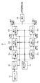
照合部の構成を示す機能ブロック図
外部環境に対する測距センサの位置姿勢を示す図
センシングデータと環境地図との関係を示す図
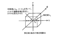
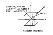
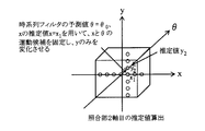
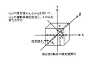
最大評価値となる運動候補を推定する第1実施形態における手順を示す図
最大評価値となる運動候補を推定する手順を示す比較例を示す図
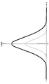
x1を中心とする正規分布を示す図
センシングデータと環境地図との照合手順を示す図
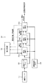
第2実施形態における照合部の構成を示す機能ブロック図
第3実施形態における照合部の構成を示す機能ブロック図
第4実施形態における照合部の構成を示す機能ブロック図
最大評価値となる運動候補を推定する手順を示す図(その1)
最大評価値となる運動候補を推定する手順を示す図(その2)
最大評価値となる運動候補を推定する手順を示す図(その3)
バイナリサーチの手順を示す図
第5実施形態における照合部の構成を示す機能ブロック図
運動候補と評価値との関係を示す図
運動候補と評価値との関係を示す図
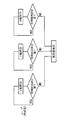
推定値を確定する方法を示すフローチャート
第6実施形態における照合部の構成を示す機能ブロック図
第7実施形態における照合部の構成を示す機能ブロック図
最大評価値となる運動候補を推定する手順を示す図(その1)
最大評価値となる運動候補を推定する手順を示す図(その2)
最大評価値となる運動候補を推定する手順を示す図(その3)
第8実施形態における最大評価値となる運動候補を推定する手順を示す図(その1)
第8実施形態における最大評価値となる運動候補を推定する手順を示す図(その2)
第8実施形態における最大評価値となる運動候補を推定する手順を示す図(その3)
第9実施形態における最大評価値となる運動候補を推定する手順を示す図(その1)
第9実施形態における最大評価値となる運動候補を推定する手順を示す図(その2)
第9実施形態における最大評価値となる運動候補を推定する手順を示す図(その3)
第10実施形態における照合部の構成を示す機能ブロック図
第11実施形態における照合部の構成を示す機能ブロック図
第12実施形態における照合部の構成を示す機能ブロック図
運動候補と評価値との関係を示す図
評価値分布の立上りまたは立下りの傾斜角度を求めるための方法を示す図
(第1実施形態)
第1実施形態について図1から図8を参照して説明する。
第1実施形態について図1から図8を参照して説明する。
図1に示すように、車両には自律走行システム1が搭載されている。この車両は、搭載車、当該車、あるいは自車(Host Vehicle)とも言及される。自律走行システム1は、位置姿勢推定装置を構成する外部環境取得部2、走行環境認識部3及びインフラ情報保存部4と、自律走行装置を構成する行動選択部5、車両制御部6及び経路計画部7とから構成されている。尚、本開示において、自律走行システム1を構成する上記の各部は、後述するように、さらに分割されて構成される部、あるいは組合わさって構成される部として提供される。これらの部の各々は、(i)ハードウエアユニット(例えば、CPU,RAM,ROM等を含むコンピュータ)と組み合わさったソフトウエアの部として、あるいは(ii)ハードウエア(例えば、集積回路、配線論理回路)の部として、関連する装置の機能を含みあるいは含まずに実現できる。さらに、ハードウエアの部は、マイクロコンピュータの内部に含まれることもできる。
外部環境取得部2は、画像撮像部8、距離算出部9、速度検出部10及び方向検出部11から構成されている。
画像撮像部8及び距離算出部9は、図2に示す測距センサ部12(検出部に相当)の要部を構成するものである。画像撮像部8は発光部13及び受光部14から構成されており、車両の前方方向を中心として扇状の水平方向に首振り運動するようになっている。発光部13はレーザ光をパルス状に照射し、受光部14は、検出領域に位置する外部環境で反射した発光部13からのレーザ光を受光する。距離算出部9は、発光部13がレーザ光を照射してから受光部14が受光するまでの時間差を計測し、その時間差に基づいて算出した外部環境までの距離を首振り角度に対応して距離画像メモリ15に記憶する。距離画像メモリ15は、距離と首振り角度とを対応付けた距離データを出力する。受光部14による受光強度は、首振り角度に対応して強度画像メモリ16に記憶される。強度画像メモリ16は、受光強度と首振り角度とを対応付けた画像データを出力する。この画像データは、距離画像メモリ15から出力される距離データの信頼性を判定するために参照される。
速度検出部10は、車両に搭載された速度センサから出力される速度信号に基づいて車両速度を検出する。方向検出部11は、車両に搭載された角度センサから出力される角度信号に基づいて車両の旋回角度を検出する。
インフラ情報保存部4は、地図情報保存部17及び交通情報保存部18から構成されている。地図情報保存部17は、車両が走行可能な道路を示す地図情報を例えば地図情報センタから受信して保存する。交通情報保存部18は、道路の混雑情報や事故情報等の交通情報を例えば交通情報センタから受信して保存する。尚、情報は、不可算名詞のみならず、可算名詞としても使用される。複数の情報は、複数の情報項目と同等である。
走行環境認識部3は、自車位置推定部19、走行可能領域認識部20、障害物認識部21及び道路標識認識部22から構成されている。自車位置推定部19は、本開示が適用される主要部であり、後述する。走行可能領域認識部20は、画像データや距離データから得られた外部環境である静止物と自車位置推定部19が推定した自車位置との間の距離を演算することで静止物情報を求め、その静止物情報に基づいて車両の走行可能領域である走行レーンを認識する。障害物認識部21は、画像データや距離データや静止物情報から車両の周囲に位置する移動体を検出して追跡することにより、移動体の種別を推定したり移動速度を推定したりする。
道路標識認識部22は、画像データや地図データのような外部環境取得部2が取得した情報に基づいて道路標識を認識する。
行動選択部5は、レーンキープ部23、レーンチェンジ部24及び障害物回避部25から構成されている。レーンキープ部23は、走行可能領域認識部20が認識した走行レーンを走行したり、前方車両が走行している場合には当該前方車両に追随して走行したりする走行行動を実施する。レーンチェンジ部24は、前方車両や後方車両への危険回避行動を実施する。障害物回避部25は、レーン上に障害物が存在する場合等に危険を判断し、回避行動を実施する。
経路計画部7はグローバル経路探索部26からなり、目的地を設定すると共に、当該目的地に至る経路を設定する。つまり、地図情報保存部17に保存されている地図情報と、交通情報保存部18に保存されている交通情報とに基づいて、現在位置から目的地に至るまでの経路を設定する。目的地に至る経路は、所定間隔毎のグリッド毎に経路コストを計算し、経路コストの合計が最小となる経路を設定する。
車両制御部6はアクチュエータ駆動部27からなり、行動選択部5による結果を、アクセル、ブレーキ、ステアリング等に反映することで自律走行動作を実施する。
さて、本開示は、走行環境認識部3を構成する自車位置推定部19に関することから、以下、自車位置推定部19について詳述する。
自車位置推定部19は、図3に示すように、位置データメモリ28(記憶部に相当)、環境地図メモリ29及び照合部30(照合機とも言及される)から構成されている。照合部30は運動候補設定部、運動候補設定機、推定値出力部、推定値出力機に相当する。更に、推定値出力機は、推定値提供機とも言及される。測距センサ部12は、図4に示すように、車両の前方方向を基準として所定の検出領域(車両の前方方向に対して例えば-60°~60°)内に位置する外部環境に対する車両の相対的な位置姿勢を示すセンシングデータを位置データメモリ28に記憶する。この場合、検出領域に位置する外部環境に対する車両の相対的な位置は(x,y)で示すことができる一方、外部環境に対する車両の相対的な姿勢は回転角θで表すことができることから、センシングデータは(x,y,θ)で表すことができる。このように位置データメモリ28にセンシングデータが記憶される場合は、当該センシングデータは環境地図として環境地図メモリ29にも記憶される。測距センサ部12は、測距ディテクタとも言及される。
照合部30は、環境地図メモリ29に記憶された環境地図(即ち、前回の検出時点である第1時点のセンシングデータ)に基づいて第1時点の次の検出時点である第2時点において可能となる位置姿勢を示す変数から構成される複数の運動候補(x,y,θ)を設定する。そして、次の検出時点である第2時点となった場合は、位置データメモリ28に新たに記憶される第2時点でのセンシングデータと、第2時点において可能となると設定されたそれぞれの運動候補とを照合する。言い換えると、第1時点のセンシングデータから、次の第2時点での位置姿勢を運動候補として設定し、この運動候補を、第2時点で新たに得られたセンシングデータと照合することとなる。
照合部30が運動候補を設定するには、環境地図を構成する3種類の変数(x,y,θ)をそれぞれ変化させることにより運動候補を設定する。この運動候補は、次の検出時点で可能となる位置姿勢範囲で設定される。そして、今回の検出時点でのセンシングデータと運動候補とを照合し、環境地図が示す位置姿勢から最大評価値の運動候補が示す位置姿勢に至る位置姿勢変化量を位置姿勢推定値(以下、推定値)として特定する。つまり、図5に示す環境地図に推定値を合算するとセンシングデータとなることから、センシングデータと運動候補とを照合することで推定値を特定することが可能となる。
さて、運動候補を空間座標の3軸に割り当てると、比較例の図6Bに丸印で示すように、運動候補を立体的に表すことができる。このように設定した運動候補の中にセンシングデータと一致または近似する最大評価値の運動候補が存在し、環境地図が示す位置姿勢から最大評価値の運動候補が示す位置姿勢に至る位置姿勢変化量が推定値ということになる。
ところで、従来手法の推定値の推測方法では、センシングデータと、比較例の図6Bに丸印で示す全ての運動候補とを3次元的に照合していたことから、推定値を特定するまでの処理時間が長いという課題がある。
また、次の検出時点での位置姿勢を推測し、推測した位置姿勢を中心として運動候補と照合するのが望ましいものの、本実施形態のように次の検出時点での位置姿勢を推定しない構成の場合は、環境地図を初期値として設定することになる。
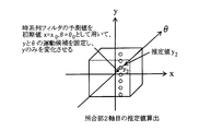
即ち、運動候補を構成する3種類の変数の内、x以外の2種類の変数y,θに関して、初期値としてy0=0、θ0=0°と設定してyとθを固定すると、変数はxのみとなる。x=x1が最大評価値と仮定すると、xの運動候補は、xを横軸、評価値を縦軸で示すと、図7に実線で示すように、x=x1の評価値が最大となり、x=x1から離間するにしたがって評価値が減少する正規分布を示すようになる。
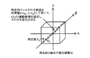
ここで、運動候補の探索範囲に位置するように横軸に平行な第2横軸を想定すると、第2横軸上の運動候補もx=x1が最大評価値となる正規分布を示すようになる。これは、x=x1を中心として評価値が正規分布を示していることから、第2横軸が評価値の正規分布領域を通過する場合には、図7に点線で示すように、第2横軸上の運動候補もx=x1が最大評価値となる正規分布を示すようになる。従って、初期値としてy=y0、θ=θ0(第2変数)を設定することにより、本実施形態においては、図6Aに示すように、最大評価値となる運動候補x=x1(第1変数)を求めることができる。同様にして、初期値としてx=x0、θ=θ0(第2変数)を設定することにより、最大評価値となる運動候補y=y2(第1変数)を求めることができる。さらに、初期値として変数x=x0,y=y0(第2変数)を設定することにより、最大評価値となる運動候補としてθ=θ3(第1変数)を求めることができる。そして、以上のようにしてそれぞれ求めた最大評価値となる運動候補(x1,y2,θ3)(最大評価値となる第1変数)を推定値(x1,y2,θ3)として特定することができる。
このような推定方法を実現するために、照合部30は、照合部1軸目30a、照合部2軸目30b及び照合部3軸目30cから構成されており、1次元的に運動候補と照合するようになっている。1軸目はxに対応し、2軸目はyに対応し、3軸目はθに対応する。x,yに関しては、その単位は距離となる。θに関しては、その単位は角度(-60°~+60°)となる。
説明の簡略化のために、図8に示すように、各軸の運動候補が3個ずつ設定されているものとして説明する。
照合部1軸目30aは、初期値としてy=0、θ=0°を設定することで、照合対象となる運動候補をxのみを変数とする1次元として評価値を判定する。図8に示す例では、x=1、x=0、x=-1の評価値を判定している。この場合、x=0のときに最大評価値となることから、1軸上で最大評価値となる運動候補はx=0であると推定する。
照合部2軸目30bは、x=0、θ=0°を設定することで、照合対象となる運動候補をyのみを変数とする1次元として評価値を判定する。図8に示す例では、y=1、y=0、y=-1の評価値を求めている。この場合、y=0のときに最大評価値となることから、2軸上で最大評価値となる運動候補はy=0であると推定する。
照合部3軸目30cは、x=0、y=0を設定することで、照合対象となる運動候補をzのみを変数とする1次元として評価値を判定する。図8に示す例では、θ=90°、θ=0°、θ=-90°の評価値を判定している。この場合、θ=-90°のときに最大評価値となることから、3軸上で最大評価値となる運動候補はθ=-90°であると推定する。
以上のようにして、各照合部1~3軸目(以下、分割照合部あるいは分割照合機とも言及される)30a~30cにより、最大評価値となる運動候補としてx=0、y=0、θ=-90°を推定したことから、位置姿勢変化量を示す推定値として(0,0,-90°)を特定する。
要するに、各軸に対応した運動候補が図8に示すような場合、従来の手法では各軸の全ての運動候補を3次元的に組み合わせた数である27(=3×3×3)回だけセンシングデータと運動候補とを照合する必要があったが、本実施形態では、1次元的に組み合わせた9(=3+3+3)回で済み、センシングデータと運動候補との照合回数を減少させて処理時間を大幅に低減することができる。この場合、従来の手法では、運動候補の数が照合回数となることから、運動候補が多くなる程、それだけ処理時間の低減効果が大きくなると言える。
尚、最大評価値となる運動候補が複数存在した場合、その数が奇数個の場合は中央の値(例えば5個の場合は3番目)、偶数個の場合は中央側の値(例えば6個の場合は3番目か4番目)の運動候補を推定値とする。これは、評価値は最大評価値を中心として正規分布していることから、正規分布の中央に位置する運動候補となる程、最大評価値の信頼性が高くなるからである。
そして、上述のような処理を繰り返すことにより車両の走行軌跡を特定することができるので、車両の出発位置における絶対的な位置姿勢(緯度、経度、進行方位)に基づいて現在の絶対的な位置姿勢(緯度、経度、進行方位)を特定することができる。
このような実施形態によれば、次のような効果を奏することができる。
照合部30は、前回の検出時点でのセンシングデータである環境地図に基づいて次の検出時点で可能となる位置姿勢を示す複数の変数から構成される運動候補を3次元的に設定し、センシングデータと運動候補とを照合することにより最大評価値となる運動候補を推定し、環境地図が示す位置姿勢から最大評価値の運動候補が示す位置姿勢に至る位置姿勢変化量を示す推定値を特定する場合に、2種類の変数を固定して1種類の変数のみを変化させることで最大評価値となる運動候補を1次元的に推定するようにしたので、全ての運動候補と3次元的に照合する構成に比較して、最大評価値となる運動候補を推定するまでの処理時間を大幅に低減することができる。
前回の検出時点でのセンシングデータである環境地図のみを記憶すれば良いことから、多数の環境地図を記憶する構成に比較して、環境地図メモリ29の記憶容量を大幅に削減できる共に環境地図を記憶したり読出したりするのに要する時間を大幅に低減することができる。
(第2実施形態)
第2実施形態について図9を参照して説明する。第1実施形態では、分割照合部30a~30cにおいて、2種類の変数を固定し、1種類の変数の評価値を求めたが、本実施形態では、1種類の変数を固定し、2種類の変数の評価値を求めることを特徴とする。
第2実施形態について図9を参照して説明する。第1実施形態では、分割照合部30a~30cにおいて、2種類の変数を固定し、1種類の変数の評価値を求めたが、本実施形態では、1種類の変数を固定し、2種類の変数の評価値を求めることを特徴とする。
図9に示すように、第1実施形態の照合部1軸目30a、照合部2軸目30bに代えて、それらを統合した照合部1軸目・2軸目30d(分割照合部に相当)が設けられている。照合部1軸目・2軸目30dは、運動候補との照合を2次元的に行うものである。
即ち、2種類の変数(x,y)は車両の位置を2次元的に示すものであり、互いに関連するものであることから、1種類の変数毎に照合するのに比較して、2種類の変数(x,y)を組み合わせて2次元的に照合する方が推定値の精度が高くなると言える。
そこで、初期値としてθ=0°と設定し、x,yの2種類の変数の評価値を求めるようにした。この場合、照合部1軸目・2軸目30dが照合する運動候補は3×3の9個であることから、照合回数は9回となり、照合部3軸目30cの照合回数の3回を加えると全体の照合回数は12回となる。これにより、第1実施形態の照合回数よりも増加することになるものの、従来の照合回数に対しては低減することができる。
このような実施形態によれば、運動候補を構成する変数の内、複数の変数の組み合せを考慮しないと推定値の精度が低下するような場合に、推定精度が低減することを抑制しながら、第1実施形態と同様に、推定値を特定するまでの処理時間を低減することができる。
(第3実施形態)
第3実施形態について図10を参照して説明する。本実施形態は、照合部30で特定した推定値を初期値として照合部30に再設定することを特徴とする。
第3実施形態について図10を参照して説明する。本実施形態は、照合部30で特定した推定値を初期値として照合部30に再設定することを特徴とする。
初期値としては、次の検出時点での位置姿勢に極力近い値を設定することが重要である。つまり、初期値が次の検出時点での位置姿勢に近い程、正規分布の精度が高くなり、特定した推定値(x1,y2,θ3)の精度が高くなるからである。
そこで、図10に示すように、分割照合部30a~30cから出力される推定値を初期値として分割照合部30a~30c再設定するようにした。この場合、分割照合部30a~30cは、環境地図メモリ29に記憶されている環境地図を1回目の初期値として設定することで推定値を特定すると共に、初期値に対応する分割照合部30a~30cからの推定値を2回目の初期値として再設定するようになっている。
このような実施形態によれば、初期値に対応する分割照合部30a~30cからの推定値を初期値として再設定するようにしたので、次の検出時点での位置姿勢により近い値を初期値として設定でき、分割照合部30a~30cによる推定値の精度を高めることができる。尚、初期値の再設定を2回以上行うようにしても良い。
(第4実施形態)
第4実施形態について図11から図13を参照して説明する。第1実施形態では、初期値として環境地図を設定したが、本実施形態では、カルマンフィルタ、パーティクルフィルタ等の時系列フィルタによる予測値を初期値として設定することを特徴とする。
第4実施形態について図11から図13を参照して説明する。第1実施形態では、初期値として環境地図を設定したが、本実施形態では、カルマンフィルタ、パーティクルフィルタ等の時系列フィルタによる予測値を初期値として設定することを特徴とする。
上述したように、初期値としては、次の検出時点での位置姿勢に極力近い値を設定することが重要である。
そこで、本実施形態では、次の検出時点での位置姿勢を時系列フィルタで予測するようにした。尚、時系列フィルタについては特徴がないことから、その説明は省略する。
図11に示すように、自車位置推定部19には、照合部30の後段に時系列フィルタ部31が設けられている。この時系列フィルタ部31は、分割照合部30a~30cからの推定値を入力するように設けられており、入力した過去の推定値を時系列に記憶している。このような時系列的な推定値は統計情報であることから、その統計情報からノイズを除去することで車両の動きを精度良く予測(旋回時は加速度運動を想定)可能となる。つまり、図12A,図12B,図12Cに示すように、次の検出時点での位置姿勢を精度良く推定することができる。
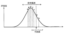
ここで、図13に示すように、運動候補の探索範囲は、時系列フィルタ部31による予測値を中心とした所定範囲に制限することが有効であることから、車両の加減速の限界値である9.8m/s2若しくは走行結果から求めた最大の変化幅に設定する。このように探索範囲を制限することにより、最大評価値となる運動候補を探索するまでの処理時間を低減することができる。
さらに、最大評価値となる運動候補を求める場合、センシングデータを探索範囲の全ての運動候補と照合する必要はなく、最大評価値となる運動候補をバイナリサーチにより検出することで処理時間の一層の低減化を図ることができる。
具体的には、時系列フィルタ予測値が図13に示すaであった場合、aの右側か左側のいずれかに最大評価値となる運動候補が存在することになる。aの右側に最大評価値となる運動候補が存在すると仮定し、時系列フィルタ予測値から所定値だけ加算したbで示す運動候補を評価する。この場合、評価値が減少することから、最大評価値となる運動候補はaの右側には存在せず、左側に存在すると判断し、aから所定値だけ減算したcで示す運動候補を評価する。この場合、評価値が上昇することから、最大評価値はさらに左側に存在する可能性があると判断し、さらに所定値だけ減算したdで示す運動候補を評価する。評価値がさらに上昇することから、最大評価値となる運動候補はaの左側に存在する可能性があると判断し、さらに所定値だけ減算したeで示す運動候補を評価する。今度は評価値が減少することから、最大評価値となる運動候補はeよりも右側からcまでの範囲に存在すると判断し、まず、cとdの中間となるfで示す運動候補を評価する。すると、dの評価値よりも低下することから、最大評価値となる運動候補はdとeとの中間に存在すると判断し、dとeとの中間となるgで示す運動候補を評価する。
以上のようにして運動候補の探索範囲を徐々に制限し、探索範囲が所定の限界値以下となった場合、若しくは探索を指定回数実行した場合に最大評価値となる運動候補を探索して推定値として出力する。
このような実施形態によれば、時系列フィルタ部31による予測値を初期値として設定するようにしたので、推定値の精度を高めることができる。
運動候補の探索範囲を時系列フィルタ部31による予測値を中心とした所定範囲に制限すると共に最大評価値となる運動候補をバイナリサーチにより検出するようにしたので、最大評価値となる運動候補を探索するまでの処理時間を一層低減することができる。
(第5実施形態)
第5実施形態について図14~17を参照して説明する。実際の走行シーンでは、アクセル制御やステアリング操作により自車の動きが変動し、周辺環境にある静止物の配置も動的に変動するため、その変動に対応するのが望ましい。しかし、上記の第3及び第4実施形態では、分割照合部30a~30cに対して推定値を初期値として再設定するループ回数は固定されており、変動に対して適切に対応できないことが予測される。
第5実施形態について図14~17を参照して説明する。実際の走行シーンでは、アクセル制御やステアリング操作により自車の動きが変動し、周辺環境にある静止物の配置も動的に変動するため、その変動に対応するのが望ましい。しかし、上記の第3及び第4実施形態では、分割照合部30a~30cに対して推定値を初期値として再設定するループ回数は固定されており、変動に対して適切に対応できないことが予測される。
そこで、本実施形態は、分割照合部30a~30cに対して推定値を初期値として再設定するループ回数を変動可能としたことを特徴とし、そのための対策として、図14に示すように再設定制御部32を設けた。この再設定制御部32は、分割照合部30a~30cから推定値及びその評価値を入力し、それらに基づいて初期値を再設定するか否かを判断し、初期値を再設定すると判断した場合は、初期値を分割照合部30a~30cに再設定するものである。
初期値を再設定するか否かの判断方法について説明する。図15に示すような運動候補に対する評価値分布が得られた場合、軸毎に収束回数は異なるものの、初期値の再設定を繰り返すことにより図中に丸数字で示す順番で真値に向かって収束するものと考えられる。
ここで、図16に示すように、初期値を再設定した結果、得られた評価値の変動幅(図16中に示すΔ評価値)が所定値内となれば、最大評価値となる運動候補であることを確定することができる。そこで、図17に示すように、分割照合部30a~30cにおいて、評価値の変動幅が所定値を上回る場合は初期値を再設定し、全ての軸において評価値の変動幅が所定値内となった場合は、初期値の再設定を終了して推定値を最終的に確定する。
このような実施形態によれば、最大評価値となる運動候補を特定するまで初期値を再設定するループ回数を変動可能としたので、初期値の再設定するループ回数が固定している構成に比較して、周囲環境の変動に対して動的に対応可能となり、推定値の精度を常に高めることができる。
(第6実施形態)
第6実施形態について図18を参照して説明する。本実施形態は、車両制御ECU33からの位置姿勢情報に基づいて初期値を設定することを特徴とする。
第6実施形態について図18を参照して説明する。本実施形態は、車両制御ECU33からの位置姿勢情報に基づいて初期値を設定することを特徴とする。
図18に示すように、照合部30は、車両制御ECU33(情報出力部、制御部に相当)から車両速度及び回転角に基づく位置姿勢情報が入力するようになっており、入力した位置姿勢情報を初期値として設定するようになっている。尚、情報出力部は、情報出力機、情報提供部、情報提供機とも言及される。
即ち、照合部30は、車両制御ECU33からの位置姿勢情報に基づいて次の検出時点でのx方向位置x=x0、y方向位置y=y0、回転角θ=θ0を、分割照合部30a~30cに初期値として設定した状態で最大評価値となる運動候補を推測する。
このような実施形態によれば、車両制御ECU33からの位置姿勢情報に基づいて初期値を適切に設定することができるので、推定値の精度を高めることができる。
(第7実施形態)
第7実施形態について図19及び図20A,図20B、図20Cを参照して説明する。第1実施形態では、分割照合部30a~30cを並列動作するように構成したが、本実施形態では、分割照合部30a~30cを直列動作するように構成したことを特徴とする。
第7実施形態について図19及び図20A,図20B、図20Cを参照して説明する。第1実施形態では、分割照合部30a~30cを並列動作するように構成したが、本実施形態では、分割照合部30a~30cを直列動作するように構成したことを特徴とする。
図19に示すように、照合部1軸目30aは、位置データメモリ28からのセンシングデータと環境地図メモリ29からの環境地図とを入力する。照合部2軸目30bは、位置データメモリ28からのセンシングデータと環境地図メモリ29からの環境地図と照合部1軸目30aからの1軸目推定値とを入力する。照合部3軸目30cは、位置データメモリ28からのセンシングデータと環境地図メモリ29からの環境地図と照合部2軸目30bからの2軸目推定値とを入力する。この場合、分割照合部30a~30cにおいて、環境地図メモリ29からの環境地図と前段側からの推定値との両方が入力する場合には、初期値として前段側からの推定値を設定するようになっている。これは、前段側からの推定値の方が環境地図よりも精度が高いからである。
図20Aに示すように、照合部1軸目30aは、初期値として環境地図によるy=y0とθ=θ0とを設定してyとθの運動候補を固定し、xのみを変化させて最大評価値となる運動候補としてx=x1を推定する。
次に図20Bに示すように、照合部2軸目30bは、初期値として環境地図によるθ=θ0と照合部1軸目30aからの1軸目推定値x1とを設定してxとθの運動候補を固定し、yのみを変化させて最大評価値となる運動候補としてy=y2を推定する。
最後に図20Cに示すように、照合部3軸目30cは、初期値として照合部1軸目30aからの1軸目推定値x=x1と照合部2軸目30bからの2軸目推定値y=y2とを設定してxとyの運動候補を固定し、θのみを変化させて最大評価値となる運動候補としてθ=θ3を推定する。
このような実施形態によれば、分割照合部30a~30cにおいて、環境地図メモリ29からの環境地図と前段側からの推定値との両方が入力する場合は、前段側からの推定値を初期値として設定するようにしたので、環境地図を初期値として設定する場合に比較して、推定値の精度を高めることができる。
(第8実施形態)
第8実施形態について図21A,図21B,図21Cを参照して説明する。本実施形態は、第7実施形態で示す照合部30に対して、環境地図メモリ29からの環境地図に代えて時系列フィルタ部31による予測値が入力することを特徴とする。この場合、分割照合部30a~30cにおいて、時系列フィルタ部31による予測値と前段側からの推定値との両方が入力する場合は、初期値として前段側からの推定値を設定するようになっている。これは、前段側からの推定値の方が時系列フィルタ部31による予測値よりも精度が高いからである。
第8実施形態について図21A,図21B,図21Cを参照して説明する。本実施形態は、第7実施形態で示す照合部30に対して、環境地図メモリ29からの環境地図に代えて時系列フィルタ部31による予測値が入力することを特徴とする。この場合、分割照合部30a~30cにおいて、時系列フィルタ部31による予測値と前段側からの推定値との両方が入力する場合は、初期値として前段側からの推定値を設定するようになっている。これは、前段側からの推定値の方が時系列フィルタ部31による予測値よりも精度が高いからである。
図21Aに示すように、照合部1軸目30aは、初期値として時系列フィルタ部31による予測値y=y0、θ=θ0を設定してyとθの運動候補を固定し、xのみを変化させて最大評価値となる運動候補としてx=x1を推定する。
次に図21Bに示すように、照合部2軸目30bは、初期値として時系列フィルタ部31による予測値θ=θ0と照合部1軸目30aからの1軸目推定値x=x1とを設定してxとθの運動候補を固定し、yのみを変化させて最大評価値となる運動候補としてy=y2を推定する。
最後に図21Cに示すように、照合部3軸目30cは、初期値として照合部1軸目30aからの1軸目推定値x=x1と照合部2軸目30bからの2軸目推定値y=y2を設定してxとyの運動候補を固定し、θのみを変化させて最大評価値となる運動候補としてθ=θ3を推定する。
このような実施形態によれば、分割照合部30a~30cにおいて、時系列フィルタ部31による予測値と前段側からの推定値とが入力する場合は、前段側からの推定値を初期値として設定するようにしたので、時系列フィルタ部31による予測値を初期値として設定する構成に比較して、推定値の精度を高めることができる。
(第9実施形態)
第9実施形態について図22A、図22B、図22Cを参照して説明する。本実施形態は、第7実施形態で示す照合部30には、環境地図メモリ29からの環境地図に代えて車両制御ECU33から位置姿勢情報が入力することを特徴とする。この場合、分割照合部30a~30cにおいて、車両制御ECU33からの位置姿勢情報と前段側からの推定値との両方が入力する場合は、初期値として前段側からの推定値を設定するようになっている。これは、前段側からの推定値の方が車両制御ECU33からの位置姿勢情報よりも精度が高いからである。
第9実施形態について図22A、図22B、図22Cを参照して説明する。本実施形態は、第7実施形態で示す照合部30には、環境地図メモリ29からの環境地図に代えて車両制御ECU33から位置姿勢情報が入力することを特徴とする。この場合、分割照合部30a~30cにおいて、車両制御ECU33からの位置姿勢情報と前段側からの推定値との両方が入力する場合は、初期値として前段側からの推定値を設定するようになっている。これは、前段側からの推定値の方が車両制御ECU33からの位置姿勢情報よりも精度が高いからである。
図22Aに示すように、照合部1軸目30aは、初期値として車両制御ECU33から得られる車両のy方向の値y=y0と回転角の値θ=θ0を設定してyとθの運動候補を固定し、xのみを変化させて最大評価値となる運動候補としてx=x1を推定する。
次に図22Bに示すように、照合部2軸目30bは、初期値として車両制御ECU33から得られる回転角の値θ=θ0と照合部1軸目30aからの1軸目推定値x=x1とを設定してxとθの運動候補を固定し、yのみを変化させて最大評価値となる運動候補としてy=y2を推定する。
最後に図22Cに示すように、照合部3軸目30cは、初期値として照合部1軸目30aからの1軸目推定値x=x1と照合部2軸目30bからの2軸目推定値y=y2を設定してxとyの運動候補を固定し、θのみを変化させて最大評価値となる運動候補としてθ=θ3を推定する。
このような実施形態によれば、分割照合部30a~30cにおいて、車両制御ECU33からの位置姿勢情報と前段側からの推定値との両方が入力する場合は、前段側からの推定値を初期値として設定するようにしたので、車両制御ECU33からの位置姿勢情報を初期値として設定する構成に比較して、推定値の精度を高めることができる。
(第10実施形態)
第10実施形態について図23を参照して説明する。本実施形態は、直列動作する分割照合部30a~30cの照合順序が互いに異なる照合部30を複数設け、それらを並列動作するように構成したことを特徴とする。
第10実施形態について図23を参照して説明する。本実施形態は、直列動作する分割照合部30a~30cの照合順序が互いに異なる照合部30を複数設け、それらを並列動作するように構成したことを特徴とする。
第7実施形態のように分割照合部30a~30cを直列動作させることで分割照合部30a~30cに照合順序を設定した場合、前段側からの推定値(初期値)の精度が低い場合には後段側の照合結果に影響を及ぼすことが考えられる。
そこで、本実施形態では、図23に示すように、分割照合部30a~30cが直列動作するように設定された第1照合部30Aと、当該第1照合部の分割照合部30a~30cとは照合順序が異なる第2照合部30Bとを設け、第1照合部30Aと第2照合部30Bとを並列動作するように構成した。
即ち、第2照合部30Bとして、第1照合部30Aの分割照合部30a~30cの照合順序と異なるように、照合部3軸目30c、照合部1軸目30a、照合部2軸目30bの順で照合するようにした。選択部34は、第1照合部30Aからの推定値と第2照合部30Bからの推定値とを変数毎に比較し、評価値の大きい方の推定値を変数に対応した推定値として特定する。
このような実施形態によれば、第1照合部30A及び第2照合部30Bにおいて分割照合部30a~30cの照合順序が互いに異なるように設定し、それらを並列動作するように構成したので、一の照合部30A,30Bのみで推定値を特定する構成に比較して、推定値の精度を高めることができる。
(第11実施形態)
第11実施形態について図24を参照して説明する。本実施形態は、時系列フィルタ部31による予測値を構成する変数の精度の高い順番に応じて分割照合部30a~30cの照合順序を設定したことを特徴とする。
第11実施形態について図24を参照して説明する。本実施形態は、時系列フィルタ部31による予測値を構成する変数の精度の高い順番に応じて分割照合部30a~30cの照合順序を設定したことを特徴とする。
時系列フィルタ部31による予測値は、精度が比較的高いもののロバスト性が低いことから、予測値が一旦大きく外れると、それ以後の予測値に大きな影響を及ぼす。このため、時系列フィルタ部31による予測値が本来の予測値から大きく外れたことを判定する必要がある。
このような事情から、時系列フィルタ部31による予測値の精度を判定するために車両制御ECU33からの位置姿勢情報と比較するようにした。つまり、車両制御ECU33からの位置姿勢情報の精度は時系列フィルタ部31による予測値よりも低いもののロバスト性は格段に高いことから、時系列フィルタ部31による予測値と車両制御ECU33からの位置姿勢情報との差が大きくなる程、時系列フィルタ部31による予測値の精度が低下したと推定することができる。
そこで、本実施形態では、時系列フィルタ部31による予測値と車両制御ECU33からの位置姿勢情報とを変数毎に比較し、その差が小さい順(精度の高い順)に変数の順番を決定し、その変数の順番に応じて分割照合部30a~30cの照合順序を設定するようにした。
即ち、照合部1軸目30aが初期値として設定する予測値の精度が最も高く、照合部3軸目30cが初期値として設定する予測値の精度が最も低いと仮定した場合、順序選択部35は、図24に示すように、照合部1軸目30a、照合部2軸目30b、照合部3軸目30cの照合順序となるように決定する。
最初の照合部1軸目30aにおいて、時系列フィルタ部31による予測値の精度が高い2軸目予測値及び3軸目予測値を初期値として設定した状態で1軸目推定値を特定する。つまり、1軸目予測値よりも2軸目予測値及び3軸目予測値の精度の方が高いことから、照合部1軸目30aにおいて、初期値として2軸目予測値及び3軸目予測値を設定するのである。
次に照合部2軸目30bにおいて、時系列フィルタ部31による3軸目予測値と照合部1軸目30aからの1軸目推定値を初期値として設定した状態で2軸目推定値を特定する。
最後に照合部3軸目30cにおいて、初期値として照合部1軸目30aからの1軸目推定値及び照合部2軸目30bからの2軸目推定値を設定した状態で3軸目推定値を特定する。
このような実施形態によれば、時系列フィルタ部31による予測値を構成する変数の精度の高い順番に応じて分割照合部30a~30cの照合順序を設定するようにしたので、推定値の精度を高めることができる。
(第12実施形態)
第12実施形態について図25から図27を参照して説明する。実際の走行シーンでは、アクセル制御やステアリング操作により自車の動きが変動し、周辺環境にある静止物の配置も動的に変動することから、その変動に対応するのが望ましい。しかし、上記の第7~11実施形態では、分割照合部30a~30cの照合順序は固定されており、変動に対して適切に対応できないことが予測される。
第12実施形態について図25から図27を参照して説明する。実際の走行シーンでは、アクセル制御やステアリング操作により自車の動きが変動し、周辺環境にある静止物の配置も動的に変動することから、その変動に対応するのが望ましい。しかし、上記の第7~11実施形態では、分割照合部30a~30cの照合順序は固定されており、変動に対して適切に対応できないことが予測される。
そこで、本実施形態は、分割照合部30a~30cの照合順序を変動可能とすることを特徴とし、そのための対策として、図25に示すように順序制御部36を設けた。この順序制御部36は、分割照合部30a~30cから評価値と推定値とを入力し、それらに基づいて分割照合部30a~30cの照合順序を決定し、その照合順序を分割照合部30a~30cに指示するものである。
照合順序を決定する方法について説明する。図26に示すように、運動候補に対する評価値の分布を示す評価値分布を得られた場合、その評価値分布の立上りまたは立下りの傾斜角度は軸毎に異なる。この場合、傾斜角度が小さい程、最大評価値がノイズの影響を受けやすくなることから、最大評価値となる運動候補の精度が低いと言える。図26に示す例では、x軸の傾斜角度が最も小さいことから、最大評価値となる運動候補の精度が最も低くなる。このため、x軸から最大評価値となる運動候補を特定した場合には後段に与える影響が大きくなることから、傾斜角度が最大であるy軸から順にθ軸、x軸の順番で照合順序を設定するのが望ましい。
ここで、傾斜角度を判定するには、図27に示すように、最大評価値と所定の運動候補とを頂点とする直角三角形の斜辺の傾きで判定する。直角三角形の高さ寸法としては最大評価値の例えば1/2に設定すれば良いが、1/3や2/3等に設定しても良い。この場合、直角三角形の斜辺の傾きが大きくなる程、最大評価値の精度が高くなることから、斜辺の傾きが大きい順序となるように分割照合部30a~30cの照合順序を設定する。
このような実施形態によれば、評価値分布の立上りまたは立下りの傾斜角度が大きい順に分割照合部30a~30cの照合順序を設定するようにしたので、後段側の分割照合部30a~30cに対して精度の高い初期値を設定することができ、推定値の精度を常に高めることができる。
(その他の実施形態)
本開示は、上記実施形態に限定されることなく、次のように変形または拡張できる。
本開示は、上記実施形態に限定されることなく、次のように変形または拡張できる。
上記実施形態では、センシングデータ及び環境地図並びに運動候補を3種類の変数で構成したが、4種類以上の変数で構成するようにしても良い。その場合、変数の数をNとすると、固定する変数(第2変数)は1~N-1の範囲となる。
GPSによる位置姿勢情報の精度が極めて高い場合には、その位置姿勢情報に基づいて現在の絶対的な位置姿勢(緯度、経度、進行方位)を補正するようにしても良い。
本開示は、実施例に準拠して記述されたが、本開示は当該実施例や構造に限定されるものではないと理解される。本開示は、様々な変形例や均等範囲内の変形をも包含する。加えて、様々な組み合わせや形態、さらには、それらに一要素のみ、それ以上、あるいはそれ以下、を含む他の組み合わせや形態をも、本開示の範疇や思想範囲に入るものである。
Claims (15)
- 所定の連続する検出時点の各時点で外部環境に対する移動体の相対的な位置姿勢を示す複数の変数から構成されるセンシングデータを検出する検出部(12)と、
前回の検出時点である第1時点のセンシングデータを前記複数の変数から構成される前記第1時点に対応する環境地図として記憶する記憶部(28)と、
前記第1時点に対応する環境地図に基づいて、前記第1時点の次の検出の時点である第2時点で前記移動体が可能となる位置姿勢を示す、各々が前記複数の変数から構成される複数の運動候補を設定する運動候補設定部(30)と、
前記第2時点でのセンシングデータと、前記第1時点に対応する環境地図に基づいて設定された前記運動候補のそれぞれとを照合し、照合精度を示す評価値が最大である最大評価値となる最大評価運動候補を推定する照合部(30)と、
前記第1時点に対応する環境地図が示す位置姿勢から前記最大評価運動候補が示す位置姿勢に至る変化量を位置姿勢推定値として出力する推定値出力部(30)と、を備え、
前記照合部は、複数の分割照合部(30a~30d)から構成され、
前記分割照合部の各々は、前記運動候補を構成する前記複数の変数の内、少なくとも一つを第1変数として選択し、その他全てを第2変数として選択し、ここで、前記分割照合部の各々が選択する前記第1変数は互いに異なるように選択されており、
前記分割照合部の各々は、前記第2変数として所定の初期値を固定値として設定し変化させない状態で前記第1変数を変化させて評価値を求めることにより最大評価値となる第1変数を推定し、
前記推定値出力部は、前記分割照合部がそれぞれ推定した最大評価値となる第1変数を前記位置姿勢推定値として出力する
移動体の位置姿勢推定装置。 - 前記分割照合部の各々は、前記初期値として前記環境地図を構成する第2変数を設定する
請求項1に記載の移動体の位置姿勢推定装置。 - 過去の時系列の統計情報に基づいて前記第2時点での位置姿勢を示す予測値を推定する時系列フィルタ部(31)を備え、
前記分割照合部の各々は、前記初期値として前記予測値を構成する第2変数を設定する
請求項1または2に記載の移動体の位置姿勢推定装置。 - 前記第2時点での位置姿勢を示す位置姿勢情報を出力する情報出力部(33)を備え、
前記分割照合部の各々は、前記初期値として前記位置姿勢情報が示す第2変数を設定する
請求項1または2に記載の移動体の位置姿勢推定装置。 - 前記分割照合部のそれぞれは、並列動作するように設けられている
請求項1から4のいずれか一項に記載の移動体の位置姿勢推定装置。 - 前記分割照合部の各々は、前記初期値として前記位置姿勢推定値を構成する第2変数を再設定する
請求項5に記載の移動体の位置姿勢推定装置。 - 前記分割照合部の各々が前記第2変数を再設定した場合における最大評価値と前回の最大評価値との差が所定値を上回る場合は、前記第2変数を再設定することを前記分割照合部の各々に指示する再設定制御部(32)を備えた
請求項6に記載の移動体の位置姿勢推定装置。 - 前記分割照合部のそれぞれは、直列動作するように設けられ、
後段側の分割照合部は、前段側の分割照合部が推定した第1変数を前記初期値として設定する
請求項1から4のいずれか一項に記載の移動体の位置姿勢推定装置。 - 前記分割照合部の各々は、前記初期値として前段側の分割照合部が推定した第1変数及び前記環境地図の内のいずれか一方が入力する場合は当該一方を設定し、前段側の分割照合部が推定した第1変数及び前記環境地図の両方が入力する場合は当該第1変数を設定する
請求項8に記載の移動体の位置姿勢推定装置。 - 過去の時系列な統計情報に基づいて前記第2時点での位置姿勢を示す予測値を推定する時系列フィルタ部(31)を備え、
前記分割照合部の各々は、前記初期値として前段側の分割照合部が推定した第1変数及び前記時系列フィルタ部が推定した予測値の内のいずれか一方が入力する場合は当該一方を設定し、前記第1変数及び前記予測値の両方が入力する場合は当該第1変数を設定する
請求項8に記載の移動体の位置姿勢推定装置。 - 前記第2時点での位置姿勢を示す位置姿勢情報を出力する情報出力部(33)を備え、
前記分割照合部の各々は、前記初期値として前段側の分割照合部が推定した第1変数及び前記位置姿勢情報の内のいずれか一方が入力する場合は当該一方を設定し、前記第1変数及び前記位置姿勢情報の両方が入力する場合は当該第1変数を設定する
請求項8に記載の移動体の位置姿勢推定装置。 - 前記照合部と同等な少なくとも一つの別照合部を、更に、備え、
前記初期値として前記分割照合部の各々に設定される第2変数の順序が前記照合部と前記別照合部とで互いに異なるように設定され、
前記推定値出力部は、前記位置姿勢推定値の評価値を変数毎に比較し、一の変数において最大評価値となる変数を位置姿勢推定値として出力する
請求項8に記載の移動体の位置姿勢推定装置。 - 前記初期値として設定される過去の時系列な統計情報に基づいて前記第2時点での位置姿勢を示す予測値を推定する時系列フィルタ部(31)と、
前記第2時点での位置姿勢を示す位置姿勢情報を出力する情報出力部(33)と、
前記予測値と前記位置姿勢情報とを変数毎に比較し、その差が小さい変数が第2変数として設定された分割照合部から順に照合順序を選択する順序選択部(35)と、
を備えた請求項8に記載の移動体の位置姿勢推定装置。 - 前記運動候補に対する前記評価値の分布の立上りまたは立下りの傾斜角度が大きい順に前記分割照合部の各々の照合順序を制御する順序制御部(36)を備えた
請求項8に記載の移動体の位置姿勢推定装置。 - 所定の連続する検出時点の各時点で外部環境に対する移動体の相対的な位置姿勢を示す複数の変数から構成されるセンシングデータを検出する検出部(12)と、
前回の検出時点である第1時点でのセンシングデータを前記複数の変数から構成される前記第1時点に対応する環境地図として記憶する記憶部(28)と、
前記第1時点に対応する環境地図に基づいて、前記第1時点の次の検出時点である第2時点で前記移動体が可能となる位置姿勢を示す、各々が前記複数の変数から構成される複数の運動候補を設定する運動候補設定部(30)と、
前記第2時点のセンシングデータと、前記第1時点に対応する環境地図に基づいて設定された前記運動候補のそれぞれとを照合し、照合精度を示す評価値が最大である最大評価値となる最大評価運動候補を推定する照合部(30)と、
前記第1時点の環境地図が示す位置姿勢から前記最大評価運動候補が示す位置姿勢に至る変化量を位置姿勢推定値として出力する推定値出力部(30)と、
前記位置姿勢推定値に基づいて現在位置を推測しながら前記移動体を移動制御する制御部(33)と、を備え、
前記照合部は、複数の分割照合部(30a~30d)から構成され、
前記分割照合部の各々は、前記運動候補を構成する前記複数の変数の内、少なくとも一つを第1変数として選択し、その他全てを第2変数として選択し、ここで、前記分割照合部の各々が選択する前記第1変数は互いに異なるように選択されており、
前記分割照合部の各々は、前記第2変数として所定の初期値を固定値として設定し変化させない状態で前記第1変数を変化させて評価値を求めることにより最大評価値となる第1変数を推定し、
前記推定値出力部は、前記分割照合部がそれぞれ推定した最大評価値となる第1変数を前記位置姿勢推定値として出力する
移動体の自立走行システム。
Applications Claiming Priority (4)
| Application Number | Priority Date | Filing Date | Title |
|---|---|---|---|
| JP2015-119298 | 2015-06-12 | ||
| JP2015119298 | 2015-06-12 | ||
| JP2015251499A JP6398966B2 (ja) | 2015-06-12 | 2015-12-24 | 移動体の位置姿勢推定装置及び移動体の自律走行システム |
| JP2015-251499 | 2015-12-24 |
Publications (1)
| Publication Number | Publication Date |
|---|---|
| WO2016199338A1 true WO2016199338A1 (ja) | 2016-12-15 |
Family
ID=57503188
Family Applications (1)
| Application Number | Title | Priority Date | Filing Date |
|---|---|---|---|
| PCT/JP2016/002189 Ceased WO2016199338A1 (ja) | 2015-06-12 | 2016-04-26 | 移動体の位置姿勢推定装置及び移動体の自律走行システム |
Country Status (1)
| Country | Link |
|---|---|
| WO (1) | WO2016199338A1 (ja) |
Cited By (2)
| Publication number | Priority date | Publication date | Assignee | Title |
|---|---|---|---|---|
| JP2020205044A (ja) * | 2019-06-17 | 2020-12-24 | シーオス株式会社 | 無人搬送車およびそれを用いた搬送作業方法 |
| CN113658424A (zh) * | 2021-07-23 | 2021-11-16 | 南昌工程学院 | 基于稀疏卫星定位数据的车辆频繁变道识别方法及装置 |
Citations (4)
| Publication number | Priority date | Publication date | Assignee | Title |
|---|---|---|---|---|
| JP2009109200A (ja) * | 2007-10-26 | 2009-05-21 | Hitachi Ltd | 位置姿勢推定システム、位置姿勢推定装置、および位置姿勢推定方法 |
| JP2012026888A (ja) * | 2010-07-23 | 2012-02-09 | Daihatsu Motor Co Ltd | 自車位置認識装置 |
| JP2012194860A (ja) * | 2011-03-17 | 2012-10-11 | Murata Mach Ltd | 走行車 |
| JP2015094669A (ja) * | 2013-11-12 | 2015-05-18 | 株式会社日立産機システム | 位置検出システム |
-
2016
- 2016-04-26 WO PCT/JP2016/002189 patent/WO2016199338A1/ja not_active Ceased
Patent Citations (4)
| Publication number | Priority date | Publication date | Assignee | Title |
|---|---|---|---|---|
| JP2009109200A (ja) * | 2007-10-26 | 2009-05-21 | Hitachi Ltd | 位置姿勢推定システム、位置姿勢推定装置、および位置姿勢推定方法 |
| JP2012026888A (ja) * | 2010-07-23 | 2012-02-09 | Daihatsu Motor Co Ltd | 自車位置認識装置 |
| JP2012194860A (ja) * | 2011-03-17 | 2012-10-11 | Murata Mach Ltd | 走行車 |
| JP2015094669A (ja) * | 2013-11-12 | 2015-05-18 | 株式会社日立産機システム | 位置検出システム |
Cited By (2)
| Publication number | Priority date | Publication date | Assignee | Title |
|---|---|---|---|---|
| JP2020205044A (ja) * | 2019-06-17 | 2020-12-24 | シーオス株式会社 | 無人搬送車およびそれを用いた搬送作業方法 |
| CN113658424A (zh) * | 2021-07-23 | 2021-11-16 | 南昌工程学院 | 基于稀疏卫星定位数据的车辆频繁变道识别方法及装置 |
Similar Documents
| Publication | Publication Date | Title |
|---|---|---|
| US11789141B2 (en) | Omnidirectional sensor fusion system and method and vehicle including the same | |
| JP6917878B2 (ja) | 移動体挙動予測装置 | |
| US9495602B2 (en) | Image and map-based detection of vehicles at intersections | |
| KR102168753B1 (ko) | 카메라와 레이더 센서 융합 기반 3차원 객체 검출을 위한 전자 장치 및 그의 동작 방법 | |
| US20200234065A1 (en) | Systems and methods for detecting an object | |
| KR102342143B1 (ko) | 딥 러닝 기반 자율 주행 차량, 딥 러닝 기반 자율 주행 제어 장치 및 딥 러닝 기반 자율 주행 제어 방법 | |
| US10035508B2 (en) | Device for signalling objects to a navigation module of a vehicle equipped with this device | |
| JP5323766B2 (ja) | 道路の特定のレーン上に目標車両が存在する確率を見積もる方法 | |
| CN107490794B (zh) | 物体辨识处理装置、物体辨识处理方法及自动驾驶系统 | |
| CN109752717B (zh) | 用于关联车辆中的传感器数据的装置和方法 | |
| CA3120498A1 (en) | Vehicle odometry and motion direction determination | |
| CN112660128A (zh) | 用于确定自动驾驶车辆的车道变更路径的设备及其方法 | |
| JP6908674B2 (ja) | 自動運転車両を動作させるための所定のキャリブレーションテーブルに基づく車両制御システム | |
| US10275665B2 (en) | Device and method for detecting a curbstone in an environment of a vehicle and system for curbstone control for a vehicle | |
| JP6571904B1 (ja) | 車載装置、情報処理方法及び情報処理プログラム | |
| US20190265040A1 (en) | Self-Position Estimation Method and Self-Position Estimation Device | |
| Demir et al. | Robust localization with low-mounted multiple lidars in urban environments | |
| US20230090259A1 (en) | Sensor information fusion method and device, and recording medium recording program for executing the method | |
| KR20210073281A (ko) | 운동 정보 추정 방법 및 장치 | |
| US11645853B2 (en) | Driving lane determination apparatus and method | |
| CN110023781B (zh) | 用于根据车辆周围环境的雷达签名确定车辆的准确位置的方法和设备 | |
| KR20200084440A (ko) | 무선통신을 포함한 차량센서 기반의 객체선정 알고리즘 및 주변차량 주행 의도를 고려한 경로 예측 방법 및 시스템 | |
| CN114586083B (zh) | 信息处理装置、信息处理系统、信息处理方法和存储介质 | |
| WO2016199338A1 (ja) | 移動体の位置姿勢推定装置及び移動体の自律走行システム | |
| US11874136B2 (en) | System for storing and updating bump information |
Legal Events
| Date | Code | Title | Description |
|---|---|---|---|
| 121 | Ep: the epo has been informed by wipo that ep was designated in this application |
Ref document number: 16807057 Country of ref document: EP Kind code of ref document: A1 |
|
| NENP | Non-entry into the national phase |
Ref country code: DE |
|
| 122 | Ep: pct application non-entry in european phase |
Ref document number: 16807057 Country of ref document: EP Kind code of ref document: A1 |