WO2016199245A1 - Steam heating mask - Google Patents
Steam heating mask Download PDFInfo
- Publication number
- WO2016199245A1 WO2016199245A1 PCT/JP2015/066743 JP2015066743W WO2016199245A1 WO 2016199245 A1 WO2016199245 A1 WO 2016199245A1 JP 2015066743 W JP2015066743 W JP 2015066743W WO 2016199245 A1 WO2016199245 A1 WO 2016199245A1
- Authority
- WO
- WIPO (PCT)
- Prior art keywords
- water vapor
- mask
- sheet
- less
- generator
- Prior art date
Links
Images


Classifications
-
- A—HUMAN NECESSITIES
- A62—LIFE-SAVING; FIRE-FIGHTING
- A62B—DEVICES, APPARATUS OR METHODS FOR LIFE-SAVING
- A62B9/00—Component parts for respiratory or breathing apparatus
- A62B9/003—Means for influencing the temperature or humidity of the breathing gas
-
- A—HUMAN NECESSITIES
- A41—WEARING APPAREL
- A41D—OUTERWEAR; PROTECTIVE GARMENTS; ACCESSORIES
- A41D13/00—Professional, industrial or sporting protective garments, e.g. surgeons' gowns or garments protecting against blows or punches
- A41D13/05—Professional, industrial or sporting protective garments, e.g. surgeons' gowns or garments protecting against blows or punches protecting only a particular body part
- A41D13/11—Protective face masks, e.g. for surgical use, or for use in foul atmospheres
-
- A—HUMAN NECESSITIES
- A61—MEDICAL OR VETERINARY SCIENCE; HYGIENE
- A61F—FILTERS IMPLANTABLE INTO BLOOD VESSELS; PROSTHESES; DEVICES PROVIDING PATENCY TO, OR PREVENTING COLLAPSING OF, TUBULAR STRUCTURES OF THE BODY, e.g. STENTS; ORTHOPAEDIC, NURSING OR CONTRACEPTIVE DEVICES; FOMENTATION; TREATMENT OR PROTECTION OF EYES OR EARS; BANDAGES, DRESSINGS OR ABSORBENT PADS; FIRST-AID KITS
- A61F7/00—Heating or cooling appliances for medical or therapeutic treatment of the human body
- A61F7/02—Compresses or poultices for effecting heating or cooling
- A61F7/03—Compresses or poultices for effecting heating or cooling thermophore, i.e. self-heating, e.g. using a chemical reaction
-
- A—HUMAN NECESSITIES
- A61—MEDICAL OR VETERINARY SCIENCE; HYGIENE
- A61H—PHYSICAL THERAPY APPARATUS, e.g. DEVICES FOR LOCATING OR STIMULATING REFLEX POINTS IN THE BODY; ARTIFICIAL RESPIRATION; MASSAGE; BATHING DEVICES FOR SPECIAL THERAPEUTIC OR HYGIENIC PURPOSES OR SPECIFIC PARTS OF THE BODY
- A61H33/00—Bathing devices for special therapeutic or hygienic purposes
- A61H33/06—Artificial hot-air or cold-air baths; Steam or gas baths or douches, e.g. sauna or Finnish baths
- A61H33/12—Steam baths for the face
-
- A—HUMAN NECESSITIES
- A61—MEDICAL OR VETERINARY SCIENCE; HYGIENE
- A61M—DEVICES FOR INTRODUCING MEDIA INTO, OR ONTO, THE BODY; DEVICES FOR TRANSDUCING BODY MEDIA OR FOR TAKING MEDIA FROM THE BODY; DEVICES FOR PRODUCING OR ENDING SLEEP OR STUPOR
- A61M16/00—Devices for influencing the respiratory system of patients by gas treatment, e.g. mouth-to-mouth respiration; Tracheal tubes
- A61M16/10—Preparation of respiratory gases or vapours
- A61M16/14—Preparation of respiratory gases or vapours by mixing different fluids, one of them being in a liquid phase
- A61M16/16—Devices to humidify the respiration air
-
- A—HUMAN NECESSITIES
- A62—LIFE-SAVING; FIRE-FIGHTING
- A62B—DEVICES, APPARATUS OR METHODS FOR LIFE-SAVING
- A62B18/00—Breathing masks or helmets, e.g. affording protection against chemical agents or for use at high altitudes or incorporating a pump or compressor for reducing the inhalation effort
- A62B18/02—Masks
- A62B18/025—Halfmasks
-
- A—HUMAN NECESSITIES
- A61—MEDICAL OR VETERINARY SCIENCE; HYGIENE
- A61F—FILTERS IMPLANTABLE INTO BLOOD VESSELS; PROSTHESES; DEVICES PROVIDING PATENCY TO, OR PREVENTING COLLAPSING OF, TUBULAR STRUCTURES OF THE BODY, e.g. STENTS; ORTHOPAEDIC, NURSING OR CONTRACEPTIVE DEVICES; FOMENTATION; TREATMENT OR PROTECTION OF EYES OR EARS; BANDAGES, DRESSINGS OR ABSORBENT PADS; FIRST-AID KITS
- A61F7/00—Heating or cooling appliances for medical or therapeutic treatment of the human body
- A61F2007/0059—Heating or cooling appliances for medical or therapeutic treatment of the human body with an open fluid circuit
- A61F2007/006—Heating or cooling appliances for medical or therapeutic treatment of the human body with an open fluid circuit of gas
- A61F2007/0062—Heating or cooling appliances for medical or therapeutic treatment of the human body with an open fluid circuit of gas the gas being steam or water vapour
Definitions
- the present invention relates to a steam thermal mask.
- the mask covers the mouth and nose to block dust, pollen, etc. in the outside air, and has a preventive effect on allergic rhinitis, colds and the like.
- the functions of masks covering the mouth and nose have been diversified, and various masks have been developed.
- Patent Document 1 discloses a mask provided with a heating sheet or a heat insulating sheet.
- Patent Document 2 discloses a mask in which a heating element is provided at a position left and right away from the vertical center line of the mask main body.
- Patent Document 3 discloses a nasal heating device that contains a heating element that generates water vapor inside the mask, and the heating element expands and adheres closely to the nose due to the generated water vapor.
- JP 2009-200 A JP 2006-102145 A JP 2011-136060 A JP 2004-73828 A
- the present invention is a mask comprising: a mask main body that covers a wearer's nose and mouth when worn; and a pair of ear hooks provided at both left and right ends of the mask main body;
- a steam thermal mask comprising a steam generator in the mask body, The ratio of the area occupied by the water vapor generator to the area of the entire wearer-side surface of the mask body is 30% or more and 80% or less,
- the water vapor generator contains a water vapor generating part inside,
- the water vapor generator comprises a first sheet on the wearer side surface of the water vapor generation unit, and a second sheet on the surface opposite to the wearer side surface of the water vapor generation unit,
- the air permeability of the first sheet is 7000 seconds / 100 ml or less,
- the air permeability of the second sheet is more than 8000 sec / 100 ml
- Steam thermal mask (first invention) Is to provide.
- the present invention is a mask comprising a mask main body that covers the wearer's nose and mouth when worn, and a pair of ear hooks provided at the left and right ends of the mask main body,
- a steam thermal mask comprising a steam generator in the mask body, The ratio of the area occupied by the water vapor generator to the area of the entire wearer-side surface of the mask body is 30% or more and 80% or less,
- the water vapor generator contains a water vapor generating part inside,
- the water vapor generator comprises a first sheet on the wearer side surface of the water vapor generation unit, and a second sheet on the surface opposite to the wearer side surface of the water vapor generation unit,
- the air permeability of the second sheet is 250 seconds / 100 ml or more and 8000 seconds / 100 ml or less,
- the air permeability of the first sheet is 20% or less with respect to the air permeability of the second sheet,
- Steam thermal mask (second invention) Is to provide.
- FIG. 1 It is a perspective view which shows an example of a steam thermal mask. It is a figure which shows an example of the use condition of a vapor
- the present inventors have the effect of moistening the mucous membrane of the throat and nose by breathing comfortably, actively generating heated water vapor in the mask, and inhaling air with increased absolute humidity in the mask. We examined the problem of improvement.
- Patent Document 2 describes that the heating element generates water vapor, the ratio of the area of the region where the heating element is provided to the area of the mask surface is low, and sufficient heat generation effect and water vapor generation are possible. There was a tendency that the effect of was not obtained.
- Patent Document 3 also describes that the heating element generates water vapor.
- Patent Document 4 describes a water vapor generator that supplies a large amount of water vapor to the skin, and a method of using it as a steam mask is also disclosed.
- the ratio of the area of the area where the heating element is provided to the area of the mask main body tends to be high, and the basis weight of the mask main body is high and the air permeability is low.
- Patent Documents 1 to 4 There was room for improvement. Therefore, all of the techniques disclosed in Patent Documents 1 to 4 can breathe easily, positively generate heated water vapor in the mask, and inhale air with increased absolute humidity in the mask. It was found that there was room for improvement in terms of solving the problem of improving the effect of moisturizing the mucous membrane of the throat and nose.
- the inventors of the present invention have studied the means for solving the above-mentioned problems, and by adopting the configuration of the water vapor generator that employs the area ratio of the water vapor generator in the mask main body and the specific sheet configuration, It has been found that a vapor thermal mask that can breathe, actively generate water vapor in the mask, increase the absolute humidity in the mask, and improve the moist feeling of the mucous membrane of the throat and nose can be provided.
- a steam thermal mask capable of breathing comfortably, actively generating warmed water vapor in the mask, increasing the absolute humidity in the mask, and improving the moist feeling of the mucous membrane of the throat and nose.
- the air permeability of a sheet or the like can be measured as follows.
- the air permeability is a value measured by JIS P8117 (2009 revised edition), and is defined as the time for 100 ml of air to pass through an area of 6.42 cm 2 under a constant pressure. Therefore, a large numerical value of air permeability means that it takes time to pass air, that is, the air permeability is low. Conversely, a small value of air permeability means high air permeability. Thus, the magnitude of the numerical value of air permeability and the level of air permeability are opposite to each other.
- the air permeability can be measured with a Oken type air permeability meter.
- the case where the air permeability is 30000 seconds / 100 ml or more is treated as “hard ventilation” and the case where the air permeability is 80000 seconds / 100 ml or more is treated as “non-ventilation”.
- the steam thermal mask in this embodiment is shown below.
- a mask provided with a mask main body that covers the nose and mouth of the wearer when worn, and a pair of ear hooks provided at the left and right ends of the mask main body,
- a steam thermal mask comprising a steam generator in the mask body, The ratio of the area occupied by the water vapor generator to the area of the entire wearer-side surface of the mask body is 30% or more and 80% or less,
- the water vapor generator contains a water vapor generating part inside,
- the water vapor generator comprises a first sheet on the wearer side surface of the water vapor generation unit, and a second sheet on the surface opposite to the wearer side surface of the water vapor generation unit,
- the air permeability of the first sheet is 7000 seconds / 100 ml or less
- the air permeability of the second sheet is more than 8000 sec / 100 ml, Steam thermal mask.
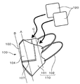
- FIG. 1 is a perspective view showing an example of a steam thermal mask 100.
- the steam thermal mask 100 is a combination of the mask 110 and the water vapor generator 120.
- FIG. 2 is a diagram illustrating an example of a usage state of the steam thermal mask 100.
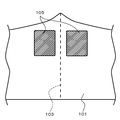
- FIG. 3 is a plan view of a part of the mask 110 according to the first embodiment as viewed from the wearer side.
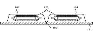
- FIG. 4 is a cross-sectional view of a part of the mask in the first embodiment as viewed from the upper surface (the eye side of the wearer).
- the steam thermal mask 100 is described as having the mask 110 and the steam generator 120 separated, and the steam generator 120 can be taken in and out of the container 104.
- the water vapor generator 120 may be sealed inside the container 104 of the mask 110.
- the mask 110 includes a mask main body 101 that covers the nose and mouth when worn, and a pair of ear hooks 102 provided at the left and right ends of the mask main body 101. Yes.
- the mask 110 is shown as having a fold line 103 at a position corresponding to the wearer's nasal bridge, but as a flat mask 110 having no fold line 103 in accordance with the application or the like. Also good.
- the shape of the mask 110 will be described with an example having the folding line 103.
- the mask main body 101 has a sheet shape. More specifically, the mask main body 101 is formed from a single sheet, and is folded symmetrically with respect to the fold line 103. Before use, the mask main body 101 is folded in a mountain shape along the fold line 103 and is folded into a flat shape. As shown in FIGS. 1 and 2, the fold line 103 has a substantially arc shape in which the nose is a convex part, and the upper part and the lower part are bonded together.
- the mask main body 101 is worn from the side opposite to the fold line 103 so that the inner surface on which the sheets are superimposed becomes the surface on the wearer side.
- the fold line 103 protrudes forward of the mask main body 101 when the mask 110 is worn.
- the folding line 103 is preferable because the upper part of the mask main body 101 closely adheres along the shape of the nose, so that a gap is less likely to be generated and the heating and humidifying effect can be enhanced.
- the single sheet forming the mask main body 101 may be a single structure (that is, one ply), or may be an integrated structure in which a plurality of sheets are stacked (that is, a multiply).
- a plurality of sheets it is preferable that various functions can be imparted to the cover portion by imparting separate functions to each sheet.
- the sheets may be in a laminated state where the sheets are joined together or in a state where the sheets are separated from each other. Further, when the sheets are separated from each other, the sheets may be joined together by sealing the edges of the sheets along the shape of the cover, or only part of the edges may be joined by a point seal. .
- FIG. 4 an example in which the mask main body 101 has a single structure will be described.
- the material of the mask body 101 can be any material conventionally used in the technical field of masks, and there is no particular limitation on the type as long as it has a certain air permeability.
- a fiber sheet such as a nonwoven fabric or gauze can be used, and it is preferable to use a nonwoven fabric from the viewpoint of ease of processing and economy.
- non-woven fiber materials include polyesters such as PET (polyethylene terephthalate); polyolefins such as PE (polyethylene), PP (polypropylene), and ethylene-propylene copolymers; rayon; one or two selected from cotton and the like What consists of the above fiber is preferable.
- the fiber of the said 1 type or 2 or more types of materials is used, an air through method, a spun bond method, a needle punch method, a melt blown method, a card method, a heat fusion method, a hydroentanglement method, a solvent adhesion method What was manufactured by the method etc. can be used.
- the mask main body 101 preferably has an appropriate ventilation resistance from the viewpoint of retaining the water vapor generated from the water vapor generator 120 in the mask 110 and from the viewpoint of making breathing easier.
- the ventilation resistance of the mask main body 101 is preferably 5 Pa or more, more preferably 20 Pa or more, and further preferably 50 Pa or more.
- the ventilation resistance of the mask body 101 is preferably 200 Pa or less, more preferably 190 Pa or less, and further preferably 180 Pa or less.
- the ventilation resistance of the mask body 101 is preferably 5 Pa or more and 200 Pa or less, more preferably 20 Pa or more and 190 Pa or less, and further preferably 50 Pa or more and 180 Pa or less.
- the ventilation resistance is measured in a state where all of a plurality of sheets are overlapped.
- the ventilation resistance of the mask main body 101 can be measured as follows. As shown in FIG. 10, a sheet 101a cut out to a size of 3.5 to 5 cm square from the sheet material of the mask body 101 is formed on the upper portion of the ventilation resistance evaluation apparatus body 70 of the mask tester MTS-2 (manufactured by Shibata Kagaku). It arrange
- the basis weight of the mask main body 101 is 5 g / m 2 or more from the viewpoint of preventing the inside of the mask 110 from being seen through and improving the heat retention, flexibility, thickness, and sheet strength in a balanced manner. It is preferably 10 g / m 2 or more, more preferably 30 g / m 2 or more, more preferably 200 g / m 2 or less, and 150 g / m 2 or less. More preferably, it is further preferably 120 g / m 2 or less.
- the basis weight is preferably 5 g / m 2 or more and 200 g / m 2 or less, more preferably 10 g / m 2 or more and 150 g / m 2 or less, and 30 g / m 2 or more and 120 g / m 2 or less. More preferably.
- the steam thermal mask 100 includes a steam generator 120.
- the water vapor generator 120 may be incorporated in the mask main body 101, or has a fixing means for fixing the water vapor generator 120 to the mask main body 101, and may be used by being fixed during use. Although it is good, in this embodiment, it fixes at the time of use.
- the mask body 101 is provided with a container 104 on the wearer side surface by a seal portion 107.
- the container 104 accommodates the water vapor generator 120 so that it can be taken in and out. Thereby, after using the mask 110, the mask 110 can be used many times by replacing the water vapor generator 120 with the one before use.
- the container 104 can be formed by a seal portion 107 a surrounding the outer periphery excluding the upper portions of the two water vapor generators 120 arranged in the lateral direction.
- the sheets constituting the container 104 are overlapped, the fold line 103 in the longitudinal center of the mask body 101 is sealed, and then the sealing portion 107a shown in FIG. 3 is sealed. It is done. Thereby, the pocket-shaped container 104 into which the water vapor generator 120 can be inserted from above the mask body 101 can be formed.
- 5 and 6 are plan views of a modification of the mask according to the first embodiment as viewed from the wearer's surface. That is, as shown in FIGS. 5 and 6, the container 104 configures the container 104 and the sheet constituting the mask body 101 at a position where a part of the lower part of the water vapor generator 120 is fixed. It may be formed by the seal portion 107b and the seal portion 107c to which the sheet is fixed.
- FIG. 5 and 6 are plan views of a modification of the mask according to the first embodiment as viewed from the wearer's surface. That is, as shown in FIGS. 5 and 6, the container 104 configures the container 104 and the sheet constituting the mask body 101 at a position where a part of the lower part of the water vapor generator 120 is fixed. It may be formed by the seal portion 107b and the seal portion 107c to which the sheet is fixed.
- FIG. 5 shows a straight line extending in the lateral direction of the central portion of the mask main body 101 so as to be in contact with the lower side of the water vapor generator 120 and a part of the lower portion of the side surface of the water vapor generator 120 on the ear hooking portion 102 side.
- a seal portion 107b consisting of a straight line extending in the vertical direction is shown.
- FIG. 6 shows a linear seal portion 107 c that is deformed along the shape of the lower part of the water vapor generator 120 in the lateral direction slightly above the center of the mask main body 101.
- the container 104 is fixed in the vicinity of the fold line 103 of the mask main body 101 and in the vicinity of the upper end of the mask main body 101 so that the water vapor generator 120 is attached to the mask main body 101 at a predetermined position. This is preferable because it can be fixed, and the space in the mask 110 from the nose to the cheek of the wearer can be easily heated and humidified.
- the container 104 has an opening so that the water vapor generator 120 can be taken in and out at the upper end or the ear hook 102 side, and the other end is fixed to the mask main body 101.
- the position of the opening is not particularly limited as long as the water vapor generator 120 does not come out of the container 104 when the mask 110 is worn.
- the size of the container 104 may be any as long as it can fix the position of the water vapor generator 120 while accommodating the water vapor generator 120.
- the container 104 has air permeability and can be made of the same material as the mask main body 101.
- the ventilation resistance of the container 104 is preferably 1 Pa or more and 100 Pa or less, more preferably from the viewpoint of effectively imparting the heating and humidifying performance by the water vapor generator 120 to the mask 110 while preventing excessive heat generation. Is 1 Pa to 50 Pa, more preferably 1 Pa to 30 Pa.
- the ear hooks 102 are used as a pair, and are respectively provided at the left and right ends of the mask body 101 in the longitudinal direction (X direction).
- the ear hooking portion 102 is formed of a string-like material having elasticity such as a rubber strap at the end of the mask main body 101.
- an elastic member integrated with the mask main body 101 may be used.
- the ear hook 102 may be made of the same material as the mask main body 101 or may be made of a different material.
- the water vapor generator 120 is attached to the mask main body 101.
- steam generator 120 was set to the specific ratio with respect to the area of the whole surface by the side of the wearer of the mask main-body part 101, and in addition to this, this water vapor
- the ratio of the area occupied by the water vapor generator 120 to the area of the entire wearer side surface of the mask body 101 is 30% or more from the viewpoint of increasing the absolute humidity inside the mask 110 when using the mask, Preferably it is 40% or more, More preferably, it is 45% or more.
- the ratio of the area occupied by the water vapor generator 120 to the area of the entire wearer-side surface of the mask main body 101 is 80% or less, preferably 70, from the viewpoint of ensuring appropriate air permeability as the mask 110. % Or less, more preferably 65% or less.
- the ratio of the area occupied by the water vapor generator 120 to the area of the entire wearer-side surface of the mask body 101 is 30% to 80%, preferably 40% to 70%. More preferably, it is 45% or more and 65% or less.
- the area of the entire wearer-side surface of the mask main body 101 refers to the entire surface of the sheet constituting the mask main body 101, including the area of the provided water vapor generator 120,
- the hanger 102 is not included. More specifically, when the mask is folded in the vertical direction at the center, the point on the folding line that is the furthest away from the line (A line) connecting the uppermost and lowermost separated points vertically in the direction of the distal end. And a portion from a line parallel to the A line (B line) passing through the mask tip to a line (C line) spaced 7 cm in parallel in the ear-hook direction.
- the distance is measured with the end on the ear hooking side of the seal width part as the front end. Furthermore, in the case of a pleated mask, the mask is stretched up and down and folded symmetrically with the crease at the center of the mask stretched, and the distance is measured. Does not add to the area. Even if the ear hook 102 is formed of a fiber sheet or the like, this region is not included in the area of the entire wearer-side surface of the mask main body 101.
- the area of the water vapor generator 120 is an area in a planar shape of a bag body 122 that houses a water vapor generator 121 described later, and indicates an area including a seal portion of a sheet constituting the bag body.
- the water vapor generator 120 is attached to the mask main body 101.
- the position of the water vapor generator 120 suppresses the generation of water vapor by creating a space between the nose and cheeks and a space surrounded by the water vapor generator 120 on the skin side of the mask body 101 when worn. 1 and 2, from the viewpoint of increasing the temperature and absolute humidity in the mask 110, as shown in FIGS. Is preferred.
- the vicinity of the fold line 103 and the vicinity of the upper end of the mask main body 101 are not limited to the case where the fold line 103 and the upper end of the mask main body 101 are in contact with each other. It is the area
- the water vapor generator 120 may reach the wearer's cheek, but it does not cover only the cheek. This is preferable from the viewpoint of increasing the temperature and absolute humidity in the mask 110 without suppressing the generation of water vapor.
- the position of the water vapor generator 120 is when the nose side end of the water vapor generator 120 is linear from the viewpoint of increasing the temperature and absolute humidity in the mask 110 without suppressing the generation of water vapor when the mask 110 is mounted.
- the shortest distance from the folding line 103 of the curved line is It is preferably 15 mm or less, more preferably 10 mm or less, and even more preferably 5 mm or less.
- the position of the water vapor generator 120 is preferably such that the shortest distance from the upper end of the mask body 101 at the upper end of the water vapor generator 120 is 15 mm or less, and preferably 10 mm or less. More preferably, it is 5 mm or less.
- the planar shape of the water vapor generator 120 is not particularly limited, and may be a circle, a polygon, or the like. From the viewpoint of production efficiency, ease of handling, and heating and humidifying effect, a rectangle such as a rectangle or a substantially square is preferable, and a substantially square is more preferable from the viewpoint of ease of handling. Moreover, when the nose side edge part of the water vapor generation body 120 is linear, it is preferable that the part which touches the water vapor generation body 120 of the fold line 103 of the mask main-body part 101 is linear.
- the vertical rigidity value measured under the following conditions of the water vapor generator 120 maintains the shape of the mask and improves the absolute humidity inside the mask. Accordingly, from the viewpoint of preventing breathlessness due to inhibition of ventilation, the width is preferably 30 gf / 60 mm width or more, more preferably 60 gf / 60 mm width or more, and further preferably 70 gf / 60 mm width or more.
- the vertical rigidity value of the water vapor generator 120 is preferably 150 gf / 60 mm width or less, more preferably 130 gf / 60 mm width or less, and further preferably, from the viewpoint of improving the wearing comfort during wearing. Is 120 gf / 60 mm width or less.
- the vertical stiffness value measured under the following conditions of the water vapor generator 120 is preferably 30 gf / 60 mm width to 150 gf / 60 mm width, and more preferably 60 gf / 60 mm width to 130 gf / 60 mm width. More preferably, it is 70 gf / 60 mm width or more and 120 gf / 60 mm width or less.
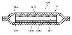
- the water vapor generator 120 contains a water vapor generator 121 inside.
- the water vapor generator 120 includes a water vapor generator 121 and a bag body 122 that accommodates the water vapor generator 121.
- the bag body 122 includes a first sheet 122A on the surface on the wearer side (skin side) and a second sheet 122B on the surface opposite to the surface on the wearer side (skin side).
- the water vapor generator 120 generates heat while generating water vapor by reacting with oxygen in the air.
- the water vapor generator 120 In a case where the water vapor generator 120 can be attached to and detached from the mask 110, the water vapor generator 120 is contained in an oxygen shielding bag before use.
- the oxygen barrier bag as a whole has an oxygen barrier property so that the water vapor generator 120 does not come into contact with oxygen in the air.
- the oxygen barrier material of the oxygen barrier bag include an oxygen permeability coefficient (ASTM D3985) of 10 cm 3 ⁇ mm / (m 2 ⁇ day ⁇ MPa) or less, particularly 2 cm 3 ⁇ mm / (m 2 ⁇ day ⁇ MPa. The following are preferred.
- a film such as an ethylene-vinyl alcohol copolymer or polyacrylonitrile, or a film obtained by vapor-depositing ceramic or aluminum on such a film can be used.
- the entire mask 110 is sealed in an oxygen blocking bag to avoid contact between the steam generator 120 and oxygen in the air. That's fine.
- the water vapor generating unit 121 can take various forms.
- the water vapor generating unit 121 may be, for example, any of a powder mixture, a sheet shape such as a papermaking sheet, or a coated sheet obtained by applying a dispersion liquid or the like to a base material.
- the steam generation unit 121 may include an aspect in which an oxidizable metal, a water absorbing agent, water, an electrolyte, and other reaction accelerators are included as necessary.
- an oxidation reaction of an oxidizable metal contained therein occurs and heat is generated.
- the water contained in the water vapor generating part 121 is heated by this heat to become water vapor at a predetermined temperature, and is discharged to the outside through the bag body 122.
- the water vapor is released from the breathable portion of the bag body 122 to the outside.
- the oxidizable metal is a metal that generates oxidation reaction heat, and examples thereof include one or more powders or fibers selected from iron, aluminum, zinc, manganese, magnesium, and calcium. Among these, iron powder is preferable from the viewpoints of handleability, safety, manufacturing cost, storage stability, and stability. Examples of the iron powder include one or more selected from reduced iron powder and atomized iron powder.
- the average particle size is preferably 0.1 ⁇ m or more, more preferably 10 ⁇ m or more, and more preferably 20 ⁇ m or more from the viewpoint that the oxidation reaction is efficiently performed. More preferably it is. From the same viewpoint, it is preferably 300 ⁇ m or less, more preferably 200 ⁇ m or less, and further preferably 150 ⁇ m or less. Furthermore, from the viewpoint of improving coatability, the average particle diameter is preferably 10 ⁇ m or more and 200 ⁇ m or less, and the average particle diameter is more preferably 20 ⁇ m or more and 150 ⁇ m or less.
- a material having a particle size of 0.1 to 150 ⁇ m and containing 50% by mass or more is preferable to use a material having a particle size of 0.1 to 150 ⁇ m and containing 50% by mass or more.
- the particle size of the oxidizable metal is the maximum length in the form of powder, and is measured by classification using a sieve, dynamic light scattering method, laser diffraction / scattering method, or the like.
- the content of the oxidizable metal in the water vapor generating part 121 is preferably 100 g / m 2 or more, more preferably 200 g / m 2 or more, expressed as basis weight.
- the content of oxidizable metal in the steam generator 121 is preferably represented by the basis weight is 3000 g / m 2 or less, and more preferably 1600 g / m 2 or less. Also, preferably, 100 g / m 2 or more 3000 g / m 2 or less, further preferably 200 g / m 2 or more 1600 g / m 2 or less. Thereby, the heat generation temperature of the steam generator 120 can be raised to a desired temperature.
- the content of the oxidizable metal can be determined by an ash content test according to JIS P8128 or a thermogravimetric instrument.
- it can be quantified by a vibration sample type magnetization measurement test or the like using the property that magnetization occurs when an external magnetic field is applied.
- the type of water-absorbing agent is not particularly limited as long as it can retain water, but for example, one or two selected from a carbon component, a fibrous material, a water-absorbing polymer, and a water-absorbing powder. More than species.
- a water absorbing agent an appropriate one is used according to the form of the water vapor generating unit 121.
- the carbon component those having water retention ability, oxygen supply ability, and catalytic ability can be used.
- one or more kinds selected from activated carbon, acetylene black, and graphite can be used.
- activated carbon is preferable, and one or more fine powders or small particles selected from coconut shell charcoal, wood powder charcoal, and peat charcoal are more preferable.
- charcoal is more preferable from the viewpoint of obtaining a good warming and humidifying effect.
- the water absorbing agent preferably has an average particle size of 10 ⁇ m or more, more preferably 12 ⁇ m or more.
- the water absorbing agent preferably has an average particle size of 200 ⁇ m or less, and more preferably 100 ⁇ m or less.
- the water absorbing agent preferably has an average particle size of 10 ⁇ m or more and 200 ⁇ m or less, and more preferably an average particle size of 12 ⁇ m or more and 100 ⁇ m or less.
- the average particle diameter of the water-absorbing agent refers to the maximum length in the form of powder and is measured by a dynamic light scattering method, a laser diffraction method, or the like.
- the carbon component is preferably used in a powder form, but a form other than the powder form can also be used, for example, a fibrous form can be used.
- a natural or synthetic fibrous material can be used without any particular limitation.
- natural fibrous materials include cotton, kabok, wood pulp, non-wood pulp, peanut protein fiber, corn protein fiber, soy protein fiber, mannan fiber, rubber fiber, hemp, manila hemp, sisal hemp, New Zealand hemp, rabu hemp , Plant fibers such as eggplant, igusa and straw.
- animal fibers such as wool, goat hair, mohair, cashmere, alpaca, Angola, camel, vicuuna, silk, feathers, down, feather, argin fiber, chitin fiber, and casein fiber can be mentioned.
- mineral fibers, such as asbestos are mentioned.
- examples of synthetic fibrous materials include semi-synthetic fibers such as rayon, viscose rayon, cupra, acetate, triacetate, oxide acetate, promix, chlorinated rubber, and hydrochloric acid rubber.
- semi-synthetic fibers such as rayon, viscose rayon, cupra, acetate, triacetate, oxide acetate, promix, chlorinated rubber, and hydrochloric acid rubber.
- polyesters such as polyethylene terephthalate
- synthetic polymer fibers such as polyacrylonitrile, acrylic, polyethylene, polypropylene, polystyrene, and polyurethane can be used.
- metal fiber, carbon fiber, glass fiber, etc. can also be used. These fibers can be used alone or in combination.
- wood pulp, cotton, polyethylene fiber, Polyester fibers are preferably used.
- wood pulp and cotton have a function of supporting and fixing a solid material such as iron powder.
- water-absorbing polymer examples include a hydrophilic polymer having a crosslinked structure capable of absorbing and retaining a liquid having a weight 20 times or more of its own weight.
- water-absorbing powder examples include one or more selected from vermiculite, calcium silicate, sawdust, alumina, silica gel, and pulp powder.
- the water vapor generating part 121 When the water vapor generating part 121 is in the form of a sheet, it is preferable to use a fibrous material as the water absorbing agent. This is because the fibrous material has a function as a water retention material and the water vapor generation part 121 has a function of maintaining the sheet form. As a result, the oxidizable metal is less likely to be biased, and the water vapor generation unit 121 has a uniform heat generation temperature distribution.
- the water vapor generating part 121 is a mixture made of powder
- the content of the water-absorbing agent is preferably 0.3 parts by mass or more, more preferably 1 part by mass or more, and further preferably 3 parts by mass or more with respect to 100 parts by mass of the oxidizable metal. Further, the content of the water absorbing agent is preferably 100 parts by mass or less, more preferably 80 parts by mass or less, and further preferably 60 parts by mass or less with respect to 100 parts by mass of the oxidizable metal. In addition, the content of the water-absorbing agent is preferably 0.3 parts by mass or more and 100 parts by mass or less, more preferably 1 part by mass or more and 80 parts by mass or less, with respect to 100 parts by mass of the oxidizable metal. More preferred is less than or equal to parts by weight.
- water necessary for maintaining the oxidation reaction can be accumulated in the water vapor generator 120 obtained. Further, it is possible to obtain the water vapor generator 120 with sufficient oxygen supply to the water vapor generator 121 and high heat generation efficiency. Moreover, since the heat capacity of the water vapor generator 120 with respect to the heat generation amount obtained can be kept small, the heat generation temperature increase is increased, a desired temperature increase is obtained, and the heat generation reaction can be promoted.
- the content of the water-absorbing agent is preferably 4 g / m 2 or more and 290 g / m 2 or less, more preferably 7 g / m 2 or more and 160 g / m 2 or less, expressed as basis weight.
- production part 121 can be made thin, and it does not become bulky as a product, but a flexibility comes out.
- the thickness of the water vapor generating part 121 can be set to 0.1 mm or more and 2 mm or less.
- Examples of the electrolyte include alkali metal, alkaline earth metal, or transition metal sulfates, carbonates, chlorides, hydroxides, and the like.
- chlorides of alkali metals, alkaline earth metals or transition metals are preferably used from the viewpoint of excellent conductivity, chemical stability and production cost, and particularly sodium chloride, potassium chloride, calcium chloride, magnesium chloride, chloride.
- Ferrous and ferric chloride are preferably used.
- the water vapor generating unit 121 contains water.
- Water may be derived from an aqueous electrolyte solution (for example, an aqueous solution of an alkali metal, an alkaline earth metal, etc.), or may be water alone and added to the water vapor generating part 121, and is not particularly limited.
- the water content in the water vapor generation part 121 is 35 parts by mass or more and 200 parts by mass or less with respect to 100 parts by mass of the oxidizable metal.
- the water vapor generation part 121 By setting the water content of the water vapor generation part 121 to 200 parts by mass or less with respect to 100 parts by mass of the oxidizable metal, the water vapor generation part 121 generates heat well and the rise of the heat generation temperature is quick (the temperature rise time is fast). Become).
- the water content necessary for the exothermic reaction of the water vapor generation unit 121 can be secured. The exothermic reaction can be maintained well.
- the water vapor generating part 121 in a good heat generation state can be obtained. . That is, the amount of water in the water vapor generating unit 121 affects the heat generation rate.
- the moisture content is 35 parts by mass or more and 200 parts by mass or less with respect to 100 parts by mass of the oxidizable metal, heat is generated satisfactorily, the rise of the exothermic temperature is fast, and the exothermic temperature is sustained.
- the water content of the water vapor generating part 121 is more preferably 40 parts by mass or more, and still more preferably 50 parts by mass or more with respect to 100 parts by mass of the oxidizable metal. Moreover, it is preferable that the water content of the water vapor
- the water content of the water vapor generating part 121 is more preferably 40 parts by mass or more and 150 parts by mass or less, and further preferably 50 parts by mass or more and 100 parts by mass or less, with respect to 100 parts by mass of the oxidizable metal. More preferably, it is 50 to 80 mass parts.
- the water vapor generating unit 121 includes a thickener, a surfactant, a drug, a flocculant, a colorant, a paper strength enhancer, a pH adjuster (for example, tripotassium phosphate), and a bulking agent. Etc. can also be included.
- a substance that absorbs moisture to increase consistency or impart thixotropy can be used.
- Alginates such as sodium alginate, gum arabic, gum tragacanth, locust bean gum, guar gum, carrageenan, agar, Polysaccharide thickeners such as xanthan gum; starch thickeners such as dextrin, pregelatinized starch and starch for processing; thickeners of cellulose derivatives such as carboxymethylcellulose, ethylcellulose, hydroxyethylcellulose, hydroxymethylcellulose or hydroxypropylcellulose; One or a mixture of two or more selected from thickeners such as polyvinyl alcohol (PVA); metal soap thickeners such as stearate; mineral thickeners such as bentonite; .
- PVA polyvinyl alcohol
- metal soap thickeners such as stearate
- mineral thickeners such as bentonite
- the content of the thickener is preferably 0.1 parts by mass or more with respect to 100 parts by mass of the oxidizable metal from the viewpoint of easy coating. More preferably, it is 2 parts by mass or more. Further, the content of the thickener is preferably 5 parts by mass or less, and more preferably 4 parts by mass or less with respect to 100 parts by mass of the oxidizable metal. The content of the thickener is preferably 0.1 parts by mass or more and 5 parts by mass or less, and more preferably 0.2 parts by mass or more and 4 parts by mass or less with respect to 100 parts by mass of the oxidizable metal. .
- production part 121 is a sheet form
- many holes and / or notches are formed.
- the area of the hole is preferably 0.01 to 10 mm 2 , particularly 0.1 to 8 mm 2 , since sufficient heat generation characteristics can be obtained.
- the shape of the hole examples include a circle, a rectangle, a polygon, an ellipse, an oval, or a combination of two or more thereof.
- the length is preferably 1 to 50 mm, particularly 5 to 30 mm.
- the water vapor generating unit 121 is accommodated in a bag body 122 including a first sheet 122A and a second sheet 122B of the water vapor generating body 120. That is, the water vapor generator 120 is configured to include the first sheet 122A and the second sheet 122B, and the peripheral portions of the first sheet 122A and the second sheet 122B are preferably hermetically bonded to form a bag body. 122 is configured. The region other than the peripheral portion of the first sheet 122A and the second sheet 122B is a non-joining region, and the water vapor generating part 121 is disposed in the non-joining region.
- the following configuration is adopted for the water vapor generation unit 121. That is, in the water vapor generator 120, the first sheet 122A is disposed on the wearer side surface of the water vapor generator 121, and the air permeability of the first sheet 122A is 7000 seconds / 100 ml or less.
- the second sheet 122B is disposed on the surface opposite to the wearer-side surface, and the air permeability of the second sheet 122B is more than 8000 seconds / 100 ml.
- the surface of the water vapor generator 120 located on the wearer side is the first sheet 122A.
- the air permeability of the first sheet 122A is 7000 seconds / 100 ml or less.
- the air permeability of the first sheet 122A maintains the space surrounded by the depressions of the face between the water vapor generator 120 and the nose and cheeks, ensures air permeability, and bags water vapor from the water vapor generator 120. From the viewpoint of easily releasing a large amount to the outside of the body 122, it is preferably 5000 seconds / 100 ml or less, more preferably 2500 seconds / 100 ml or less, further preferably 1000 seconds / 100 ml or less, further preferably 600 seconds.
- the first sheet 122A having such air permeability for example, a porous sheet made of a synthetic resin that has moisture permeability but does not have water permeability is suitable. Specifically, a stretched film containing calcium carbonate or the like in polyethylene can be used. When such a porous sheet is used, various fiber sheets including one or more nonwoven fabrics selected from needle punched nonwoven fabric, air-through nonwoven fabric, and spunbonded nonwoven fabric are laminated on the outer surface of the porous sheet. Then, the texture of the first sheet 122A may be enhanced. Further, the first sheet 122A may be a non-breathable sheet that does not have air permeability as long as the above air permeability is satisfied.
- a part of the second sheet 122B may be a breathable sheet having a breathability or a non-breathable sheet having no breathability, but a sheet having a low breathability is adopted as a whole. Is done. Specifically, the air permeability of the second sheet 122B is more than 8000 seconds / 100 ml. From the viewpoint of effectively heating and humidifying the inside of the mask body 101, a non-breathable sheet is used. Preferably there is.
- a single layer or multilayer synthetic resin film, a needle punch nonwoven fabric, an air-through nonwoven fabric on the outer surface of the single layer or multilayer synthetic resin film, Various fiber sheets including one or two or more kinds of nonwoven fabrics selected from spunbond nonwoven fabrics can be laminated to enhance the texture of the second sheet 122B.
- a two-layer film composed of a polyethylene film and a polyethylene terephthalate film, a laminate film composed of a polyethylene film and a nonwoven fabric, a laminate film composed of a polyethylene film and a pulp sheet, etc. are used. A film is even more preferred.
- the second sheet 122B can use the same material as the first sheet 122A or can use a different material as long as the above air permeability value is satisfied.
- the air permeability of the second sheet 122B is preferably 10,000 seconds / 100 ml or more, more preferably 30000 seconds / 100 ml or more, and more preferably 80000 seconds / 100 ml or more.
- the first sheet 122A has an air permeability of 2500 seconds / 100 ml or less, and the second sheet 122B. More preferably, the air permeability is 80,000 seconds / 100 ml or more.
- non-breathability is provided on the surface of the water vapor generating part 121 opposite to the surface on the wearer side, that is, between the water vapor generating part 121 and the outermost layer on the opposite side of the water vapor generating body 120 from the wearer.
- a non-breathable sheet more preferably a non-breathable sheet is disposed.
- a non-breathable sheet is disposed.
- it can suppress that the water vapor
- the water vapor generation unit 121 is, for example, in the form of a sheet
- the wet papermaking method described in Japanese Patent Application Laid-Open No. 2003-102761 or the extrusion method using a die coater according to the earlier application of the present applicant is used. Can do.
- a formed sheet containing an oxidizable metal, a water absorbing agent and a reaction accelerator is formed by a wet paper making method, and an aqueous electrolyte solution is added to the formed sheet, whereby the sheet-shaped water vapor generating part 121 is formed. can get.
- the obtained sheet-shaped water vapor generating part 121 may be used alone or in a plurality of layers.
- one water vapor generation unit 121 may be folded and a plurality of folded water vapor generation units 121 may be used in an overlapping manner.
- the powder water vapor generating part 121 is obtained by uniformly mixing the constituent materials. More specifically, first, a water-absorbing agent such as a superabsorbent polymer and an oxidizable metal are uniformly mixed, and an aqueous electrolyte solution is added thereto to adhere the oxidizable metal to the surface of the water-absorbing agent. Then, the water vapor generation part 121 can be prepared by adding the reaction accelerator etc. which are the remaining materials. By preparing the water vapor generating part 121 in this way, the rise time of the oxidation reaction is accelerated, and the amount of water vapor transpiration per unit time is easily maximized.
- a water-absorbing agent such as a superabsorbent polymer and an oxidizable metal
- an aqueous electrolyte solution is added thereto to adhere the oxidizable metal to the surface of the water-absorbing agent.
- the water vapor generation part 121 can be prepared by adding the reaction accelerator etc. which are the remaining materials.
- the exothermic powder water dispersion is applied to the water retaining sheet by, for example, the method described in Japanese Patent Application Laid-Open No. 2013-146554 related to the previous application of the present applicant. It may be obtained by cutting a continuous elongate material having a heat generation layer and a water retaining sheet into an arbitrary size.
- the water vapor generation unit 121 may be one or may be accommodated in a multilayer state in which a plurality of the water vapor generation units 121 are stacked.
- the water vapor generation part 121 has a water vapor generation layer 121A between the base material layer 121B and the water retention sheet 121C.
- the water vapor generation layer 121A and the water retention sheet 121C are in direct contact.
- the water vapor generating body 120 is located on the water retaining sheet 121C side, that is, the first sheet 122A side on the skin side of the wearer, and the base material layer 121B is second.
- the water vapor generation part 121 is provided so that it may be arrange
- the water vapor generation layer 121A may be provided on one surface of the water retention sheet 121C, or may be provided between the water retention sheet 121C and the base material layer 121B.
- FIG. 9 shows an example in which the water vapor generation layer 121A is provided in a form sandwiched between the water retention sheet 121C and the base material layer 121B.
- the water retention sheet 121C contains water.
- the water content can be, for example, 10% by mass or more and 45% by mass or less of the maximum water absorption amount of the water retention sheet 121C.
- the water content contained in the water retaining sheet 121C is preferably 50 to 350 g / m 2, more preferably 180 to 260 g / m 2 in terms of basis weight. Since the amount of water contained in the water retaining sheet 121C is a water vapor generation source, the amount of water contained in the water retaining sheet 121C is expressed in basis weight, preferably 50 g / m 2 or more, so that a good amount of steam is generated. It can be secured. In addition, the water retention sheet 121C generates airflow resistance due to water absorption (because of the water absorption swelling, the air permeability is lowered as compared with the time of drying).
- the air permeability of the water retaining sheet 121C is preferably 500 seconds / 100 ml or less in terms of moisture content, and is 300 seconds / 100 ml or less in consideration of air permeability and ease of vapor passage. Is more preferable, and it is more preferable that it is 50 seconds / 100 ml or less.
- the lower limit value of air permeability in a state containing moisture that is, the moisture amount is 15% by mass or more and 30% by mass or less of the maximum water absorption amount of the water retention sheet 121C) is, for example, 1 second / 100 ml.
- the water retaining sheet 121C a sheet material that can absorb and retain moisture and has flexibility is used.
- a material include fiber sheets such as paper, non-woven fabric, woven fabric, and knitted fabric made from fibers.
- porous bodies, such as sponge, etc. are mentioned.
- the fibers include those mainly composed of natural fibers such as plant fibers and animal fibers, and those mainly composed of chemical fibers.
- plant fibers include cotton, kabok, wood pulp, non-wood pulp, peanut protein fiber, corn protein fiber, soy protein fiber, mannan fiber, rubber fiber, hemp, Manila hemp, sisal hemp, New Zealand hemp, Rafu hemp, eggplant, One type or two or more types selected from igusa and straw are mentioned.
- animal fibers include one or more selected from wool, goat hair, mohair, cashmere, alpaca, Angola, camel, vicu ⁇ a, silk, feathers, down, feather, algin fiber, chitin fiber, and casein fiber.
- chemical fiber for example, one or more selected from rayon, acetate, and cellulose can be used.
- the water retaining sheet 121C preferably includes a fiber material composed of the above-described fibers and a water-absorbing polymer.
- the use of a hydrogel material that can absorb and retain a liquid having a weight 20 times or more of its own weight and can be gelled has a water content of the water retention sheet 121C of 15 to 15 times the maximum water absorption amount of the water retention sheet 121C. It can maintain at 30 mass%, and is preferable.
- the shape of the water-absorbing polymer particles include a spherical shape, a lump shape, a grape bunch shape, and a fiber shape. Further, the particle diameter of the water-absorbing polymer particles is preferably 1 ⁇ m or more, and more preferably 10 ⁇ m or more, from the viewpoint of easy handling during production.
- the particle diameter of the water-absorbing polymer particles is preferably 1000 ⁇ m or less, more preferably 500 ⁇ m or less, from the viewpoint of the water absorption rate.
- the particle diameter of the water-absorbing polymer particles is preferably 1 ⁇ m or more and 1000 ⁇ m or less, and more preferably 10 ⁇ m or more and 500 ⁇ m or less.
- the particle diameter of the water-absorbing polymer particles is measured by a dynamic light scattering method, a laser diffraction method, or the like.
- water-absorbing polymer examples are selected from starch, cross-linked carboxymethylated cellulose, polymer or copolymer of acrylic acid or alkali metal acrylate, polyacrylic acid and salts thereof, and polyacrylate graft polymer. 1 type or 2 types or more to be mentioned. Especially, it is preferable to use polyacrylic acid and its salt, and a polyacrylate graft polymer, such as a polymer or copolymer of acrylic acid or an alkali metal salt of acrylic acid.
- the base material layer 121B is provided on the surface opposite to the water retention sheet 121C of the water vapor generation layer 121A.
- the base material layer 121B is in direct contact with the water vapor generation layer 121A and covers the water vapor generation layer 121A.
- the base material layer 121B is preferably a non-breathable or non-breathable sheet.
- a resin sheet is preferably used.
- a non-breathable or non-breathable sheet 50000 seconds / 100 ml or more, preferably 80000 seconds / 100 ml or more
- the base material layer 121B include a synthetic resin film, such as a polyethylene film and a polyethylene terephthalate film.
- the water vapor generation unit 121 may be in direct contact with the second sheet 122B.
- a sheet having water resistance is preferable.
- the water vapor generation amount of the water vapor generator 120 of the present embodiment is preferably 30 mg / cell ⁇ 10 min or more, more preferably 50 mg / cell, as a whole, from the viewpoint of giving an appropriate vapor feeling to the mask wearer.
- Cell ⁇ 10 min or more more preferably 150 mg / cell ⁇ 10 min or more, further preferably 250 mg / cell ⁇ 10 min or more, and further preferably 300 mg / cell ⁇ 10 min or more.
- the water vapor generation amount of the water vapor generator 120 of the present embodiment is preferably 1200 mg / cell ⁇ 10 min or less, more preferably 1000 mg / cell, as a whole, from the viewpoint of suppressing dew condensation in the mask.
- the water vapor generation amount of the water vapor generator 120 of the present embodiment is preferably 30 mg / cell ⁇ 10 min to 1200 mg / cell ⁇ 10 min or less, more preferably 50 mg / cell ⁇ 10 min to 1000 mg as the whole water vapor generator 120.
- Cell ⁇ 10 min or less more preferably 150 mg / cell ⁇ 10 min to 800 mg / cell ⁇ 10 min or less, more preferably 250 mg / cell ⁇ 10 min to 700 mg / cell ⁇ 10 min or less, more preferably 300 mg / cell
- the amount of water vapor generated per unit area of the water vapor generator 120 of the present embodiment is preferably 1 mg / cm 2 ⁇ 10 min or more as a whole of the water vapor generator 120 from the viewpoint of giving an appropriate vapor feeling to the mask wearer. More preferably 1.5 mg / cm 2 ⁇ 10 min or more, further preferably 5 mg / cm 2 ⁇ 10 min or more, further preferably 7 mg / cm 2 ⁇ 10 min or more, and still more preferably 9 mg / cm is 2 ⁇ 10min or more.
- the amount of water vapor generated per unit area of the water vapor generator 120 of the present embodiment is preferably 20 mg / cm 2 ⁇ 10 min or less as a whole of the water vapor generator 120 from the viewpoint of suppressing dew condensation in the mask. It is preferably 18 mg / cm 2 ⁇ 10 min or less, more preferably 15 mg / cm 2 ⁇ 10 min or less.
- the water vapor generation amount per unit area of the water vapor generator 120 of the present embodiment is preferably 1 mg / cm 2 ⁇ 10 min to 20 mg / cm 2 ⁇ 10 min or less, more preferably 1 as the whole water vapor generator 120.
- the water vapor generation amount of the water vapor generator 120 or the steam thermal mask 100 is a numerical value measured as follows using the apparatus 30 shown in FIG.
- An apparatus 30 shown in FIG. 11 includes an aluminum measurement chamber (volume 2.1 L) 31, an inflow path 32 through which dehumidified air (humidity less than 2%, flow rate 2.1 L / min) flows into the lower portion of the measurement chamber 31, measurement An outflow path 33 through which air flows out from the upper part of the chamber 31, an inlet temperature / humidity meter 34 and an inlet flowmeter 35 provided in the inflow path 32, an outlet temperature / humidity meter 36 and an outlet flowmeter 37 provided in the outflow path 33, measurement It consists of a thermometer (thermistor) 38 provided in the chamber 31. A thermometer having a temperature resolution of about 0.01 ° C. is used.
- the surface temperature of the steam generator 120 or the surface of the steam thermal mask 100 located on the skin side is measured by taking the steam generator 120 out of the oxygen shielding bag at a measurement environment temperature of 30 ° C. (30 ⁇ 1 ° C.).
- a surface located on the skin side of the vapor thermal mask 100 that is, a water vapor discharge surface is placed on the measurement chamber 31, and a thermometer 38 with a metal ball (4.5 g) is placed thereon and measured. .
- dehumidified air is allowed to flow from the lower part, and a difference in absolute humidity before and after the air flows into the measurement chamber 31 is obtained from the temperature and humidity measured by the inlet temperature / humidity meter 34 and the outlet temperature / humidity meter 36.
- the amount of water vapor released from the water vapor generator 120 or the steam thermal mask 100 is calculated from the flow rate measured by the flow meter 35 and the outlet flow meter 37.
- the amount of water vapor generation in this specification means the total amount measured by 10 minutes after the time when the water vapor generator 120 is taken out from the oxygen shielding bag.
- the amount of water vapor generated by the steam thermal mask 100 of the present embodiment is preferably 60 mg / 10 min or more, more preferably 100 mg / 10 min or more, and still more preferably from the viewpoint of giving an appropriate steam feeling to the mask wearer. Is 300 mg / 10 min or more, more preferably 500 mg / 10 min or more, and even more preferably 600 mg / 10 min or more. In addition, the amount of water vapor generated in the steam thermal mask 100 of the present embodiment is preferably 2000 mg / 10 min or less, more preferably 1400 mg / 10 min or less, and even more preferably 1000 mg / min from the viewpoint of suppressing condensation in the mask. 10 min or less.
- the amount of water vapor generated in the steam thermal mask 100 of the present embodiment is preferably 60 mg / 10 min or more and 2000 mg / 10 min or less, more preferably 100 mg / 10 min or more and 1400 mg / 10 min or less, and further preferably 300 mg / 10 min or more. It is 1000 mg / 10min or less, More preferably, it is 500 mg / 10min or more and 1000 mg / 10min or less, More preferably, it is 600 mg / 10min or more and 1000 mg / 10min or less.
- the steam thermal mask 100 is a combination of the mask 110 and the steam generator 120 described above, and the surface of the steam generator 120 on the wearer side has a permeability of 7000 seconds / 100 ml or less. And a sheet having an air permeability of more than 8000 seconds / 100 ml is disposed on the surface of the water vapor generator 120 opposite to the surface on the wearer side.
- the air permeability of the first sheet 122A is 7000 seconds / 100 ml or less and the air permeability of the second sheet 122B is more than 8000 seconds / 100 ml
- the water vapor generated by the water vapor generating part 121 is Leakage to the outside can be suppressed, and water vapor can be applied to the inside of the mask 110, that is, to the wearer side.
- the ratio of the area occupied by the water vapor generator 120 to the area of the entire wearer-side surface of the mask main body 101 is set to 30% or more and 80% or less, so that the mask is not given to the wearer.
- the absolute humidity inside 110 can be increased.
- the steam thermal mask 100 is used as follows, for example. That is, when the mask 110 and the steam generator 120 are separated, the steam thermal mask 100 opens the oxygen blocking bag, takes out the steam generator 120, and fixes the mask 110 at a predetermined position.
- the mask 110 is mounted so that each ear hook portion 102 is hung on the wearer's ear and the mask main body portion 101 covers the mouth and nose of the wearer. Further, when the water vapor generator 120 is enclosed in the container 104 in the mask 110, the vapor thermal mask 100 as a whole is usually enclosed in an oxygen shielding bag.
- each ear hook 102 is put on the wearer's ear
- the mask main body 101 is put on the wearer's mouth and nose. Wear so that it covers.
- the water vapor generator 120 reacts with oxygen in the air to generate heat and generate water vapor.
- water vapor generated in the mask 110 is sucked from the wearer's mouth and nose, and the throat and nose dry feeling due to the low-temperature and low-humidity environment is reduced. Can get better. A feeling of falling asleep is also induced.
- the mucous membrane of the nasal cavity is heated and humidified, the foreign matter discharging function is enhanced, and a preventive effect such as a cold can be expected.
- the lip portion is sensitive to temperature because the stratum corneum is thin, and the heat generated by the water vapor generator 120 touches the lip portion, and it is easy to feel sensitively hot, but by warming the side portion of the nose, Such a problem can be suppressed.
- the maximum value of the absolute humidity in the mask while using the steam thermal mask 100 is preferably 12 g / m 3 or more, more preferably 13 g / m 3 or more, from the viewpoint of providing a comfortable vapor to the wearer. More preferably, it is 15 g / m 3 or more, more preferably 20 g / m 3 or more, and still more preferably 25 g / m 3 or more.
- the maximum value of the absolute humidity in the mask while using the steam thermal mask 100 is preferably 50 g / m 3 or less, more preferably 45 g / m 3 or less, from the viewpoint of preventing dew condensation in the mask.
- the maximum value of the absolute humidity in the mask during use of the steam thermal mask 100 is preferably 12 g / m 3 or more and 50 g / m 3 or less, more preferably 13 g / m 3 or more and 45 g / m 3 or less. even more preferably less 15 g / m 3 or more 40 g / m 3, more preferably less 20 g / m 3 or more 35 g / m 3, preferably in deliberately or less 25 g / m 3 or more 35 g / m 3.
- the average value of the absolute humidity in the mask during use of the steam thermal mask 100 is preferably 11.7 g / m 3 or more, more preferably 12 g, from the viewpoint of providing steam that is comfortable to the wearer. / M 3 or more, more preferably 13 g / m 3 or more, further preferably 15 g / m 3 or more, and even more preferably 19 g / m 3 or more. Moreover, the average value of the absolute humidity in the mask during use of the steam thermal mask 100 is preferably 35 g / m 3 or less, more preferably 30 g / m 3 or less, from the viewpoint of preventing dew condensation in the mask. More preferably, it is 25 g / m 3 or less.
- the average value of the absolute humidity in the mask in the moist heat mask 100 in use preferably not more than 11.7 g / m 3 or more 35 g / m 3, more preferably 12g / M 3 or more and 30 g / m 3 or less, more preferably 13 g / m 3 or more and 25 g / m 3 or less, further preferably 15 g / m 3 or more and 25 g / m 3 or less, and further preferably 19 g / m 3 or less. m 3 or more and 25 g / m 3 or less.
- the absolute humidity when using the steam thermal mask 100 can be measured as follows.
- a temperature / humidity sensor (SHT71 manufactured by Sensirion Co., Ltd.) is attached to the lower nose of the head model mannequin prepared using male human head data (average of 52 Japanese adult males) from Digital Human Technology Co., Ltd. in an environment of 20 ° C and 60% RH. ) And using a ventilator (HARVARD APPARATUS DUAL PHASE CONTROL RESPIRATOR (manufactured by HARVARD APPARATUS)) from the nose of the head model, imitating the respiratory rhythm of a person 15 times per minute, 500 ml per time Inhale at a frequency.
- HARVARD APPARATUS DUAL PHASE CONTROL RESPIRATOR manufactured by HARVARD APPARATUS
- the steam thermal mask 100 is attached to the mannequin, and temperature and humidity changes are measured and recorded.
- the recorder for example, EK-H4 manufactured by Sensirion Co., Ltd. is used.
- the absolute humidity is calculated from the temperature and the relative humidity, and the maximum absolute humidity and the average absolute humidity for 10 minutes are obtained.
- the air permeability of the first sheet is 7000 seconds / 100 ml or less and the air permeability of the second sheet is more than 8000 seconds / 100 ml has been described, but in the second embodiment, these first
- the air permeability of the sheet and the second sheet is set as follows. That is, in the present embodiment, the air permeability of the second sheet is 250 seconds / 100 ml or more and 8000 seconds / 100 ml or less, and the air permeability of the first sheet is 20% or less with respect to the air permeability of the second sheet.
- this embodiment will be described.
- description about the same structure and effect of 1st Embodiment is abbreviate
- a part of the second sheet 122B may be a breathable sheet having air permeability or a part of the second sheet 122B may be a non-breathable sheet having no breathability.
- the air permeability of the second sheet 122B a condition of 250 seconds / 100 ml or more and 8000 seconds / 100 ml or less is employed.
- the air permeability of the second sheet 122B is 4000 seconds / from the viewpoint of preventing abnormal heat generation of the steam generator, appropriately distributing the steam generated from the steam generating section 121, and sufficiently applying the steam to the wearer side. It is preferably 100 ml or more and 7500 seconds / 100 ml or less, more preferably 5000 seconds / 100 ml or more and 7000 seconds / 100 ml or less.
- a single layer or multilayer synthetic resin film, a needle punch nonwoven fabric, an air-through nonwoven fabric on the outer surface of the single layer or multilayer synthetic resin film, Various fiber sheets including one or two or more kinds of nonwoven fabrics selected from spunbond nonwoven fabrics can be laminated to enhance the texture of the second sheet 122B.
- a two-layer film composed of a polyethylene film and a polyethylene terephthalate film, a laminate film composed of a polyethylene film and a nonwoven fabric, a laminate film composed of a polyethylene film and a pulp sheet, etc. are used. A film is even more preferred.
- the air permeability of the first sheet 122A located on the wearer-side surface of the water vapor generator 120 is 20% or less of the air permeability of the second sheet 122B.
- the air permeability of the first sheet 122A appropriately distributes the water vapor generated from the water vapor generating unit 121, and sufficiently applies the water vapor to the wearer side.
- the air permeability of the second sheet 122B is preferably 10% or less, more preferably 5% or less, still more preferably 3% or less, and further preferably 1% or less. More preferably, it is 0%.
- the air permeability of the first sheet 122A can be appropriately selected from the conditions that it is 20% or less of the air permeability of the second sheet 122B.
- the water vapor generated from the water vapor generator 121 is appropriately distributed. From the viewpoint of sufficiently applying water vapor to the wearer, and from the viewpoint of preventing the breathing difficulty when wearing the steam thermal mask by suppressing the swelling of the water vapor generating body, more specifically, preferably 1600 seconds / 100 ml or less More preferably 1000 seconds / 100 ml or less, still more preferably 250 seconds / 100 ml or less, still more preferably 10 seconds / 100 ml or less, still more preferably 5 seconds / 100 ml or less, even more preferably 0 sec / 100 ml.
- the first sheet 122A having such air permeability for example, a porous sheet made of a synthetic resin that has moisture permeability but does not have water permeability is suitable. Specifically, a stretched film containing calcium carbonate or the like in polyethylene can be used. When such a porous sheet is used, various fiber sheets including one or more nonwoven fabrics selected from needle punched nonwoven fabric, air-through nonwoven fabric, and spunbonded nonwoven fabric are laminated on the outer surface of the porous sheet. Then, the texture of the first sheet 122A may be enhanced. Further, the first sheet 122A may be a non-breathable sheet that does not have air permeability as long as the above air permeability is satisfied.
- the air permeability of the second sheet 122B is 8000 seconds / 100 ml or less
- the air permeability of the first sheet 122A is 20% or less of the air permeability of the second sheet 122B.
- the ratio of the area occupied by the water vapor generator 120 to the area of the entire wearer-side surface of the mask main body 101 is set to 30% or more and 80% or less, so that the mask is not given to the wearer.
- the absolute humidity inside 110 can be increased.
- the synergistic effect of these effects allows you to breathe comfortably, actively generate warm water vapor in the mask, increase the absolute humidity in the mask, and improve the comfort and warmth of the throat and nasal mucosa. A moist feeling can be improved.
- FIG. 7 is a partial plan view seen from the wearer's surface before the water vapor generator is attached to the mask in the third embodiment.
- FIG. 8 is a cross-sectional view of a part of the mask in the third embodiment as viewed from the upper surface (the eye side of the wearer).
- the mask body 101 can be made of the same material as in the first and second embodiments.
- a marking region 105 is formed on the wearer-side surface of the mask main body 101 so that the position where the water vapor generator 120 is attached can be seen.
- the water vapor generator 120 is fixed to the mask main body 101 via the adhesive 106 on the marking region 105.
- the marking area 105 may be changed in color by printing or embossed.
- the marking area 105 may be provided with a line such as a solid line or a dotted line around it.
- a non-woven fabric such as an air-through non-woven fabric, which is a sheet material having a good texture, may be disposed between the first sheet 122A of the water vapor generator 120 and the wearer (not shown).
- the nonwoven fabric has an air permeability that does not hinder the passage of water vapor.
- the non-woven fabric has water repellency so as not to inhibit the passage of water vapor and to prevent the inflow of air due to the wetness of the nonwoven fabric with water vapor.
- Such a non-woven fabric may be formed on the first sheet 122A of the water vapor generator 120, is attached to the wearer side surface of the mask 110 so as to be opened and closed, and is closed after the water vapor generator 120 is pasted. It may be.
- the adhesive 106 is provided on the surface opposite to the wearer side of the water vapor generator 120, that is, the surface opposite to the wearer side of the second sheet 122B. Thereby, the water vapor generator 120 can be stably fixed to the mask 110.
- the pressure-sensitive adhesive 106 is not particularly limited in size and shape as long as it can fix at least the water vapor generator 120 to the mask main body 101.
- Hot melt pressure-sensitive adhesives generally contain a pressure-sensitive adhesive base, a tackifying resin, and a softening agent as constituent components.
- the types of hot melt adhesives include, for example, synthetic rubbers, polyolefins (Polyethylene (PE), Ethylene Vinyl Acetate (EVA), Ethylene-Ethyl-Acrylate (EEA), Athletic Polypropylene (APO), and Polypropylene (APP). Olefin (APAO) type, etc.), polyamide type (nylon type, polyamide type, etc.), polyester type, acrylic type and the like are included. These can be used alone or in combination of two or more. In particular, from the viewpoints of storage stability, adhesive strength, safety, etc., synthetic rubbers, polyolefins, acrylics, and polyamides are preferred, and synthetic rubbers are particularly preferred.
- the adhesive 106 is protected by the release paper and does not adhere to the outside before the steam thermal mask 100 is used.
- the release paper is not particularly limited and can be used.
- an adhesive may be provided on the wearer-side surface of the mask body 101. Specifically, a pair of symmetrically provided near the fold line 103 of the mask main body 101 and near the upper end of the mask main body 101. Thereby, the fixed position of the water vapor generator 120 is easily understood. In this case, it is preferable to use an adhesive that can be used repeatedly.
- the mask main body 101 is formed of a single sheet and is folded symmetrically on the fold line 103.
- the mask main body 101 has two identical shapes.
- the folding line 103 may be formed by overlapping sheets and bonding one side together.
- the sheet used in this case can be the same as that described in the above embodiments.
- the present invention further discloses the following composition, production method, or use.
- a mask provided with a mask main body that covers the nose and mouth of the wearer when worn, and a pair of ear hooks provided at the left and right ends of the mask main body,
- a steam thermal mask comprising a steam generator in the mask body, The ratio of the area occupied by the water vapor generator to the area of the entire wearer-side surface of the mask body is 30% or more and 80% or less,
- the water vapor generator contains a water vapor generating part inside,
- the water vapor generator comprises a first sheet on the wearer side surface of the water vapor generation unit, and a second sheet on the surface opposite to the wearer side surface of the water vapor generation unit,
- the air permeability of the first sheet is 7000 seconds / 100 ml or less,
- the air permeability of the second sheet is more than 8000 sec / 100 ml, Steam thermal mask.
- a mask provided with a mask main body that covers the nose and mouth of the wearer when worn, and a pair of ear hooks provided at the left and right ends of the mask main body,
- a steam thermal mask comprising a steam generator in the mask body, The ratio of the area occupied by the water vapor generator to the area of the entire wearer-side surface of the mask body is 30% or more and 80% or less,
- the water vapor generator contains a water vapor generating part inside,
- the water vapor generator comprises a first sheet on the wearer side surface of the water vapor generation unit, and a second sheet on the surface opposite to the wearer side surface of the water vapor generation unit,
- the air permeability of the second sheet is 250 seconds / 100 ml or more and 8000 seconds / 100 ml or less,
- the air permeability of the first sheet is 20% or less with respect to the air permeability of the second sheet, Steam thermal mask.
- the vertical stiffness value of the water vapor generator is preferably 30 gf / 60 mm width or more, more preferably 60 gf / 60 mm width or more, and further preferably 70 gf / 60 mm width or more, ⁇ 1> or ⁇ 2 > Steam thermal mask.
- the vertical stiffness value of the water vapor generator is preferably 150 gf / 60 mm width or less, more preferably 130 gf / 60 mm width or less, and even more preferably 120 gf / 60 mm width or less.
- the steam thermal mask according to any one of the above.
- the maximum value of the absolute humidity in the mask during use of the steam thermal mask is preferably 12 g / m 3 or more, more preferably 13 g / m 3 or more, and even more preferably 15 g / m 3 or more.
- the maximum value of absolute humidity in the mask during use of the steam thermal mask is preferably 50 g / m 3 or less, more preferably 45 g / m 3 or less, and even more preferably 40 g / m 3 or less.
- ⁇ 9> Any one of ⁇ 1> to ⁇ 8>, wherein the basis weight of the mask body is preferably 5 g / m 2 or more, more preferably 10 g / m 2 or more, and further preferably 30 g / m 2 or more. Steam thermal mask according to crab. ⁇ 10> Any one of ⁇ 1> to ⁇ 9>, wherein the basis weight of the mask body is preferably 200 g / m 2 or less, more preferably 150 g / m 2 or less, and even more preferably 120 g / m 2 or less. Steam thermal mask according to crab.
- the content of the water absorbing agent is preferably 0.3 parts by mass or more, more preferably 1 part by mass or more, and further preferably 3 parts by mass or more with respect to 100 parts by mass of the oxidizable metal.
- the content of the water absorbing agent is preferably 100 parts by mass or less, more preferably 80 parts by mass or less, and even more preferably 60 parts by mass or less, with respect to 100 parts by mass of the oxidizable metal.
- the steam thermal mask according to ⁇ 12>. ⁇ 14> The water content of the water vapor generating part is preferably 35 parts by mass or more, more preferably 40 parts by mass or more, further preferably 50 parts by mass or more with respect to 100 parts by mass of the oxidizable metal.
- the steam thermal mask according to any one of 11> to ⁇ 13>. ⁇ 15> The water content of the water vapor generating part is preferably 200 parts by mass or less, more preferably 150 parts by mass or less, still more preferably 100 parts by mass or less, with respect to 100 parts by mass of the oxidizable metal.
- the water vapor generation amount of the water vapor generator as a whole is preferably 30 mg / cell ⁇ 10 min or more, more preferably 50 mg / cell ⁇ 10 min or more, and further preferably 150 mg / cell ⁇ 10 min or more.
- the water vapor generation amount of the water vapor generator as a whole is preferably 1200 mg / cell ⁇ 10 min or less, more preferably 1000 mg / cell ⁇ 10 min or less, and further preferably 800 mg / cell ⁇ 10 min or less.
- the steam thermal mask according to any one of ⁇ 1> to ⁇ 16>, more preferably 700 mg / cell ⁇ 10 min or less, and further preferably 500 mg / cell ⁇ 10 min or less.
- the amount of water vapor generated per unit area of the water vapor generator is, as a whole, preferably 1 mg / cm 2 ⁇ 10 min or more, more preferably 1.5 mg / cm 2 ⁇ 10 min or more, more preferably 5 mg / cm 2 ⁇ 10 min or more, more preferably 7 mg / cm 2 ⁇ 10 min or more, and even more preferably 9 mg / cm 2 ⁇ 10 min or more, according to any one of ⁇ 1> to ⁇ 17> Steam thermal mask.
- the total amount of water vapor generated per unit area of the water vapor generator is preferably 20 mg / cm 2 ⁇ 10 min or less, more preferably 18 mg / cm 2 ⁇ 10 min or less, and even more preferably 15 mg / cm 2.
- the steam thermal mask according to any one of ⁇ 1> to ⁇ 18>, which is cm 2 ⁇ 10 min or less.
- the amount of water vapor generated by the steam thermal mask is preferably 60 mg / 10 min or more, more preferably 100 mg / 10 min or more, further preferably 300 mg / 10 min or more, and further preferably 500 mg / 10 min or more.
- the steam thermal mask according to any one of ⁇ 1> to ⁇ 19>, which is 600 mg / 10 min or more.
- the steam generation amount of the steam thermal mask is preferably 2000 mg / 10 min or less, more preferably 1400 mg / 10 min or less, and further preferably 1000 mg / 10 min or less, ⁇ 1> to ⁇ 20> The steam thermal mask described.
- the average value of the absolute humidity in the mask during use of the moist heat mask preferably 11.7 g / m 3 or more, more preferably 12 g / m 3 or more, more preferably 13 g / m 3 or more Yes, more preferably 15 g / m 3 or more, and even more preferably 19 g / m 3 or more, the steam thermal mask according to any one of ⁇ 1> to ⁇ 21>.
- the average value of the absolute humidity in the mask during use of the steam thermal mask is preferably 35 g / m 3 or less, more preferably 30 g / m 3 or less, and even more preferably 25 g / m 3 or less.
- Example A (Example A1) A vapor thermal mask 100 similar to that described in the first embodiment was produced. Specifically, it is as follows. ⁇ Preparation of water vapor generation part 121> Exothermic compositions having the compositions shown in Table 1 were prepared by the following procedure. A thickener was dissolved in water, and then tripotassium phosphate was dissolved to prepare an aqueous solution. On the other hand, a powder in which iron powder and activated carbon were premixed was prepared, and the premixed powder was put into the aqueous solution, and stirred at 150 rpm for 10 minutes with a disk turbine type stirring blade to obtain a slurry-like exothermic composition.
- the obtained exothermic composition is 1.4 g per one (4.9 cm ⁇ 4.9 cm; area 24.0 cm 2 ) of the water vapor generating part 121. Coated so that. Furthermore, salt (Japanese Pharmacopoeia (manufactured by Otsuka Pharmaceutical Co., Ltd.)) is sprayed on the coated surface so as to be 0.07 g per one of the water vapor generating part 121 (same as above) to form a water vapor generating layer 121A.
- the water vapor generation part 121 was produced by stacking the water retention sheet 121C thereon.
- a polyethylene film having a basis weight of 27 g / m 2 was used.
- water retention sheet 121C wood pulp paper (weighing 20 g / m 2 , manufactured by Ino Paper Co., Ltd.) and water-absorbing polymer (sodium polyacrylate, spherical, average particle size 300 ⁇ m, weighing 50 g / m 2 , Aquaric CA) , Manufactured by Nippon Shokubai Co., Ltd.) and wood pulp paper (basis weight 30 g / m 2 , manufactured by Ino Paper Co., Ltd.) were laminated and integrated.
- the water vapor generation part 121 obtained in this way was stacked in two layers (mass 3.43 g) so that the water retention sheet 121C was arranged on the skin side (first sheet 122A side).
- the water content in the water vapor generation part 121 immediately after the production was 62 parts by mass with respect to 100 parts by mass of the iron powder.
- a non-breathable sheet having a basis weight of 40 g / m 2 obtained by laminating a film of 100% by mass of polyethylene and a pulp sheet was used as the second sheet 122B of the water vapor generator 120 (hereinafter the same).
- the water vapor generating part 121 was disposed between the first sheet 122A and the second sheet 122B, and the peripheral part was hermetically sealed to obtain the water vapor generating body 120.
- the base material layer 121B of the water vapor generation unit 121 was disposed on the second sheet 122B side.
- the area of the first sheet 122A including the ventilation surface and the seal portion was 39.7 cm 2 (6.3 cm ⁇ 6.3 cm).
- the steam generator 120 was stored in an oxygen-blocking bag until evaluation described below was performed.
- an SMS nonwoven fabric spunbond (polypropylene) -meltblown (polypropylene) -spunbond (polypropylene) laminated integrated type, basis weight 50 g / m 2 ) is outside, basis weight 25 g.
- Two layers were layered so that the spunbonded nonwoven fabric (polypropylene) would be on the inside (wearer side). At this time, the blocking rate of 0.3 ⁇ m or more particles of the mask main body 101 was 25%.
- a stretchable rubber string-like ear hook 102 was attached to the end of the mask body 101 to produce a mask 110 having a three-dimensional shape.
- the ventilation resistance of the mask body 101 was measured at the container portion, it was 148 Pa / 30 mm ⁇ ⁇ pressure difference.
- each of the steam generators 120 is placed in the container 104 (two in total) from the upper side of the mask 110 where the two nonwoven fabrics of the mask main body 101 are not heat-sealed.
- a pair of water vapor generators 120 are attached symmetrically in the vicinity of the fold line 103 of the main body 101 and the upper end of the mask main body 101 (side of the nose) to form a steam thermal mask 100.
- the area of the entire wearer side surface of the mask body 101 was calculated by the following method. The mask body 101 is folded in the vertical direction at the central portion, and the end of the seal portion on the ear hooking side at the point on the folding line that is perpendicularly farthest from the line (line A) connecting the upper and lowermost separated points vertically.
- A4 paper Toppan Forms, Recycled Cut G80A4W, basis weight 64 g / m 2 , 21.0 cm ⁇ 29.7 cm: area 623.7 cm 2 ).
- A4 paper Toppan Forms, Recycled Cut G80A4W, basis weight 64 g / m 2 , 21.0 cm ⁇ 29.7 cm: area 623.7 cm 2 ).
- the mass of the cut paper was measured.
- the area of the entire surface on the wearer side of the mask main body 101 is 152.0 cm 2.
- the area ratio of the two left and right steam generators 120 to the area of the entire wearer-side surface of the portion 101 was 52%.
- Examples A2 and A3 As the first sheet 122A of the water vapor generator 120, synthetic pulp paper having an air permeability of 4.0 seconds / 100 ml and a basis weight of 40 g / m 2 (trade name: Eleven MOA, manufactured by Tokai Pulp Co., Ltd.) is used. 1 in Example A2 and 2 sheets in Example A3. Other than that, the vapor thermal mask 100 was produced by the same method as Example A1.
- Examples A4 to A8 As the first sheet 122A of the water vapor generator 120, a calcium carbonate-containing polyethylene film having an air permeability shown in Table 3 and having a basis weight of 50 g / m 2 (trade name: TSF-EU, manufactured by Kojin Co., Ltd.) is used. A vapor thermal mask 100 was produced by the same method as in Example A1 except that.
- Examples A9 to A11 As the second sheet 122B of the water vapor generator 120, a calcium carbonate-containing polyethylene film having the air permeability shown in Table 3 and having a basis weight of 50 g / m 2 (trade name: TSF-EU, manufactured by Kojin Co., Ltd.) is used. A vapor thermal mask 100 was produced by the same method as in Example A1 except that.
- Example A12, A13 and Comparative Example A1 The water vapor generating part 121 (4.9 cm ⁇ 4.9 cm; area 24.0 cm 2 ) of Example A1 cut into a size of 3.3 cm ⁇ 3.3 cm (area 10.9 cm 2 ) was used as the water vapor generating part. used.
- the sizes of the first sheet and the second sheet are 4.8 cm ⁇ 4.8 cm (area 23.0 cm 2 ) in Example A12 and 5.5 cm ⁇ 5. 5 in Example A13.
- Examples A14 and A15 and Comparative Example A2 In the production of the water vapor generating part 121, when the exothermic composition is die-coated on one surface of the base material layer 121B, one size of the water vapor generating part 121 is 4.9 cm ⁇ 6.5 cm (area 31 in Example A14). .9cm 2), 4.9cm ⁇ 7.5cm (area 36.8Cm 2 in example A15), as Comparative example A2 the 4.9 cm ⁇ 8.5 cm (area 41.7cm 2), the coating amount of the heat-generating composition was made to have the same thickness as that of Example A1 (1.4 g in terms of 4.9 cm ⁇ 4.9 cm).
- the sizes of the first sheet and the second sheet were 6.3 cm ⁇ 8.4 cm (area 52.9 cm 2 ) in Example A14 and 6.3 cm ⁇ 9. 6 cm (area 60.5cm 2), as Comparative example A2 the 6.4 cm ⁇ 10.6 cm (area 67.8cm 2), by placing the steam generator 121 during each sheet and hermetically sealed to the periphery A steam generator 120 was obtained.
- steam generator 120 with respect to the area of the whole surface at the side of the wearer of the mask main-body part 101 is described in Table 3. It was supposed to be.
- Example A16 and A17 As the water vapor generating part, only one layer of the water vapor generating part 121 used in Example A1 was used, and the water vapor generator 120 was used according to Example A1, except that the first sheet having the air permeability shown in Table 3 was used. Was made.
- Example A16 the vapor thermal mask 100 was produced in the same manner as in Example A1, and for Example A17, the produced water vapor generator was added during the production of the vapor thermal mask.
- Two sheets of ADVANTEC (registered trademark) qualitative filter paper No. 2 cut into a size of 63 mm square so as to contact two sheets were laminated to produce a steam thermal mask 100.
- Example A18 and A19 As the water vapor generating part, a powdery exothermic composition having the composition shown in Table 2 was prepared by the following procedure. Under a nitrogen stream, iron powder, water, sodium chloride, a water-absorbing polymer and activated carbon were mixed until uniform to produce a powdery water vapor generating part. In the production of the water vapor generator 120, Example A18 was replaced with Example A1 and Example A19 was replaced with the sheet-shaped water vapor generator 121 in Example A8. A vapor thermal mask 100 was produced in the same manner as in Example A1 except that it was used.
- the oxygen barrier bag (packaging material) was opened, and the produced water vapor generator 120 was taken out and immediately set on the mask 110, and the following evaluation was performed.
- the results are shown in Table 3.
- the bending rigidity value of the mask set was measured using a Tensilon universal testing machine (ORIENTEC RTC-1150A).
- the bending rigidity value was measured in a state in which the folding line of the mask main body was cut out and one side of the mask was used and one cell of the water vapor generator was inserted into the mask container.
- the measurement condition is that the steam generator is supported at a span distance of 30 mm, and a load is applied to the center of the test piece (steam generator) at a crosshead speed of 20 mm / min with a plate-like pressing member having a width of 60 mm and a tip radius of 5 mm. Gave.
- the peak load at this time was taken as the rigidity value.
- mannequin head model mannequin
- male human head data average of 52 Japanese adult males
- Digital Human Technology Co., Ltd. in an environment of 20 ° C. and 60% RH
- the water vapor generator was taken out from the mask body, and the gas inside the water vapor generator (inside closed by the skin side sheet and the outer sheet) was sucked with a syringe, and the volume was measured. Two measurements were taken and the average was taken as the measurement value.
- the airflow resistance of the mask body 101 was measured using a mask tester MTS-2 (Shibata Kagaku). At the top of the main body of the mask tester MTS-2 (manufactured by Shibata Kagaku), a sheet cut into a size of 3.5 cm x 3.5 to 5 cm x 5 cm from the sheet material of the mask main body 101 is placed, and a sheet fixing jig is used. Fixed so that there is no leakage. In the measurement, the test area is 7 cm 2 (3 cm ⁇ ), and the test flow rate is 10 L / min. And measured for 10 seconds. The ventilation resistance was 148 Pa, as determined from the differential pressure between the air inflow side (inlet side) and the air outflow side (outlet side).
- thermohygrometer SHT75 manufactured by Sensirion Co., Ltd.
- Inhalation was performed at a frequency of 500 ml per time, 15 times per minute, imitating a human breathing rhythm.
- the steam thermal mask 100 was attached to the mannequin, and changes in temperature and humidity were measured.
- the absolute humidity was calculated from the temperature and the relative humidity, and the maximum absolute humidity and the average absolute humidity for 10 minutes were obtained.
- Warm feeling 1 Difficult to feel the difference in warmth compared to the mask body only 2: Warm compared to the mask body only 3: Warm enough and moderate compared to the mask body only 4: Warm enough compared to the mask body alone Slightly hot 5: Warm enough but hot compared to the mask itself
- Sustainability 1 Duration of comfortable warm feeling and steam feeling is less than 5 minutes 2: Duration of comfortable warm feeling and steam feeling is 5 minutes or more and less than 10 minutes 3: Duration of comfortable warm feeling and steam feeling 10 minutes or more
- Breathing 1 Slightly suffocating compared to the mask body 2: Slightly suffocating compared to the mask body 3: Slightly suffocating compared to the mask body 4: Slightly suffocating compared to the mask body 5: With the mask body Equivalent, no stuffyness
- Example B (Example B1) A vapor thermal mask 100 having the same shape as in Example A was prepared. Specifically, it is as follows. ⁇ Preparation of water vapor generation part 121> Using the exothermic composition having the composition shown in Table 1, a water vapor generating part 121 was produced by the same method as in Example A1.
- ⁇ Preparation of water vapor generator 120> The obtained water vapor generating part 121 was entirely covered with a bag body 122 made up of the first sheet 122A and the second sheet 122B having the air permeability shown in Table 4 to produce a water vapor generating body 120.
- a TMS nonwoven fabric thermal bond (PET / PE) -meltblown (polypropylene) -spunbond (polypropylene) laminated integrated type, basis weight 50 g / m). 2 manufactured by Kuraray Co., Ltd.) was laminated in two layers to form a sheet having an air permeability of 0 sec / 100 ml.
- the second sheet 122B of the water vapor generator 120 As the second sheet 122B of the water vapor generator 120 (hereinafter the same), a calcium carbonate-containing polyethylene film having an air permeability of 7000 seconds / 100 ml and a basis weight of 50 g / m 2 (trade name: TSF-EU, manufactured by Kojin Co., Ltd.) used.
- the water vapor generating part 121 was disposed between the first sheet 122A and the second sheet 122B, and the peripheral part was hermetically sealed to obtain the water vapor generating body 120. At this time, the base material layer 121B of the water vapor generation unit 121 was disposed on the second sheet 122B side.
- the area of the ventilation surface (first sheet 122A) was set to 6.3 cm ⁇ 6.3 cm (area 39.7 cm 2 ) (the area ratio of the water vapor generation part 121 in the area of the ventilation surface was 60.times.). 5%).
- the steam generator 120 was stored in an oxygen-blocking bag until evaluation described below was performed.
- a vapor thermal mask 100 was produced by the same method as in Example A1.
- Example B2 and B3 As the first sheet 122A of the steam generator 120, a synthetic pulp paper having an air permeability of 4.0 seconds / 100 ml and a basis weight of 40 g / m 2 (trade name: Eleven MOA, manufactured by Tokai Pulp Co., Ltd.) is used. 1 in Example B2 and 2 sheets in Example B3. Other than that, the vapor thermal mask 100 was produced by the same method as Example B1.
- Example B4 As the first sheet 122A of the water vapor generator 120, a calcium carbonate-containing polyethylene film having an air permeability of 250 seconds / 100 ml and a basis weight of 50 g / m 2 (trade name: TSF-EU, manufactured by Kojin Co., Ltd.) was used. Other than that, the vapor thermal mask 100 was produced by the same method as Example B1.
- Examples B5 to B9 As the second sheet 122B of the water vapor generator 120, a calcium carbonate-containing polyethylene film having the air permeability shown in Table 4 and having a basis weight of 50 g / m 2 (trade name: TSF-EU, manufactured by Kojin Co., Ltd.) is used. A vapor thermal mask 100 was produced by the same method as in Example B1 except that.
- Example B10 and B11 and Comparative Example B1 The water vapor generating part 121 (4.9 cm ⁇ 4.9 cm; area 24.0 cm 2 ) of Example B1 cut into a size of 3.3 cm ⁇ 3.3 cm (area 10.9 cm 2 ) was used as the water vapor generating part. used.
- the sizes of the first sheet and the second sheet were 4.8 cm ⁇ 4.8 cm (area 23.0 cm 2 ) in Example B10 and 5.5 cm ⁇ 5. 5 in Example B11.
- Example B12, B13 and Comparative Example B2 In the production of the water vapor generating part 121, when the exothermic composition is die-coated on one side of the base material layer 121B, one size of the water vapor generating part 121 is 4.9 cm ⁇ 6.5 cm (area 31 in Example B12). .9cm 2), 4.9cm ⁇ 7.5cm (area 36.8Cm 2 in example B13), and Comparative example B2 in 4.9 cm ⁇ 8.5 cm (area 41.7cm 2), the coating amount of the heat-generating composition was made to have the same thickness as that of Example B1 (1.4 g in terms of 4.9 cm ⁇ 4.9 cm).
- the sizes of the first sheet and the second sheet are 6.3 cm ⁇ 8.4 cm (area 52.9 cm 2 ) in Example B12 and 6.3 cm ⁇ 9. 6 cm (area 60.5cm 2), and Comparative example B2 in 6.4 cm ⁇ 10.6 cm (area 67.8cm 2), by placing the steam generator 121 during each sheet and hermetically sealed to the periphery A steam generator 120 was obtained.
- steam generator 120 with respect to the area of the whole surface at the side of the wearer of the mask main-body part 101 is described in Table 4. It was supposed to be.
- Example B14 and B15 As the water vapor generating part, only one layer of the water vapor generating part 121 used in Example B1 was used, and the water vapor generator 120 was used according to Example B1 except that the first sheet having the air permeability shown in Table 4 was used. Was made.
- Example B14 the vapor thermal mask 100 was produced in the same manner as in Example B1 except for that.
- Example B15 the produced water vapor generator was added during the production of the vapor thermal mask.
- One sheet of ADVANTEC (registered trademark) qualitative filter paper No. 2 cut to a size of 63 mm square so as to contact the second sheet was laminated to produce a steam thermal mask 100.
- ADVANTEC registered trademark
- Example B16 As the water vapor generating part, a powdery exothermic composition having the composition shown in Table 2 was prepared by the following procedure. Under a nitrogen stream, iron powder, water, sodium chloride, a water-absorbing polymer and activated carbon were mixed until uniform to produce a powdery water vapor generating part. In the production of the water vapor generator 120, a steam thermal mask was produced in the same manner as in Example B1, except that 2.8 g of the powdery water vapor generator was used instead of the sheet-like water vapor generator 121 in Example B1. 100 was produced.
- Example B4 As the first sheet 122A and the second sheet 122B of the water vapor generator 120, the air permeability shown in Table 4, the basis weight of 50 g / m 2 , TSF-EU, a calcium carbonate-containing polyethylene film manufactured by Kojin Co., Ltd. was used. Except for the above, a steam thermal mask 100 was produced in the same manner as in Example B1.
- the oxygen-blocking bag (packaging material) was opened, the produced water vapor generator 120 was taken out, quickly set on the mask 110, and the same evaluation as in Example A was performed.
- the results are shown in Table 4.
Abstract
Description
前記マスク本体部に水蒸気発生体と、を備えた蒸気温熱マスクであって、
前記マスク本体部の前記着用者側の面全体の面積に対する、前記水蒸気発生体の占める面積の割合が30%以上80%以下であり、
前記水蒸気発生体は内部に水蒸気発生部を収容するものであり、
前記水蒸気発生体は、前記水蒸気発生部の前記着用者側の面に第1シート、前記水蒸気発生部の着用者側の前記面と反対側の面に第2シートを備え、
前記第1シートの通気度が7000秒/100ml以下であり、
前記第2シートの通気度が8000秒/100ml超である、
蒸気温熱マスク(第1発明)
を提供するものである。
また、本発明は、着用時に着用者の鼻と口とを覆うマスク本体部と、前記マスク本体部の左右両端に設けられた一対の耳掛け部と、を備えたマスクと、
前記マスク本体部に水蒸気発生体と、を備えた蒸気温熱マスクであって、
前記マスク本体部の前記着用者側の面全体の面積に対する、前記水蒸気発生体の占める面積の割合が30%以上80%以下であり、
前記水蒸気発生体は内部に水蒸気発生部を収容するものであり、
前記水蒸気発生体は、前記水蒸気発生部の前記着用者側の面に第1シート、前記水蒸気発生部の着用者側の前記面と反対側の面に第2シートを備え、
前記第2シートの通気度が250秒/100ml以上8000秒/100ml以下であり、
前記第1シートの通気度が前記第2シートの通気度に対して20%以下である、
蒸気温熱マスク(第2発明)
を提供するものである。 The present invention is a mask comprising: a mask main body that covers a wearer's nose and mouth when worn; and a pair of ear hooks provided at both left and right ends of the mask main body;
A steam thermal mask comprising a steam generator in the mask body,
The ratio of the area occupied by the water vapor generator to the area of the entire wearer-side surface of the mask body is 30% or more and 80% or less,
The water vapor generator contains a water vapor generating part inside,
The water vapor generator comprises a first sheet on the wearer side surface of the water vapor generation unit, and a second sheet on the surface opposite to the wearer side surface of the water vapor generation unit,
The air permeability of the first sheet is 7000 seconds / 100 ml or less,
The air permeability of the second sheet is more than 8000 sec / 100 ml,
Steam thermal mask (first invention)
Is to provide.
Further, the present invention is a mask comprising a mask main body that covers the wearer's nose and mouth when worn, and a pair of ear hooks provided at the left and right ends of the mask main body,
A steam thermal mask comprising a steam generator in the mask body,
The ratio of the area occupied by the water vapor generator to the area of the entire wearer-side surface of the mask body is 30% or more and 80% or less,
The water vapor generator contains a water vapor generating part inside,
The water vapor generator comprises a first sheet on the wearer side surface of the water vapor generation unit, and a second sheet on the surface opposite to the wearer side surface of the water vapor generation unit,
The air permeability of the second sheet is 250 seconds / 100 ml or more and 8000 seconds / 100 ml or less,
The air permeability of the first sheet is 20% or less with respect to the air permeability of the second sheet,
Steam thermal mask (second invention)
Is to provide.
また、特許文献2には、発熱体が水蒸気を発生することが記載されているものの、マスク面の面積に対して発熱体が設けられる領域の面積の割合が低く、十分な発熱効果及び水蒸気発生の効果が得られない傾向があった。
また、特許文献3にも発熱体が水蒸気を発生することが記載されている。しかし、発熱体の着用者側とは反対側に設けられたシートの通気性を高めに設定し、発熱体に空気中の酸素を積極的に取り込んで酸化反応を促進して、発生する水蒸気により発熱体が膨らむように設計されている。これにより、マスクを柔らかな感触で頬部や鼻部に密着させて隙間をなくすものであり、マスク内部の絶対湿度を高めるものではない。
さらに、特許文献4には、肌に多量の水蒸気を供給する水蒸気発生具が記載されており、スチームマスクとしての使用方法も開示されている。しかしながら、マスク本体部の面積に対する発熱体が設けられる領域の面積の割合が高い傾向にあり、また、マスク本体部の坪量が高く通気性が低いことから、長時間着用時には息苦しさを感じてしまうという点で改善の余地があった。
そのため、特許文献1~4に開示された技術では、いずれも楽に呼吸ができ、マスク内に加温した水蒸気を積極的に発生させ、マスク内の絶対湿度が高められた空気を吸入することにより、喉や鼻の粘膜を潤す効果を向上させるという課題を解決する点で改善の余地があることが分かった。 When the present inventors examined the technique described in the above-mentioned patent document, the mask having a heat generating function as in
Although Patent Document 2 describes that the heating element generates water vapor, the ratio of the area of the region where the heating element is provided to the area of the mask surface is low, and sufficient heat generation effect and water vapor generation are possible. There was a tendency that the effect of was not obtained.
Patent Document 3 also describes that the heating element generates water vapor. However, by setting the air permeability of the sheet provided on the side opposite to the wearer side of the heating element to be high, oxygen in the air is actively taken into the heating element to promote the oxidation reaction, and the generated water vapor The heating element is designed to swell. Thus, the mask is brought into close contact with the cheek or nose with a soft feel to eliminate the gap, and does not increase the absolute humidity inside the mask.
Furthermore, Patent Document 4 describes a water vapor generator that supplies a large amount of water vapor to the skin, and a method of using it as a steam mask is also disclosed. However, the ratio of the area of the area where the heating element is provided to the area of the mask main body tends to be high, and the basis weight of the mask main body is high and the air permeability is low. There was room for improvement.
Therefore, all of the techniques disclosed in
また、本明細書中において「~」は特に断りがなければ以上から以下を表す。
また、各実施形態に記載される構成・要素は発明の効果を損なわない限りにおいて適宜組み合わせることもできる。 Hereinafter, embodiments of the present invention will be described with reference to the drawings. In all the drawings, the same reference numerals are given to the same components, and the description will be omitted as appropriate.
In the present specification, “to” represents the following unless otherwise specified.
In addition, the components and elements described in each embodiment can be appropriately combined as long as the effects of the invention are not impaired.
通気度はJIS P8117(2009年改正版)によって測定される値であり、一定の圧力のもとで100mlの空気が6.42cm2の面積を通過する時間として定義される。したがって、通気度の数値が大きいことは空気の通過に時間がかかること、即ち通気性が低いことを意味している。逆に、通気度の数値が小さいことは通気性が高いことを意味している。このように、通気度の数値の大小と通気性の高低とは逆の関係を示す。通気度は、王研式通気度計で計測することができる。
なお、本明細書中において、この通気度が30000秒/100ml以上となるものを「難通気」、80000秒/100ml以上となるものを「非通気」であるものとして扱う。 In the present embodiment, the air permeability of a sheet or the like can be measured as follows.
The air permeability is a value measured by JIS P8117 (2009 revised edition), and is defined as the time for 100 ml of air to pass through an area of 6.42 cm 2 under a constant pressure. Therefore, a large numerical value of air permeability means that it takes time to pass air, that is, the air permeability is low. Conversely, a small value of air permeability means high air permeability. Thus, the magnitude of the numerical value of air permeability and the level of air permeability are opposite to each other. The air permeability can be measured with a Oken type air permeability meter.
In the present specification, the case where the air permeability is 30000 seconds / 100 ml or more is treated as “hard ventilation” and the case where the air permeability is 80000 seconds / 100 ml or more is treated as “non-ventilation”.
本実施形態における蒸気温熱マスクは以下に示されるものである。
着用時に着用者の鼻と口とを覆うマスク本体部と、前記マスク本体部の左右両端に設けられた一対の耳掛け部と、を備えたマスクと、
前記マスク本体部に水蒸気発生体と、を備えた蒸気温熱マスクであって、
前記マスク本体部の前記着用者側の面全体の面積に対する、前記水蒸気発生体の占める面積の割合が30%以上80%以下であり、
前記水蒸気発生体は内部に水蒸気発生部を収容するものであり、
前記水蒸気発生体は、前記水蒸気発生部の前記着用者側の面に第1シート、前記水蒸気発生部の着用者側の前記面と反対側の面に第2シートを備え、
前記第1シートの通気度が7000秒/100ml以下であり、
前記第2シートの通気度が8000秒/100ml超である、
蒸気温熱マスク。 (First embodiment)
The steam thermal mask in this embodiment is shown below.
A mask provided with a mask main body that covers the nose and mouth of the wearer when worn, and a pair of ear hooks provided at the left and right ends of the mask main body,
A steam thermal mask comprising a steam generator in the mask body,
The ratio of the area occupied by the water vapor generator to the area of the entire wearer-side surface of the mask body is 30% or more and 80% or less,
The water vapor generator contains a water vapor generating part inside,
The water vapor generator comprises a first sheet on the wearer side surface of the water vapor generation unit, and a second sheet on the surface opposite to the wearer side surface of the water vapor generation unit,
The air permeability of the first sheet is 7000 seconds / 100 ml or less,
The air permeability of the second sheet is more than 8000 sec / 100 ml,
Steam thermal mask.
なお、本実施形態において、蒸気温熱マスク100はマスク110と水蒸気発生体120とが分離され、この水蒸気発生体120を収容体104に出し入れできるものとして記載がされているが、蒸気温熱マスク100は、マスク110の収容体104内部に水蒸気発生体120が封入されたものであってもよい。 FIG. 1 is a perspective view showing an example of a steam
In this embodiment, the steam
図1、2に示すように、マスク110は、着用時に鼻と口とを覆うマスク本体部101と、該マスク本体部101の左右両端に設けられた一対の耳掛け部102と、を備えている。
本実施形態においてマスク110は、着用者の鼻梁に対応する位置に折り畳み線103を有したものとして示しているが、用途等にあわせて、この折り畳み線103を有さない平坦形状のマスク110としてもよい。
以下、マスク110の形状について、この折り畳み線103を有するものを例示しながら説明する。 〔mask〕
As shown in FIGS. 1 and 2, the
In the present embodiment, the
Hereinafter, the shape of the
図1、2に示すように、折り畳み線103は、鼻部が凸部となる略円弧状であり、上部と下部が貼り合わされている。マスク本体部101は、折り畳み線103とは反対側の辺から開かれ、シートが重ね合わされた内側の面が着用者側の面となるようにして、着用される。折り畳み線103は、マスク110を着用した際に、マスク本体部101の前方へ突出する。折り畳み線103があると、マスク本体部101の上部が鼻の形状に沿って密着するため、隙間が生じにくくなり、加温加湿効果を高めることができる点から好ましい。 In the present embodiment, the mask
As shown in FIGS. 1 and 2, the
本実施形態では、例えば図4に示すように、マスク本体部101が単一の構造の例について説明する。 The single sheet forming the mask
In the present embodiment, for example, as shown in FIG. 4, an example in which the mask
具体的には、マスク本体部101の通気抵抗は、好ましくは5Pa以上であり、より好ましくは20Pa以上であり、さらに好ましくは50Pa以上である。また、マスク本体部101の通気抵抗は、好ましくは200Pa以下であり、より好ましくは190Pa以下であり、さらに好ましくは180Pa以下である。
また、マスク本体部101の通気抵抗は、好ましくは5Pa以上200Pa以下であり、より好ましくは、20Pa以上190Pa以下であり、さらに好ましくは、50Pa以上180Pa以下である。なお、マスク本体部101の構造がマルチプライのときは、複数枚のシートを全て重ね合わせた状態で測定される通気抵抗となる。 The mask
Specifically, the ventilation resistance of the mask
The ventilation resistance of the
図10に示すように、マスクテスターMTS-2(柴田科学社製)の通気抵抗評価装置本体70上部に、マスク本体部101のシート材から3.5~5cm角のサイズに切り出したシート101aを配置し、シート固定用治具71で、漏れがないように固定する。測定は、試験面積7cm2(内径30mm)、試験流量10L/min.にて10秒間行い、シート101aへの空気流入側(入口側)と空気流出側(出口側)との差圧から通気抵抗を求める。 The ventilation resistance of the mask
As shown in FIG. 10, a
本実施形態において、収容体104は、上端部又は耳掛け部102側に水蒸気発生体120を出し入れできるよう開口部を有し、その他の端部はマスク本体部101に固定されている。開口部の位置は、特に限定されないが、マスク110着用時において水蒸気発生体120が収容体104外に出ないものであればよい。また、収容体104の大きさは、水蒸気発生体120を収容しつつ水蒸気発生体120の位置を固定できるものであればよい。 In the present embodiment, the
In the present embodiment, the
本実施形態において、耳掛け部102は、図1,2に示すように、ゴム紐のような伸縮性をもった紐状の材料をマスク本体部101の端部に形成された例について説明するが、マスク本体部101と一体となった伸縮性を有する部材を用いてもよい。
耳掛け部102は、マスク本体部101と同様な材料であってもよく、異なる材料であってもよい。 The ear hooks 102 are used as a pair, and are respectively provided at the left and right ends of the
In the present embodiment, as shown in FIGS. 1 and 2, an example will be described in which the
The
水蒸気発生体120は、マスク本体部101に取り付けられる。
本発明者らが検討したところ、この水蒸気発生体120の平面形状における面積を、マスク本体部101の着用者側の面全体の面積に対して特定の割合に設定し、これに加え、この水蒸気発生体120について、特定の通気度を有するシートを用いて構成することにより、適切に発生する水蒸気をマスク110内部に滞留させることができ、かつ、着用者が息苦しくならない程度にマスク110の通気性を確保できることを見出した。 [Water vapor generator]
The
When the present inventors examined, the area in the planar shape of this water vapor |
また、マスク本体部101の着用者側の面全体の面積に対する、水蒸気発生体120の占める面積の割合は、マスク110として適切な通気性を確保する観点から、80%以下であり、好ましくは70%以下であり、より好ましくは65%以下である。
同様の観点から、マスク本体部101の着用者側の面全体の面積に対する、水蒸気発生体120の占める面積の割合は、30%以上80%以下であり、好ましくは40%以上70%以下であり、より好ましくは45%以上65%以下である。 The ratio of the area occupied by the
In addition, the ratio of the area occupied by the
From the same viewpoint, the ratio of the area occupied by the
より具体的には、マスクを中央部で縦方向に折り畳んだ際に、上下の最も離間した点を結んだ線(A線)から垂直に先端部方向に最も離れた折り畳み線上の点をマスク先端とし、当該マスク先端を通る前記A線と平行な線(B線)から耳かけ方向に7cm平行離間した線(C線)までの部分をいう。また、マスク先端の折り畳み部分がヒートシールなどで密着されている場合は、そのシール幅部分の耳掛け側の端を先端として距離を測る。さらに、プリーツ型のマスクの場合は、マスクを上下に伸ばしマスク中央部の折り目部分を伸ばした状態で左右対称に折り畳み前記距離を測るが、この際マスク先端から耳掛け側に残るプリーツの折り目部分は面積に加算しない。
なお、耳掛け部102が繊維シート等で構成される場合であっても、この領域はこのマスク本体部101の着用者側の面全体の面積には算入されるものではない。
一方、水蒸気発生体120の面積は、後述する水蒸気発生部121を収容する袋体122の平面形状における面積であり、袋体を構成するシートのシール部分も含んだ面積を指す。 Here, the area of the entire wearer-side surface of the mask
More specifically, when the mask is folded in the vertical direction at the center, the point on the folding line that is the furthest away from the line (A line) connecting the uppermost and lowermost separated points vertically in the direction of the distal end. And a portion from a line parallel to the A line (B line) passing through the mask tip to a line (C line) spaced 7 cm in parallel in the ear-hook direction. Further, when the folded part of the mask front end is adhered by heat sealing or the like, the distance is measured with the end on the ear hooking side of the seal width part as the front end. Furthermore, in the case of a pleated mask, the mask is stretched up and down and folded symmetrically with the crease at the center of the mask stretched, and the distance is measured. Does not add to the area.
Even if the
On the other hand, the area of the
水蒸気発生体120の位置は、マスク110を装着した際に水蒸気発生を抑制せずにマスク110内の温度と絶対湿度を高める観点から、水蒸気発生体120の鼻側端部が直線状である場合は、当該直線の両端の折り畳み線103からの各最短距離の平均が、また、水蒸気発生体120の鼻側端部が曲線状である場合は、当該曲線の折り畳み線103からの最短距離が、15mm以下であることが好ましく、10mm以下であることがより好ましく、5mm以下であることがさらに好ましい。また、水蒸気発生体120の位置は、同様の観点から、水蒸気発生体120の上側端部のマスク本体部101の上端部からの最短距離が15mm以下であることが好ましく、10mm以下であることがより好ましく、5mm以下であることがさらに好ましい。 In the present embodiment, the
The position of the
また、この水蒸気発生体120の垂直方向の剛性値は、装着時の付け心地を良好にする観点から、好ましくは150gf/60mm幅以下であり、より好ましくは130gf/60mm幅以下であり、さらに好ましくは120gf/60mm幅以下である。
また、この水蒸気発生体120の以下の条件によって測定される垂直方向の剛性値は、好ましくは30gf/60mm幅以上150gf/60mm幅以下であり、より好ましくは60gf/60mm幅以上130gf/60mm幅以下であり、さらに好ましくは70gf/60mm幅以上120gf/60mm幅以下である。 In addition, the vertical rigidity value measured under the following conditions of the
In addition, the vertical rigidity value of the
Further, the vertical stiffness value measured under the following conditions of the
テンシロン万能試験機(ORIENTEC RTC-1150A)を用い、スパン間距離30mmで水蒸気発生体を支え、幅60mm、先端半径5mmの板状の押圧部材にて、試験片(水蒸気発生体)の中央部にクロスヘッドスピード20mm/minで負荷を与える。この時のピーク荷重(3回計測の平均値)を剛性値とする。
なお、この測定は水蒸気発生体120そのものを測定サンプルとすることもできるし、この水蒸気発生体120が収容されたマスク110としても測定サンプルとすることもできる。 [Rigidity measurement conditions]
Using a Tensilon universal testing machine (ORIENTEC RTC-1150A), a steam generator is supported at a span distance of 30 mm, and a plate-shaped pressing member having a width of 60 mm and a tip radius of 5 mm is used at the center of the test piece (steam generator). A load is applied at a crosshead speed of 20 mm / min. The peak load (average value of three measurements) at this time is taken as the rigidity value.
In this measurement, the
なお、水蒸気発生体120は、空気中の酸素と反応することにより、水蒸気を発生しながら発熱するものである。 As shown in FIG. 9, the
The
酸素遮断袋は、その全体が酸素バリア性を有し、水蒸気発生体120が空気中の酸素と接触しないようになっている。酸素遮断袋の酸素バリア性の材料としては、例えばその酸素透過係数(ASTM D3985)が10cm3・mm/(m2・day・MPa)以下、特に2cm3・mm/(m2・day・MPa)以下であるようなものが好ましい。具体的には、エチレン-ビニルアルコール共重合体やポリアクリロニトリル等のフィルム、又はそのようなフィルムにセラミック若しくはアルミニウム等を蒸着したフィルム等が挙げられる。
また、水蒸気発生体120がマスク110に対して封入されている態様を採用する場合は、このマスク110全体を酸素遮断袋に封入して、水蒸気発生体120と空気中の酸素との接触を避ければよい。 In a case where the
The oxygen barrier bag as a whole has an oxygen barrier property so that the
Further, when adopting a mode in which the
水蒸気発生部121が空気と接触すると、それに含まれている被酸化性金属の酸化反応が起こり、熱が発生する。この熱によって水蒸気発生部121に含まれている水が加熱されて所定温度の水蒸気となり、袋体122を通じて外部へ放出される。水蒸気は、袋体122のうち通気性部位から外部へ放出される。 The
When the water
さらに、塗工性を良好にする観点から、平均粒径が10μm以上200μm以下であることが好ましく、平均粒径が20μm以上150μm以下であることがより好ましい。
また、繊維状物等の保水材への定着性、反応のコントロールを良好にする観点から、粒径が0.1~150μmのものを50質量%以上含有するものを用いることも好ましい。
なお、被酸化性金属の粒径は、粉体の形態における最大長さをいい、篩による分級、動的光散乱法、レーザー回折・散乱法等により測定される。 When the oxidizable metal is a powder, the average particle size is preferably 0.1 μm or more, more preferably 10 μm or more, and more preferably 20 μm or more from the viewpoint that the oxidation reaction is efficiently performed. More preferably it is. From the same viewpoint, it is preferably 300 μm or less, more preferably 200 μm or less, and further preferably 150 μm or less.
Furthermore, from the viewpoint of improving coatability, the average particle diameter is preferably 10 μm or more and 200 μm or less, and the average particle diameter is more preferably 20 μm or more and 150 μm or less.
Further, from the viewpoint of improving the fixability to a water retaining material such as a fibrous material and the control of the reaction, it is preferable to use a material having a particle size of 0.1 to 150 μm and containing 50% by mass or more.
The particle size of the oxidizable metal is the maximum length in the form of powder, and is measured by classification using a sieve, dynamic light scattering method, laser diffraction / scattering method, or the like.
また、好ましくは、100g/m2以上3000g/m2以下であり、さらに好ましくは、200g/m2以上1600g/m2以下である。これにより、水蒸気発生体120の発熱温度を所望の温度に上昇させることができる。
ここで、被酸化性金属の含有量は、JIS P8128に準じる灰分試験や、熱重量測定器で求めることができる。他に外部磁場を印加すると磁化が生じる性質を利用して振動試料型磁化測定試験等により定量することができる。 The content of the oxidizable metal in the water
Also, preferably, 100 g / m 2 or more 3000 g / m 2 or less, further preferably 200 g / m 2 or more 1600 g / m 2 or less. Thereby, the heat generation temperature of the
Here, the content of the oxidizable metal can be determined by an ash content test according to JIS P8128 or a thermogravimetric instrument. In addition, it can be quantified by a vibration sample type magnetization measurement test or the like using the property that magnetization occurs when an external magnetic field is applied.
また、吸水剤は平均粒径が10μm以上200μm以下であることが好ましく、平均粒径が12μm以上100μm以下であることがより好ましい。
なお、吸水剤の平均粒径は、粉体の形態における最大長さをいい、動的光散乱法、レーザー回折法等により測定される。炭素成分は粉体状の形態のものを用いることが好ましいが、粉体状以外の形態のものを用いることもでき、例えば、繊維状の形態のものを用いることもできる。 The water absorbing agent preferably has an average particle size of 10 μm or more, more preferably 12 μm or more. In addition, the water absorbing agent preferably has an average particle size of 200 μm or less, and more preferably 100 μm or less.
Further, the water absorbing agent preferably has an average particle size of 10 μm or more and 200 μm or less, and more preferably an average particle size of 12 μm or more and 100 μm or less.
The average particle diameter of the water-absorbing agent refers to the maximum length in the form of powder and is measured by a dynamic light scattering method, a laser diffraction method, or the like. The carbon component is preferably used in a powder form, but a form other than the powder form can also be used, for example, a fibrous form can be used.
天然の繊維状物としては、例えばコットン、カボック、木材パルプ、非木材パルプ、落花生たんぱく繊維、とうもろこしたんぱく繊維、大豆たんぱく繊維、マンナン繊維、ゴム繊維、麻、マニラ麻、サイザル麻、ニュージーランド麻、羅布麻、椰子、いぐさ、麦わら等の植物繊維が挙げられる。また羊毛、やぎ毛、モヘア、カシミア、アルパカ、アンゴラ、キャメル、ビキューナ、シルク、羽毛、ダウン、フェザー、アルギン繊維、キチン繊維、ガゼイン繊維等の動物繊維が挙げられる。更に、石綿等の鉱物繊維が挙げられる。
一方、合成の繊維状物としては、例えばレーヨン、ビスコースレーヨン、キュプラ、アセテート、トリアセテート、酸化アセテート、プロミックス、塩化ゴム、塩酸ゴム等の半合成繊維が挙げられる。またナイロン、アラミド、ポリビニルアルコール、ポリ塩化ビニル、ポリ塩化ビニリデンに加え、ポリエチレンテレフタレート等のポリエステル、ポリアクリロニトリル、アクリル、ポリエチレン、ポリプロピレン、ポリスチレン、ポリウレタン等の合成高分子繊維が挙げられる。更に金属繊維、炭素繊維、ガラス繊維等を用いることもできる。これらの繊維は単独でまたは混合して用いることもできる。これらの中でも、被酸化性金属や反応促進剤との定着性、水蒸気発生部121の柔軟性、酸素透過性、シート形態の維持機能、製造コスト等の点から、木材パルプ、コットン、ポリエチレン繊維、ポリエステル繊維が好ましく用いられる。また、木材パルプ、コットンは、鉄粉等の固体物を担持、固定化する機能を有している。 As the fibrous material, a natural or synthetic fibrous material can be used without any particular limitation.
Examples of natural fibrous materials include cotton, kabok, wood pulp, non-wood pulp, peanut protein fiber, corn protein fiber, soy protein fiber, mannan fiber, rubber fiber, hemp, manila hemp, sisal hemp, New Zealand hemp, rabu hemp , Plant fibers such as eggplant, igusa and straw. Moreover, animal fibers such as wool, goat hair, mohair, cashmere, alpaca, Angola, camel, vicuuna, silk, feathers, down, feather, argin fiber, chitin fiber, and casein fiber can be mentioned. Furthermore, mineral fibers, such as asbestos, are mentioned.
On the other hand, examples of synthetic fibrous materials include semi-synthetic fibers such as rayon, viscose rayon, cupra, acetate, triacetate, oxide acetate, promix, chlorinated rubber, and hydrochloric acid rubber. In addition to nylon, aramid, polyvinyl alcohol, polyvinyl chloride, and polyvinylidene chloride, polyesters such as polyethylene terephthalate, synthetic polymer fibers such as polyacrylonitrile, acrylic, polyethylene, polypropylene, polystyrene, and polyurethane can be used. Furthermore, metal fiber, carbon fiber, glass fiber, etc. can also be used. These fibers can be used alone or in combination. Among these, in terms of fixability with an oxidizable metal and a reaction accelerator, flexibility of the water
また、吸水剤の含有量は、被酸化性金属100質量部に対して、0.3質量部以上100質量部以下が好ましく、1質量部以上80質量部以下がより好ましく、3質量部以上60質量部以下がさらに好ましい。こうすることで、得られる水蒸気発生体120中に、酸化反応を持続させるために必要な水分を蓄積できる。また、水蒸気発生部121への酸素供給が十分に得られて発熱効率が高い水蒸気発生体120が得られる。また、得られる発熱量に対する水蒸気発生体120の熱容量を小さく抑えることができるため、発熱温度上昇が大きくなり、所望の温度上昇が得られ、発熱反応を促進させることができる。 The content of the water-absorbing agent is preferably 0.3 parts by mass or more, more preferably 1 part by mass or more, and further preferably 3 parts by mass or more with respect to 100 parts by mass of the oxidizable metal. Further, the content of the water absorbing agent is preferably 100 parts by mass or less, more preferably 80 parts by mass or less, and further preferably 60 parts by mass or less with respect to 100 parts by mass of the oxidizable metal.
In addition, the content of the water-absorbing agent is preferably 0.3 parts by mass or more and 100 parts by mass or less, more preferably 1 part by mass or more and 80 parts by mass or less, with respect to 100 parts by mass of the oxidizable metal. More preferred is less than or equal to parts by weight. By doing so, water necessary for maintaining the oxidation reaction can be accumulated in the
このように、水蒸気発生部121の水分量を被酸化性金属100質量部に対し、35質量部以上、200質量部以下とすることで、良好な発熱状態の水蒸気発生部121とすることができる。すなわち、水蒸気発生部121の水分量は発熱速度を左右する。被酸化性金属100質量部に対し、水分量を35質量部以上、200質量部以下とすることで良好に発熱し、発熱温度の立ち上がりが速く、発熱温度が持続する。
同様の観点から、水蒸気発生部121の水分量は被酸化性金属100質量部に対し、40質量部以上であることがより好ましく、50質量部以上であることがさらに好ましい。また、水蒸気発生部121の水分量を被酸化性金属100質量部に対し、200質量部以下であることが好ましく、150質量部以下であることがより好ましく、100質量部以下であることがさらに好ましく、80質量部以下であることがことさらに好ましい。
また、水蒸気発生部121の水分量は被酸化性金属100質量部に対し、40質量部以上150質量部以下であることがより好ましく、50質量部以上100質量部以下であることがさらに好ましく、50質量部以上80質量部以下であることがことさらに好ましい。 It is preferable that the water content in the water
As described above, by setting the water content of the water
From the same viewpoint, the water content of the water
The water content of the water
すなわち、水蒸気発生体120において、水蒸気発生部121の着用者側の面に第1シート122Aが配置され、この第1シート122Aの通気度が7000秒/100ml以下であり、また、水蒸気発生部121の着用者側の面と反対側の面上に第2シート122Bが配置され、この第2シート122Bの通気度が8000秒/100ml超である。
これらの構成について、以下詳述する。 In the present embodiment, the following configuration is adopted for the water
That is, in the
These configurations will be described in detail below.
ここで、第1シート122Aの通気度は、7000秒/100ml以下である。第1シート122Aの通気度は、水蒸気発生体120と鼻部及び頬部の間の顔の窪みで囲まれた空間を保持し、通気性を確保すると共に、水蒸気発生体120からの水蒸気を袋体122外部に多量に放出しやすくする観点から、好ましくは5000秒/100ml以下であり、より好ましくは2500秒/100ml以下であり、さらに好ましくは1000秒/100ml以下であり、さらに好ましくは600秒/100ml以下であり、さらに好ましくは10秒/100ml以下であり、さらに好ましくは5秒/100ml以下であり、ことさらに好ましくは0秒/100mlである。
このような通気度を有する第1シート122Aとしては、例えば透湿性は有するが透水性を有さない合成樹脂製の多孔性シートを用いることが好適である。具体的には、ポリエチレンに炭酸カルシウム等を含有させ延伸したフィルムを用いることができる。かかる多孔性シートを用いる場合には、多孔性シートの外面にニードルパンチ不織布、エアスルー不織布、及び、スパンボンド不織布から選択される1種又は2種以上の不織布を始めとする各種の繊維シートをラミネートして、第1シート122Aの風合いを高めてもよい。
また、第1シート122Aは、上記の通気度を満足すれば、その一部が通気性を有しない非通気性シートであってもよい。 In the present embodiment, the surface of the
Here, the air permeability of the
As the
Further, the
また、第2シート122Bの通気性は、10000秒/100ml以上であることが好ましく、30000秒/100ml以上とすることがより好ましく、80000秒/100ml以上とすることがより好ましい。第2シート122Bの通気性をこのように設定することで、水蒸気発生部121で発生した蒸気を第1シート122A側から効率よく放出することができ、水蒸気発生体120の膨張を抑制することができる。
なかでも、被酸化性金属の酸化反応を良好とし、第1シート122A側から多量の水蒸気を発生し易くする観点から、第1シート122Aの通気度を2500秒/100ml以下とし、第2シート122Bの通気度を80000秒/100ml以上とすると殊更に好ましい。
この場合、水蒸気発生部121の着用者側に位置する面と反対側の面上、すなわち水蒸気発生部121から水蒸気発生体120の着用者とは反対側の最外層までの間に、非通気性又は難通気性のシート、より好ましくは、非通気性のシートが配置されている。これにより、水蒸気発生部121により発生した水蒸気が、マスク110の外部に漏れることを抑制し、マスク110内部、すなわち着用者側に、水蒸気を付与することができる。 The
The air permeability of the
Among these, from the viewpoint of improving the oxidation reaction of the oxidizable metal and facilitating the generation of a large amount of water vapor from the
In this case, non-breathability is provided on the surface of the water
水蒸気発生部121が例えばシート状である場合には、例えば本出願人の先の出願にかかる特開2003-102761号公報に記載の湿式抄造法や、ダイコーターを用いたエクストルージョン法を用いることができる。この場合には、まず、被酸化性金属、吸水剤及び反応促進剤を含む成形シートを湿紙抄造法によって形成し、この成形シートに電解質水溶液を添加することでシート状の水蒸気発生部121が得られる。得られたシート状の水蒸気発生部121は1枚で用いてもよく、或いは複数枚を重ねて用いてもよい。或いは1枚の水蒸気発生部121を折り畳み、折り畳まれた複数枚の水蒸気発生部121を重ねて使用してもよい。 An example of a method for manufacturing the water
In the case where the water
図9に示すように、水蒸気発生部121は、基材層121Bと保水シート121Cとの間に、水蒸気発生層121Aを有している。水蒸気発生層121Aと保水シート121Cは直接接触している。水蒸気発生体120は、第1シート122A及び第2シート122Bを有する袋体122内に、保水シート121C側、すなわち第1シート122A側が着用者の肌側に位置し、基材層121Bが第2シート122B側に配置されるよう、水蒸気発生部121を備えている。これにより水蒸気発生部121からの蒸気を第1シート122Aから効率よく排出することができる。
なお、水蒸気発生層121Aは、保水シート121Cの一方の面に設けられてもよいし、保水シート121C及び基材層121Bに挟まれた形で設けられていてもよい。図9には、水蒸気発生層121Aが保水シート121Cと基材層121Bに挟まれた形で設けられている例を示す。 Here, the configuration of the
As shown in FIG. 9, the water
Note that the water
保水シート121Cを25cm2のサイズにカットした質量(W0)を測定した後、5質量%塩化ナトリウム水溶液に5分間浸漬する。ピンセットで取り出して、1分間空気中に吊り下げ放置して抱えきれない水分をしたたり落とした後、質量(W1)を測定し、下記の式より最大吸水量(Wmax)を算出する。
Wmax=W1-W0 The maximum water absorption amount of the
After measuring the mass (W 0 ) of the
W max = W 1 -W 0
なお、水分を含んだ状態(すなわち、水分量が当該保水シート121Cの最大吸水量の15質量%以上30質量%以下)の通気度下限値は、たとえば、1秒/100mlである。 In addition, the air permeability of the
Note that the lower limit value of air permeability in a state containing moisture (that is, the moisture amount is 15% by mass or more and 30% by mass or less of the maximum water absorption amount of the
吸水性ポリマーの粒子の形状としては、球状、塊状、ブドウ房状、繊維状等が挙げられる。
また、吸水性ポリマーの粒子の粒径は、製造時の取り扱い易さの観点から、1μm以上であることが好ましく、10μm以上であることがより好ましい。また、吸水性ポリマーの粒子の粒径は、吸水速度の観点から、1000μm以下であることが好ましく、500μm以下であることがより好ましい。
また、吸水性ポリマーの粒子の粒径は、1μm以上1000μm以下であることが好ましく、10μm以上500μm以下であることがより好ましい。
なお、吸水性ポリマー粒子の粒径は動的光散乱法、レーザー回折法等により測定される。 As the water-absorbing polymer, the use of a hydrogel material that can absorb and retain a liquid having a weight 20 times or more of its own weight and can be gelled has a water content of the
Examples of the shape of the water-absorbing polymer particles include a spherical shape, a lump shape, a grape bunch shape, and a fiber shape.
Further, the particle diameter of the water-absorbing polymer particles is preferably 1 μm or more, and more preferably 10 μm or more, from the viewpoint of easy handling during production. In addition, the particle diameter of the water-absorbing polymer particles is preferably 1000 μm or less, more preferably 500 μm or less, from the viewpoint of the water absorption rate.
The particle diameter of the water-absorbing polymer particles is preferably 1 μm or more and 1000 μm or less, and more preferably 10 μm or more and 500 μm or less.
The particle diameter of the water-absorbing polymer particles is measured by a dynamic light scattering method, a laser diffraction method, or the like.
基材層121Bとしては、たとえば合成樹脂フィルムがあげられ、ポリエチレンフィルム、ポリエチレンテレフタレートフィルム等が挙げられる。 The
Examples of the
また、本実施形態の水蒸気発生体120の水蒸気発生量は、マスク中の結露を抑止する観点から、水蒸気発生体120全体として、好ましくは1200mg/セル・10min以下であり、より好ましくは1000mg/セル・10min以下であり、さらに好ましくは800mg/セル・10min以下であり、さらに好ましくは700mg/セル・10min以下であり、ことさらに好ましくは500mg/セル・10min以下である。
また、本実施形態の水蒸気発生体120の水蒸気発生量は、水蒸気発生体120全体として、好ましくは30mg/セル・10min以上1200mg/セル・10min以下であり、より好ましくは50mg/セル・10min以上1000mg/セル・10min以下であり、さらに好ましくは150mg/セル・10min以上800mg/セル・10min以下であり、さらに好ましくは250mg/セル・10min以上700mg/セル・10min以下であり、ことさらに好ましくは300mg/セル・10min以上500mg/セル・10min以下である。 The water vapor generation amount of the
Further, the water vapor generation amount of the
Moreover, the water vapor generation amount of the
また、本実施形態の水蒸気発生体120の単位面積あたりの水蒸気発生量は、マスク中の結露を抑止する観点から、水蒸気発生体120全体として、好ましくは20mg/cm2・10min以下であり、より好ましくは18mg/cm2・10min以下であり、さらに好ましくは15mg/cm2・10min以下である。
また、本実施形態の水蒸気発生体120の単位面積あたりの水蒸気発生量は、水蒸気発生体120全体として、好ましくは1mg/cm2・10min以上20mg/cm2・10min以下であり、より好ましくは1.5mg/cm2・10min以上18mg/cm2・10min以下であり、さらに好ましくは5mg/cm2・10min以上15mg/cm2・10min以下であり、さらに好ましくは7mg/cm2・10min以上15mg/cm2・10min以下であり、ことさらに好ましくは9mg/cm2・10min以上15mg/cm2・10min以下である。 In addition, the amount of water vapor generated per unit area of the
Further, the amount of water vapor generated per unit area of the
Moreover, the water vapor generation amount per unit area of the
ここで、水蒸気発生体120または蒸気温熱マスク100の水蒸気発生量は図11に示す装置30を用いて、次のように測定される数値である。図11に示す装置30は、アルミニウム製の測定室(容積2.1L)31、測定室31の下部に除湿空気(湿度2%未満、流量2.1L/分)を流入させる流入路32、測定室31の上部から空気を流出させる流出路33、流入路32に設けられた入口温湿度計34と入口流量計35、流出路33に設けられた出口温湿度計36と出口流量計37、測定室31内に設けられた温度計(サーミスタ)38からなっている。温度計38としては、温度分解能が0.01℃程度のものを使用する。 [Water vapor generation measurement method]
Here, the water vapor generation amount of the
また、本実施形態の蒸気温熱マスク100の水蒸気発生量は、マスク中の結露を抑止する観点から、好ましくは2000mg/10min以下であり、より好ましくは1400mg/10min以下であり、さらに好ましくは1000mg/10min以下である。
また、本実施形態の蒸気温熱マスク100の水蒸気発生量は、好ましくは60mg/10min以上2000mg/10min以下であり、より好ましくは100mg/10min以上1400mg/10min以下であり、さらに好ましくは300mg/10min以上1000mg/10min以下であり、さらに好ましくは500mg/10min以上1000mg/10min以下であり、ことさらに好ましくは600mg/10min以上1000mg/10min以下である。 In addition, the amount of water vapor generated by the steam
In addition, the amount of water vapor generated in the steam
Further, the amount of water vapor generated in the steam
蒸気温熱マスク100は、上述した、マスク110と、水蒸気発生体120を組み合わせたものであって、水蒸気発生体120の着用者側に位置する面は、7000秒/100ml以下の通気度を有するシートで覆われ、かつ、水蒸気発生体120の着用者側に位置する面と反対側の面上に、8000秒/100ml超の通気度を有するシートが配置されている。
すなわち、第1シート122Aの通気度を7000秒/100ml以下とし、かつ、第2シート122Bの通気度を8000秒/100ml超とすることにより、水蒸気発生部121により発生した水蒸気が、マスク110の外部に漏れることを抑制し、マスク110内部、すなわち着用者側に、水蒸気を付与することができる。
そして、マスク本体部101の着用者側の面全体の面積に対する、水蒸気発生体120の占める面積の割合を30%以上80%以下に設定することにより、着用者に息苦しさを与えることなく、マスク110内部の絶対湿度を高めることができる。
これらの効果の相乗効果により、楽に呼吸ができ、マスク内に加温した水蒸気を積極的に発生させ、マスク内の絶対湿度を高めることができ、加温加湿による心地よさと喉や鼻の粘膜の潤い感を向上させることができる。また、このような効果により、鼻づまり等による不快感を低減することで呼吸を楽にし、粘膜線毛輸送機能を高め、異物排出機能を促進する効果が得られる。 Then, the effect by the steam
The steam
That is, when the air permeability of the
The ratio of the area occupied by the
The synergistic effect of these effects allows you to breathe comfortably, actively generate warm water vapor in the mask, increase the absolute humidity in the mask, and improve the comfort and warmth of the throat and nasal mucosa. A moist feeling can be improved. In addition, by such an effect, it is possible to reduce the discomfort caused by stuffy nose and the like, thereby making it easier to breathe, enhancing the mucociliary transport function, and promoting the foreign substance discharge function.
すなわち、マスク110と水蒸気発生体120が分離されている場合、蒸気温熱マスク100は、酸素遮断袋を開封して水蒸気発生体120を取り出し、マスク110の所定の位置に固定する。マスク110は、各耳掛け部102を着用者の耳に掛けて、マスク本体部101を着用者の口と鼻を覆うように装着される。
また、水蒸気発生体120がマスク110における収容体104に封入されている場合は、通常、蒸気温熱マスク100全体として、酸素遮断袋に封入される。この場合の使用方法としては、この酸素遮断袋を開封の上、蒸気温熱マスク100を取り出し、各耳掛け部102を着用者の耳に掛けて、マスク本体部101を着用者の口と鼻を覆うように装着する。
水蒸気発生体120は、空気中の酸素と反応し、発熱するとともに水蒸気を発生する。そして、マスク110内で発生した水蒸気が着用者の口と鼻から吸引され、低温低湿環境による咽喉、鼻の乾燥感の緩和、鼻づまり等による不快感が低減され、リラックス効果が得られ、心地良くなることができる。また、入眠感も誘発される。さらに、鼻腔の粘膜が加温加湿されるため、異物排出機能が高まり、風邪などの予防効果が期待できる。
また、唇部分は、角層が薄いため、温度に敏感であり、水蒸気発生体120の発熱が唇部分に触れることによって、過敏に熱く感じやすいのに対し、鼻の横部分を温めることで、かかる問題を抑制できる。 The steam
That is, when the
Further, when the
The
In addition, the lip portion is sensitive to temperature because the stratum corneum is thin, and the heat generated by the
また、蒸気温熱マスク100使用中におけるマスク内の絶対湿度の最大値は、マスク内の結露を防止する観点から、好ましくは50g/m3以下であり、より好ましくは45g/m3以下であり、さらに好ましくは40g/m3以下であり、ことさらに好ましくは35g/m3以下である。
また、蒸気温熱マスク100使用中におけるマスク内の絶対湿度の最大値は、好ましくは12g/m3以上50g/m3以下であり、より好ましくは13g/m3以上45g/m3以下であり、さらに好ましくは15g/m3以上40g/m3以下であり、さらに好ましくは20g/m3以上35g/m3以下であり、ことさらに好ましくは25g/m3以上35g/m3以下である。 In the present embodiment, the maximum value of the absolute humidity in the mask while using the steam
In addition, the maximum value of the absolute humidity in the mask while using the steam
Further, the maximum value of the absolute humidity in the mask during use of the steam
また、蒸気温熱マスク100使用中におけるマスク内の絶対湿度の平均値は、マスク内の結露を防止する観点から、好ましくは35g/m3以下であり、より好ましくは30g/m3以下であり、さらに好ましくは25g/m3以下である。
また、蒸気温熱マスク100使用中におけるマスク内の絶対湿度の平均値は、着用者に心地よい蒸気をもたらす観点から、好ましくは11.7g/m3以上35g/m3以下であり、より好ましくは12g/m3以上30g/m3以下であり、さらに好ましくは13g/m3以上25g/m3以下であり、さらに好ましくは15g/m3以上25g/m3以下であり、ことさらに好ましくは19g/m3以上25g/m3以下である。
なお、蒸気温熱マスク100使用時の絶対湿度は以下のようにして測定することができる。 Moreover, in this embodiment, the average value of the absolute humidity in the mask during use of the steam
Moreover, the average value of the absolute humidity in the mask during use of the steam
The average value of the absolute humidity in the mask in the
The absolute humidity when using the steam
20℃60%RHの環境下、有限会社デジタルヒューマンテクノロジー社の男性人頭データ(日本人成人男性52名平均)を用い作製した頭部模型マネキンの鼻下部に、温湿度センサー(センシリオン社製SHT71)を取り付け、頭部模型の鼻部よりベンチレーター(HARVARD APPARATUS DUAL PHASE CONTROL RESPIRATOR(HARVARD APPARATUS社製))を用いて、人の呼吸リズムを模して、1分間に15回、1回あたり500mlの頻度で吸気を行う。この状態で、蒸気温熱マスク100をマネキンに装着し、温湿度変化を計測し、記録する。記録計としては、例えば、センシリオン社製EK-H4等を用いる。温度と相対湿度より、絶対湿度を算出し、10分間の最大絶対湿度と平均絶対湿度を求める。 [Absolute humidity measurement conditions]
A temperature / humidity sensor (SHT71 manufactured by Sensirion Co., Ltd.) is attached to the lower nose of the head model mannequin prepared using male human head data (average of 52 Japanese adult males) from Digital Human Technology Co., Ltd. in an environment of 20 ° C and 60% RH. ) And using a ventilator (HARVARD APPARATUS DUAL PHASE CONTROL RESPIRATOR (manufactured by HARVARD APPARATUS)) from the nose of the head model, imitating the respiratory rhythm of a person 15 times per minute, 500 ml per time Inhale at a frequency. In this state, the steam
第1実施形態では、第1シートの通気度が7000秒/100ml以下、第2シートの通気度が8000秒/100ml超である例について説明したが、第2実施形態においては、これらの第1シートと第2シートの通気度を以下の構成とする。
すなわち、本実施形態においては、第2シートの通気度が250秒/100ml以上8000秒/100ml以下であり、第1シートの通気度が第2シートの通気度に対して20%以下である。
以下、本実施形態について説明する。
なお、第1実施形態の同様の構成、効果についての説明は適宜省略する。 (Second Embodiment)
In the first embodiment, the example in which the air permeability of the first sheet is 7000 seconds / 100 ml or less and the air permeability of the second sheet is more than 8000 seconds / 100 ml has been described, but in the second embodiment, these first The air permeability of the sheet and the second sheet is set as follows.
That is, in the present embodiment, the air permeability of the second sheet is 250 seconds / 100 ml or more and 8000 seconds / 100 ml or less, and the air permeability of the first sheet is 20% or less with respect to the air permeability of the second sheet.
Hereinafter, this embodiment will be described.
In addition, description about the same structure and effect of 1st Embodiment is abbreviate | omitted suitably.
第2シート122Bの通気度は、水蒸気発生体の異常発熱を防止する観点、水蒸気発生部121から発生した水蒸気を適切に分配し、水蒸気を着用者側に十分に適用する観点から、4000秒/100ml以上7500秒/100ml以下であることが好ましく、5000秒/100ml以上7000秒/100ml以下であることがより好ましい。 In the present embodiment, a part of the
The air permeability of the
第1シート122Aの通気度は、水蒸気発生部121から発生した水蒸気を適切に分配し、水蒸気を着用者側に十分に適用する観点、水蒸気発生体の膨らみを抑制して蒸気温熱マスク着用時の息苦しさを防止する観点から、好ましくは第2シート122Bの通気度の10%以下であり、より好ましくは5%以下であり、さらに好ましくは3%以下であり、さらに好ましくは1%以下であり、ことさらに好ましくは0%である。 In the present embodiment, the air permeability of the
The air permeability of the
このような通気度を有する第1シート122Aとしては、例えば透湿性は有するが透水性を有さない合成樹脂製の多孔性シートを用いることが好適である。具体的には、ポリエチレンに炭酸カルシウム等を含有させ延伸したフィルムを用いることができる。かかる多孔性シートを用いる場合には、多孔性シートの外面にニードルパンチ不織布、エアスルー不織布、及び、スパンボンド不織布から選択される1種又は2種以上の不織布を始めとする各種の繊維シートをラミネートして、第1シート122Aの風合いを高めてもよい。
また、第1シート122Aは、上記の通気度を満足すれば、その一部が通気性を有しない非通気性シートであってもよい。 The air permeability of the
As the
Further, the
すなわち、本実施形態の蒸気温熱マスク100は第2シート122Bの通気度を8000秒/100ml以下とし、かつ、第1シート122Aの通気度を第2シート122Bの通気度の20%以下とすることにより、水蒸気発生部121により発生した水蒸気が、マスク110の外部に漏れることを抑制し、マスク110内部、すなわち着用者側に、水蒸気を付与することができる。
そして、マスク本体部101の着用者側の面全体の面積に対する、水蒸気発生体120の占める面積の割合を30%以上80%以下に設定することにより、着用者に息苦しさを与えることなく、マスク110内部の絶対湿度を高めることができる。
これらの効果の相乗効果により、楽に呼吸ができ、マスク内に加温した水蒸気を積極的に発生させ、マスク内の絶対湿度を高めることができ、加温加湿による心地よさと喉や鼻の粘膜の潤い感を向上させることができる。また、このような効果により、鼻づまり等による不快感を低減することで呼吸を楽にし、粘膜線毛輸送機能を高め、異物排出機能を促進する効果が得られる。 Then, the effect by the steam
That is, in the steam
The ratio of the area occupied by the
The synergistic effect of these effects allows you to breathe comfortably, actively generate warm water vapor in the mask, increase the absolute humidity in the mask, and improve the comfort and warmth of the throat and nasal mucosa. A moist feeling can be improved. In addition, by such an effect, it is possible to reduce the discomfort caused by stuffy nose and the like, thereby making it easier to breathe, enhancing the mucociliary transport function, and promoting the foreign substance discharge function.
第1実施形態では、固定手段として収容体104が用いられている例について説明したが、第3実施形態では、固定手段として、粘着剤が用いられている例について説明する。以下、第1実施形態や第2実施形態と同様の構成、効果についての説明は適宜省略する。
図7は、第3実施形態におけるマスクに水蒸気発生体を装着する前の着用者側の面からみた一部平面図である。図8は、第3実施形態におけるマスクの一部を上面(着用者の目側)からみた断面図である。 (Third embodiment)
In the first embodiment, the example in which the
FIG. 7 is a partial plan view seen from the wearer's surface before the water vapor generator is attached to the mask in the third embodiment. FIG. 8 is a cross-sectional view of a part of the mask in the third embodiment as viewed from the upper surface (the eye side of the wearer).
マスク本体部101は、上記第1実施形態や第2実施形態と同様の素材を用いることができる。
本実施形態において、図7に示すように、マスク本体部101の着用者側の面には、水蒸気発生体120を貼付する位置がわかるようにマーキング領域105が形成されていることが好ましい。図8に示すように、マーキング領域105上に、粘着剤106を介して、水蒸気発生体120がマスク本体部101に固定されている。マーキング領域105は、印刷にて領域内の色を変えてもいいし、エンボス加工を施してもよい。また、マーキング領域105は、周囲に実線、点線等のラインを設けたものであってもよい。 〔mask〕
The
In the present embodiment, as shown in FIG. 7, it is preferable that a
このような不織布は、水蒸気発生体120の第1シート122A上に形成されたものでもよく、マスク110の着用者側の面に開閉自在に取り付けられ、水蒸気発生体120を貼付後、閉じられるものであってもよい。 Further, from the viewpoint of enhancing the wearing feeling, a non-woven fabric such as an air-through non-woven fabric, which is a sheet material having a good texture, may be disposed between the
Such a non-woven fabric may be formed on the
本実施形態において、水蒸気発生体120の着用者側とは反対の面、すなわち、第2シート122Bの着用者側とは反対の面には、粘着剤106が設けられている。これにより、水蒸気発生体120をマスク110に安定的に固定できる。
粘着剤106は、少なくとも水蒸気発生体120をマスク本体部101に固定できればよく、大きさ、形状は特に限定されない。 [Adhesive]
In this embodiment, the adhesive 106 is provided on the surface opposite to the wearer side of the
The pressure-
着用時に着用者の鼻と口とを覆うマスク本体部と、前記マスク本体部の左右両端に設けられた一対の耳掛け部と、を備えたマスクと、
前記マスク本体部に水蒸気発生体と、を備えた蒸気温熱マスクであって、
前記マスク本体部の前記着用者側の面全体の面積に対する、前記水蒸気発生体の占める面積の割合が30%以上80%以下であり、
前記水蒸気発生体は内部に水蒸気発生部を収容するものであり、
前記水蒸気発生体は、前記水蒸気発生部の前記着用者側の面に第1シート、前記水蒸気発生部の着用者側の前記面と反対側の面に第2シートを備え、
前記第1シートの通気度が7000秒/100ml以下であり、
前記第2シートの通気度が8000秒/100ml超である、
蒸気温熱マスク。
<2>
着用時に着用者の鼻と口とを覆うマスク本体部と、前記マスク本体部の左右両端に設けられた一対の耳掛け部と、を備えたマスクと、
前記マスク本体部に水蒸気発生体と、を備えた蒸気温熱マスクであって、
前記マスク本体部の前記着用者側の面全体の面積に対する、前記水蒸気発生体の占める面積の割合が30%以上80%以下であり、
前記水蒸気発生体は内部に水蒸気発生部を収容するものであり、
前記水蒸気発生体は、前記水蒸気発生部の前記着用者側の面に第1シート、前記水蒸気発生部の着用者側の前記面と反対側の面に第2シートを備え、
前記第2シートの通気度が250秒/100ml以上8000秒/100ml以下であり、
前記第1シートの通気度が前記第2シートの通気度に対して20%以下である、
蒸気温熱マスク。 <1>
A mask provided with a mask main body that covers the nose and mouth of the wearer when worn, and a pair of ear hooks provided at the left and right ends of the mask main body,
A steam thermal mask comprising a steam generator in the mask body,
The ratio of the area occupied by the water vapor generator to the area of the entire wearer-side surface of the mask body is 30% or more and 80% or less,
The water vapor generator contains a water vapor generating part inside,
The water vapor generator comprises a first sheet on the wearer side surface of the water vapor generation unit, and a second sheet on the surface opposite to the wearer side surface of the water vapor generation unit,
The air permeability of the first sheet is 7000 seconds / 100 ml or less,
The air permeability of the second sheet is more than 8000 sec / 100 ml,
Steam thermal mask.
<2>
A mask provided with a mask main body that covers the nose and mouth of the wearer when worn, and a pair of ear hooks provided at the left and right ends of the mask main body,
A steam thermal mask comprising a steam generator in the mask body,
The ratio of the area occupied by the water vapor generator to the area of the entire wearer-side surface of the mask body is 30% or more and 80% or less,
The water vapor generator contains a water vapor generating part inside,
The water vapor generator comprises a first sheet on the wearer side surface of the water vapor generation unit, and a second sheet on the surface opposite to the wearer side surface of the water vapor generation unit,
The air permeability of the second sheet is 250 seconds / 100 ml or more and 8000 seconds / 100 ml or less,
The air permeability of the first sheet is 20% or less with respect to the air permeability of the second sheet,
Steam thermal mask.
前記水蒸気発生体の垂直方向の剛性値が、好ましくは30gf/60mm幅以上であり、より好ましくは60gf/60mm幅以上であり、さらに好ましくは70gf/60mm幅以上である、<1>または<2>に記載の蒸気温熱マスク。
<4>
前記水蒸気発生体の垂直方向の剛性値が、好ましくは150gf/60mm幅以下であり、より好ましくは130gf/60mm幅以下であり、さらに好ましくは120gf/60mm幅以下である<1>乃至<3>のいずれかに記載の蒸気温熱マスク。
<5>
前記蒸気温熱マスクの使用中におけるマスク内の絶対湿度の最大値が、好ましくは12g/m3以上であり、より好ましくは13g/m3以上であり、さらに好ましくは15g/m3以上であり、さらに好ましくは20g/m3以上であり、ことさらに好ましくは25g/m3以上である、<1>乃至<4>のいずれかに記載の蒸気温熱マスク。
<6>
前記蒸気温熱マスクの使用中におけるマスク内の絶対湿度の最大値が、好ましくは50g/m3以下であり、より好ましくは45g/m3以下であり、さらに好ましくは40g/m3以下であり、ことさらに好ましくは35g/m3以下である、<1>乃至<5>のいずれかに記載の蒸気温熱マスク。
<7>
前記マスク本体部の通気抵抗が、好ましくは5Pa以上であり、より好ましくは20Pa以上であり、さらに好ましくは50Pa以上である、<1>乃至<6>のいずれかに記載の蒸気温熱マスク。
<8>
前記マスク本体部の通気抵抗が、好ましくは200Pa以下であり、より好ましくは190Pa以下であり、さらに好ましくは180Pa以下である、<1>乃至<7>のいずれかに記載の蒸気温熱マスク。
<9>
前記マスク本体部の坪量が、好ましくは5g/m2以上であり、より好ましくは10g/m2以上であり、さらに好ましくは30g/m2以上である、<1>乃至<8>のいずれかに記載の蒸気温熱マスク。
<10>
前記マスク本体部の坪量が、好ましくは200g/m2以下であり、より好ましくは150g/m2以下であり、さらに好ましくは120g/m2以下である、<1>乃至<9>のいずれかに記載の蒸気温熱マスク。
<11>
前記水蒸気発生部は、被酸化性金属、吸水剤、水、電解質を含んでいる、<1>乃至<10>のいずれかに記載の蒸気温熱マスク。
<12>
前記吸水剤の含有量は、前記被酸化性金属100質量部に対して、好ましくは0.3質量部以上であり、より好ましくは1質量部以上であり、さらに好ましくは3質量部以上である、<11>に記載の蒸気温熱マスク。
<13>
前記吸水剤の含有量は、前記被酸化性金属100質量部に対して、好ましくは100質量部以下であり、より好ましくは80質量部以下であり、さらにこのましくは60質量部以下である、<11>または<12>に記載の蒸気温熱マスク。
<14>
前記水蒸気発生部の水分量が、前記被酸化性金属100質量部に対し、好ましくは35質量部以上であり、より好ましくは40質量部以上であり、さらに好ましくは50質量部以上である、<11>乃至<13>のいずれかに記載の蒸気温熱マスク。
<15>
前記水蒸気発生部の水分量が、被酸化性金属100質量部に対し、好ましくは200質量部以下であり、より好ましくは150質量部以下であり、さらに好ましくは100質量部以下であり、ことさらに好ましくは80質量部以下である、<11>乃至<14>のいずれかに記載の蒸気温熱マスク。
<16>
前記水蒸気発生体の水蒸気発生量が、水蒸気発生体全体として、好ましくは30mg/セル・10min以上であり、より好ましくは50mg/セル・10min以上であり、さらに好ましくは150mg/セル・10min以上であり、さらに好ましくは250mg/セル・10min以上であり、ことさらに好ましくは300mg/セル・10min以上である、<1>乃至<15>のいずれかに記載の蒸気温熱マスク。
<17>
前記水蒸気発生体の水蒸気発生量が、水蒸気発生体全体として、好ましくは1200mg/セル・10min以下であり、より好ましくは1000mg/セル・10min以下であり、さらに好ましくは800mg/セル・10min以下であり、さらに好ましくは700mg/セル・10min以下であり、ことさらに好ましくは500mg/セル・10min以下である、<1>乃至<16>のいずれかに記載の蒸気温熱マスク。
<18>
前記水蒸気発生体の単位面積あたりの水蒸気発生量が、水蒸気発生体全体として、好ましくは1mg/cm2・10min以上であり、より好ましくは1.5mg/cm2・10min以上であり、さらに好ましくは5mg/cm2・10min以上であり、さらに好ましくは7mg/cm2・10min以上であり、ことさらに好ましくは9mg/cm2・10min以上である、<1>乃至<17>のいずれかに記載の蒸気温熱マスク。
<19>
前記水蒸気発生体の単位面積あたりの水蒸気発生量が、水蒸気発生体全体として、好ましくは20mg/cm2・10min以下であり、より好ましくは18mg/cm2・10min以下であり、さらに好ましくは15mg/cm2・10min以下である、<1>乃至<18>のいずれかに記載の蒸気温熱マスク。
<20>
前記蒸気温熱マスクの水蒸気発生量が、好ましくは60mg/10min以上であり、より好ましくは100mg/10min以上であり、さらに好ましくは300mg/10min以上であり、さらに好ましくは500mg/10min以上であり、ことさらに好ましくは600mg/10min以上である、<1>乃至<19>のいずれかに記載の蒸気温熱マスク。
<21>
前記蒸気温熱マスクの水蒸気発生量が、好ましくは2000mg/10min以下であり、より好ましくは1400mg/10min以下であり、さらに好ましくは1000mg/10min以下である、<1>乃至<20>のいずれかに記載の蒸気温熱マスク。
<22>
前記蒸気温熱マスクの使用中におけるマスク内の絶対湿度の平均値が、好ましくは11.7g/m3以上であり、より好ましくは12g/m3以上であり、さらに好ましくは13g/m3以上であり、さらに好ましくは15g/m3以上であり、ことさらに好ましくは19g/m3以上である、<1>乃至<21>のいずれかに記載の蒸気温熱マスク。
<23>
前記蒸気温熱マスクの使用中におけるマスク内の絶対湿度の平均値が、好ましくは35g/m3以下であり、より好ましくは30g/m3以下であり、さらに好ましくは25g/m3以下である、<1>乃至<22>のいずれかに記載の蒸気温熱マスク。 <3>
The vertical stiffness value of the water vapor generator is preferably 30 gf / 60 mm width or more, more preferably 60 gf / 60 mm width or more, and further preferably 70 gf / 60 mm width or more, <1> or <2 > Steam thermal mask.
<4>
<1> to <3> The vertical stiffness value of the water vapor generator is preferably 150 gf / 60 mm width or less, more preferably 130 gf / 60 mm width or less, and even more preferably 120 gf / 60 mm width or less. The steam thermal mask according to any one of the above.
<5>
The maximum value of the absolute humidity in the mask during use of the steam thermal mask is preferably 12 g / m 3 or more, more preferably 13 g / m 3 or more, and even more preferably 15 g / m 3 or more. The steam thermal mask according to any one of <1> to <4>, more preferably 20 g / m 3 or more, and further preferably 25 g / m 3 or more.
<6>
The maximum value of absolute humidity in the mask during use of the steam thermal mask is preferably 50 g / m 3 or less, more preferably 45 g / m 3 or less, and even more preferably 40 g / m 3 or less. The steam thermal mask according to any one of <1> to <5>, more preferably 35 g / m 3 or less.
<7>
The steam thermal mask according to any one of <1> to <6>, wherein the ventilation resistance of the mask main body is preferably 5 Pa or more, more preferably 20 Pa or more, and further preferably 50 Pa or more.
<8>
The steam thermal mask according to any one of <1> to <7>, wherein the airflow resistance of the mask main body is preferably 200 Pa or less, more preferably 190 Pa or less, and further preferably 180 Pa or less.
<9>
Any one of <1> to <8>, wherein the basis weight of the mask body is preferably 5 g / m 2 or more, more preferably 10 g / m 2 or more, and further preferably 30 g / m 2 or more. Steam thermal mask according to crab.
<10>
Any one of <1> to <9>, wherein the basis weight of the mask body is preferably 200 g / m 2 or less, more preferably 150 g / m 2 or less, and even more preferably 120 g / m 2 or less. Steam thermal mask according to crab.
<11>
The steam heat mask according to any one of <1> to <10>, wherein the water vapor generating part includes an oxidizable metal, a water absorbing agent, water, and an electrolyte.
<12>
The content of the water absorbing agent is preferably 0.3 parts by mass or more, more preferably 1 part by mass or more, and further preferably 3 parts by mass or more with respect to 100 parts by mass of the oxidizable metal. <11> The steam thermal mask as described in <11>.
<13>
The content of the water absorbing agent is preferably 100 parts by mass or less, more preferably 80 parts by mass or less, and even more preferably 60 parts by mass or less, with respect to 100 parts by mass of the oxidizable metal. <11> or <12> The steam thermal mask according to <12>.
<14>
The water content of the water vapor generating part is preferably 35 parts by mass or more, more preferably 40 parts by mass or more, further preferably 50 parts by mass or more with respect to 100 parts by mass of the oxidizable metal. The steam thermal mask according to any one of 11> to <13>.
<15>
The water content of the water vapor generating part is preferably 200 parts by mass or less, more preferably 150 parts by mass or less, still more preferably 100 parts by mass or less, with respect to 100 parts by mass of the oxidizable metal. The steam thermal mask according to any one of <11> to <14>, preferably 80 parts by mass or less.
<16>
The water vapor generation amount of the water vapor generator as a whole is preferably 30 mg / cell · 10 min or more, more preferably 50 mg / cell · 10 min or more, and further preferably 150 mg / cell · 10 min or more. The steam thermal mask according to any one of <1> to <15>, more preferably 250 mg / cell · 10 min or more, and further preferably 300 mg / cell · 10 min or more.
<17>
The water vapor generation amount of the water vapor generator as a whole is preferably 1200 mg / cell · 10 min or less, more preferably 1000 mg / cell · 10 min or less, and further preferably 800 mg / cell · 10 min or less. The steam thermal mask according to any one of <1> to <16>, more preferably 700 mg / cell · 10 min or less, and further preferably 500 mg / cell · 10 min or less.
<18>
The amount of water vapor generated per unit area of the water vapor generator is, as a whole, preferably 1 mg / cm 2 · 10 min or more, more preferably 1.5 mg / cm 2 · 10 min or more, more preferably 5 mg / cm 2 · 10 min or more, more preferably 7 mg / cm 2 · 10 min or more, and even more preferably 9 mg / cm 2 · 10 min or more, according to any one of <1> to <17> Steam thermal mask.
<19>
The total amount of water vapor generated per unit area of the water vapor generator is preferably 20 mg / cm 2 · 10 min or less, more preferably 18 mg / cm 2 · 10 min or less, and even more preferably 15 mg / cm 2. The steam thermal mask according to any one of <1> to <18>, which is cm 2 · 10 min or less.
<20>
The amount of water vapor generated by the steam thermal mask is preferably 60 mg / 10 min or more, more preferably 100 mg / 10 min or more, further preferably 300 mg / 10 min or more, and further preferably 500 mg / 10 min or more. More preferably, the steam thermal mask according to any one of <1> to <19>, which is 600 mg / 10 min or more.
<21>
The steam generation amount of the steam thermal mask is preferably 2000 mg / 10 min or less, more preferably 1400 mg / 10 min or less, and further preferably 1000 mg / 10 min or less, <1> to <20> The steam thermal mask described.
<22>
The average value of the absolute humidity in the mask during use of the moist heat mask, preferably 11.7 g / m 3 or more, more preferably 12 g / m 3 or more, more preferably 13 g / m 3 or more Yes, more preferably 15 g / m 3 or more, and even more preferably 19 g / m 3 or more, the steam thermal mask according to any one of <1> to <21>.
<23>
The average value of the absolute humidity in the mask during use of the steam thermal mask is preferably 35 g / m 3 or less, more preferably 30 g / m 3 or less, and even more preferably 25 g / m 3 or less. The steam thermal mask according to any one of <1> to <22>.
(実施例A1)
第1実施形態で説明したものと同様の蒸気温熱マスク100を作製した。具体的には以下のとおりである。
<水蒸気発生部121の作製>
表1に示す組成の発熱組成物を、次の手順で調製した。
増粘剤を水に溶解し、次いでリン酸三カリウムを溶解して水溶液を用意した。一方で鉄粉、活性炭をプレ混合した粉体を用意し、前記水溶液にプレ混合粉体を入れ、ディスクタービン型攪拌羽根で150rpm、10分間攪拌してスラリー状の発熱組成物を得た。
そして、得られた発熱組成物を基材層121Bの片面にダイコーティング法を用い、水蒸気発生部121の1個(4.9cm×4.9cm;面積24.0cm2)あたり、1.4gになるように塗工した。さらに、塗工面上に食塩(局方塩化ナトリウム(大塚製薬社製))を水蒸気発生部121の1個(同上)あたり0.07gとなるように散布して水蒸気発生層121Aを形成し、その上に、保水シート121Cを重ねて水蒸気発生部121を作製した。
基材層121Bとしては、坪量27g/m2のポリエチレンフィルムを使用した。保水シート121Cとしては、木材パルプ製の紙(秤量20g/m2、伊野紙株式会社製)と吸水性ポリマー(ポリアクリル酸ナトリウム、球状、平均粒子径300μm、秤量50g/m2、アクアリックCA、株式会社日本触媒製)と木材パルプ製の紙(坪量30g/m2、伊野紙株式会社製)を積層して一体化したポリマーシートを使用した。
このようにして得られた水蒸気発生部121を、保水シート121Cが肌側(第1シート122A側)に配置されるように2層に重ねた(質量3.43g)。作製直後の水蒸気発生部121中の水分量は、鉄粉100質量部に対し、62質量部であった。 [Example A]
(Example A1)
A vapor
<Preparation of water
Exothermic compositions having the compositions shown in Table 1 were prepared by the following procedure.
A thickener was dissolved in water, and then tripotassium phosphate was dissolved to prepare an aqueous solution. On the other hand, a powder in which iron powder and activated carbon were premixed was prepared, and the premixed powder was put into the aqueous solution, and stirred at 150 rpm for 10 minutes with a disk turbine type stirring blade to obtain a slurry-like exothermic composition.
Then, using the die coating method on the one side of the
As the
The water
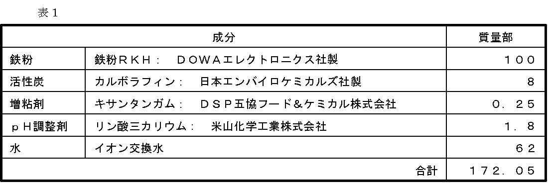
得られた水蒸気発生部121全体を、表3に記載した通気度の第1シート122A、及び第2シート122Bからなる袋体122で被覆し、水蒸気発生体120を作製した。具体的には、水蒸気発生体120の第1シート122A(以下同じ)として、TMS不織布(サーマルボンド(PET/PE)-メルトブローン(ポリプロピレン)-スパンボンド(ポリプロピレン)積層一体型、坪量50g/m2、株式会社クラレ製)を2層積層し、通気度0秒/100mlのシートとした。水蒸気発生体120の第2シート122B(以下同じ)として、ポリエチレン100質量%のフィルムとパルプシートとをラミネートした坪量40g/m2の非通気性シートを使用した。
第1シート122Aと第2シート122Bとの間に水蒸気発生部121を配置して、周縁部を密閉シールし、水蒸気発生体120を得た。このとき、水蒸気発生部121の基材層121Bは、第2シート122B側に配置された。この際、通気面とシール部を含めた第1シート122Aの面積は39.7cm2(6.3cm×6.3cm)であった。
水蒸気発生体120は、後述する評価を実施するまで、酸素遮断袋に入れて保存した。 <Preparation of
The obtained water
The water
The
マスク110を構成するマスク本体部101のシートとして、SMS不織布(スパンボンド(ポリプロピレン)-メルトブローン(ポリプロピレン)-スパンボンド(ポリプロピレン)積層一体型、坪量50g/m2)が外側、坪量25gのスパンボンド不織布(ポリプロピレン)が内側(着用者側)となるように2層を重ねた。この際の、マスク本体部101の0.3μm以上粒子の遮断率は25%であった。マスク本体部101の縦中心の折り畳み線103を挟んで両側の上方に1つずつ(計2つ)、収容体104のマスク上部以外を熱融着し、水蒸気発生体120を収容する収容体104を作製した。マスク本体部101の端部に伸縮性のあるゴム紐状の耳掛け部102を取り付け、立体形状となるマスク110を作製した。マスク本体部101の通気抵抗を収容体部分で計測したところ148Pa/30mmΦ・圧差であった。なお、下記評価においては、収容体104に水蒸気発生体120を各1つずつ(計2つ)、マスク本体部101の2枚の不織布が熱融着されていないマスク110の上側から入れ、マスク本体部101の折り畳み線103近傍及びマスク本体部101の上端部近傍(鼻脇)に、左右対称に一対の水蒸気発生体120をとりつけ、蒸気温熱マスク100とした。
本実施例において、マスク本体部101の着用者側の面全体の面積は、以下の方法にて算出した。
マスク本体部101を中央部で縦方向に折り畳み、上下の最も離間した点を結んだ線(A線)から垂直に先端部方向に最も離れた折り畳み線上の点でシール部の耳掛け側端部をマスク先端とし、当該マスク先端を通る前記A線と平行な線(B線)からから耳掛け方向に7cm平行離間した線(C線)で切り取り、さらにシール部を切り取った。切り取ったマスク本体の片面をA4紙(トッパンフォームズ社製、リサイクルカット判G80A4W、坪量64g/m2、21.0cm×29.7cm:面積623.7cm2)に外周をトレースし、その外周部をハサミで切り取り、切り取った紙の質量を計測した。A4紙の全質量と切り取った紙の質量の2倍量、及びA4紙の全面積から換算したところ、マスク本体部101の着用者側の面全体の面積は152.0cm2であり、マスク本体部101の着用者側の面全体の面積に対する水蒸気発生体120の左右2個分の面積比は52%であった。 <Manufacture of steam
As a sheet of the
In this example, the area of the entire wearer side surface of the
The
水蒸気発生体120の第1シート122Aとして、通気度4.0秒/100ml、坪量40g/m2(商品名:イレブンMOA、東海パルプ社製)の合成パルプ紙を使用し、当該合成パルプ紙を実施例A2においては1枚、実施例A3においては2枚重ねた。それ以外は、実施例A1と同じ方法で蒸気温熱マスク100を作製した。 (Examples A2 and A3)
As the
水蒸気発生体120の第1シート122Aとして、表3に記載の通気度を有する、坪量50g/m2(商品名:TSF-EU、株式会社興人社製)の炭酸カルシウム含有ポリエチレンフィルムを使用した以外は、実施例A1と同じ方法で蒸気温熱マスク100を作製した。 (Examples A4 to A8)
As the
水蒸気発生体120の第2シート122Bとして、表3に記載の通気度を有する、坪量50g/m2(商品名:TSF-EU、株式会社興人社製)の炭酸カルシウム含有ポリエチレンフィルムを使用した以外は、実施例A1と同じ方法で蒸気温熱マスク100を作製した。 (Examples A9 to A11)
As the
実施例A1の水蒸気発生部121(4.9cm×4.9cm;面積24.0cm2)を3.3cm×3.3cm(面積10.9cm2)の大きさに切断したものを水蒸気発生部として使用した。また、水蒸気発生体の作製において、第1シートと第2シートの大きさを、実施例A12では4.8cm×4.8cm(面積23.0cm2)、実施例A13では5.5cm×5.5cm(面積30.3cm2)、比較例A1では3.9cm×3.9cm(面積15.2cm2)とし、それぞれのシートの間に水蒸気発生部121を配置して、周縁部を密閉シールし、水蒸気発生体120を得た。それ以外については、実施例A1と同じ方法で蒸気温熱マスク100を作製することにより、マスク本体部101の着用者側の面全体の面積に対する水蒸気発生体120の面積比を、表3に記載のものとした。 (Examples A12, A13 and Comparative Example A1)
The water vapor generating part 121 (4.9 cm × 4.9 cm; area 24.0 cm 2 ) of Example A1 cut into a size of 3.3 cm × 3.3 cm (area 10.9 cm 2 ) was used as the water vapor generating part. used. In the production of the water vapor generator, the sizes of the first sheet and the second sheet are 4.8 cm × 4.8 cm (area 23.0 cm 2 ) in Example A12 and 5.5 cm × 5. 5 in Example A13. 5 cm (area 30.3cm 2), and Comparative example A1 in 3.9 cm × 3.9 cm (area 15.2 cm 2), by placing the
水蒸気発生部121の作製において、発熱組成物を基材層121Bの片面にダイコーティングする際、水蒸気発生部121の1個の大きさを、実施例A14では4.9cm×6.5cm(面積31.9cm2)、実施例A15では4.9cm×7.5cm(面積36.8cm2)、比較例A2では4.9cm×8.5cm(面積41.7cm2)とし、発熱組成物の塗布量が実施例A1のものと同じ厚み(4.9cm×4.9cm当たりに換算すると1.4g)となるように作製した。また、水蒸気発生体の作製において、第1シートと第2シートの大きさを、実施例A14では6.3cm×8.4cm(面積52.9cm2)、実施例A15では6.3cm×9.6cm(面積60.5cm2)、比較例A2では6.4cm×10.6cm(面積67.8cm2)とし、それぞれのシートの間に水蒸気発生部121を配置して、周縁部を密閉シールし、水蒸気発生体120を得た。それ以外については、実施例A1と同じ方法で蒸気温熱マスク100を作製することにより、マスク本体部101の着用者側の面全体の面積に対する水蒸気発生体120の面積比を、表3に記載のものとした。 (Examples A14 and A15 and Comparative Example A2)
In the production of the water
水蒸気発生部として、実施例A1で使用した水蒸気発生部121を1層のみ用い、また、表3に示される通気度の第1シートを使用した以外は、実施例A1に準じて水蒸気発生体120を作製した。実施例A16については、それ以外は実施例A1と同じ方法で蒸気温熱マスク100を作製し、実施例A17については、蒸気温熱マスク作製の際に、作製した水蒸気発生体加え、水蒸気発生体の第2シートに接するように63mm角の大きさに切り取ったADVANTEC(登録商標)定性濾紙No.2を1枚積層して、蒸気温熱マスク100を作製した。 (Examples A16 and A17)
As the water vapor generating part, only one layer of the water
水蒸気発生部として、表2に示す組成の紛体状の発熱組成物を、次の手順で作製した。
窒素気流下で、鉄粉、水、食塩、吸水ポリマー及び活性炭を均一になるまで混合し、紛体状の水蒸気発生部を作製した。水蒸気発生体120の作製において、実施例A18については実施例A1、実施例A19については実施例A8におけるシート状の水蒸気発生部121に替えて、それぞれ前記粉体状の水蒸気発生部2.8gを使用した以外は、実施例A1と同じ方法で蒸気温熱マスク100を作製した。 (Examples A18 and A19)
As the water vapor generating part, a powdery exothermic composition having the composition shown in Table 2 was prepared by the following procedure.
Under a nitrogen stream, iron powder, water, sodium chloride, a water-absorbing polymer and activated carbon were mixed until uniform to produce a powdery water vapor generating part. In the production of the
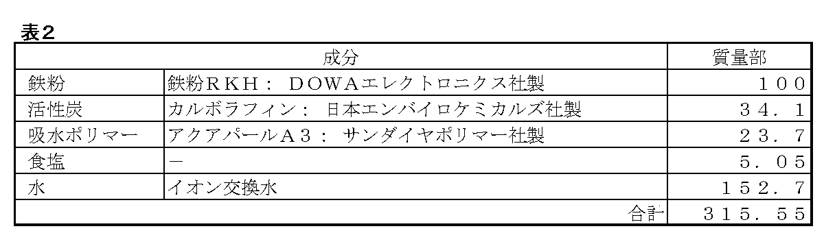
水蒸気発生体120の第1シート122Aとして、坪量50g/m2、TSF-EU、株式会社興人社製の炭酸カルシウム含有ポリエチレンフィルムを使用し、比較例A3については通気度8000秒/100ml、比較例A4については通気度10000秒/100mlのフィルムを用いた以外は、実施例A1と同じ方法で蒸気温熱マスク100を作製した。 (Comparative Examples A3 and A4)
As the
テンシロン万能試験機(ORIENTEC RTC-1150A)を用いて、マスクセットの曲げ剛性値を測定した。マスク本体の折り畳み線を切り取ってマスク片側を用い、水蒸気発生体1セルをマスク収容体に挿入した状態で曲げ剛性値を計測した。測定条件は、スパン間距離30mmで水蒸気発生体を支え、幅60mm、先端半径5mmの板状の押圧部材にて、試験片(水蒸気発生体)の中央部にクロスヘッドスピード20mm/minで負荷を与えた。この時のピーク荷重(3回計測の平均値)を剛性値とした。 [Measurement of stiffness value of water vapor generator]
The bending rigidity value of the mask set was measured using a Tensilon universal testing machine (ORIENTEC RTC-1150A). The bending rigidity value was measured in a state in which the folding line of the mask main body was cut out and one side of the mask was used and one cell of the water vapor generator was inserted into the mask container. The measurement condition is that the steam generator is supported at a span distance of 30 mm, and a load is applied to the center of the test piece (steam generator) at a crosshead speed of 20 mm / min with a plate-like pressing member having a width of 60 mm and a tip radius of 5 mm. Gave. The peak load at this time (average value of three measurements) was taken as the rigidity value.
内容積が4.2リットル、内部の湿度が1RH%以下であり、密閉系内に2.1リットル/minの乾燥空気を供給可能な試験機を準備し、その内部に水蒸気が蒸散可能なように所定寸法の水蒸気発生体120を静置して発熱させる。そして、前記密閉系外に排出される空気の湿度を湿度計で測定し、下記式(1)を用いて発熱開始後に発生する水蒸気の量を求め、単位時間当たりの水蒸気量とした。eは水蒸気圧(Pa)、esは飽和水蒸気圧(Pa:JIS Z8806より引用)、Tは温度(℃:乾球温度)、sはサンプリング周期(秒)である。 [Measurement of water vapor generation (water vapor generator)]
A tester with an internal volume of 4.2 liters and an internal humidity of 1 RH% or less and capable of supplying 2.1 liters / min of dry air in a closed system is prepared so that water vapor can evaporate inside. The
絶対湿度D(g/m3)=(0.794×10-2×e)/(1+0.00366T)
=(0.794×10⁻²×U×es)/〔100×(1+0.00366T)〕
単位空気容積P(リットル)=(2.1×s)/60
単位時間当たりの水蒸気の発生量A(g)=(P×D)/1000・・・(1) Relative humidity U (% RH) = (e / es) × 100
Absolute humidity D (g / m 3 ) = (0.794 × 10 −2 × e) / (1 + 0.00366T)
= (0.794 × 10 −2 × U × es) / [100 × (1 + 0.00366T)]
Unit air volume P (liter) = (2.1 × s) / 60
Amount of water vapor generated per unit time A (g) = (P × D) / 1000 (1)
20℃60%RHの環境下、有限会社デジタルヒューマンテクノロジー社の男性人頭データ(日本人成人男性52名平均)を用い作製した頭部模型マネキン(以下「マネキン」)にマスクを装着してから30分後に、マスク本体より水蒸気発生体を取り出し、注射器にて水蒸気発生体内部(肌側シートと外側シートで閉じられた内部)の気体を吸引し、体積を測定した。2回測定を行い、その平均をもって測定値とした。 [Swelling of steam heating element]
After wearing a mask on a head model mannequin (hereinafter referred to as “mannequin”) created using male human head data (average of 52 Japanese adult males) of Digital Human Technology Co., Ltd. in an environment of 20 ° C. and 60% RH After 30 minutes, the water vapor generator was taken out from the mask body, and the gas inside the water vapor generator (inside closed by the skin side sheet and the outer sheet) was sucked with a syringe, and the volume was measured. Two measurements were taken and the average was taken as the measurement value.
水蒸気発生体に対して行った前述の水蒸気発生量の測定方法にて、水蒸気発生量の測定を行った。 [Measurement of water vapor generation (steam thermal mask)]
The amount of water vapor generation was measured by the method for measuring the amount of water vapor generation performed on the water vapor generator.
マスク本体部101の通気抵抗はマスクテスターMTS-2(柴田科学)を用いて、測定を行った。マスクテスターMTS-2(柴田科学製)の本体上部に、マスク本体部101のシート材から3.5cm×3.5~5cm×5cmのサイズに切り出したシートを配置し、シート固定用治具で、漏れがないように固定した。測定は、試験面積は、7cm2(3cmΦ)、試験流量10L/min.で行い、10秒間測定した。通気抵抗は、シートへの空気流入側(入口側)と空気流出側(出口側)との差圧から求めたところ、148Paであった。 [Measurement of Ventilation Resistance of Mask Body 101]
The airflow resistance of the
20℃60%RHの環境下、マネキンの鼻下部に、温湿度計(センシリオン社製SHT75)を取り付け、頭部模型の鼻部よりベンチレーター(HARVARD APPARATUS DUAL PHASE CONTROL RESPIRATOR(HARVARD APPARATUS社製))を用いて、人の呼吸リズムを模して、1分間に15回、1回あたり500mlの頻度で吸気を行った。この状態で、蒸気温熱マスク100をマネキンに装着し、温湿度変化を計測した。温度と相対湿度より、絶対湿度を算出し、10分間の最大絶対湿度と平均絶対湿度を求めた。 [Measurement of absolute humidity in the mask]
A thermohygrometer (SHT75 manufactured by Sensirion Co., Ltd.) is attached to the lower nose of the mannequin in an environment of 20 ° C. and 60% RH. Inhalation was performed at a frequency of 500 ml per time, 15 times per minute, imitating a human breathing rhythm. In this state, the steam
22℃の環境において、男性5名のパネラーにてマスクの装着感を評価した。マスクを装着した状態での温感、持続性、蒸気感(潤い感)及び息苦しさを以下の基準で評価し、最も人数の多い点数を選びスコア化した。 [Evaluation of wearing feeling of mask (warmth, sustainability, feeling of steam (moisturation), breathing difficulty)]
In a 22 ° C. environment, the mask wearing feeling was evaluated by five male panelists. The warmth, sustainability, steaminess (moistness) and breathlessness with the mask attached were evaluated according to the following criteria, and the score with the largest number of people was selected and scored.
1:マスク本体のみに比べ、温かさの差を感じにくい
2:マスク本体のみに比べ、温かい
3:マスク本体のみに比べ、十分温かく適度な温感
4:マスク本体のみに比べ、十分温かいがやや熱い
5:マスク本体のみに比べ、十分温かいが熱い Warm feeling 1: Difficult to feel the difference in warmth compared to the mask body only 2: Warm compared to the mask body only 3: Warm enough and moderate compared to the mask body only 4: Warm enough compared to the mask body alone Slightly hot 5: Warm enough but hot compared to the mask itself
1:快適な温感及び蒸気感の持続時間が5分未満
2:快適な温感及び蒸気感の持続時間が5分以上10分未満
3:快適な温感及び蒸気感の持続時間が10分以上 Sustainability 1: Duration of comfortable warm feeling and steam feeling is less than 5 minutes 2: Duration of comfortable warm feeling and steam feeling is 5 minutes or more and less than 10 minutes 3: Duration of comfortable warm feeling and steam feeling 10 minutes or more
1:マスク本体のみに比べ、喉や鼻の粘膜に潤いの差を感じにくい
2:マスク本体のみに比べ、喉や鼻の粘膜にやや潤いを感じる
3:マスク本体のみに比べ、喉や鼻の粘膜に潤いを感じる
4:マスク本体のみに比べ、喉や鼻の粘膜の潤い感が優れる
5:マスク本体のみに比べ、喉や鼻の粘膜の潤い感が非常に優れる Steam feeling (moist feeling)
1: Difficult to feel moisture difference in throat and nose mucosa compared to mask body only 2: Compared to mask body alone, feels slightly moistened in throat and nose mucosa 3: Compared to mask body only, throat and nose Moisture is felt in the mucous membrane 4: Moisture sensation in the throat and nasal mucosa is superior to the mask body only 5: Moisture sensation in the throat and nasal mucosa is superior compared to the mask body alone
1:マスク本体に比べ、ひどく息苦しい
2:マスク本体に比べ、かなり息苦しい
3:マスク本体に比べ、少し息苦しさを感じる
4:マスク本体に比べ、ほとんど息苦しさを感じない
5:マスク本体と同等で、全く息苦しさを感じない Breathing 1: Slightly suffocating compared to the mask body 2: Slightly suffocating compared to the mask body 3: Slightly suffocating compared to the mask body 4: Slightly suffocating compared to the mask body 5: With the mask body Equivalent, no stuffyness

(実施例B1)
上記実施例Aと同様の形状の蒸気温熱マスク100を作製した。具体的には以下のとおりである。
<水蒸気発生部121の作製>
表1に示す組成の発熱組成物を用い、上記実施例A1と同様の方法により、水蒸気発生部121を作製した。 [Example B]
(Example B1)
A vapor
<Preparation of water
Using the exothermic composition having the composition shown in Table 1, a water
得られた水蒸気発生部121全体を、表4に記載した通気度の第1シート122A、及び第2シート122Bからなる袋体122で被覆し、水蒸気発生体120を作製した。具体的には、水蒸気発生体120の第1シート122A(以下同じ)として、TMS不織布(サーマルボンド(PET/PE)-メルトブローン(ポリプロピレン)-スパンボンド(ポリプロピレン)積層一体型、坪量50g/m2、株式会社クラレ製)を2層に積層し、通気度0秒/100mlのシートとした。水蒸気発生体120の第2シート122B(以下同じ)として、通気度7000秒/100ml、坪量50g/m2(商品名:TSF-EU、株式会社興人社製)の炭酸カルシウム含有ポリエチレンフィルムを使用した。第1シート122Aと第2シート122Bとの間に水蒸気発生部121を配置して、周縁部を密閉シールし、水蒸気発生体120を得た。このとき、水蒸気発生部121の基材層121Bは、第2シート122B側に配置された。この際、通気面(第1シート122A)の面積が6.3cm×6.3cm(面積39.7cm2)となるようにした(通気面の面積に占める水蒸気発生部121の面積率は60.5%)。
水蒸気発生体120は、後述する評価を実施するまで、酸素遮断袋に入れて保存した。 <Preparation of
The obtained water
The
前記実施例A1と同様の方法にて蒸気温熱マスク100を作製した。 <Manufacture of steam
A vapor
水蒸気発生体120の第1シート122Aとして、通気度4.0秒/100ml、坪量40g/m2(商品名:イレブンMOA、東海パルプ社製)の合成パルプ紙を使用し、当該合成パルプ紙を実施例B2においては1枚、実施例B3においては2枚重ねた。それ以外は、実施例B1にと同じ方法で蒸気温熱マスク100を作製した。 (Examples B2 and B3)
As the
水蒸気発生体120の第1シート122Aとして、通気度250秒/100ml、坪量50g/m2(商品名:TSF-EU、株式会社興人社製)の炭酸カルシウム含有ポリエチレンフィルムを使用した。それ以外は、実施例B1と同じ方法で蒸気温熱マスク100を作製した。 (Example B4)
As the
水蒸気発生体120の第2シート122Bとして、表4に記載の通気度を有する、坪量50g/m2(商品名:TSF-EU、株式会社興人社製)の炭酸カルシウム含有ポリエチレンフィルムを使用した以外は、実施例B1と同じ方法で蒸気温熱マスク100を作製した。 (Examples B5 to B9)
As the
実施例B1の水蒸気発生部121(4.9cm×4.9cm;面積24.0cm2)を3.3cm×3.3cm(面積10.9cm2)の大きさに切断したものを水蒸気発生部として使用した。また、水蒸気発生体の作製において、第1シートと第2シートの大きさを、実施例B10では4.8cm×4.8cm(面積23.0cm2)、実施例B11では5.5cm×5.5cm(面積30.3cm2)、比較例B1では3.9cm×3.9cm(面積15.2cm2)とし、それぞれのシートの間に水蒸気発生部121を配置して、周縁部を密閉シールし、水蒸気発生体120を得た。それ以外については、実施例B1と同じ方法で蒸気温熱マスク100を作製することにより、マスク本体部101の着用者側の面全体の面積に対する水蒸気発生体120の面積比を、表4に記載のものとした。 (Examples B10 and B11 and Comparative Example B1)
The water vapor generating part 121 (4.9 cm × 4.9 cm; area 24.0 cm 2 ) of Example B1 cut into a size of 3.3 cm × 3.3 cm (area 10.9 cm 2 ) was used as the water vapor generating part. used. In the production of the water vapor generator, the sizes of the first sheet and the second sheet were 4.8 cm × 4.8 cm (area 23.0 cm 2 ) in Example B10 and 5.5 cm × 5. 5 in Example B11. 5 cm (area 30.3cm 2), and Comparative example B1 in 3.9 cm × 3.9 cm (area 15.2 cm 2), by placing the
水蒸気発生部121の作製において、発熱組成物を基材層121Bの片面にダイコーティングする際、水蒸気発生部121の1個の大きさを、実施例B12では4.9cm×6.5cm(面積31.9cm2)、実施例B13では4.9cm×7.5cm(面積36.8cm2)、比較例B2では4.9cm×8.5cm(面積41.7cm2)とし、発熱組成物の塗布量が実施例B1のものと同じ厚み(4.9cm×4.9cm当たりに換算すると1.4g)となるように作製した。また、水蒸気発生体の作製において、第1シートと第2シートの大きさを、実施例B12では6.3cm×8.4cm(面積52.9cm2)、実施例B13では6.3cm×9.6cm(面積60.5cm2)、比較例B2では6.4cm×10.6cm(面積67.8cm2)とし、それぞれのシートの間に水蒸気発生部121を配置して、周縁部を密閉シールし、水蒸気発生体120を得た。それ以外については、実施例B1と同じ方法で蒸気温熱マスク100を作製することにより、マスク本体部101の着用者側の面全体の面積に対する水蒸気発生体120の面積比を、表4に記載のものとした。 (Examples B12, B13 and Comparative Example B2)
In the production of the water
水蒸気発生部として、実施例B1で使用した水蒸気発生部121を1層のみ用い、また、表4に示される通気度の第1シートを使用した以外は、実施例B1に準じて水蒸気発生体120を作製した。実施例B14については、それ以外は実施例B1と同じ方法で準じて蒸気温熱マスク100を作製し、実施例B15については、蒸気温熱マスク作製の際に、作製した水蒸気発生体加え、水蒸気発生体の第2シートに接するように63mm角の大きさに切り取ったADVANTEC(登録商標)定性濾紙No.2を1枚積層して、蒸気温熱マスク100を作製した。 (Examples B14 and B15)
As the water vapor generating part, only one layer of the water
水蒸気発生部として、表2に示す組成の紛体状の発熱組成物を、次の手順で作製した。
窒素気流下で、鉄粉、水、食塩、吸水ポリマー及び活性炭を均一になるまで混合し、紛体状の水蒸気発生部を作製した。水蒸気発生体120の作製において、実施例B1におけるシート状の水蒸気発生部121に替えて、前記粉体状の水蒸気発生部2.8gを使用した以外は、実施例B1と同じ方法で蒸気温熱マスク100を作製した。 (Example B16)
As the water vapor generating part, a powdery exothermic composition having the composition shown in Table 2 was prepared by the following procedure.
Under a nitrogen stream, iron powder, water, sodium chloride, a water-absorbing polymer and activated carbon were mixed until uniform to produce a powdery water vapor generating part. In the production of the
水蒸気発生体120の第1シート122A及び第2シート122Bとして、表4に示した通気度、坪量50g/m2、TSF-EU、株式会社興人社製の炭酸カルシウム含有ポリエチレンフィルムを使用した以外は、実施例B1と同じ方法で蒸気温熱マスク100を作製した。 (Comparative Examples B3 and B4)
As the
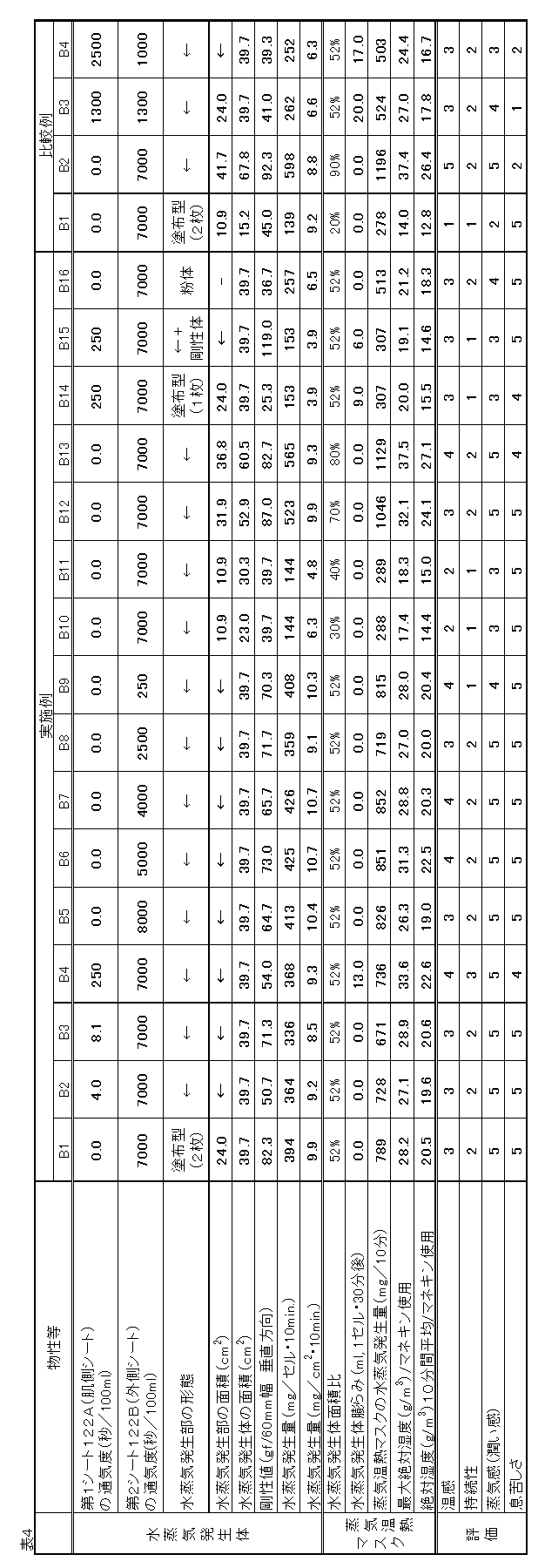
Claims (5)
- 着用時に着用者の鼻と口とを覆うマスク本体部と、前記マスク本体部の左右両端に設けられた一対の耳掛け部と、を備えたマスクと、
前記マスク本体部に水蒸気発生体と、を備えた蒸気温熱マスクであって、
前記マスク本体部の前記着用者側の面全体の面積に対する、前記水蒸気発生体の占める面積の割合が30%以上80%以下であり、
前記水蒸気発生体は内部に水蒸気発生部を収容するものであり、
前記水蒸気発生体は、前記水蒸気発生部の前記着用者側の面に第1シート、前記水蒸気発生部の着用者側の前記面と反対側の面に第2シートを備え、
前記第1シートの通気度が7000秒/100ml以下であり、
前記第2シートの通気度が8000秒/100ml超である、
蒸気温熱マスク。 A mask provided with a mask main body that covers the nose and mouth of the wearer when worn, and a pair of ear hooks provided at the left and right ends of the mask main body,
A steam thermal mask comprising a steam generator in the mask body,
The ratio of the area occupied by the water vapor generator to the area of the entire wearer-side surface of the mask body is 30% or more and 80% or less,
The water vapor generator contains a water vapor generating part inside,
The water vapor generator comprises a first sheet on the wearer side surface of the water vapor generation unit, and a second sheet on the surface opposite to the wearer side surface of the water vapor generation unit,
The air permeability of the first sheet is 7000 seconds / 100 ml or less,
The air permeability of the second sheet is more than 8000 sec / 100 ml,
Steam thermal mask. - 着用時に着用者の鼻と口とを覆うマスク本体部と、前記マスク本体部の左右両端に設けられた一対の耳掛け部と、を備えたマスクと、
前記マスク本体部に水蒸気発生体と、を備えた蒸気温熱マスクであって、
前記マスク本体部の前記着用者側の面全体の面積に対する、前記水蒸気発生体の占める面積の割合が30%以上80%以下であり、
前記水蒸気発生体は内部に水蒸気発生部を収容するものであり、
前記水蒸気発生体は、前記水蒸気発生部の前記着用者側の面に第1シート、前記水蒸気発生部の着用者側の前記面と反対側の面に第2シートを備え、
前記第2シートの通気度が250秒/100ml以上8000秒/100ml以下であり、
前記第1シートの通気度が前記第2シートの通気度に対して20%以下である、
蒸気温熱マスク。 A mask provided with a mask main body that covers the nose and mouth of the wearer when worn, and a pair of ear hooks provided at the left and right ends of the mask main body,
A steam thermal mask comprising a steam generator in the mask body,
The ratio of the area occupied by the water vapor generator to the area of the entire wearer-side surface of the mask body is 30% or more and 80% or less,
The water vapor generator contains a water vapor generating part inside,
The water vapor generator comprises a first sheet on the wearer side surface of the water vapor generation unit, and a second sheet on the surface opposite to the wearer side surface of the water vapor generation unit,
The air permeability of the second sheet is 250 seconds / 100 ml or more and 8000 seconds / 100 ml or less,
The air permeability of the first sheet is 20% or less with respect to the air permeability of the second sheet,
Steam thermal mask. - 前記水蒸気発生体の垂直方向の剛性値が30gf/60mm幅以上である、請求項1または2に記載の蒸気温熱マスク。 The steam thermal mask according to claim 1 or 2, wherein the steam generator has a vertical rigidity value of 30 gf / 60 mm width or more.
- 前記蒸気温熱マスクの使用中におけるマスク内の絶対湿度の最大値が12g/m3以上50g/m3以下である、請求項1乃至3のいずれか一項に記載の蒸気温熱マスク。 The steam thermal mask according to any one of claims 1 to 3, wherein a maximum value of absolute humidity in the mask during use of the steam thermal mask is 12 g / m 3 or more and 50 g / m 3 or less.
- 前記マスク本体部の通気抵抗が5Pa以上200Pa以下である、請求項1乃至4のいずれか一項に記載の蒸気温熱マスク。 The steam thermal mask according to any one of claims 1 to 4, wherein a ventilation resistance of the mask main body is 5 Pa or more and 200 Pa or less.
Priority Applications (12)
| Application Number | Priority Date | Filing Date | Title |
|---|---|---|---|
| EP20204937.5A EP3791835A1 (en) | 2015-06-10 | 2015-06-10 | Steam heating mask |
| JP2017523026A JP6393832B2 (en) | 2015-06-10 | 2015-06-10 | Steam thermal mask |
| US15/580,909 US11045386B2 (en) | 2015-06-10 | 2015-06-10 | Steam heating mask |
| CN202010855425.6A CN111887520B (en) | 2015-06-10 | 2015-06-10 | Steam warm mask |
| CN202010855958.4A CN111887521B (en) | 2015-06-10 | 2015-06-10 | Steam warm mask |
| PCT/JP2015/066743 WO2016199245A1 (en) | 2015-06-10 | 2015-06-10 | Steam heating mask |
| KR1020177037209A KR102306197B1 (en) | 2015-06-10 | 2015-06-10 | Steam heating mask |
| CN201580080790.1A CN107635516B (en) | 2015-06-10 | 2015-06-10 | Steam warm mask |
| EP15894930.5A EP3308754A4 (en) | 2015-06-10 | 2015-06-10 | Steam heating mask |
| RU2018100099A RU2695621C2 (en) | 2015-06-10 | 2015-06-10 | Mask with steam heating |
| SG11201709575RA SG11201709575RA (en) | 2015-06-10 | 2015-06-10 | Steam heating mask |
| US17/327,318 US20210275392A1 (en) | 2015-06-10 | 2021-05-21 | Steam heating mask |
Applications Claiming Priority (1)
| Application Number | Priority Date | Filing Date | Title |
|---|---|---|---|
| PCT/JP2015/066743 WO2016199245A1 (en) | 2015-06-10 | 2015-06-10 | Steam heating mask |
Related Child Applications (2)
| Application Number | Title | Priority Date | Filing Date |
|---|---|---|---|
| US15/580,909 A-371-Of-International US11045386B2 (en) | 2015-06-10 | 2015-06-10 | Steam heating mask |
| US17/327,318 Continuation US20210275392A1 (en) | 2015-06-10 | 2021-05-21 | Steam heating mask |
Publications (1)
| Publication Number | Publication Date |
|---|---|
| WO2016199245A1 true WO2016199245A1 (en) | 2016-12-15 |
Family
ID=57503682
Family Applications (1)
| Application Number | Title | Priority Date | Filing Date |
|---|---|---|---|
| PCT/JP2015/066743 WO2016199245A1 (en) | 2015-06-10 | 2015-06-10 | Steam heating mask |
Country Status (8)
| Country | Link |
|---|---|
| US (2) | US11045386B2 (en) |
| EP (2) | EP3308754A4 (en) |
| JP (1) | JP6393832B2 (en) |
| KR (1) | KR102306197B1 (en) |
| CN (3) | CN107635516B (en) |
| RU (1) | RU2695621C2 (en) |
| SG (1) | SG11201709575RA (en) |
| WO (1) | WO2016199245A1 (en) |
Cited By (5)
| Publication number | Priority date | Publication date | Assignee | Title |
|---|---|---|---|---|
| JP2018117908A (en) * | 2017-01-26 | 2018-08-02 | 花王株式会社 | Steam warming tool and method for using the same |
| CN110769790A (en) * | 2017-06-22 | 2020-02-07 | 花王株式会社 | Warming appliance |
| WO2020240906A1 (en) * | 2019-05-24 | 2020-12-03 | 花王株式会社 | Steam generator |
| CN113349480A (en) * | 2020-03-04 | 2021-09-07 | 浙江珍珠生活科技有限公司 | Pearl antibacterial non-woven medical protective mask and preparation method thereof |
| WO2022259588A1 (en) * | 2021-06-08 | 2022-12-15 | 花王株式会社 | Heating implement |
Families Citing this family (11)
| Publication number | Priority date | Publication date | Assignee | Title |
|---|---|---|---|---|
| USD949325S1 (en) * | 2018-07-11 | 2022-04-19 | 3M Innovative Properties Company | Respirator |
| JP7321706B2 (en) * | 2018-12-28 | 2023-08-07 | 小林製薬株式会社 | mask |
| JP7325958B2 (en) * | 2018-12-28 | 2023-08-15 | 小林製薬株式会社 | mask |
| CN110025066B (en) * | 2019-03-07 | 2020-10-30 | 泉州台商投资区钰宝商贸有限公司 | Intelligent wearable device for detecting amount of exercise and body state |
| KR102022669B1 (en) * | 2019-06-21 | 2019-09-18 | 박민규 | Eye moisturizer |
| JP2021006667A (en) * | 2019-06-28 | 2021-01-21 | 小林製薬株式会社 | mask |
| KR102105699B1 (en) | 2020-01-20 | 2020-04-28 | 김대혁 | Mask type Moisture Pack |
| CN113521581A (en) * | 2020-04-15 | 2021-10-22 | 咏达生医材料股份有限公司 | Air supply port cover |
| CN115190789A (en) | 2020-04-24 | 2022-10-14 | 花王株式会社 | Warming appliance |
| WO2021222435A1 (en) * | 2020-04-29 | 2021-11-04 | Mark Silverberg | Medical heated face mask |
| TWI749893B (en) * | 2020-11-23 | 2021-12-11 | 台覲實業股份有限公司 | Cloth mask manufacturing method |
Citations (9)
| Publication number | Priority date | Publication date | Assignee | Title |
|---|---|---|---|---|
| JPH11137618A (en) * | 1997-11-04 | 1999-05-25 | Nikkiso Ysi Kk | Incubator |
| JP2001029493A (en) * | 1999-07-16 | 2001-02-06 | Kanai Hiroaki | Steam preventer for mask |
| JP2006102145A (en) * | 2004-10-05 | 2006-04-20 | Uni Charm Corp | Mask |
| JP2007289682A (en) * | 2006-03-31 | 2007-11-08 | Kao Corp | Steam generator for eye |
| JP2010051690A (en) * | 2008-08-29 | 2010-03-11 | Kao Corp | Heating implement |
| JP2011188947A (en) * | 2010-03-12 | 2011-09-29 | Kao Corp | Steam generator |
| JP2011206222A (en) * | 2010-03-29 | 2011-10-20 | Kao Corp | Moisture generating instrument |
| JP2012020175A (en) * | 2011-10-17 | 2012-02-02 | Kao Corp | Mask |
| JP2014140774A (en) * | 2014-05-12 | 2014-08-07 | Kobayashi Pharmaceutical Co Ltd | Mask |
Family Cites Families (35)
| Publication number | Priority date | Publication date | Assignee | Title |
|---|---|---|---|---|
| US4225542A (en) * | 1978-12-12 | 1980-09-30 | Minnesota Mining And Manufacturing Company | Evaporative humidifier |
| US5154984A (en) * | 1986-10-09 | 1992-10-13 | Sumitomo Metal Industries, Ltd. | Metal-ceramic composite |
| US4947924A (en) * | 1987-04-10 | 1990-08-14 | Sumitomo Metal Industries, Ltd. | Metal-ceramic composite and method of producing the same |
| JP3049707B2 (en) * | 1998-04-03 | 2000-06-05 | 花王株式会社 | Steam generator |
| JP4418906B2 (en) | 1999-04-02 | 2010-02-24 | 興研株式会社 | Dust mask filter |
| JP2001299916A (en) * | 2000-04-18 | 2001-10-30 | Kao Corp | Mask-shaped inhalator |
| US20040112366A1 (en) * | 2001-03-16 | 2004-06-17 | The Procter & Gamble Company | Thermal device |
| DE10139881B4 (en) * | 2001-08-20 | 2017-06-08 | Resmed R&D Germany Gmbh | Apparatus for supplying a breathing gas and method for controlling the same |
| JP2003102761A (en) | 2001-09-28 | 2003-04-08 | Kao Corp | Method of manufacturing heating compact |
| JP4093348B2 (en) * | 2002-05-20 | 2008-06-04 | マイコール株式会社 | Foot temperature heating element and method of manufacturing the foot temperature heating element |
| JP3901660B2 (en) | 2002-06-20 | 2007-04-04 | 花王株式会社 | Steam generator |
| JP2004208978A (en) * | 2002-12-27 | 2004-07-29 | Mycoal Products Corp | Heating composition and heating body |
| JP2004321737A (en) * | 2003-04-23 | 2004-11-18 | Daihachi Matsuura | Steam mask |
| JP4223329B2 (en) * | 2003-06-09 | 2009-02-12 | ユニ・チャーム株式会社 | Humidifier for face wearing |
| CN1829487B (en) * | 2003-07-31 | 2010-05-05 | 花王株式会社 | Warming tool in a sheet form |
| US6974470B2 (en) * | 2004-02-27 | 2005-12-13 | Kao Corporation | Heat-generative, steam generation sheet for face |
| FR2875138B1 (en) * | 2004-09-15 | 2008-07-11 | Mallinckrodt Dev France Sa | CONTROL METHOD FOR A HEATING HUMIDIFIER |
| EP3034053B1 (en) * | 2005-03-04 | 2019-04-24 | Kao Corporation | Moist heating device |
| EP2002813B1 (en) * | 2006-03-31 | 2018-07-18 | Kao Corporation | Water vapor generator |
| US8394134B2 (en) * | 2007-02-16 | 2013-03-12 | Kao Corporation | Heat generating device |
| JP2008295961A (en) * | 2007-06-04 | 2008-12-11 | Kobayashi Pharmaceut Co Ltd | Mask |
| JP2009000200A (en) | 2007-06-20 | 2009-01-08 | Meiko Shoji Kk | Disposable three-dimensional mask, disposable three-dimensional mask enclosed body and heating sheet for disposable three-dimensional mask |
| JP5284700B2 (en) * | 2007-11-09 | 2013-09-11 | 花王株式会社 | Heating tool |
| US9802022B2 (en) * | 2008-03-06 | 2017-10-31 | Resmed Limited | Humidification of respiratory gases |
| CN113425974A (en) * | 2008-03-06 | 2021-09-24 | 瑞思迈私人有限公司 | Humidification of respiratory gases |
| JP5268432B2 (en) | 2008-05-30 | 2013-08-21 | 小林製薬株式会社 | Absorbent core and mask containing the same |
| FR2935272B1 (en) * | 2008-08-26 | 2010-09-03 | Deltalyo & Valmy | MULTILAYER COMPOSITION FOR RESPIRATORY MASK |
| WO2010067761A1 (en) * | 2008-12-10 | 2010-06-17 | 花王株式会社 | Heat generating implement |
| JP5734843B2 (en) * | 2009-04-06 | 2015-06-17 | 株式会社Tkb | Artificial nose and breathing circuit having the artificial nose |
| US8365771B2 (en) | 2009-12-16 | 2013-02-05 | 3M Innovative Properties Company | Unidirectional valves and filtering face masks comprising unidirectional valves |
| JP2011136060A (en) * | 2009-12-28 | 2011-07-14 | Kao Corp | Nasal region heating implement for mask |
| RU2582454C2 (en) * | 2010-06-09 | 2016-04-27 | Као Корпорейшн | Steam-generative warming device |
| EP2796117B1 (en) | 2011-12-21 | 2016-11-09 | Kao Corporation | Vapor heating implement |
| US9615612B2 (en) | 2013-08-29 | 2017-04-11 | 3M Innovative Properties Company | Filtering face-piece respirator with stiffening member integral with filtering structure |
| CN104510031A (en) | 2014-12-26 | 2015-04-15 | 王彤 | Humidifying piece and humidifying mask with same |
-
2015
- 2015-06-10 CN CN201580080790.1A patent/CN107635516B/en active Active
- 2015-06-10 EP EP15894930.5A patent/EP3308754A4/en active Pending
- 2015-06-10 JP JP2017523026A patent/JP6393832B2/en active Active
- 2015-06-10 RU RU2018100099A patent/RU2695621C2/en active
- 2015-06-10 US US15/580,909 patent/US11045386B2/en active Active
- 2015-06-10 SG SG11201709575RA patent/SG11201709575RA/en unknown
- 2015-06-10 KR KR1020177037209A patent/KR102306197B1/en active IP Right Grant
- 2015-06-10 CN CN202010855425.6A patent/CN111887520B/en active Active
- 2015-06-10 EP EP20204937.5A patent/EP3791835A1/en not_active Withdrawn
- 2015-06-10 WO PCT/JP2015/066743 patent/WO2016199245A1/en active Application Filing
- 2015-06-10 CN CN202010855958.4A patent/CN111887521B/en active Active
-
2021
- 2021-05-21 US US17/327,318 patent/US20210275392A1/en not_active Abandoned
Patent Citations (9)
| Publication number | Priority date | Publication date | Assignee | Title |
|---|---|---|---|---|
| JPH11137618A (en) * | 1997-11-04 | 1999-05-25 | Nikkiso Ysi Kk | Incubator |
| JP2001029493A (en) * | 1999-07-16 | 2001-02-06 | Kanai Hiroaki | Steam preventer for mask |
| JP2006102145A (en) * | 2004-10-05 | 2006-04-20 | Uni Charm Corp | Mask |
| JP2007289682A (en) * | 2006-03-31 | 2007-11-08 | Kao Corp | Steam generator for eye |
| JP2010051690A (en) * | 2008-08-29 | 2010-03-11 | Kao Corp | Heating implement |
| JP2011188947A (en) * | 2010-03-12 | 2011-09-29 | Kao Corp | Steam generator |
| JP2011206222A (en) * | 2010-03-29 | 2011-10-20 | Kao Corp | Moisture generating instrument |
| JP2012020175A (en) * | 2011-10-17 | 2012-02-02 | Kao Corp | Mask |
| JP2014140774A (en) * | 2014-05-12 | 2014-08-07 | Kobayashi Pharmaceutical Co Ltd | Mask |
Non-Patent Citations (1)
| Title |
|---|
| See also references of EP3308754A4 * |
Cited By (8)
| Publication number | Priority date | Publication date | Assignee | Title |
|---|---|---|---|---|
| JP2018117908A (en) * | 2017-01-26 | 2018-08-02 | 花王株式会社 | Steam warming tool and method for using the same |
| CN110769790A (en) * | 2017-06-22 | 2020-02-07 | 花王株式会社 | Warming appliance |
| WO2020240906A1 (en) * | 2019-05-24 | 2020-12-03 | 花王株式会社 | Steam generator |
| JP2020192310A (en) * | 2019-05-24 | 2020-12-03 | 花王株式会社 | Steam generator |
| JP7309562B2 (en) | 2019-05-24 | 2023-07-18 | 花王株式会社 | steam generator |
| CN113349480A (en) * | 2020-03-04 | 2021-09-07 | 浙江珍珠生活科技有限公司 | Pearl antibacterial non-woven medical protective mask and preparation method thereof |
| WO2022259588A1 (en) * | 2021-06-08 | 2022-12-15 | 花王株式会社 | Heating implement |
| JP7332839B2 (en) | 2021-06-08 | 2023-08-23 | 花王株式会社 | heating tool |
Also Published As
| Publication number | Publication date |
|---|---|
| CN111887520B (en) | 2022-11-11 |
| JP6393832B2 (en) | 2018-09-19 |
| RU2695621C2 (en) | 2019-07-24 |
| EP3791835A1 (en) | 2021-03-17 |
| US11045386B2 (en) | 2021-06-29 |
| CN111887521A (en) | 2020-11-06 |
| JPWO2016199245A1 (en) | 2018-03-29 |
| KR20180017050A (en) | 2018-02-20 |
| KR102306197B1 (en) | 2021-09-28 |
| CN111887520A (en) | 2020-11-06 |
| RU2018100099A (en) | 2019-07-12 |
| EP3308754A4 (en) | 2018-12-12 |
| US20180318166A1 (en) | 2018-11-08 |
| EP3308754A1 (en) | 2018-04-18 |
| SG11201709575RA (en) | 2017-12-28 |
| RU2018100099A3 (en) | 2019-07-17 |
| CN107635516B (en) | 2021-06-08 |
| US20210275392A1 (en) | 2021-09-09 |
| CN107635516A (en) | 2018-01-26 |
| CN111887521B (en) | 2023-04-25 |
Similar Documents
| Publication | Publication Date | Title |
|---|---|---|
| JP6393832B2 (en) | Steam thermal mask | |
| JP6742374B2 (en) | Steam heating mask | |
| JP6997545B2 (en) | Steam heating equipment and how to use it | |
| WO2019176998A1 (en) | Heating tool | |
| JP6859116B2 (en) | Steam heater and how to use it | |
| JP2011136060A (en) | Nasal region heating implement for mask | |
| JP2020114957A (en) | Vapor heating mask | |
| TWI690348B (en) | Steam warming mask | |
| RU2768577C2 (en) | Steam-heated mask | |
| WO2022168435A1 (en) | Mask | |
| WO2022118501A1 (en) | Steam generator | |
| JP2022119177A (en) | mask | |
| CN116829015A (en) | face mask | |
| JP2017169600A (en) | Dry eye improvement tool |
Legal Events
| Date | Code | Title | Description |
|---|---|---|---|
| 121 | Ep: the epo has been informed by wipo that ep was designated in this application |
Ref document number: 15894930 Country of ref document: EP Kind code of ref document: A1 |
|
| ENP | Entry into the national phase |
Ref document number: 2017523026 Country of ref document: JP Kind code of ref document: A |
|
| WWE | Wipo information: entry into national phase |
Ref document number: 11201709575R Country of ref document: SG |
|
| WWE | Wipo information: entry into national phase |
Ref document number: 15580909 Country of ref document: US |
|
| NENP | Non-entry into the national phase |
Ref country code: DE |
|
| ENP | Entry into the national phase |
Ref document number: 20177037209 Country of ref document: KR Kind code of ref document: A |
|
| WWE | Wipo information: entry into national phase |
Ref document number: 2018100099 Country of ref document: RU Ref document number: 2015894930 Country of ref document: EP |