WO2016194677A1 - シール装置および回転機械 - Google Patents
シール装置および回転機械 Download PDFInfo
- Publication number
- WO2016194677A1 WO2016194677A1 PCT/JP2016/065169 JP2016065169W WO2016194677A1 WO 2016194677 A1 WO2016194677 A1 WO 2016194677A1 JP 2016065169 W JP2016065169 W JP 2016065169W WO 2016194677 A1 WO2016194677 A1 WO 2016194677A1
- Authority
- WO
- WIPO (PCT)
- Prior art keywords
- fin
- fixed
- movable
- sealing device
- movable fin
- Prior art date
- Legal status (The legal status is an assumption and is not a legal conclusion. Google has not performed a legal analysis and makes no representation as to the accuracy of the status listed.)
- Ceased
Links
Images




Classifications
-
- F—MECHANICAL ENGINEERING; LIGHTING; HEATING; WEAPONS; BLASTING
- F01—MACHINES OR ENGINES IN GENERAL; ENGINE PLANTS IN GENERAL; STEAM ENGINES
- F01D—NON-POSITIVE DISPLACEMENT MACHINES OR ENGINES, e.g. STEAM TURBINES
- F01D11/00—Preventing or minimising internal leakage of working-fluid, e.g. between stages
- F01D11/02—Preventing or minimising internal leakage of working-fluid, e.g. between stages by non-contact sealings, e.g. of labyrinth type
- F01D11/025—Seal clearance control; Floating assembly; Adaptation means to differential thermal dilatations
-
- F—MECHANICAL ENGINEERING; LIGHTING; HEATING; WEAPONS; BLASTING
- F01—MACHINES OR ENGINES IN GENERAL; ENGINE PLANTS IN GENERAL; STEAM ENGINES
- F01D—NON-POSITIVE DISPLACEMENT MACHINES OR ENGINES, e.g. STEAM TURBINES
- F01D11/00—Preventing or minimising internal leakage of working-fluid, e.g. between stages
- F01D11/08—Preventing or minimising internal leakage of working-fluid, e.g. between stages for sealing space between rotor blade tips and stator
-
- F—MECHANICAL ENGINEERING; LIGHTING; HEATING; WEAPONS; BLASTING
- F16—ENGINEERING ELEMENTS AND UNITS; GENERAL MEASURES FOR PRODUCING AND MAINTAINING EFFECTIVE FUNCTIONING OF MACHINES OR INSTALLATIONS; THERMAL INSULATION IN GENERAL
- F16J—PISTONS; CYLINDERS; SEALINGS
- F16J15/00—Sealings
- F16J15/44—Free-space packings
- F16J15/447—Labyrinth packings
- F16J15/453—Labyrinth packings characterised by the use of particular materials
-
- F—MECHANICAL ENGINEERING; LIGHTING; HEATING; WEAPONS; BLASTING
- F01—MACHINES OR ENGINES IN GENERAL; ENGINE PLANTS IN GENERAL; STEAM ENGINES
- F01D—NON-POSITIVE DISPLACEMENT MACHINES OR ENGINES, e.g. STEAM TURBINES
- F01D11/00—Preventing or minimising internal leakage of working-fluid, e.g. between stages
- F01D11/02—Preventing or minimising internal leakage of working-fluid, e.g. between stages by non-contact sealings, e.g. of labyrinth type
-
- F—MECHANICAL ENGINEERING; LIGHTING; HEATING; WEAPONS; BLASTING
- F01—MACHINES OR ENGINES IN GENERAL; ENGINE PLANTS IN GENERAL; STEAM ENGINES
- F01D—NON-POSITIVE DISPLACEMENT MACHINES OR ENGINES, e.g. STEAM TURBINES
- F01D11/00—Preventing or minimising internal leakage of working-fluid, e.g. between stages
- F01D11/08—Preventing or minimising internal leakage of working-fluid, e.g. between stages for sealing space between rotor blade tips and stator
- F01D11/14—Adjusting or regulating tip-clearance, i.e. distance between rotor-blade tips and stator casing
- F01D11/16—Adjusting or regulating tip-clearance, i.e. distance between rotor-blade tips and stator casing by self-adjusting means
-
- F—MECHANICAL ENGINEERING; LIGHTING; HEATING; WEAPONS; BLASTING
- F01—MACHINES OR ENGINES IN GENERAL; ENGINE PLANTS IN GENERAL; STEAM ENGINES
- F01D—NON-POSITIVE DISPLACEMENT MACHINES OR ENGINES, e.g. STEAM TURBINES
- F01D11/00—Preventing or minimising internal leakage of working-fluid, e.g. between stages
- F01D11/08—Preventing or minimising internal leakage of working-fluid, e.g. between stages for sealing space between rotor blade tips and stator
- F01D11/14—Adjusting or regulating tip-clearance, i.e. distance between rotor-blade tips and stator casing
- F01D11/16—Adjusting or regulating tip-clearance, i.e. distance between rotor-blade tips and stator casing by self-adjusting means
- F01D11/18—Adjusting or regulating tip-clearance, i.e. distance between rotor-blade tips and stator casing by self-adjusting means using stator or rotor components with predetermined thermal response, e.g. selective insulation, thermal inertia, differential expansion
-
- F—MECHANICAL ENGINEERING; LIGHTING; HEATING; WEAPONS; BLASTING
- F01—MACHINES OR ENGINES IN GENERAL; ENGINE PLANTS IN GENERAL; STEAM ENGINES
- F01D—NON-POSITIVE DISPLACEMENT MACHINES OR ENGINES, e.g. STEAM TURBINES
- F01D25/00—Component parts, details, or accessories, not provided for in, or of interest apart from, other groups
-
- F—MECHANICAL ENGINEERING; LIGHTING; HEATING; WEAPONS; BLASTING
- F02—COMBUSTION ENGINES; HOT-GAS OR COMBUSTION-PRODUCT ENGINE PLANTS
- F02C—GAS-TURBINE PLANTS; AIR INTAKES FOR JET-PROPULSION PLANTS; CONTROLLING FUEL SUPPLY IN AIR-BREATHING JET-PROPULSION PLANTS
- F02C7/00—Features, components parts, details or accessories, not provided for in, or of interest apart form groups F02C1/00 - F02C6/00; Air intakes for jet-propulsion plants
- F02C7/28—Arrangement of seals
-
- F—MECHANICAL ENGINEERING; LIGHTING; HEATING; WEAPONS; BLASTING
- F16—ENGINEERING ELEMENTS AND UNITS; GENERAL MEASURES FOR PRODUCING AND MAINTAINING EFFECTIVE FUNCTIONING OF MACHINES OR INSTALLATIONS; THERMAL INSULATION IN GENERAL
- F16J—PISTONS; CYLINDERS; SEALINGS
- F16J15/00—Sealings
- F16J15/16—Sealings between relatively-moving surfaces
- F16J15/164—Sealings between relatively-moving surfaces the sealing action depending on movements; pressure difference, temperature or presence of leaking fluid
-
- F—MECHANICAL ENGINEERING; LIGHTING; HEATING; WEAPONS; BLASTING
- F16—ENGINEERING ELEMENTS AND UNITS; GENERAL MEASURES FOR PRODUCING AND MAINTAINING EFFECTIVE FUNCTIONING OF MACHINES OR INSTALLATIONS; THERMAL INSULATION IN GENERAL
- F16J—PISTONS; CYLINDERS; SEALINGS
- F16J15/00—Sealings
- F16J15/44—Free-space packings
- F16J15/445—Free-space packings with means for adjusting the clearance
-
- F—MECHANICAL ENGINEERING; LIGHTING; HEATING; WEAPONS; BLASTING
- F16—ENGINEERING ELEMENTS AND UNITS; GENERAL MEASURES FOR PRODUCING AND MAINTAINING EFFECTIVE FUNCTIONING OF MACHINES OR INSTALLATIONS; THERMAL INSULATION IN GENERAL
- F16J—PISTONS; CYLINDERS; SEALINGS
- F16J15/00—Sealings
- F16J15/44—Free-space packings
- F16J15/447—Labyrinth packings
- F16J15/4472—Labyrinth packings with axial path
-
- F—MECHANICAL ENGINEERING; LIGHTING; HEATING; WEAPONS; BLASTING
- F01—MACHINES OR ENGINES IN GENERAL; ENGINE PLANTS IN GENERAL; STEAM ENGINES
- F01D—NON-POSITIVE DISPLACEMENT MACHINES OR ENGINES, e.g. STEAM TURBINES
- F01D5/00—Blades; Blade-carrying members; Heating, heat-insulating, cooling or antivibration means on the blades or the members
- F01D5/12—Blades
- F01D5/22—Blade-to-blade connections, e.g. for damping vibrations
- F01D5/225—Blade-to-blade connections, e.g. for damping vibrations by shrouding
-
- F—MECHANICAL ENGINEERING; LIGHTING; HEATING; WEAPONS; BLASTING
- F05—INDEXING SCHEMES RELATING TO ENGINES OR PUMPS IN VARIOUS SUBCLASSES OF CLASSES F01-F04
- F05D—INDEXING SCHEME FOR ASPECTS RELATING TO NON-POSITIVE-DISPLACEMENT MACHINES OR ENGINES, GAS-TURBINES OR JET-PROPULSION PLANTS
- F05D2220/00—Application
- F05D2220/30—Application in turbines
- F05D2220/31—Application in turbines in steam turbines
-
- F—MECHANICAL ENGINEERING; LIGHTING; HEATING; WEAPONS; BLASTING
- F05—INDEXING SCHEMES RELATING TO ENGINES OR PUMPS IN VARIOUS SUBCLASSES OF CLASSES F01-F04
- F05D—INDEXING SCHEME FOR ASPECTS RELATING TO NON-POSITIVE-DISPLACEMENT MACHINES OR ENGINES, GAS-TURBINES OR JET-PROPULSION PLANTS
- F05D2240/00—Components
- F05D2240/55—Seals
Definitions
- the present disclosure relates to a sealing device and a rotating machine.
- the seal gap during operation of the rotary machine is small from the viewpoint of reducing leakage flow.
- the rotating machine when the rotating machine is started, the rotating machine temporarily becomes a transitional state before reaching the steady state due to the vibration of the rotating shaft of the rotating machine and the difference in elongation between the rotating member and the stationary member. Will experience a state (so-called pinch point) that minimizes. Therefore, if the seal gap during operation of the rotating machine is too small, there is a possibility that contact between the rotating member or the stationary member and the sealing device occurs when the pinch point passes.
- Patent Document 1 discloses an automatic adjustment seal used for a rotary machine such as a steam turbine.
- the self-adjusting seal described in Patent Document 1 includes a fixed seal ring and a movable seal ring that can come into contact with each other on a mating surface formed of a horizontal flat surface.
- the movable seal ring is provided over an angular range of 120 degrees along the outer peripheral surface of the rotor above and below the rotor of the rotary machine, respectively.
- the fixed seal ring is provided in an angle range of 60 degrees across the outer peripheral surface of the rotor on both the left and right sides of the rotor.
- the movable seal ring is urged by an elastic body in a direction away from the fixed seal ring.
- the movable seal ring is pressed toward the fixed seal ring by the fluid, and the seal gap is reduced.
- Patent Document 1 since the self-adjusting seal described in Patent Document 1 is a large-scale device training that includes a fixed seal ring, a movable seal ring, and an elastic body (biasing member), applicable parts are limited.
- an object of at least one embodiment of the present invention is to provide a sealing device capable of adjusting a seal gap with a simple device configuration and a rotating machine including the same.
- a sealing device includes: A sealing device for suppressing a fluid leakage flow through an annular gap between a stationary member and a rotating member of a rotating machine, An annular fixed fin provided in the annular gap; An annular movable fin provided adjacent to the fixed fin in the axial direction within the annular gap, and The movable fin is The coefficient of thermal expansion is larger than that of the fixed fin, It is fixed to the fixed fin in the fixed region on the base end side of the movable fin.
- the movable fin is fixed to the fixed fin only in the fixed region on the base end side of the movable fin.
- the movable fin is provided adjacent to the fixed fin in the axial direction in the annular gap between the stationary member and the rotating member, and the proximal end side of the movable fin
- the fixed region (only the fixed region in the configuration of (2) above) is fixed to the fixed fin.
- the coefficient of thermal expansion of the movable fin is larger than that of the fixed fin, the amount of thermal elongation on the tip side of the movable fin is larger than the amount of thermal elongation on the tip side of the fixed fin.
- the clearance H m between the tip of the movable fin and the stationary member or the rotary member of the rotary machine of the sealing device is smaller than when it stops rotating machine, suppress leakage flow of fluid through the clearance H m it can.
- the movable fin includes a plurality of segments arranged in a circumferential direction, Each of the segments has the fixing region fixed to the fixing fin on the tip side.
- the movable fin is divided into a plurality of segments in the circumferential direction, the restraining force against thermal expansion deformation of each segment is weakened, and each segment of the movable fin is in operation during the operation of the rotating machine. It can be further reduced clearance H m using thermal elongation. Thus, it is possible to effectively suppress the leakage flow of the fluid through the clearance H m.
- the fixed region is a partial range in the circumferential range on the base end side of the segment,
- the segments of each of the movable fins are allowed to extend in the radial and circumferential directions starting from the fixed region.
- each segment since the fixed area of each segment of the movable fin fixed to the fixed fin is a partial range on the base end side of each segment, each segment starts from the fixed area. Thermal elongation is allowed not only in the radial direction but also in the circumferential direction. Therefore, when each segment is thermally stretched and deformed when the rotary machine is started, the constraint between adjacent segments can be further weakened. Therefore, it can be further reduced clearance H m during the rotation operation of the machine by utilizing the thermal expansion of each segment of the movable fin. Thus, it is possible to effectively suppress the leakage flow of the fluid through the clearance H m.
- the fixed region is located at the center in the circumferential direction in the circumferential range on the base end side of the segment.
- each segment of the movable fin is provided at the center in the circumferential direction of each segment, so the areas on both sides of the fixed area of each segment are fixed fins. It is not restrained by. Therefore, at the time of a rotary machine operating can each segment of the movable fin is more freely thermal expansion deformation, it can be further reduced clearance H m. This allows more effectively suppress the leakage flow of the fluid through the clearance H m.
- a restraining member is further provided that is attached to the fixed fin on the distal end side of the movable fin with respect to the fixed region, and suppresses the floating of each segment of the movable fin from the fixed fin.
- each segment of the movable fin is not fixed to the fixed fin. For this reason, fluid may enter between the distal end side of the movable fin and the distal end side of the fixed fin, and each segment of the movable fin may be lifted from the fixed fin.
- the restraining member attached to the fixed fin is provided on the distal end side of the movable fin with respect to the fixed region, the floating of each segment of the movable fin from the fixed fin can be suppressed.
- the restraining member is A post portion fixed to the fixing fin so as to extend between the adjacent segments; A pressing plate provided at the tip of the column and extending in the circumferential direction from the column so that the segment is at least partially sandwiched between the fixed fin; including.
- the heat of each segment can be obtained by using a restraining member that includes a column portion fixed to a fixed fin between adjacent segments and a pressing plate portion provided at the tip of the column portion. Lifting from the fixed fins of each segment can be suppressed without substantially affecting the elongation deformation.
- a circumferential gap is formed between the adjacent segments at least when the rotary machine is stopped.
- the assembly work of the seal device can be made efficient by adopting a half-structured fixed fin.
- a pair of semi-annular fixed fins assembled with an integral number of movable fin segments are prepared, and these are attached to a rotating machine, whereby the assembly of the seal device is completed.
- the tip thickness of the movable fin is smaller than the tip thickness of the fixed fin.
- the thermal expansion coefficient of the movable fin is larger than the fixed fins, during startup of the rotary machine, transiently, the clearance H m may become excessively narrowed by thermal expansion of the movable fin. For this reason, there is a possibility that the rotating member or stationary member of the rotating machine will come into contact with the tip of the movable fin.
- the tip thickness of the movable fin is relatively smaller than that of the fixed fin, the rotating member or stationary member of the rotating machine and the tip of the movable fin should contact each other. Even in this case, heat generation and vibration due to contact can be suppressed.
- the tip thickness of the fixed fin relatively larger than that of the movable fin, the deformation of the tip of the fixed fin due to the pressure difference between the fluid on both sides of the movable fin and the fixed fin in the axial direction is suppressed and fixed. Unintentional displacement of the movable fin due to the deformation of the fin can be suppressed.
- a clearance formed between the stationary member or the rotary member and the movable fin is H m1
- a clearance formed between the stationary member or the rotating member and the fixed fin is H f1
- a clearance formed between the stationary member or the rotating member and the movable fin is H m2
- H m1 ⁇ H f1 and H m2 ⁇ H f2 are satisfied.
- the clearance H m1 formed between the stationary member or the rotating member and the movable fin is formed between the stationary member or the rotating member and the fixed fin. Since the clearance Hf1 is equal to or greater than the clearance Hf1 , the possibility of contact between the stationary member or the rotating member and the movable fin can be reduced at a pinch point experienced by the rotating machine during startup. Further, during rated operation of the rotary machine, the clearance H m2 formed between the stationary member or the rotating member and the movable fin is larger than the clearance H f2 formed between the stationary member or the rotating member and the fixed fin. Since it is small, the leakage flow of the fluid through the clearance Hm2 can be suppressed.
- the movable fin is provided on the high-pressure side when viewed from the fixed fin.
- a seal ring that fits in a groove formed in the stationary member or the rotating member and further has a plurality of the fixing fins arranged in the axial direction on the distal end side,
- the movable fin is provided at least on the high-pressure side when viewed from the fixed fin located on the most upstream side of the leakage flow.
- the movable ring is attached to the high pressure side as viewed from the fixed fin on the most upstream side with respect to the seal ring having the multistage fixed fin.
- the floating of the movable fin from the fixed fin can be suppressed using the pressure of the fluid. Note that, in a sealing device having a multi-stage fixed fin, if a movable fin is attached to the high-pressure side as viewed from the downstream fixed fin (that is, if a movable fin is attached between adjacent fixed fins), Compactness is required.
- the length of the movable fin (distance from the proximal end portion to the distal end portion of the movable fin) is not sufficient, it may be difficult to obtain a sufficient amount of thermal expansion of the movable fin. In this case, at the time of a rotary machine operating, there is a possibility that the leakage flow suppressing effect due to the reduction of the clearance H m using thermal elongation deformation of the movable fins becomes limiting.
- the movable fin located on the high pressure side is pressed against the high pressure side surface of the fixed fin by the fluid, and the tip of the movable fin is deformed.
- the clearance Hm can be increased in the operation of the rotating machine. It becomes possible to control with. Therefore, it is possible to more appropriately suppress leakage flow through the clearance H m.
- the fixed fin and the movable fin extend obliquely with respect to the radial direction so that the distal end side is located on the high pressure side with respect to the proximal end side.
- the length of the movable fin (distance from the base end portion to the tip end portion of the movable fin) can be sufficiently secured, and the thermal expansion of the movable fin during the operation of the rotating machine. modifications can enjoy an excellent effect of suppressing leakage flow by reducing the clearance H m using.
- a seal ring that fits into a groove formed in one of the stationary member or the rotating member, and that has at least one fixing fin on the tip side;
- the movable fin is inclined with respect to the radial direction from the proximal end portion of the movable fin located within the axial range of the groove toward the distal end portion of the movable fin located outside the axial range of the groove. It extends to.
- the seal ring that fits into the groove formed on one of the stationary member or the rotating member is provided, and the movable fin extends from within the axial range of the groove to outside the axial range. It extends diagonally with respect to the radial direction. Therefore, it is possible to sufficiently ensure the (distance to the tip from the base end portion of the movable fins) length of the movable fin, the rotary machine during operation, the clearance H m using thermal elongation deformation of the movable fins An excellent suppression effect of leakage flow due to the reduction can be enjoyed.
- the movable fin is disposed so that at least the base end portion of the movable fin exists in the groove.
- the length of the movable fin can be further increased, and the heat of the movable fin can be increased during operation of the rotary machine. You can enjoy an excellent effect of suppressing leakage flow by reducing the clearance H m utilizing elongation deformation.
- the fixed fin and the movable fin are curved in an axial section of the rotary machine.
- the length of the movable fin (distance from the proximal end portion to the distal end portion of the movable fin) can be sufficiently secured, and the thermal expansion of the movable fin can be achieved during operation of the rotating machine. modifications can enjoy an excellent effect of suppressing leakage flow by reducing the clearance H m using.
- the tangential direction in the axial cross section of the surface of the fixed fin on the movable fin side is: An angle formed by the tangential direction with respect to the radial direction on the base end side of the fixed fin is ⁇ f1 , When the angle formed by the tangential direction with respect to the radial direction on the tip side of the fixed fin is ⁇ f2 , Satisfying the relation of ⁇ f1 > ⁇ f2 , The movable fin is curved along the fixed fin.
- the angle formed by the movable fin tangent direction with respect to the radial direction is smaller on the distal end side than on the proximal end side even for the movable fin curved along the fixed fin. That is, the movable fin is relatively along the radial direction on the distal end side compared to the proximal end side. Therefore, it is possible to increase the ratio of the amount of change in the clearance H m to thermal elongation deformation of the distal end side of the movable fins, when the rotary machine operation, reduce clearance H m using thermal elongation deformation of the movable fins It is possible to enjoy a better suppression effect of the leakage flow due to.
- a sealing device includes: A sealing device for suppressing fluid leakage through an annular gap between a stationary member and a rotating member of a rotating machine, An annular fixed fin provided in the annular gap; An annular movable fin provided adjacent to the fixed fin in the axial direction within the annular gap, and When the rotary machine is stopped, a clearance formed between the stationary member or the rotary member and the movable fin is H m1 , When the rotating machine is stopped, a clearance formed between the stationary member or the rotating member and the fixed fin is H f1 .
- a clearance formed between the stationary member or the rotating member and the movable fin is H m2
- H f2 when the clearance formed between the stationary member or the rotating member and the fixed fin is H f2 , H m1 ⁇ H f1 and H m2 ⁇ H f2 are satisfied.
- the clearance H m1 formed between the stationary member or the rotating member and the movable fin is formed between the stationary member or the rotating member and the fixed fin. Since the clearance Hf1 is equal to or greater than the clearance Hf1 , the possibility of contact between the stationary member or the rotating member and the movable fin can be reduced at a pinch point experienced by the rotating machine during startup. Further, during rated operation of the rotary machine, the clearance H m2 formed between the stationary member or the rotating member and the movable fin is larger than the clearance H f2 formed between the stationary member or the rotating member and the fixed fin fin. Therefore , the fluid leakage flow through the clearance H m2 can be suppressed.
- a rotating machine includes: A stationary member; A rotating member provided to face the stationary member; The sealing device according to claim 1, which is provided in an annular gap between the stationary member and the rotating member.
- the sealing device of any configuration of (1) to (20) since the sealing device of any configuration of (1) to (20) is provided, the tip of the movable fin of the sealing device and the stationary member or the rotating member of the rotary machine clearance H m between the person during the rotation operation of the machine is smaller than when it stops rotating machine, it is possible to suppress the leakage flow of fluid through the clearance H m, thus, it is possible to improve the efficiency of the rotating machine.
- the clearance H m between the stationary member or the rotary member of the rotary machine with the tip of the movable fins seal device as compared with the time of stopping the rotary machine becomes smaller, it is possible to suppress the leakage flow of fluid through the clearance H m.
- FIG. 6 is a cross-sectional view (corresponding to a cross section taken along line EE in FIG. 4) showing a configuration example of a restraining member and its peripheral structure.
- FIG. 6B is a cross-sectional view (corresponding to a cross section taken along line FF in FIG. 6A) showing a configuration example of the restraining member and its peripheral structure. It is a top view which shows the other structural example of the segment of a movable fin.
- the sealing device in the sealing device concerning other embodiments, it is a sectional view showing the tip area of a fixed fin and a movable fin at the time of a stop of a rotary machine.
- the sealing apparatus which concerns on other embodiment, it is sectional drawing which shows the front-end
- FIG. 1 is a diagram schematically showing a rotary machine (steam turbine) 1 according to an embodiment.
- a steam turbine 1 includes a stationary member 2 including a casing 21 and a stationary blade 24, a rotating member 3 including a rotor (rotating shaft) 31 and a moving blade 32, and the stationary member 2. And a sealing device 4 provided in an annular gap 5 (see FIG. 2) between the rotary member 3 and the rotary member 3.
- the casing 21 has an internal space hermetically sealed and forms a steam passage 23 through which steam S (fluid) flows.
- the casing 21 has a hollow shape and is fixed to a cylindrical portion 21a disposed so as to surround the plurality of stationary blades 24 and the plurality of moving blades 32, and an inner wall surface of the cylindrical portion 21a, and a pair of A plurality of annular portions 21 b provided for each of the stationary blades 24 and the moving blades 32.
- a steam inlet 22 is provided on one end side of the cylindrical portion 21 a of the casing 21, and a steam outlet 26 is provided on the other end side.
- An adjustment valve 22 a for opening and closing the steam passage 23 is attached to the steam inlet 22.
- the rotor 31 is disposed so as to penetrate the inside of the casing 21 and is supported by the bearings 6 and 7 so as to be rotatable about the axis O.
- a rotor blade 32 is fixed to the outer periphery of the rotor 31 via a rotor disk 33 inside the casing 21.
- the rotor blades 32 are provided in a plurality of stages at predetermined intervals in the axial direction of the rotor 31 (direction of the axis O).
- a tip shroud 32 a extending in the circumferential direction is provided on the outer side (tip side) of each rotor blade 32.
- the tip shroud 32 a is positioned so as to face the annular portion 21 b of the casing 21.
- a plurality of stages of stationary blades 24 are fixed on the casing 21 side so as to be alternately arranged in the axial direction with respect to the plurality of stages of moving blades 32.
- a hub shroud 24 a extending in the circumferential direction is provided on the inner diameter side (hub side) of each stationary blade 24.
- the hub shroud 24 a is positioned so as to face the outer peripheral surface of the rotor 31.
- a steam passage 23 is formed in the casing 21 in a passage in which the moving blade 32 and the stationary blade 24 are disposed, and the steam passage 23 communicates with the steam inlet 22 and the steam outlet 26.
- FIGS. 2 is a partial cross-sectional view along the axial direction of the sealing device 4 according to an embodiment, and is an enlarged view of a portion E in FIG.
- FIG. 3 is a perspective view (partially cross-sectional view) partially showing the fixed fin 40 and the movable fin 60 in one embodiment.
- FIG. 4 is a plan view (a view in the direction of arrow A in FIG. 2) showing the movable fin 60 in one embodiment.
- an arrow D indicates the rotation direction of the rotor 31.
- the sealing device 4 suppresses the leakage flow of the fluid (working fluid) from the high pressure side to the low pressure side via the annular gap 5 between the stationary member 2 and the rotating member 3. It is provided for the purpose.
- the sealing device 4 is attached to the stationary member 2 (for example, the casing 21) is shown.
- the sealing device 4 is attached to the inner wall surface of the annular portion 21 b of the casing 21 so as to face the tip shroud 32 a of the rotor blade 32.
- the sealing device 4 may be attached to the rotating member 3 (for example, the rotor 31).
- the sealing device 4 includes an annular fixed fin 40 provided in the annular gap 5 and an annular movable fin 60 provided in the annular gap 5 adjacent to the fixed fin 40 in the axial direction. Prepare.
- the fixed fin 40 is attached to the stationary member 2 in the annular gap 5.
- the fixing fin 40 may be fixed to the stationary member 2 (in the illustrated example, the annular portion 21b of the casing 21) by welding, bolt fastening, or the like, or fixed by being fitted to the stationary member 2. May be.
- the fixed fin 40 has a base end portion 41 located on the outer peripheral side (casing 21 side) and a tip end portion 42 located on the inner peripheral side (rotor 31 side). As the entire fixed fin 40, the base end portion 41 and the tip end portion 42 are annular.
- the movable fin 60 has a larger coefficient of thermal expansion than the fixed fin 40.
- the movable fin 60 is formed of a material having a larger thermal expansion coefficient than the fixed fin 40.
- the movable fin 60 has a base end portion 61 located on the outer peripheral side (casing 21 side) and a tip end portion 62 located on the inner peripheral side (rotor 31 side). As the entire movable fin 60, the base end portion 61 and the tip end portion 62 are annular.
- the movable fin 60 is fixed to the fixed fin 40 only in the fixed region 63 on the base end portion 61 side. In the illustrated example, the movable fin 60 is fastened to the fixed fin 40 by a bolt 64. The structure for fixing the movable fin 60 to the fixed fin 40 will be described later.
- FIG. 5A is a cross-sectional view showing tip regions of the fixed fin 40 and the movable fin 60 when the rotary machine 1 is stopped in the sealing device 4 according to the embodiment.
- FIG. 5B is a cross-sectional view showing the tip regions of the fixed fin 40 and the movable fin 60 during the rated operation of the rotary machine 1 in the sealing device 4 according to an embodiment.
- the fixed fin 40 and the movable fin 60 are not thermally expanded.
- the tip end portion 42 of the fixed fin 40 and the tip end portion of the movable fin 60 62 substantially coincides with the radial position.
- FIG. 5B when the sealing device 4 is exposed to a high-temperature fluid during operation of the rotary machine 1, the movable fin 60 starts from the fixed region 63 on the base end portion 61 side in the direction of arrow B in the figure. The tip 62 side is thermally stretched.
- the coefficient of thermal expansion of the movable fin 60 is larger than that of the fixed fin 40, the amount of thermal expansion on the distal end portion 62 side of the movable fin 60 is larger than the amount of thermal elongation on the distal end portion 42 side of the fixed fin 40. Therefore, the clearance H m between the top portion 62 of the movable fins 60 of the sealing device 4 and the rotating member 3 is smaller than when it stops rotating machine 1 shown in FIG. 5A, the fluid through the clearance H m Leakage flow can be suppressed.
- the movable fin 60 may be provided on the high-pressure side as seen from the fixed fin 40 as shown in FIG. In the example shown in FIG. 2, the movable fin 60 is disposed in surface contact with the high-pressure side surface of the fixed fin 40. In FIG. 2, since the fluid flows from left to right, the left side of the sealing device 4 is the high pressure side, and the right side is the low pressure side. With this configuration, when the rotary machine 1 is in operation, the movable fin 60 is pressed against the fixed fin 40 side by a high-pressure fluid, and thus the floating of the movable fin 60 from the fixed fin 40 can be suppressed.
- the fixed fin 40 and the movable fin 60 are arranged such that the distal end portion 42 of the fixed fin 40 and the distal end portion 62 side of the movable fin 60 are the proximal end portions of the fixed fin 40.
- 41 and the base end portion 61 side of the movable fin 60 may extend obliquely with respect to the radial direction so as to be located on the high pressure side. In the example shown in FIGS.
- the fixed fin 40 is formed linearly from the base end portion 41 to the tip end portion 42, and the tip end portion 42 of the fixed fin 40 is the base end portion 41. It inclines with respect to the radial direction so as to be located on the higher pressure side.
- the movable fin 60 is linearly formed from the base end portion 61 to the tip end portion 62, and is arranged in the radial direction so that the tip end portion 62 of the movable fin 60 is located on the high-pressure side from the base end portion 61. It is inclined with respect to it. In this case, the inclination angles of the fixed fin 40 and the movable fin 60 are substantially the same.
- the length of the movable fin 60 (distance from the base end portion 61 to the distal end portion 62 of the movable fin 60) can be sufficiently ensured, and the thermal expansion of the movable fin 60 during the operation of the rotary machine 1 can be ensured. modifications can enjoy an excellent effect of suppressing leakage flow by reducing the clearance H m using.
- the fixed fin 40 and the movable fin 60 may extend along the radial direction so as to be orthogonal to the axis O of the rotor 31.
- a groove 25 is formed in the stationary member 2 to which the fixing fin 40 is attached.
- the seal device 4 further includes a seal ring 50 that fits into the groove 25 of the stationary member 2 and has at least one fixing fin 40 on the distal end side.
- the movable fin 60 has a radial direction from a proximal end portion 61 of the movable fin 60 positioned within the axial range of the groove 25 toward a distal end portion 62 of the movable fin 60 positioned outside the axial range of the groove 25. It extends diagonally with respect to.
- the length of the movable fin 60 (distance from the base end portion 61 to the distal end portion 62 of the movable fin 60) can be sufficiently ensured, and the thermal expansion deformation of the movable fin 60 during the operation of the rotary machine 1 can be ensured. You can enjoy an excellent effect of suppressing leakage flow by reducing the clearance H m using.
- the movable fin 60 may be arranged such that at least the base end portion 61 of the movable fin 60 exists in the groove 25. According to this configuration, since the base end portion 61 of the movable fin 60 is located in the groove 25, the length of the movable fin 60 (the distance from the base end portion 61 to the tip end portion 62 of the movable fin 60) is further increased. Can be bigger.
- the seal ring 50 has a plurality of fixed fins 40A, 40B, and 40C arranged in the axial direction on the distal end side, the movable fin 60 is at least from the fixed fin 40A located on the most upstream side of the leakage flow. It is provided on the high pressure side.
- the seal ring 50 has three fixed fins 40 ⁇ / b> A, 40 ⁇ / b> B, and 40 ⁇ / b> C in order from the upstream side in the fluid flow direction on the tip side.
- the movable fin 60 is attached to the surface on the high-pressure side of the fixed fin 40A located on the most upstream side in the fluid flow direction by the bolt 34.
- the number of the fixed fins 40 included in one seal ring 50 is not particularly limited.
- the movable fin 60 is attached to the high-pressure side of the seal ring 50 having the multi-stage fixed fins 40A, 40B, and 40C as viewed from the most upstream fixed fin 40, so that the multi-stage fixed fin 40A, Also in the sealing device 4 having 40B and 40C, the floating of the movable fin 60 from the fixed fin 40 can be suppressed using the pressure of the fluid.
- the sealing device 4 having the multi-stage fixed fins 40A, 40B, and 40C if the movable fin 60 is attached to the high-pressure side as viewed from the fixed fin 40C on the downstream side (that is, movable between the adjacent fixed fins 40B and 40C).
- the movable fin 60 When the fin 60 is to be attached), the movable fin 60 needs to be made compact. Then, since the length of the movable fin 60 (distance from the base end portion 61 to the distal end portion 62 of the movable fin 60) is not sufficient, it may be difficult to obtain a sufficient amount of thermal expansion of the movable fin 60. In this case, during operation the rotary machine 1, there is a possibility that the leakage flow suppressing effect due to the reduction of the clearance H m using thermal elongation deformation of the movable fins 60 becomes limiting.
- the fixed fin 40 and the movable fin 60 may be configured as follows. As shown in FIG. 5A, when the rotary machine 1 is stopped, the clearance formed between the rotating member 3 and the movable fin 60 is H m1, and the clearance formed between the rotating member 3 and the fixed fin 40 is set. Is H f1 . Further, as shown in FIG. 5B, the clearance formed between the rotating member 3 and the movable fin 60 is H m2 during the rated operation of the rotary machine 1, and is formed between the rotating member 3 and the fixed fin 40. the clearance, which is the H f2. In this case, the fixed fin 40 and the movable fin 60 are configured to satisfy H m1 ⁇ H f1 and H m2 ⁇ H f2 .
- the rotary machine 1 when the rotary machine 1 is started, the rotary machine 1 is caused by a vibration of the rotor 31 of the rotary machine 1 or an elongation difference between the rotary member 3 and the stationary member 2 as a transient state before reaching the steady state.
- a state in which the annular gap 5 is temporarily minimized is experienced.
- the annular gap 5 is slightly wider than the state of the pinch point. Therefore, if the annular gap 5 during operation of the rotary machine 1 is too small, contact between the rotating member 3 and the sealing device 4 (for example, the front end portion 62 of the movable fin 60) may occur when the pinch point passes.
- the clearance H m1 formed between the rotating member 3 and the movable fin 60 is between the rotating member 3 and the fixed fin 40. Since the clearance Hf1 or more is formed, it is possible to reduce the possibility of contact between the rotating member 3 and the movable fin 60 at a pinch point that the rotating machine 1 experiences during startup.
- the clearance H m2 formed between the rotating member 3 and the movable fin 60 is the clearance H m formed between the rotating member 3 and the fixed fin 40. Since it is smaller than f2, the leakage flow of the fluid through the clearance Hm2 can be suppressed.
- the movable fin 60 includes a plurality of segments 60A to 60H arranged in the circumferential direction.
- the plurality of segments 60A to 60H may be an even number.
- the assembly work of the sealing device 4 can be made efficient by employing the half-structured fixed fin 40.
- a pair of semi-annular fixed fins 40 assembled with an integer number of segments 60A to 60H are prepared and attached to the rotary machine 1 to complete the assembly of the sealing device 4.
- Each of the segments 60A to 60H has a fixing region 63 that is fixed to the fixing fin 40 on the distal end portion 62 side.
- the movable fin 60 is fixed to the fixed fin 40 by a single bolt 64 in the fixed region 63.
- the fixed region 63 is a partial range in the circumferential range on the proximal end 61 side of the segments 60A to 60H, and each segment 60A to 60H of the movable fin 60 has a diameter starting from the fixed region 63. Thermal elongation in the direction (arrow B direction in FIGS. 2 to 4) and the circumferential direction (arrow C direction in FIGS. 3 and 4) may be allowed.
- the fixed region 63 may be located at the center in the circumferential direction in the circumferential range on the base end portion 61 side of the segments 60A to 60H.
- the movable fin 60 is divided into the plurality of segments 60A to 60H in the circumferential direction, the restraining force against the thermal expansion and deformation of the segments 60A to 60H is weakened, and each of the segments during the operation of the rotary machine 1 is reduced. It can be further reduced clearance H m by utilizing the thermal expansion of the segments 60A ⁇ 60H. Thus, it is possible to effectively suppress the leakage flow of the fluid through the clearance H m.
- each segment 60A to 60H of the movable fin 60 fixed to the fixed fin 40 is set as a partial range on the base end portion 61 side of each segment 60A to 60H, so that the fixed region 63 is formed.
- each segment 60A to 60H is allowed to stretch not only in the radial direction (the direction of arrow B in FIGS. 2 to 4) but also in the circumferential direction (the direction of arrow C in FIGS. 3 and 4). Therefore, when the segments 60A to 60H are thermally stretched and deformed when the rotary machine 1 is started, the constraint between the adjacent segments 60A to 60H can be further weakened.
- each segment 60A ⁇ 60H of the movable fins 60 can be further reduced clearance H m.
- the fixing region 63 of each segment 60A to 60H in the center in the circumferential direction of each segment 60A to 60H the regions on both sides in the circumferential direction of the fixing region 63 of each segment 60A to 60H are not constrained by the fixing fin 40.
- each segment 60A ⁇ 60H of the movable fins 60 during operation rotating machine 1 can can be further freely thermal expansion deformation, can be further reduced clearance H m. This allows more effectively suppress the leakage flow of the fluid through the clearance H m.
- it further includes a restraining member 80 for suppressing the floating of each segment of the movable fin from the fixed fin.
- the restraining member 80 is attached to the fixed fin 40 on the distal end portion 62 side of the movable fin 60 with respect to the fixed region 63. As described above, the distal end 62 side of each segment 60A to 60H of the movable fin 60 is not fixed to the fixed fin 40. For this reason, fluid may enter between the front end portion 62 side of the movable fin 60 and the front end portion 42 side of the fixed fin 40, and the segments 60A to 60H of the movable fin 60 may float from the fixed fin 40. .
- the restraining member 80 attached to the fixed fin 40 on the distal end 62 side of the movable fin 60 with respect to the fixed region 63 the floating of the segments 60A to 60H of the movable fin 60 from the fixed fin 40 can be suppressed.
- the restraining member 80 includes a support column portion 82 and a pressing plate portion 81.
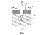
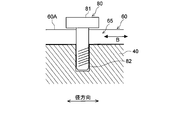
- 6A is a cross-sectional view (corresponding to a cross section taken along line EE in FIG. 4) showing a configuration example of the restraining member 80 and its peripheral structure.
- 6B is a cross-sectional view (corresponding to a cross section taken along line FF in FIG. 6A) showing a configuration example of the restraining member 80 and its peripheral structure.
- reference numerals shown in FIGS. 2 to 4 are used as appropriate.
- the post portion 82 is fixed to the fixing fin 40 so as to extend between the adjacent segments 60A to 60H (see FIG. 4).
- a male screw part is formed in a part attached to the fixed fin 40 in the column part 82
- a female screw part is formed in a part of the fixed fin 40 corresponding thereto, and these are screwed together to form the column part.
- 82 may be fixed to the fixing fin 40.
- the support 82 may be fixed to the fixed fin 40 by welding the support 82 to the fixed fin 40.
- the holding plate portion 81 is a plate-like member provided at the tip of the column portion 82, and extends in the circumferential direction from the column portion 82 so that the segments 60 ⁇ / b> A to 60 ⁇ / b> H are at least partially sandwiched between the fixing fin 40. It extends.
- a circumferential gap 65 may be formed at least when the rotary machine 1 is stopped.
- the circumferential gap 65 is formed by adjacent segments 60A to 60H being spaced apart from each other in the circumferential direction, and extends in the radial direction.
- the circumferential gap 65 has a constant gap width when the rotating machine 1 is stopped.
- the constraint between the adjacent segments 60A to 60H can be further weakened. Therefore, during operation the rotary machine 1, utilizing thermal expansion of each segment 60A ⁇ 60H of the movable fins 60 can be further reduced clearance H m.
- FIG. 7 is a plan view showing another configuration example of the segments 60A to 60H of the movable fin 60.
- the circumferential gap 65 may not have a constant width in the radial direction.
- the circumferential gap 65 has a wide portion 66 having a gap width larger than other portions in a part in the radial direction.
- the wide portion 66 is configured such that the column portion 82 of the restraining member 80 is inserted, and the circumferential gap 65 other than the wide portion 66 is configured to be smaller than the diameter of the column portion 82.
- the wide portion 66 has a certain length in the radial direction, and the segments 60A to 60H can slide in the radial direction with respect to the support portion 82 by the length in the radial direction of the wide portion 66. It has become.
- the circumferential gap 65 may have a narrow portion 67 having a narrower gap width on the distal end 62 side of the movable fin 60 than the circumferential gap 65 on the proximal end 61 side.
- the distal end 62 side of the movable fin 60 is narrower than the proximal end 61 side of the movable fin 60, so that the movable fin 60 is thermally expanded, and the distal end 62 side of each of the movable fin 60 is in the state of thermal expansion.
- the gap between the segments 60A to 60H becomes narrower, and fluid can be prevented from leaking from the gap between the segments 60A to 60H.
- each of the segments 60A to 60H of the movable fin 60 has a longer length on the base end portion 61 side than a length on the distal end portion 62 side.
- the base end portion 61 side has a larger amount of thermal expansion than the front end portion 62 side. Therefore, by making the circumferential gap 65 on the proximal end portion 61 side wider than the circumferential gap 65 on the distal end portion 62 side, thermal expansion on the proximal end portion 61 side of the movable fin 60 can be absorbed.
- the tip thickness of the movable fin 60 is smaller than the tip thickness of the fixed fin 40.
- the movable fins 60 have substantially the same thickness in the radial direction.
- the thickness of the fixed fin 40 gradually decreases from the base end portion 41 side toward the tip end portion 42 side.
- the thickness of the movable fin 60 is smaller than the thickness of the fixed fin 40.
- the distal end region of the movable fin 60 may be configured such that the thickness gradually decreases from the proximal end portion 61 side toward the distal end portion 62 side. Also in this case, the thickness of the movable fin 60 is smaller than the thickness of the fixed fin 40 in the tip region.
- the clearance H m can be excessively narrow due to the thermal expansion of the movable fin 60 during the activation of the rotary machine 1. For this reason, there is a possibility that the rotating member 3 of the rotating machine 1 and the tip end portion 62 of the movable fin 60 come into contact with each other. Therefore, even if the rotating member 3 of the rotating machine 1 and the tip 62 of the movable fin 60 are in contact with each other by reducing the thickness of the tip of the movable fin 60 relative to the fixed fin 40, Heat generation and vibration caused by contact can be suppressed.
- the tip thickness of the fixed fin 40 relatively larger than that of the movable fin 60, the tip portion 42 of the fixed fin 40 caused by the fluid pressure difference between the axial sides of the movable fin 60 and the fixed fin 40. And the unintended displacement of the movable fin 60 accompanying the deformation of the fixed fin 40 can be suppressed.
- FIGS. 8A and 8B when the rotary machine 1 is stopped, a gap 90 is formed between the distal end portion 62 of the movable fin 60 and the distal end portion 42 of the fixed fin 40.
- FIG. 8A is a cross-sectional view showing tip regions of the fixed fin and the movable fin when the rotary machine is stopped in the sealing device according to another embodiment.
- FIG. 8B is a cross-sectional view showing the tip regions of the fixed fin and the movable fin during the rated operation of the rotary machine in the sealing device according to another embodiment.
- the movable fin 60 has a substantially constant thickness from the base end portion 61 side to the tip end portion 62 side.
- the fixed fin 40 is at least partially curved so as to protrude to the upstream side (high pressure side) in the fluid flow direction between the base end portion 41 (see FIG. 2) and the tip end portion 42.
- the fixed fin 40 may have a tapered surface inclined in a direction away from the movable fin 60 on the tip end portion 42 side. In this way, when the rotating machine 1 is stopped, a gap 90 is formed between the tip end portion 62 of the movable fin 60 and the tip end portion 42 of the fixed fin 40.
- the tip end portion 62 of the movable fin 60 is pressed against the high-pressure side surface of the fixed fin 40 by the movable fin 60 positioned on the high-pressure side (that is, FIG. 8B).
- the tip end 62 side of the movable fin 60 is deformed.
- the clearance formed between the rotating member 3 and the movable fin 60 is H m1
- the clearance formed between the rotating member 3 and the fixed fin 40 is Let H f1 .
- the clearance formed between the rotating member 3 and the movable fin 60 is H m2
- the clearance formed between the rotating member 3 and the fixed fin 40 is H f2 .
- the fixed fin 40 and the movable fin 60 may be configured to satisfy H m1 ⁇ H f1 and H m2 ⁇ H f2 .
- the fixed fin 40 and the movable fin 60 are curved in the axial section of the rotary machine 1. According to this configuration, the length of the movable fin 60 (distance from the proximal end portion 61 to the distal end portion 62 of the movable fin 60) can be sufficiently ensured, and the movable fin 60 can be secured during operation of the rotary machine 1. You can enjoy an excellent effect of suppressing leakage flow by reducing the clearance H m using thermal elongation deformation.
- the fixed fin 40 and the movable fin 60 may further have the following configuration.
- An angle tangential T 1 is formed to the radial direction at the base end portion 41 side of the fixed fin 40 and theta f1, an angle tangential T 2 with respect to the radial direction at the distal end 42 of the fixed fin 40 theta Let f2 .
- the movable fin 60 is curved along the fixed fin 40 so that the tangential direction T in the axial section of the surface of the fixed fin 40 on the movable fin 60 side satisfies the relational expression ⁇ f1 > ⁇ f2. Yes.
- H m is becomes smaller than when it stops rotating machine 1 can suppress leakage flow of fluid through the clearance H m.
- the rotating machine 1 includes a stationary member 2, a rotating member 3 provided to face the stationary member 2, and an annular gap 5 between the stationary member 2 and the rotating member 3.
- the sealing device 4 see FIGS. 1 to 9 provided, the following effects can be obtained. Since the rotating machine 1 includes the sealing device 4 shown in FIGS. 1 to 9, the clearance H m between the tip 62 of the movable fin 60 of the sealing device 4 and the rotating member 3 (or the stationary member 2). the person at the time of driving the rotary machine 1 is smaller than when it stops rotating machine 1, it is possible to suppress the leakage flow of fluid through the clearance H m, thus can improve the efficiency of the rotary machine 1.
- the present invention is not limited to the above-described embodiments, and includes forms obtained by modifying the above-described embodiments and forms obtained by appropriately combining these forms.
- the steam turbine is illustrated as the rotating machine 1 to which the sealing device 4 is applied.
- the rotating machine 1 to which the sealing device 4 is applied is, for example, a gas turbine or the like.
- the present invention can also be applied to other rotating machines in which leakage flow between the stationary member 2 and the rotating member 3 is a problem.
- the casing 21 was illustrated among the stationary members 2 as a site
- part of the sealing apparatus 4 is not limited to this.
- it is attached to the hub shroud 24 a of the stationary blade 24 so as to face the outer peripheral surface of the rotor 31.
- the sealing device 4 is comprised so that the leakage flow of the fluid in the annular clearance 5 between the rotor 31 and the hub shroud 24a may be suppressed.
- the sealing device 4 may be attached to the rotating member 3 as shown in FIGS. 10C and 10D.
- the sealing device 4 is attached to the outer peripheral surface of the rotor 31 so as to face the hub shroud 24 a of the stationary blade 24.
- the sealing device 4 is comprised so that the leakage flow of the fluid in the annular clearance 5 between the rotor 31 and the hub shroud 24a may be suppressed.
- FIG. 10C the sealing device 4 is attached to the outer peripheral surface of the rotor 31 so as to face the hub shroud 24 a of the stationary blade 24.
- the sealing device 4 is comprised so that the leakage flow of the fluid in the annular clearance 5 between the rotor 31 and the hub shroud 24a may be suppressed.
- FIG. 10C the sealing device 4 is attached to the outer peripheral surface of the
- the sealing device 4 is attached to the tip shroud 32 a of the rotor blade 32 so as to face the inner wall surface of the casing 21. And the sealing device 4 is comprised so that the leakage flow of the fluid in the annular clearance 5 between the chip
- expressions representing shapes such as quadrangular shapes and cylindrical shapes represent not only geometrically strict shapes such as quadrangular shapes and cylindrical shapes, but also irregularities and chamfers as long as the same effects can be obtained.
- a shape including a part or the like is also expressed.
- the expression “comprising”, “including”, or “having” one constituent element is not an exclusive expression that excludes the presence of the other constituent elements.
- Rotating machine steam turbine
- Static member 3
- Rotating member 4 Sealing device 5
- Annular gap 21
- Casing 24
- Stator blade 25
- Groove 31
- Rotor (rotating shaft) 32
- Rotor blades 40, 40A to 40C
- Fixed fin 41
- Base end 42
- Front end 50
- Seal ring 60
- Movable fins 60A to 60H Segment
- Base end 62
- End Fixed region 64
- Bolt 65
- Circumferential gap 80
- Holding plate 82
- Supporting part 90 Clearance
Landscapes
- Engineering & Computer Science (AREA)
- General Engineering & Computer Science (AREA)
- Mechanical Engineering (AREA)
- Chemical & Material Sciences (AREA)
- Combustion & Propulsion (AREA)
- Turbine Rotor Nozzle Sealing (AREA)
- Sealing Using Fluids, Sealing Without Contact, And Removal Of Oil (AREA)
- Structures Of Non-Positive Displacement Pumps (AREA)
Abstract
Description
特許文献1に記載の自動調整シールは、水平の平坦面からなる合わせ面において互いに当接可能な固定シールリングと可動シールリングとを含んでいる。可動シールリングは、回転機械のロータの上方及び下方において、それぞれ、ロータの外周面に沿って120度の角度範囲に亘って設けられる。一方、固定シールリングは、ロータの左右両側において、ロータの外周面に亘って60度の角度範囲に設けられる。可動シールリングは、固定シールリングから遠ざかる方向に弾性体によって付勢されている。回転機械の定格運転時には、可動シールリングは、流体によって固定シールリングに向かって押圧され、シール間隙が減少するようになっている。
回転機械の静止部材と回転部材との間の環状隙間を介した流体の漏れ流れを抑制するためのシール装置であって、
前記環状隙間に設けられる環状の固定フィンと、
前記環状隙間内において前記固定フィンに対して軸方向に隣接して設けられる環状の可動フィンと、を備え、
前記可動フィンは、
前記固定フィンよりも熱膨張係数が大きく、
前記可動フィンの基端側の固定領域において前記固定フィンに固定されている。
前記可動フィンは、該可動フィンの基端側の前記固定領域のみにおいて前記固定フィンに固定されている。
このため、回転機械の運転時にシール装置が高温の流体に曝されると、可動フィンは基端側の固定領域を起点として先端側が熱伸びする。この際、固定フィンよりも可動フィンの熱膨張係数が大きいため、可動フィンの先端側の熱伸び量は固定フィンの先端側の熱伸び量よりも大きい。よって、シール装置の可動フィンの先端と回転機械の静止部材又は回転部材との間のクリアランスHmは、回転機械の停止時に比べて小さくなり、当該クリアランスHmを介した流体の漏れ流れを抑制できる。
前記可動フィンは、周方向に配列される複数のセグメントを含み、
各々の前記セグメントは、前記固定フィンに固定される前記固定領域を先端側に有する。
前記固定領域は、前記セグメントの基端側の周方向範囲における一部の範囲であり、
前記可動フィンの各々の前記セグメントは、前記固定領域を起点とした径方向および周方向の熱伸びが許容されている。
前記固定領域は、前記セグメントの基端側の前記周方向範囲のうち、周方向における中央に位置する。
前記固定領域よりも前記可動フィンの先端側において前記固定フィンに取り付けられ、前記可動フィンの各々の前記セグメントの前記固定フィンからの浮き上がりを抑制するための拘束部材をさらに備える。
この点、上記(6)の構成によれば、固定領域よりも可動フィンの先端側において固定フィンに取り付けられる拘束部材を設けたので、可動フィンの各セグメントの固定フィンからの浮き上がりを抑制できる。
前記拘束部材は、
隣接する前記セグメント間において延在するように前記固定フィンに固定された支柱部と、
前記支柱部の先端に設けられて、前記固定フィンとの間に前記セグメントが少なくとも部分的に挟まれるように、前記支柱部から周方向に延びる押さえ板部と、
を含む。
隣接する前記セグメント間には、少なくとも前記回転機械の停止時において、周方向間隙が形成される。
前記可動フィンの前記セグメントは偶数個である。
前記可動フィンの先端厚さは、前記固定フィンの先端厚さよりも小さい。
この点、上記(10)の構成によれば、可動フィンの先端厚さを固定フィンに比べて相対的に小さくしたので、回転機械の回転部材又は静止部材と可動フィンの先端部とが万が一接触した場合であっても、接触に起因した発熱や振動を抑制できる。一方、固定フィンの先端厚さを可動フィンに比べて相対的に大きくすることで、可動フィン及び固定フィンの軸方向両側における流体の圧力差に起因した固定フィン先端部の変形を抑制し、固定フィンの変形に伴う可動フィンの意図せぬ変位を抑制できる。
前記回転機械の停止時において、前記静止部材又は前記回転部材と前記可動フィンとの間に形成されるクリアランスをHm1とし、
前記回転機械の停止時において、前記静止部材又は前記回転部材と前記固定フィンとの間に形成されるクリアランスをHf1とし、
前記回転機械の定格運転時において、前記静止部材又は前記回転部材と前記可動フィンとの間に形成されるクリアランスをHm2とし、
前記回転機械の定格運転時において、前記静止部材又は前記回転部材と前記固定フィンとの間に形成されるクリアランスをHf2としたとき、
Hm1≧Hf1、且つ、Hm2<Hf2を満たす。
また、回転機械の定格運転時において、静止部材又は回転部材と可動フィンとの間に形成されるクリアランスHm2は、静止部材又は回転部材と固定フィンとの間に形成されるクリアランスHf2よりも小さいため、当該クリアランスHm2を介した流体の漏れ流れを抑制できる。
前記可動フィンは、前記固定フィンからみて高圧側に設けられる。
前記静止部材又は前記回転部材に形成された溝に嵌合するとともに、軸方向に並ぶ複数の前記固定フィンを先端側に有するシールリングをさらに備え、
前記可動フィンは、少なくとも、前記漏れ流れの最上流側に位置する前記固定フィンからみて高圧側に設けられる。
なお、仮に多段の固定フィンを有するシール装置において、下流側の固定フィンからみて高圧側に可動フィンを取り付けようとすると(すなわち隣接する固定フィン間に可動フィンを取り付けようとすると)、可動フィンのコンパクト化が求められる。そうすると、可動フィンの長さ(可動フィンの基端部から先端部までの距離)が十分でないため可動フィンの熱伸び量を十分に得ることは難しいことがある。この場合、回転機械の運転時において、可動フィンの熱伸び変形を利用したクリアランスHmの低減による漏れ流れ抑制効果が限定的になってしまう可能性がある。
前記回転機械の停止時において、前記可動フィンの先端部と前記固定フィンの先端部との間には隙間が形成されている。
前記固定フィン及び前記可動フィンは、先端側が基端側に対して高圧側に位置するように半径方向に対して斜めに延在している。
前記静止部材又は前記回転部材の一方に形成された溝に嵌合するとともに、少なくとも一つの前記固定フィンを先端側に有するシールリングをさらに備え、
前記可動フィンは、前記溝の軸方向範囲内に位置する該可動フィンの基端部から、前記溝の軸方向範囲外に位置する該可動フィンの先端部に向かって、半径方向に対して斜めに延在している。
前記可動フィンは、少なくとも前記可動フィンの前記基端部が前記溝内に存在するように配置される。
前記固定フィン及び前記可動フィンは、前記回転機械の軸方向断面内において湾曲している。
前記固定フィンの前記可動フィン側の表面の前記軸方向断面内における接線方向は、
前記固定フィンの基端側において前記接線方向が半径方向に対してなす角度をθf1とし、
前記固定フィンの先端側において前記接線方向が半径方向に対してなす角度をθf2としたとき、
θf1>θf2の関係式を満たし、
前記可動フィンは、前記固定フィンに沿って湾曲している。
回転機械の静止部材と回転部材との間の環状隙間を介した流体の漏れを抑制するためのシール装置であって、
前記環状隙間に設けられる環状の固定フィンと、
前記環状隙間内において前記固定フィンに対して軸方向に隣接して設けられる環状の可動フィンと、を備え、
前記回転機械の停止時において、前記静止部材又は前記回転部材と前記可動フィンとの間に形成されるクリアランスをHm1とし、
前記回転機械の停止時において、前記静止部材又は前記回転部材と前記固定フィンとの間に形成されるクリアランスをHf1とし、
前記回転機械の定格運転時において、前記静止部材又は前記回転部材と前記可動フィンとの間に形成されるクリアランスをHm2とし、
前記回転機械の定格運転時において、前記静止部材又は前記回転部材と前記固定フィンとの間に形成されるクリアランスをHf2としたとき、
Hm1≧Hf1、且つ、Hm2<Hf2を満たす。
また、回転機械の定格運転時において、静止部材又は回転部材と可動フィンとの間に形成されるクリアランスHm2は、静止部材又は回転部材と固定フィンフィンとの間に形成されるクリアランスHf2よりも小さいため、当該クリアランスHm2を介した流体の漏れ流れを抑制できる。
静止部材と、
前記静止部材に対して対向して設けられる回転部材と、
前記静止部材と前記回転部材との間の環状隙間に設けられる請求項1乃至19の何れか一項に記載のシール装置と、を備える。
ロータ31は、ケーシング21の内部を貫通するように配置され、軸線Oを中心として回転可能に軸受6,7に支持されている。このロータ31には、ケーシング21の内部において、外周部にロータディスク33を介して動翼32が固定されている。動翼32は、ロータ31の軸方向(軸線Oの方向)に所定間隔で複数段にわたって設けられている。各々の動翼32の外形側(チップ側)には、周方向に延在したチップシュラウド32aが設けられている。チップシュラウド32aは、ケーシング21の環状部21bに対向するように位置している。一方、ケーシング21側には、複数段の動翼32に対して軸方向に交互に配列されるように、複数段の静翼24が固定されている。各々の静翼24の内径側(ハブ側)には、周方向に延在したハブシュラウド24aが設けられている。ハブシュラウド24aは、ロータ31の外周面に対向するように位置している。
また、ケーシング21の内部には、動翼32及び静翼24が配設される通路に蒸気通路23が形成されており、この蒸気通路23が蒸気入口22及び蒸気出口26に連通している。
これらの図では、一例として、静止部材2(例えばケーシング21)にシール装置4が取り付けられた構成を示している。具体的には、シール装置4は、動翼32のチップシュラウド32aに対向するように、ケーシング21の環状部21bの内壁面に取り付けられている。なお、後述するように、シール装置4は、回転部材3(例えばロータ31)に取り付けられてもよい。
図5Aは、一実施形態に係るシール装置4において、回転機械1の停止時における固定フィン40及び可動フィン60の先端領域を示す断面図である。図5Bは、一実施形態に係るシール装置4において、回転機械1の定格運転時における固定フィン40及び可動フィン60の先端領域を示す断面図である。
図5Bに示すように、回転機械1の運転時、シール装置4が高温の流体に曝されると、可動フィン60は基端部61側の固定領域63を起点として、図中矢印B方向に先端部62側が熱伸びする。この際、固定フィン40よりも可動フィン60の熱膨張係数が大きいため、可動フィン60の先端部62側の熱伸び量は固定フィン40の先端部42側の熱伸び量よりも大きくなる。そのため、シール装置4の可動フィン60の先端部62と回転部材3との間のクリアランスHmは、図5Aに示す回転機械1の停止時に比べて小さくなり、当該クリアランスHmを介した流体の漏れ流れを抑制できる。
この構成により、回転機械1の運転時、可動フィン60は高圧の流体によって固定フィン40側に押し付けられるため、可動フィン60の固定フィン40からの浮き上がりを抑制できる。
この構成により、可動フィン60の長さ(可動フィン60の基端部61から先端部62までの距離)を十分に確保することができ、回転機械1の運転時において、可動フィン60の熱伸び変形を利用したクリアランスHmの低減による漏れ流れの優れた抑制効果を享受できる。
なお、図示は省略するが、固定フィン40及び可動フィン60は、ロータ31の軸線Oに直交するように、半径方向に沿って延在していてもよい。
シール装置4は、静止部材2の溝25に嵌合するとともに、少なくとも一つの固定フィン40を先端側に有するシールリング50をさらに備える。
可動フィン60は、溝25の軸方向範囲内に位置する該可動フィン60の基端部61から、溝25の軸方向範囲外に位置する該可動フィン60の先端部62に向かって、半径方向に対して斜めに延在している。
これにより、可動フィン60の長さ(可動フィン60の基端部61から先端部62までの距離)を十分に確保することができ、回転機械1の運転時において、可動フィン60の熱伸び変形を利用したクリアランスHmの低減による漏れ流れの優れた抑制効果を享受できる。
この構成によれば、可動フィン60の基端部61が溝25内に位置することから、可動フィン60の長さ(可動フィン60の基端部61から先端部62までの距離)をより一層大きくすることができる。
なお、仮に多段の固定フィン40A,40B,40Cを有するシール装置4において、下流側の固定フィン40Cからみて高圧側に可動フィン60を取り付けようとすると(すなわち隣接する固定フィン40B,40C間に可動フィン60を取り付けようとすると)、可動フィン60のコンパクト化が求められる。そうすると、可動フィン60の長さ(可動フィン60の基端部61から先端部62までの距離)が十分でないため可動フィン60の熱伸び量を十分に得ることは難しいことがある。この場合、回転機械1の運転時において、可動フィン60の熱伸び変形を利用したクリアランスHmの低減による漏れ流れ抑制効果が限定的になってしまう可能性がある。
図5Aに示すように、回転機械1の停止時において、回転部材3と可動フィン60との間に形成されるクリアランスをHm1とし、回転部材3と固定フィン40との間に形成されるクリアランスをHf1とする。また、図5Bに示すように、回転機械1の定格運転時において、回転部材3と可動フィン60との間に形成されるクリアランスをHm2とし、回転部材3と固定フィン40との間に形成されるクリアランスをHf2とする。
この場合、固定フィン40及び可動フィン60は、Hm1≧Hf1、且つ、Hm2<Hf2を満たすように構成される。
また、図5Bに示す回転機械1の定格運転時において、回転部材3と可動フィン60との間に形成されるクリアランスHm2は、回転部材3と固定フィン40との間に形成されるクリアランスHf2よりも小さいため、当該クリアランスHm2を介した流体の漏れ流れを抑制できる。
複数のセグメント60A~60Hは、偶数個であってもよい。これにより、半割構造の固定フィン40の採用によってシール装置4の組立作業を効率化できる。この場合、整数個のセグメント60A~60Hを組み付けた半環状の固定フィン40を一対準備し、これらを回転機械1に取り付けることでシール装置4の組み立てが完了する。
この場合、固定領域63は、セグメント60A~60Hの基端部61側の周方向範囲における一部の範囲であり、可動フィン60の各々のセグメント60A~60Hは、固定領域63を起点とした径方向(図2乃至図4の矢印B方向)および周方向(図3及び図4の矢印C方向)の熱伸びが許容されていてもよい。
さらにこの場合、固定領域63は、セグメント60A~60Hの基端部61側の周方向範囲のうち、周方向における中央に位置してもよい。
さらに、各セグメント60A~60Hの固定領域63を各セグメント60A~60Hの周方向における中央に設けることによって、各セグメント60A~60Hの固定領域63の周方向両側における領域は固定フィン40に拘束されない。よって、回転機械1の運転時において可動フィン60の各セグメント60A~60Hがより一層自由に熱伸び変形することができ、クリアランスHmをより一層低減できる。これにより、クリアランスHmを介した流体の漏れ流れをより効果的に抑制できる。
上述したように、可動フィン60の各セグメント60A~60Hの先端部62側は固定フィン40に固定されていない。このため、可動フィン60の先端部62側と固定フィン40の先端部42側との間に流体が浸入し、可動フィン60の各セグメント60A~60Hを固定フィン40から浮き上がらせてしまう場合がある。
そこで、固定領域63よりも可動フィン60の先端部62側において固定フィン40に取り付けられる拘束部材80を設けることにより、可動フィン60の各セグメント60A~60Hの固定フィン40からの浮き上がりを抑制できる。
支柱部82は、隣接するセグメント60A~60H(図4参照)間において延在するように固定フィン40に固定される。例えば、支柱部82のうち固定フィン40に取り付けられる部位に雄ねじ部を形成しておき、これに対応する固定フィン40の部位に雌ねじ部を形成しておき、これらを螺合することによって支柱部82を固定フィン40に固定してもよい。あるいは、固定フィン40に対して支柱部82を溶接することによって、支柱部82を固定フィン40に固定してもよい。
押さえ板部81は、支柱部82の先端に設けられた板状部材であって、固定フィン40との間にセグメント60A~60Hが少なくとも部分的に挟まれるように、支柱部82から周方向に延びている。
このように、隣接するセグメント60A~60H間に周方向間隙65が形成されていることにより、隣接するセグメント60A~60H間の拘束をより一層弱めることができる。よって、回転機械1の運転時において可動フィン60の各セグメント60A~60Hの熱伸びを利用してクリアランスHmをより一層低減できる。
他の構成例において、周方向間隙65は、径方向において一定の幅を有しなくてもよい。すなわち、同図に示す例では、周方向間隙65は、径方向の一部において間隙幅が他の部位より大きい幅広部66を有している。幅広部66は、拘束部材80の支柱部82が挿通される構成となっており、幅広部66以外の周方向間隙65は、支柱部82の径よりも小さく構成されている。また、幅広部66は径方向に一定の長さを有しており、この幅広部66の径方向の長さだけ、各セグメント60A~60Hは支柱部82に対して径方向にスライド移動可能となっている。
また、周方向間隙65は、可動フィン60の先端部62側において、基端部61側の周方向間隙65よりも間隙幅が狭い幅狭部67を有していてもよい。このように、可動フィン60の先端部62側の方が、可動フィン60の基端部61側よりも間隙幅を狭くすることによって、可動フィン60が熱膨張した状態において先端部62側の各セグメント60A~60H間の隙間がより狭まり、各セグメント60A~60H間の隙間から流体が漏れ出ることを阻止できる。また、可動フィン60の各々のセグメント60A~60Hは、基端部61側の長さの方が先端部62側の長さよりも長い。そのため、回転機械1の運転時、基端部61側の方が先端部62側よりも熱膨張量が大きくなる。そこで、基端部61側の周方向間隙65を先端部62側の周方向間隙65よりも広くすることによって、可動フィン60の基端部61側の熱膨張を吸収できる。
例えば、図示されるように、可動フィン60は、径方向において略同一の厚さを有している。一方、固定フィン40は、基端部41側から先端部42側に向けて徐々に厚さが薄くなっている。そして、先端領域において、可動フィン60の厚さは固定フィン40の厚さよりも小さい。
あるいは、図示しないが、可動フィン60の先端領域において、基端部61側から先端部62側へ向けて徐々に厚さが小さくなるように構成されていてもよい。この場合も、先端領域において、可動フィン60の厚さは固定フィン40の厚さよりも小さい。
そのため、可動フィン60の先端厚さを固定フィン40に比べて相対的に小さくすることによって、回転機械1の回転部材3と可動フィン60の先端部62とが万が一接触した場合であっても、接触に起因した発熱や振動を抑制できる。一方、固定フィン40の先端厚さを可動フィン60に比べて相対的に大きくすることで、可動フィン60及び固定フィン40の軸方向両側における流体の圧力差に起因した固定フィン40の先端部42の変形を抑制し、固定フィン40の変形に伴う可動フィン60の意図せぬ変位を抑制できる。
この場合、固定フィン40及び可動フィン60は、Hm1≧Hf1、且つ、Hm2<Hf2を満たすように構成されてもよい。
この構成によれば、可動フィン60の長さ(可動フィン60の基端部61から先端部62までの距離)を十分に確保することができ、回転機械1の運転時において、可動フィン60の熱伸び変形を利用したクリアランスHmの低減による漏れ流れの優れた抑制効果を享受できる。
固定フィン40の基端部41側において接線方向T1が半径方向に対してなす角度をθf1とし、固定フィン40の先端部42側において接線方向T2が半径方向に対してなす角度をθf2とする。このとき、固定フィン40の可動フィン60側の表面の軸方向断面内における接線方向Tが、θf1>θf2の関係式を満たすように、可動フィン60は固定フィン40に沿って湾曲している。
この回転機械1は、図1乃至図9に示すシール装置4を備えているので、シール装置4の可動フィン60の先端部62と回転部材3(又は静止部材2)との間のクリアランスHmは、回転機械1の運転時の方が回転機械1の停止時に比べて小さくなり、当該クリアランスHmを介した流体の漏れ流れを抑制でき、よって回転機械1の効率を向上できる。
例えば、上述した実施形態では、図1に示すように、上記シール装置4が適用される回転機械1として蒸気タービンを例示したが、シール装置4が適用される回転機械1は、例えばガスタービン等のように、静止部材2と回転部材3との間における漏れ流れが課題となる他の回転機械にも適用可能である。
他の実施形態では、図10Bに示すように、ロータ31の外周面に対向するように、静翼24のハブシュラウド24aに取り付けられる。そして、シール装置4は、ロータ31とハブシュラウド24aとの間の環状隙間5における流体の漏れ流れを抑制するように構成される。
さらに他の実施形態では、図10C及び図10Dに示すように、シール装置4は回転部材3に取り付けられてもよい。図10Cに示す例では、シール装置4は、静翼24のハブシュラウド24aに対向するように、ロータ31の外周面に取り付けられる。そして、シール装置4は、ロータ31とハブシュラウド24aとの間の環状隙間5における流体の漏れ流れを抑制するように構成される。図10Dに示す例では、シール装置4は、ケーシング21の内壁面に対向するように、動翼32のチップシュラウド32aに取り付けられる。そして、シール装置4は、チップシュラウド32aとケーシング21との間の環状隙間5における流体の漏れ流れを抑制するように構成される。
例えば、「同一」、「等しい」及び「均質」等の物事が等しい状態であることを表す表現は、厳密に等しい状態を表すのみならず、公差、若しくは、同じ機能が得られる程度の差が存在している状態も表すものとする。
例えば、四角形状や円筒形状等の形状を表す表現は、幾何学的に厳密な意味での四角形状や円筒形状等の形状を表すのみならず、同じ効果が得られる範囲で、凹凸部や面取り部等を含む形状も表すものとする。
一方、一の構成要素を「備える」、「含む」、又は、「有する」という表現は、他の構成要素の存在を除外する排他的な表現ではない。
2 静止部材
3 回転部材
4 シール装置
5 環状隙間
21 ケーシング
24 静翼
25 溝
31 ロータ(回転軸)
32 動翼
40,40A~40C 固定フィン
41 基端部
42 先端部
50 シールリング
60 可動フィン
60A~60H セグメント
61 基端部
62 先端部
63 固定領域
64 ボルト
65 周方向間隙
80 拘束部材
81 押さえ板部
82 支柱部
90 隙間
Claims (21)
- 回転機械の静止部材と回転部材との間の環状隙間を介した流体の漏れ流れを抑制するためのシール装置であって、
前記環状隙間に設けられる環状の固定フィンと、
前記環状隙間内において前記固定フィンに対して軸方向に隣接して設けられる環状の可動フィンと、を備え、
前記可動フィンは、
前記固定フィンよりも熱膨張係数が大きく、
前記可動フィンの基端側の固定領域において前記固定フィンに固定されている
ことを特徴とするシール装置。 - 前記可動フィンは、該可動フィンの基端側の前記固定領域のみにおいて前記固定フィンに固定されていることを特徴とする請求項1に記載のシール装置。
- 前記可動フィンは、周方向に配列される複数のセグメントを含み、
各々の前記セグメントは、前記固定フィンに固定される前記固定領域を先端側に有することを特徴とする請求項1又は2に記載のシール装置。 - 前記固定領域は、前記セグメントの基端側の周方向範囲における一部の範囲であり、
前記可動フィンの各々の前記セグメントは、前記固定領域を起点とした径方向および周方向の熱伸びが許容されていることを特徴とする請求項3に記載のシール装置。 - 前記固定領域は、前記セグメントの基端側の前記周方向範囲のうち、周方向における中央に位置すること特徴とする請求項4に記載のシール装置。
- 前記固定領域よりも前記可動フィンの先端側において前記固定フィンに取り付けられ、前記可動フィンの各々の前記セグメントの前記固定フィンからの浮き上がりを抑制するための拘束部材をさらに備えることを特徴とする請求項3乃至5の何れか一項に記載のシール装置。
- 前記拘束部材は、
隣接する前記セグメント間において延在するように前記固定フィンに固定された支柱部と、
前記支柱部の先端に設けられて、前記固定フィンとの間に前記セグメントが少なくとも部分的に挟まれるように、前記支柱部から周方向に延びる押さえ板部と、
を含むことを特徴とする請求項6に記載のシール装置。 - 隣接する前記セグメント間には、少なくとも前記回転機械の停止時において、周方向間隙が形成されることを特徴とする請求項3乃至7の何れか一項に記載のシール装置。
- 前記可動フィンの前記セグメントは偶数個であることを特徴とする請求項3乃至8の何れか一項に記載のシール装置。
- 前記可動フィンの先端厚さは、前記固定フィンの先端厚さよりも小さいことを特徴とする請求項1乃至9の何れか一項に記載のシール装置。
- 前記回転機械の停止時において、前記静止部材又は前記回転部材と前記可動フィンとの間に形成されるクリアランスをHm1とし、
前記回転機械の停止時において、前記静止部材又は前記回転部材と前記固定フィンとの間に形成されるクリアランスをHf1とし、
前記回転機械の定格運転時において、前記静止部材又は前記回転部材と前記可動フィンとの間に形成されるクリアランスをHm2とし、
前記回転機械の定格運転時において、前記静止部材又は前記回転部材と前記固定フィンとの間に形成されるクリアランスをHf2としたとき、
Hm1≧Hf1、且つ、Hm2<Hf2を満たすことを特徴とする請求項1乃至10の何れか一項に記載のシール装置。 - 前記可動フィンは、前記固定フィンからみて高圧側に設けられることを特徴とする請求項1乃至11の何れか一項に記載のシール装置。
- 前記静止部材又は前記回転部材に形成された溝に嵌合するとともに、軸方向に並ぶ複数の前記固定フィンを先端側に有するシールリングをさらに備え、
前記可動フィンは、少なくとも、前記漏れ流れの最上流側に位置する前記固定フィンからみて高圧側に設けられることを特徴とする請求項12に記載のシール装置。 - 前記回転機械の停止時において、前記可動フィンの先端部と前記固定フィンの先端部との間には隙間が形成されていることを特徴とする請求項12又は13に記載のシール装置。
- 前記固定フィン及び前記可動フィンは、先端側が基端側に対して高圧側に位置するように半径方向に対して斜めに延在していることを特徴とする請求項1乃至14の何れか一項に記載のシール装置。
- 前記静止部材又は前記回転部材の一方に形成された溝に嵌合するとともに、少なくとも一つの前記固定フィンを先端側に有するシールリングをさらに備え、
前記可動フィンは、前記溝の軸方向範囲内に位置する該可動フィンの基端部から、前記溝の軸方向範囲外に位置する該可動フィンの先端部に向かって、半径方向に対して斜めに延在していることを特徴とする請求項1乃至15の何れか一項に記載のシール装置。 - 前記可動フィンは、少なくとも前記可動フィンの前記基端部が前記溝内に存在するように配置されたことを特徴とする請求項16に記載のシール装置。
- 前記固定フィン及び前記可動フィンは、前記回転機械の軸方向断面内において湾曲していることを特徴とする請求項1乃至17の何れか一項に記載のシール装置。
- 前記固定フィンの前記可動フィン側の表面の前記軸方向断面内における接線方向は、
前記固定フィンの基端側において前記接線方向が半径方向に対してなす角度をθf1とし、
前記固定フィンの先端側において前記接線方向が半径方向に対してなす角度をθf2としたとき、
θf1>θf2の関係式を満たし、
前記可動フィンは、前記固定フィンに沿って湾曲していることを特徴とする請求項18に記載のシール装置。 - 回転機械の静止部材と回転部材との間の環状隙間を介した流体の漏れを抑制するためのシール装置であって、
前記環状隙間に設けられる環状の固定フィンと、
前記環状隙間内において前記固定フィンに対して軸方向に隣接して設けられる環状の可動フィンと、を備え、
前記回転機械の停止時において、前記静止部材又は前記回転部材と前記可動フィンとの間に形成されるクリアランスをHm1とし、
前記回転機械の停止時において、前記静止部材又は前記回転部材と前記固定フィンとの間に形成されるクリアランスをHf1とし、
前記回転機械の定格運転時において、前記静止部材又は前記回転部材と前記可動フィンとの間に形成されるクリアランスをHm2とし、
前記回転機械の定格運転時において、前記静止部材又は前記回転部材と前記固定フィンとの間に形成されるクリアランスをHf2としたとき、
Hm1≧Hf1、且つ、Hm2<Hf2を満たすことを特徴とするシール装置。 - 静止部材と、
前記静止部材に対して対向して設けられる回転部材と、
前記静止部材と前記回転部材との間の環状隙間に設けられる請求項1乃至20の何れか一項に記載のシール装置と、を備えることを特徴とする回転機械。
Priority Applications (4)
| Application Number | Priority Date | Filing Date | Title |
|---|---|---|---|
| DE112016002476.2T DE112016002476T5 (de) | 2015-06-03 | 2016-05-23 | Dichtvorrichtung und drehmaschine |
| KR1020177034128A KR101973313B1 (ko) | 2015-06-03 | 2016-05-23 | 시일 장치 및 회전 기계 |
| US15/577,649 US10954808B2 (en) | 2015-06-03 | 2016-05-23 | Sealing device and rotary machine |
| CN201680030433.9A CN107614948B (zh) | 2015-06-03 | 2016-05-23 | 密封装置以及旋转机械 |
Applications Claiming Priority (2)
| Application Number | Priority Date | Filing Date | Title |
|---|---|---|---|
| JP2015112961A JP6490498B2 (ja) | 2015-06-03 | 2015-06-03 | シール装置および回転機械 |
| JP2015-112961 | 2015-06-03 |
Publications (1)
| Publication Number | Publication Date |
|---|---|
| WO2016194677A1 true WO2016194677A1 (ja) | 2016-12-08 |
Family
ID=57441066
Family Applications (1)
| Application Number | Title | Priority Date | Filing Date |
|---|---|---|---|
| PCT/JP2016/065169 Ceased WO2016194677A1 (ja) | 2015-06-03 | 2016-05-23 | シール装置および回転機械 |
Country Status (6)
| Country | Link |
|---|---|
| US (1) | US10954808B2 (ja) |
| JP (1) | JP6490498B2 (ja) |
| KR (1) | KR101973313B1 (ja) |
| CN (1) | CN107614948B (ja) |
| DE (1) | DE112016002476T5 (ja) |
| WO (1) | WO2016194677A1 (ja) |
Families Citing this family (6)
| Publication number | Priority date | Publication date | Assignee | Title |
|---|---|---|---|---|
| JP6785041B2 (ja) * | 2015-12-10 | 2020-11-18 | 三菱パワー株式会社 | シール構造及びタービン |
| DE202017103401U1 (de) * | 2017-06-06 | 2018-09-07 | Borgwarner Inc. | Verdichter für eine Aufladevorrichtung |
| JP7281991B2 (ja) * | 2019-07-23 | 2023-05-26 | 三菱重工業株式会社 | シール部材及び回転機械 |
| US11555410B2 (en) * | 2020-02-17 | 2023-01-17 | Pratt & Whitney Canada Corp. | Labyrinth seal with variable seal clearance |
| JP6808872B1 (ja) * | 2020-04-28 | 2021-01-06 | 三菱パワー株式会社 | シール装置及び回転機械 |
| CN117280144A (zh) * | 2022-02-18 | 2023-12-22 | 三菱重工业株式会社 | 密封装置及旋转机械以及密封装置的安装方法 |
Citations (3)
| Publication number | Priority date | Publication date | Assignee | Title |
|---|---|---|---|---|
| JPS6021502U (ja) * | 1983-07-22 | 1985-02-14 | 株式会社日立製作所 | 動翼先端部のシ−ル装置 |
| JPH0175664U (ja) * | 1987-11-09 | 1989-05-23 | ||
| JP2009085256A (ja) * | 2007-09-28 | 2009-04-23 | Hitachi Ltd | 回転流体機械のシール装置 |
Family Cites Families (22)
| Publication number | Priority date | Publication date | Assignee | Title |
|---|---|---|---|---|
| US1857961A (en) * | 1927-12-15 | 1932-05-10 | Westinghouse Electric & Mfg Co | Bi-metal packing |
| JPS6021502A (ja) | 1983-07-15 | 1985-02-02 | 東芝プラント建設株式会社 | 高圧用水抵抗器 |
| JPS6475664A (en) | 1987-09-18 | 1989-03-22 | Agency Ind Science Techn | Formation of x-ray transmitting film |
| CN2191280Y (zh) | 1994-05-20 | 1995-03-08 | 哈尔滨汽轮机厂 | 汽轮机、燃气轮机的刷子式汽封 |
| JPH11257014A (ja) | 1998-03-06 | 1999-09-21 | Toshiba Corp | 軸流タービンの作動流体漏洩防止装置 |
| US6065754A (en) * | 1998-04-15 | 2000-05-23 | General Electric Co. | Uniform clearance, temperature responsive, variable packing ring |
| JP3358993B2 (ja) | 1998-09-21 | 2002-12-24 | 三菱重工業株式会社 | ターボ回転機械の自動調整シール |
| US20100007093A1 (en) * | 2001-02-23 | 2010-01-14 | Grondahl Clayton M | Seal Assembly and Rotary Machine Containing Such Seal |
| US7578509B2 (en) * | 2001-02-23 | 2009-08-25 | Cmg Tech, Llc | Seal assembly and rotary machine containing such seal |
| GB2409245B (en) | 2003-12-19 | 2006-06-28 | Rolls Royce Plc | A seal arrangement in a machine |
| GB2413602B (en) * | 2004-04-26 | 2008-02-13 | Alstom Technology Ltd | Process for producing leaves for a leaf seal |
| JP2006266454A (ja) * | 2005-03-25 | 2006-10-05 | Matsumura Koki Kk | リング及びシール構造 |
| FR2914707B1 (fr) | 2007-04-05 | 2009-10-30 | Snecma Propulsion Solide Sa | Procede d'assemblage avec recouvrement de deux pieces ayant des coefficients de dilatation differents et assemblage ainsi obtenu |
| JP5347295B2 (ja) | 2008-03-26 | 2013-11-20 | Jfeスチール株式会社 | 亜鉛系めっき鋼板およびその製造方法 |
| JP2010217218A (ja) | 2009-03-13 | 2010-09-30 | Panasonic Corp | 定着ベルト及びそれを備えた定着装置 |
| US8596973B2 (en) * | 2009-12-07 | 2013-12-03 | Cmg Tech, Llc | Leaf seal assembly including polymer member and rotary machine containing such seal assembly |
| US8434999B2 (en) * | 2010-03-25 | 2013-05-07 | General Electric Company | Bimetallic spline seal |
| US8777563B2 (en) | 2011-01-31 | 2014-07-15 | General Electric Company | Axial brush seal |
| US8858166B2 (en) * | 2011-09-07 | 2014-10-14 | General Electric Company | Rotary machine seal assembly with butt gap seal elements |
| US9145788B2 (en) | 2012-01-24 | 2015-09-29 | General Electric Company | Retrofittable interstage angled seal |
| JP2014042142A (ja) | 2012-08-22 | 2014-03-06 | Yamaha Corp | アンテナユニット |
| CN203835467U (zh) | 2014-05-21 | 2014-09-17 | 南京博沃科技发展有限公司 | 可收放叶片式汽封 |
-
2015
- 2015-06-03 JP JP2015112961A patent/JP6490498B2/ja active Active
-
2016
- 2016-05-23 DE DE112016002476.2T patent/DE112016002476T5/de not_active Ceased
- 2016-05-23 CN CN201680030433.9A patent/CN107614948B/zh active Active
- 2016-05-23 WO PCT/JP2016/065169 patent/WO2016194677A1/ja not_active Ceased
- 2016-05-23 KR KR1020177034128A patent/KR101973313B1/ko active Active
- 2016-05-23 US US15/577,649 patent/US10954808B2/en active Active
Patent Citations (3)
| Publication number | Priority date | Publication date | Assignee | Title |
|---|---|---|---|---|
| JPS6021502U (ja) * | 1983-07-22 | 1985-02-14 | 株式会社日立製作所 | 動翼先端部のシ−ル装置 |
| JPH0175664U (ja) * | 1987-11-09 | 1989-05-23 | ||
| JP2009085256A (ja) * | 2007-09-28 | 2009-04-23 | Hitachi Ltd | 回転流体機械のシール装置 |
Also Published As
| Publication number | Publication date |
|---|---|
| JP2016223603A (ja) | 2016-12-28 |
| CN107614948B (zh) | 2020-04-07 |
| KR20170140347A (ko) | 2017-12-20 |
| US20180163557A1 (en) | 2018-06-14 |
| CN107614948A (zh) | 2018-01-19 |
| KR101973313B1 (ko) | 2019-04-26 |
| JP6490498B2 (ja) | 2019-03-27 |
| US10954808B2 (en) | 2021-03-23 |
| DE112016002476T5 (de) | 2018-02-15 |
Similar Documents
| Publication | Publication Date | Title |
|---|---|---|
| JP6490498B2 (ja) | シール装置および回転機械 | |
| JP5670789B2 (ja) | シュラウド付きガスタービンブレードの能動的チップクリアランス制御及び関連方法 | |
| JP6632206B2 (ja) | 局所弾性流体力学パッドを有する面シール | |
| JP5567077B2 (ja) | 回転機械 | |
| KR101516102B1 (ko) | 축 시일 장치 및 이것을 구비하는 회전 기계 | |
| WO2015115558A1 (ja) | シール構造、及び回転機械 | |
| JP2009144546A (ja) | ターボチャージャ | |
| JP2015187442A (ja) | 分割リング流体力学的面シールの個別に応従性のある分割片 | |
| KR20130114165A (ko) | 터빈 | |
| WO2014010052A1 (ja) | 軸流流体機械 | |
| JP2002013647A (ja) | 軸シール機構及びガスタービン | |
| US20110163505A1 (en) | Adverse Pressure Gradient Seal Mechanism | |
| JP2014141912A (ja) | 回転機械 | |
| CN101297118A (zh) | 用于离心压缩机的静止密封环 | |
| JP2010106778A (ja) | 蒸気タービンのシール構造および蒸気タービン | |
| JP2015096729A (ja) | タービン | |
| JP6012519B2 (ja) | タービン、及びこれを備えた回転機械 | |
| JP6712873B2 (ja) | シール構造及びターボ機械 | |
| JP5917311B2 (ja) | 軸流タービン | |
| JP2009085256A (ja) | 回転流体機械のシール装置 | |
| JP2014125986A (ja) | シール装置、およびそれを用いた回転機械 | |
| WO2014115706A1 (ja) | シール機構及びシール機構を備える回転機械 | |
| JP2011247307A (ja) | ラビリンスシール装置 | |
| US11092068B2 (en) | Variable geometry turbocharger | |
| WO2019077962A1 (ja) | 過給機のシール構造 |
Legal Events
| Date | Code | Title | Description |
|---|---|---|---|
| 121 | Ep: the epo has been informed by wipo that ep was designated in this application |
Ref document number: 16803112 Country of ref document: EP Kind code of ref document: A1 |
|
| ENP | Entry into the national phase |
Ref document number: 20177034128 Country of ref document: KR Kind code of ref document: A |
|
| WWE | Wipo information: entry into national phase |
Ref document number: 15577649 Country of ref document: US |
|
| WWE | Wipo information: entry into national phase |
Ref document number: 112016002476 Country of ref document: DE |
|
| 122 | Ep: pct application non-entry in european phase |
Ref document number: 16803112 Country of ref document: EP Kind code of ref document: A1 |