WO2016194489A1 - 衝突緩和装置 - Google Patents
衝突緩和装置 Download PDFInfo
- Publication number
- WO2016194489A1 WO2016194489A1 PCT/JP2016/062086 JP2016062086W WO2016194489A1 WO 2016194489 A1 WO2016194489 A1 WO 2016194489A1 JP 2016062086 W JP2016062086 W JP 2016062086W WO 2016194489 A1 WO2016194489 A1 WO 2016194489A1
- Authority
- WO
- WIPO (PCT)
- Prior art keywords
- operation determination
- vehicle
- unit
- preceding vehicle
- host vehicle
- Prior art date
- Legal status (The legal status is an assumption and is not a legal conclusion. Google has not performed a legal analysis and makes no representation as to the accuracy of the status listed.)
- Ceased
Links
Images



Classifications
-
- B—PERFORMING OPERATIONS; TRANSPORTING
- B60—VEHICLES IN GENERAL
- B60W—CONJOINT CONTROL OF VEHICLE SUB-UNITS OF DIFFERENT TYPE OR DIFFERENT FUNCTION; CONTROL SYSTEMS SPECIALLY ADAPTED FOR HYBRID VEHICLES; ROAD VEHICLE DRIVE CONTROL SYSTEMS FOR PURPOSES NOT RELATED TO THE CONTROL OF A PARTICULAR SUB-UNIT
- B60W30/00—Purposes of road vehicle drive control systems not related to the control of a particular sub-unit, e.g. of systems using conjoint control of vehicle sub-units
- B60W30/08—Active safety systems predicting or avoiding probable or impending collision or attempting to minimise its consequences
- B60W30/09—Taking automatic action to avoid collision, e.g. braking and steering
-
- B—PERFORMING OPERATIONS; TRANSPORTING
- B60—VEHICLES IN GENERAL
- B60K—ARRANGEMENT OR MOUNTING OF PROPULSION UNITS OR OF TRANSMISSIONS IN VEHICLES; ARRANGEMENT OR MOUNTING OF PLURAL DIVERSE PRIME-MOVERS IN VEHICLES; AUXILIARY DRIVES FOR VEHICLES; INSTRUMENTATION OR DASHBOARDS FOR VEHICLES; ARRANGEMENTS IN CONNECTION WITH COOLING, AIR INTAKE, GAS EXHAUST OR FUEL SUPPLY OF PROPULSION UNITS IN VEHICLES
- B60K31/00—Vehicle fittings, acting on a single sub-unit only, for automatically controlling vehicle speed, i.e. preventing speed from exceeding an arbitrarily established velocity or maintaining speed at a particular velocity, as selected by the vehicle operator
- B60K31/0066—Vehicle fittings, acting on a single sub-unit only, for automatically controlling vehicle speed, i.e. preventing speed from exceeding an arbitrarily established velocity or maintaining speed at a particular velocity, as selected by the vehicle operator responsive to vehicle path curvature
-
- B—PERFORMING OPERATIONS; TRANSPORTING
- B60—VEHICLES IN GENERAL
- B60T—VEHICLE BRAKE CONTROL SYSTEMS OR PARTS THEREOF; BRAKE CONTROL SYSTEMS OR PARTS THEREOF, IN GENERAL; ARRANGEMENT OF BRAKING ELEMENTS ON VEHICLES IN GENERAL; PORTABLE DEVICES FOR PREVENTING UNWANTED MOVEMENT OF VEHICLES; VEHICLE MODIFICATIONS TO FACILITATE COOLING OF BRAKES
- B60T7/00—Brake-action initiating means
- B60T7/12—Brake-action initiating means for automatic initiation; for initiation not subject to will of driver or passenger
- B60T7/22—Brake-action initiating means for automatic initiation; for initiation not subject to will of driver or passenger initiated by contact of vehicle, e.g. bumper, with an external object, e.g. another vehicle, or by means of contactless obstacle detectors mounted on the vehicle
-
- B—PERFORMING OPERATIONS; TRANSPORTING
- B60—VEHICLES IN GENERAL
- B60T—VEHICLE BRAKE CONTROL SYSTEMS OR PARTS THEREOF; BRAKE CONTROL SYSTEMS OR PARTS THEREOF, IN GENERAL; ARRANGEMENT OF BRAKING ELEMENTS ON VEHICLES IN GENERAL; PORTABLE DEVICES FOR PREVENTING UNWANTED MOVEMENT OF VEHICLES; VEHICLE MODIFICATIONS TO FACILITATE COOLING OF BRAKES
- B60T8/00—Arrangements for adjusting wheel-braking force to meet varying vehicular or ground-surface conditions, e.g. limiting or varying distribution of braking force
- B60T8/17—Using electrical or electronic regulation means to control braking
-
- B—PERFORMING OPERATIONS; TRANSPORTING
- B60—VEHICLES IN GENERAL
- B60T—VEHICLE BRAKE CONTROL SYSTEMS OR PARTS THEREOF; BRAKE CONTROL SYSTEMS OR PARTS THEREOF, IN GENERAL; ARRANGEMENT OF BRAKING ELEMENTS ON VEHICLES IN GENERAL; PORTABLE DEVICES FOR PREVENTING UNWANTED MOVEMENT OF VEHICLES; VEHICLE MODIFICATIONS TO FACILITATE COOLING OF BRAKES
- B60T8/00—Arrangements for adjusting wheel-braking force to meet varying vehicular or ground-surface conditions, e.g. limiting or varying distribution of braking force
- B60T8/32—Arrangements for adjusting wheel-braking force to meet varying vehicular or ground-surface conditions, e.g. limiting or varying distribution of braking force responsive to a speed condition, e.g. acceleration or deceleration
- B60T8/88—Arrangements for adjusting wheel-braking force to meet varying vehicular or ground-surface conditions, e.g. limiting or varying distribution of braking force responsive to a speed condition, e.g. acceleration or deceleration with failure responsive means, i.e. means for detecting and indicating faulty operation of the speed responsive control means
- B60T8/885—Arrangements for adjusting wheel-braking force to meet varying vehicular or ground-surface conditions, e.g. limiting or varying distribution of braking force responsive to a speed condition, e.g. acceleration or deceleration with failure responsive means, i.e. means for detecting and indicating faulty operation of the speed responsive control means using electrical circuitry
-
- G—PHYSICS
- G07—CHECKING-DEVICES
- G07C—TIME OR ATTENDANCE REGISTERS; REGISTERING OR INDICATING THE WORKING OF MACHINES; GENERATING RANDOM NUMBERS; VOTING OR LOTTERY APPARATUS; ARRANGEMENTS, SYSTEMS OR APPARATUS FOR CHECKING NOT PROVIDED FOR ELSEWHERE
- G07C5/00—Registering or indicating the working of vehicles
- G07C5/08—Registering or indicating performance data other than driving, working, idle, or waiting time, with or without registering driving, working, idle or waiting time
- G07C5/0808—Diagnosing performance data
-
- G—PHYSICS
- G08—SIGNALLING
- G08G—TRAFFIC CONTROL SYSTEMS
- G08G1/00—Traffic control systems for road vehicles
- G08G1/16—Anti-collision systems
-
- G—PHYSICS
- G08—SIGNALLING
- G08G—TRAFFIC CONTROL SYSTEMS
- G08G1/00—Traffic control systems for road vehicles
- G08G1/16—Anti-collision systems
- G08G1/161—Decentralised systems, e.g. inter-vehicle communication
- G08G1/162—Decentralised systems, e.g. inter-vehicle communication event-triggered
-
- G—PHYSICS
- G08—SIGNALLING
- G08G—TRAFFIC CONTROL SYSTEMS
- G08G1/00—Traffic control systems for road vehicles
- G08G1/16—Anti-collision systems
- G08G1/166—Anti-collision systems for active traffic, e.g. moving vehicles, pedestrians, bikes
-
- B—PERFORMING OPERATIONS; TRANSPORTING
- B60—VEHICLES IN GENERAL
- B60R—VEHICLES, VEHICLE FITTINGS, OR VEHICLE PARTS, NOT OTHERWISE PROVIDED FOR
- B60R21/00—Arrangements or fittings on vehicles for protecting or preventing injuries to occupants or pedestrians in case of accidents or other traffic risks
- B60R21/01—Electrical circuits for triggering passive safety arrangements, e.g. airbags, safety belt tighteners, in case of vehicle accidents or impending vehicle accidents
- B60R21/013—Electrical circuits for triggering passive safety arrangements, e.g. airbags, safety belt tighteners, in case of vehicle accidents or impending vehicle accidents including means for detecting collisions, impending collisions or roll-over
- B60R21/0134—Electrical circuits for triggering passive safety arrangements, e.g. airbags, safety belt tighteners, in case of vehicle accidents or impending vehicle accidents including means for detecting collisions, impending collisions or roll-over responsive to imminent contact with an obstacle, e.g. using radar systems
-
- B—PERFORMING OPERATIONS; TRANSPORTING
- B60—VEHICLES IN GENERAL
- B60T—VEHICLE BRAKE CONTROL SYSTEMS OR PARTS THEREOF; BRAKE CONTROL SYSTEMS OR PARTS THEREOF, IN GENERAL; ARRANGEMENT OF BRAKING ELEMENTS ON VEHICLES IN GENERAL; PORTABLE DEVICES FOR PREVENTING UNWANTED MOVEMENT OF VEHICLES; VEHICLE MODIFICATIONS TO FACILITATE COOLING OF BRAKES
- B60T2201/00—Particular use of vehicle brake systems; Special systems using also the brakes; Special software modules within the brake system controller
- B60T2201/02—Active or adaptive cruise control system; Distance control
- B60T2201/024—Collision mitigation systems
-
- B—PERFORMING OPERATIONS; TRANSPORTING
- B60—VEHICLES IN GENERAL
- B60T—VEHICLE BRAKE CONTROL SYSTEMS OR PARTS THEREOF; BRAKE CONTROL SYSTEMS OR PARTS THEREOF, IN GENERAL; ARRANGEMENT OF BRAKING ELEMENTS ON VEHICLES IN GENERAL; PORTABLE DEVICES FOR PREVENTING UNWANTED MOVEMENT OF VEHICLES; VEHICLE MODIFICATIONS TO FACILITATE COOLING OF BRAKES
- B60T2270/00—Further aspects of brake control systems not otherwise provided for
- B60T2270/40—Failsafe aspects of brake control systems
- B60T2270/413—Plausibility monitoring, cross check, redundancy
-
- B—PERFORMING OPERATIONS; TRANSPORTING
- B60—VEHICLES IN GENERAL
- B60W—CONJOINT CONTROL OF VEHICLE SUB-UNITS OF DIFFERENT TYPE OR DIFFERENT FUNCTION; CONTROL SYSTEMS SPECIALLY ADAPTED FOR HYBRID VEHICLES; ROAD VEHICLE DRIVE CONTROL SYSTEMS FOR PURPOSES NOT RELATED TO THE CONTROL OF A PARTICULAR SUB-UNIT
- B60W2420/00—Indexing codes relating to the type of sensors based on the principle of their operation
- B60W2420/40—Photo, light or radio wave sensitive means, e.g. infrared sensors
- B60W2420/403—Image sensing, e.g. optical camera
-
- B—PERFORMING OPERATIONS; TRANSPORTING
- B60—VEHICLES IN GENERAL
- B60W—CONJOINT CONTROL OF VEHICLE SUB-UNITS OF DIFFERENT TYPE OR DIFFERENT FUNCTION; CONTROL SYSTEMS SPECIALLY ADAPTED FOR HYBRID VEHICLES; ROAD VEHICLE DRIVE CONTROL SYSTEMS FOR PURPOSES NOT RELATED TO THE CONTROL OF A PARTICULAR SUB-UNIT
- B60W2420/00—Indexing codes relating to the type of sensors based on the principle of their operation
- B60W2420/40—Photo, light or radio wave sensitive means, e.g. infrared sensors
- B60W2420/408—Radar; Laser, e.g. lidar
-
- B—PERFORMING OPERATIONS; TRANSPORTING
- B60—VEHICLES IN GENERAL
- B60W—CONJOINT CONTROL OF VEHICLE SUB-UNITS OF DIFFERENT TYPE OR DIFFERENT FUNCTION; CONTROL SYSTEMS SPECIALLY ADAPTED FOR HYBRID VEHICLES; ROAD VEHICLE DRIVE CONTROL SYSTEMS FOR PURPOSES NOT RELATED TO THE CONTROL OF A PARTICULAR SUB-UNIT
- B60W2520/00—Input parameters relating to overall vehicle dynamics
- B60W2520/10—Longitudinal speed
-
- B—PERFORMING OPERATIONS; TRANSPORTING
- B60—VEHICLES IN GENERAL
- B60W—CONJOINT CONTROL OF VEHICLE SUB-UNITS OF DIFFERENT TYPE OR DIFFERENT FUNCTION; CONTROL SYSTEMS SPECIALLY ADAPTED FOR HYBRID VEHICLES; ROAD VEHICLE DRIVE CONTROL SYSTEMS FOR PURPOSES NOT RELATED TO THE CONTROL OF A PARTICULAR SUB-UNIT
- B60W2520/00—Input parameters relating to overall vehicle dynamics
- B60W2520/14—Yaw
-
- B—PERFORMING OPERATIONS; TRANSPORTING
- B60—VEHICLES IN GENERAL
- B60W—CONJOINT CONTROL OF VEHICLE SUB-UNITS OF DIFFERENT TYPE OR DIFFERENT FUNCTION; CONTROL SYSTEMS SPECIALLY ADAPTED FOR HYBRID VEHICLES; ROAD VEHICLE DRIVE CONTROL SYSTEMS FOR PURPOSES NOT RELATED TO THE CONTROL OF A PARTICULAR SUB-UNIT
- B60W2552/00—Input parameters relating to infrastructure
- B60W2552/30—Road curve radius
-
- B—PERFORMING OPERATIONS; TRANSPORTING
- B60—VEHICLES IN GENERAL
- B60W—CONJOINT CONTROL OF VEHICLE SUB-UNITS OF DIFFERENT TYPE OR DIFFERENT FUNCTION; CONTROL SYSTEMS SPECIALLY ADAPTED FOR HYBRID VEHICLES; ROAD VEHICLE DRIVE CONTROL SYSTEMS FOR PURPOSES NOT RELATED TO THE CONTROL OF A PARTICULAR SUB-UNIT
- B60W2554/00—Input parameters relating to objects
- B60W2554/40—Dynamic objects, e.g. animals, windblown objects
- B60W2554/404—Characteristics
- B60W2554/4041—Position
-
- B—PERFORMING OPERATIONS; TRANSPORTING
- B60—VEHICLES IN GENERAL
- B60W—CONJOINT CONTROL OF VEHICLE SUB-UNITS OF DIFFERENT TYPE OR DIFFERENT FUNCTION; CONTROL SYSTEMS SPECIALLY ADAPTED FOR HYBRID VEHICLES; ROAD VEHICLE DRIVE CONTROL SYSTEMS FOR PURPOSES NOT RELATED TO THE CONTROL OF A PARTICULAR SUB-UNIT
- B60W2554/00—Input parameters relating to objects
- B60W2554/80—Spatial relation or speed relative to objects
- B60W2554/801—Lateral distance
-
- B—PERFORMING OPERATIONS; TRANSPORTING
- B60—VEHICLES IN GENERAL
- B60W—CONJOINT CONTROL OF VEHICLE SUB-UNITS OF DIFFERENT TYPE OR DIFFERENT FUNCTION; CONTROL SYSTEMS SPECIALLY ADAPTED FOR HYBRID VEHICLES; ROAD VEHICLE DRIVE CONTROL SYSTEMS FOR PURPOSES NOT RELATED TO THE CONTROL OF A PARTICULAR SUB-UNIT
- B60W2710/00—Output or target parameters relating to a particular sub-units
- B60W2710/18—Braking system
-
- B—PERFORMING OPERATIONS; TRANSPORTING
- B60—VEHICLES IN GENERAL
- B60W—CONJOINT CONTROL OF VEHICLE SUB-UNITS OF DIFFERENT TYPE OR DIFFERENT FUNCTION; CONTROL SYSTEMS SPECIALLY ADAPTED FOR HYBRID VEHICLES; ROAD VEHICLE DRIVE CONTROL SYSTEMS FOR PURPOSES NOT RELATED TO THE CONTROL OF A PARTICULAR SUB-UNIT
- B60W2710/00—Output or target parameters relating to a particular sub-units
- B60W2710/20—Steering systems
Definitions
- the present invention relates to a collision mitigation device that is mounted on a host vehicle and that mitigates a collision between the host vehicle and a preceding vehicle that travels ahead of the host vehicle by the operation of a controlled object.
- Patent Document 1 describes a control device for a vehicle brake device and a control method therefor. More specifically, Patent Document 1 describes that (1) the control device performs arithmetic processing in the first hierarchy, the second hierarchy, and the third hierarchy, respectively, and (2) the processing in the second hierarchy. A result is sent to the first layer, and the first layer performs diagnosis of the second arithmetic processing based on the sent processing result of the second layer, (3) the second layer If it is determined that an abnormality has occurred in the arithmetic processing, the first hierarchy sends the processing result of the first hierarchy to the third hierarchy, and the third hierarchy processes the result of the first hierarchy. (4) The first hierarchy calculates the braking force of the vehicle, the second hierarchy calculates the friction braking force in the braking force of the vehicle, and the third hierarchy determines each wheel. The point which calculates the braking force corresponding to is described.
- the present invention has been made in view of such problems, and an object of the present invention is to improve the reliability of operation determination, which is determination of whether or not to operate a controlled object such as a brake. .
- the radar recognition unit (12) irradiates the radar wave toward the front of the host vehicle and reflects the reflected wave reflected by the target. Based on the received result, radar recognition of a preceding vehicle traveling in front of the host vehicle is performed, and the image recognition unit (11) performs preceding in which the image sensor travels in front of the host vehicle based on a captured image obtained by capturing the front of the host vehicle. Car image recognition is performed. Then, the position calculation unit (14) calculates the position of the preceding vehicle based on the radar recognition result of the preceding vehicle by the radar recognition unit (12) and the image recognition result of the preceding vehicle by the image recognition unit (11).
- the state detection unit (13) detects the vehicle state of the host vehicle, and the signal detection unit (15A) detects an abnormality occurrence signal indicating that an abnormality has occurred in the collision mitigation device (1). Then, when the signal detection unit (15A) does not detect the abnormality occurrence signal, the operation determination calculation unit (15B) detects the calculation result by the position calculation unit (14) and the state detection unit (13). The operation determination which determines whether the said to-be-controlled object (16) is operated based on the vehicle state of the made own vehicle is performed.
- the operation determination diagnosis unit (15C) diagnoses that the operation determination by the operation determination calculation unit (15B) has been appropriately performed.
- the control processing unit (15D) is based on the operation determination. Control of the controlled object (16).
- the control processing unit (15D) is based on the operation determination. Control of the controlled object (16) is not permitted.
- the collision mitigation device (1) of the present invention it is possible to improve the reliability of the operation determination which is a determination as to whether or not the controlled object (16) such as a brake is operated. As a result, the reliability as a system of the collision mitigation device (1) mounted on the own vehicle and mitigating the collision between the own vehicle and the preceding vehicle traveling ahead of the own vehicle by the operation of the controlled object (16) is improved. Can be made.
- FIG. 1 is a block diagram showing a schematic configuration of a collision alleviating device 1.
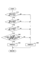
- FIG. It is a flowchart which shows a collision mitigation process. It is a flowchart which shows an operation
- a collision mitigation device 1 shown in FIG. 1 is mounted on a host vehicle and has a function of mitigating a collision between the host vehicle and a preceding vehicle traveling in front of the host vehicle by the operation of a controlled object.
- the collision mitigation apparatus 1 includes a camera target recognition processing unit 11, a millimeter wave target recognition processing unit 12, a vehicle state input unit 13, an FSN calculation unit 14, and a pre-crash safety system (hereinafter PCS) 15. And a controlled object 16.
- PCS pre-crash safety system
- the camera target recognition processing unit 11 performs image recognition of a preceding vehicle traveling in front of the host vehicle based on a captured image obtained by capturing an image of the front of the host vehicle with an image sensor (not shown).
- the image sensor includes, for example, a CCD camera disposed near the center on the front side of the host vehicle, and performs an image capturing range by performing well-known image processing such as template matching on the image data captured by the CCD camera. This is a well-known configuration for detecting a predetermined target (vehicle, pedestrian, etc.) existing inside. Then, the image sensor transmits information on the image target detected by this process to the camera target recognition processing unit 11 as image target information.
- the image target information includes at least information about the type, size, and position (distance, azimuth) of the detected image target.
- the camera target recognition processing unit 11 is an example of an image recognition unit of the present invention.
- the millimeter wave target recognition processing unit 12 radiates a radar wave from a radar sensor (not shown) toward the front of the host vehicle, and receives the reflected wave reflected by the target on the own vehicle. Radar recognition of a preceding vehicle traveling in front of the vehicle is performed.
- the radar sensor for example, irradiates a target object existing in front of the host vehicle with a directional electromagnetic wave and receives the reflected wave, whereby the distance to the target object and the lateral position of the target object ( Or a known millimeter wave radar or the like that can detect the relative speed of the object with respect to the host vehicle, and recognizes the type, shape, position, and the like of the object.
- the millimeter wave target recognition processing unit 12 is an example of a radar recognition unit of the present invention.
- the vehicle state input unit 13 inputs the traveling speed of the host vehicle detected by a vehicle speed sensor (not shown) and the radius of curvature (estimated R) of the traveling curve of the host vehicle detected by a yaw rate sensor (not shown) as the vehicle state of the host vehicle.
- the vehicle speed sensor is a known configuration that detects the vehicle speed based on the rotation speed of the wheels of the vehicle.
- the yaw rate sensor has a known configuration for detecting the turning angular velocity of the host vehicle.
- the vehicle state input unit 13 is an example of a state detection unit of the present invention.
- the FSN calculation unit 14 calculates the position of the preceding vehicle based on the image recognition result of the preceding vehicle by the camera target recognition processing unit 11 and the radar recognition result of the preceding vehicle by the millimeter wave target recognition processing unit 12. Specifically, the FSN calculation unit 14 combines the detection results of the two in order to complement different types of detection errors of the radar sensor and the image sensor, and indicates the position of the combined preceding vehicle (FSN). Compute information.
- the FSN calculation unit 14 is data related to the same preceding vehicle. It is certified that. Using this certified data, the lateral and vertical positions of the preceding vehicle based on the relative distance detected by the radar sensor and the direction of the preceding vehicle based on the lateral and vertical positions detected by the image sensor. Is calculated.
- the FSN information generated in this way is output to the PCS 15 as information with higher object position detection accuracy than information detected by the radar sensor alone or the image sensor alone. Independently of this, position detection information as a detection result by the radar sensor alone and the image sensor alone is also output to the PCS 15. These FSN information and each position detection information are determined so as to be output for each predetermined cycle.
- the FSN calculation unit 14 is an example of the position calculation unit of the present invention.
- PCS15 is comprised as a known computer provided with CPU, ROM, RAM, etc.
- the PCS 15 executes various types of processing such as collision mitigation processing and determination diagnosis processing described later by executing a program stored in the ROM. Further, the PCS 15 performs such processing, and operates the controlled object 16 according to the processing results of these processing.
- the PCS 15 includes a PCS diagnostic detection unit 15A, an operation determination calculation unit 15B, an operation determination diagnosis unit 15C, and a control processing unit 15D as functional configurations.
- the operation determination calculation unit 15B and the operation determination diagnosis unit 15C constitute an operation determination circuit (JDG).
- the PCS diagnosis detection unit 15A detects a diagnosis signal (abnormality generation signal) output from the PCS 15 itself when an abnormality occurs in the PCS 15.
- the operation determination calculation unit 15B determines whether or not to operate the controlled object 16. Specifically, when the PCS diagnosis detection unit 15A does not detect a diagnosis signal, the operation determination calculation unit 15B calculates the calculation result (FSN information) by the FSN calculation unit 14 and the vehicle state input unit 13 and Based on the vehicle state of the vehicle, an operation determination for determining whether to operate the controlled object 16 is performed. For this reason, the operation determination calculation part 15B performs the operation determination calculation (main flow logic) mentioned later.
- the operation determination diagnosis unit 15C diagnoses that the operation determination by the operation determination calculation unit 15B has been appropriately performed. Therefore, the operation determination diagnosis unit 15C executes an operation determination diagnosis (diagnosis logic) described later.
- the control processing unit 15D executes control of the controlled object 16 based on the operation determination by the operation determination calculating unit 15B according to the diagnosis result by the operation determination diagnosis unit 15C. Specifically, when the operation determination diagnosing unit 15C diagnoses that the operation determination by the operation determination calculating unit 15B is properly performed, the control processing unit 15D performs the processing based on the operation determination by the operation determining calculating unit 15B. The control object 16 is allowed to be controlled. On the other hand, when the operation determination diagnosis unit 15C diagnoses that the operation determination by the operation determination calculation unit 15B has not been properly performed, the control processing unit 15D performs control based on the operation determination by the operation determination calculation unit 15B. 16 is not allowed to control.
- the PCS 15 is an example of the signal detection unit, the operation determination calculation unit, the operation determination diagnosis unit, and the control processing unit of the present invention.
- the controlled object 16 has a configuration for mitigating a collision between the host vehicle and a preceding vehicle traveling in front of the host vehicle by its operation.
- Examples of the controlled object 16 include an actuator that drives a brake, a steering, a seat belt, and the like, and an alarm device that issues an alarm.
- the controlled object 16 is a brake will be described.
- step S110 camera target recognition processing is performed. Specifically, the camera target recognition processing unit 11 performs image recognition of a preceding vehicle that travels ahead of the host vehicle based on a captured image obtained by capturing an image of the front of the host vehicle with an image sensor (not shown). Thereafter, the process proceeds to step S120.
- millimeter wave target recognition processing is performed. Specifically, the millimeter wave target recognition processing unit 12 radiates a radar wave from a radar sensor (not shown) toward the front of the host vehicle and receives the reflected wave reflected by the target. Based on the result, radar recognition of a preceding vehicle traveling in front of the host vehicle is performed. Thereafter, the process proceeds to step S130.
- a radar sensor not shown
- vehicle state processing is performed. Specifically, the vehicle state input unit 13 determines the vehicle state of the host vehicle as the vehicle state of the host vehicle, the traveling speed of the host vehicle detected by a vehicle speed sensor (not shown), and the radius of curvature of the traveling curve of the host vehicle detected by a yaw rate sensor (not shown). Enter R). Thereafter, the process proceeds to step S140.
- step S140 FSN calculation processing is performed. Specifically, the FSN calculation unit 14 calculates the position of the preceding vehicle based on the image recognition result of the preceding vehicle by the camera target recognition processing unit 11 and the radar recognition result of the preceding vehicle by the millimeter wave target recognition processing unit 12. To do. Thereafter, the process proceeds to step S150.
- step S150 system status detection is performed. Specifically, the PCS diagnostic detection unit 15A detects a diagnostic signal output from the PCS 15 itself when an abnormality occurs in the PCS 15. Thereafter, the process proceeds to step S160.
- step S160 an operation determination calculation (main flow logic) is performed. That is, when the operation determination calculation unit 15B does not detect the diagnosis signal by the PCS diagnosis detection unit 15A, the calculation result (FSN information) by the FSN calculation unit 14 and the vehicle of the host vehicle input by the vehicle state input unit 13 Based on the state, an operation determination for determining whether to operate the controlled object 16 is performed.
- the details of the operation determination calculation (main flow logic) will be described later.
- a numerical value “1” operation instruction
- an operation determination result when it is determined that the controlled object 16 is not to be operated.
- a numerical value “0” is output. Thereafter, the process proceeds to step S170.
- step S170 an operation determination diagnosis (diagnosis logic) is performed. Specifically, the operation determination diagnosis unit 15C diagnoses that the operation determination by the operation determination calculation unit 15B has been appropriately performed. The details of the operation determination diagnosis (diagnostic logic) will be described later.
- the numerical value “1” is output as the operation determination result when it is diagnosed that the operation determination by the operation determination calculation unit 15B is properly performed, and the operation determination by the operation determination calculation unit 15B is not properly performed.
- a numerical value “0” is output as the operation determination result in the case of diagnosis. Thereafter, the process proceeds to step S180.
- step S180 it is determined whether or not the operation determination result of the operation determination calculation (main flow logic) and the operation determination result of the operation determination diagnosis (diagnostic logic) match.
- the control processing unit 15D compares the operation determination result by the operation determination calculation (main flow logic) in step S160 with the operation determination result by the operation determination diagnosis (diagnosis logic) in step S170. If both match with the numerical value “1” or the numerical value “0”, the determination is affirmative. If one of the numerical values is “1” and the other is the numerical value “0”, the determination is negative. If the determination is affirmative (S180: YES), the process proceeds to step S190. On the other hand, when it is negative determination (S180: NO), it transfers to step S200.
- step S190 the result of the operation determination calculation (main flow logic) is transmitted to subsequent processing. Specifically, when it is determined in step S180 that the operation determination result of the operation determination calculation (main flow logic) matches the operation determination result of the operation determination diagnosis (diagnostic logic), in step S160. Control of the controlled object 16 is permitted based on the operation determination result by the operation determination calculation (main flow logic), and the operation determination result by the operation determination calculation (main flow logic) in step S160 is a control process as a subsequent process. It is sent to the control process of the controlled object 16 by the unit 15D. As a result, when the operation determination result by the operation determination calculation (main flow logic) in step S160 is “1”, the controlled object 16 is operated. In addition, when the operation determination result by the operation determination calculation (main flow logic) in step S160 is a numerical value “0”, the controlled object 16 is not operated. Then return.
- step S200 the result of the operation determination calculation (main flow logic) is not transmitted to subsequent processing. Specifically, when it is determined in step S180 that the operation determination result of the operation determination calculation (main flow logic) does not match the operation determination result of the operation determination diagnosis (diagnostic logic), in step S160. It is not permitted to control the controlled object 16 based on the operation determination result by the operation determination calculation (main flow logic), and the operation determination result by the operation determination calculation (main flow logic) in step S160 is control as the subsequent process. It is not sent to the control process of the controlled object 16 by the processing unit 15D.
- step S160 even if the operation determination result by the operation determination calculation (main flow logic) in step S160 is the numerical value “1”, the operation determination result by the operation determination diagnosis (diagnostic logic) in step S170 is the numerical value “0”. Therefore, the controlled object 16 is not actuated. Further, the controlled object 16 is not operated even when the operation determination result by the operation determination calculation (main flow logic) in step S160 is the numerical value “0”. Then return.
- step S210 it is determined whether or not the vehicle speed satisfies a predetermined condition. Specifically, the operation determination calculation unit 15B determines whether or not the traveling speed of the host vehicle input by the vehicle state input unit 13 satisfies a predetermined condition. Note that the predetermined condition is set in advance by an experiment or the like. When it is affirmation determination (S210: YES), it transfers to step S220. On the other hand, when it is negative determination (S210: NO), it transfers to step S260.
- step S220 it is determined whether or not the estimated R satisfies a predetermined condition. Specifically, the operation determination calculation unit 15B determines whether the radius of curvature (estimated R) of the traveling curve of the host vehicle input by the vehicle state input unit 13 satisfies a predetermined condition. Note that the predetermined condition is set in advance by an experiment or the like. If the determination is affirmative (S220: YES), the process proceeds to step S230. On the other hand, when it is negative determination (S220: NO), it transfers to step S260.
- step S230 it is determined whether the diagnosis satisfies a predetermined condition. Specifically, if the PCS diagnostic detection unit 15A does not detect a diagnosis signal output from the PCS 15 itself when an abnormality occurs in the PCS 15, the operation determination calculation unit 15B makes an affirmative determination, and the diagnosis signal is transmitted to the PCS. When the diagnosis detection unit 15A detects, the operation determination calculation unit 15B makes a negative determination. When it is affirmation determination (S230: YES), it transfers to step S240. On the other hand, when it is negative determination (S230: NO), it transfers to step S260.
- step S240 it is determined whether or not the sensor signal satisfies a predetermined condition. Specifically, when all the sensor signals satisfy the predetermined condition, the operation determination calculation unit 15B makes an affirmative determination, and when any one of the sensor signals does not satisfy the predetermined condition, the operation determination calculation unit 15B makes a negative determination. Examples of the sensor signal include an FSN distance, an FSN lateral position, a sensor distance, and a sensor lateral position. The determination process regarding each sensor signal will be described later. If the determination is affirmative (S240: YES), the process proceeds to step S250. On the other hand, when it is negative determination (S240: NO), it transfers to step S260.
- step S250 the operation determination is ON. Specifically, the operation determination calculation unit 15B determines that the controlled object 16 needs to be operated, and outputs a numerical value “1” as the operation determination result. Then return.
- step S260 the operation determination is OFF. Specifically, the operation determination calculation unit 15B determines that it is not necessary to operate the controlled object 16, determines that the operation determination by the operation determination calculation unit 15B has not been properly performed, and sets the numerical value “ "0" is output. Then return.
- step S310 it is determined whether or not the operation determination of the operation determination calculation (main flow logic) is on. Specifically, the operation determination diagnosis unit 15C determines whether the operation determination by the operation determination calculation unit 15B of the PCS 15 is on. If the determination is affirmative (S310: YES), the process proceeds to step S320. On the other hand, when it is negative determination (S310: NO), it transfers to step S370.
- the operation determination diagnosis unit 15C determines whether the operation determination by the operation determination calculation unit 15B of the PCS 15 is on. If the determination is affirmative (S310: YES), the process proceeds to step S320. On the other hand, when it is negative determination (S310: NO), it transfers to step S370.
- step S320 it is determined whether or not the vehicle speed satisfies a predetermined condition. Specifically, the operation determination diagnosis unit 15C determines whether or not the traveling speed of the host vehicle input by the vehicle state input unit 13 satisfies a predetermined condition. Note that the predetermined condition is set in advance by experiments or the like, but it is preferable that the predetermined condition is the same as that in step S210 of the above-described operation determination calculation (main flow logic). If the determination is affirmative (S320: YES), the process proceeds to step S330. On the other hand, when it is negative determination (S320: NO), it transfers to step S370.
- step S330 it is determined whether or not the estimated R satisfies a predetermined condition. Specifically, the operation determination diagnosis unit 15C determines whether or not the radius of curvature (estimated R) of the traveling curve of the host vehicle input by the vehicle state input unit 13 satisfies a predetermined condition.
- the predetermined condition is set in advance by experiments or the like, but it is preferable to set the same condition as that in step S220 of the operation determination calculation (main flow logic) described above.
- it is affirmation determination (S330: YES) it transfers to step S340.
- it is negative determination (S330: NO) it transfers to step S370.
- step S340 it is determined whether or not the diagnosis satisfies a predetermined condition. Specifically, when the PCS diagnostic detection unit 15A does not detect a diagnosis signal output from the PCS 15 itself when an abnormality occurs in the PCS 15, the operation determination diagnosis unit 15C makes an affirmative determination, and the diagnosis signal is transmitted to the PCS. When the diagnosis detection unit 15A detects, the operation determination diagnosis unit 15C makes a negative determination.
- the condition for this determination is preferably the same condition as step S230 of the above-described operation determination calculation (main flow logic).
- it is affirmation determination (S340: YES)
- it is negative determination S340: NO
- step S350 it is determined whether or not the sensor signal satisfies a predetermined condition. Specifically, the operation determination diagnosis unit 15C makes an affirmative determination when all the sensor signals satisfy a predetermined condition, and the operation determination diagnosis unit when any one of the sensor signals does not satisfy the predetermined condition. 15C makes a negative determination. Examples of the sensor signal include an FSN distance, an FSN lateral position, a sensor distance, and a sensor lateral position. The determination process regarding each sensor signal will be described later. When it is affirmation determination (S350: YES), it transfers to step S360. On the other hand, if any one of the sensor signals is a negative determination that does not satisfy the predetermined condition (S350: NO), the process proceeds to step S370.
- step S360 the diagnosis result is set to ON.
- the operation determination diagnosis unit 15C satisfies the above-described determination criteria set from the viewpoint of mitigating the collision between the host vehicle and the preceding vehicle by the operation of the controlled object 16, and the operation determination calculation unit It diagnoses that the operation determination by 15B was performed appropriately, and outputs numerical value "1" as an operation determination result. Then return.
- step S370 the diagnosis result is turned off.
- the operation determination diagnosis unit 15C does not satisfy the above-described determination criteria set from the viewpoint of mitigating the collision between the host vehicle and the preceding vehicle by the operation of the controlled object 16, and the operation determination calculation It is diagnosed that the operation determination by the unit 15B is not properly performed, and a numerical value “0” is output as the operation determination result. Then return.
- the sensor signal includes an FSN distance, an FSN lateral position, a sensor distance, and a sensor lateral position, and whether each sensor signal is appropriate is determined. Below, each sensor signal is demonstrated in order.
- FSN distance The FSN distance is the distance from the host vehicle to the preceding vehicle calculated using both the radar recognition result of the preceding vehicle by the millimeter wave target recognition processing unit 12 and the image recognition result of the preceding vehicle by the camera target recognition processing unit 11. Distance.
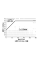
- a graph is set with the relative speed (kph) of the host vehicle relative to the preceding vehicle as the horizontal axis and the distance guard range (m) as the vertical axis.
- a range value is set on the graph based on the operation upper limit distance (m) of the controlled object 16 and the TTC (collision time) upper limit value (Sec).
- the operation upper limit distance is set to 80 m
- the TTC upper limit value is set to 2 Sec.
- the working upper limit distance and the TTC upper limit value are reset according to the target performance.
- the system operation area that is the area in which the system such as the controlled object 16 should be operated is set to the lower right side of the range value on the graph.
- the other region is a system operation prohibition region that is a region in which the system such as the controlled object 16 need not be operated.
- the system operation area of the operation determination diagnosis (diagnostic logic) is set to a wider range than the system operation area of the operation determination calculation (main flow logic) so as not to hinder the processing of the operation determination calculation (main flow logic). It is preferable.
- FIG. 5 illustrates a system operation region and a system operation prohibition region of operation determination diagnosis (diagnostic logic). Further, when the relationship between the FSN distance and the relative speed of the host vehicle with respect to the preceding vehicle is within the system operation region, an affirmative determination is made, and when the relationship is within the system operation prohibition region, a negative determination is made.
- the FSN lateral position is the position of the preceding vehicle relative to the own vehicle calculated using both the radar recognition result of the preceding vehicle by the millimeter wave target recognition processing unit 12 and the image recognition result of the preceding vehicle by the camera target recognition processing unit 11. It is the position in the left-right direction.
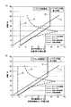
- a graph is set with the horizontal position range (positive) (m) as the horizontal axis and the distance (m) as the vertical axis.
- the detection range of the sensor is plotted on the graph ((1) in the figure).
- a margin is set for the lateral position on the assumption that the host vehicle goes straight ((2) in the figure). In the example shown in FIG. 6A, this margin is set to ⁇ 6 m.
- a value obtained by adding the margin to the lateral position necessary to detect an object at the maximum distance set by the above-described distance setting with the minimum R based on the road structure ordinance is plotted on the graph (FIG. (3)).
- an area where the detection range is larger than the horizontal position is deleted as an unnecessary area ((4) in the figure), and the remaining area is set as the controlled object 16 or the like. It is set as a system operation area that is an area in which the system should be operated.
- the other region is a system operation prohibition region that is a region in which the system such as the controlled object 16 need not be operated.
- the system operation area of the operation determination diagnosis is set to a wider range than the system operation area of the operation determination calculation (main flow logic) so as not to hinder the processing of the operation determination calculation (main flow logic). It is preferable.
- 6A illustrates a system operation area and a system operation prohibition area of the operation determination diagnosis (diagnostic logic). Further, when the relationship between the FSN lateral position and the distance in the straight line direction from the host vehicle to the preceding vehicle is within the system operation region, an affirmative determination is performed, and when the relationship is within the system operation prohibition region, a negative determination is performed. .
- the sensor distance refers to the preceding vehicle from the own vehicle calculated using either the radar recognition result of the preceding vehicle by the millimeter wave target recognition processing unit 12 or the image recognition result of the preceding vehicle by the camera target recognition processing unit 11. It is the distance to.
- the operation determination calculation main logic
- the operation determination calculation is calculated using either the radar recognition result of the preceding vehicle by the millimeter wave target recognition processing unit 12 or the image recognition result of the preceding vehicle by the camera target recognition processing unit 11.
- the distance from the host vehicle to the preceding vehicle is used as the sensor distance.
- the preceding vehicle is calculated based on the radar recognition result of the preceding vehicle by the millimeter wave target recognition processing unit 12. The distance to the vehicle is used as the sensor distance.
- a graph is set with the relative speed (kph) of the host vehicle relative to the preceding vehicle as the horizontal axis and the distance guard range (m) as the vertical axis.
- a range value is set on the graph based on the operation upper limit distance (m) of the controlled object 16 and the TTC (collision time) upper limit value (Sec).
- the operation upper limit distance is set to 80 m
- the TTC upper limit value is set to 2 Sec.
- the working upper limit distance and the TTC upper limit value are reset according to the target performance.
- the system operation area that is the area in which the system such as the controlled object 16 should be operated is set to the lower right side of the range value on the graph.
- the other region is a system operation prohibition region that is a region in which the system such as the controlled object 16 need not be operated.
- the system operation area of the operation determination diagnosis (diagnostic logic) is set to a wider range than the system operation area of the operation determination calculation (main flow logic) so as not to hinder the processing of the operation determination calculation (main flow logic). It is preferable.
- FIG. 5 illustrates a system operation region and a system operation prohibition region of operation determination diagnosis (diagnostic logic). Furthermore, when the relationship between the sensor distance and the relative speed of the host vehicle with respect to the preceding vehicle is within the system operation region, an affirmative determination is made, and when the relationship is within the system operation prohibition region, a negative determination is made.
- the lateral position of the sensor refers to the preceding vehicle relative to the host vehicle calculated using either the radar recognition result of the preceding vehicle by the millimeter wave target recognition processing unit 12 or the image recognition result of the preceding vehicle by the camera target recognition processing unit 11. It is the position in the left-right direction of the vehicle. Note that the operation determination calculation (main logic) is calculated using either the radar recognition result of the preceding vehicle by the millimeter wave target recognition processing unit 12 or the image recognition result of the preceding vehicle by the camera target recognition processing unit 11. The position in the left-right direction of the preceding vehicle with respect to the subject vehicle is used as the sensor lateral position.
- the own vehicle calculated by using the radar recognition result of the preceding vehicle by the millimeter wave target recognition processing unit 12 is used.
- the position in the left-right direction of the preceding vehicle with respect to the vehicle is used as the sensor lateral position.
- a graph is set with the horizontal position range (positive) (m) as the horizontal axis and the distance (m) as the vertical axis.
- the detection range of the sensor is plotted on the graph ((1) in the figure).
- a margin is set for the lateral position on the assumption that the host vehicle goes straight ((2) in the figure). In the example shown in FIG. 6B, this margin is set to ⁇ 4 m.
- a value obtained by adding the margin to the lateral position necessary to detect an object at the maximum distance set by the above-described distance setting with the minimum R based on the road structure ordinance is plotted on the graph (FIG. (3)).
- an area where the detection range is larger than the horizontal position is deleted as an unnecessary area ((4) in the figure), and the remaining area is set as the controlled object 16 or the like. It is set as a system operation area that is an area in which the system is to be operated.
- the other region is a system operation prohibition region that is a region in which the system such as the controlled object 16 need not be operated.
- the system operation area of the operation determination diagnosis is set to a wider range than the system operation area of the operation determination calculation (main flow logic) so as not to hinder the processing of the operation determination calculation (main flow logic). It is preferable.
- 6B illustrates a system operation region and a system operation prohibition region of the operation determination diagnosis (diagnostic logic). Furthermore, when the relationship between the lateral position of the sensor and the distance in the straight line direction from the host vehicle to the preceding vehicle is within the system operation region, an affirmative determination is made, and when the relationship is within the system operation prohibition region, a negative determination is performed. .
- the collision alleviating apparatus 1 of the present embodiment it is possible to improve the reliability of the operation determination that is a determination as to whether or not the controlled object 16 such as a brake is to be operated. As a result, it is possible to improve the reliability as a system of the collision mitigation apparatus 1 that is mounted on the own vehicle and that mitigates the collision between the own vehicle and a preceding vehicle that travels ahead of the own vehicle by the operation of the controlled object 16. .
- SYMBOLS 1 DESCRIPTION OF SYMBOLS 1 ... Collision mitigation apparatus, 11 ... Camera target recognition process part, 12 ... Millimeter wave target recognition process part, 13 ... Vehicle state input part, 14 ... FSN calculating part, 15 ... Pre-crash safety system (PCS), 15A ... PCS diagnostic detection unit, 15B ... operation determination calculation unit, 15C ... operation determination diagnosis unit, 15D ... control processing unit, 16 ... controlled object.
- PCS Pre-crash safety system
- 15A PCS diagnostic detection unit
- 15B operation determination calculation unit
- 15C operation determination diagnosis unit
- 15D control processing unit
- 16 ... controlled object.
Landscapes
- Engineering & Computer Science (AREA)
- Transportation (AREA)
- Mechanical Engineering (AREA)
- Physics & Mathematics (AREA)
- General Physics & Mathematics (AREA)
- Automation & Control Theory (AREA)
- Chemical & Material Sciences (AREA)
- Combustion & Propulsion (AREA)
- Traffic Control Systems (AREA)
- Radar Systems Or Details Thereof (AREA)
- Valves And Accessory Devices For Braking Systems (AREA)
- Regulating Braking Force (AREA)
Abstract
作動判定演算部15Bは、ダイアグ信号を検出していない場合に、FSN演算部14による算出結果(FSN情報)および車両状態入力部13によって入力された自車両の車両状態に基づき、被制御対象16を作動させるか否かを判定する。作動判定診断部15Cは、作動判定演算部15Bによる作動判定が適切に行われたことを診断する。作動判定演算部15Bによる作動判定が適切に行われたと診断された場合には、当該作動判定に基づいて被制御対象16を制御することを許可する。一方、作動判定演算部15Bによる作動判定が適切に行われなかったと診断された場合には、当該作動判定に基づいて被制御対象16を制御することを許可しない。
Description
本発明は、自車両に搭載され、被制御対象の作動により自車両と自車両の前方を走行する先行車両との衝突を緩和する衝突緩和装置に関する。
特許文献1には、車両のブレーキ装置の制御装置及びその制御方法について記載されている。より具体的には、特許文献1には、(1)制御装置が、第1の階層と第2の階層と第3の階層でそれぞれ演算処理を行う点、(2)第2の階層の処理結果が前記第1の階層に送られ、第1の階層が、送られてきた前記第2の階層の処理結果に基づき前記第2の演算処理の診断を行う点、(3)前記第2の演算処理に異常が生じたと判定した場合には、前記第1の階層が、第1の階層の処理結果を前記第3の階層に送り、第3の階層が、前記第1の階層の処理結果に基づいて処理を行う点、(4)第1の階層が車両の制動力を演算し、前記第2の階層が車両の制動力における摩擦制動力を演算し、前記第3の階層が各車輪に対応した制動力を演算する点、が記載されている。
しかし、上記特許文献1に記載の技術では、第2の演算処理の診断が正しく行われない場合に、ブレーキなどの制動に関するデバイスが不適切なタイミングで作動するおそれがあった。すなわち、上記特許文献1に記載の技術では、デバイスを作動させるか否かの判定である作動判定の信頼性が低いという問題があった。
本発明は、このような課題に鑑みなされたものであり、その目的とするところは、ブレーキなどの被制御対象を作動させるか否かの判定である作動判定の信頼性を向上させることにある。
本発明の衝突緩和装置(1)では、レーダ認識部(12)が、レーダセンサが自車両の前方に向けてレーダ波を照射するとともにその照射したレーダ波が物標によって反射された反射波を受信した結果に基づき自車両の前方を走行する先行車両のレーダ認識を行い、画像認識部(11)が、画像センサが自車両の前方を撮像した撮像画像に基づき自車両の前方を走行する先行車両の画像認識を行う。そして、位置算出部(14)が、前記レーダ認識部(12)による先行車両のレーダ認識結果および前記画像認識部(11)による先行車両の画像認識結果に基づいて先行車両の位置を算出する。また、状態検出部(13)が、自車両の車両状態を検出し、信号検出部(15A)が、当該衝突緩和装置(1)に異常が発生したことを示す異常発生信号を検出する。そして、作動判定演算部(15B)が、前記信号検出部(15A)が異常発生信号を検出していない場合に、前記位置算出部(14)による算出結果および前記状態検出部(13)によって検出された自車両の車両状態に基づき、前記被制御対象(16)を作動させるか否かを判定する作動判定を行う。
さらに、本発明の衝突緩和装置(1)では、作動判定診断部(15C)が、前記作動判定演算部(15B)による前記作動判定が適切に行われたことを診断する。ここで、前記作動判定演算部(15B)による前記作動判定が適切に行われたと前記作動判定診断部(15C)によって診断された場合には、制御処理部(15D)が、前記作動判定に基づいて前記被制御対象(16)を制御することを許可する。一方、前記作動判定演算部(15B)による前記作動判定が適切に行われなかったと前記作動判定診断部(15C)によって診断された場合には、制御処理部(15D)が、前記作動判定に基づいて前記被制御対象(16)を制御することを許可しない。
したがって、本発明の衝突緩和装置(1)によれば、ブレーキなどの被制御対象(16)を作動させるか否かの判定である作動判定の信頼性を向上させることができる。この結果、自車両に搭載され、被制御対象(16)の作動により自車両と自車両の前方を走行する先行車両との衝突を緩和する衝突緩和装置(1)のシステムとしての信頼性を向上させることができる。
以下に本発明の実施形態を図面とともに説明する。なお、本発明は下記実施形態に限定されるものではなく、様々な態様にて実施することが可能である。
[1.衝突緩和装置1の構成の説明]
図1に示す衝突緩和装置1は、自車両に搭載され、被制御対象の作動により自車両と自車両の前方を走行する先行車両との衝突を緩和する機能を有する。
[1.衝突緩和装置1の構成の説明]
図1に示す衝突緩和装置1は、自車両に搭載され、被制御対象の作動により自車両と自車両の前方を走行する先行車両との衝突を緩和する機能を有する。
このため、衝突緩和装置1は、カメラ物標認識処理部11と、ミリ波物標認識処理部12と、車両状態入力部13と、FSN演算部14と、プリクラッシュセーフティシステム(以下PCS)15と、被制御対象16と、を備える。
[1.1.カメラ物標認識処理部11の構成の説明]
カメラ物標認識処理部11は、図示しない画像センサが自車両の前方を撮像した撮像画像に基づき自車両の前方を走行する先行車両の画像認識を行う。なお、画像センサは、例えば、自車両の前側における中央付近に配置されたCCDカメラからなり、CCDカメラで撮像した撮像データに対して、テンプレートマッチング等の周知の画像処理を行うことにより、撮像範囲内に存在する所定の物標(車両、歩行者等)を検出する周知の構成である。そして、画像センサは、この処理により検出された画像物標の情報を画像物標情報としてカメラ物標認識処理部11へ送信する。なお、画像物標情報には、検出した画像物標の種類、大きさ、位置(距離、方位)についての情報が少なくとも含まれている。
なお、カメラ物標認識処理部11は、本発明の画像認識部の一例である。
カメラ物標認識処理部11は、図示しない画像センサが自車両の前方を撮像した撮像画像に基づき自車両の前方を走行する先行車両の画像認識を行う。なお、画像センサは、例えば、自車両の前側における中央付近に配置されたCCDカメラからなり、CCDカメラで撮像した撮像データに対して、テンプレートマッチング等の周知の画像処理を行うことにより、撮像範囲内に存在する所定の物標(車両、歩行者等)を検出する周知の構成である。そして、画像センサは、この処理により検出された画像物標の情報を画像物標情報としてカメラ物標認識処理部11へ送信する。なお、画像物標情報には、検出した画像物標の種類、大きさ、位置(距離、方位)についての情報が少なくとも含まれている。
なお、カメラ物標認識処理部11は、本発明の画像認識部の一例である。
[1.2.ミリ波物標認識処理部12の構成の説明]
ミリ波物標認識処理部12は、図示しないレーダセンサが自車両の前方に向けてレーダ波を照射するとともにその照射したレーダ波が物標によって反射された反射波を受信した結果に基づき自車両の前方を走行する先行車両のレーダ認識を行う。なお、レーダセンサは、例えば、自車両の前方に存在する対象物に対して指向性のある電磁波を照射し、その反射波を受信することによって、対象物までの距離や対象物の横位置(又は方位)、自車両に対する対象物の相対速度を検出可能な周知のミリ波レーダ等として構成されており、対象物の種類、形状及び位置等を認識する。
なお、ミリ波物標認識処理部12は、本発明のレーダ認識部の一例である。
ミリ波物標認識処理部12は、図示しないレーダセンサが自車両の前方に向けてレーダ波を照射するとともにその照射したレーダ波が物標によって反射された反射波を受信した結果に基づき自車両の前方を走行する先行車両のレーダ認識を行う。なお、レーダセンサは、例えば、自車両の前方に存在する対象物に対して指向性のある電磁波を照射し、その反射波を受信することによって、対象物までの距離や対象物の横位置(又は方位)、自車両に対する対象物の相対速度を検出可能な周知のミリ波レーダ等として構成されており、対象物の種類、形状及び位置等を認識する。
なお、ミリ波物標認識処理部12は、本発明のレーダ認識部の一例である。
[1.3.車両状態入力部13の構成の説明]
車両状態入力部13は、自車両の車両状態として、図示しない車速センサが検出した自車両の走行速度、および図示しないヨーレートセンサが検出した自車両の進行曲線の曲率半径(推定R)を入力する。なお、車速センサは、自車両の車輪の回転速度に基づき自車速を検出する周知の構成である。また、ヨーレートセンサは、自車両の旋回角速度を検出する周知の構成である。
なお、車両状態入力部13は、本発明の状態検出部の一例である。
車両状態入力部13は、自車両の車両状態として、図示しない車速センサが検出した自車両の走行速度、および図示しないヨーレートセンサが検出した自車両の進行曲線の曲率半径(推定R)を入力する。なお、車速センサは、自車両の車輪の回転速度に基づき自車速を検出する周知の構成である。また、ヨーレートセンサは、自車両の旋回角速度を検出する周知の構成である。
なお、車両状態入力部13は、本発明の状態検出部の一例である。
[1.4.FSN演算部14の構成の説明]
FSN演算部14は、カメラ物標認識処理部11による先行車両の画像認識結果およびミリ波物標認識処理部12による先行車両のレーダ認識結果に基づいて先行車両の位置を算出する。具体的には、FSN演算部14は、レーダセンサと画像センサとがそれぞれ有する別種の検出誤差を補完するために両者の検出結果を結合し、結合された先行車両の位置を示すフュージョン(FSN)情報を演算する。
FSN演算部14は、カメラ物標認識処理部11による先行車両の画像認識結果およびミリ波物標認識処理部12による先行車両のレーダ認識結果に基づいて先行車両の位置を算出する。具体的には、FSN演算部14は、レーダセンサと画像センサとがそれぞれ有する別種の検出誤差を補完するために両者の検出結果を結合し、結合された先行車両の位置を示すフュージョン(FSN)情報を演算する。
より具体的には、FSN演算部14は、例えばレーダセンサおよび画像センサによりそれぞれ検出された先行車両の位置が、予め定められた許容誤差範囲内にある場合に、両者が同一の先行車両に関するデータであると認定する。この認定されたデータを用いて、レーダセンサにより検出された相対距離と、画像センサにより検出された横位置および縦位置に基づく先行車両の方向と、を基にして先行車両の横位置および縦位置を演算する。
こうして生成されたFSN情報は、レーダセンサ単体あるいは画像センサ単体で検出された情報よりも、物体の位置検出精度が高い情報として、PCS15へ出力される。また、これとは独立して、レーダセンサ単体および画像センサ単体による検出結果としての位置検出情報もそれぞれPCS15へ出力される。これらのFSN情報および各位置検出情報は、それぞれ個別の所定サイクル毎に出力されるように定められている。
なお、FSN演算部14は、本発明の位置算出部の一例である。
なお、FSN演算部14は、本発明の位置算出部の一例である。
[1.5.PCS15の構成の説明]
PCS15は、CPU、ROM、RAM等を備えた周知のコンピュータとして構成されている。そして、PCS15は、ROMに格納されたプログラムを実行することによって、後述する衝突緩和処理や判定診断処理などの各種処理を実施する。さらに、PCS15は、このような処理を実施し、これらの処理による処理結果に応じて被制御対象16を作動させる。
PCS15は、CPU、ROM、RAM等を備えた周知のコンピュータとして構成されている。そして、PCS15は、ROMに格納されたプログラムを実行することによって、後述する衝突緩和処理や判定診断処理などの各種処理を実施する。さらに、PCS15は、このような処理を実施し、これらの処理による処理結果に応じて被制御対象16を作動させる。
また、PCS15は、機能上の構成として、PCSダイアグ検出部15Aと、作動判定演算部15Bと、作動判定診断部15Cと、制御処理部15Dと、を備える。なお、このうちの作動判定演算部15Bおよび作動判定診断部15Cが作動判定回路(JDG)を構成する。
PCSダイアグ検出部15Aは、PCS15に異常が発生した場合にPCS15自身から出力されるダイアグ信号(異常発生信号)を検出する。
作動判定演算部15Bは、被制御対象16を作動させるか否かを判定する。具体的には、作動判定演算部15Bは、PCSダイアグ検出部15Aがダイアグ信号を検出していない場合に、FSN演算部14による算出結果(FSN情報)および車両状態入力部13によって入力された自車両の車両状態に基づき、被制御対象16を作動させるか否かを判定する作動判定を行う。このため、作動判定演算部15Bは、後述する作動判定演算(本流ロジック)を実行する。
作動判定演算部15Bは、被制御対象16を作動させるか否かを判定する。具体的には、作動判定演算部15Bは、PCSダイアグ検出部15Aがダイアグ信号を検出していない場合に、FSN演算部14による算出結果(FSN情報)および車両状態入力部13によって入力された自車両の車両状態に基づき、被制御対象16を作動させるか否かを判定する作動判定を行う。このため、作動判定演算部15Bは、後述する作動判定演算(本流ロジック)を実行する。
作動判定診断部15Cは、作動判定演算部15Bによる作動判定が適切に行われたことを診断する。このため、作動判定診断部15Cは、後述する作動判定診断(診断ロジック)を実行する。
制御処理部15Dは、作動判定診断部15Cによる診断結果に応じて、作動判定演算部15Bによる作動判定に基づく被制御対象16の制御を実行する。具体的には、作動判定演算部15Bによる作動判定が適切に行われたと作動判定診断部15Cによって診断された場合には、制御処理部15Dは、作動判定演算部15Bによる作動判定に基づいて被制御対象16を制御することを許可する。一方、作動判定演算部15Bによる作動判定が適切に行われなかったと作動判定診断部15Cによって診断された場合には、制御処理部15Dは、作動判定演算部15Bによる作動判定に基づいて被制御対象16を制御することを許可しない。
なお、PCS15は、本発明の信号検出部、作動判定演算部、作動判定診断部および制御処理部の一例である。
なお、PCS15は、本発明の信号検出部、作動判定演算部、作動判定診断部および制御処理部の一例である。
[1.6.被制御対象16の構成の説明]
被制御対象16は、その作動により自車両と自車両の前方を走行する先行車両との衝突を緩和するための構成である。なお、被制御対象16としては、例えば、ブレーキや、ステアリング、シートベルト等を駆動するアクチュエータや、警報を発する警報装置等が挙げられる。以下、本実施形態においては、被制御対象16がブレーキである場合について説明する。
被制御対象16は、その作動により自車両と自車両の前方を走行する先行車両との衝突を緩和するための構成である。なお、被制御対象16としては、例えば、ブレーキや、ステアリング、シートベルト等を駆動するアクチュエータや、警報を発する警報装置等が挙げられる。以下、本実施形態においては、被制御対象16がブレーキである場合について説明する。
[2.衝突緩和処理の説明]
次に、衝突緩和装置1が実行する衝突緩和処理を、図2のフローチャートを参照して説明する。
次に、衝突緩和装置1が実行する衝突緩和処理を、図2のフローチャートを参照して説明する。
本処理は、衝突緩和装置1の電源状態がオンである場合に実行される。
まず、最初のステップS110では、カメラ物標認識処理を行う。具体的には、カメラ物標認識処理部11が、図示しない画像センサが自車両の前方を撮像した撮像画像に基づき自車両の前方を走行する先行車両の画像認識を行う。その後、ステップS120に移行する。
まず、最初のステップS110では、カメラ物標認識処理を行う。具体的には、カメラ物標認識処理部11が、図示しない画像センサが自車両の前方を撮像した撮像画像に基づき自車両の前方を走行する先行車両の画像認識を行う。その後、ステップS120に移行する。
S120では、ミリ波物標認識処理を行う。具体的には、ミリ波物標認識処理部12が、図示しないレーダセンサが自車両の前方に向けてレーダ波を照射するとともにその照射したレーダ波が物標によって反射された反射波を受信した結果に基づき自車両の前方を走行する先行車両のレーダ認識を行う。その後、ステップS130に移行する。
S130では、車両状態処理を行う。具体的には、車両状態入力部13が、自車両の車両状態として、図示しない車速センサが検出した自車両の走行速度、および図示しないヨーレートセンサが検出した自車両の進行曲線の曲率半径(推定R)を入力する。その後、ステップS140に移行する。
ステップS140では、FSN演算処理を行う。具体的には、FSN演算部14が、カメラ物標認識処理部11による先行車両の画像認識結果およびミリ波物標認識処理部12による先行車両のレーダ認識結果に基づいて先行車両の位置を算出する。その後、ステップS150に移行する。
ステップS150では、システム状態検知を行う。具体的には、PCSダイアグ検出部15Aが、PCS15に異常が発生した場合にPCS15自身から出力されるダイアグ信号を検出する。その後、ステップS160に移行する。
ステップS160では、作動判定演算(本流ロジック)を行う。すなわち、作動判定演算部15Bが、PCSダイアグ検出部15Aがダイアグ信号を検出していない場合に、FSN演算部14による算出結果(FSN情報)および車両状態入力部13によって入力された自車両の車両状態に基づき、被制御対象16を作動させるか否かを判定する作動判定を行う。なお、作動判定演算(本流ロジック)の詳細については後述する。ここでは、被制御対象16を作動させると判定された場合の作動判定結果としては、数値「1」(作動指示)が出力され、被制御対象16を作動させないと判定された場合の作動判定結果としては、数値「0」が出力される。その後、ステップS170に移行する。
ステップS170では、作動判定診断(診断ロジック)を行う。具体的には、作動判定診断部15Cが、作動判定演算部15Bによる作動判定が適切に行われたことを診断する。なお、作動判定診断(診断ロジック)の詳細については後述する。ここでは、作動判定演算部15Bによる作動判定が適切に行われたと診断した場合の作動判定結果としては、数値「1」が出力され、作動判定演算部15Bによる作動判定が適切に行われなかったと診断した場合の作動判定結果としては、数値「0」が出力される。その後、ステップS180に移行する。
ステップS180では、作動判定演算(本流ロジック)の作動判定結果と作動判定診断(診断ロジック)の作動判定結果とは一致しているか否かを判断する。具体的には、制御処理部15Dが、ステップS160での作動判定演算(本流ロジック)による作動判定結果とステップS170での作動判定診断(診断ロジック)による作動判定結果とを比較する。双方が数値「1」または数値「0」で一致する場合には肯定判断となり、一方が数値「1」であり他方が数値「0」であるといった具合に一致しない場合には否定判断となる。肯定判断である場合には(S180:YES)、ステップS190に移行する。一方、否定判断である場合には(S180:NO)、ステップS200に移行する。
ステップS190では、作動判定演算(本流ロジック)の結果を後段の処理に送信する。具体的には、ステップS180にて作動判定演算(本流ロジック)の作動判定結果と作動判定診断(診断ロジック)の作動判定結果とが一致していると判断されたことを受けて、ステップS160での作動判定演算(本流ロジック)による作動判定結果に基づいて被制御対象16を制御することが許可され、ステップS160での作動判定演算(本流ロジック)による作動判定結果が後段の処理としての制御処理部15Dによる被制御対象16の制御処理に送られる。この結果、ステップS160での作動判定演算(本流ロジック)による作動判定結果が数値「1」である場合には、被制御対象16を作動させることになる。また、ステップS160での作動判定演算(本流ロジック)による作動判定結果が数値「0」である場合には、被制御対象16を作動させないことになる。その後、リターンする。
ステップS200では、作動判定演算(本流ロジック)の結果を後段の処理に送信しないこととする。具体的には、ステップS180にて作動判定演算(本流ロジック)の作動判定結果と作動判定診断(診断ロジック)の作動判定結果とが一致していないと判断されたことを受けて、ステップS160での作動判定演算(本流ロジック)による作動判定結果に基づいて被制御対象16を制御することが許可されず、ステップS160での作動判定演算(本流ロジック)による作動判定結果が後段の処理としての制御処理部15Dによる被制御対象16の制御処理には送られない。この結果、ステップS160での作動判定演算(本流ロジック)による作動判定結果が数値「1」である場合であっても、ステップS170での作動判定診断(診断ロジック)による作動判定結果が数値「0」であるため、被制御対象16を作動させないことになる。また、ステップS160での作動判定演算(本流ロジック)による作動判定結果が数値「0」である場合にも、被制御対象16を作動させないことになる。その後、リターンする。
[2.1.作動判定演算(本流ロジック)の説明]
次に、衝突緩和装置1が実行する作動判定演算(本流ロジック)を、図3のフローチャートを参照して説明する。
次に、衝突緩和装置1が実行する作動判定演算(本流ロジック)を、図3のフローチャートを参照して説明する。
本処理は、上記衝突緩和処理中のステップS160に移行した際にステップS160のサブルーチンとして実行される。
まず、最初のステップS210では、車速が所定条件を満たしているか否かを判断する。具体的には、作動判定演算部15Bが、車両状態入力部13によって入力された自車両の走行速度が所定条件を満たしているか否かを判断する。なお、所定条件については、予め実験等によって設定される。肯定判断である場合には(S210:YES)、ステップS220に移行する。一方、否定判断である場合には(S210:NO)、ステップS260に移行する。
まず、最初のステップS210では、車速が所定条件を満たしているか否かを判断する。具体的には、作動判定演算部15Bが、車両状態入力部13によって入力された自車両の走行速度が所定条件を満たしているか否かを判断する。なお、所定条件については、予め実験等によって設定される。肯定判断である場合には(S210:YES)、ステップS220に移行する。一方、否定判断である場合には(S210:NO)、ステップS260に移行する。
ステップS220では、推定Rが所定条件を満たしているか否かを判断する。具体的には、作動判定演算部15Bが、車両状態入力部13によって入力された自車両の進行曲線の曲率半径(推定R)が所定条件を満たしているか否かを判断する。なお、所定条件については、予め実験等によって設定される。肯定判断である場合には(S220:YES)、ステップS230に移行する。一方、否定判断である場合には(S220:NO)、ステップS260に移行する。
ステップS230では、ダイアグが所定条件を満たしているか否かを判断する。具体的には、PCS15に異常が発生した場合にPCS15自身から出力されるダイアグ信号をPCSダイアグ検出部15Aが検出していない場合には作動判定演算部15Bが肯定判断を行い、ダイアグ信号をPCSダイアグ検出部15Aが検出した場合には、作動判定演算部15Bが否定判断を行う。肯定判断である場合には(S230:YES)、ステップS240に移行する。一方、否定判断である場合には(S230:NO)、ステップS260に移行する。
ステップS240では、センサ信号が所定条件を満たしているか否かを判断する。具体的には、センサ信号すべてが所定条件を満たしている場合には作動判定演算部15Bが肯定判断を行い、センサ信号の何れか一つでも所定条件を満たしていない場合には作動判定演算部15Bが否定判断を行う。このセンサ信号としては、FSN距離、FSN横位置、センサ距離およびセンサ横位置が挙げられる。各センサ信号に関する判断処理については後述する。肯定判断である場合には(S240:YES)、ステップS250に移行する。一方、否定判断である場合には(S240:NO)、ステップS260に移行する。
ステップS250では、作動判定ONとする。具体的には、作動判定演算部15Bが、被制御対象16を作動させる必要があると判断し、作動判定結果として数値「1」を出力する。その後、リターンする。
ステップS260では、作動判定OFFとする。具体的には、作動判定演算部15Bが、被制御対象16を作動させる必要が無いと判断し、作動判定演算部15Bによる作動判定が適切に行われなかったと判断し、作動判定結果として数値「0」を出力する。その後、リターンする。
[2.2.作動判定診断(診断ロジック)の説明]
次に、衝突緩和装置1が実行する作動判定診断(診断ロジック)を、図4のフローチャートを参照して説明する。
次に、衝突緩和装置1が実行する作動判定診断(診断ロジック)を、図4のフローチャートを参照して説明する。
本処理は、上記衝突緩和処理中のステップS170に移行した際にステップS170のサブルーチンとして実行される。
まず、最初のステップS310では、作動判定演算(本流ロジック)の作動判定がオンになっているか否かを判断する。具体的には、作動判定診断部15Cが、PCS15の作動判定演算部15Bによる作動判定がオンになっているか否かを判断する。肯定判断である場合には(S310:YES)、ステップS320に移行する。一方、否定判断である場合には(S310:NO)、ステップS370に移行する。
まず、最初のステップS310では、作動判定演算(本流ロジック)の作動判定がオンになっているか否かを判断する。具体的には、作動判定診断部15Cが、PCS15の作動判定演算部15Bによる作動判定がオンになっているか否かを判断する。肯定判断である場合には(S310:YES)、ステップS320に移行する。一方、否定判断である場合には(S310:NO)、ステップS370に移行する。
ステップS320では、車速が所定条件を満たしているか否かを判断する。具体的には、作動判定診断部15Cが、車両状態入力部13によって入力された自車両の走行速度が所定条件を満たしているか否かを判断する。なお、所定条件については、予め実験等によって設定されるが、上述の作動判定演算(本流ロジック)のステップS210と同等の条件とすることが好ましい。肯定判断である場合には(S320:YES)、ステップS330に移行する。一方、否定判断である場合には(S320:NO)、ステップS370に移行する。
ステップS330では、推定Rが所定条件を満たしているか否かを判断する。具体的には、作動判定診断部15Cが、車両状態入力部13によって入力された自車両の進行曲線の曲率半径(推定R)が所定条件を満たしているか否かを判断する。なお、所定条件については、予め実験等によって設定されるが、上述の作動判定演算(本流ロジック)のステップS220と同等の条件とすることが好ましい。肯定判断である場合には(S330:YES)、ステップS340に移行する。一方、否定判断である場合には(S330:NO)、ステップS370に移行する。
ステップS340では、ダイアグが所定条件を満たしているか否かを判断する。具体的には、PCS15に異常が発生した場合にPCS15自身から出力されるダイアグ信号をPCSダイアグ検出部15Aが検出していない場合には作動判定診断部15Cが肯定判断を行い、ダイアグ信号をPCSダイアグ検出部15Aが検出した場合には作動判定診断部15Cが否定判断を行う。この判断のための条件は、上述の作動判定演算(本流ロジック)のステップS230と同等の条件とすることが好ましい。肯定判断である場合には(S340:YES)、ステップS350に移行する。一方、否定判断である場合には(S340:NO)、ステップS370に移行する。
ステップS350では、センサ信号が所定条件を満たしているか否かを判断する。具体的には、センサ信号すべてが所定条件を満たしている場合には作動判定診断部15Cが肯定判断を行い、センサ信号の何れか一つでも所定条件を満たしていない場合には作動判定診断部15Cが否定判断を行う。このセンサ信号としては、FSN距離、FSN横位置、センサ距離およびセンサ横位置が挙げられる。各センサ信号に関する判断処理については後述する。肯定判断である場合には(S350:YES)、ステップS360に移行する。一方、センサ信号の何れか一つでも所定条件を満たしていない否定判断である場合には(S350:NO)、ステップS370に移行する。
ステップS360では、診断結果を作動判定ONとする。具体的には、作動判定診断部15Cが、被制御対象16の作動により自車両と先行車両との衝突を緩和する観点から設定される上述のような判断基準を満たしており、作動判定演算部15Bによる作動判定が適切に行われたと診断し、作動判定結果として数値「1」を出力する。その後、リターンする。
ステップS370では、診断結果を作動判定OFFとする。具体的には、作動判定診断部15Cが、被制御対象16の作動により自車両と先行車両との衝突を緩和する観点から設定される上述のような判断基準を満たしておらず、作動判定演算部15Bによる作動判定が適切に行われなかったと診断し、作動判定結果として数値「0」を出力する。その後、リターンする。
[2.3.各センサ信号に関する判断処理の説明]
次に、各センサ信号に関する判断処理を、図5および図6を参照して説明する。
本処理は、作動判定演算(本流ロジック)中のステップS240に移行した際、および作動判定診断(診断ロジック)中のステップS350に移行した際に実行される。センサ信号としては、FSN距離、FSN横位置、センサ距離およびセンサ横位置があり、各センサ信号について適否判断が行われる。以下に、各センサ信号について順に説明する。
次に、各センサ信号に関する判断処理を、図5および図6を参照して説明する。
本処理は、作動判定演算(本流ロジック)中のステップS240に移行した際、および作動判定診断(診断ロジック)中のステップS350に移行した際に実行される。センサ信号としては、FSN距離、FSN横位置、センサ距離およびセンサ横位置があり、各センサ信号について適否判断が行われる。以下に、各センサ信号について順に説明する。
(1)FSN距離:
FSN距離とは、ミリ波物標認識処理部12による先行車両のレーダ認識結果およびカメラ物標認識処理部11による先行車両の画像認識結果の双方を用いて算出された自車両から先行車両までの距離である。
FSN距離とは、ミリ波物標認識処理部12による先行車両のレーダ認識結果およびカメラ物標認識処理部11による先行車両の画像認識結果の双方を用いて算出された自車両から先行車両までの距離である。
まず、図5に例示するように、自車両の先行車両に対する相対速度(kph)を横軸、距離ガード範囲(m)を縦軸とするグラフを設定する。次に、グラフ上に、被制御対象16の作動上限距離(m)とTTC(衝突時間)上限値(Sec)とに基づいて範囲値を設定する。例えば、作動上限距離を80mに設定するとともに、TTC上限値を2Secに設定する。なお、目標性能に応じて作動上限距離およびTTC上限値を再設定する。そして、被制御対象16などのシステムを作動させるべき領域であるシステム作動領域をグラフ上の範囲値よりも右下側に設定する。それ以外の領域は被制御対象16などのシステムを作動させなくてもよい領域であるシステム作動禁止領域とする。ここで、作動判定診断(診断ロジック)のシステム作動領域は、作動判定演算(本流ロジック)の処理を阻害しないために、作動判定演算(本流ロジック)のシステム作動領域よりも広い範囲に設定されることが好ましい。図5では、作動判定診断(診断ロジック)のシステム作動領域およびシステム作動禁止領域が例示されている。さらに、FSN距離と自車両の先行車両に対する相対速度との関係が、システム作動領域内にある場合には肯定判断を行い、システム作動禁止領域内にある場合には否定判断を行う。
(2)FSN横位置:
FSN横位置とは、ミリ波物標認識処理部12による先行車両のレーダ認識結果およびカメラ物標認識処理部11による先行車両の画像認識結果の双方を用いて算出された自車両に対する先行車両の左右方向の位置である。
FSN横位置とは、ミリ波物標認識処理部12による先行車両のレーダ認識結果およびカメラ物標認識処理部11による先行車両の画像認識結果の双方を用いて算出された自車両に対する先行車両の左右方向の位置である。
図6(a)に例示するように、横位置範囲(正)(m)を横軸、距離(m)を縦軸とするグラフを設定する。次に、センサの検知範囲をグラフ上にプロットする(図中の(1))。そして、自車両が直進することを前提とした横位置のマージンを設定する(図中の(2))。図6(a)に示す例では、このマージンを±6mに設定している。さらに、車速毎に、道路構造令に基づく最小Rで、前述の距離設定で設定した最大距離における物体を検知するのに必要な横位置に上記マージンを加算した値をグラフ上にプロットする(図中の(3))。さらに、上記検知範囲が上記横位置よりも大きくなる領域(図では40m以上となる領域)を不要な領域として削除し(図中の(4))、残りの領域を、被制御対象16などのシステムを作動させるべき領域であるシステム作動領域として設定する。それ以外の領域は被制御対象16などのシステムを作動させなくてもよい領域であるシステム作動禁止領域とする。ここで、作動判定診断(診断ロジック)のシステム作動領域は、作動判定演算(本流ロジック)の処理を阻害しないために、作動判定演算(本流ロジック)のシステム作動領域よりも広い範囲に設定されることが好ましい。図6(a)では、作動判定診断(診断ロジック)のシステム作動領域およびシステム作動禁止領域が例示されている。さらに、FSN横位置と自車両から先行車両までの直進方向の距離との関係が、システム作動領域内にある場合には肯定判断を行い、システム作動禁止領域内にある場合には否定判断を行う。
(3)センサ距離:
センサ距離とは、ミリ波物標認識処理部12による先行車両のレーダ認識結果またはカメラ物標認識処理部11による先行車両の画像認識結果の何れか一方を用いて算出された自車両から先行車両までの距離である。なお、作動判定演算(本流ロジック)では、ミリ波物標認識処理部12による先行車両のレーダ認識結果またはカメラ物標認識処理部11による先行車両の画像認識結果の何れか一方を用いて算出された自車両から先行車両までの距離をセンサ距離として用いるが、作動判定診断(診断ロジック)では、ミリ波物標認識処理部12による先行車両のレーダ認識結果を用いて算出された自車両から先行車両までの距離をセンサ距離として用いる。
センサ距離とは、ミリ波物標認識処理部12による先行車両のレーダ認識結果またはカメラ物標認識処理部11による先行車両の画像認識結果の何れか一方を用いて算出された自車両から先行車両までの距離である。なお、作動判定演算(本流ロジック)では、ミリ波物標認識処理部12による先行車両のレーダ認識結果またはカメラ物標認識処理部11による先行車両の画像認識結果の何れか一方を用いて算出された自車両から先行車両までの距離をセンサ距離として用いるが、作動判定診断(診断ロジック)では、ミリ波物標認識処理部12による先行車両のレーダ認識結果を用いて算出された自車両から先行車両までの距離をセンサ距離として用いる。
上述のFSN距離の場合と同じく、図5に例示するように、自車両の先行車両に対する相対速度(kph)を横軸、距離ガード範囲(m)を縦軸とするグラフを設定する。次に、グラフ上に、被制御対象16の作動上限距離(m)とTTC(衝突時間)上限値(Sec)とに基づいて範囲値を設定する。例えば、作動上限距離を80mに設定するとともに、TTC上限値を2Secに設定する。なお、目標性能に応じて作動上限距離およびTTC上限値を再設定する。そして、被制御対象16などのシステムを作動させるべき領域であるシステム作動領域をグラフ上の範囲値よりも右下側に設定する。それ以外の領域は被制御対象16などのシステムを作動させなくてもよい領域であるシステム作動禁止領域とする。ここで、作動判定診断(診断ロジック)のシステム作動領域は、作動判定演算(本流ロジック)の処理を阻害しないために、作動判定演算(本流ロジック)のシステム作動領域よりも広い範囲に設定されることが好ましい。図5では、作動判定診断(診断ロジック)のシステム作動領域およびシステム作動禁止領域が例示されている。さらに、センサ距離と自車両の先行車両に対する相対速度との関係が、システム作動領域内にある場合には肯定判断を行い、システム作動禁止領域内にある場合には否定判断を行う。
(4)センサ横位置:
センサ横位置とは、ミリ波物標認識処理部12による先行車両のレーダ認識結果またはカメラ物標認識処理部11による先行車両の画像認識結果の何れか一方を用いて算出された自車両に対する先行車両の左右方向の位置である。なお、作動判定演算(本流ロジック)では、ミリ波物標認識処理部12による先行車両のレーダ認識結果またはカメラ物標認識処理部11による先行車両の画像認識結果の何れか一方を用いて算出された自車両に対する先行車両の左右方向の位置をセンサ横位置として用いるが、作動判定診断(診断ロジック)では、ミリ波物標認識処理部12による先行車両のレーダ認識結果を用いて算出された自車両に対する先行車両の左右方向の位置をセンサ横位置として用いる。
センサ横位置とは、ミリ波物標認識処理部12による先行車両のレーダ認識結果またはカメラ物標認識処理部11による先行車両の画像認識結果の何れか一方を用いて算出された自車両に対する先行車両の左右方向の位置である。なお、作動判定演算(本流ロジック)では、ミリ波物標認識処理部12による先行車両のレーダ認識結果またはカメラ物標認識処理部11による先行車両の画像認識結果の何れか一方を用いて算出された自車両に対する先行車両の左右方向の位置をセンサ横位置として用いるが、作動判定診断(診断ロジック)では、ミリ波物標認識処理部12による先行車両のレーダ認識結果を用いて算出された自車両に対する先行車両の左右方向の位置をセンサ横位置として用いる。
図6(b)に例示するように、横位置範囲(正)(m)を横軸、距離(m)を縦軸とするグラフを設定する。次に、センサの検知範囲をグラフ上にプロットする(図中の(1))。そして、自車両が直進することを前提とした横位置のマージンを設定する(図中の(2))。図6(b)に示す例では、このマージンを±4mに設定している。さらに、車速毎に、道路構造令に基づく最小Rで、前述の距離設定で設定した最大距離における物体を検知するのに必要な横位置に上記マージンを加算した値をグラフ上にプロットする(図中の(3))。さらに、上記検知範囲が上記横位置よりも大きくなる領域(図では40m以上となる領域)を不要な領域として削除し(図中の(4))、残りの領域を、被制御対象16などのシステムを作動させるべき領域であるシステム作動領域として設定する。それ以外の領域は被制御対象16などのシステムを作動させなくてもよい領域であるシステム作動禁止領域とする。ここで、作動判定診断(診断ロジック)のシステム作動領域は、作動判定演算(本流ロジック)の処理を阻害しないために、作動判定演算(本流ロジック)のシステム作動領域よりも広い範囲に設定されることが好ましい。図6(b)では、作動判定診断(診断ロジック)のシステム作動領域およびシステム作動禁止領域が例示されている。さらに、センサ横位置と自車両から先行車両までの直進方向の距離との関係が、システム作動領域内にある場合には肯定判断を行い、システム作動禁止領域内にある場合には否定判断を行う。
[3.実施形態の効果]
このように本実施形態の衝突緩和装置1によれば、ブレーキなどの被制御対象16を作動させるか否かの判定である作動判定の信頼性を向上させることができる。この結果、自車両に搭載され、被制御対象16の作動により自車両と自車両の前方を走行する先行車両との衝突を緩和する衝突緩和装置1のシステムとしての信頼性を向上させることができる。
このように本実施形態の衝突緩和装置1によれば、ブレーキなどの被制御対象16を作動させるか否かの判定である作動判定の信頼性を向上させることができる。この結果、自車両に搭載され、被制御対象16の作動により自車両と自車両の前方を走行する先行車両との衝突を緩和する衝突緩和装置1のシステムとしての信頼性を向上させることができる。
1…衝突緩和装置、11…カメラ物標認識処理部、12…ミリ波物標認識処理部、13…車両状態入力部、14…FSN演算部、15…プリクラッシュセーフティシステム(PCS)、15A…PCSダイアグ検出部、15B…作動判定演算部、15C…作動判定診断部、15D…制御処理部、16…被制御対象。
Claims (11)
- 自車両に搭載され、被制御対象(16)の作動により自車両と自車両の前方を走行する先行車両との衝突を緩和する衝突緩和装置(1)であって、
レーダセンサが自車両の前方に向けてレーダ波を照射するとともにその照射したレーダ波が物標によって反射された反射波を受信した結果に基づき自車両の前方を走行する先行車両のレーダ認識を行うレーダ認識部(12)と、
画像センサが自車両の前方を撮像した撮像画像に基づき自車両の前方を走行する先行車両の画像認識を行う画像認識部(11)と、
前記レーダ認識部(12)による先行車両のレーダ認識結果および前記画像認識部(11)による先行車両の画像認識結果に基づいて先行車両の位置を算出する位置算出部(14)と、
自車両の車両状態を検出する状態検出部(13)と、
当該衝突緩和装置(1)に異常が発生したことを示す異常発生信号を検出する信号検出部(15A)と、
前記信号検出部(15A)が異常発生信号を検出していない場合に、前記位置算出部(14)による算出結果および前記状態検出部(13)によって検出された自車両の車両状態に基づき、前記被制御対象(16)を作動させるか否かを判定する作動判定を行う作動判定演算部(15B)と、
前記作動判定演算部(15B)による前記作動判定が適切に行われたことを診断する作動判定診断部(15C)と、
前記作動判定演算部(15B)による前記作動判定が適切に行われたと前記作動判定診断部(15C)によって診断された場合には、前記作動判定に基づいて前記被制御対象(16)を制御することを許可し、一方、前記作動判定演算部(15B)による前記作動判定が適切に行われなかったと前記作動判定診断部(15C)によって診断された場合には、前記作動判定に基づいて前記被制御対象(16)を制御することを許可しない制御処理部(15D)と、を備える衝突緩和装置(1)。 - 前記作動判定診断部(15C)は、前記作動判定演算部(15B)による前記作動判定が行われなかった場合に、前記作動判定演算部(15B)による前記作動判定が適切に行われなかったと診断する請求項1に記載の衝突緩和装置(1)。
- 前記作動判定診断部(15C)は、前記状態検出部(13)によって検出された自車両の車両状態が、前記被制御対象(16)の作動により自車両と先行車両との衝突を緩和する観点から設定される判断基準を満たさない場合に、前記作動判定演算部(15B)による前記作動判定が適切に行われなかったと診断する請求項1または請求項2に記載の衝突緩和装置(1)。
- 自車両の車両状態には、自車両の走行速度が含まれる請求項3に記載の衝突緩和装置(1)。
- 自車両の車両状態には、自車両の進行曲線の曲率半径が含まれる請求項3または請求項4に記載の衝突緩和装置(1)。
- 前記作動判定診断部(15C)は、前記信号検出部(15A)が異常発生信号を検出している場合に、前記作動判定演算部(15B)による前記作動判定が適切に行われなかったと診断する請求項1から請求項5の何れか1項に記載の衝突緩和装置(1)。
- 前記作動判定診断部(15C)は、前記位置算出部(14)によって算出された先行車両の位置が、前記被制御対象(16)の作動により自車両と先行車両との衝突を緩和する観点から設定される判断基準を満たさない場合に、前記作動判定演算部(15B)による前記作動判定が適切に行われなかったと診断する請求項1から請求項6の何れか1項に記載の衝突緩和装置(1)。
- 前記位置算出部(14)によって算出された先行車両の位置として、前記レーダ認識部(12)による先行車両のレーダ認識結果および前記画像認識部(11)による先行車両の画像認識結果の双方を用いて算出された自車両から先行車両までの距離が含まれる請求項7に記載の衝突緩和装置(1)。
- 前記位置算出部(14)によって算出された先行車両の位置として、前記レーダ認識部(12)による先行車両のレーダ認識結果および前記画像認識部(11)による先行車両の画像認識結果の双方を用いて算出された自車両に対する先行車両の左右方向の位置が含まれる請求項7または請求項8に記載の衝突緩和装置(1)。
- 前記位置算出部(14)によって算出された先行車両の位置として、前記レーダ認識部(12)による先行車両のレーダ認識結果または前記画像認識部(11)による先行車両の画像認識結果の何れか一方を用いて算出された自車両から先行車両までの距離が含まれる請求項7から請求項9の何れか1項に記載の衝突緩和装置(1)。
- 前記位置算出部(14)によって算出された先行車両の位置として、前記レーダ認識部(12)による先行車両のレーダ認識結果または前記画像認識部(11)による先行車両の画像認識結果の何れか一方を用いて算出された自車両に対する先行車両の左右方向の位置が含まれる請求項7から請求項10の何れか1項に記載の衝突緩和装置(1)。
Priority Applications (1)
| Application Number | Priority Date | Filing Date | Title |
|---|---|---|---|
| US15/577,224 US10538242B2 (en) | 2015-05-29 | 2016-04-15 | Collision mitigation device |
Applications Claiming Priority (2)
| Application Number | Priority Date | Filing Date | Title |
|---|---|---|---|
| JP2015109944A JP6311648B2 (ja) | 2015-05-29 | 2015-05-29 | 衝突緩和装置 |
| JP2015-109944 | 2015-05-29 |
Publications (1)
| Publication Number | Publication Date |
|---|---|
| WO2016194489A1 true WO2016194489A1 (ja) | 2016-12-08 |
Family
ID=57440019
Family Applications (1)
| Application Number | Title | Priority Date | Filing Date |
|---|---|---|---|
| PCT/JP2016/062086 Ceased WO2016194489A1 (ja) | 2015-05-29 | 2016-04-15 | 衝突緩和装置 |
Country Status (3)
| Country | Link |
|---|---|
| US (1) | US10538242B2 (ja) |
| JP (1) | JP6311648B2 (ja) |
| WO (1) | WO2016194489A1 (ja) |
Families Citing this family (1)
| Publication number | Priority date | Publication date | Assignee | Title |
|---|---|---|---|---|
| KR102555916B1 (ko) * | 2018-12-12 | 2023-07-17 | 현대자동차주식회사 | Odm 정보 신뢰성 판단 장치 및 그의 판단 방법과 그를 이용하는 차량 |
Citations (3)
| Publication number | Priority date | Publication date | Assignee | Title |
|---|---|---|---|---|
| JP2003015743A (ja) * | 2001-06-27 | 2003-01-17 | Denso Corp | 車両の自動運転システム |
| JP2007226680A (ja) * | 2006-02-24 | 2007-09-06 | Toyota Motor Corp | 物体検出装置 |
| JP2014181020A (ja) * | 2013-03-21 | 2014-09-29 | Denso Corp | 走行制御装置 |
Family Cites Families (3)
| Publication number | Priority date | Publication date | Assignee | Title |
|---|---|---|---|---|
| JP4528457B2 (ja) | 2001-03-15 | 2010-08-18 | 日立オートモティブシステムズ株式会社 | 自動車用ブレーキ装置及びその制御方法 |
| US7239953B2 (en) * | 2004-10-05 | 2007-07-03 | Vision Works, Llc | Absolute acceleration sensor for use within moving vehicles |
| US8698639B2 (en) * | 2011-02-18 | 2014-04-15 | Honda Motor Co., Ltd. | System and method for responding to driver behavior |
-
2015
- 2015-05-29 JP JP2015109944A patent/JP6311648B2/ja active Active
-
2016
- 2016-04-15 US US15/577,224 patent/US10538242B2/en active Active
- 2016-04-15 WO PCT/JP2016/062086 patent/WO2016194489A1/ja not_active Ceased
Patent Citations (3)
| Publication number | Priority date | Publication date | Assignee | Title |
|---|---|---|---|---|
| JP2003015743A (ja) * | 2001-06-27 | 2003-01-17 | Denso Corp | 車両の自動運転システム |
| JP2007226680A (ja) * | 2006-02-24 | 2007-09-06 | Toyota Motor Corp | 物体検出装置 |
| JP2014181020A (ja) * | 2013-03-21 | 2014-09-29 | Denso Corp | 走行制御装置 |
Also Published As
| Publication number | Publication date |
|---|---|
| US10538242B2 (en) | 2020-01-21 |
| JP2016224668A (ja) | 2016-12-28 |
| JP6311648B2 (ja) | 2018-04-18 |
| US20180148049A1 (en) | 2018-05-31 |
Similar Documents
| Publication | Publication Date | Title |
|---|---|---|
| CN108156822B (zh) | 车辆控制装置,以及车辆控制方法 | |
| JP6036724B2 (ja) | 車両周辺状況認識装置および車両制御装置 | |
| US9731728B2 (en) | Sensor abnormality detection device | |
| JP6451623B2 (ja) | 走行支援装置 | |
| US10967857B2 (en) | Driving support device and driving support method | |
| US20170124877A1 (en) | Vehicle control system and method thereof | |
| JP6365421B2 (ja) | 車両制御装置、及び車両制御方法 | |
| WO2017110703A1 (ja) | 運転支援装置及び運転支援方法 | |
| JP6837708B2 (ja) | 衝突回避装置 | |
| CN108137007B (zh) | 车辆控制装置以及车辆控制方法 | |
| US12005894B2 (en) | Vehicle pre-collision detection and response device | |
| JP2017117344A (ja) | 走行支援装置 | |
| JP6432538B2 (ja) | 衝突予測装置 | |
| KR20190123932A (ko) | 후측방 경보 시스템 및 그 제어 방법 | |
| JP6627093B2 (ja) | 車両制御装置、車両制御方法、及び、車両制御用プログラム | |
| JP2019191882A (ja) | 隊列走行制御装置 | |
| JP6451619B2 (ja) | 物体検出装置 | |
| JP6344099B2 (ja) | 車両制御装置 | |
| KR20160116432A (ko) | 차량의 충돌 방지 제어 시스템 및 그 제어방법 | |
| JP6311648B2 (ja) | 衝突緩和装置 | |
| US20140336917A1 (en) | Vehicle controller | |
| JP6462610B2 (ja) | 横断判定装置 | |
| CN115871653B (zh) | 车辆控制装置、信息处理装置、动作方法以及存储介质 | |
| JP7694497B2 (ja) | 車両用制御装置、車両制御方法及びプログラム | |
| JP2008279863A (ja) | 衝突緩和装置 |
Legal Events
| Date | Code | Title | Description |
|---|---|---|---|
| 121 | Ep: the epo has been informed by wipo that ep was designated in this application |
Ref document number: 16802926 Country of ref document: EP Kind code of ref document: A1 |
|
| WWE | Wipo information: entry into national phase |
Ref document number: 15577224 Country of ref document: US |
|
| NENP | Non-entry into the national phase |
Ref country code: DE |
|
| 122 | Ep: pct application non-entry in european phase |
Ref document number: 16802926 Country of ref document: EP Kind code of ref document: A1 |