WO2016190175A1 - Sealing device - Google Patents
Sealing device Download PDFInfo
- Publication number
- WO2016190175A1 WO2016190175A1 PCT/JP2016/064674 JP2016064674W WO2016190175A1 WO 2016190175 A1 WO2016190175 A1 WO 2016190175A1 JP 2016064674 W JP2016064674 W JP 2016064674W WO 2016190175 A1 WO2016190175 A1 WO 2016190175A1
- Authority
- WO
- WIPO (PCT)
- Prior art keywords
- lip
- grease
- inner peripheral
- sealing device
- peripheral surface
- Prior art date
Links
Images


Classifications
-
- F—MECHANICAL ENGINEERING; LIGHTING; HEATING; WEAPONS; BLASTING
- F16—ENGINEERING ELEMENTS AND UNITS; GENERAL MEASURES FOR PRODUCING AND MAINTAINING EFFECTIVE FUNCTIONING OF MACHINES OR INSTALLATIONS; THERMAL INSULATION IN GENERAL
- F16J—PISTONS; CYLINDERS; SEALINGS
- F16J15/00—Sealings
- F16J15/16—Sealings between relatively-moving surfaces
- F16J15/32—Sealings between relatively-moving surfaces with elastic sealings, e.g. O-rings
- F16J15/3204—Sealings between relatively-moving surfaces with elastic sealings, e.g. O-rings with at least one lip
- F16J15/3232—Sealings between relatively-moving surfaces with elastic sealings, e.g. O-rings with at least one lip having two or more lips
-
- F—MECHANICAL ENGINEERING; LIGHTING; HEATING; WEAPONS; BLASTING
- F16—ENGINEERING ELEMENTS AND UNITS; GENERAL MEASURES FOR PRODUCING AND MAINTAINING EFFECTIVE FUNCTIONING OF MACHINES OR INSTALLATIONS; THERMAL INSULATION IN GENERAL
- F16C—SHAFTS; FLEXIBLE SHAFTS; ELEMENTS OR CRANKSHAFT MECHANISMS; ROTARY BODIES OTHER THAN GEARING ELEMENTS; BEARINGS
- F16C33/00—Parts of bearings; Special methods for making bearings or parts thereof
- F16C33/72—Sealings
- F16C33/76—Sealings of ball or roller bearings
- F16C33/78—Sealings of ball or roller bearings with a diaphragm, disc, or ring, with or without resilient members
- F16C33/7816—Details of the sealing or parts thereof, e.g. geometry, material
- F16C33/782—Details of the sealing or parts thereof, e.g. geometry, material of the sealing region
-
- F—MECHANICAL ENGINEERING; LIGHTING; HEATING; WEAPONS; BLASTING
- F16—ENGINEERING ELEMENTS AND UNITS; GENERAL MEASURES FOR PRODUCING AND MAINTAINING EFFECTIVE FUNCTIONING OF MACHINES OR INSTALLATIONS; THERMAL INSULATION IN GENERAL
- F16C—SHAFTS; FLEXIBLE SHAFTS; ELEMENTS OR CRANKSHAFT MECHANISMS; ROTARY BODIES OTHER THAN GEARING ELEMENTS; BEARINGS
- F16C33/00—Parts of bearings; Special methods for making bearings or parts thereof
- F16C33/72—Sealings
- F16C33/76—Sealings of ball or roller bearings
- F16C33/78—Sealings of ball or roller bearings with a diaphragm, disc, or ring, with or without resilient members
- F16C33/7869—Sealings of ball or roller bearings with a diaphragm, disc, or ring, with or without resilient members mounted with a cylindrical portion to the inner surface of the outer race and having a radial portion extending inward
- F16C33/7873—Sealings of ball or roller bearings with a diaphragm, disc, or ring, with or without resilient members mounted with a cylindrical portion to the inner surface of the outer race and having a radial portion extending inward with a single sealing ring of generally L-shaped cross-section
- F16C33/7876—Sealings of ball or roller bearings with a diaphragm, disc, or ring, with or without resilient members mounted with a cylindrical portion to the inner surface of the outer race and having a radial portion extending inward with a single sealing ring of generally L-shaped cross-section with sealing lips
-
- F—MECHANICAL ENGINEERING; LIGHTING; HEATING; WEAPONS; BLASTING
- F16—ENGINEERING ELEMENTS AND UNITS; GENERAL MEASURES FOR PRODUCING AND MAINTAINING EFFECTIVE FUNCTIONING OF MACHINES OR INSTALLATIONS; THERMAL INSULATION IN GENERAL
- F16C—SHAFTS; FLEXIBLE SHAFTS; ELEMENTS OR CRANKSHAFT MECHANISMS; ROTARY BODIES OTHER THAN GEARING ELEMENTS; BEARINGS
- F16C33/00—Parts of bearings; Special methods for making bearings or parts thereof
- F16C33/72—Sealings
- F16C33/76—Sealings of ball or roller bearings
- F16C33/78—Sealings of ball or roller bearings with a diaphragm, disc, or ring, with or without resilient members
- F16C33/7869—Sealings of ball or roller bearings with a diaphragm, disc, or ring, with or without resilient members mounted with a cylindrical portion to the inner surface of the outer race and having a radial portion extending inward
- F16C33/7879—Sealings of ball or roller bearings with a diaphragm, disc, or ring, with or without resilient members mounted with a cylindrical portion to the inner surface of the outer race and having a radial portion extending inward with a further sealing ring
- F16C33/7883—Sealings of ball or roller bearings with a diaphragm, disc, or ring, with or without resilient members mounted with a cylindrical portion to the inner surface of the outer race and having a radial portion extending inward with a further sealing ring mounted to the inner race and of generally L-shape, the two sealing rings defining a sealing with box-shaped cross-section
-
- F—MECHANICAL ENGINEERING; LIGHTING; HEATING; WEAPONS; BLASTING
- F16—ENGINEERING ELEMENTS AND UNITS; GENERAL MEASURES FOR PRODUCING AND MAINTAINING EFFECTIVE FUNCTIONING OF MACHINES OR INSTALLATIONS; THERMAL INSULATION IN GENERAL
- F16J—PISTONS; CYLINDERS; SEALINGS
- F16J15/00—Sealings
- F16J15/16—Sealings between relatively-moving surfaces
- F16J15/32—Sealings between relatively-moving surfaces with elastic sealings, e.g. O-rings
- F16J15/324—Arrangements for lubrication or cooling of the sealing itself
-
- F—MECHANICAL ENGINEERING; LIGHTING; HEATING; WEAPONS; BLASTING
- F16—ENGINEERING ELEMENTS AND UNITS; GENERAL MEASURES FOR PRODUCING AND MAINTAINING EFFECTIVE FUNCTIONING OF MACHINES OR INSTALLATIONS; THERMAL INSULATION IN GENERAL
- F16C—SHAFTS; FLEXIBLE SHAFTS; ELEMENTS OR CRANKSHAFT MECHANISMS; ROTARY BODIES OTHER THAN GEARING ELEMENTS; BEARINGS
- F16C19/00—Bearings with rolling contact, for exclusively rotary movement
- F16C19/02—Bearings with rolling contact, for exclusively rotary movement with bearing balls essentially of the same size in one or more circular rows
- F16C19/14—Bearings with rolling contact, for exclusively rotary movement with bearing balls essentially of the same size in one or more circular rows for both radial and axial load
- F16C19/18—Bearings with rolling contact, for exclusively rotary movement with bearing balls essentially of the same size in one or more circular rows for both radial and axial load with two or more rows of balls
- F16C19/181—Bearings with rolling contact, for exclusively rotary movement with bearing balls essentially of the same size in one or more circular rows for both radial and axial load with two or more rows of balls with angular contact
- F16C19/183—Bearings with rolling contact, for exclusively rotary movement with bearing balls essentially of the same size in one or more circular rows for both radial and axial load with two or more rows of balls with angular contact with two rows at opposite angles
- F16C19/184—Bearings with rolling contact, for exclusively rotary movement with bearing balls essentially of the same size in one or more circular rows for both radial and axial load with two or more rows of balls with angular contact with two rows at opposite angles in O-arrangement
-
- F—MECHANICAL ENGINEERING; LIGHTING; HEATING; WEAPONS; BLASTING
- F16—ENGINEERING ELEMENTS AND UNITS; GENERAL MEASURES FOR PRODUCING AND MAINTAINING EFFECTIVE FUNCTIONING OF MACHINES OR INSTALLATIONS; THERMAL INSULATION IN GENERAL
- F16C—SHAFTS; FLEXIBLE SHAFTS; ELEMENTS OR CRANKSHAFT MECHANISMS; ROTARY BODIES OTHER THAN GEARING ELEMENTS; BEARINGS
- F16C2326/00—Articles relating to transporting
- F16C2326/01—Parts of vehicles in general
- F16C2326/02—Wheel hubs or castors
-
- F—MECHANICAL ENGINEERING; LIGHTING; HEATING; WEAPONS; BLASTING
- F16—ENGINEERING ELEMENTS AND UNITS; GENERAL MEASURES FOR PRODUCING AND MAINTAINING EFFECTIVE FUNCTIONING OF MACHINES OR INSTALLATIONS; THERMAL INSULATION IN GENERAL
- F16C—SHAFTS; FLEXIBLE SHAFTS; ELEMENTS OR CRANKSHAFT MECHANISMS; ROTARY BODIES OTHER THAN GEARING ELEMENTS; BEARINGS
- F16C33/00—Parts of bearings; Special methods for making bearings or parts thereof
- F16C33/30—Parts of ball or roller bearings
- F16C33/66—Special parts or details in view of lubrication
- F16C33/6603—Special parts or details in view of lubrication with grease as lubricant
- F16C33/6607—Retaining the grease in or near the bearing
-
- F—MECHANICAL ENGINEERING; LIGHTING; HEATING; WEAPONS; BLASTING
- F16—ENGINEERING ELEMENTS AND UNITS; GENERAL MEASURES FOR PRODUCING AND MAINTAINING EFFECTIVE FUNCTIONING OF MACHINES OR INSTALLATIONS; THERMAL INSULATION IN GENERAL
- F16C—SHAFTS; FLEXIBLE SHAFTS; ELEMENTS OR CRANKSHAFT MECHANISMS; ROTARY BODIES OTHER THAN GEARING ELEMENTS; BEARINGS
- F16C33/00—Parts of bearings; Special methods for making bearings or parts thereof
- F16C33/72—Sealings
- F16C33/76—Sealings of ball or roller bearings
- F16C33/80—Labyrinth sealings
- F16C33/805—Labyrinth sealings in addition to other sealings, e.g. dirt guards to protect sealings with sealing lips
-
- F—MECHANICAL ENGINEERING; LIGHTING; HEATING; WEAPONS; BLASTING
- F16—ENGINEERING ELEMENTS AND UNITS; GENERAL MEASURES FOR PRODUCING AND MAINTAINING EFFECTIVE FUNCTIONING OF MACHINES OR INSTALLATIONS; THERMAL INSULATION IN GENERAL
- F16C—SHAFTS; FLEXIBLE SHAFTS; ELEMENTS OR CRANKSHAFT MECHANISMS; ROTARY BODIES OTHER THAN GEARING ELEMENTS; BEARINGS
- F16C41/00—Other accessories, e.g. devices integrated in the bearing not relating to the bearing function as such
- F16C41/007—Encoders, e.g. parts with a plurality of alternating magnetic poles
Definitions
- the present invention relates to a sealing device according to sealing technology.
- the sealing device of the present invention is used, for example, as a hub bearing seal for a vehicle such as an automobile, or as another bearing seal.
- a sealing device 51 shown in FIG. 6 is known as a sealing device used for a hub bearing portion in a vehicle such as an automobile.
- the sealing device 51 mainly functions to seal the foreign matter so that foreign matter (such as muddy water, not shown) outside the bearing O does not enter the inside I of the bearing.
- An end surface lip 52 that slidably contacts the end surface portion 33 of the component is provided (see Patent Document 1).
- the sealing device 51 in FIG. 6 is required to be resistant to muddy water to seal muddy water as described above. For this reason, grease G is applied to the inner peripheral surface of the end lip 52 as shown in FIG. There is.
- grease G is applied in a relatively large amount on the inner peripheral surface of the tip end portion 52 b of the end surface lip 52 and relatively on the inner peripheral surface of the root portion 52 a of the end surface lip 52.
- small amounts are applied, the more specifically, the coating thickness t of the grease G that coating thickness t 1 of the grease G applied to the inner peripheral surface lip end portion 52b of the end face lip 52 is coated on the peripheral surface in the lip root portion 52a Since it is set to be thicker (larger) than 2 (t 1 > t 2 ), the applied grease G has a large contact width w 1 that comes into contact with the end surface portion 33 of the rotating side part.
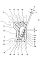
- the grease G passes through the sliding portion of the end face lip 52 by the centrifugal force as shown in FIG. There is concern about splashing toward the surrounding structure (the grease scattering direction is indicated by arrow A). If the scattered grease G adheres to the brake disc, it directly affects the brake performance. Therefore, the grease G should be avoided as much as possible.
- an object of the present invention is to provide a sealing device having a structure in which grease applied to the inner peripheral surface of the end face lip is less likely to scatter even when centrifugal force acts on the sealing device.
- the sealing device of the present invention is a sealing device that seals the foreign matter so that foreign matter outside the machine does not enter the machine, and has an end face lip that slidably contacts the end face portion of the rotating side part, and the end face
- the amount of grease applied to the inner peripheral surface of the tip end portion of the end face lip is larger than the amount of grease applied to the inner peripheral surface of the root portion of the end face lip.
- a small amount is set (claim 1).
- the amount of grease applied to the inner peripheral surface of the tip of the end face lip is set smaller than the amount of grease applied to the inner peripheral surface of the base of the end lip, the applied grease will come into contact with the end face of the rotating part.
- the contact width becomes smaller as compared with the conventional one, and thus is less susceptible to the influence of centrifugal force. Therefore, it is possible to suppress the grease from passing through the sliding portion of the end face lip and scattering.
- grease is applied to a part of the circumference of the inner peripheral surface of the end face lip, and on the premise of this, either the applied thickness of grease applied to the inner peripheral face of the end portion of the end face lip and the circumferential application width or Both are set to be smaller than the application thickness of grease applied to the inner peripheral surface of the root portion of the end face lip or the application width in the circumferential direction.
- the present invention is also effective to provide a grease trap on the outer peripheral side of the end surface lip in preparation for the case where the grease passes through the sliding portion of the end surface lip.
- the grease trap collects the grease, so that it is possible to suppress the grease from being scattered (claim 4).
- the sealing device of the present invention is suitable for use as a hub bearing seal for vehicles such as automobiles and other bearing seals having a configuration in which grease is applied to the inner peripheral surface of the end face lip in order to exert the effect of preventing grease scattering. (Claim 5).
- the grease application state is set to be different from the conventional one and a grease trap is provided, so that the grease applied to the inner peripheral surface of the end face lip is scattered even if centrifugal force acts on the sealing device. It is possible to provide a sealing device having a structure difficult to perform.
- Sectional drawing of the principal part of the sealing device which concerns on 1st Example of this invention (A) and (B) both principal part sectional drawing of the sealing device which concerns on the modification of 1st Example of this invention. Sectional drawing of the principal part of the sealing device which concerns on 2nd Example of this invention. Sectional drawing of the principal part of the sealing device which concerns on 3rd Example of this invention. Sectional drawing of the principal part of the sealing device which concerns on 4th Example of this invention. Sectional drawing of the principal part of the sealing device which concerns on a prior art example Sectional drawing of the principal part of the sealing device which concerns on another prior art example Cross-sectional view of the main part showing the state of grease scattering in the sealing device
- the present invention includes the following embodiments.
- (2) Grease application amount distribution (2-1) Grease application amount distribution applied to the side lip is as follows. That is, by setting the amount of grease applied from the vicinity of the lip base to the vicinity of the lip tip, the specification is such that the applied grease (except for the lip tip) does not contact the bearing inner ring during on-shaft. (2-2) With the above configuration, the grease is applied so that it does not contact the inner ring of the bearing while maintaining grease lubrication at the lip tip and maintaining muddy water resistance. It becomes.
- FIG. 1 shows a cross section of a main part of a sealing device 1 according to a first embodiment of the present invention.
- the sealing device 1 according to this embodiment is used as a hub bearing seal (hub seal) in a bearing portion of a vehicle wheel suspension device, and is configured as follows.
- a mounting ring 11 made of a rigid material such as a metal fixed to the inner peripheral surface of a housing 31 such as a bearing outer ring which is a stationary side mounting part in the bearing portion is provided, and a predetermined rubber is provided on the mounting ring 11.
- a rubber-like elastic body 21 made of a material is attached (crosslinked).
- the mounting ring 11 has a cylindrical portion 12 that is fitted to the inner peripheral surface of the housing 31, and a diameter of the cylindrical portion 12 via a bent portion 13 at one end (right side in the drawing) in the axial direction.
- a direction inward flange portion 14 is integrally formed.
- the rubber-like elastic body 21 is attached to the bent portion 13 and the flange portion 14 in the mounting ring 11, and the rubber-like elastic body 21 and the outer peripheral seal portion 22 that comes into stationary contact with the inner peripheral surface of the housing 31.
- An end surface lip (side lip) 23 that slidably contacts an end surface portion (axial end surface portion) 33 of a shaft 32 such as a bearing inner ring that is a rotating side component in the bearing portion, and an inner peripheral side of the end surface lip 23
- the second end lip (second side lip) 24 slidably contacts the end surface portion 33 of the shaft 32, and the outer end surface portion 34 of the shaft 32 slides inside the bearing (inside the machine) I of the second end surface lip 24.
- a radial lip (grease lip) 25 movably contacting is integrally formed.
- the end surface portion 33 includes a rounded portion having an arcuate cross section.
- the end face lip 23 and the second end face lip 24 are formed so as to gradually increase in diameter from the lip root parts 23a and 24a to the lip tip parts 23b and 24b, respectively.
- the lip tip portions 23b and 24b are slidably in contact with the end surface portion 33 of the shaft 32 so that foreign matter such as muddy water outside the bearing (outside the machine) O does not enter the machine I. So as to exert a sealing function.
- Grease G made of a fluid having viscosity is applied to the inner peripheral surfaces of the lips 23, 24, 25 in order to increase the mud water resistance of the lips 23, 24, 25 and to improve the sliding resistance. ing.
- a relatively small amount of the grease G applied to the inner peripheral surface of the end surface lip 23 is applied to the inner peripheral surface of the tip end portion 23b of the end surface lip 23 and a relatively large amount is applied to the inner peripheral surface of the root portion 23a of the end surface lip 23. More specifically, the grease G is applied over the entire inner peripheral surface of the end surface lip 23, and is applied to the inner peripheral surface of the tip end portion 23 b of the end surface lip 23.
- the applied thickness t 1 of the grease G is set smaller than the applied thickness t 2 of the grease G applied to the inner peripheral surface of the root portion 23a of the end face lip 23 (t 1 ⁇ t 2 ).
- the grease G is set so that the thickness of the grease G gradually increases from the lip tip 23b to the lip root 23a, and conversely, the grease G gradually decreases from the lip root 23a to the lip tip 23b. Is set to
- the grease G is applied in a relatively small amount on the inner peripheral surface of the tip end portion 23b of the end surface lip 23 and is applied in a relatively large amount on the inner peripheral surface of the root portion 23a of the end surface lip 23.
- the applied thickness t 1 of the grease G applied to the inner peripheral surface of the tip 23b of the end lip 23 is smaller than the applied thickness t 2 of the grease G applied to the inner peripheral surface of the root 23a of the end lip 23. Since the former is set, the contact width w 2 of the applied grease with respect to the end surface portion 33 of the shaft 32 corresponding to the applied thickness t 1 of the grease G applied to the inner peripheral surface of the lip tip portion 23b is: The contact width w 1 in the prior art shown in FIG.
- the amount of grease G applied to the inner peripheral surface of the lip tip 23b of the end lip 23 is smaller than the amount of grease G applied to the inner peripheral surface of the root 23a of the end lip 23.
- the grease G is applied over the entire inner peripheral surface of the end surface lip 23, and the inner periphery of the tip end portion 23b of the end surface lip 23 is applied.
- the application thickness t 1 of the grease G applied to the surface is set smaller than the application thickness t 2 of the grease G applied to the inner peripheral surface of the root portion 23 a of the end face lip 23 (t 1 ⁇ t 2 ). May be applied to a part of the circumference of the inner circumferential surface of the end lip 23. An example of this case will be described below.
- the grease G is applied to a plurality of locations on the inner peripheral surface of the end surface lip 23 and applied to the inner peripheral surface of the tip end portion 23b of the end surface lip 23.
- been circumferential coating width c 1 of the grease G is the root portion is smaller than the circumferential coating width c 2 of the grease G applied to the inner peripheral surface 23a (c 1 ⁇ c of the end face lip 23 2 ).
- the grease application thickness t is constant or substantially constant.
- grease G is applied to a plurality of locations on a part of the inner peripheral surface of the end surface lip 23 and applied to the inner peripheral surface of the tip end portion 23 b of the end surface lip 23.
- circumferential coating width c 1 of the grease G is the root portion is smaller than the circumferential coating width c 2 of the grease G applied to the inner peripheral surface 23a (c 1 ⁇ c of the end face lip 23 2 ).
- the application thickness t 1 of the grease G applied to the inner peripheral surface of the tip end portion 23 b of the end surface lip 23 is larger than the application thickness t 2 of the grease G applied to the inner peripheral surface of the root portion 23 a of the end surface lip 23. It is set small (t 1 ⁇ t 2 ).
- FIG. 3 shows a cross section of the main part of the sealing device 1 according to the second embodiment of the present invention.
- the sealing device 1 according to this embodiment is used as a hub bearing seal (hub seal) in a bearing portion of a vehicle wheel suspension device, and is configured as follows.
- a mounting ring 11 made of a rigid material such as a metal fixed to the inner peripheral surface of a housing 31 such as a bearing outer ring which is a stationary side mounting part in the bearing portion is provided, and a predetermined rubber is provided on the mounting ring 11.
- a rubber-like elastic body 21 made of a material is attached (crosslinked).
- the mounting ring 11 has a cylindrical portion 12 fitted to the inner peripheral surface of the housing 31, and a bent portion 15 and an inner peripheral cylinder are provided at one end (left side in the drawing) of the cylindrical portion 12 in the axial direction.
- a radially inward flange portion 14 is integrally formed through the portion 16, and a radially outward flange portion 17 is integrally formed at the other axial end (right side in the drawing) of the cylindrical portion 12. Molded.
- the rubber-like elastic body 21 is attached to the cylindrical portion 12, the bent portion 15, the inner peripheral cylindrical portion 16, and both flange portions 14, 17 in the mounting ring 11, and the end face of the housing 31 is formed by the rubber-like elastic body 21.
- An end face seal portion 26 that comes into stationary contact with the outer peripheral portion, an outer peripheral covering portion 27 that covers the outward flange portion 17 of the mounting ring 11, and an end face portion of a shaft 32 such as a bearing inner ring that is a rotation side component in the bearing portion.
- An end surface lip (side lip) 23 slidably contacting the (axial end surface portion) 33 and a second end surface lip slidably contacting the end surface portion 33 of the shaft 32 on the inner peripheral side of the end surface lip 23.
- the end surface portion 33 includes a rounded portion having an arcuate cross section.
- the end face lip 23 and the second end face lip 24 are formed so as to gradually increase in diameter from the lip root parts 23a and 24a to the lip tip parts 23b and 24b, respectively.
- the lip tip portions 23b and 24b are slidably in contact with the end surface portion 33 of the shaft 32 so that foreign matter such as muddy water outside the bearing (outside the machine) O does not enter the machine I. So as to exert a sealing function.
- Grease G made of a fluid having viscosity is applied to the inner peripheral surfaces of the lips 23, 24, and 25 in order to increase the mud water resistance of the lips 23, 24, and 25 and to improve the sliding resistance. Yes.
- a relatively small amount of the grease G applied to the inner peripheral surface of the end surface lip 23 is applied to the inner peripheral surface of the tip end portion 23b of the end surface lip 23 and a relatively large amount is applied to the inner peripheral surface of the root portion 23a of the end surface lip 23. More specifically, the grease G is applied over the entire inner peripheral surface of the end surface lip 23, and is applied to the inner peripheral surface of the tip end portion 23 b of the end surface lip 23.
- the applied thickness t 1 of the grease G is set smaller than the applied thickness t 2 of the grease G applied to the inner peripheral surface of the root portion 23a of the end face lip 23 (t 1 ⁇ t 2 ).
- the grease G is set so that the thickness of the grease G gradually increases from the lip tip 23b to the lip root 23a, and conversely, the grease G gradually decreases from the lip root 23a to the lip tip 23b. Is set to
- a grease trap 28 is provided on the outer peripheral side of the end face lip 23.
- the grease trap 28 has an annular shape and is formed into a lip shape, and its inner diameter is gradually reduced from the trap root portion 28a of the grease trap 28 to the trap tip portion 28b. Further, the grease trap 28 is formed integrally with the outer peripheral covering portion 27 by the rubber-like elastic body 21 and slidably contacts the end face portion 33 of the shaft 32 with the tip portion 28b. .
- the grease G is applied in a relatively small amount on the inner peripheral surface of the tip end portion 23b of the end surface lip 23 and is applied in a relatively large amount on the inner peripheral surface of the root portion 23a of the end surface lip 23.
- the applied thickness t 1 of the grease G applied to the inner peripheral surface of the tip 23b of the end lip 23 is smaller than the applied thickness t 2 of the grease G applied to the inner peripheral surface of the root 23a of the end lip 23. Since the former is set, the contact width w 2 of the applied grease with respect to the end surface portion 33 of the shaft 32 corresponding to the applied thickness t 1 of the grease G applied to the inner peripheral surface of the lip tip portion 23b is: The contact width w 1 in the prior art shown in FIG.
- the grease trap 28 is provided in advance on the outer peripheral side of the end face lip 23 in preparation for the case where the grease G passes through the sliding portion of the end face lip 23, the grease trap 28 may collect the grease G. It is possible. Therefore, it is possible to suppress the grease G from being scattered toward the outer peripheral side of the sealing device 1.
- the grease trap 28 has an annular shape and is shaped like a lip, and has an inner diameter that gradually decreases from the trap root portion 28a of the grease trap 28 to the trap tip portion 28b. Therefore, the collected grease G flows on the inner peripheral surface of the grease trap 28 from the trap tip portion 28b side to the trap root portion 28a side, and thus does not easily flow out of the trap tip portion 28b. Is expensive.
- the end surface lip 23 slidably contacts an end surface portion (axial end surface portion) 33 of a flange portion provided on a shaft 32 such as a bearing inner ring as a sliding counterpart.
- the sliding counterpart may be a part other than the flange portion provided on the shaft 32, for example, a metal ring attached to the outer peripheral surface of the shaft 32. An example of this case will be described below.
- FIG. 4 shows a cross section of the main part of the sealing device 1 according to the third embodiment of the present invention.
- the sealing device 1 according to this embodiment is used as a hub bearing seal (hub seal) in a bearing portion of an automobile wheel suspension device, and is combined with a metal ring 41 attached to the outer peripheral surface of a shaft 32.
- hub seal hub seal
- the metal ring 41 has a cylindrical portion 42 that is fitted to the outer peripheral surface of the shaft 32, and one end portion of the cylindrical portion 42 in the axial direction (on the bearing outside (outside of the machine) O side, right side in the drawing). A radially outward flange portion 44 is integrally formed.
- This metal ring 41 is also referred to as a slinger.
- a rubber-like elastic body 21 is attached (crosslinked).
- the mounting ring 11 has a cylindrical portion 12 that is fitted to the inner peripheral surface of the housing 31, and the other end in the axial direction of the cylindrical portion 12 (inside the bearing (inside the machine) I side, left in the drawing). Further, a radially inward flange portion 14 is formed integrally with the bent portion 13.
- the rubber-like elastic body 21 is attached to the cylindrical portion 12, the bent portion 13, and the flange portion 14 in the mounting ring 11, and makes a stationary contact with the inner peripheral surface of the housing 31 by the rubber-like elastic body 21.
- the radial lip 29 slidably contacts the outer peripheral surface portion 43 of the cylindrical portion 42 in the metal ring 41, and is slidable on the outer peripheral surface portion 43 of the cylindrical portion 42 in the metal ring 41 on the inner side of the radial lip 29.
- a radial lip (grease lip) 25 that comes into contact with is integrally formed.
- the end surface lip 23 is formed so as to gradually increase in diameter from the lip root portion 23a to the lip tip portion 23b, and the lip tip portion 23b is provided toward the outer peripheral side. Sealing to prevent foreign matter such as muddy water outside the bearing (outside the machine) O from entering the machine interior I by slidably contacting the end face part (machine inner end face part) 45 of the flange 44 in the metal ring 41 Demonstrate the function.
- Grease G made of a fluid having viscosity is applied to the inner peripheral surfaces of the lips 23, 25, 29 in order to increase the mud water resistance of the lips 23, 25, 29 and the sliding resistance. ing.
- a relatively small amount of the grease G applied to the inner peripheral surface of the end surface lip 23 is applied to the inner peripheral surface of the tip end portion 23b of the end surface lip 23 and a relatively large amount is applied to the inner peripheral surface of the root portion 23a of the end surface lip 23. More specifically, the grease G is applied over the entire inner peripheral surface of the end surface lip 23, and is applied to the inner peripheral surface of the tip end portion 23 b of the end surface lip 23.
- the applied thickness t 1 of the grease G is set smaller than the applied thickness t 2 of the grease G applied to the inner peripheral surface of the root portion 23a of the end face lip 23 (t 1 ⁇ t 2 ).
- the grease G is set so that the thickness of the grease G gradually increases from the lip tip 23b to the lip root 23a, and conversely, the grease G gradually decreases from the lip root 23a to the lip tip 23b. Is set to
- the grease G is applied in a relatively small amount on the inner peripheral surface of the tip end portion 23b of the end surface lip 23 and is applied in a relatively large amount on the inner peripheral surface of the root portion 23a of the end surface lip 23.
- the applied thickness t 1 of the grease G applied to the inner peripheral surface of the tip 23b of the end lip 23 is smaller than the applied thickness t 2 of the grease G applied to the inner peripheral surface of the root 23a of the end lip 23. Since the former is set, the contact width w 2 of the applied grease with respect to the end surface portion 33 of the shaft 32 corresponding to the applied thickness t 1 of the grease G applied to the inner peripheral surface of the lip tip portion 23b is: The contact width w 1 in the prior art shown in FIG.
- the grease G may be applied to a part of the circumference of the inner peripheral surface of the end face lip 23.
- the metal ring 41 may be a metal ring 41 with a magnetic encoder 47.
- the magnetic encoder 47 is formed in a ring shape by a predetermined rubber-like elastic material mixed with magnetic powder, and has a number of N poles and S poles alternately arranged at a predetermined pitch on the circumference as a circumferential magnetization pattern. In combination with a magnetic sensor (not shown), the rotational speed or rotational angle of the axle is sensed.
- such a magnetic encoder 47 is attached to the machine end face part 46 of the flange part 44 in the metal ring 41 (cross-linking adhesion), and the end face lip to the machine end face part 45 of the flange part 44 is provided. It is set as the structure which 23 contacts slidably.
- the sealing device 1 is a sealing device 1 that seals foreign matter so that foreign matter outside the machine O does not enter the inside I, and is a rotating side part (shaft) 32.
- a sealing device that has end face lips 23 and 24 that are slidably in contact with the end face portion 33, and applies lubricating grease G to the inner peripheral surfaces of the end face lips 23 and 24.
- (A) The amount of grease G applied to the inner peripheral surfaces of the end portions 23b, 24b of the end surface lips 23, 24 is the amount of grease G applied to the inner peripheral surfaces of the root portions 23a, 24a of the end surface lips 23, 24.
- the grease trap 28 is provided on the outer peripheral side of the end face lips 23, 24.
- the configuration of (B) alone is the only way to disperse the grease G. A suppression effect can be exhibited. Therefore, the content of the invention in this case is specified by the following configuration.
- (B-1) A sealing device that seals the foreign matter so that foreign matter does not enter the machine.
- the sealing device has an end face lip that slidably contacts the end face portion of the rotating part, and lubricates the inner peripheral surface of the end face lip.
- a sealing apparatus for applying grease for use wherein a grease trap is provided on the outer peripheral side of the end face lip.
- the grease trap In the sealing device according to (B-1), the grease trap has a lip shape, and an inner diameter thereof is gradually reduced from a root portion to a tip portion of the grease trap. Sealing device.
- (B-3) The sealing device according to (B-1) or (B-2), wherein the sealing device is used as a hub bearing seal or other bearing seal for a vehicle such as an automobile.
Abstract
Description
本発明の密封装置は、機外の異物が機内に侵入しないように前記異物をシールする密封装置であって、回転側部品の端面部に摺動可能に接触する端面リップを有し、前記端面リップの内周面に潤滑用グリースを塗布する密封装置において、前記端面リップの先端部内周面に塗布するグリースの塗布量を、前記端面リップの根元部内周面に塗布するグリースの塗布量よりも少量に設定したことを特徴とする(請求項1)。 In order to achieve the above object, the present invention employs the following means.
The sealing device of the present invention is a sealing device that seals the foreign matter so that foreign matter outside the machine does not enter the machine, and has an end face lip that slidably contacts the end face portion of the rotating side part, and the end face In the sealing device for applying the lubricating grease to the inner peripheral surface of the lip, the amount of grease applied to the inner peripheral surface of the tip end portion of the end face lip is larger than the amount of grease applied to the inner peripheral surface of the root portion of the end face lip. A small amount is set (claim 1).
(1)周辺構造へのグリース飛散を発生させないために、下記仕様のハブシールを提案する。
(2)グリースの塗布量分布
(2-1)サイドリップに塗布するグリースの塗布量分布を以下の仕様とする。すなわち、リップ根元付近よりリップ先端付近に向かってグリース塗布量を比較的少量に設定することにより、オンシャフト時に塗布グリース(リップ先端部を除く)がベアリング内輪に接触しない仕様とする。
(2-2)上記構成により、リップ先端部のグリース潤滑を保持し耐泥水性を維持しながら、ベアリング内輪に接触しないグリース塗布形態とすることにより、グリースがシールの外周側に飛散しにくい仕様となる。 The present invention includes the following embodiments.
(1) To prevent grease from splashing around the surrounding structure, a hub seal with the following specifications is proposed.
(2) Grease application amount distribution (2-1) Grease application amount distribution applied to the side lip is as follows. That is, by setting the amount of grease applied from the vicinity of the lip base to the vicinity of the lip tip, the specification is such that the applied grease (except for the lip tip) does not contact the bearing inner ring during on-shaft.
(2-2) With the above configuration, the grease is applied so that it does not contact the inner ring of the bearing while maintaining grease lubrication at the lip tip and maintaining muddy water resistance. It becomes.
図1は、本発明の第1実施例に係る密封装置1の要部断面を示している。当該実施例に係る密封装置1は自動車用車輪懸架装置におけるベアリング部にハブベアリングシール(ハブシール)として用いられるものであって、以下のように構成されている。 First embodiment
FIG. 1 shows a cross section of a main part of a
上記したように本発明は、端面リップ23のリップ先端部23b内周面に塗布するグリースGの塗布量を、端面リップ23の根元部23a内周面に塗布するグリースGの塗布量よりも少量に設定したことを特徴とし、これを実現するため上記第1実施例では、端面リップ23の内周面の全周に亙ってグリースGを塗布するとともに、端面リップ23の先端部23b内周面に塗布したグリースGの塗布厚みt1を、端面リップ23の根元部23a内周面に塗布したグリースGの塗布厚みt2よりも小さく設定したが(t1<t2)が、グリースGはこれを端面リップ23内周面の円周上一部に塗布するようにしても良い。以下にこの場合の例を説明する。 Modification of the first embodiment
As described above, in the present invention, the amount of grease G applied to the inner peripheral surface of the
図3は、本発明の第2実施例に係る密封装置1の要部断面を示している。当該実施例に係る密封装置1は自動車用車輪懸架装置におけるベアリング部にハブベアリングシール(ハブシール)として用いられるものであって、以下のように構成されている。 Second embodiment ...
FIG. 3 shows a cross section of the main part of the
図4は、本発明の第3実施例に係る密封装置1の要部断面を示している。当該実施例に係る密封装置1は自動車用車輪懸架装置におけるベアリング部にハブベアリングシール(ハブシール)として用いられるものであって、軸32の外周面に取り付けられる金属環41と組み合わされる。 Third embodiment
FIG. 4 shows a cross section of the main part of the
また、第4実施例として図5に示すように、金属環41は、磁気エンコーダ47付きの金属環41であっても良い。 Fourth embodiment
Further, as shown in FIG. 5 as the fourth embodiment, the
尚、上記第2実施例(図3)に係る密封装置1は、機外Oの異物が機内Iに侵入しないように前記異物をシールする密封装置1であって、回転側部品(軸)32の端面部33に摺動可能に接触する端面リップ23,24を有し、前記端面リップ23,24の内周面に潤滑用グリースGを塗布する密封装置において、
(A)前記端面リップ23,24の先端部23b,24b内周面に塗布するグリースGの塗布量を前記端面リップ23,24の根元部23a,24a内周面に塗布するグリースGの塗布量よりも少量に設定すること、および
(B)前記端面リップ23,24の外周側にグリーストラップ28を設けたこと
を特徴とするが、この(B)の構成はこれのみでも、グリースGの飛散抑制効果を発揮することができるものである。したがってこの場合の発明は、以下の構成をもってその内容が特定される。 Other configurations ...
The
(A) The amount of grease G applied to the inner peripheral surfaces of the
機外の異物が機内に侵入しないように前記異物をシールする密封装置であって、回転側部品の端面部に摺動可能に接触する端面リップを有し、前記端面リップの内周面に潤滑用グリースを塗布する密封装置において、前記端面リップの外周側に、グリーストラップを設けたことを特徴とする密封装置。
(B-2)
上記(B-1)記載の密封装置において、前記グリーストラップは、リップ状とされ、その内径寸法が前記グリーストラップの根元部から先端部へかけて徐々に縮小する形状とされていることを特徴とする密封装置。
(B-3)
上記(B-1)または(B-2)記載の密封装置において、当該密封装置は、自動車等車両用のハブベアリングシールまたはその他のベアリングシールとして用いられることを特徴とする密封装置。 (B-1)
A sealing device that seals the foreign matter so that foreign matter does not enter the machine. The sealing device has an end face lip that slidably contacts the end face portion of the rotating part, and lubricates the inner peripheral surface of the end face lip. A sealing apparatus for applying grease for use, wherein a grease trap is provided on the outer peripheral side of the end face lip.
(B-2)
In the sealing device according to (B-1), the grease trap has a lip shape, and an inner diameter thereof is gradually reduced from a root portion to a tip portion of the grease trap. Sealing device.
(B-3)
The sealing device according to (B-1) or (B-2), wherein the sealing device is used as a hub bearing seal or other bearing seal for a vehicle such as an automobile.
11 取付環
12,42 筒状部
13,15 屈曲部
14,17,44 フランジ部
16 内周筒部
21 ゴム状弾性体
22 外周シール部
23 端面リップ
23a,24a リップ根元部
23b,24b リップ先端部
24 第2端面リップ
25 ラジアルリップ
26 端面シール部
27 外周被覆部
28 グリーストラップ
28a トラップ根元部
28b トラップ先端部
31 ハウジング
32 軸
33,45,46 端面部
34,43 外周面部
41 金属環
47 磁気エンコーダ
G グリース
I 機内
O 機外 DESCRIPTION OF
Claims (5)
- 機外の異物が機内に侵入しないように前記異物をシールする密封装置であって、回転側部品の端面部に摺動可能に接触する端面リップを有し、前記端面リップの内周面に潤滑用グリースを塗布する密封装置において、
前記端面リップの先端部内周面に塗布するグリースの塗布量を、前記端面リップの根元部内周面に塗布するグリースの塗布量よりも少量に設定したことを特徴とする密封装置。 A sealing device that seals the foreign matter so that foreign matter does not enter the machine. The sealing device has an end face lip that slidably contacts the end face portion of the rotating part, and lubricates the inner peripheral surface of the end face lip. In a sealing device that applies grease for
The sealing device according to claim 1, wherein the amount of grease applied to the inner peripheral surface of the tip end portion of the end surface lip is set to be smaller than the amount of grease applied to the inner peripheral surface of the root portion of the end surface lip. - 請求項1記載の密封装置において、
前記端面リップの内周面の全周に亙って前記グリースを塗布し、
前記端面リップの先端部内周面に塗布するグリースの塗布厚みを、前記端面リップの根元部内周面に塗布するグリースの塗布厚みよりも小さく設定したことを特徴とする密封装置。 The sealing device according to claim 1.
Applying the grease over the entire circumference of the inner peripheral surface of the end face lip,
2. A sealing device according to claim 1, wherein a coating thickness of grease applied to the inner peripheral surface of the tip end portion of the end surface lip is set smaller than a coating thickness of grease applied to the inner peripheral surface of the root portion of the end surface lip. - 請求項1記載の密封装置において、
前記端面リップの内周面の円周上一部にグリースを塗布し、
前記端面リップの先端部内周面に塗布するグリースの塗布厚みおよび円周方向塗布幅の何れか一方または双方を、前記端面リップの根元部内周面に塗布するグリースの塗布厚み又は円周方向塗布幅よりも小さく設定したことを特徴とする密封装置。 The sealing device according to claim 1.
Apply grease to a part of the circumference of the inner peripheral surface of the end face lip,
Either or both of the application thickness and the circumferential application width of the grease applied to the inner peripheral surface of the tip end portion of the end face lip, the applied thickness or the peripheral application width of the grease applied to the inner peripheral surface of the root portion of the end face lip. A sealing device characterized by being set smaller than the above. - 請求項1乃至3の何れかに記載の密封装置において、
前記端面リップの外周側に、グリーストラップを設けたことを特徴とする密封装置。 The sealing device according to any one of claims 1 to 3,
A sealing device, wherein a grease trap is provided on an outer peripheral side of the end face lip. - 請求項1乃至4の何れかに記載の密封装置において、
当該密封装置は、自動車等車両用のハブベアリングシールまたはその他のベアリングシールとして用いられることを特徴とする密封装置。 The sealing device according to any one of claims 1 to 4,
The sealing device is used as a hub bearing seal or other bearing seal for a vehicle such as an automobile.
Priority Applications (5)
| Application Number | Priority Date | Filing Date | Title |
|---|---|---|---|
| KR1020177034872A KR20180011128A (en) | 2015-05-22 | 2016-05-18 | Sealing device |
| EP16799881.4A EP3299683A4 (en) | 2015-05-22 | 2016-05-18 | Sealing device |
| JP2017520641A JPWO2016190175A1 (en) | 2015-05-22 | 2016-05-18 | Sealing device |
| CN201680024284.5A CN107532722A (en) | 2015-05-22 | 2016-05-18 | Sealing device |
| US15/576,015 US20180156277A1 (en) | 2015-05-22 | 2016-05-18 | Sealing device |
Applications Claiming Priority (6)
| Application Number | Priority Date | Filing Date | Title |
|---|---|---|---|
| JP2015-104429 | 2015-05-22 | ||
| JP2015104428 | 2015-05-22 | ||
| JP2015104429 | 2015-05-22 | ||
| JP2015-104428 | 2015-05-22 | ||
| JP2015-172056 | 2015-09-01 | ||
| JP2015172056 | 2015-09-01 |
Publications (1)
| Publication Number | Publication Date |
|---|---|
| WO2016190175A1 true WO2016190175A1 (en) | 2016-12-01 |
Family
ID=57393191
Family Applications (1)
| Application Number | Title | Priority Date | Filing Date |
|---|---|---|---|
| PCT/JP2016/064674 WO2016190175A1 (en) | 2015-05-22 | 2016-05-18 | Sealing device |
Country Status (6)
| Country | Link |
|---|---|
| US (1) | US20180156277A1 (en) |
| EP (1) | EP3299683A4 (en) |
| JP (1) | JPWO2016190175A1 (en) |
| KR (1) | KR20180011128A (en) |
| CN (1) | CN107532722A (en) |
| WO (1) | WO2016190175A1 (en) |
Cited By (1)
| Publication number | Priority date | Publication date | Assignee | Title |
|---|---|---|---|---|
| JP2020008096A (en) * | 2018-07-09 | 2020-01-16 | Nok株式会社 | Sealing device |
Families Citing this family (5)
| Publication number | Priority date | Publication date | Assignee | Title |
|---|---|---|---|---|
| CN112901663B (en) * | 2016-06-20 | 2023-07-25 | Nok株式会社 | Sealing device |
| WO2018096994A1 (en) * | 2016-11-25 | 2018-05-31 | Nok株式会社 | Sealing device and sealing structure |
| WO2020100651A1 (en) | 2018-11-12 | 2020-05-22 | Nok株式会社 | Sealing device and grease adherence method |
| JP7417973B2 (en) * | 2019-03-18 | 2024-01-19 | 内山工業株式会社 | bearing sealing device |
| JP2021017976A (en) * | 2019-07-17 | 2021-02-15 | 光洋シーリングテクノ株式会社 | Sealing device for hub unit |
Citations (3)
| Publication number | Priority date | Publication date | Assignee | Title |
|---|---|---|---|---|
| JP2010071323A (en) * | 2008-09-16 | 2010-04-02 | Nok Corp | Sealing device |
| JP2012154373A (en) * | 2011-01-24 | 2012-08-16 | Ntn Corp | Wheel bearing seal |
| WO2013118782A1 (en) * | 2012-02-07 | 2013-08-15 | Ntn株式会社 | Wheel bearing device |
Family Cites Families (3)
| Publication number | Priority date | Publication date | Assignee | Title |
|---|---|---|---|---|
| JP2007211792A (en) * | 2006-02-07 | 2007-08-23 | Ntn Corp | Wheel bearing |
| JP2008151174A (en) * | 2006-12-14 | 2008-07-03 | Uchiyama Mfg Corp | Sealing device |
| JP2010185490A (en) * | 2009-02-10 | 2010-08-26 | Uchiyama Manufacturing Corp | Bearing sealing device |
-
2016
- 2016-05-18 CN CN201680024284.5A patent/CN107532722A/en active Pending
- 2016-05-18 EP EP16799881.4A patent/EP3299683A4/en not_active Withdrawn
- 2016-05-18 JP JP2017520641A patent/JPWO2016190175A1/en active Pending
- 2016-05-18 KR KR1020177034872A patent/KR20180011128A/en unknown
- 2016-05-18 US US15/576,015 patent/US20180156277A1/en not_active Abandoned
- 2016-05-18 WO PCT/JP2016/064674 patent/WO2016190175A1/en active Application Filing
Patent Citations (3)
| Publication number | Priority date | Publication date | Assignee | Title |
|---|---|---|---|---|
| JP2010071323A (en) * | 2008-09-16 | 2010-04-02 | Nok Corp | Sealing device |
| JP2012154373A (en) * | 2011-01-24 | 2012-08-16 | Ntn Corp | Wheel bearing seal |
| WO2013118782A1 (en) * | 2012-02-07 | 2013-08-15 | Ntn株式会社 | Wheel bearing device |
Non-Patent Citations (1)
| Title |
|---|
| See also references of EP3299683A4 * |
Cited By (2)
| Publication number | Priority date | Publication date | Assignee | Title |
|---|---|---|---|---|
| JP2020008096A (en) * | 2018-07-09 | 2020-01-16 | Nok株式会社 | Sealing device |
| JP7118781B2 (en) | 2018-07-09 | 2022-08-16 | Nok株式会社 | sealing device |
Also Published As
| Publication number | Publication date |
|---|---|
| EP3299683A4 (en) | 2018-05-30 |
| JPWO2016190175A1 (en) | 2018-02-15 |
| EP3299683A1 (en) | 2018-03-28 |
| US20180156277A1 (en) | 2018-06-07 |
| KR20180011128A (en) | 2018-01-31 |
| CN107532722A (en) | 2018-01-02 |
Similar Documents
| Publication | Publication Date | Title |
|---|---|---|
| WO2016190175A1 (en) | Sealing device | |
| WO2017038751A1 (en) | Sealing device | |
| JP6876610B2 (en) | Sealing device | |
| CN111465788B (en) | Sealing device | |
| US8523447B2 (en) | Wheel bearing arrangement having gasket | |
| JP2014240676A (en) | Wheel supporting bearing unit with seal | |
| JP2017124695A (en) | Vehicular bearing device | |
| JP2017026118A (en) | Wheel support rolling bearing unit, manufacturing method thereof and seal ring | |
| JP5896115B2 (en) | Sealing device | |
| JP2009222183A (en) | Seal structure | |
| JP2008014384A (en) | Sealing device | |
| JP5447788B2 (en) | Steering dust seal | |
| CN110088492B (en) | Sealing device | |
| KR101573401B1 (en) | Seal assembly and Wheel bearing using the same for vehicle | |
| JP2010002009A (en) | Rolling device | |
| KR101595560B1 (en) | Encoder seal assembly and Wheel bearing using the same for vehicle | |
| WO2015194414A1 (en) | Sealing device | |
| JP2008025628A (en) | Sealing device | |
| WO2015186677A1 (en) | Sealing device | |
| JP2012229742A (en) | Sealing device | |
| JP2006083981A (en) | Sealing device | |
| WO2022244839A1 (en) | Sealing device | |
| JP2018119598A (en) | Bearing sealing device | |
| JP7023681B2 (en) | Sealing device for hub unit | |
| WO2020013020A1 (en) | Sealing device |
Legal Events
| Date | Code | Title | Description |
|---|---|---|---|
| 121 | Ep: the epo has been informed by wipo that ep was designated in this application |
Ref document number: 16799881 Country of ref document: EP Kind code of ref document: A1 |
|
| ENP | Entry into the national phase |
Ref document number: 2017520641 Country of ref document: JP Kind code of ref document: A |
|
| WWE | Wipo information: entry into national phase |
Ref document number: 15576015 Country of ref document: US |
|
| NENP | Non-entry into the national phase |
Ref country code: DE |
|
| ENP | Entry into the national phase |
Ref document number: 20177034872 Country of ref document: KR Kind code of ref document: A |
|
| WWE | Wipo information: entry into national phase |
Ref document number: 2016799881 Country of ref document: EP |