JP5896115B2 - Sealing device - Google Patents
Sealing device Download PDFInfo
- Publication number
- JP5896115B2 JP5896115B2 JP2011257406A JP2011257406A JP5896115B2 JP 5896115 B2 JP5896115 B2 JP 5896115B2 JP 2011257406 A JP2011257406 A JP 2011257406A JP 2011257406 A JP2011257406 A JP 2011257406A JP 5896115 B2 JP5896115 B2 JP 5896115B2
- Authority
- JP
- Japan
- Prior art keywords
- metal ring
- outer peripheral
- oil seal
- dust cover
- muddy water
- Prior art date
- Legal status (The legal status is an assumption and is not a legal conclusion. Google has not performed a legal analysis and makes no representation as to the accuracy of the status listed.)
- Active
Links
- 238000007789 sealing Methods 0.000 title description 17
- 229910052751 metal Inorganic materials 0.000 claims description 56
- 239000002184 metal Substances 0.000 claims description 56
- 230000002093 peripheral effect Effects 0.000 claims description 54
- XLYOFNOQVPJJNP-UHFFFAOYSA-N water Substances O XLYOFNOQVPJJNP-UHFFFAOYSA-N 0.000 claims description 36
- 239000000428 dust Substances 0.000 claims description 30
- 239000000463 material Substances 0.000 claims description 10
- 239000002783 friction material Substances 0.000 claims description 6
- 239000007787 solid Substances 0.000 claims description 5
- 239000000314 lubricant Substances 0.000 claims 1
- 230000001050 lubricating effect Effects 0.000 description 4
- 229910000831 Steel Inorganic materials 0.000 description 2
- 230000000694 effects Effects 0.000 description 2
- JEIPFZHSYJVQDO-UHFFFAOYSA-N iron(III) oxide Inorganic materials O=[Fe]O[Fe]=O JEIPFZHSYJVQDO-UHFFFAOYSA-N 0.000 description 2
- 229920001343 polytetrafluoroethylene Polymers 0.000 description 2
- 239000004810 polytetrafluoroethylene Substances 0.000 description 2
- 239000010959 steel Substances 0.000 description 2
- OKTJSMMVPCPJKN-UHFFFAOYSA-N Carbon Chemical compound [C] OKTJSMMVPCPJKN-UHFFFAOYSA-N 0.000 description 1
- 241000287463 Phalacrocorax Species 0.000 description 1
- XAGFODPZIPBFFR-UHFFFAOYSA-N aluminium Chemical compound [Al] XAGFODPZIPBFFR-UHFFFAOYSA-N 0.000 description 1
- 238000005452 bending Methods 0.000 description 1
- 230000005540 biological transmission Effects 0.000 description 1
- 229910052799 carbon Inorganic materials 0.000 description 1
- 239000011248 coating agent Substances 0.000 description 1
- 238000000576 coating method Methods 0.000 description 1
- 230000007423 decrease Effects 0.000 description 1
- 238000000465 moulding Methods 0.000 description 1
- -1 polytetrafluoroethylene Polymers 0.000 description 1
- 230000002265 prevention Effects 0.000 description 1
- 238000004080 punching Methods 0.000 description 1
Images


Classifications
-
- F—MECHANICAL ENGINEERING; LIGHTING; HEATING; WEAPONS; BLASTING
- F16—ENGINEERING ELEMENTS AND UNITS; GENERAL MEASURES FOR PRODUCING AND MAINTAINING EFFECTIVE FUNCTIONING OF MACHINES OR INSTALLATIONS; THERMAL INSULATION IN GENERAL
- F16J—PISTONS; CYLINDERS; SEALINGS
- F16J15/00—Sealings
- F16J15/16—Sealings between relatively-moving surfaces
- F16J15/32—Sealings between relatively-moving surfaces with elastic sealings, e.g. O-rings
- F16J15/3248—Sealings between relatively-moving surfaces with elastic sealings, e.g. O-rings provided with casings or supports
- F16J15/3252—Sealings between relatively-moving surfaces with elastic sealings, e.g. O-rings provided with casings or supports with rigid casings or supports
- F16J15/3256—Sealings between relatively-moving surfaces with elastic sealings, e.g. O-rings provided with casings or supports with rigid casings or supports comprising two casing or support elements, one attached to each surface, e.g. cartridge or cassette seals
- F16J15/3264—Sealings between relatively-moving surfaces with elastic sealings, e.g. O-rings provided with casings or supports with rigid casings or supports comprising two casing or support elements, one attached to each surface, e.g. cartridge or cassette seals the elements being separable from each other
Description
本発明は、車両のトランスファー装置やトランスミッション、デファレンシャルギヤなど、機外からの泥水等に曝されやすい部分の軸周等を密封する密封装置であって、特に、回転側のダストカバーに密接させた対泥水シールリップによって、対油シールリップ側への泥水の浸入を防止する構造を備えるものに関する。 The present invention is a sealing device that seals a shaft periphery of a portion that is easily exposed to muddy water from outside the machine, such as a vehicle transfer device, a transmission, and a differential gear, and in particular, is in close contact with a dust cover on a rotating side. The present invention relates to a structure provided with a structure that prevents muddy water from entering the oil seal lip side by the muddy water seal lip.
機外からの泥水等に曝されやすい部分の軸周等を密封する密封装置として、従来から、図3に示すようなものが知られている。 2. Description of the Related Art Conventionally, as shown in FIG. 3 , a sealing device that seals a shaft periphery of a portion that is easily exposed to muddy water or the like from the outside of the machine is known.
図3において、参照符号2は車両のトランスファー装置等のハウジング、参照符号3は前記ハウジング2に挿通された回転軸である。密封装置100は、ハウジング2の内周に取り付けられた非回転のオイルシール110と、このオイルシール110の軸方向外側に位置して回転軸3の外周に取り付けられ、回転軸3と一体に回転される金属製のダストカバー120を備える。
In FIG. 3 ,
詳しくは、オイルシール110は、機内を向いて延びる対油シールリップ111と、この対油シールリップ111と反対側(外側)を向いて延びる対泥水シールリップ112を有する。対油シールリップ111は、回転軸3の外周面に摺動可能に密接されることによって機内油の漏洩を防止するものであり、対泥水シールリップ112は、ダストカバー120のフランジ部121に摺動可能に密接されることによって、機外Aから飛来する泥水等が、対油シールリップ111側へ浸入するのを抑制するものであり、ダストカバー120自体も、そのフランジ部121に生じる遠心力による振り切り作用を有し、更にその外径に形成された外筒部122をハウジング2の端部外周面に近接させることによって、泥水等の浸入に対する抑制効果の向上を図っている(例えば下記の特許文献参照)。
Specifically, the
この種の密封装置において、一層優れた耐泥水性能を求められる場合は、対泥水シールリップの枚数を増やすことが考えられるが、その場合、摺動トルクによるエネルギ損失が増大してしまうといった問題も指摘される。 In this type of sealing device, when more excellent muddy water resistance is required, it is conceivable to increase the number of muddy water sealing lips, but in that case, there is a problem that energy loss due to sliding torque increases. be pointed out.
本発明は、以上のような点に鑑みてなされたものであって、その技術的課題は、機内油の漏洩を防止すると共に機外からの泥水の浸入を防止する密封装置において、摺動トルクによるエネルギ損失の増大を抑制することにある。 The present invention has been made in view of the above points, and a technical problem thereof is a sliding torque in a sealing device that prevents leakage of oil in the machine and prevents intrusion of muddy water from the outside of the machine. The purpose is to suppress an increase in energy loss due to.
上述した技術的課題を有効に解決するための手段として、請求項1の発明に係る密封装置は、第一の金属環に対油シールリップが一体に成形されると共に前記第一の金属環に機外側に面して第二の金属環が密接嵌合され静止側に取り付けられるオイルシールと、このオイルシールの機外側に位置して回転側に取り付けられるダストカバーと、前記ダストカバーに一体に成形されると共に前記第二の金属環のフランジ部に摺動可能に密接される内周側の対泥水シールリップと、前記ダストカバーに一体に成形されると共に前記第二の金属環の外周筒部の内周面に摺動可能に密接される外周側の対泥水シールリップと、を備え、前記ダストカバーに形成された外周筒部が前記オイルシールの第一の金属環に形成された外周筒部の外周側を包囲するように延び、前記第二の金属環が低摩擦材からなり、前記低摩擦材が、前記第一の金属環と反対側の面に固体潤滑材料が設けられた金属板及び前記第一の金属環と反対側の面に鏡面が形成された金属板のいずれかから選択されたものであり、前記第二の金属環の外周筒部が前記第一の金属環の外周筒部の内周面に一体的に嵌着されたものである。
As a means for effectively solving the technical problem described above, the sealing device according to the invention of
本発明に係る密封装置によれば、複数の対泥水シールリップを設けても、摺動トルクによるエネルギ損失の増大を抑制することができる。 According to the sealing device according to the present invention, an increase in energy loss due to sliding torque can be suppressed even when a plurality of muddy water seal lips are provided .
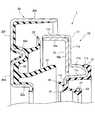
以下、本発明に係る密封装置の好ましい実施の形態について、図1及び図2を参照しながら説明する。 Hereinafter, a preferred embodiment of a sealing device according to the present invention will be described with reference to FIGS. 1 and 2 .
図2において、参照符号2は非回転のハウジング、参照符号3は前記ハウジング2に挿通され軸心の周りに回転可能な回転軸、参照符号1は本発明に係る密封装置で、ハウジング2の開口端部2aの内周面に取り付けられたオイルシール10と、回転軸3の外周面に前記オイルシール10の機外A側に位置して取り付けられたダストカバー20を備える。なお、ハウジング2は請求項1に記載された静止側、回転軸3は請求項1に記載された回転側に相当する。
In FIG. 2,
オイルシール10は、第一の金属環11にゴム材料で一体に成形された外周シール部12、対油シールリップ13、ダストリップ14及び泥水受け18と、前記第一の金属環11に機外A側に面して密接嵌合された第二の金属環15を備えるものである。
The
詳しくは、オイルシール10における第一の金属環11は、ハウジング2の開口端部2aの内周面に圧入嵌着される圧入筒部11aと、そこから機内B側へ向けて漸次小径になるように延びる外周シール保持部11bと、そこから機内Bと反対側へ向けて折り返された内周筒部11cと、この内周筒部11cの端部から内径側へ屈曲した内径フランジ部11dと、前記圧入筒部11aの機外A側の端部から外径側へ延びる外径フランジ部11eと、さらにその外径端部から図2の装着状態においてハウジング2と反対側へ屈曲して延びる外周筒部11fからなる。
Specifically, the
オイルシール10における外周シール部12は第一の金属環11の外周シール保持部11bの外周面に加硫接着されていて、ハウジング2の開口端部2aの内周面に圧入嵌着されるものであり、対油シールリップ13は、その根元が第一の金属環11の内径フランジ部11dに加硫接着されていて、機内B側へ延び、先端近傍の内径エッジ部13aが回転軸3の外周面に摺動可能に密接されるものであり、ダストリップ14は、その根元が対油シールリップ13の根元から分岐していて、この対油シールリップ13と反対側へ延び、先端が回転軸3の外周面に摺動可能に密接されるものであり、泥水受け18は、ダストリップ14の外周側に位置して、根元が第一の金属環11の内径フランジ部11dに加硫接着され、対油シールリップ13と反対側へ向けて漸次大径となる形状に突出したものである。対油シールリップ13にはその緊迫力及び径方向追随性を補償するガータスプリング17が装着されている。
The outer
第二の金属環15は第一の金属環11と反対側の面をPTFE(ポリテトラフルオロエチレン)やカーボンなどの固体潤滑材料をコーティングした金属板や鏡面加工した金属板などの低摩擦材で製作されたものであって、第一の金属環11の外周筒部11fの内周面に圧入嵌着により一体化された外周筒部15aと、この外周筒部15aから内径側へ延びて外径部が第一の金属環11の外径フランジ部11eと密接されたフランジ部15bからなる。
The
ダストカバー20は例えば金属板を打ち抜きプレス成形することにより製作されたものであって、回転軸3の外周面に圧入嵌着される内径筒部20aと、この内径筒部20aから外径方向へ円盤状に展開した内径フランジ部20dと、その外径部からオイルシール10における第二の金属環15の外周筒部15aの内周空間へ向けて凸形状となるように折り返された折り返し部20eと、この折り返し部20eから外径方向へ円盤状に展開した外径フランジ部20fと、更にその外径端部から図2の装着状態におけるハウジング2の開口端部2aの外周側へ向けて、オイルシール10における第一の金属環11の外周筒部11fの外周側を包囲するように延びる外周筒部20cからなる。
The
ダストカバー20には、オイルシール10側を向いた面にゴム材料からなる二段の対泥水シールリップ21,22が一体に成形されている。また、この対泥水シールリップ21,22の根元から延びるゴム層23が、前記ダストカバー20のオイルシール10側を向いた面のほぼ全面を覆うように加硫接着されている。
The
二段の対泥水シールリップ21,22のうち、内周側の対泥水シールリップ21は、その根元がゴム層23を介してダストカバー20の内径フランジ部20dに接着され、図1に示す未装着状態では、オイルシール10側へ向けて漸次大径になる円錐筒状をなしており、図2に示す装着状態では、適当に湾曲変形された状態でオイルシール10における第二の金属環15のフランジ部15bに摺動可能に密接されるものである。
Of the two-stage muddy
一方、外周側の対泥水シールリップ22は、その根元がゴム層23を介してダストカバー20の折り返し部20eの頂部付近に加硫接着され、根元から途中まではオイルシール10側へ向けて漸次大径になり、そこから外径側へ屈曲した形状に形成されている。そして図2に示す装着状態では、適当に湾曲されて先端が機外A側を向いた状態でオイルシール10における第二の金属環15の外周筒部15aの内周面に摺動可能に密接されるものである。
On the other hand, the base of the outer peripheral
また、図2に示す装着状態では、オイルシール10の第一及び第二の金属環11,15の外周筒部11f,15aは、ダストカバー20の外径フランジ部20fと近接対向しており、このため前記外周筒部11f,15aとダストカバー20の折り返し部20e、外径フランジ部20f及び外周筒部20cとの間には横向きの「J」字形に折れ曲がったラビリンス状の隙間Lが形成されている。
In the mounted state shown in FIG. 2 , the outer peripheral
以上のように構成された密封装置1において、オイルシール10は、第一の金属環11の圧入筒部11aを外周シール部12と共にハウジング2の開口端部2aの内周面に圧入し、前記第一の金属環11の外径フランジ部11eを前記開口端部2aの先端に当接させることによって、ハウジング2に位置決め固定する。また、ダストカバー20は、その内径筒部20aを回転軸3の外周面に圧入嵌着すると共に、内径フランジ部20d及び外径フランジ部20fを回転軸3のフランジ部に当接させることによって位置決め固定し、図示の装着状態とする。
In the
オイルシール10の対油シールリップ13は、回転軸3の外周面に摺動可能に密接されることによって、機内油が機外Aへ漏洩するのを防止するものである。
The
一方、対泥水シールリップ21,22の外周側には、ラビリンス状の隙間Lが形成されているので、機外Aから飛来する泥水等が対泥水シールリップ21,22による密封摺動部へ入りにくいものとなっており、ダストカバー20に設けられた対泥水シールリップ21,22は、回転軸3と一体に回転されるダストカバー20と共に回転しながら非回転のオイルシール10の第二の金属環15と密接摺動されることによって、機外Aからの泥水等の浸入を阻止するものであり、オイルシール10の泥水受け18は、対泥水シールリップ21,22の密封摺動部を万一通過した泥水を受け止め、泥水受け18による円周溝18aに沿って流下させるものである。泥水受け18に沿って流下した泥水は、回転する対泥水シールリップ21に滴下してその遠心力によって振り切られ、外周側へ押し戻される。ダストリップ14は、対泥水シールリップ21の内周側で、回転軸3の外周面に摺動可能に密接されることによって、対油シールリップ13側への泥水等の浸入を阻止するものである。
On the other hand, a labyrinth-shaped gap L is formed on the outer peripheral side of the
そして上記構成によれば、対泥水シールリップ21,22が摺接されるオイルシール10の第二の金属環15は、固体潤滑材料をコーティングした金属板など、低摩擦材又は鏡面材からなるものであるため、複数(図示の例では2段)の対泥水シールリップ21,22を設けたにも拘らず、摺動トルクによるエネルギ損失の増大が抑制される。
And according to the said structure, the
また、この形態では複数(図示の例では2段)の対泥水シールリップ21,22によって耐泥水性を確保しているため、これら対泥水シールリップ21,22には必ずしも耐泥水性に優れた材質は求められず、したがって対油シールリップ13と同材質(例えばACM)からなるものとすることができるが、耐泥水性に優れたNBRなどを用いても良いことはもちろんである。
Moreover, in this embodiment, since the mud water resistance is secured by a plurality (two stages in the illustrated example) of the mud
なお、オイルシール10の第二の金属環15は、上述のように金属板に固体潤滑材料をコーティングしたものである場合、摺動トルク低減のほか、防錆効果も奏するが、例えばSUS(ステンレス鋼)や、メッキ鋼板、アルミ系金属板などを用いることによって防錆を図ることもできる。
When the
1 密封装置
10 オイルシール
11 第一の金属環
12 外周シール部
13 対油シールリップ
14 ダストリップ
15 第二の金属環
20 ダストカバー
21,22 対泥水シールリップ
2 ハウジング(静止側)
3 回転軸(回転側)
A 機外
B 機内
DESCRIPTION OF
15 Second metal ring
20
3 Rotating shaft (Rotating side)
A Outside the machine B Inside the machine
Claims (1)
Priority Applications (3)
| Application Number | Priority Date | Filing Date | Title |
|---|---|---|---|
| JP2011257406A JP5896115B2 (en) | 2011-11-25 | 2011-11-25 | Sealing device |
| PCT/JP2012/059750 WO2013077010A1 (en) | 2011-11-25 | 2012-04-10 | Sealing device |
| CN201290000885.XU CN203847704U (en) | 2011-11-25 | 2012-04-10 | Sealing device |
Applications Claiming Priority (1)
| Application Number | Priority Date | Filing Date | Title |
|---|---|---|---|
| JP2011257406A JP5896115B2 (en) | 2011-11-25 | 2011-11-25 | Sealing device |
Related Child Applications (1)
| Application Number | Title | Priority Date | Filing Date |
|---|---|---|---|
| JP2015197539A Division JP6290843B2 (en) | 2015-10-05 | 2015-10-05 | Sealing device |
Publications (3)
| Publication Number | Publication Date |
|---|---|
| JP2013113319A JP2013113319A (en) | 2013-06-10 |
| JP2013113319A5 JP2013113319A5 (en) | 2014-07-24 |
| JP5896115B2 true JP5896115B2 (en) | 2016-03-30 |
Family
ID=48469472
Family Applications (1)
| Application Number | Title | Priority Date | Filing Date |
|---|---|---|---|
| JP2011257406A Active JP5896115B2 (en) | 2011-11-25 | 2011-11-25 | Sealing device |
Country Status (3)
| Country | Link |
|---|---|
| JP (1) | JP5896115B2 (en) |
| CN (1) | CN203847704U (en) |
| WO (1) | WO2013077010A1 (en) |
Families Citing this family (6)
| Publication number | Priority date | Publication date | Assignee | Title |
|---|---|---|---|---|
| EP2949972B1 (en) * | 2014-05-26 | 2017-03-15 | Carl Freudenberg KG | Cassette seal |
| WO2015186677A1 (en) * | 2014-06-03 | 2015-12-10 | Nok株式会社 | Sealing device |
| WO2016111129A1 (en) * | 2015-01-07 | 2016-07-14 | Nok株式会社 | Sealing structure using torsional damper and oil seal |
| WO2017038752A1 (en) * | 2015-09-03 | 2017-03-09 | Nok株式会社 | Sealing structure |
| KR102065154B1 (en) * | 2017-10-23 | 2020-02-11 | 현대위아 주식회사 | Power transfer unit having dust preventing structure |
| JP2022553514A (en) * | 2019-10-15 | 2022-12-23 | ボルボトラックコーポレーション | Wheel bearing sealing device and vehicle |
Family Cites Families (5)
| Publication number | Priority date | Publication date | Assignee | Title |
|---|---|---|---|---|
| JPH0512534Y2 (en) * | 1986-05-20 | 1993-03-31 | ||
| US5398942A (en) * | 1992-09-02 | 1995-03-21 | Dana Corporation | Annular lubricant seal assembly |
| JP2009162304A (en) * | 2008-01-07 | 2009-07-23 | Jtekt Corp | Bearing sealing device |
| JP5376211B2 (en) * | 2008-08-08 | 2013-12-25 | 株式会社ジェイテクト | Rolling bearing device |
| JP5311044B2 (en) * | 2009-08-21 | 2013-10-09 | Nok株式会社 | Sealing device |
-
2011
- 2011-11-25 JP JP2011257406A patent/JP5896115B2/en active Active
-
2012
- 2012-04-10 WO PCT/JP2012/059750 patent/WO2013077010A1/en active Application Filing
- 2012-04-10 CN CN201290000885.XU patent/CN203847704U/en not_active Expired - Lifetime
Also Published As
| Publication number | Publication date |
|---|---|
| CN203847704U (en) | 2014-09-24 |
| JP2013113319A (en) | 2013-06-10 |
| WO2013077010A1 (en) | 2013-05-30 |
Similar Documents
| Publication | Publication Date | Title |
|---|---|---|
| JP6196408B1 (en) | Sealing device | |
| JP5896115B2 (en) | Sealing device | |
| JP5218735B2 (en) | Sealing device | |
| JP5158389B2 (en) | Sealing device | |
| EP2881631B1 (en) | Sealing device | |
| JP2013130296A (en) | Sealing device | |
| JP6208665B2 (en) | Sealing device | |
| JPWO2009078314A1 (en) | Sealing device | |
| JP2013142474A (en) | Shaft seal | |
| JP5892312B2 (en) | Sealing device | |
| CN103238012B (en) | Seal arrangement and sealing configuration | |
| JP2012057729A (en) | Oil seal structure | |
| JP2009103209A (en) | Sealing device | |
| JP6378548B2 (en) | Sealing device | |
| JP2017026073A (en) | Sealing device | |
| JP6290843B2 (en) | Sealing device | |
| JP2008175301A (en) | Rolling bearing with sealing device | |
| JP2009097607A (en) | Oil seal | |
| JP6000833B2 (en) | Sealing device | |
| JP2011132980A (en) | Muddy water-proof oil seal | |
| JP3138507U (en) | Sealing device | |
| CN113167388A (en) | Crankshaft seal design | |
| JP6920034B2 (en) | Sealing device | |
| JP2016080017A (en) | Sealing device for wheel support bearing | |
| JP2013249875A (en) | Friction drive-type wave transmission |
Legal Events
| Date | Code | Title | Description |
|---|---|---|---|
| A521 | Request for written amendment filed |
Free format text: JAPANESE INTERMEDIATE CODE: A523 Effective date: 20140605 |
|
| A621 | Written request for application examination |
Free format text: JAPANESE INTERMEDIATE CODE: A621 Effective date: 20141006 |
|
| A131 | Notification of reasons for refusal |
Free format text: JAPANESE INTERMEDIATE CODE: A131 Effective date: 20150805 |
|
| A521 | Request for written amendment filed |
Free format text: JAPANESE INTERMEDIATE CODE: A523 Effective date: 20151005 |
|
| A131 | Notification of reasons for refusal |
Free format text: JAPANESE INTERMEDIATE CODE: A131 Effective date: 20151028 |
|
| A521 | Request for written amendment filed |
Free format text: JAPANESE INTERMEDIATE CODE: A523 Effective date: 20151225 |
|
| TRDD | Decision of grant or rejection written | ||
| A01 | Written decision to grant a patent or to grant a registration (utility model) |
Free format text: JAPANESE INTERMEDIATE CODE: A01 Effective date: 20160203 |
|
| A61 | First payment of annual fees (during grant procedure) |
Free format text: JAPANESE INTERMEDIATE CODE: A61 Effective date: 20160216 |
|
| R150 | Certificate of patent or registration of utility model |
Ref document number: 5896115 Country of ref document: JP Free format text: JAPANESE INTERMEDIATE CODE: R150 |
|
| R250 | Receipt of annual fees |
Free format text: JAPANESE INTERMEDIATE CODE: R250 |
|
| R250 | Receipt of annual fees |
Free format text: JAPANESE INTERMEDIATE CODE: R250 |
|
| R250 | Receipt of annual fees |
Free format text: JAPANESE INTERMEDIATE CODE: R250 |
|
| R250 | Receipt of annual fees |
Free format text: JAPANESE INTERMEDIATE CODE: R250 |