JP2009097607A - Oil seal - Google Patents
Oil seal Download PDFInfo
- Publication number
- JP2009097607A JP2009097607A JP2007269000A JP2007269000A JP2009097607A JP 2009097607 A JP2009097607 A JP 2009097607A JP 2007269000 A JP2007269000 A JP 2007269000A JP 2007269000 A JP2007269000 A JP 2007269000A JP 2009097607 A JP2009097607 A JP 2009097607A
- Authority
- JP
- Japan
- Prior art keywords
- seal lip
- dust
- peripheral surface
- outer peripheral
- muddy water
- Prior art date
- Legal status (The legal status is an assumption and is not a legal conclusion. Google has not performed a legal analysis and makes no representation as to the accuracy of the status listed.)
- Withdrawn
Links
- 239000000428 dust Substances 0.000 claims abstract description 46
- 230000002093 peripheral effect Effects 0.000 claims abstract description 34
- 239000000314 lubricant Substances 0.000 claims abstract description 8
- 230000001050 lubricating effect Effects 0.000 claims abstract description 7
- 230000000717 retained effect Effects 0.000 claims 1
- XLYOFNOQVPJJNP-UHFFFAOYSA-N water Substances O XLYOFNOQVPJJNP-UHFFFAOYSA-N 0.000 abstract description 19
- 238000007789 sealing Methods 0.000 abstract description 9
- 238000005299 abrasion Methods 0.000 abstract 1
- 239000002184 metal Substances 0.000 description 8
- 238000005461 lubrication Methods 0.000 description 5
- 239000004519 grease Substances 0.000 description 4
- 239000013013 elastic material Substances 0.000 description 2
- 239000000565 sealant Substances 0.000 description 2
- 229910000831 Steel Inorganic materials 0.000 description 1
- 239000003795 chemical substances by application Substances 0.000 description 1
- 230000006866 deterioration Effects 0.000 description 1
- 239000012530 fluid Substances 0.000 description 1
- 230000003014 reinforcing effect Effects 0.000 description 1
- 239000010959 steel Substances 0.000 description 1
Images

Landscapes
- Sealing With Elastic Sealing Lips (AREA)
Abstract
Description
本発明は、自動車や一般機械、産業機械等における回転体の外周を、シールリップによって密封するオイルシールに関する。 The present invention relates to an oil seal that seals the outer periphery of a rotating body in an automobile, a general machine, an industrial machine or the like with a seal lip.
回転体の外周をシールリップによって密封するオイルシール下記の特許文献に記載されたようなものが広く知られている。図3は、この種の従来のオイルシールを、その軸心Oを通る平面で切断して示す半断面図である。
図3に示されるオイルシール100は、ゴム状弾性材料で環状に成形されたものであって、不図示の軸孔ハウジングの内周面に密嵌される固定シール部101と、その内周側で前記軸孔ハウジングに挿通された回転軸200の外周面に摺動可能に密接される主シールリップ103及びダストシールリップ104が、中間径方向部102を介して互いに連続して形成されており、固定シール部101から中間径方向部102にかけて、補強用の金属環105が一体的に埋設されている。また、主シールリップ103の外周は円周方向に連続した溝状に形成され、主シールリップ103の永久変形に起因する緊迫力の低下を補償すると共に回転軸200に対する径方向追随性を確保するためのガータスプリング106が嵌着されている。
An
すなわちこのオイルシール100は、固定シール部101が、不図示の軸孔ハウジングの内周面に圧入嵌着され、主シールリップ103の先端内周部103aが、回転軸200の外周面に摺動可能に密接されることによって、この主シールリップ103が向いた機内A側の密封対象流体(油)が軸周から機外Bへ漏洩するのを阻止すると共に、ダストシールリップ104が、回転軸200の外周面に摺動可能に密接されることによって、このダストシールリップ104が向いた機外B側からのダストや泥水等の浸入を阻止するものである。
That is, in this
この種のオイルシール100において、耐ダスト性、耐泥水性は、一般的な使用条件では問題ないが、例えば自動車のパワーステアリングにおけるインプットシャフトなどの軸周を密封するオイルシールでは、耐ダスト性、耐泥水性の一層の向上が要求されている。そして耐ダスト性、耐泥水性の向上を図るには、ダストシールリップ104も主シールリップ103と同様にガータスプリングを取り付けて、回転軸200の外周面に対する緊迫力を増大させることによりダストや泥水等に対する密封性を向上させることが考えられる。
In this type of
しかし、この場合は緊迫力の増大によってダストシールリップ104の摺動部の摩耗が促進されてしまい、結局、主シールリップ103の摺動部へのダストや泥水等の介入による密封性の早期低下が懸念されるため、実用化されなかった。
However, in this case, the wear of the sliding portion of the
本発明は、以上のような点に鑑みてなされたものであって、その技術的課題とするところは、耐ダスト性、耐泥水性に優れたオイルシールを提供することにある。 This invention is made | formed in view of the above points, The place made into the technical subject is to provide the oil seal excellent in dust resistance and muddy water resistance.
上述した技術的課題を有効に解決するための手段として、本発明に係るオイルシールは、機内側へ延び、回転体の外周面に摺動可能に密接される主シールリップと、この主シールリップの根元から機外側へ延び、前記回転体の外周面に摺動可能に密接されるダストシールリップとを備え、前記ダストシールリップの外周面にガータスプリングが嵌着され、このダストシールリップにおける前記回転体との摺動面に円周方向へ連続した所要数の潤滑溝が形成され、この潤滑溝に潤滑剤が保持されたものである。 As means for effectively solving the technical problems described above, an oil seal according to the present invention extends to the inside of the machine and is slidably in close contact with the outer peripheral surface of the rotating body, and the main seal lip. A dust seal lip that extends outward from the base of the rotary body and is slidably in close contact with the outer peripheral surface of the rotating body, and a garter spring is fitted on the outer peripheral surface of the dust seal lip, A required number of lubrication grooves continuous in the circumferential direction are formed on the sliding surface of the first and second lubricants, and a lubricant is held in the lubrication grooves.
本発明に係るオイルシールによれば、ガータスプリングによって回転体に対するダストシールリップの緊迫力が増大してその摺動面の面圧が高まると共に、ダストシールリップと回転体との摺動部に介在する潤滑剤によって、ダストや泥水等に対する密封性が向上し、主シールリップの摺動部へのダストや泥水等の介入を有効に防止できる。しかも、前記潤滑剤によってダストシールリップの摺動部の摩耗が抑制されるので、ダストや泥水等に対する優れた密封性が長期間にわたって持続され、その結果、耐ダスト性、耐泥水性を著しく向上することができる。 According to the oil seal of the present invention, the garter spring increases the pressing force of the dust seal lip against the rotating body to increase the surface pressure of the sliding surface, and lubrication interposed in the sliding portion between the dust seal lip and the rotating body. The agent improves the sealing performance against dust, muddy water, etc., and can effectively prevent the intervention of dust, muddy water, etc. into the sliding part of the main seal lip. In addition, since the wear of the sliding portion of the dust seal lip is suppressed by the lubricant, excellent sealing performance against dust and muddy water is maintained for a long period of time, and as a result, dust resistance and mud water resistance are remarkably improved. be able to.
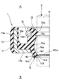
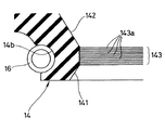
以下、本発明に係る密封装置を、図面を参照しながら詳細に説明する。まず図1は、本発明に係るオイルシールの好ましい実施の形態を、その軸心Oを通る平面で切断して示す半断面図、図2は、図1の要部を拡大して示す断面図である。 Hereinafter, a sealing device according to the present invention will be described in detail with reference to the drawings. First, FIG. 1 is a half sectional view showing a preferred embodiment of an oil seal according to the present invention by cutting along a plane passing through its axis O, and FIG. 2 is a sectional view showing an enlarged main part of FIG. It is.
このオイルシール1は、例えば自動車のパワーステアリングにおけるインプットシャフトなどの軸周を密封するものであって、金属環11に、耐熱性、耐寒性、耐油性及び耐摩耗性などを考慮して選択されたゴム状弾性材料で成形された固定シール部12、主シールリップ13及びダストシールリップ14が一体的に設けられ、主シールリップ13及びダストシールリップ14の外周面にガータスプリング15,16がそれぞれ嵌着されたものである。
The oil seal 1 seals the circumference of an input shaft or the like in a power steering of an automobile, for example, and is selected for the
金属環11は、SPCCなどの鋼板を打ち抜きプレス成形したものであって、円筒部11aと、その一端から内周側へ屈曲した内向きフランジ部11bからなる断面略L字形を呈する。
The
固定シール部12は、金属環11における円筒部11aの外周面を覆うように一体的に接着されており、不図示の軸孔ハウジングの内周面に、径方向に適当に圧縮された状態で密嵌固定されるものである。
The
主シールリップ13は、固定シール部12から金属環11の円筒部11aの内周面へ廻り込んだゴム層12aを介してこの固定シール部12と連続しており、金属環11の内向きフランジ部11bに一体的に接着された根元13aから、装着状態において機内A側となる方向へ延びている。主シールリップ13の先端近傍の内周面には、軸孔ハウジングの内周に挿通される回転軸2の外周面に適当な締め代をもって密接される断面山形の主エッジ13bと、それより機外B側に位置する副エッジ13cが形成されている。なお、回転軸2は例えば上述のパワーステアリングにおけるインプットシャフトであって、請求項1に記載された回転体に相当する。
The
ダストシールリップ14は、主シールリップ13の根元13aと連続して金属環11の内向きフランジ部11bに一体的に接着された根元14aから、主シールリップ13と反対側、すなわち装着状態において機外B側となる方向へ延びている。
The
ダストシールリップ14の先端近傍の内周面は、先端側へ向けて大径となる先端側円錐面141と、それより根元14a側で、根元14a側へ向けて大径となる根元側円錐面142と、両円錐面141,142の間にあって回転軸2の外周面に適当な締め代をもって密接される摺動面143からなり、この摺動面143には、図2に拡大して示されるように、互いに平行で円周方向へ連続した複数の潤滑溝143aが形成されている。また、前記摺動面143には、潤滑剤として不図示のグリースが塗布されており、このグリースは、潤滑溝143aによって回転軸2の外周面との間に保持されるようになっている。
The inner peripheral surface in the vicinity of the tip of the
ガータスプリング15,16は、金属製のコイルスプリングを環状に繋げたものであって、主シールリップ13及びダストシールリップ14の外周面に形成された環状溝13d,14bに嵌着されている。
The
以上のように構成されたオイルシール1は、主シールリップ13が機内A側を向くように固定シール部12が軸孔ハウジングの内周面に圧入嵌着され、主シールリップ13における主エッジ13bが、回転軸2の外周面に摺動可能に密接され、機内Aの内圧によっては副エッジ13cも回転軸2の外周面に摺動可能に密接されることによって、機内Aの密封対象油が軸周から機外B側へ漏洩するのを防止するものである。
In the oil seal 1 configured as described above, the
一方、ダストシールリップ14は、その摺動面143が回転軸2の外周面に摺動可能に密接されることによって、機外Bの大気中のダストや泥水が、主シールリップ13における主エッジ13b(及び副エッジ13c)と回転軸2の外周面との摺動部に介入するのを防止して主シールリップ13の摩耗を抑制するものである。そしてこのダストシールリップ14は、回転軸2の外周面に対する緊迫力、言い換えれば摺動面143の面圧が、ガータスプリング16によって大きなものとなっており、しかも前記摺動面143に形成された潤滑溝143aによって回転軸2の外周面との間に介在されたグリースが、ダストや泥水の通過を遮断する密封剤(シーラント)として機能するので、ダストや泥水に対する優れた密封性を発揮する。
On the other hand, the
また、潤滑溝143aによって保持されたグリースが、ダストシールリップ14の摺動面143と回転軸2の外周面との間に潤滑膜として介在するため、ダストシールリップ14の摺動抵抗が著しく低減されて、摩耗も著しく抑制される。このためダストや泥水等に対する優れた密封性が長期間にわたって持続され、その結果、主シールリップ13の摩耗も長期間にわたって抑制され、耐ダスト性、耐泥水性を著しく向上することができる。
Further, since the grease held by the
1 オイルシール
11 金属環
12 固定シール部
13 主シールリップ
14 ダストシールリップ
143 摺動面
143a 潤滑溝
15,16 ガータスプリング
2 回転軸(回転体)
A 機内
B 機外
DESCRIPTION OF SYMBOLS 1
A In-flight B Out-of-flight
Claims (1)
Priority Applications (1)
| Application Number | Priority Date | Filing Date | Title |
|---|---|---|---|
| JP2007269000A JP2009097607A (en) | 2007-10-16 | 2007-10-16 | Oil seal |
Applications Claiming Priority (1)
| Application Number | Priority Date | Filing Date | Title |
|---|---|---|---|
| JP2007269000A JP2009097607A (en) | 2007-10-16 | 2007-10-16 | Oil seal |
Publications (1)
| Publication Number | Publication Date |
|---|---|
| JP2009097607A true JP2009097607A (en) | 2009-05-07 |
Family
ID=40700799
Family Applications (1)
| Application Number | Title | Priority Date | Filing Date |
|---|---|---|---|
| JP2007269000A Withdrawn JP2009097607A (en) | 2007-10-16 | 2007-10-16 | Oil seal |
Country Status (1)
| Country | Link |
|---|---|
| JP (1) | JP2009097607A (en) |
Cited By (4)
| Publication number | Priority date | Publication date | Assignee | Title |
|---|---|---|---|---|
| CN104358880A (en) * | 2014-11-18 | 2015-02-18 | 烟台润蚨祥油封有限公司 | Rotary motion oil seal |
| CN109357016A (en) * | 2018-09-28 | 2019-02-19 | 重庆春阳密封制品有限公司 | Dust-proof and oil-proof combined oil seal |
| CN111980909A (en) * | 2020-07-21 | 2020-11-24 | 镇江联创机械配件有限公司 | Rod sealing element of piston pump |
| CN116324235A (en) * | 2020-10-28 | 2023-06-23 | 纳博特斯克有限公司 | Vacuum seal and drive transmission |
-
2007
- 2007-10-16 JP JP2007269000A patent/JP2009097607A/en not_active Withdrawn
Cited By (4)
| Publication number | Priority date | Publication date | Assignee | Title |
|---|---|---|---|---|
| CN104358880A (en) * | 2014-11-18 | 2015-02-18 | 烟台润蚨祥油封有限公司 | Rotary motion oil seal |
| CN109357016A (en) * | 2018-09-28 | 2019-02-19 | 重庆春阳密封制品有限公司 | Dust-proof and oil-proof combined oil seal |
| CN111980909A (en) * | 2020-07-21 | 2020-11-24 | 镇江联创机械配件有限公司 | Rod sealing element of piston pump |
| CN116324235A (en) * | 2020-10-28 | 2023-06-23 | 纳博特斯克有限公司 | Vacuum seal and drive transmission |
Similar Documents
| Publication | Publication Date | Title |
|---|---|---|
| JP5218735B2 (en) | Sealing device | |
| US10520036B2 (en) | Sealing device | |
| JP6043304B2 (en) | Low torque radial shaft seal assembly | |
| WO2014021179A1 (en) | Sealing device | |
| JP2010025138A (en) | Sealing arrangement | |
| JP5892312B2 (en) | Sealing device | |
| JP5820741B2 (en) | Engine transmission case sealing device | |
| JP5896115B2 (en) | Sealing device | |
| WO2021182057A1 (en) | Sealing device and reduction gear | |
| JP2011174570A (en) | Sealing device | |
| JP2005147356A (en) | Sealing device | |
| KR20140137408A (en) | Radial shaft seal with static and hydrodynamic sealing features | |
| JP6405389B2 (en) | Sealing device | |
| JP5311044B2 (en) | Sealing device | |
| JP6378548B2 (en) | Sealing device | |
| CN113167386B (en) | Sealing device | |
| CN212251132U (en) | Sealing device | |
| JP2015230098A (en) | Assembly with rotation shaft seal ring including seal extremity end curved into sinewave shape and the rotation shaft seal ring | |
| WO2017094599A1 (en) | Seal device | |
| JP6000833B2 (en) | Sealing device | |
| JP2005240932A (en) | Sealing device | |
| JP3138507U (en) | Sealing device | |
| JP2010060120A (en) | Sealing device | |
| WO2017099009A1 (en) | Sealing device | |
| JP2011058585A (en) | Sealing device |
Legal Events
| Date | Code | Title | Description |
|---|---|---|---|
| A300 | Withdrawal of application because of no request for examination |
Free format text: JAPANESE INTERMEDIATE CODE: A300 Effective date: 20110104 |