WO2016189702A1 - 太陽熱収集装置、集熱管の予熱方法および熱媒導入方法 - Google Patents
太陽熱収集装置、集熱管の予熱方法および熱媒導入方法 Download PDFInfo
- Publication number
- WO2016189702A1 WO2016189702A1 PCT/JP2015/065271 JP2015065271W WO2016189702A1 WO 2016189702 A1 WO2016189702 A1 WO 2016189702A1 JP 2015065271 W JP2015065271 W JP 2015065271W WO 2016189702 A1 WO2016189702 A1 WO 2016189702A1
- Authority
- WO
- WIPO (PCT)
- Prior art keywords
- heat collecting
- collecting tube
- heat
- light shielding
- shielding member
- Prior art date
- Legal status (The legal status is an assumption and is not a legal conclusion. Google has not performed a legal analysis and makes no representation as to the accuracy of the status listed.)
- Ceased
Links
Images




Classifications
-
- F—MECHANICAL ENGINEERING; LIGHTING; HEATING; WEAPONS; BLASTING
- F24—HEATING; RANGES; VENTILATING
- F24S—SOLAR HEAT COLLECTORS; SOLAR HEAT SYSTEMS
- F24S80/00—Details, accessories or component parts of solar heat collectors not provided for in groups F24S10/00-F24S70/00
-
- F—MECHANICAL ENGINEERING; LIGHTING; HEATING; WEAPONS; BLASTING
- F24—HEATING; RANGES; VENTILATING
- F24S—SOLAR HEAT COLLECTORS; SOLAR HEAT SYSTEMS
- F24S10/00—Solar heat collectors using working fluids
- F24S10/70—Solar heat collectors using working fluids the working fluids being conveyed through tubular absorbing conduits
-
- Y—GENERAL TAGGING OF NEW TECHNOLOGICAL DEVELOPMENTS; GENERAL TAGGING OF CROSS-SECTIONAL TECHNOLOGIES SPANNING OVER SEVERAL SECTIONS OF THE IPC; TECHNICAL SUBJECTS COVERED BY FORMER USPC CROSS-REFERENCE ART COLLECTIONS [XRACs] AND DIGESTS
- Y02—TECHNOLOGIES OR APPLICATIONS FOR MITIGATION OR ADAPTATION AGAINST CLIMATE CHANGE
- Y02E—REDUCTION OF GREENHOUSE GAS [GHG] EMISSIONS, RELATED TO ENERGY GENERATION, TRANSMISSION OR DISTRIBUTION
- Y02E10/00—Energy generation through renewable energy sources
- Y02E10/40—Solar thermal energy, e.g. solar towers
- Y02E10/44—Heat exchange systems
Definitions
- the present invention relates to a solar heat collecting apparatus that heats a heat medium flowing in a heat collecting tube by collecting sunlight.
- Solar heat that generates electricity by concentrating sunlight on the heat collection tube using a reflector, heating the heat medium flowing in the heat collection tube, generating steam using the heated heat medium, and turning the steam turbine Power generation systems are known.
- the solar thermal power generation system has a lower introduction cost than the solar power generation system and can generate power for 24 hours by heat storage.
- a solar thermal power generation system using oil as a heat medium has been proposed (see, for example, Patent Document 1).
- molten salt has attracted attention as a heat medium used in solar thermal power generation systems. Since the molten salt has a high boiling point, the operating temperature can be made relatively high according to the molten salt, and power generation efficiency is improved by generating high-temperature steam.
- the molten salt solidifies at about 250 ° C, when the molten salt is poured into the heat collection tube after startup and maintenance, if the temperature of the heat collection tube is relatively low, the heat collection tube is deprived of heat and the molten salt is solidified. Yes. Therefore, it is necessary to preheat the heat collecting tube to a predetermined temperature or higher before pouring the molten salt into the heat collecting tube.
- the heat collecting tube As one method for preheating the heat collecting tube, it is conceivable to pass an electric current through the heat collecting tube. When current is passed, the heat collecting tube can be warmed by Joule heat at that time.
- the preheating method in which a current flows through the heat collecting tube as described above has a problem that a very large amount of electric power is required and the cost is increased.
- the present invention has been made in view of such a situation, and an object thereof is to provide a technique capable of preheating a heat collecting tube at a low cost in a solar heat collecting apparatus.
- a solar heat collecting apparatus includes a heat collecting tube for flowing a heat medium, a reflector for collecting sunlight on the heat collecting tube, and a heat medium introduced into the heat collecting tube. And a light shielding member attached to a part of the reflector and / or the heat collecting tube.
- the light shielding member may be provided with a fixing portion for detachably fixing to the reflecting plate.
- the light shielding member may be a cloth-like member provided so as to cover a part of the reflecting plate.
- the light shielding member may be a metal member provided so as to cover a part of the heat collecting tube.
- the metal member may be a cylindrical body provided with a plurality of openings.
- Another aspect of the present invention is a method for preheating a heat collecting tube in a solar heat collecting apparatus including a heat collecting tube through which a heat medium flows and a reflector for collecting sunlight on the heat collecting tube.
- the preheating method includes a step of attaching a light shielding member to a part of the reflector and / or the heat collecting tube, and a step of concentrating sunlight on the heat collecting tube using the reflector.
- Still another aspect of the present invention provides a heat medium introducing method for introducing a heat medium into a heat collecting tube in a solar heat collecting apparatus including a heat collecting tube through which a heat medium flows and a reflector for collecting sunlight on the heat collecting tube. It is.
- the heat medium introduction method includes a step of attaching a light shielding member to a part of the reflector and / or the heat collector, a step of concentrating sunlight on the heat collector using the reflector, and preheating the heat collector.
- the heat collecting tube can be preheated at low cost in the solar heat collecting apparatus.
- FIG. 5A and FIG. 5B are views for explaining how the light shielding member is attached according to the embodiment of the present invention.
- FIG. 6A and FIG. 6B are views for explaining an attachment mode of a light shielding member according to another embodiment of the present invention.
- FIG. 1 is a diagram for explaining a solar thermal power generation system 100 according to an embodiment of the present invention.
- the solar thermal power generation system 100 includes three areas: a light collection area 121, a heat storage area 122, and a power generation area 123.
- the condensing area 121 mainly includes the solar heat collecting device 8.
- the solar heat collecting device 8 includes a heat medium flow path 11 composed of a plurality of heat collecting tubes through which a heat medium flows, and a plurality of reflectors 13 that collect sunlight on the heat collecting tubes and heat the heat medium.
- the heated heat medium is sent to the heat storage area 122.
- the heat storage area 122 includes a hot tank 102 and a cold tank 103.
- power can be generated when necessary. For example, it is possible to generate power during bad weather at night or during the day.
- the power generation area 123 includes a steam generator 104, a steam turbine generator 106, and a condenser 108.
- the steam generator 104 generates steam by heat exchange between the cooling water and the heated heat medium, and the steam turbine generator 106 rotates the turbine by the steam. Power is generated by this rotation.
- the condenser 108 returns the steam to the cooling water.
- FIG. 2 is a diagram for explaining the solar heat collecting apparatus 8 according to the embodiment of the present invention.
- the solar heat collecting device 8 includes a plurality (four in FIG. 1) of light collecting units 10 and a connection channel 50.
- Each condensing unit 10 includes a heat medium flow path 11 and a plurality of reflecting plates 13.
- Each heat medium flow path 11 is formed in a U-shape, and includes a long straight line portion 11a and 11b that are parallel to each other and a short straight line portion 11c that connects one ends of the long straight line portions 11a and 11b.
- Each of the long straight portions 11a and 11b includes a plurality of heat collecting tubes 12 arranged in a straight line.
- the short straight part 11 c is composed of a connecting pipe 14.
- the length A of the long straight portions 11a and 11b may be about 100 to 200 m.
- the length of each heat collecting tube 12 may be about 10 to 20 m.
- the long straight portion 11a may be composed of 10 to 20 heat collecting tubes 12.
- the length B of the short straight line portion 11c may be 20 to 30 m.
- molten salt as a heat medium that receives solar heat flows.
- Molten salt is warmed to a higher temperature because it has a higher boiling point than the synthetic oil conventionally used in solar collectors. Thereby, the power generation efficiency of the solar thermal power generation system 100 is improved.
- the molten salt solidifies at about 250 ° C.
- the molten salt is basically solidified because it is heated by solar heat during operation, for example, when the molten salt is poured into the heat collecting tube 12 at start-up or after maintenance, the temperature of the heat collecting tube 12 is relatively low. In this case, the heat collecting tube 12 can be deprived of heat and solidified. Therefore, in the present embodiment, before the molten salt is poured into the heat collecting tube 12, the heat collecting tube 12 is preheated to a predetermined temperature or higher. A method for introducing the molten salt into the heat collecting tube 12 will be described later.
- connection channel 50 is an annular channel and is connected to each heat medium channel 11.
- the connection channel 50 is also connected to the hot tank 102 and the cold tank 103 in the heat storage area 122. Therefore, each heat medium flow path 11 is connected to the hot tank 102 and the cold tank 103 via the connection flow path 50.
- a heat medium flows from the cold tank 103 into the connection channel 50.
- the heat medium flowing through the connection flow path 50 is poured into the long straight portion 11 a of each heat medium flow path 11.
- the heat medium heated through the heat collecting pipe 12 of the long straight portion 11a flows through the connecting pipe 14 to the long straight portion 11b.
- the heat medium heated through the heat collecting pipe 12 of the long straight portion 11 b returns to the connection flow path 50 and flows into the hot tank 102.
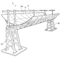
- FIG. 3 is a schematic perspective view for explaining the solar heat collecting device 8.
- the solar heat collecting device 8 includes a gantry 30 on the ground, and a heat collecting tube 12 and a reflecting plate 13 that are rotatably supported by the gantry 30.
- the solar heat collecting device 8 includes a rotating device that rotates the heat collecting tube 12 and the reflecting plate 13 following the sun.
- the reflection plate 13 is made of a highly reflective mirror or metal plate (for example, a steel plate or an aluminum plate).
- the reflection surface 13a of the reflection plate 13 is formed in a parabolic column shape.
- the heat collecting tube 12 is a tube extending linearly.
- the heat collecting tube 12 is covered with a vacuum glass tube for heat insulation.
- the heat collecting tube 12 is supported so that the center thereof is located at the focal point of the parabolic columnar reflecting surface 13 a of the reflecting plate 13.
- the sunlight reflected by the reflecting surface 13a is condensed at the focal point of the parabolic column surface, so that the heat collecting tube 12 located at the focal point can be efficiently heated.
- FIG. 4 is a flowchart for explaining a heat medium introduction method according to the embodiment of the present invention.
- FIG. 5A and FIG. 5B are views for explaining how the light shielding member is attached according to the embodiment of the present invention.
- FIG. 5A is a schematic front view of the solar heat collecting device 8
- FIG. 5B is a schematic side view of the solar heat collecting device 8.
- the light shielding member 40 is a cloth-like member. Although the kind of this cloth-like member is not particularly limited, synthetic fibers such as nylon and polyester are suitable because shrinkage hardly occurs. In the present embodiment, as shown in FIGS. 5A and 5B, the light shielding member 40 is attached so as to cover the upper portion 13 u and the lower portion 13 d of the reflective surface 13 a of the light shielding member 40. Yes.
- a fixing portion 41 for detachably fixing the light shielding member 40 to the reflecting plate 13 is provided at the end of the light shielding member 40.
- the light shielding member 40 may be a hook-and-loop fastener or a magnet, for example.
- the fixing portion 41 may be a string for binding the light shielding member 40 to the reflecting plate 13.
- the light shielding member 40 may be attached to the reflecting plate 13 by forming the fixing portion 41 in a bag shape and covering the reflecting plate 13 with the bag-shaped fixing portion 41.
- the explanation of the method of introducing the heat medium will be continued.
- the collection of sunlight on the heat collecting tube 12 is started (S12).
- the rotating device described above is operated to cause the heat collecting tube 12 and the reflecting plate 13 to follow the sun.
- the reflected light from the portion of the reflecting surface 13a of the reflecting plate 13 that is not covered with the light shielding member 40 is condensed on the heat collecting tube 12, and the heat collecting tube 12 is preheated.
- a heat medium is introduced into the heat collecting tube 12 (S14). Since the heat collecting tube 12 is preheated, the heat medium can be poured into the heat collecting tube 12 without solidifying.
- the collection of sunlight on the heat collection tube 12 is stopped (S16). That is, the rotating device is operated so that the reflecting surface 13a of the reflecting plate 13 does not face the sun. Finally, the light shielding member 40 is removed from the reflecting plate 13 (S18), and the introduction of the heat medium is completed.
- the heat collecting tube 12 When sunlight is collected on the heat collecting tube 12 without attaching the light shielding member 40 to the reflecting plate 13 in a state where no heat medium is introduced into the heat collecting tube 12, the heat collecting tube 12 becomes a so-called empty state. It may become hot and break. As in this embodiment, by attaching the light shielding member 40 so as to cover a part of the reflection surface 13a of the reflection plate 13, the amount of light collected on the heat collection tube 12 can be suppressed. It becomes possible to prevent the heat collecting tube 12 from being very high and to prevent the heat collecting tube 12 from being damaged.
- the heat medium introducing method according to the present embodiment is simply prepared by preparing a cloth-shaped light shielding member 40, attaching it to the reflecting plate 13 before introducing the heat medium, and removing it from the reflecting plate 13 after introducing the heat medium. Compared with the method of preheating by supplying an electric current to the heat tube, it is very simple and low cost.
- the light shielding member 40 is attached so as to be along the reflection surface 13a of the reflection plate 13, but is not necessarily limited to such an attachment form, and from the reflection surface 13a. It is sufficient that the light shielding member 40 is provided so that the reflected light does not reach the heat collecting tube 12. For example, the light shielding member 40 may be attached so as to hang vertically downward from the upper end of the reflecting plate 13.
- the light shielding member 40 is a cloth-like member, but when the reflecting plate 13 is a magnetic body, the light shielding member 40 may be a rubber magnet. In this case, the entire light shielding member 40 functions as a fixing portion for detachably fixing to the reflection plate 13.
- FIG. 6 (a) and 6 (b) are views for explaining an attachment mode of a light shielding member according to another embodiment of the present invention.
- FIG. 6A is a schematic front view of the heat collecting tube 12
- FIG. 6B is a schematic side view of the heat collecting tube 12.
- the heat collecting tube 12 is covered with a vacuum glass tube 60 for heat insulation.
- a light shielding member 62 is attached so as to cover the heat collecting tube 12 and the vacuum glass tube 60.
- the light shielding member 62 is a metallic cylindrical member, and is composed of two semi-cylindrical divided cylindrical members 63.
- the two divided cylindrical members 63 are fixed on the outer peripheral surface of the vacuum glass tube 60 by bolts 64 and nuts 65.
- the bolt 64 and the nut 65 function as a fixing portion for detachably fixing the light shielding member 62 to the heat collecting tube 12 and the vacuum glass tube 60.
- the light shielding member 62 is made of a so-called punching metal provided with a plurality of openings 66.
- the metal light shielding member 40 is prepared and attached so as to cover the heat collecting tube 12 and the vacuum glass tube 60 before introducing the heat medium, and the heat medium is introduced. Since it is simply removed from the heat collecting tube 12 and the vacuum glass tube 60 later, it is much simpler and less expensive than the above-described method of applying current to the heat collecting tube and preheating.
- the preheating temperature of the heat collecting tube 12 is affected by the aperture ratio of the light shielding member.
- the aperture ratio of the light shielding member is the area ratio of the reflection surface covered with the light shielding member 40 to the total reflection surface of the reflection plate 13 in the embodiment shown in FIGS. 5 (a) and 5 (b).
- the aperture ratio 100% of the light shielding member 40 is a state where the reflection surface 13a is not covered with the light shielding member 40 at all, and the aperture ratio 0% of the light shielding member 40 is that the reflection surface 13a is entirely covered with the light shielding member 40. It is in the state.
- the aperture ratio of the light shielding member is the area ratio of the surface of the heat collecting tube 12 covered with the light shielding member 62 to the entire surface of the heat collecting tube 12. is there.
- the opening ratio 100% of the light shielding member 62 is a state where the surface of the heat collecting tube 12 is not covered with the light shielding member 62 at all, and the opening ratio of the light shielding member 62 is 0% of the surface of the heat collecting tube 12. 62 is covered.
- T is the preheating temperature
- e (T) is the heat collecting tube heat radiation per unit length at the preheating temperature
- P DNI is the direct normal surface solar radiation intensity
- A is the width of the reflector 13
- ⁇ is the light collection efficiency.
- the width of the reflecting plate 13 means the opening width in the short direction of the reflecting plate 13.
- the preferable range of the aperture ratio r is 8% to 12%.
- the light shielding member is provided on one of the reflecting plate and the heat collecting tube, but the light shielding member may be provided on both the reflecting plate and the heat collecting tube.
- the present invention can be used for a solar heat collecting device used in a solar thermal power generation system.
Landscapes
- Engineering & Computer Science (AREA)
- Physics & Mathematics (AREA)
- Life Sciences & Earth Sciences (AREA)
- Sustainable Development (AREA)
- Sustainable Energy (AREA)
- Thermal Sciences (AREA)
- Chemical & Material Sciences (AREA)
- Combustion & Propulsion (AREA)
- Mechanical Engineering (AREA)
- General Engineering & Computer Science (AREA)
- Photovoltaic Devices (AREA)
Abstract
太陽熱収集装置(8)は、熱媒を流す集熱管(12)と、集熱管(12)に太陽光を集光する反射板(13)と、集熱管(12)に熱媒が導入される際に、反射板(13)の反射面(13a)の一部を覆うように取り付けられる遮光部材(40)とを備える。
Description
本発明は、太陽光を集光することで、集熱管内を流れる熱媒を加熱する太陽熱収集装置に関する。
反射鏡を用いて太陽光を集熱管に集光させて集熱管内を流れる熱媒を加熱し、加熱された熱媒を利用して蒸気を発生させ、蒸気タービンを回すことにより発電を行う太陽熱発電システムが知られている。太陽熱発電システムは、太陽光発電システムよりも導入費用が安い他に蓄熱により24時間の発電が可能である。従来では、熱媒にオイルを用いた太陽熱発電システムが提案されている(例えば特許文献1参照)。
近年、太陽熱発電システムに用いる熱媒として溶融塩が注目されている。溶融塩は沸点が高いため、溶融塩によれば運転温度を比較的高くでき高温蒸気を発生させることにより発電効率が向上する。
溶融塩は250℃程度で固化してしまうため、スタートアップやメンテナンス後に集熱管に溶融塩を流し込むとき、集熱管の温度が比較的低い状態にあると集熱管に熱を奪われて溶融塩が固化しうる。そのため、集熱管に溶融塩を流し込む前に集熱管を所定の温度以上に予熱しておく必要がある。
集熱管を予熱する一つの手法として、集熱管に電流を流すことが考えられる。電流を流すと、そのときのジュール熱で集熱管を温めることができる。
しかしながら、上記のような集熱管に電流を流す予熱方法では、非常に多くの電力が必要となり、コストが高くなるという課題がある。
本発明はこうした状況に鑑みてなされたものであり、その目的は、太陽熱収集装置において、低コストで集熱管を予熱できる技術を提供することにある。
上記課題を解決するために、本発明のある態様の太陽熱収集装置は、熱媒を流す集熱管と、集熱管に太陽光を集光する反射板と、集熱管に熱媒が導入される際に、反射板および/または集熱管の一部に取り付けられる遮光部材とを備える。
遮光部材は、反射板に対して着脱可能に固定するための固定部を備えてもよい。
遮光部材は、反射板の一部を覆うように設けられる布状部材であってもよい。
遮光部材は、集熱管の一部を覆うように設けられる金属部材であってもよい。金属部材は、複数の開口部が設けられた筒状体であってもよい。
本発明の別の態様は、熱媒を流す集熱管と、集熱管に太陽光を集光する反射板とを備える太陽熱収集装置における集熱管の予熱方法である。この予熱方法は、反射板および/または集熱管の一部に遮光部材を取り付けるステップと、反射板を用いて太陽光を集熱管に集光するステップとを備える。
本発明のさらに別の態様は、熱媒を流す集熱管と、集熱管に太陽光を集光する反射板とを備える太陽熱収集装置において、集熱管に熱媒を導入するための熱媒導入方法である。この熱媒導入方法は、反射板および/または集熱管の一部に遮光部材を取り付けるステップと、反射板を用いて太陽光を集熱管に集光し、集熱管を予熱するステップと、予熱された集熱管に熱媒を流し込むステップと、集熱管への太陽光の集光を停止するステップと、反射板および/または集熱管から遮光部材を取り外すステップとを備える。
なお、以上の構成要素の任意の組合せ、本発明の表現を装置、方法、システムなどの間で変換したものもまた、本発明の態様として有効である。
本発明によれば、太陽熱収集装置において、低コストで集熱管を予熱できる。
以下、各図面に示される同一または同等の構成要素、部材には、同一の符号を付するものとし、適宜重複した説明は省略する。また、各図面における部材の寸法は、理解を容易にするために適宜拡大、縮小して示される。また、各図面において実施の形態を説明する上で重要ではない部材の一部は省略して表示する。
図1は、本発明の実施形態に係る太陽熱発電システム100を説明するための図である。太陽熱発電システム100は、集光エリア121、蓄熱エリア122、発電エリア123の3つのエリアを含む。
集光エリア121は、主に太陽熱収集装置8を含む。太陽熱収集装置8は、熱媒を流す複数の集熱管から成る熱媒流路11と、太陽光を集熱管に集光して熱媒を加熱する複数の反射板13とを備える。加熱された熱媒は、蓄熱エリア122に送られる。
蓄熱エリア122は、ホットタンク102と、コールドタンク103とを含む。加熱された熱媒の熱をホットタンク102に蓄えておくことにより、必要なときに発電できる。例えば夜間や日中の悪天候時の発電が可能となる。
発電エリア123は、蒸気発生器104と、蒸気タービン発電機106と、復水器108とを含む。蒸気発生器104は、冷却水と加熱された熱媒との熱交換により蒸気を発生させ、蒸気タービン発電機106は蒸気によりタービンを回転させる。この回転により発電する。復水器108は蒸気を冷却水に戻す。
図2は、本発明の実施形態に係る太陽熱収集装置8を説明するための図である。図2に示すように、太陽熱収集装置8は、複数(図1では4つ)の集光ユニット10と、連結流路50とを含む。各集光ユニット10は、熱媒流路11と、複数の反射板13とを含む。
各熱媒流路11は、U字状に形成され、互いに平行な長直線部11aおよび11bと、長直線部11aおよび11bの一端部同士をつなぐ短直線部11cとから成る。長直線部11aおよび11bは、それぞれ、直線状に配置された複数の集熱管12から成る。短直線部11cは、連結配管14から成る。長直線部11a、11bの長さAは、約100~200mであってよい。また、各集熱管12の長さは、約10~20mであってよい。また、長直線部11aは10~20本の集熱管12から構成されてよい。また、短直線部11cの長さBは20~30mであってよい。
熱媒流路11の集熱管12内には、太陽熱を受ける熱媒としての溶融塩が流れる。溶融塩は、太陽熱収集装置において従来使用されてきた合成オイルよりも沸点が高いため、より高温に温められる。これにより、太陽熱発電システム100の発電効率が向上する。一方で、溶融塩は、250℃程度で固化してしまう。溶融塩は、運転時は太陽熱で加熱されているため基本的に固化することはないが、例えばスタートアップ時やメンテナンス後に集熱管12に溶融塩を流し込むとき、集熱管12の温度が比較的低い状態にあると集熱管12に熱を奪われて固化しうる。そこで、本実施形態では、集熱管12に溶融塩を流し込む前に、集熱管12を所定の温度以上に予熱しておく。集熱管12への溶融塩の導入方法については後述する。
連結流路50は、環状の流路であり、各熱媒流路11と接続される。また連結流路50は、蓄熱エリア122のホットタンク102およびコールドタンク103とも接続される。したがって、連結流路50を介して、各熱媒流路11と、ホットタンク102およびコールドタンク103とが連結される。連結流路50にはコールドタンク103から熱媒が流れこむ。連結流路50を流れる熱媒は、各熱媒流路11の長直線部11aに流し込まれる。長直線部11aの集熱管12を通って加熱された熱媒は、連結配管14を通って長直線部11bに流れる。長直線部11bの集熱管12を通って加熱された熱媒は、連結流路50に戻り、ホットタンク102に流れ込む。
図3は、太陽熱収集装置8を説明するための概略斜視図である。図3に示すように、太陽熱収集装置8は、地盤上の架台30と、架台30により回転可能に支持された集熱管12および反射板13とを備える。また、太陽熱収集装置8は、太陽に追従して集熱管12および反射板13を回転させる回転装置を備える。
反射板13は、高反射率の鏡もしくは金属板(例えばスチール板またはアルミ板)から成る。反射板13の反射面13aは、放物柱面状に形成されている。集熱管12は、直線的に延びる管である。集熱管12は、断熱のために真空ガラス管で覆われている。集熱管12は、その中心が反射板13の放物柱面状の反射面13aの焦点に位置するように支持されている。反射面13aで反射した太陽光は、放物柱面の焦点に集光するので、その焦点に位置する集熱管12を効率的に加熱できる。
図4は、本発明の実施形態に係る熱媒の導入方法を説明するためのフローチャートである。
本実施形態に係る熱媒導入方法においては、まず、反射板13の一部に遮光部材を取り付ける(S10)。図5(a)および図5(b)は、本発明の実施形態に係る遮光部材の取付態様を説明するための図である。図5(a)は、太陽熱収集装置8の概略正面図であり、図5(b)は、太陽熱収集装置8の概略側面図である。
本実施形態において、遮光部材40は、布状部材である。この布状部材の種類は特に限定されないが、縮みが生じにくいことから例えばナイロンやポリエステル等の合成繊維が好適である。本実施形態では、図5(a)および図5(b)に示すように、遮光部材40は、遮光部材40の反射面13aのうち、上方部分13uおよび下方部分13dを覆うように取り付けられている。
図5(a)および図5(b)に示すように、遮光部材40の端部には、遮光部材40を反射板13に対して着脱可能に固定するための固定部41が設けられている。遮光部材40は、例えば面ファスナーや磁石等であってよい。あるいは、固定部41は、遮光部材40を反射板13に括り付けるための紐であってもよい。あるいは、固定部41を袋状に形成し、該袋状の固定部41を反射板13に被せることで遮光部材40を反射板13に取り付けてもよい。
図4に戻り、熱媒の導入方法の説明を続ける。反射板13に遮光部材40を取り付けた後、集熱管12への太陽光の集光を開始する(S12)。具体的には、上述の回転装置を作動させ、集熱管12および反射板13を太陽に追従させる。これにより、反射板13の反射面13aのうち、遮光部材40で覆われていない部分からの反射光が集熱管12に集光し、集熱管12が予熱される。
集熱管12が所定の温度(例えば300℃程度)に予熱された後、集熱管12内に熱媒を導入する(S14)。集熱管12が予熱されているため、固化することなく熱媒を集熱管12内に流し込むことができる。
集熱管12内に熱媒を導入した後、集熱管12への太陽光の集光を停止する(S16)。すなわち、反射板13の反射面13aが太陽の方向を向かないように回転装置を作動させる。最後に、反射板13から遮光部材40を取り外し(S18)、熱媒の導入が完了する。
集熱管12内に熱媒が導入されていない状態で、反射板13に遮光部材40を取り付けずに集熱管12に太陽光を集光した場合、集熱管12がいわゆる空焚き状態となって非常に高温になり、破損するおそれがある。本実施形態のように、反射板13の反射面13aの一部を覆うように遮光部材40を取り付けることにより、集熱管12への集光量を抑制することができるため、集熱管12の温度が非常に高くなることが防止され、集熱管12の破損を防ぐことができる。本実施形態に係る熱媒導入方法は、布状の遮光部材40を用意し、熱媒の導入前に反射板13に取り付け、熱媒導入後に反射板13から取り外すだけであるので、上述した集熱管に電流を流して予熱する方法に比べて、非常に簡易且つ低コストである。
図5(a)および図5(b)では、遮光部材40は反射板13の反射面13aに沿うように取り付けられているが、必ずしもこのような取付形態に限定されず、反射面13aからの反射光が集熱管12に到達しないように遮光部材40が設けられていればよい。例えば、遮光部材40は、反射板13の上端から鉛直下方に垂れ下がるように取り付けられてもよい。
上記実施形態では、遮光部材40を布状部材としたが、反射板13が磁性体である場合には、遮光部材40はラバー磁石であってもよい。この場合、遮光部材40の全体が、反射板13に対して着脱可能に固定するための固定部として機能する。
図6(a)および図6(b)は、本発明の別の実施形態に係る遮光部材の取付態様を説明するための図である。図6(a)は、集熱管12の概略正面図であり、図6(b)は、集熱管12の概略側面図である。
図6(a)および図6(b)に示すように、集熱管12は、断熱のために真空ガラス管60で覆われている。本実施形態では、集熱管12および真空ガラス管60を覆うように遮光部材62が取り付けられている。この遮光部材62は、金属製の筒状部材であり、半円柱状の2つの分割筒状部材63から成る。2つの分割筒状部材63は、ボルト64およびナット65によって真空ガラス管60の外周面上に固定される。ボルト64およびナット65は、遮光部材62を集熱管12および真空ガラス管60に対して着脱可能に固定するための固定部として機能する。
図6(a)に示すように、遮光部材62は、複数の開口部66が設けられたいわゆるパンチングメタルから成る。遮光部材62で集熱管12を覆うことにより、集熱管12への集光量を抑制することができるため、集熱管12の温度が非常に高くなることが防止され、集熱管12の破損を防ぐことができる。本実施形態に係る遮光部材62の取付態様を用いた場合も、金属製の遮光部材40を用意し、熱媒の導入前に集熱管12および真空ガラス管60を覆うように取り付け、熱媒導入後に集熱管12および真空ガラス管60から取り外すだけであるので、上述した集熱管に電流を流して予熱する方法に比べて、非常に簡易且つ低コストである。
図5(a)および図5(b)並びに図6(a)および図6(b)で説明した遮光部材の取付態様において、集熱管12の予熱温度は、遮光部材の開口率に影響される。
遮光部材の開口率とは、図5(a)および図5(b)に示す態様では、反射板13の全反射面に対する、遮光部材40で覆われた反射面の面積比率である。例えば遮光部材40の開口率100%とは、反射面13aが全く遮光部材40で覆われていない状態であり、遮光部材40の開口率0%とは反射面13aが全て遮光部材40で覆われた状態である。
また、図6(a)および図6(b)に示す態様では、遮光部材の開口率とは、集熱管12の全表面に対する、遮光部材62で覆われた集熱管12の表面の面積比率である。例えば遮光部材62の開口率100%とは、集熱管12の表面が全く遮光部材62で覆われていない状態であり、遮光部材62の開口率0%とは集熱管12の表面が全て遮光部材62で覆われた状態である。
図5(a)および図5(b)並びに図6(a)および図6(b)のいずれの態様においても、遮光部材40の最適な開口率rは、以下の数式によって計算される。
r=e(T)/(PDNI×A×η)
ここで、Tは予熱温度、e(T)は予熱温度における単位長当たりの集熱管放熱量、PDNIは直達法線面日射強度、Aは反射板13の幅、ηは集光効率である。なお、反射板13の幅とは、反射板13の短手方向における開口幅を意味する。
r=e(T)/(PDNI×A×η)
ここで、Tは予熱温度、e(T)は予熱温度における単位長当たりの集熱管放熱量、PDNIは直達法線面日射強度、Aは反射板13の幅、ηは集光効率である。なお、反射板13の幅とは、反射板13の短手方向における開口幅を意味する。
反射板13の幅が6m、焦点距離が1.8m、集光管径が70mmという条件で計算したところ、開口率rの好適な範囲は、8%~12%であった。
以上、本発明を実施の形態をもとに説明した。この実施の形態は例示であり、それらの各構成要素や各処理プロセスの組合せにいろいろな変形例が可能なこと、またそうした変形例も本発明の範囲にあることは当業者に理解されるところである。
例えば上述の実施形態では、反射板と集熱管の一方に遮光部材を設けたが、反射板と集熱管の両方に遮光部材を設けてもよい。
8 太陽熱収集装置、 10 集光ユニット、 11 熱媒流路、 12 集熱管、 13 反射板、 30 架台、 40、62 遮光部材、 41 固定部、 60 真空ガラス管、 63 分割筒状部材、 100 太陽熱発電システム。
本発明は、太陽熱発電システムで使用される太陽熱収集装置に利用できる。
Claims (7)
- 熱媒を流す集熱管と、
前記集熱管に太陽光を集光する反射板と、
前記集熱管に前記熱媒が導入される際に、前記反射板および/または前記集熱管の一部に取り付けられる遮光部材と、
を備えることを特徴とする太陽熱収集装置。 - 前記遮光部材は、前記反射板に対して着脱可能に固定するための固定部を備えることを特徴とする請求項1に記載の太陽熱収集装置。
- 前記遮光部材は、前記反射板の一部を覆うように設けられる布状部材であることを特徴とする請求項1または2に記載の太陽熱収集装置。
- 前記遮光部材は、前記集熱管の一部を覆うように設けられる金属部材であることを特徴とする請求項1または2に記載の太陽熱収集装置。
- 前記金属部材は、複数の開口部が設けられた筒状体であることを特徴とする請求項4に記載の太陽熱収集装置。
- 熱媒を流す集熱管と、前記集熱管に太陽光を集光する反射板とを備える太陽熱収集装置における、前記集熱管の予熱方法であって、
前記反射板および/または前記集熱管の一部に遮光部材を取り付けるステップと、
前記反射板を用いて太陽光を前記集熱管に集光するステップと、
を備えることを特徴とする予熱方法。 - 熱媒を流す集熱管と、前記集熱管に太陽光を集光する反射板とを備える太陽熱収集装置において、前記集熱管に前記熱媒を導入するための熱媒導入方法であって、
前記反射板および/または前記集熱管の一部に遮光部材を取り付けるステップと、
前記反射板を用いて太陽光を前記集熱管に集光し、前記集熱管を予熱するステップと、
予熱された前記集熱管に前記熱媒を流し込むステップと、
前記集熱管への太陽光の集光を停止するステップと、
前記反射板および/または前記集熱管から前記遮光部材を取り外すステップと、
を備えることを特徴とする熱媒導入方法。
Priority Applications (1)
| Application Number | Priority Date | Filing Date | Title |
|---|---|---|---|
| PCT/JP2015/065271 WO2016189702A1 (ja) | 2015-05-27 | 2015-05-27 | 太陽熱収集装置、集熱管の予熱方法および熱媒導入方法 |
Applications Claiming Priority (1)
| Application Number | Priority Date | Filing Date | Title |
|---|---|---|---|
| PCT/JP2015/065271 WO2016189702A1 (ja) | 2015-05-27 | 2015-05-27 | 太陽熱収集装置、集熱管の予熱方法および熱媒導入方法 |
Publications (1)
| Publication Number | Publication Date |
|---|---|
| WO2016189702A1 true WO2016189702A1 (ja) | 2016-12-01 |
Family
ID=57392999
Family Applications (1)
| Application Number | Title | Priority Date | Filing Date |
|---|---|---|---|
| PCT/JP2015/065271 Ceased WO2016189702A1 (ja) | 2015-05-27 | 2015-05-27 | 太陽熱収集装置、集熱管の予熱方法および熱媒導入方法 |
Country Status (1)
| Country | Link |
|---|---|
| WO (1) | WO2016189702A1 (ja) |
Cited By (1)
| Publication number | Priority date | Publication date | Assignee | Title |
|---|---|---|---|---|
| CN113587454A (zh) * | 2021-08-18 | 2021-11-02 | 河海大学 | 一种磁场调控太阳能集热装置 |
Citations (5)
| Publication number | Priority date | Publication date | Assignee | Title |
|---|---|---|---|---|
| JPS55166360U (ja) * | 1979-05-17 | 1980-11-29 | ||
| JPS58213152A (ja) * | 1982-06-03 | 1983-12-12 | Matsushita Electric Ind Co Ltd | 太陽熱集熱装置 |
| WO2010032095A2 (en) * | 2008-09-18 | 2010-03-25 | Kloben S.A.S. Di Turco Adelino Ec. | Non-tracking solar collector device |
| US20100236600A1 (en) * | 2007-06-08 | 2010-09-23 | Sopogy, Inc. | Parking solar energy collectors |
| WO2013019670A2 (en) * | 2011-07-29 | 2013-02-07 | Babcock & Wilcox Power Generation Group, Inc. | Shop assembled vertical serpentine flow molten salt solar receiver |
-
2015
- 2015-05-27 WO PCT/JP2015/065271 patent/WO2016189702A1/ja not_active Ceased
Patent Citations (5)
| Publication number | Priority date | Publication date | Assignee | Title |
|---|---|---|---|---|
| JPS55166360U (ja) * | 1979-05-17 | 1980-11-29 | ||
| JPS58213152A (ja) * | 1982-06-03 | 1983-12-12 | Matsushita Electric Ind Co Ltd | 太陽熱集熱装置 |
| US20100236600A1 (en) * | 2007-06-08 | 2010-09-23 | Sopogy, Inc. | Parking solar energy collectors |
| WO2010032095A2 (en) * | 2008-09-18 | 2010-03-25 | Kloben S.A.S. Di Turco Adelino Ec. | Non-tracking solar collector device |
| WO2013019670A2 (en) * | 2011-07-29 | 2013-02-07 | Babcock & Wilcox Power Generation Group, Inc. | Shop assembled vertical serpentine flow molten salt solar receiver |
Cited By (1)
| Publication number | Priority date | Publication date | Assignee | Title |
|---|---|---|---|---|
| CN113587454A (zh) * | 2021-08-18 | 2021-11-02 | 河海大学 | 一种磁场调控太阳能集热装置 |
Similar Documents
| Publication | Publication Date | Title |
|---|---|---|
| JP5868809B2 (ja) | 発電プラントおよび熱供給方法 | |
| US20130133324A1 (en) | Hybrid solar power plant | |
| JP4477057B2 (ja) | ビームダウン方式太陽熱発電装置 | |
| EP2472111A1 (en) | Solar light condensing system | |
| US20150000277A1 (en) | Solar power plants and energy storage systems for solar power plants | |
| JP5851342B2 (ja) | ハイブリッド型太陽熱温水器システム | |
| JP2002522908A (ja) | 光起電力装置 | |
| WO2016189702A1 (ja) | 太陽熱収集装置、集熱管の予熱方法および熱媒導入方法 | |
| CN102878699A (zh) | 混合型太阳能集中装置 | |
| JP6543711B2 (ja) | 太陽熱収集装置 | |
| JP6543710B2 (ja) | 加熱装置 | |
| CN107709892B (zh) | 加热系统 | |
| JP2008286511A (ja) | 太陽光エネルギー湯沸し装置 | |
| WO2017002262A1 (ja) | 加熱装置 | |
| WO2016189703A1 (ja) | 太陽熱収集装置および集熱管の予熱方法 | |
| CN107709891B (zh) | 太阳能热收集装置的接地构造、太阳能热收集装置和太阳能热发电系统 | |
| KR100666056B1 (ko) | 태양열을 이용한 발전시스템 | |
| JP2013113496A (ja) | トラフ型太陽光集光装置及びそれを用いた太陽熱発電装置 | |
| CN104821775A (zh) | 太阳能发电系统 | |
| CN205316716U (zh) | 光热发电跟踪装置 | |
| JP3039163U (ja) | 太陽光、熱エネルギーの有効利用機器システム | |
| CN108375206B (zh) | 一种槽式太阳能连接系统及其方法 | |
| CN115164418A (zh) | 宽开口槽式太阳能聚光器 | |
| JP2003041907A (ja) | 集光レンズを用いて太陽光を利用する全ての技術。 | |
| JP2008198965A (ja) | 鏡集光発電機 |
Legal Events
| Date | Code | Title | Description |
|---|---|---|---|
| 121 | Ep: the epo has been informed by wipo that ep was designated in this application |
Ref document number: 15893336 Country of ref document: EP Kind code of ref document: A1 |
|
| NENP | Non-entry into the national phase |
Ref country code: DE |
|
| 122 | Ep: pct application non-entry in european phase |
Ref document number: 15893336 Country of ref document: EP Kind code of ref document: A1 |
|
| NENP | Non-entry into the national phase |
Ref country code: JP |