WO2016186197A1 - ネットワーク装置及び制御方法 - Google Patents
ネットワーク装置及び制御方法 Download PDFInfo
- Publication number
- WO2016186197A1 WO2016186197A1 PCT/JP2016/064990 JP2016064990W WO2016186197A1 WO 2016186197 A1 WO2016186197 A1 WO 2016186197A1 JP 2016064990 W JP2016064990 W JP 2016064990W WO 2016186197 A1 WO2016186197 A1 WO 2016186197A1
- Authority
- WO
- WIPO (PCT)
- Prior art keywords
- network device
- display
- port
- information
- network
- Prior art date
- Legal status (The legal status is an assumption and is not a legal conclusion. Google has not performed a legal analysis and makes no representation as to the accuracy of the status listed.)
- Ceased
Links
Images




Classifications
-
- H—ELECTRICITY
- H04—ELECTRIC COMMUNICATION TECHNIQUE
- H04L—TRANSMISSION OF DIGITAL INFORMATION, e.g. TELEGRAPHIC COMMUNICATION
- H04L12/00—Data switching networks
- H04L12/28—Data switching networks characterised by path configuration, e.g. LAN [Local Area Networks] or WAN [Wide Area Networks]
- H04L12/46—Interconnection of networks
Definitions
- the present invention relates to a technology for supporting operation management of a communication network.
- LANs Local Area Networks
- LAN installation, operation management, and the like require specialized knowledge, they are usually performed by a specialist engineer (hereinafter referred to as a network administrator).
- a network administrator connects a device such as a personal computer (hereinafter referred to as a PC) to each port of a network device such as a switching hub or a router via a LAN cable.
- the network administrator monitors a communication state such as a communication amount and a communication speed between the network device and another device for each port.
- Various techniques for supporting such LAN installation and operation management have been proposed in the past, and examples thereof include the techniques disclosed in Patent Documents 1 to 3.
- the network monitoring device disclosed in Patent Document 1 has a plurality of ports, and a relay device (network device) to be monitored is connected to each port.
- This relay device also has a plurality of ports, and a PC is connected to each port.
- the network monitoring apparatus acquires information (for example, communication amount) indicating a communication state between the relay device and the PC from the relay device, and displays the information on the display unit of the own device.
- the network administrator can grasp the communication state between the relay device and the PC for each port by confirming the display content of the display unit.
- the network device disclosed in Patent Document 2 includes a plurality of ports for inserting a network cable such as a LAN cable, an indicator corresponding to each port, and a display for displaying a character string.
- the indicator and the display are controlled by a user operation using a management tool such as Telnet or EMS.
- a management tool such as Telnet or EMS.
- Telnet Telnet
- the network administrator in the management room etc. operates the management tool to Enter information to identify
- the management tool acquires necessary information with reference to the database storing the setting information of the network device, turns on an indicator corresponding to the port specified based on the information, and displays related information on the display. Thereby, it is possible to give an instruction to a worker who performs work at a remote place.
- the network connection device disclosed in Patent Document 3 includes a plurality of input / output ports arranged in a horizontal row and three LEDs (one for each input / output port in a direction orthogonal to the input / output port arrangement direction). That is, a total of three LED groups arranged in a horizontal row). Each of the three rows of LED groups is assigned an identifier of communication 1 to 3, respectively.
- this network connection device turns on the LED of the corresponding input / output port in the communication 1 LED group. Thereafter, when data is transmitted / received between different input / output ports, the LED of the corresponding input / output port in the LED group of communication 2 is turned on.
- VLAN Virtual LAN Identifier
- VLAN refers to a technique for logically dividing a LAN segment within the switching hub
- VLANID is an identifier for identifying each segment.
- the network administrator when the internal network is divided into a plurality of segments using VLAN, it is necessary to manage the VLAN ID assigned to each port of the switching hub.
- a LAN is configured using a PoE (Power over Ethernet (registered trademark)) compatible switching hub that supplies power to other devices via a LAN cable
- the network administrator when a LAN is configured using a PoE (Power over Ethernet (registered trademark)) compatible switching hub that supplies power to other devices via a LAN cable, the network administrator must It is necessary to monitor the power supply status from other devices to other devices.
- the network to be managed by the network administrator includes a VLAN-compatible switching hub or a PoE-compatible switching hub, the network administrator assigns information regarding the setting of the switching hub (for example, assigning a VLAN ID to each port). Information) and information indicating the state of the switching hub (for example, information indicating the amount of power supplied from the switching hub to other devices) must be grasped and managed.
- the network monitoring device disclosed in Patent Document 1 can acquire information related to the communication status between the relay device and the PC, but cannot acquire information related to the setting and status of the relay device main body.
- the network connection device disclosed in Patent Literature 3 can acquire information related to the transmission / reception status between the input / output ports of the own device, but cannot acquire information related to the setting and status of the own device.
- the network administrator can acquire information related to the settings and status of the network device body using Telnet.
- Telnet login authority it is needless to say that Telnet login authority is required, and it is necessary to fully understand various commands in Telnet.
- Telnet is a CUI-based user interface
- command execution results are displayed as character strings and the like, and it is necessary to interpret these character strings in order to grasp the command execution results.
- information is acquired using Telnet, there is a concern that accidents such as rewriting or erasing the information due to erroneous input of a command or the like may occur.
- the present invention has been made in view of the circumstances described above, and it is an object of the present invention to provide a technique that allows a network administrator to easily grasp information related to settings and states of network devices.
- information is acquired from one or more ports to which a communication cable is connected, display means provided for each port, and a storage device that stores information related to settings or states of network devices. And a control unit that performs display control of each display unit according to the information.
- information relating to the setting and status of the network device is displayed on each display means.
- the display means corresponding to one port is composed of a plurality of light emitting elements
- the various information is displayed by the light emission pattern of each light emitting element.
- the user can intuitively grasp information regarding the setting and status of the network device without an operation requiring specialized knowledge such as command input.
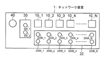
- FIG. 1 is a front view of a network device 1 according to an embodiment of the present invention.
- the network device 1 is a switching hub that supports VLAN and PoE technologies.
- the network device 1 relays communication between devices connected to a port to which the same VLAN ID is assigned in an in-house LAN composed of a plurality of VLANs.
- the network device 1 supplies power to a device installed in a place where power supply is difficult.
- the network device 1 supplies power to one device in one power supply process.
- the display unit 20 includes LEDs 200A_n and 200B_n corresponding to the port 10_n.
- the LEDs 200A_m and 200B_m are turned on. At this time, both the LEDs 200A_m and 200B_m may be turned on, or only one of the LEDs 200A_m or 200B_m may be turned on.
- the display mode of VLANID by the light emission pattern of LED200A_n and 200B_n is as follows.
- FIG. 2 is a diagram illustrating a correspondence relationship between the VLANID and the light emission patterns that the LEDs 200A_n and 200B_n can take. As shown in FIG.
- the relationship between the LED lighting color and light emission pattern and VLANID is merely an example, and may be changed as appropriate.
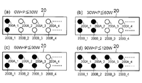
- FIGS. 3A to 3D show display modes when the power supply amount P to other devices is 0 W ⁇ P ⁇ 30 W, 30 W ⁇ P ⁇ 60 W, 60 W ⁇ P ⁇ 90 W, and 90 W ⁇ P ⁇ 120 W, respectively. Is shown.
- the network device 1 when 0W ⁇ P ⁇ 30W, the network device 1 turns on the LED 200A_1 and the LED 200B_1.
- FIG. 3A when 0W ⁇ P ⁇ 30W, the network device 1 turns on the LED 200A_1 and the LED 200B_1.
- a plurality of types of information can be displayed using the display unit 20.
- a state for displaying the communication state of each port (in this embodiment, the communication speed of data communication via each port) is displayed in display mode 1
- a state for displaying the VLAN ID assigned to each port is displayed in display mode 2.
- a state in which the power supply state from the network device 1 to other devices is displayed is referred to as a display mode 3.
- the display mode 1 is initially set.
- the switch 40 is an operation unit for inputting an operation for switching the display modes 1 to 3. More specifically, when the switch 40 is operated under the condition of the display mode 1, the network device 1 switches the display mode from the display mode 1 to the display mode 2. Thereafter, when the switch 40 is operated, the network device 1 switches the display mode from the display mode 2 to the display mode 3. When the switch 40 is further operated, the network device 1 switches the display mode from the display mode 3 to the display mode 1.
- the display unit 30 includes LEDs 300_1 and 300_2.
- the display unit 30 displays the display mode of the network device 1 by turning on or off.
- Each of the LEDs 300_1 and 300_2 is a single color LED.
- both the LEDs 300_1 and 300_2 are turned off.
- the display mode is the display mode 2
- only the LED 300_1 is lit
- the display mode is the display mode 3
- only the LED 300_2 is lit.
- the network administrator can grasp the display mode of the network device 1 through the light emission patterns of the LEDs 300_1 and 300_2.
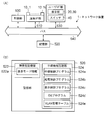
- FIG. 4A is a diagram illustrating a configuration example of the network device 1.
- the network device 1 includes a control unit 500, a communication interface (hereinafter referred to as I / F) unit 510, a storage unit 520, a user I / F unit 530, and data exchange between these components.
- I / F communication interface
- the user I / F unit 530 includes a display unit 20, a display unit 30, and a switch 40.
- NIC Network Interface Card
- FIG. 4B is a diagram illustrating a configuration example of the storage unit 520.
- the storage unit 520 includes a volatile storage unit 522 and a nonvolatile storage unit 524.
- the volatile storage unit 522 is a volatile memory such as a RAM (Random Access Memory).
- the volatile storage unit 522 is used by the control unit 500 as a work area when executing each program to be described later.
- the volatile storage unit 522 is used as an area for storing display mode information 522a indicating the display mode of the network device 1.
- the nonvolatile storage unit 524 is a nonvolatile memory such as a flash ROM (Read Only Memory). As shown in FIG. 4B, in the nonvolatile storage unit 524 of this embodiment, a relay control program 524a, a power supply control program 524b, a display control program 524c, and an OS program 524d are stored in advance.
- the nonvolatile storage unit 524 stores a MAC (Media Access Control) address table (not shown in FIG. 4B) and data representing information related to the settings of the network device 1. .
- MAC Media Access Control
- An example of this type of data is the VLAN management table 524e.
- the description of the MAC address table is omitted because there is no particular difference from that of a general switching hub.
- the VLAN management table 524e is a table for managing the VLAN ID assigned to each port of the network device 1.
- the relay control program 524a is a program that causes the control unit 500 to implement relay control such as data communication performed between devices in the VLAN.
- the control unit 500 operating according to the relay control program 524a measures the communication speed (for example, data transmission / reception amount per unit time) of data communication through the port for each port 10_n, and represents the measurement result.
- a process of writing data (hereinafter, communication state data) in a predetermined storage area of the volatile storage unit 522 is also executed.
- the power supply control program 524b is a program that causes the control unit 500 to realize power supply control from the network device 1 to another device.
- the control unit 500 operating according to the power supply control program 524b performs, in addition to performing the power supply control, data (hereinafter referred to as power supply state data) representing the power supply amount per unit time in a predetermined amount of the volatile storage unit 522. A process of writing to the storage area is also executed.
- the OS program 524d is software for causing the control unit 500 to realize an OS (Operating System).
- the display control program 524c is a program that causes the control unit 500 to execute processing that clearly shows the features of the present invention. More specifically, the display control program 524c is a program for controlling display contents of the display units 20 and 30 (that is, light emission patterns of the LEDs 200A_n and 200B_n and the LEDs 300_1 and 300_2). The details of the display control operation executed by the control unit 500 according to the display control program 524c will be clarified in the operation example in order to avoid duplication of explanation.
- the control unit 500 is a CPU (Central Processing Unit), for example, and is a controller that controls all or part of the network device 1.
- the control unit 500 functions as a control center of the network device 1 by executing each program stored in the storage unit 520 (more precisely, the nonvolatile storage unit 524).
- the control unit 500 reads out the OS program 524d from the nonvolatile storage unit 524 to the volatile storage unit 522 and starts executing it when the power (not shown) of the network device 1 is turned on.
- the control unit 500 that operates according to the OS program 524d and realizes the OS reads the relay control program 524a, the power supply control program 524b, and the display control program 524c from the nonvolatile storage unit 524 to the volatile storage unit 522. Run the program in parallel.
- the above is the configuration of the network device 1.
- the employee's PC belonging to the department 1 is connected to the ports 10_1 to 10_5 of the network apparatus 1, and the employee's PC belonging to the department 2 is connected to the ports 10_6 to 10_10 of the network apparatus 1.
- the employees' PCs belonging to the department 3 are connected to the ports 10_11 to 10_15 of the network device 1.
- the PC connected to the port 10_15 is installed in a place where power supply is difficult, and power is supplied through the LAN cable.
- the maximum power that can be supplied to the network device 1 is 120 W.
- the LEDs 200A_n and 200B_n are not distinguished, they are described as LEDs 200_n.
- FIG. 5 is a flowchart showing the contents of display control processing executed by the control unit 500.
- the control unit 500 determines whether or not there is a switching instruction (step S10).
- the switching instruction is generated when a signal generated when the switch 40 is pressed is given to the control unit 500.
- the control unit 500 determines whether or not there is a switching instruction based on whether or not the signal is received.
- the determination result of step S10 is No, and the control unit 500 executes the process of step S30.
- step S30 the controller 500 identifies the current display mode with reference to the display mode information 522a.
- step S10 When the employee A presses the switch 40 to confirm the VLAN ID assigned to the ports 10_1 to 10_15, the determination result in step S10 is Yes, and the control unit 500 displays the display mode information 522a from the data indicating the display mode 1.
- the data indicating mode 2 is updated (step S20).
- step S30 the control unit 500 executes step S30 and executes a display control process corresponding to the display mode 2 (step S50). More specifically, the controller 500 reads the VLAN ID assigned to the ports 10_1 to 10_15 from the VLAN management table 524e. Then, the control unit 500 turns on the LED 300_1 and turns on the LED 200_n with a light emission pattern corresponding to the VLANID assigned to the port 10_n.
- the light emission patterns of the LEDs 200A_1 to 200A_5 and 200B_1 to 200B_5 are (off, off)
- the light emission patterns of the LEDs 200A_5 to 200A_10 and 200B_5 to 200B_10 are (off, yellow)
- the LED 200A_10 Assume that the light emission patterns of .about.200A_15 and 200B_10 to 200B_15 are turned off (green, off).
- Employee A confirms this light emission pattern, and in Company B's internal LAN, grasps that VLAN ID 1 is assigned to department 1, 2 is assigned to department 2, and 3 is assigned to department 3. (See FIG. 2).
- step S10 the determination result in step S10 is Yes, and the control unit 500 updates the display mode information 522a from the data indicating the display mode 2 to the data indicating the display mode 3 (step S20). Thereafter, the control unit 500 executes step S30 and executes a display control process corresponding to the display mode 3 (step S60). More specifically, the control unit 500 turns on the LEDs 200_1 to 200_4 with a light emission pattern corresponding to the power supply amount represented by the power supply state data.
- the network administrator can grasp the assignment of VLANID and the power supply state from the network device 1 to other devices only by operating the switch 40, and it is not necessary to memorize commands or the like.
- the VLAN ID assigned to each port and the power supply state from the network device 1 to other devices are displayed as an LED light emission pattern in an easy-to-understand manner to the network administrator. That is, according to the present embodiment, the network administrator can easily grasp information related to the settings and status of the network device 1 main body.
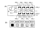
- FIG. 6A is a front view of the network device 1 according to this modification.
- the port 10_n in the present modification is a LAN port to which a LAN cable is connected, and has a convex opening.
- An LED 200B_n is provided on the right shoulder of the opening of the port 10_n, and an LED 200A_n is provided on the left shoulder.
- the LED 200A_n and the LED 200B_n are two-color light emitting LEDs capable of emitting two colors, green and orange, and can take five states: off, green flashing, green lighting, orange flashing, and orange lighting.
- these five states are distinguished by hatching shown in FIG.
- the display mode 1 in the network device 1 of this modification is a mode for displaying the communication speed and communication state (whether the link is lost, the link is established, or the data is being transferred) of each port.
- the display mode 2 is a display mode for displaying whether or not a loop has occurred
- the display mode 3 is a display mode for displaying a VLANID (hereinafter abbreviated as VID) assigned to the port 10_n.
- VID VLANID
- the communication speed of the data communication through the port 10_n is displayed using the LED 200B_n, and the state of the data communication through the port 10_n (whether the link is established or the like) is displayed using the LED 200A_n.
- the control unit 500 turns off the LED 200A_n if the data communication via the port 10_n is in a link lost state, and turns on the LED 200A_n in green if the link is in an established state. If transfer is in progress, the LED 200A_n blinks in green. Therefore, if the physical layer of data communication through the port 10_n is 100BASE-TX and data is being transferred, the display state of the LED 200A_n and the LED 200B_n is as shown in FIG.
- the control unit 500 when the control unit 500 detects a loop for the port 10_n and performs blocking, the control unit 500 blinks the LED 200A_n and the LED 200B_n in orange and detects the loop for the other ports. When the loop is not detected for the port 10_n, the LED 200A_n and the LED 200B_n are lit in orange. The control unit 500 turns off the LED 200A_n and the LED 200B_n when a loop is not detected or when a LAN cable is not connected to the port 10_n.
- FIG. 9A shows display patterns of FIGS. 9B to 9I. More specifically, FIG. 9B to FIG. 9G show display patterns (FIG. 9B is the youngest) in which six of the VIDs assigned to each port in the network apparatus 1 are displayed from the youngest. 9C, FIG. 9D, FIG. 9E, and FIG. 9D), and FIG. 9H is a display pattern showing other VIDs.
- (I) is a display pattern indicating that a plurality of VIDs are assigned.
- port 10_1 has VID 100
- port 10_2 has VID 101
- port 10_3 has VID 102
- port 10_4 has VID 103
- port 10_5 has VID 104
- port 10_6 has port 10_6
- the port 10_1 has VIDs 100 and 101
- the port 10_2 has VID 102
- the port 10_3 has VID 103
- the port 10_4 has VIDs 104 and 105
- the port 10_5 has VID 104.
- the control unit 500 may execute a process of lighting the LEDs 200A_n and 200B_n with the light emission pattern corresponding to the log.
- the network administrator can compare the VID, communication state, etc. set in the past with the current one, and can evaluate the change over time in the power supply state by the network device 1.
- information related to the setting of the network device 1 and information related to the state of the network device 1 are stored in the storage unit 520 of the network device 1, and the control unit 500 of the network device 1 stores the information in the storage unit 520.
- the display control of the LED 200_n is performed according to the information read (obtained) from the above.
- the above information is stored in a storage device that can communicate with the network device 1, and the control unit 500 stores the information Display control of the LED 200_n may be performed according to the information acquired from the above.
- each information indicating the setting and state of the network device 1 is displayed by the light emission pattern of the LED 200_n.
- the buzzer and the sound emitting means for emitting music are provided,
- the information indicated by the display modes 1 to 3 may be notified depending on the type of music or the tone color.
- each information which shows the setting and state of the network apparatus 1 may be displayed by the light emission pattern of the LED 200_n, and a notification by sound may be performed when a change occurs in the setting or state of the network apparatus 1.
- a two-color LED is used for the LED 200_n.
- an LED capable of emitting three or more colors may be used, or a light emitting element other than the LED may be used.
- light emitting elements capable of emitting multicolor light may be used, and the display mode may be displayed by a light emission pattern including a combination of light emission colors in addition to a combination of lighting and extinguishing.
- the application example of the present invention to the switching hub has been described.
- the network device to which the present invention is applied is not limited to the switching hub, and may be a router.
- control unit 500 may cause the LED 200_n to display information related to settings and states other than the display modes 1 to 3. For example, when the network device 1 has a QoS (Quality Service) function, the control unit 500 may display the bandwidth used during data communication on the LED 200_n.
- QoS Quality of Service
- 4B are not essential components of the network device of the present invention, but are optional components that can be omitted as appropriate according to the corresponding technology of the network device. It is of course possible to apply the present invention to a network device corresponding to another network technology different from VLAN. Examples of other network technologies include link aggregation technology and VRRP (Virtual Router Redundancy Protocol) technology.
- link aggregation technology and VRRP (Virtual Router Redundancy Protocol) technology.
- Link aggregation is a technology that uses a plurality of physical ports as one logical port between network devices directly connected by a LAN cable or the like, and realizes improvement in communication speed and fault tolerance.
- a logical port in link aggregation is composed of a plurality of physical ports and is called LAG (Link Aggregation Group). The same LAG number is assigned to physical ports belonging to the same LAG.
- the LAG management table may be stored in the nonvolatile storage unit 524, and the control of the LED 200A_n and the LED 200B_n according to the stored contents of the LAG management table may be performed.
- VRRP is a protocol for multiplexing routers.
- the VRRP technique makes it possible to avoid the suspension of communication services when a router failure occurs. More specifically, in the VRRP technique, a plurality of routers are handled as one group, and priority is given to each router in the group. Normally, communication is performed by a router with a higher priority (master router), but when a failure occurs, the process automatically switches to the other router (backup router) in the same group with the higher priority. Communication can be continued.
- the priority given to the network device can be displayed by the light emission patterns of the LEDs 200A_n and 200B_n.
- a plurality of light emitting elements (so-called indicators) provided for each port are used as display means for displaying each information indicating the setting and status of the network device.
- a liquid crystal display (or display device) may be used.
- Some network devices include a small liquid crystal display.
- a display area corresponding to each of the LEDs 200A_n and 200B_n is provided on the display screen of the liquid crystal display, and these display areas are provided.
- display control for example, display color control of each display area for displaying various types of information may be performed by the control unit 500.
- control unit of the network device having the control unit, one or a plurality of ports to which each communication cable is connected, the display means provided for each port, and the control unit is related to the setting or status of the own device. Any mode may be used as long as the information is acquired from the storage device that stores the information, and display control of each display unit is performed according to the information so that the network administrator can visually grasp the information.
- the display control program 524c that significantly shows the features of the present invention is stored in the storage unit 520 in advance.
- the display control program 524c may be distributed by writing on a computer-readable recording medium such as a CD-ROM (Compact Disk-Read Only Memory), or by downloading via a telecommunication line such as the Internet. Also good.
- a computer-readable recording medium such as a CD-ROM (Compact Disk-Read Only Memory)
- a telecommunication line such as the Internet.
- the control unit of the network device that is, a computer such as a CPU
- the network device can be made to function as the network device of the present invention. It is.
Landscapes
- Engineering & Computer Science (AREA)
- Computer Networks & Wireless Communication (AREA)
- Signal Processing (AREA)
- Small-Scale Networks (AREA)
- Data Exchanges In Wide-Area Networks (AREA)
Abstract
スイッチングハブなどのネットワーク装置の設定や状態に関する情報を、そのネットワーク装置を含むネットワークの管理者が、困難な操作を行うことなく、かつ容易に把握できるようにする技術を提供する。制御部と、自装置の設定および状態に関する情報を記憶する記憶部と、各々通信ケーブルが接続される複数のポートを有するネットワーク装置に、ポート毎に表示手段を設ける。表示手段は、例えば複数個のLEDである。そして、制御部には、記憶部に記憶された情報に応じた発光パターンで各LEDを点灯させる。
Description
本発明は、通信ネットワークの運用管理を支援する技術に関する。
近年、企業のオフィスや工場等にLAN(Local Area Network)を敷設して社内情報システムを構築することが一般に行われている。LANの敷設や運用管理等は専門的な知識を必要とされるため、通常、専門技術者(以下、ネットワーク管理者)によって行われる。例えば、LANの敷設時にはネットワーク管理者は、スイッチングハブやルータなどのネットワーク装置の各ポートにLANケーブル等を介してパーソナルコンピュータ(以下、PC)等の機器を接続する。また、LANの運用管理時にはネットワーク管理者はネットワーク装置と他の機器との間の通信量や通信速度等の通信状態をポート毎に監視する。このようなLANの敷設や運用管理を支援するための技術が従来より種々提案されており、その一例としては特許文献1~3に開示された技術が挙げられる。
特許文献1に開示されたネットワーク監視装置は複数のポートを有しており、各ポートには監視対象である中継機器(ネットワーク装置)が接続される。この中継機器も複数のポートを有しており、各ポートにはPCが接続される。このネットワーク監視装置は、中継機器とPCとの間の通信状態を示す情報(例えば、通信量)を当該中継機器から取得し、その情報を自装置の表示部に表示させる。ネットワーク管理者は、表示部の表示内容を確認することにより、中継機器とPCとの間の通信状態をポート毎に把握することができる。
特許文献2に開示されたネットワーク装置は、LANケーブル等のネットワークケーブルを挿入するための複数のポートと、各ポートに対応するインジケータと、文字列を表示するディスプレイとを有する。インジケータおよびディスプレイの制御は、TelnetやEMS等の管理ツールを用いたユーザの操作により行われる。例えば、作業現場でネットワークケーブルを挿抜する作業を行っている作業者に、挿抜すべきネットワークケーブルに対応するポートを指示する場合、管理室等にいるネットワーク管理者は管理ツールを操作して当該ポートを特定するための情報を入力する。管理ツールは、ネットワーク装置の設定情報を記憶したデータベースを参照して必要な情報を取得し、その情報を基に特定されるポートに対応するインジケータを点灯させるとともに関連する情報をディスプレイに表示させる。これにより、遠隔地で作業を行う作業者に指示を与えることが可能となる。
特許文献3に開示されたネットワーク接続装置は、横一列に設けられた複数の入出力ポートと、入出力ポートの配列方向と直交する方向に1つの入出力ポートあたり3個ずつ設けられたLED(すなわち、横一列に並んだ合計3列のLED群)とを有する。3列のLED群の各々には、それぞれ通信1~3の識別子が割り当てられている。このネットワーク接続装置は、ある入出力ポート間でデータの送受信が行われると、通信1のLED群のうち、対応する入出力ポートのLEDを点灯させる。その後、別の入出力ポート間でデータの送受信が行われると、通信2のLED群のうち、対応する入出力ポートのLEDを点灯させる。その後、別の入出力ポート間でデータの送受信が行われると、通信3のLED群のうち、対応する入出力ポートのLEDを点灯させる。したがって、ユーザは、3組の入出力ポート間で同時にデータの送受信が行われたとしても、通信1~3の各LED群の点灯を確認することにより、当該送受信がいずれの入出力ポート間で行われているのかを把握することができる。
ところで、近年の情報処理技術の進展に伴い、ネットワーク管理者が管理(或いは、監視)すべき情報の範囲は拡大している。この種の情報の一例としてVLAN(Virtual LAN)におけるVLANID(Virtual LAN Identifier)が挙げられる。VLANとは、スイッチングハブの内部で論理的にLANセグメントを分割する技術のことをいい、VLANIDとは各セグメントを識別するための識別子である。ネットワーク管理者は、VLANを利用して社内ネットワークを複数のセグメントに分割する場合、スイッチングハブの各ポートにVLANIDを割り当てることでセグメントの分割を実現する。VLAN対応のスイッチングハブでは、同一のVLANIDが割り当てられたポートに接続された機器同士の通信のみが許容されるからである。このようにVLANを利用して社内ネットワークを複数のセグメントに分割する場合、スイッチングハブの各ポートに割り当てたVLANIDを管理する必要がある。また、LANケーブルを通じて他の機器に電力を供給する技術であるPoE(Power over Ethernet(登録商標))対応のスイッチングハブを用いてLANを構成している場合には、ネットワーク管理者は、スイッチングハブから他の機器への給電状態を監視する必要がある。このように、ネットワーク管理者の管理対象のネットワークにVLAN対応のスイッチングハブやPoE対応のスイッチングハブが含まれる場合、ネットワーク管理者はスイッチングハブの設定に関する情報(例えば、各ポートへのVLANIDの割り当てを示す情報)やスイッチングハブの状態を示す情報(例えば、スイッチングハブから他の機器への給電量を示す情報)を把握し管理する必要がある。
しかし、特許文献1に開示されたネットワーク監視装置は、中継機器とPCとの間の通信状態に関する情報を取得することはできても、中継機器本体の設定や状態に関する情報を取得することはできない。同様に、特許文献3に開示されたネットワーク接続装置は、自装置の入出力ポート間の送受信状態に関する情報を取得することはできても、自装置の設定や状態に関する情報を取得することはできない。一方、特許文献2に開示されたネットワーク装置によれば、ネットワーク管理者はTelnetを利用してネットワーク装置本体の設定や状態に関する情報を取得することができる。しかし、Telnetを利用して各種情報を取得するには、Telnetのログイン権限が必要であることは言うまでもなく、Telnetにおける各種コマンドを充分に理解していることが必要となる。また、TelnetはCUIベースのユーザインタフェースであるため、コマンドの実行結果が文字列等で表示され、そのコマンドの実行結果を把握するにはそれら文字列を読み解く必要がある。加えて、Telnetを利用して情報の取得を行う場合、コマンドの誤入力等によってその情報を書き換えたり、その情報を消去したりするなどの事故の発生も懸念される。これらの問題は、Telnet以外の方法でネットワーク装置を制御する場合、例えば、シリアル接続したコンソールケーブルを通じてネットワーク装置に指示を与える場合も同様である。
この発明は、以上説明した事情に鑑みてなされたものであり、ネットワーク装置の設定や状態に関する情報をネットワーク管理者が容易に把握できるようにする技術を提供することを目的としている。
この発明の一態様は、各々通信ケーブルが接続される1または複数のポートと、ポート毎に設けられた表示手段と、ネットワーク装置の設定または状態に関する情報を記憶する記憶装置から当該情報を取得し、当該情報に応じて各表示手段の表示制御を行う制御部とを有することを特徴とするネットワーク装置を提供する。
かかる発明の一態様によれば、ネットワーク装置の設定および状態に関する情報が各表示手段に表示される。例えば、1つのポートに対応する表示手段を複数の発光素子で構成する場合には、各発光素子の発光パターンで上記各種情報が表示される。この場合、ユーザは発光素子の発光パターンを確認することにより、コマンド入力等の専門知識を要する操作を伴うことなく、ネットワーク装置の設定および状態に関する情報を直感的に把握することが可能になる。
以下、図面を参照しつつ本発明の実施形態を説明する。(A:構成)
図1は、本発明の一実施形態であるネットワーク装置1の正面図である。ネットワーク装置1は、VLANおよびPoE技術に対応したスイッチングハブである。ネットワーク装置1は、複数のVLANにより構成された社内LANにおいて、同一のVLANIDが割り当てられたポートに接続された機器同士の通信を中継する。また、ネットワーク装置1は、電力供給の困難な場所に設置された機器に電力を供給する。本実施形態では、ネットワーク装置1は、1回の給電処理において1つの機器に電力を供給する。図1に示すように、ネットワーク装置1は、ポート10_n(n=1~N:Nは自然数であり、本実施形態ではN=15)、表示部20、表示部30、およびスイッチ40を有している。
図1は、本発明の一実施形態であるネットワーク装置1の正面図である。ネットワーク装置1は、VLANおよびPoE技術に対応したスイッチングハブである。ネットワーク装置1は、複数のVLANにより構成された社内LANにおいて、同一のVLANIDが割り当てられたポートに接続された機器同士の通信を中継する。また、ネットワーク装置1は、電力供給の困難な場所に設置された機器に電力を供給する。本実施形態では、ネットワーク装置1は、1回の給電処理において1つの機器に電力を供給する。図1に示すように、ネットワーク装置1は、ポート10_n(n=1~N:Nは自然数であり、本実施形態ではN=15)、表示部20、表示部30、およびスイッチ40を有している。
ポート10_n(n=1~N)の各々には、LANケーブルなどのネットワークケーブルが接続される。ポート10_n(n=1~N)に接続されたLANケーブルには、PC等の端末機器やネットワーク機器(他のスイッチングハブやルータ)等が接続される(図1では、何れも図示略)。
表示部20は、ポート10_nに対応するLED200A_nおよび200B_nを有する。LED200A_n(n=1~N)および200B_n(n=1~N)は、それぞれ2色LED(Light-Emitting Diode:発光ダイオード)であり、例えば黄色または緑色に発光する。本実施形態では、LED200A_n(n=1~N)および200B_n(n=1~N)の点灯または消灯により、ネットワーク管理者に対する各種情報の表示が行われる。表示部20が表示する情報の1つとして、各ポートの通信状態に関する情報が挙げられる。例えば、LED200A_n(n=1~N)および200B_n(n=1~N)の点灯または消灯により、データの送受信が行われているポートが表示される。より詳細には、ポート10_mを介してデータの送受信が行われると、LED200A_mおよび200B_mが点灯する。このとき、LED200A_mおよび200B_mの両方を点灯させてもよく、LED200A_mまたは200B_mの一方のみを点灯させてもよい。また、本実施形態では、LED200A_n(n=1~N)および200B_n(n=1~N)の点灯または消灯により、通信速度が表示される。より詳細には、ポート10_mを介してデータの送受信が行われると、LED200A_mおよび200B_mが通信速度に応じた発光パターンで点灯する。
VLANやPoE技術に対応したネットワーク装置については、ネットワーク管理者は各ポートの通信状態のみならず、ネットワーク装置本体の設定や状態についても管理する必要があることは前述した通りである。具体的には、ポート10_n(n=1~N)に割り当てられたVLANIDや、ネットワーク装置1から他の機器への給電状態を把握する必要がある。そこで、本実施形態のネットワーク装置1は、ポート10_nに割り当てられたVLANID、およびネットワーク装置1から他の機器への給電状態に関する情報についても、LED200A_nおよび200B_nの発光パターンにより表示可能なように構成されており、この点に本実施形態の特徴がある。
LED200A_nおよび200B_nの発光パターンによるVLANIDの表示態様は以下の通りである。上述したように、LED200A_n(n=1~N)および200B_n(n=1~N)はそれぞれ2色LEDであり、各LEDは、消灯、点灯(黄色)、点灯(緑色)の3つの状態をとり得る。したがって、LED200A_nおよび200B_nの点灯または消灯により、合計9通り(3×3通り)の発光パターンで、ポート10_nに割り当てられているVLANIDを表示することができる。図2は、VLANIDとLED200A_nおよび200B_nがとり得る発光パターンの対応関係を示す図である。図2に示すように、VLANIDがとり得る1~9の各値には、LED200A_nおよび200B_nの各々がとり得る点灯色(点灯状態)が対応付けられている。各VLANIDに対応付けられた各点灯色の組み合わせ(すなわち、発光パターン)はそれぞれ異なっているため、ネットワーク管理者はこの発光パターンを通じてポート10_n(n=1~N)に割り当てられているVLANIDを把握することができる。なお、上記LEDの点灯色や発光パターンとVLANIDの関係は一例であり、適宜変更しても勿論良い。
次に、ネットワーク装置1から他の機器への給電状態の表示態様について説明する。本実施形態では、ネットワーク装置1の最大給電可能電力は120Wであり、ネットワーク装置1から他の機器への給電状態はその給電量Pに応じて、0W<P≦30W、30W<P≦60W、60W<P≦90W、および90W<P≦120Wの4つ状態に分類される。図3は、LED200A_n(n=1~4)および200B_n(n=1~4)がとり得る発光パターンと給電状態の対応関係を示す図である。この図において、点灯しているLED200A_n(n=1~4)および200B_n(n=1~4)は黒色で表されている。図3(a)~(d)は、それぞれ他の機器への給電量Pが0W<P≦30W、30W<P≦60W、60W<P≦90W、および90W<P≦120Wの場合の表示態様を示している。図3(a)に示すように、0W<P≦30Wである場合、ネットワーク装置1はLED200A_1およびLED200B_1を点灯させる。図3(b)に示すように、30W<P≦60Wである場合、ネットワーク装置1はLED200A_1~200A_2およびLED200B_1~200B_2を点灯させる。図3(c)に示すように、60W<P≦90Wである場合、ネットワーク装置1はLED200A_1~200A_3およびLED200B_1~200B_3を点灯させる。そして、図3(d)に示すように、90<P≦120Wである場合、ネットワーク装置1はLED200A_1~200A_4およびLED200B_1~200B_4を点灯させる。ネットワーク管理者はLED200A_n(n=1~4)および200B_n(n=1~4)の発光パターンを通じてネットワーク装置1から他の機器への給電状態を把握することができる。なお、図3(a)~(d)に示すLEDの発光パターンと給電状態の関係は一例であり、その組み合わせ、発光させるLEDの個数、発光色等は適宜変更してもよい。
以上説明したように本実施形態では、表示部20を用いて複数種の情報を表示可能である。以下では、各ポートの通信状態(本実施形態では、各ポートを介したデータ通信の通信速度)を表示する状態を表示モード1、各ポートに割り当てられたVLANIDを表示する状態を表示モード2、ネットワーク装置1から他の機器への給電状態を表示する状態を表示モード3と呼ぶ。ネットワーク装置1の電源投入直後では、表示モード1が初期設定されている。スイッチ40は、表示モード1~3を切り替える操作を入力するための操作部である。より詳細には、表示モード1である状況下でスイッチ40が操作されると、ネットワーク装置1は表示モードを表示モード1から表示モード2に切り換える。その後、スイッチ40が操作されると、ネットワーク装置1は表示モードを表示モード2から表示モード3に切り換える。そして、スイッチ40がさらに操作されると、ネットワーク装置1は表示モードを表示モード3から表示モード1に切り換える。
表示部30は、LED300_1および300_2を有する。表示部30は、その点灯または消灯により、ネットワーク装置1の表示モードを表示する。LED300_1および300_2はそれぞれ単色LEDであり、表示モードが表示モード1である場合にはLED300_1および300_2がともに消灯する。表示モードが表示モード2である場合にはLED300_1のみが点灯し、表示モードが表示モード3である場合には、LED300_2のみが点灯する。ネットワーク管理者はLED300_1および300_2の発光パターンを通じてネットワーク装置1の表示モードを把握することができる。
図4(A)は、ネットワーク装置1の構成例を示す図である。図4(A)に示すように、ネットワーク装置1は、制御部500、通信インタフェース(以下、I/F)部510、記憶部520、ユーザI/F部530、およびこれら構成要素間のデータ授受を仲介するバス540を含んでいる。ユーザI/F部530は、表示部20、表示部30およびスイッチ40を有する。
通信I/F部510は、例えばNIC(Network Interface Card)であり、ポート10_n(n=1~N)を有する。通信I/F部510は、ポート10_n(n=1~N)に接続されているLANケーブルを介して受信したデータを制御部500に与える。また、通信I/F部510は、制御部500から与えられたデータをその送信先に応じたポート10_n(n=1~N)へ送出する。
図4(B)は記憶部520の構成例を示す図である。図4(B)に示すように記憶部520は、揮発性記憶部522と不揮発性記憶部524を含んでいる。揮発性記憶部522は例えばRAM(Random Access Memory)などの揮発性メモリである。揮発性記憶部522は、後述する各プログラムを実行する際のワークエリアとして制御部500によって利用される。また、揮発性記憶部522は、ネットワーク装置1の表示モードを示す表示モード情報522aを記憶するための領域として利用される。
不揮発性記憶部524は例えばフラッシュROM(Read Only memory)などの不揮発性メモリである。図4(B)に示すように本実施形態の不揮発性記憶部524には、中継制御プログラム524a、給電制御プログラム524b、表示制御プログラム524cおよびOSプログラム524dが予め記憶されている。また、不揮発性記憶部524には、MAC(Media Access Control)アドレステーブル(図4(B)では図示略)が格納されている他、ネットワーク装置1の設定に関する情報を表すデータが格納されている。この種のデータの一例としては、VLAN管理テーブル524eが挙げられる。
MACアドレステーブルについては一般的なスイッチングハブが有するものと特段に変わるところはないため説明を省略する。VLAN管理テーブル524eは、ネットワーク装置1の各ポートに割り当てられたVLANIDを管理するテーブルである。VLAN管理テーブル524eには、ポート10_n(n=1~N)の各々を示す識別子(ポート番号)に対応付けて、当該識別子の示すポートに割り当てられたVLANIDが格納される。
中継制御プログラム524a、給電制御プログラム524bおよびOSプログラム524dについては従来のスイッチングハブにおけるものと特段に変わるところはないため詳細な説明を省略するが概略は以下の通りである。中継制御プログラム524aはVLAN内の機器間で行われるデータ通信等の中継制御を制御部500に実現させるプログラムである。この中継制御プログラム524aにしたがって作動している制御部500は、ポート10_n毎にそのポートを介したデータ通信の通信速度(例えば、単位時間当たりのデータ送受信量)を計測し、その計測結果を表すデータ(以下、通信状態データ)を揮発性記憶部522の所定の記憶領域に書き込む処理も実行する。給電制御プログラム524bはネットワーク装置1から他の機器への給電制御を制御部500に実現させるプログラムである。この給電制御プログラム524bにしたがって作動している制御部500は、上記給電制御を行うことに加えて単位時間当たりの給電量を表すデータ(以下、給電状態データ)を揮発性記憶部522の所定の記憶領域に書き込む処理も実行する。OSプログラム524dは、OS(Operating System)を制御部500に実現させるためのソフトウェアである。
表示制御プログラム524cは、本発明の特徴を顕著に示す処理を制御部500に実行させるプログラムである。より詳細には、表示制御プログラム524cは、表示部20および30の表示内容(すなわち、LED200A_nおよび200B_nやLED300_1および300_2の発光パターン)を制御するためのプログラムである。表示制御プログラム524cにしたがって制御部500が実行する表示制御動作の詳細については説明の重複を避けるため、動作例において明らかにする。
制御部500は例えばCPU(Central Processing Unit)であり、ネットワーク装置1の全体または一部を統括するコントローラである。制御部500は、記憶部520(より正確には、不揮発性記憶部524)に記憶されている各プログラムを実行することでネットワーク装置1の制御中枢として機能する。本実施形態では、制御部500はネットワーク装置1の電源(図示略)の投入を契機として、OSプログラム524dを不揮発性記憶部524から揮発性記憶部522へ読み出し、その実行を開始する。OSプログラム524dにしたがって作動し、OSを実現している制御部500は、中継制御プログラム524a、給電制御プログラム524b、表示制御プログラム524cを不揮発性記憶部524から揮発性記憶部522へ読み出し、これら各プログラムを並列に実行する。
以上がネットワーク装置1の構成である。
以上がネットワーク装置1の構成である。
(B:動作)
次いで、ネットワーク装置1が実行する動作のうち、本実施形態の特徴を顕著に示す動作、すなわち表示制御動作について、図5を参照しつつ説明する。本動作例において、社内LANの敷設にあたりスイッチングハブとしてネットワーク装置1を採用した会社B(以下、B社と表記)に所属するネットワーク管理者A(以下、従業員Aと表記)は、社内LANの敷設完了後に、ネットワーク装置1を用いて社内LANの管理を行っている。ここで、B社は部署1~部署3の3つの部署からなる会社であり、B社の社内LANは、各部署を一つの単位とする3つのVLANにより構成されている。各部署には5名の従業員が所属しており、各部署に所属する従業員のPCは、すべてネットワーク装置1に接続されている。より具体的には、部署1に所属する従業員のPCはネットワーク装置1のポート10_1~10_5に接続され、部署2に所属する従業員のPCはネットワーク装置1のポート10_6~10_10に接続され、部署3に所属する従業員のPCはネットワーク装置1のポート10_11~10_15に接続されている。このうち、ポート10_15に接続されたPCは、電力供給が困難な場所に設置されており、LANケーブルを通じて電力が供給されている。このネットワーク装置1の最大給電可能電力は120Wである。以下の説明では、LED200A_nおよび200B_nを区別しない場合には、LED200_nと表記する。
次いで、ネットワーク装置1が実行する動作のうち、本実施形態の特徴を顕著に示す動作、すなわち表示制御動作について、図5を参照しつつ説明する。本動作例において、社内LANの敷設にあたりスイッチングハブとしてネットワーク装置1を採用した会社B(以下、B社と表記)に所属するネットワーク管理者A(以下、従業員Aと表記)は、社内LANの敷設完了後に、ネットワーク装置1を用いて社内LANの管理を行っている。ここで、B社は部署1~部署3の3つの部署からなる会社であり、B社の社内LANは、各部署を一つの単位とする3つのVLANにより構成されている。各部署には5名の従業員が所属しており、各部署に所属する従業員のPCは、すべてネットワーク装置1に接続されている。より具体的には、部署1に所属する従業員のPCはネットワーク装置1のポート10_1~10_5に接続され、部署2に所属する従業員のPCはネットワーク装置1のポート10_6~10_10に接続され、部署3に所属する従業員のPCはネットワーク装置1のポート10_11~10_15に接続されている。このうち、ポート10_15に接続されたPCは、電力供給が困難な場所に設置されており、LANケーブルを通じて電力が供給されている。このネットワーク装置1の最大給電可能電力は120Wである。以下の説明では、LED200A_nおよび200B_nを区別しない場合には、LED200_nと表記する。
図5は、制御部500が実行する表示制御処理の内容を示すフローチャートである。従業員Aがネットワーク装置1の電源を投入し、ネットワーク装置1が起動すると、制御部500は切り替え指示の有無を判定する(ステップS10)。ここで、切り替え指示は、スイッチ40の押下に伴い発生する信号が制御部500に与えられることにより発生する。制御部500はこの信号を受信したか否かに基づき、切り替え指示の有無を判定する。電源投入直後のスイッチ40が押下されない状態では、ステップS10の判定結果はNoとなり、制御部500はステップS30の処理を実行する。このステップS30では、制御部500は表示モード情報522aを参照して現在の表示モードを特定する。電源投入直後では表示モードは表示モード1に初期設定されているため、制御部500は表示モード1に対応する表示制御処理を実行する(ステップS40)。ステップS40では、制御部500は、揮発性記憶部522に記憶されている通信状態データの示す通信状態に応じた発光パターンでLED200_1~200_15を点灯させる。以降、制御部500は、表示制御処理の終了を指示されるまでステップS10以降の処理を繰り返し実行する。この状態では、従業員Aは、ポート10_n(n=1~15)の各々を介したデータ通信の通信速度を、LED200_1~200_15の発光パターンを通じて直観的に把握することができる。
従業員Aがポート10_1~10_15に割り当てられたVLANIDを確認するためにスイッチ40を押下すると、ステップS10の判定結果はYesとなり、制御部500は表示モード情報522aを表示モード1を示すデータから表示モード2を示すデータに更新する(ステップS20)。その後、制御部500はステップS30を実行し、表示モード2に対応する表示制御処理を実行する(ステップS50)。より詳細には、制御部500は、VLAN管理テーブル524eからポート10_1~10_15に割り当てられたVLANIDを読み出す。そして、制御部500はLED300_1を点灯させるとともに、LED200_nをポート10_nに割り当てられているVLANIDに応じた発光パターンで点灯させる。
従業員Aが上記操作を行った結果、LED200A_1~200A_5および200B_1~200B_5の発光パターンがそれぞれ(消灯、消灯)となり、LED200A_5~200A_10および200B_5~200B_10の発光パターンがそれぞれ(消灯、黄色)となり、LED200A_10~200A_15および200B_10~200B_15の発光パターンがそれぞれ(消灯、緑色)となったとする。従業員Aは、この発光パターンを確認することにより、B社の社内LANでは、VLANIDとして部署1には1が、部署2には2が、部署3には3が割り当てられていることを把握することができる(図2参照)。
次いで、従業員Aがネットワーク装置1による給電状態を確認するためにスイッチ40を押下したとする。この場合、ステップS10の判定結果はYesとなり、制御部500は表示モード情報522aを表示モード2を示すデータから表示モード3を示すデータに更新する(ステップS20)。その後、制御部500はステップS30を実行し、表示モード3に対応する表示制御処理を実行する(ステップS60)。より詳細には、制御部500は給電状態データの表す給電量に応じた発光パターンでLED200_1~200_4を点灯させる。
従業員Aが上記操作を行った結果、LED200A_1~200A_2および200B_1~200B_2が点灯したとする。これは、ネットワーク装置1から他の機器への給電量Pが、30W<P≦60Wであることを示している。従業員Aは、この発光パターンを確認することにより、ネットワーク装置1から他の機器への給電量に余裕があること、すなわち、給電状態が良好であることを把握することができる。
本実施形態によれば、ネットワーク管理者はスイッチ40を操作するだけでVLANIDの割り当てやネットワーク装置1から他の機器への給電状態を把握することができ、特にコマンド等を覚える必要はない。加えて、本実施形態では、各ポートに割り当てられているVLANIDやネットワーク装置1から他の機器への給電状態はLEDの発光パターンとして分かりやすくネットワーク管理者に表示される。つまり、本実施形態によれば、ネットワーク装置1本体の設定や状態に関する情報をネットワーク管理者が容易に把握することが可能になる。
(C:変形)
以上、この発明の各種の実施形態について説明したが、この発明には他にも実施形態が考えられる。
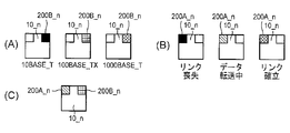
(1)上記実施形態のネットワーク装置1では、図1に示すように、LED200A_nおよびLED200B_nがポート10_nとは別個に設けられていたが、図6(A)に示すようにこれらを一体として設けても良い。図6(A)は本変形例のネットワーク装置1の正面図である。図6(A)に示すように、本変形例におけるポート10_nはLANケーブルが接続されるLANポートであり、凸型の開口を有している。ポート10_nの開口の右肩にはLED200B_nが設けられており、同左肩にはLED200A_nが設けられている。LED200A_nおよびLED200B_nは、緑色および橙色の2色の発光が可能な2色発光LEDであり、消灯、緑点滅、緑点灯、橙点滅、および橙点灯の5つの状態を取り得る。以下、本変形例では、これら5つの状態を図6(B)に示すハッチングにより区別する。
以上、この発明の各種の実施形態について説明したが、この発明には他にも実施形態が考えられる。
(1)上記実施形態のネットワーク装置1では、図1に示すように、LED200A_nおよびLED200B_nがポート10_nとは別個に設けられていたが、図6(A)に示すようにこれらを一体として設けても良い。図6(A)は本変形例のネットワーク装置1の正面図である。図6(A)に示すように、本変形例におけるポート10_nはLANケーブルが接続されるLANポートであり、凸型の開口を有している。ポート10_nの開口の右肩にはLED200B_nが設けられており、同左肩にはLED200A_nが設けられている。LED200A_nおよびLED200B_nは、緑色および橙色の2色の発光が可能な2色発光LEDであり、消灯、緑点滅、緑点灯、橙点滅、および橙点灯の5つの状態を取り得る。以下、本変形例では、これら5つの状態を図6(B)に示すハッチングにより区別する。
本変形例のネットワーク装置1における表示モード1は、各ポートの通信速度および通信状態(リンク喪失状態であるか、リンク確立状態であるか、データ転送中であるか)を表示するモードであり、表示モード2はループの発生の有無を表示する表示モードであり、表示モード3はポート10_nに割り当てられたVLANID(以下、VIDと略記)を表示する表示モードである。これら各表示モードにおける表示態様の具体例は以下の通りである。
表示モード1においては、LED200B_nを用いてポート10_nを介したデータ通信の通信速度が表示され、LED200A_nを用いてポート10_nを介したデータ通信の状態(リンクの確立の有無等)が表示される。例えば、制御部500は、図7(A)に示すように、ポート10_nを介したデータ通信の物理層が10BASE-T(すなわち、通信速度=10メガビット/秒)であればLED200B_nを消灯させ、100BASE-TX(通信速度=100メガビット/秒)であればLED200B_nを橙色で点灯させ、1000BASE-T(通信速度=1ギガビット/秒)であればLED200B_nを緑色で点灯させる。また、制御部500は、図7(B)に示すように、ポート10_nを介したデータ通信がリンク喪失状態であればLED200A_nを消灯させ、リンク確立状態であればLED200A_nを緑色で点灯させ、データ転送中であればLED200A_nを緑色で点滅させる。このため、ポート10_nを介したデータ通信の物理層が100BASE-TXであり、かつデータ転送中であれば、LED200A_nおよびLED200B_nの表示状態は図7(C)の様になる。
表示モード2においては、制御部500は、図8に示すように、ポート10_nについてループを検知しブロッキングを行った場合にはLED200A_nおよびLED200B_nを橙色で点滅させ、他のポートに関してループを検出したもののポート10_nに関してはループを検出しなかった場合には、LED200A_nおよびLED200B_nを橙色で点灯させる。また、制御部500は、ループを未検知の場合、またはポート10_nにLANケーブルの接続されていない場合にはLED200A_nおよびLED200B_nを消灯させる。
表示モード3においては、制御部500は、ポート10_nにVIDが設定されていない場合には図9(A)に示すように、LED200A_nおよびLED200B_nを消灯させ、ポート10_nにVIDが設定されている場合には、図9(B)~(I)の各表示パターンでポート10_nに設定されているVIDを表示する。より詳細に説明すると、図9(B)~(G)はネットワーク装置1において各ポートに割り当てられているVIDの若いものから6個を表示する表示パターン(図9(B)が最も若く、以下、図9(C)、図9(D)、図9(E)、図9(D)の順に若い)であり、図9(H)はそれ以外のVIDを示す表示パターンであり、図9(I)は複数のVIDが割り当てられていることを示す表示パターンである。
例えば、ポート10_1にはVIDとして100が、ポート10_2にはVIDとして101が、ポート10_3にはVIDとして102が、ポート10_4にはVIDとして103が、ポート10_5にはVIDとして104が、ポート10_6にはVIDとして105が、夫々設定されている場合には、制御部500は、LED200A_nおよびLED200B_n(n=1~6)を図10(A)のように点灯或いは消灯させる。また、ポート10_1にはVIDとして100と101が、ポート10_2にはVIDとして102が、ポート10_3にはVIDとして103が、ポート10_4にはVIDとして104と105が、ポート10_5にはVIDとして104が、ポート10_6にはVIDとして106が、それぞれ設定されている場合には、制御部500は、LED200A_nおよびLED200B_n(n=1~6)を図10(B)のように点灯或いは消灯させる。
(2)上記実施形態において、ネットワーク装置1の設定や状態に変化が生じる際にその変化前の設定や状態に関する情報をログとして不揮発性記憶部524に書き込んで保存し、スイッチ40に対する操作に応じて当該ログに応じた発光パターンでLED200A_nおよび200B_nを点灯させる処理を制御部500に実行させても良い。これにより、ネットワーク管理者は、過去に設定されていたVIDや通信状態等を現在のものと比較したり、ネットワーク装置1による給電状態の経時的な変化を評価したりすることが可能となる。また、上記実施形態では、ネットワーク装置1の設定に関する情報や当該ネットワーク装置1の状態に関する情報が当該ネットワーク装置1の記憶部520に記憶されており、同ネットワーク装置1の制御部500が記憶部520から読み出した(取得した)情報に応じてLED200_nの表示制御を行う場合について説明したが、ネットワーク装置1と通信可能な記憶装置に上記各情報を記憶させておき、制御部500には当該記憶装置から取得した情報に応じてLED200_nの表示制御を行わせても良い。
(3)上記実施形態では、LED200_nの発光パターンによりネットワーク装置1の設定や状態を示す各情報の表示が行われたが、ブザーや音楽を放音する放音手段を設け、ブザーを鳴らす回数や、音楽またはその音色の種類により表示モード1~3が示す各情報を報知してもよい。また、LED200_nの発光パターンによりネットワーク装置1の設定や状態を示す各情報の表示を行い、ネットワーク装置1の設定や状態に変化が生じたときに音による報知を行うようにしても良い。
(4)上記実施形態では、LED200_nに2色LEDを用いた。しかし、VIDの値の範囲がより広い場合には、3色以上の発光が可能なLEDを用いても良く、LED以外の発光素子を用いても良い。LED300_1および300_2についても多色発光可能な発光素子を用い、点灯、消灯の組み合わせの他に発光色の組み合わせを含む発光パターンにより表示モードを表示しても良い。また、上記実施形態ではスイッチングハブへの本発明の適用例を説明したが、本発明の適用対象となるネットワーク装置はスイッチングハブには限定されず、ルータであっても良い。
(5)上記実施形態では、表示モード3において、1つのポートに接続された機器への給電状態を表示する例について示した。しかし、複数のポートに接続された機器への給電状態を表示してもよい。この場合、LED200_1~200_4、LED200_5~200_10、・・・、LED200_n-3~200_nをそれぞれ1つの単位とするLEDの組をつくり、各LEDの組に各ポートに接続された機器への給電状態を表示させればよい。
(6)上記実施形態において、制御部500は、表示モード1~3以外の設定や状態に関する情報をLED200_nに表示させてもよい。例えば、ネットワーク装置1がQoS(Quality of Service)機能を有する場合には、制御部500はデータ通信時に使用される帯域幅をLED200_nに表示させてもよい。
(7)上記実施形態では、VLANおよびPoEの両技術に対応したネットワーク装置への本発明の適用例を説明したが、いずれか一方の技術にのみ対応したネットワーク装置に本発明を適用しても良い。例えば、VLANには対応しているものの、PoEには対応していないネットワーク装置に本発明を適用する場合にはそのネットワーク装置に給電制御プログラム524bを記憶させておく必要はない。また、PoEには対応しているものの、VLANには対応していないネットワーク装置に本発明を適用する場合にはそのネットワーク装置にVLAN管理テーブル524eを記憶させておく必要はない。つまり、図4(B)における給電制御プログラム524bとVLAN管理テーブル524eは本発明のネットワーク装置の必須構成要素ではなく、そのネットワーク装置の対応技術に応じて適宜省略可能な任意構成要素である。また、VLANとは異なる他のネットワーク技術に対応したネットワーク装置に本発明を適用することも勿論可能である。他のネットワーク技術としては、例えば、リンクアグリゲーション技術やVRRP(Virtual Router Redundancy Protocol:仮想ルータ冗長プロトコル)技術が挙げられる。
リンクアグリゲーションとは、LANケーブル等により直結されたネットワーク装置間において、複数の物理的なポートを一つの論理的なポートとして利用する技術であり、通信速度の向上および耐障害性の向上を実現するための技術である。リンクアグリゲーションにおける論理的なポートは、複数の物理的なポートで構成され、LAG(Link Aggregation Group:リンクアグリゲーショングループ)と呼ばれる。同一のLAGに属する物理的なポートには、同一のLAG番号が割り当てられる。リンクアグリゲーションに対応したネットワーク装置に本発明を適用することで、各ポートに割り当てられたLAG番号をLED200A_nおよび200B_nの発光パターンにより表示することが可能となる。具体的には、VLAN管理テーブル524eに代えて、ポート10_n(n=1~N)の各々を示す識別子(ポート番号)に対応付けて、当該識別子の示すポートに割り当てられたLAG番号を格納したLAG管理テーブルを不揮発性記憶部524に格納しておき、このLAG管理テーブルの格納内容に応じたLED200A_nおよびLED200B_nの点灯制御を制御部500に行わせるようにすれば良い。
VRRPとは、ルータの多重化を行うためのプロトコルである。VRRP技術は、ルータの障害発生時における通信サービスの停止を回避することを可能とする。より詳細に説明すると、VRRP技術では、複数のルータを一つのグループとして扱い、グループ内の各ルータに優先度を与える。通常時は優先度が高いルータ(マスタルータ)による通信が行われるが、障害が発生すると、同一グループ内の他のルータ(バックアップルータ)のうち優先度が高いものに自動的に処理が切り替わり、通信を継続することが可能となる。VRRPに対応したネットワーク装置に本発明を適用することで、当該ネットワーク装置に与えられた優先度をLED200A_nおよび200B_nの発光パターンにより表示することが可能となる。
(8)上記実施形態では、ネットワーク装置の設定や状態を示す各情報を表示するための表示手段として、1つのポートに対して複数個ずつ設けられた発光素子(いわゆるインジケータ)を用いたが、液晶ディスプレイ(またはディスプレイデバイス)を用いても良い。ネットワーク装置の中には小型の液晶ディスプレイを備えているものがあり、このようなネットワーク装置であれば、液晶ディスプレイの表示画面に、LED200A_nおよび200B_nの各々に相当する表示領域を設け、これら表示領域をポートに対して1つずつ設けられた表示手段として用い、各種情報を表示するための表示制御(例えば各表示領域の表示色の制御)を制御部500に行わせるようにすれば良い。要は、制御部と、各々通信ケーブルが接続される1または複数のポートと、ポート毎に設けられた表示手段と、制御部とを有するネットワーク装置の制御部に、自装置の設定または状態に関する情報を記憶する記憶装置から当該情報を取得し、当該情報に応じて各表示手段の表示制御を行わせることで、当該情報をネットワーク管理者に視覚的に把握させる態様であれば良い。
(9)上記実施形態では、本発明の特徴を顕著に示す表示制御プログラム524cが記憶部520に予め記憶されていた。しかし、表示制御プログラム524cをCD-ROM(Compact Disk-Read Only Memory)などのコンピュータ読み取り可能な記録媒体に書き込んで配布しても良く、また、インターネットなどの電気通信回線経由のダウンロードにより配布しても良い。このようにして配布される表示制御プログラム524cにしたがってネットワーク装置の制御部(すなわち、CPU等のコンピュータ)を作動させることで、当該ネットワーク装置を本発明のネットワーク装置として機能させることが可能になるからである。
本出願は、2015年5月21日付で出願された日本国特許出願である特願2015-103754に基づくものであり、その優先権を享受し、その内容はここに参照として取り込まれる。
1…ネットワーク装置、10_n…ポート、20,30…表示部、40…スイッチ、200A_n,200B_n,300_1,300_2…LED、500…制御部、510…通信I/F部、520…記憶部、530…ユーザI/F部、522…揮発性記憶部、522a…表示モード情報、524…不揮発性記憶部、524a…中継制御プログラム、524b…給電制御プログラム、524c…表示制御プログラム、524d…OSプログラム、524e…VLAN管理テーブル。
Claims (12)
- ネットワーク装置であって、
各々通信ケーブルが接続される1または複数のポートと、
前記ポート毎に設けられた表示手段と、
前記ネットワーク装置の設定または状態に関する情報を記憶する記憶装置から当該情報を取得し、当該情報に応じて前記各表示手段の表示制御を行う制御部と、
を有することを特徴とするネットワーク装置。 - 請求項1に記載のネットワーク装置であって、更に
前記各表示手段に表示させる情報の切り替え指示を入力させるための操作部を有し、
前記制御部は、前記操作部に対する操作により指示された情報に応じて前記各表示手段の表示制御を行うことを特徴とするネットワーク装置。 - 請求項2に記載のネットワーク装置であって、
前記制御部は、
前記ネットワーク装置の設定または状態に変化が発生したことを契機としてその変化前の設定または状態に関する情報のログを前記記憶装置に書き込み、
前記操作部に対する操作に応じて、前記ログの示す設定または状態に応じて前記各表示手段の表示制御を行う
ことを特徴とするネットワーク装置。 - 請求項3に記載のネットワーク装置であって、更に
放音部を備え、
前記制御部は、前記ネットワーク装置の設定または状態に変化が発生したことを前記放音部からの放音により報知する
ことを特徴とするネットワーク装置。 - 請求項1~4の何れか一項に記載のネットワーク装置であって、
前記ポート毎に設けられた表示手段の各々は、複数個の発光素子であり、前記制御部は、前記情報に応じて各発光素子の発光パターンを制御する
ことを特徴とするネットワーク装置。 - 請求項5に記載のネットワーク装置であって、
前記制御部は、ポートに関する情報を当該ポートに対応する複数個の発光素子の発光パターンにより表示制御することを特徴とするネットワーク装置。 - 請求項6に記載のネットワーク装置であって、
ポートに関する前記情報はVLANIDであることを特徴とするネットワーク装置。 - 請求項1に記載のネットワーク装置であって、
前記制御部は、前記記憶装置から取得した情報に応じて、前記複数のポートに対応する複数の表示手段を全体的に表示制御し、1つの設定または状態を示すことを特徴とするネットワーク装置。 - 請求項8に記載のネットワーク装置であって、
前記制御部は、前記複数の表示手段に対する全体的な表示制御により他の機器への給電状態を示すことを特徴とするネットワーク装置。 - 請求項6に記載のネットワーク装置であって、
前記1または複数のポートは、複数の物理的なポートを含み、
前記複数の物理的なポートをリンクアリゲーションにより同一のLAG番号を割り当てた1つの論理的なポートとして構成し、
前記制御部は、ポートに関する情報として前記LAG番号を当該ポートに対応する複数個の発光素子の発光パターンにより表示制御することを特徴とするネットワーク装置。 - 各々通信ケーブルが接続される1または複数のポートと、前記ポート毎に設けられた表示手段とを有するネットワーク装置に対する制御方法であって、
前記ネットワーク装置の設定または状態に関する情報を記憶する記憶装置から当該情報を取得し、当該情報に応じて前記各表示手段の表示制御を行う、
ことを特徴とする制御方法。 - ネットワーク装置であって、
各々通信ケーブルが接続される1または複数のポートと、
前記ポート毎に設けられたインジケータまたはディスプレイデバイスと、
前記ネットワーク装置の設定または状態に関する情報を記憶する記憶装置から当該情報を取得し、当該情報に応じて前記各インジケータまたはディスプレイデバイスの表示制御を行うコントローラと、
を有することを特徴とするネットワーク装置。
Priority Applications (1)
| Application Number | Priority Date | Filing Date | Title |
|---|---|---|---|
| CN201680029537.8A CN107615717A (zh) | 2015-05-21 | 2016-05-20 | 网络装置及控制方法 |
Applications Claiming Priority (2)
| Application Number | Priority Date | Filing Date | Title |
|---|---|---|---|
| JP2015-103754 | 2015-05-21 | ||
| JP2015103754A JP2016220064A (ja) | 2015-05-21 | 2015-05-21 | ネットワーク装置 |
Publications (1)
| Publication Number | Publication Date |
|---|---|
| WO2016186197A1 true WO2016186197A1 (ja) | 2016-11-24 |
Family
ID=57320364
Family Applications (1)
| Application Number | Title | Priority Date | Filing Date |
|---|---|---|---|
| PCT/JP2016/064990 Ceased WO2016186197A1 (ja) | 2015-05-21 | 2016-05-20 | ネットワーク装置及び制御方法 |
Country Status (3)
| Country | Link |
|---|---|
| JP (1) | JP2016220064A (ja) |
| CN (1) | CN107615717A (ja) |
| WO (1) | WO2016186197A1 (ja) |
Families Citing this family (2)
| Publication number | Priority date | Publication date | Assignee | Title |
|---|---|---|---|---|
| JP7528477B2 (ja) * | 2020-03-12 | 2024-08-06 | オムロン株式会社 | 情報処理装置、情報処理システム、通知方法および情報処理プログラム |
| TWI792879B (zh) * | 2022-01-21 | 2023-02-11 | 明泰科技股份有限公司 | 網路交換機 |
Citations (8)
| Publication number | Priority date | Publication date | Assignee | Title |
|---|---|---|---|---|
| JPH0964890A (ja) * | 1995-08-28 | 1997-03-07 | Matsushita Electric Works Ltd | ネットワーク集線装置 |
| JPH11191785A (ja) * | 1997-12-25 | 1999-07-13 | Hitachi Cable Ltd | スイッチングハブ |
| JP2001352334A (ja) * | 2000-06-07 | 2001-12-21 | Nec Fielding Ltd | バーチャルlan設定機能付ハブ、バーチャルlan設定方法 |
| JP2002261871A (ja) * | 2001-03-01 | 2002-09-13 | Allied Tereshisu Kk | ネットワーク監視装置、ネットワーク監視プログラム、ネットワーク監視方法、及びコンピュータネットワークシステム |
| JP2004032308A (ja) * | 2002-06-25 | 2004-01-29 | Toshiba Corp | ポート接続状態表示方法および通信装置および通信システム |
| JP2006050046A (ja) * | 2004-08-02 | 2006-02-16 | Oki Data Corp | 画像形成装置 |
| JP2007088809A (ja) * | 2005-09-22 | 2007-04-05 | Alaxala Networks Corp | PoE(PowerOverEthernet(登録商標))システム |
| JP2010517474A (ja) * | 2007-01-30 | 2010-05-20 | アルカテル−ルーセント ユーエスエー インコーポレーテッド | モバイルpcユーザへのメッセージ通知および送達のための方法および装置 |
Family Cites Families (9)
| Publication number | Priority date | Publication date | Assignee | Title |
|---|---|---|---|---|
| JP2719371B2 (ja) * | 1988-11-15 | 1998-02-25 | 松下電工株式会社 | 遠隔監視制御用端末器のアドレス設定器 |
| US5797767A (en) * | 1996-05-31 | 1998-08-25 | Berg Technology, Inc. | Indicator light modular jack |
| JP3710016B2 (ja) * | 1997-03-18 | 2005-10-26 | パイオニア株式会社 | データ転送装置 |
| EP1143574A1 (en) * | 2000-04-05 | 2001-10-10 | Molex Incorporated | Electrical connector assembly with light transmission module |
| CN1142538C (zh) * | 2000-04-11 | 2004-03-17 | 时志成 | 一种发光管组成的超大型显示屏幕控制方法及其装置 |
| CN2556867Y (zh) * | 2002-06-07 | 2003-06-18 | 余贵有 | 一种发光装置 |
| US20110106954A1 (en) * | 2008-09-26 | 2011-05-05 | Manjirnath Chatterjee | System and method for inductively pairing devices to share data or resources |
| CN101605412A (zh) * | 2009-07-17 | 2009-12-16 | 罗宏基 | Led通电发光电路 |
| CN103248844B (zh) * | 2013-04-25 | 2018-02-16 | 深圳Tcl新技术有限公司 | 面板按键控制电视机的方法及电视机 |
-
2015
- 2015-05-21 JP JP2015103754A patent/JP2016220064A/ja active Pending
-
2016
- 2016-05-20 CN CN201680029537.8A patent/CN107615717A/zh active Pending
- 2016-05-20 WO PCT/JP2016/064990 patent/WO2016186197A1/ja not_active Ceased
Patent Citations (8)
| Publication number | Priority date | Publication date | Assignee | Title |
|---|---|---|---|---|
| JPH0964890A (ja) * | 1995-08-28 | 1997-03-07 | Matsushita Electric Works Ltd | ネットワーク集線装置 |
| JPH11191785A (ja) * | 1997-12-25 | 1999-07-13 | Hitachi Cable Ltd | スイッチングハブ |
| JP2001352334A (ja) * | 2000-06-07 | 2001-12-21 | Nec Fielding Ltd | バーチャルlan設定機能付ハブ、バーチャルlan設定方法 |
| JP2002261871A (ja) * | 2001-03-01 | 2002-09-13 | Allied Tereshisu Kk | ネットワーク監視装置、ネットワーク監視プログラム、ネットワーク監視方法、及びコンピュータネットワークシステム |
| JP2004032308A (ja) * | 2002-06-25 | 2004-01-29 | Toshiba Corp | ポート接続状態表示方法および通信装置および通信システム |
| JP2006050046A (ja) * | 2004-08-02 | 2006-02-16 | Oki Data Corp | 画像形成装置 |
| JP2007088809A (ja) * | 2005-09-22 | 2007-04-05 | Alaxala Networks Corp | PoE(PowerOverEthernet(登録商標))システム |
| JP2010517474A (ja) * | 2007-01-30 | 2010-05-20 | アルカテル−ルーセント ユーエスエー インコーポレーテッド | モバイルpcユーザへのメッセージ通知および送達のための方法および装置 |
Also Published As
| Publication number | Publication date |
|---|---|
| CN107615717A (zh) | 2018-01-19 |
| JP2016220064A (ja) | 2016-12-22 |
Similar Documents
| Publication | Publication Date | Title |
|---|---|---|
| EP2430802B1 (en) | Port grouping for association with virtual interfaces | |
| CN101027873B (zh) | 网络管理的系统和方法 | |
| CN103026660B (zh) | 网络策略配置方法、管理设备以及网络管理中心设备 | |
| US7630299B2 (en) | Retention of a stack address during primary master failover | |
| US8248922B2 (en) | System and method for avoiding duplication of MAC addresses in a stack | |
| CN104753697B (zh) | 一种控制网络设备自动开局的方法、设备及系统 | |
| CN101536427B (zh) | 链路聚合 | |
| EP0926863A2 (en) | Automatic configuration of network links | |
| US20250355690A1 (en) | Method for electronic device virtualization and management | |
| CN102857416A (zh) | 一种实现虚拟网络的方法和虚拟网络 | |
| CN101557417A (zh) | 用于hba迁移的方法和装置 | |
| US20090049161A1 (en) | Server management program in network system | |
| JP5811196B2 (ja) | コンピュータシステム、及び仮想ネットワークの可視化方法 | |
| US11522754B2 (en) | Systems and methods for Zero-Touch Provisioning of a switch in intermediate distribution frames and main distribution frames | |
| JP2017041747A (ja) | 情報処理装置、情報処理装置の制御プログラム、制御方法及び情報処理システム | |
| CN110851186B (zh) | 网络设备重启的方法、装置、电子设备及可读存储介质 | |
| WO2016186197A1 (ja) | ネットワーク装置及び制御方法 | |
| US7206823B2 (en) | Computer system having a plurality of storage networks and method for setting information | |
| EP2785020A1 (en) | Method and system for distributing location-based addresses in a network | |
| JP3516905B2 (ja) | ホストコンピュータ、および、そのプログラムが記録された記録媒体、並びに、それを用いた制御システム | |
| US10319211B2 (en) | Visible indication of a port as configured to management functionality | |
| US20130242723A1 (en) | Data processing apparatus, data transceiver apparatus, and method for controlling data transmission and reception | |
| JP5282063B2 (ja) | ネットワーク経路表示方法、ケーブル抜去方法、ネットワーク経路表示システム | |
| JP2020113830A (ja) | 照明システム、ipアドレス設定装置およびipアドレス設定方法 | |
| US10608880B2 (en) | VLAN port signaling |
Legal Events
| Date | Code | Title | Description |
|---|---|---|---|
| 121 | Ep: the epo has been informed by wipo that ep was designated in this application |
Ref document number: 16796590 Country of ref document: EP Kind code of ref document: A1 |
|
| NENP | Non-entry into the national phase |
Ref country code: DE |
|
| 122 | Ep: pct application non-entry in european phase |
Ref document number: 16796590 Country of ref document: EP Kind code of ref document: A1 |