WO2016186079A1 - 複数の空気調和装置の管理装置 - Google Patents
複数の空気調和装置の管理装置 Download PDFInfo
- Publication number
- WO2016186079A1 WO2016186079A1 PCT/JP2016/064499 JP2016064499W WO2016186079A1 WO 2016186079 A1 WO2016186079 A1 WO 2016186079A1 JP 2016064499 W JP2016064499 W JP 2016064499W WO 2016186079 A1 WO2016186079 A1 WO 2016186079A1
- Authority
- WO
- WIPO (PCT)
- Prior art keywords
- information
- output level
- power consumption
- fluctuation range
- aggregator
- Prior art date
- Legal status (The legal status is an assumption and is not a legal conclusion. Google has not performed a legal analysis and makes no representation as to the accuracy of the status listed.)
- Ceased
Links
Images





Classifications
-
- F—MECHANICAL ENGINEERING; LIGHTING; HEATING; WEAPONS; BLASTING
- F24—HEATING; RANGES; VENTILATING
- F24F—AIR-CONDITIONING; AIR-HUMIDIFICATION; VENTILATION; USE OF AIR CURRENTS FOR SCREENING
- F24F11/00—Control or safety arrangements
- F24F11/89—Arrangement or mounting of control or safety devices
-
- H—ELECTRICITY
- H02—GENERATION; CONVERSION OR DISTRIBUTION OF ELECTRIC POWER
- H02J—ELECTRIC POWER NETWORKS; CIRCUIT ARRANGEMENTS OR SYSTEMS FOR SUPPLYING OR DISTRIBUTING ELECTRIC POWER; SYSTEMS FOR STORING ELECTRIC ENERGY
- H02J13/00—Circuit arrangements for providing remote monitoring or remote control of equipment in a power distribution network
-
- H—ELECTRICITY
- H02—GENERATION; CONVERSION OR DISTRIBUTION OF ELECTRIC POWER
- H02J—ELECTRIC POWER NETWORKS; CIRCUIT ARRANGEMENTS OR SYSTEMS FOR SUPPLYING OR DISTRIBUTING ELECTRIC POWER; SYSTEMS FOR STORING ELECTRIC ENERGY
- H02J3/00—Circuit arrangements for AC mains or AC distribution networks
-
- H—ELECTRICITY
- H02—GENERATION; CONVERSION OR DISTRIBUTION OF ELECTRIC POWER
- H02J—ELECTRIC POWER NETWORKS; CIRCUIT ARRANGEMENTS OR SYSTEMS FOR SUPPLYING OR DISTRIBUTING ELECTRIC POWER; SYSTEMS FOR STORING ELECTRIC ENERGY
- H02J3/00—Circuit arrangements for AC mains or AC distribution networks
- H02J3/12—Arrangements for adjusting voltage in AC networks by changing a characteristic of the network load
- H02J3/14—Arrangements for adjusting voltage in AC networks by changing a characteristic of the network load by switching loads on to, or off from, the networks, e.g. progressively balanced loading
-
- H—ELECTRICITY
- H02—GENERATION; CONVERSION OR DISTRIBUTION OF ELECTRIC POWER
- H02J—ELECTRIC POWER NETWORKS; CIRCUIT ARRANGEMENTS OR SYSTEMS FOR SUPPLYING OR DISTRIBUTING ELECTRIC POWER; SYSTEMS FOR STORING ELECTRIC ENERGY
- H02J2105/00—Networks for supplying or distributing electric power characterised by their spatial reach or by the load
- H02J2105/50—Networks for supplying or distributing electric power characterised by their spatial reach or by the load for selectively controlling the operation of the loads
- H02J2105/52—Networks for supplying or distributing electric power characterised by their spatial reach or by the load for selectively controlling the operation of the loads for limitation of the power consumption in the networks or in one section of the networks, e.g. load shedding or peak shaving
-
- Y—GENERAL TAGGING OF NEW TECHNOLOGICAL DEVELOPMENTS; GENERAL TAGGING OF CROSS-SECTIONAL TECHNOLOGIES SPANNING OVER SEVERAL SECTIONS OF THE IPC; TECHNICAL SUBJECTS COVERED BY FORMER USPC CROSS-REFERENCE ART COLLECTIONS [XRACs] AND DIGESTS
- Y02—TECHNOLOGIES OR APPLICATIONS FOR MITIGATION OR ADAPTATION AGAINST CLIMATE CHANGE
- Y02B—CLIMATE CHANGE MITIGATION TECHNOLOGIES RELATED TO BUILDINGS, e.g. HOUSING, HOUSE APPLIANCES OR RELATED END-USER APPLICATIONS
- Y02B70/00—Technologies for an efficient end-user side electric power management and consumption
- Y02B70/30—Systems integrating technologies related to power network operation and communication or information technologies for improving the carbon footprint of the management of residential or tertiary loads, i.e. smart grids as climate change mitigation technology in the buildings sector, including also the last stages of power distribution and the control, monitoring or operating management systems at local level
- Y02B70/3225—Demand response systems, e.g. load shedding, peak shaving
-
- Y—GENERAL TAGGING OF NEW TECHNOLOGICAL DEVELOPMENTS; GENERAL TAGGING OF CROSS-SECTIONAL TECHNOLOGIES SPANNING OVER SEVERAL SECTIONS OF THE IPC; TECHNICAL SUBJECTS COVERED BY FORMER USPC CROSS-REFERENCE ART COLLECTIONS [XRACs] AND DIGESTS
- Y04—INFORMATION OR COMMUNICATION TECHNOLOGIES HAVING AN IMPACT ON OTHER TECHNOLOGY AREAS
- Y04S—SYSTEMS INTEGRATING TECHNOLOGIES RELATED TO POWER NETWORK OPERATION, COMMUNICATION OR INFORMATION TECHNOLOGIES FOR IMPROVING THE ELECTRICAL POWER GENERATION, TRANSMISSION, DISTRIBUTION, MANAGEMENT OR USAGE, i.e. SMART GRIDS
- Y04S20/00—Management or operation of end-user stationary applications or the last stages of power distribution; Controlling, monitoring or operating thereof
- Y04S20/20—End-user application control systems
- Y04S20/222—Demand response systems, e.g. load shedding, peak shaving
Definitions
- the present invention relates to a management device for a plurality of air conditioners.
- a demand control request for adjusting power consumption is made from a main body on the power supply side.
- the management device When the management device accepts the adjustment request of the power consumption amount from the main body on the power supply side, for example, the customer who can accept the request among a plurality of customers managed by the management device and the power consumption that can be reduced By specifying the amount and having the consumer perform the reduction adjustment of the power consumption, it responds to the power consumption adjustment request from the main body on the power supply side. An incentive is given to the consumer who cooperated in adjusting the power consumption.
- the management device can determine the amount of power consumption by a plurality of consumers that it manages. It is required to make an accurate prediction.
- Patent Document 1 International Publication No. 2013-099323
- an error is obtained by comparing and the meteorological prediction in consideration of a fluctuation range corresponding to the error to perform an accurate prediction of power consumption.
- An object of the present invention has been made in view of the above-described points, and can improve the accuracy of prediction of power consumption, and can stably respond to power consumption adjustment requests from the main body on the power supply side. It is providing the management apparatus of a some air conditioning apparatus.
- the management apparatus of the some air conditioning apparatus which concerns on a 1st viewpoint is a management apparatus which performs management based on the adjustment request
- the information acquisition unit acquires past operation information about a plurality of air conditioners to be managed.
- the reference output level grasping unit obtains a reference output level that is a reference of the total output level for each predetermined period of the plurality of air conditioners to be managed, based on past operation information.
- the output level fluctuation range grasping unit is a range of output levels in which a predetermined ratio or more is concentrated with respect to the distribution of the total output level for each predetermined period of the plurality of air conditioners to be managed. Then, a range including the reference output level is obtained as the fluctuation range of the output level.
- the power consumption fluctuation range prediction unit obtains a predicted value of the fluctuation range of the power consumption amount of the plurality of air conditioners to be managed based on the fluctuation range of the output level.
- the output level is not particularly limited, but is a value where the power consumption increases as the value increases and the power consumption decreases as the value decreases.
- the output level includes the output rate relative to the rated power consumption and the output rate relative to the rated capacity.
- the management device itself of the plurality of air conditioners has a storage unit that stores past operation information about the plurality of air conditioners to be managed, and the information acquisition unit receives a plurality of management targets from the storage unit. You may acquire by reading the past operation information about other air conditioners.
- the management apparatus of a some air conditioning apparatus does not have the memory
- the operation information is stored in a storage device that is another device (for example, a cloud information terminal that is communicably connected in a network), and the information acquisition unit can communicate with a plurality of air conditioner management devices. You may acquire the past operation information about the several air conditioning apparatus of management object from the connected memory
- the “reference output level” is not particularly limited, and may be, for example, an average value of a total output level for each predetermined period of a plurality of air conditioners to be managed, or a median value. However, it may be a mode value.
- the “output level fluctuation range” is not particularly limited, for example, as a range of plus or minus a predetermined% of the average value of the total (each sample) output level for each predetermined period of a plurality of air conditioners to be managed.
- the fluctuation range may be determined, the fluctuation range may be set as a range including the average value and including the predetermined percentage of the whole (predetermined percentage of all samples), or the predetermined range of a plurality of air conditioners to be managed
- the fluctuation range may be determined as a range of the plus / minus of the mode value of the output level of the total (each sample) for each period, or the entire range including the mode value (predetermined percent of all samples)
- the range of fluctuation may be determined as a range including.
- the management apparatus of the some air conditioning apparatus respond
- the management apparatus for a plurality of air conditioners according to the second aspect is a management apparatus for a plurality of air conditioners according to the first aspect, and further includes an output level fluctuation range correction unit.
- the output level fluctuation range correction unit corrects the output level fluctuation range based on at least one of weather forecast, air conditioner operation content schedule information, and air conditioner maintenance information.
- the operation content schedule information of the air conditioner is not particularly limited, for example, when an air conditioner having a control mode of a normal operation control mode and an energy saving operation control mode exists as a management target, Information indicating the scheduled date and time when the energy saving operation control mode is performed instead of the normal operation control mode is included.
- information indicating the set temperature schedule is included.
- the management apparatus of several air conditioning apparatus acquires a weather forecast, the operation content schedule information of an air conditioning apparatus, and the maintenance information of an air conditioning apparatus, it communicates from each managed air conditioning apparatus by communication. It may be obtained directly, or may be obtained by communication from another device communicably connected in the network.
- the output level fluctuation range is determined so that the output level fluctuation range correction unit includes at least the weather forecast, the operation content schedule information of the air conditioner, and the maintenance information of the air conditioner. Correct based on either.
- the power consumption fluctuation range prediction unit obtains a predicted value of the fluctuation range of the power consumption amount of the plurality of air conditioners to be managed based on the corrected fluctuation range of the output level. For this reason, it is possible to obtain a more accurate predicted value of the fluctuation range of the power consumption by using a more accurate fluctuation range of the output level.
- the management apparatus for a plurality of air conditioners according to the third aspect is a management apparatus for a plurality of air conditioners according to the first aspect or the second aspect, and further includes an operating number predicting unit.
- the operation number predicting unit is a predicted value of the operation number of the plurality of air conditioners to be managed based on the unit history information indicating the number of operation for each predetermined period in the past among the plurality of air conditioners to be managed. Ask for.
- the power consumption fluctuation range prediction unit obtains a predicted value of the fluctuation range of the power consumption of the plurality of air conditioners to be managed based on the fluctuation range of the output level and the predicted value of the number of operating units.
- the predicted value of the number of operating units obtained based on the unit number history information is not particularly limited, and may be, for example, an average value of operating units for each predetermined period in the past or a median value. However, it may be a mode value.
- the power consumption fluctuation range prediction unit takes into account the predicted value of the number of operating units, so that the predicted value of the fluctuation range of power consumption increases when the predicted value of the operating number is relatively large. In this way, when the predicted value of the number of operating units is relatively small, the predicted value of the fluctuation range of the power consumption can be obtained so that the predicted value of the fluctuation range of the power consumption becomes small.
- the power consumption fluctuation range prediction unit calculates not only the fluctuation range of the output level but also the predicted value of the fluctuation range of the power consumption amount of the plurality of air conditioners to be managed. This further reflects the predicted value of the number of units in operation. For this reason, it is possible to take into account the possibility that the number of operating units will increase or the number of operating units will decrease, and it is possible to increase the possibility of approaching the actual operating state for the predicted value of the fluctuation range of the power consumption. .
- the management apparatus for a plurality of air conditioners according to the fourth aspect is a management apparatus for a plurality of air conditioners according to the third aspect, and further includes an operating number correction unit.
- the operating number correction unit corrects the predicted value of the operating number based on the use schedule information of the air conditioner.
- the use schedule information of the air conditioner is not particularly limited, and includes a schedule for stopping the operation of the air conditioner, schedule information of the user of the air conditioner, and the like.
- the management devices of the plurality of air conditioners may be directly obtained from each air conditioner to be managed by communication, or connected to be communicable in a network. You may make it acquire by communication from the other apparatus made.
- the operating number correction unit corrects the predicted number of operating units based on the use schedule information of the air conditioning units.
- the power consumption fluctuation range predicting unit obtains a predicted value of the fluctuation range of the power consumption amount of the plurality of air conditioners to be managed based on the fluctuation range of the output level and the corrected predicted number of operating units. For this reason, it is possible to obtain a more accurate predicted value of the fluctuation range of the power consumption by using a more accurate predicted value of the number of operating units.
- the management apparatus of the some air conditioning apparatus which concerns on a 5th viewpoint is a management apparatus of the several air conditioning apparatus which concerns on either of the 1st viewpoint to the 4th viewpoint, Comprising: Past operation information is a past predetermined period. The information of the output ratio with respect to the rated power consumption of the some air conditioning apparatus of the management object in is included.
- the value of the output ratio with respect to the rated power consumption is obtained as 10 values for the past 10 days, and the total is divided by 10 to output the day. Even if the average value of the ratio is calculated and the fluctuation range of the output level is determined as a range including a predetermined percentage (for example, six samples in the case of 60%) of all samples (10 samples) including the average value, Good.
- a predetermined percentage for example, six samples in the case of 60%
- the management apparatus for a plurality of air conditioners by using a power amount that can be responded with high accuracy with respect to a power consumption adjustment request, it is stable to a power consumption adjustment request from an entity on the power supply side. Can be met.
- the management apparatus for a plurality of air conditioners it is possible to obtain a more accurate predicted value of the fluctuation range of the power consumption by using the more accurate fluctuation range of the output level.
- the management apparatus for a plurality of air conditioners according to the third aspect, it is possible to increase the possibility of approaching the actual driving situation with respect to the predicted value of the fluctuation range of the power consumption.
- the management apparatus for a plurality of air conditioners it is possible to obtain a more accurate predicted value of the fluctuation range of power consumption by using a more accurate predicted value of the number of operating units.
- the management apparatus for a plurality of air conditioners it is possible to improve the accuracy of prediction of the fluctuation range of the power consumption using the information of the output ratio with respect to the rated power consumption.
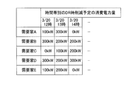
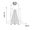
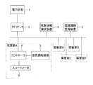
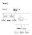
- FIG. 1 is a schematic configuration diagram of an entire information processing system including an aggregator according to an embodiment of the present invention. It is a schematic block diagram of an air conditioning apparatus. It is a block diagram containing the controller in the consumer A, an air conditioning apparatus, and a smart meter. It is a block diagram of an aggregator. It is a figure which shows the example of DR response schedule of each consumer. It is a figure which shows the example of the reduction amount of power consumption obtained from DR response schedule of each consumer. It is a flowchart of a process of an aggregator. It is a figure which shows the fluctuation range of a reference
- FIG. 1 shows a schematic configuration diagram of the entire information processing system.
- the electric power company 1 is a company that supplies generated electric power to each consumer.
- the aggregator 3 is connected so as to be able to communicate with the controllers 4 possessed by the plurality of consumers A to E, respectively, and operates the air conditioners 5 possessed by the plurality of consumers A to E. Perform management.
- the aggregator 3 is also communicably connected to the electric power company 1 and receives an instruction to adjust the power consumption amount from the electric power company 1 when power is tight. Although omitted here, there are other aggregators and large-scale properties that receive a power consumption adjustment instruction from the electric power company 1, and the aggregator 3 of this embodiment is more reliable than these. By responding to the adjustment request with high efficiency, it aims to be able to preferentially process the adjustment request for the power consumption amount from the electric power company 1.
- Each customer A to E is an object that is comprehensively managed by the aggregator 3, and has a controller 4, an air conditioner 5, and a smart meter 6, respectively. There are usually countless more consumers.
- Each controller 4 included in each consumer A to E is connected to an air conditioner 5 and a smart meter 6 included in the corresponding consumer, and is also connected to the aggregator 3.
- the air conditioner 5 possessed by each of the consumers A to E is driven by consuming electric power supplied from the electric power company 1 and harmonizes the air in the target space.
- the meteorological information providing device 9 is connected to the aggregator 3 so as to be communicable, and provides weather information of each place to the aggregator by communication. Specifically, the weather information providing device 9 of the present embodiment provides information on the predicted temperature for each time zone for each region.
- the power company 1 issues a demand control request (power consumption adjustment request) for requesting adjustment of the power consumption.
- the aggregator 3 since the aggregator 3 includes a plurality of consumers A to E as a management target instead of a single one, the range in which the power consumption can be adjusted is larger than that in the case of managing a single consumer. It is possible to do. Then, when the aggregator 3 receives the power consumption adjustment request transmitted by the power company 1, for example, in the case of a power consumption reduction request, the aggregator 3 cooperates in reduction among the consumers A to E to be managed. Reduce the amount of power consumed by consumers who can. Here, incentives are given to consumers who have obtained cooperation by reducing the price of electricity or giving money.
- Each of the consumers A to E managed by the aggregator 3 is not obligated to respond to the power consumption adjustment request transmitted by the electric power company 1, is an optional free participation type, and requires incentives. Will participate.
- each consumer can cancel a request for adjustment of power consumption during the time period for which participation has been applied once, in which case it will receive a predetermined penalty (such as an increase in electricity bill). Become.
- the aggregator 3 receives the adjustment request for the power consumption amount from the power company 1 in advance so that the adjustment request processing can be completed within the adjustable range by the consumer managed by the self as much as possible. It is obtained by having each customer report the schedule information on whether or not to respond to the power consumption adjustment request (how much, if so). However, each consumer does not necessarily operate the air conditioner 5 as scheduled in advance, and even when a power consumption adjustment request from the power company 1 is transmitted, There is a possibility that the adjustment of the power consumption amount as planned cannot be performed due to a change in schedule or a change in weather.
- the aggregator 3 not only the schedule information obtained from each consumer in advance but also the information on the variable factors that may occur in the future, the aggregator 3 can be adjusted with high power consumption. It is desirable to obtain (report reduction amount) and report it to the electric power company 1 in advance. That is, as the aggregator 3, not only the adjustable amount obtained from the schedule information reported from each customer in advance, but also the power consumption (declared reduction amount) obtained by subtracting the future variable factor from the adjustable amount. ) Is specified as information for reporting to the electric power company 1.
- the report reduction amount that the aggregator 3 can report to the electric power company 1 becomes small, and as a result, the aggregator The amount of incentive obtained by each consumer managed by 3 in response to a request for adjusting the amount of power consumption becomes small.
- the aggregator 3 can obtain the fluctuation factors that may occur in the future as accurately as possible (avoid increasing the fluctuation factors unnecessarily) and can be adjusted based on the schedule information reported from each customer in advance. It is desirable to have as many incentives as possible for the customers who manage it as much as possible by specifying the report reduction amount that keeps the amount subtracted from the amount small.
- the incentive is not particularly limited.
- the incentive may be granted to each customer from the electric power company 1 or from the electric power company 1 to the aggregator 3 according to the contents of the contract.
- the aggregator 3 may grant the incentive granted to each customer managed by itself.
- each consumer has one air conditioner 5 having the same operating capacity (horsepower), and there are 1 adjustment requests for power consumption and various schedules.
- Horsepower operating capacity
- FIG. 2 shows a schematic configuration diagram of the air conditioner 5 that each of the consumers A to E has.
- FIG. 3 shows a block diagram of the controller 4, the air conditioner 5, and the smart meter 6 in the customer A.
- the air conditioner 5 includes a refrigerant circuit 20 and various temperature sensors 28a, 28b, and 29.
- the refrigerant circuit 20 includes a compressor 21 capable of frequency control, a four-way switching valve 22 capable of switching between a cooling operation and a heating operation by switching the connection state, an outdoor heat exchanger 23, and an outdoor fan capable of adjusting the air volume. 24, an expansion valve 25 capable of adjusting the valve opening degree, an indoor heat exchanger 26, and an indoor fan 27 capable of adjusting the air volume, which are connected in order.
- the compressor 21, the four-way switching valve 22, the outdoor fan 24, the expansion valve 25, and the indoor fan 27 are connected to the controller 4, and various controls are performed by the control unit 41 of the controller 4.
- the compressor 21 can adjust the degree to which the refrigerant is compressed by controlling the drive frequency according to an instruction from the control unit 41.
- the four-way switching valve 22 can switch between a cooling operation and a heating operation by switching the connection state according to an instruction from the control unit 41.
- Each of the outdoor fan 24 and the indoor fan 27 can adjust the air volume according to an instruction from the control unit 41.
- the expansion valve 25 can adjust the degree of decompression of the refrigerant by adjusting the opening degree of the valve through which the refrigerant passes according to an instruction from the control unit 41.
- the refrigerant circuit 20 includes the four-way switching valve 22, it can be switched between the cooling operation and the heating operation.
- the refrigerant discharged from the compressor 21 exchanges heat between the outside air sent from the outdoor fan 24 and the refrigerant via the four-way switching valve 22, thereby serving as a refrigerant condenser. It is sent to a functioning outdoor heat exchanger 23.
- the refrigerant condensed in the outdoor heat exchanger 23 is depressurized in the expansion valve 25, and then heat exchange is performed between the air in the air-conditioning target space sent from the indoor fan 27 and the refrigerant, thereby evaporating the refrigerant.
- It is sent to the indoor heat exchanger 26 that functions as a heat exchanger.
- the refrigerant evaporated in the indoor heat exchanger 26 is sent to the suction side of the compressor 21 through the four-way switching valve 22. By such an operation, the air-conditioning target space is cooled.
- the refrigerant discharged from the compressor 21 undergoes heat exchange between the air in the air-conditioning target space sent from the indoor fan 27 via the four-way switching valve 22 and the refrigerant. It is sent to the indoor heat exchanger 26 that functions as a condenser.
- the refrigerant condensed in the indoor heat exchanger 26 is decompressed in the expansion valve 25 and then functions as a refrigerant evaporator by performing heat exchange between the outside air sent from the outdoor fan 24 and the refrigerant. It is sent to the outdoor heat exchanger 23.
- the refrigerant evaporated in the outdoor heat exchanger 23 is sent to the suction side of the compressor 21 through the four-way switching valve 22.
- Various temperature sensors include an outdoor temperature sensor 28a, an outdoor heat exchange temperature sensor 28b, and an indoor temperature sensor 29.
- the outdoor temperature sensor 28a is provided on the upstream side of the outdoor heat exchanger 23 in the air flow direction of the outdoor fan 24, and detects the outdoor air temperature.
- the outdoor heat exchanger temperature sensor 28 b is provided at an intermediate position of the outdoor heat exchanger 23 and detects the temperature of the refrigerant passing through the intermediate position of the outdoor heat exchanger 23.
- the indoor temperature sensor 29 is provided on the upstream side of the indoor heat exchanger 26 in the direction of air flow by the indoor fan 27, and detects the temperature of the room that is the air-conditioning target space.
- These various temperature sensors are all connected to the controller 4 so that the control unit 41 of the controller 4 can grasp each detected value.
- the control unit 41 performs various controls of the compressor 21, the outdoor fan 24, the expansion valve 25, and the indoor fan 27 based on the detection values of various temperature sensors, and switches the connection state of the four-way switching valve 22.
- the drive level of the compressor 21 increases according to the degree of not being satisfied. Then, more power is consumed and the air-conditioning target space is quickly cooled.
- the air conditioner 5 has a normal operation control mode and an energy saving operation control mode as control modes.
- This energy-saving operation control mode is not particularly limited, but is a control mode that takes a longer time than the normal operation control mode when the air-conditioning target space is set to a set temperature, and a control mode that consumes less power per unit time. It is.
- the smart meter 6 is connected to the controller 4 and transmits information on the measured power consumption to the controller 4.
- the controller 4 includes a control unit 41, an input unit 42, an output unit 43, a storage unit 44, and the like. ing. The same applies to the controllers 4 included in the consumers B to E.
- the control unit 41 adjusts the power consumption of the air conditioner 5 of the consumer (the consumer A here) when responding to the power consumption adjustment request from the power company 1 (details will be described later). ), Information related to operation from the air conditioner 5 and information from the smart meter 6 are stored in the storage unit 44, information received from the input unit 42, output processing to the output unit 43, and the like. Although not particularly limited, for example, the control unit 41 can be configured by a CPU.
- the output unit 43 is not particularly limited, but may be a liquid crystal display panel, for example. Information processed by the control unit 41 is displayed on the output unit 43.
- the input unit 42 is for a user or the like to input information to the controller 4, and is not particularly limited.
- a liquid crystal display panel of the output unit 43 is a touch panel.
- the input unit 42 receives input of various information described later from the user.
- the storage unit 44 is not particularly limited, but can be constituted by, for example, a ROM, a RAM, a hard disk, or the like.
- the storage unit 44 stores various information such as DR schedule information 44a, schedule information 44b, output level history information 44c, operation history information 44d, area information 44e, set temperature 44f, DR control information 44g, and the control unit 41.
- Various programs to be executed are stored.
- the DR schedule information 44a includes date and time information according to a request for adjustment of power consumption from the power company 1, and information indicating the power consumption scheduled to be reduced in the corresponding time zone when responding.
- the DR schedule information 44a is stored or updated when an input is received from a user (for example, a customer) via the input unit 42.
- a user for example, a customer
- each user can input the schedule from the input unit 42 and report the schedule to the aggregator 3 so that the DR schedule information 44a for one week in the future is always stored.
- the DR schedule information 44a corresponds to, for example, data for one customer in FIG. In this case, DR is an abbreviation for demand response.
- the schedule information 44b is information indicating a use schedule of the air conditioner 5 by the user, and includes, for example, information on a scheduled date and time when the air conditioner 5 is operated and a scheduled date and time when the air conditioner 5 is not operated. Further, the schedule information 44b includes information indicating a scheduled date and time when the energy saving operation control mode is performed instead of the normal operation control mode. Further, the schedule information 44b includes information indicating a set temperature schedule. The schedule information 44b is stored or updated when an input is received from the user via the input unit.
- the output level history information 44c is information of the past air conditioner 5 regarding the output ratio (output level) with respect to the rated power consumption determined in advance for the air conditioner 5. In this embodiment, average information for each hour of the output ratio with respect to the past rated power consumption is stored.
- the control unit 41 can grasp the output ratio (%) with respect to the rated power consumption from the value measured by the smart meter 6. Specifically, for example, when 100% is operated at the rated power consumption for 1 hour, 0% is not operated for 1 hour, and at the rated power consumption for 30 minutes within 1 hour.
- the output ratio (output level) is specified with 50% being the case where the operation has been stopped and the remaining 30 minutes have been stopped.
- the operation history information 44d includes information on various air conditioners 5. Specifically, it is information indicating a history of power consumption in the air conditioner 5 (a history of measured values by the smart meter 6), and includes information indicating the power consumption of the air conditioner 5 for each date and time. Moreover, the information of the outdoor temperature of the air conditioning apparatus 5 is also included.
- the area information 44e is information indicating an area where the air conditioner 5 directly connected to the controller 4 is located, and is stored by receiving an input from the user via the input unit 42. For example, the information which shows the address of the said air conditioning apparatus 5 may be sufficient.
- the set temperature 44 f is information on a set temperature that is a target when the air conditioner 5 is operated, and is stored or updated when an input is received from the user via the input unit 42.
- the DR control information 44g is information indicating the control content of the air conditioner 5 to be performed when there is an adjustment request of the power consumption amount from the electric power company 1 and the adjustment request is satisfied. For example, when reducing specific power consumption during cooling operation, increasing the set temperature in stages according to the power consumption to be reduced, or when reducing specific power consumption during heating operation. In addition, there is information for performing control that lowers the set temperature step by step according to the amount of power consumption to be reduced, control for stopping operation when a specific power consumption cannot be reduced by changing the set temperature, etc. Stored.
- the control unit 41 of the customer's controller 4 that has received the power consumption reduction instruction from the aggregator 3 step by step until the reduction of the power consumption scheduled for reduction previously set in the DR schedule information 44a can be realized.
- a process for changing the set temperature is performed, and when it is not possible to realize a reduction in the amount of power consumption scheduled to be reduced by only changing the set temperature, a process for stopping the operation is performed.
- FIG. 4 shows a block diagram of the aggregator 3.
- the aggregator 3 includes a control unit 31, an input unit 32, an output unit 33, a storage unit 34, and the like.
- the control unit 31 performs various processes for managing and adjusting the power consumption of the consumers A to E to be managed so as to respond to the power consumption adjustment request from the power company 1 (details will be described later). In addition, a process for collecting the status of each air conditioner 5 in each consumer A to E, a process for creating information based on the collected information, a process for storing the created information in the storage unit 34, and an input Processing of information received from the unit 32, output processing for the output unit 33, and the like are performed. Although not particularly limited, for example, the control unit 31 can be configured by a CPU.
- the output unit 33 is not particularly limited, but may be a liquid crystal display panel, for example. Information output by the control unit 31 is displayed on the output unit 33.
- the input unit 32 is used by the administrator of the aggregator 3 to input information to the aggregator 3, and is not particularly limited.
- a liquid crystal display panel of the output unit 33 may be a touch panel.
- the input unit 32 receives input of various information from the administrator of the aggregator 3.
- the storage unit 34 is not particularly limited, but can be configured by, for example, a ROM, a RAM, a hard disk, or the like.
- each customer DR schedule information 34a, each customer schedule information 34b, each customer output level history information 34c, each customer operation history information 34d, each customer area information 34e, each customer DR A variety of information such as the grade information 34f, the DR schedule summary information 34g, the output level summary information 34h, the number-of-operations information 34i, various programs to be executed by the control unit 31, and the like are stored.
- information that is updated by each customer is acquired in the storage unit 34 by the control unit 31 through communication as needed, and is rewritten with new information.
- Information creation and processing based on it is performed at any time.
- Each customer DR schedule information 34a is information that summarizes the DR schedule information 44a of all the customers A to E.
- Each customer DR schedule information 34a is created by the control unit 31 periodically acquiring and collecting the DR schedule information 44a of all the customers A to E through communication, and is stored in the storage unit 34. Yes.
- each customer DR schedule information 34a is information indicating the amount of power consumption scheduled to be reduced by each customer, as shown in FIG.
- Each customer schedule information 34b is information in which schedule information 44b of all the customers A to E is collected.
- Each customer schedule information 34b is created by the control unit 31 periodically acquiring and collecting schedule information 44b of all the customers A to E through communication, and is stored in the storage unit 34.
- Each customer output level history information 34c is information that summarizes the output level history information 44c of all the customers A to E.
- Each customer output level history information 34c is created by the control unit 31 periodically acquiring and collecting the output level history information 44c of all the consumers A to E through communication, and is stored in the storage unit 34. Has been.
- Each customer operation history information 34d is information that summarizes the operation history information 44d of all the customers A to E.
- Each of the customer operation history information 34d is created by the control unit 31 periodically acquiring and collecting the operation history information 44d of all the customers A to E through communication, and is stored in the storage unit 34. Yes.
- Each customer area information 34e is information that summarizes the area information 44e of all the consumers A to E.
- Each customer area information 34e is created by the control unit 31 obtaining and collecting the area information 44e of all the consumers A to E through communication, and is stored in the storage unit 34.
- Each customer DR performance information 34f is information indicating response results to requests for adjustment of past power consumption in each of the consumers A to E. Specifically, for each customer, when a power consumption adjustment request is actually transmitted from the power company 1 in the time zone indicated in the DR schedule information 44a that the customer has reported, This is information indicating whether or not the power consumption has been reduced. Although not particularly limited, for example, it may be a ratio of time during which power consumption can be reduced as planned (for example, when three requests for adjustment of power consumption for one hour are made five times, Can be reduced to 60% if the planned reduction is achieved.)
- the DR schedule summary information 34g is information that the control unit 31 creates based on each customer DR schedule information 34a. Specifically, as shown in FIG. 6, the total amount of power consumption scheduled for reduction (scheduled amount of reduction) reported from each customer ascertained from each customer DR schedule information 34 a is obtained for each date and time. Information obtained. Thereby, it is possible to grasp the planned amount of future power consumption reduction based on the reports of each customer managed by the aggregator 3.
- the output level summary information 34h is information that the control unit 31 creates based on each customer output level history information 34c. Specifically, the output level summary information 34h is information on the past output levels of the air conditioners 5 of the respective consumers A to E (information having an output level other than 0: operation was performed). Information), and the output level is associated with the corresponding date and time information. The control unit 31 performs the extraction of information here. Thereby, it becomes possible to grasp the output level when the operation is performed for the past air conditioners 5 of the consumers A to E in association with the date and time information.
- the number-of-operations information 34i is information that the control unit 31 creates based on each customer operation history information 34d. Specifically, this is information indicating, for each date and time, the total number of operating air conditioners 5 of the customers managed by the aggregator 3 at a past date and time (for one hour in the present embodiment).
- the control unit 31 determines whether or not the air conditioner 5 has been driven in a certain past time zone based on each customer operation history information 34d.
- the control unit 31 has a time during which the air conditioner 5 is driven during the one hour (power consumption is consumed by the smart meter 6 during the one hour. Is measured), it is determined that the operation has been performed, and it is counted that there has been one operation. In addition, you may make it count as having drive
- the control unit 31 of the aggregator 3 performs the aggregator before a power consumption adjustment request is transmitted from the power company 1 in the future (in advance).
- a process of specifying “declared reduction amount” of power consumption that can be accepted as 3 for each future date and time (for example, for one week) is performed.
- information on “declared reduction amount” of the specified power consumption is reported to the power company 1 in advance (information is transmitted to the power company 1 by communication).
- FIG. 7 shows the processing flow of the aggregator 3.
- step S10 the control unit 31 of the aggregator 3 uses the output level summary information 34h stored in the storage unit 34 for each future date and time, and uses the output level average (reference output level OS) and the distribution range (output). Level fluctuation range OL to OH) is obtained.
- control unit 31 is information of a past predetermined period (in the present embodiment, up to 10 days before) going back from the future date and time to be obtained in the output level summary information 34h, and the future date and time to be obtained.
- the reference output level OS and the output level fluctuation range OL to OH are obtained using only the information of the time zone corresponding to the time zone, and this processing is performed for each future date and time. As a result, it is possible to grasp the recent output trends of the entire air conditioner 5 of each consumer A to E managed by the aggregator 3.
- the reference output level OS is the information about the time zone corresponding to the future date and time among the information for the past predetermined period dating from the future date and time (for example, from 12:00 to 13:00 on March 20).
- Information on all the output levels of the air conditioners 5 of the respective consumers A to E (information on the air conditioners 5 of the respective consumers A to E from March 10 to 19 (the existing amount)) It is obtained by dividing the total of information from 12:00 to 13:00 on each day by the number of the information. This processing is performed for each future date and time (for example, it is also performed at 13:00 to 14:00 on March 20, and 14:00 to 15:00).
- the output level fluctuation ranges OL to OH are, specifically, the future date and time of the information during the past predetermined period dating from the future date and time (for example, from 12:00 to 13:00 on March 20).
- Information on all output levels of the air conditioner 5 of each consumer A to E for the corresponding time zone information on March 10 to 19 of the air conditioner 5 of each consumer A to E (existing As shown in FIG. 8, the distribution of occurrence frequency by output level is obtained as a predetermined width with respect to the reference output level OS.
- the upper limit OH of the output level fluctuation range OL to OH is for a plurality of information exceeding the reference output level OS, and in order from the smallest one to the future date and time among the information for the past predetermined period.
- a predetermined percentage of the total number of information for the corresponding time zone for example, 30% in this embodiment
- the output level of the information counted last is set to the fluctuation range of the output level. Obtained as the upper limit OH.
- the lower limit OL of the output level fluctuation range OL to OH is a time corresponding to the future date and time among the information in the past predetermined period in order from the largest for a plurality of pieces of information below the reference output level OS.
- the output level of the information that is finally counted when counting a predetermined percentage of the total number of information about the band (for example, 30% in this embodiment) is obtained as the lower limit OL of the fluctuation range of the output level. .
- the information included in the output level summary information 34h and the history information of the output level of the specific air conditioner 5 of a specific consumer at a specific date and time is counted as one piece of information. This processing is performed for each future date and time (for example, it is also performed at 13:00 to 14:00 on March 20, and 14:00 to 15:00).
- step S11 the control unit 31 of the aggregator 3 corrects the reference output level OS and the output level fluctuation range OL to OH obtained in step S10 based on weather information.
- the control unit 31 provides information on the predicted temperature for each region of the air conditioners 5 of the consumers A to E managed by the aggregator 3 with the weather information providing device 9.
- the average predicted temperature is obtained by summing up the temperatures of the predicted temperatures for each region and dividing by the number of information on the predicted temperatures.
- zone during the past predetermined period is calculated
- the air conditioning load increases or decreases, and according to the determination result, as shown in FIG.
- the obtained reference output level OS and output level fluctuation range OL to OH are corrected.
- the air conditioning load increases as the average expected temperature is higher than the average past temperature, and correction is performed to increase the reference output level OS and the output level fluctuation range OL to OH. Do.
- control part 31 grasps
- control part 31 grasps
- step S12 the control unit 31 of the aggregator 3 uses the operation number information 34i stored in the storage unit 34 for each future date and time, and uses the average operation number (reference operation number NS) and the distribution range (operation number). Fluctuation range NL to NH).
- control unit 31 is information of a past predetermined period (minutes up to 10 days in the present embodiment) that goes back from the future date and time to be obtained in the operating unit information 34i, and the future date and time to be obtained.
- the reference operation number NS and the fluctuation range NL to NH of the operation number are obtained, and this processing is performed for each future date and time.
- the reference operation number NS is calculated for each day in the time zone corresponding to the future date and time during the past predetermined period dating from the future date and time (for example, from 12:00 to 13:00 on March 20).
- Information on the number of operating air conditioners 5 of each consumer A to E (information on the air conditioners 5 of each customer A to E from March 10 to 19 (existing) on each day (Total number of operating vehicles from 12:00 to 13:00) (total number of operating vehicles) is divided by the number of days in each day. This processing is performed for each future date and time (for example, it is also performed at 13:00 to 14:00 on March 20, and 14:00 to 15:00).
- the fluctuation ranges NL to NH of the number of operating units are specifically the time corresponding to the future date and time during the past predetermined period dating from the future date and time (for example, from 12:00 to 13:00 on March 20).
- Information on the number of operating air conditioners 5 of each customer A to E for each day of the belt (information on air conditioners 5 of March 10 to 19 of each customer A to E (the amount that exists) )
- the information on the number of operating vehicles from 12:00 to 13:00 on each day) as shown in FIG. 10, it is obtained as a predetermined width with respect to the reference operating number NS in the distribution of the occurrence frequency for each operating number.
- the upper limit NH of the fluctuation range NL to NH of the number of operating units is a plurality of pieces of information exceeding the standard operating unit number NS.
- a predetermined percentage of the total number of information for the corresponding time zone for example, 30% in this embodiment
- the number of operating information that is counted last is the fluctuation range of the operating number. Obtained as the upper limit NH.
- the lower limit OL of the fluctuation range NL to NH of the number of operating units is a time corresponding to the future date and time among the information in the past predetermined period in order from a larger number for a plurality of pieces of information below the standard operating unit number NS.
- the number of all the information about the belt is counted for a predetermined percentage (for example, 30% in this embodiment)
- the number of operating information counted last is obtained as the lower limit NL of the fluctuation range of the operating number. .
- This processing is performed for each future date and time (for example, also on March 20 from 13:00 to 14:00, and from 14:00 to 15:00).
- step S13 the control unit 31 of the aggregator 3 corrects the reference operating number NS and the operating range fluctuations NL to NH obtained in step S12.
- control unit 31 obtains information on the operation schedule of each customer's air conditioner 5 at the corresponding future date and time from each customer schedule information 34b, and performs past operation. As shown in FIG. 11, the reference operating number NS and the operating range fluctuation ranges NL to NH obtained in step S12 are corrected according to the determination result.
- control unit 31 reads out whether or not there is an operation schedule for a certain future date and time from each customer schedule information 34b, and among the air conditioners 5 of each customer A to E managed by the aggregator 3 The number of scheduled operations, which is the number of air conditioners 5 scheduled to be operated, is obtained. Then, the control unit 31 further reads each customer operation history information 34d, and obtains an average past operation number that is an average of the number of operation items in a time zone corresponding to the future date and time in the past predetermined period. In addition, in the information of each customer driving history information 34d, the control unit 31 treats information with an output level (information with an output level other than 0) as information with driving.
- control unit 31 corrects the reference operation number NS and the fluctuation ranges NL to NH of the operation number according to the comparison result between the planned operation number and the average past operation number. Specifically, for example, as the planned operation number is larger than the average past operation number, correction is performed to increase the reference operation number NS and the fluctuation range NL to NH of the operation number.
- step S14 the control unit 31 of the aggregator 3 obtains the reference output level OS (after correction) and the output level fluctuation range OL to OH (after correction) obtained in step S11, and in step S13. Based on the reference operating number NS (after correction) and the operating range fluctuation range NL to NH (after correction), the “variation range of power consumption” shown in the graph of FIG. 12 is obtained.
- the control unit 31 obtains the reference point SS by substituting the reference output level OS and the reference operation number NS into a predetermined calculation formula (for example, multiplying these values by a predetermined coefficient, etc.) Asking). Then, a reference line that passes through both the point consisting of the power consumption amount 0 and the number of operating units 0 and the reference point SS is obtained. Further, the upper limit point SH is obtained by substituting the upper limit OH of the fluctuation range of the output level and the reference operation number NS into the above-mentioned predetermined calculation formula. The upper limit line that passes through both the SH and the SH is obtained.
- the lower limit point SL is obtained by substituting the lower limit OL of the fluctuation range of the output level and the reference operating number NS into the above predetermined calculation formula.
- the lower limit line that passes through both the SL and the SL is obtained.
- the power consumption amount at the point (point HH) where the upper limit line obtained here and the upper limit NH of the fluctuation range of the number of operating units overlap is obtained as the upper limit PH of the power consumption amount.
- the power consumption amount at the point (point LL) where the lower limit line and the lower limit NL of the fluctuation range of the number of operating units overlap is obtained as the lower limit PL of the power consumption amount.
- a value obtained by subtracting the lower limit PL of the power consumption amount from the upper limit PH of the power consumption amount is obtained as “a fluctuation range of the power consumption amount”.
- control unit 31 obtains the fluctuation range of the power consumption for each future date and time.
- step S15 the control unit 31 of the aggregator 3 reads out the DR schedule summary information 34g from the storage unit 34, and determines the planned reduction amount for each future date and time (the total amount of power consumption scheduled for reduction reported from each customer). ). And the control part 31 calculates
- the control unit 31 of the aggregator 3 transmits this “report reduction amount” to the power company 1 by communication.
- the power company 1 selects a destination aggregator from among the aggregator 3 and other aggregators based on the declared “reduction reduction amount”. It will be.
- step S16 the control unit 31 of the aggregator 3 determines an allocation plan for the reduction burden when there is a request for adjustment of the power consumption from the power company 1 in the future. Specifically, the control unit 31 reads out each customer DR schedule information 34a and each customer DR performance information 34f from the storage unit 34, and selects a customer who responds to a power consumption adjustment request for each future date and time. While specifying, the allocation schedule of the reduction burden is determined from the specified consumers in the order of the best results (the power consumption amount adjustment request will be allocated in order). Thereby, when there is a request for adjustment of the power consumption amount from the electric power company 1, it is possible to ensure the reliability as the aggregator 3 by causing the customer to perform reduction or the like as much as possible.
- step S ⁇ b> 17 the control unit 31 of the aggregator 3 determines whether or not a power consumption amount adjustment request is transmitted from the power company 1. If received, the process proceeds to step S19. If not received, the process proceeds to step S18.
- step S18 the control unit 31 of the aggregator 3 determines whether or not the previously obtained report reduction amount and the specified allocation information are out of date (whether or not a predetermined time has elapsed). Although not particularly limited, for example, it is determined whether or not one hour has passed since the process of step S10. If it is determined that the predetermined time has elapsed, the process returns to step S10 to update to new information, and the processes from steps S10 to S16 are repeated.
- step S19 the control unit 31 of the aggregator 3 sends an instruction to the consumer's controller 4 to reduce power consumption according to the allocation determined in step S16.
- indication of reduction of power consumption by this controls the air conditioning apparatus 5 according to the information 44g for DR control stored in the memory
- step S20 the control unit 31 of the aggregator 3 communicates with the controller 4 of each customer who has transmitted the instruction for adjusting the power consumption, and the power consumption is reduced as planned. Information on whether or not
- step S21 the control unit 31 of the aggregator 3 gives an incentive to a customer who has been reduced as scheduled, and increases the performance of the corresponding customer in each customer DR performance information 34f. Perform update processing. Further, a penalty is imposed on a customer who has not been able to reduce as planned, and an update process is performed to lower the corresponding customer's performance in each customer DR performance information 34f. If the aggregator 3 receives incentives from the power company 1, each customer receives incentives directly from the aggregator 3, and if the aggregator 3 does not receive incentives from the power company 1, The consumer receives direct incentives from the electric power company 1.
- step S10 After finishing the above process, it returns to step S10 and repeats the process mentioned above.
- the aggregator 3 obtains the “variation range of power consumption” by predicting the future output level using the past output level history information 44c of the air conditioner 5 of each consumer that is the management target. ing. Then, the aggregator 3 does not collectively report the DR schedule information 44a reported from each consumer as it is, but report it to the power company 1 as “reported reduction amount”, instead of the DR reported from each consumer. The value obtained by subtracting “the fluctuation range of the power consumption” from the total of the schedule information 44a is reported to the electric power company 1 as the “report reduction amount”.
- the aggregator 3 reduces the reporting amount by subtracting the “variation in power consumption” from the sum of the DR schedule information 44a reported from each customer, so that each customer does not reduce as planned.
- the risk of not being able to reduce as much as possible is minimized, and reliability is improved.
- the fluctuation range of power consumption is obtained using information on the actual past output level of each consumer, future changes in power consumption can be predicted more accurately.
- the aggregator 3 of the present embodiment not only uses the output level summary information 34h grasped from the output level history information 44c of the air conditioner 5 of each consumer when predicting “the fluctuation range of the power consumption”. Further, by further using the number-of-operations information 34i grasped from the operation history information 44d, the “variation range of power consumption” is predicted. Therefore, it is possible to further improve the prediction accuracy of “the fluctuation range of power consumption”.
- the fluctuation range of the output level is corrected based on the forecast information of the weather information grasped from the weather information providing device 9 and the operation content schedule information of the air conditioner 5 grasped from each customer schedule information 34b.
- the fluctuation range of the number of operating units is corrected based on the operation schedule information of each customer's air conditioner 5 ascertained from each customer schedule information 34b. In the prediction of “the fluctuation range of the power consumption”, the corrected information is used. Therefore, it is possible to further increase the prediction accuracy of “the fluctuation range of power consumption”.
- an air conditioning remote monitoring device 2 that is communicably connected via a communication line to an aggregator 203 that does not have the various information.
- the various information may be stored in a storage unit included in the air conditioning remote monitoring device 2.
- the aggregator 203 may acquire various types of information from the air conditioning remote monitoring device 2 through communication, and calculate the fluctuation range of the power consumption amount and the report reduction amount.
- the management device of the air conditioner is not limited to the aggregator 3 of the above embodiment.
- the aggregator 303 may be used.
- the sub-aggregator 303 has consumers F to J (each having the air conditioner 5) as its own management target, and directly accepts the adjustment request for the power consumption from the power company 1.
- the adjustment request from the aggregator 3 is received, and processing such as distribution is performed in the customers F to J to be managed.
- the sub-aggregator 303 collects DR schedule information, schedule information, output level history information, operation history information, and the like of each of the consumers F to J to be managed, and sends them to the aggregator 3.
- the aggregator 3 handles the consumers F to J that are managed by the sub-aggregator 303 as if they were one customer in the above embodiment.
- the other configuration of the sub-aggregator 303 is the same as that of the aggregator 3, and thus the description thereof is omitted.
- the method for correcting the reference output level OS and the output level fluctuation ranges OL to OH is not particularly limited.
- the maintenance information of the air conditioner 5 of each consumer information indicating the date of manufacture is provided.
- the control unit 31 of the aggregator 3 acquires the information through communication, obtains the average date of manufacture of the air conditioner 5 of each consumer, The correction may be performed so that the reference output level OS and the output level fluctuation ranges OL to OH increase as the degree of deviation between the date and the date for obtaining the output level increases.
- the maintenance information of the air conditioner 5 includes other history information indicating that an abnormality has occurred during operation.
- the schedule information 44b is not limited to this.
- the schedule information 44b Absent schedule information (schedule information of the user of the air conditioner 5) may be used. In this case, for example, it can be processed in the same manner as in the above embodiment, assuming that the information indicating that the air-conditioning apparatus 5 is not operated at a certain date and time corresponds to information on the scheduled date and time when the air conditioner 5 is not operated.
- the method of obtaining the fluctuation range of the power consumption is not limited to this.
- only the fluctuation range OL to OH of the output level is used without using the fluctuation range NL to NH of the operating number. You may ask for.
- the control unit 31 of the aggregator 3 may perform processes such as steps S10 and S11 of the above embodiment on the output level summary information 34h, and omit the processes of steps S12 and S13.
- a predetermined relational expression for grasping the corresponding power consumption value from the specified reference output level, the upper limit of the fluctuation range of the output level, and the lower limit of the fluctuation range of the output level is preliminarily expressed in the aggregator 3. You may make it memorize
- the reference point SS, the upper limit point SH, and the lower limit point SL are obtained from the reference output level OS, the upper limit OH of the output level fluctuation range, the lower limit OL of the output level fluctuation range, and the reference operation number NS,
- the case where the upper limit PH and the lower limit PL of the predicted value of the power consumption are obtained from the upper limit line, the lower limit line, the upper limit NH of the fluctuation range of the number of operating units and the lower limit NL of the fluctuation range of the number of operating units has been described as an example.
- the upper limit and lower limit of the predicted value of the power consumption are not limited to this.
- the power consumption at the upper limit SH is used as the upper limit of the predicted value of the power consumption
- the power consumption at the lower limit SL is used as the lower limit of the predicted value of the power consumption. You may make it use.
- the air conditioner to be managed by the aggregator 3 is not limited to these, and one consumer may have a plurality of air conditioners, or an air conditioner owned for each consumer.
- the operating capacity (horsepower) of the device may be different.
- Each consumer further has not only an air conditioner but also other power consuming devices such as other lighting devices, and these power consumptions may be taken into consideration.
- each air conditioner when the operating capacity (horsepower) of each air conditioner is different, it can be processed in the same manner as in the above embodiment by using information converted into a predetermined horsepower.
- Air conditioner 5 Air conditioner 31 Control unit (information acquisition unit, reference output level grasping unit, output level fluctuation range grasping unit, power consumption fluctuation range prediction unit, output level fluctuation range correction unit, operating number prediction unit, operating number correction unit) 34b
- Each customer schedule information (operation content schedule information of an air conditioner, use schedule information of an air conditioner) 34c
- Each customer output level history information (past operation information) 34i Operation number information (number history information)
- Schedule information operation content schedule information of air conditioner, use schedule information of air conditioner) 44c
- Output level history information 203 Aggregator (management device) 303 Sub-aggregator (management device)
Landscapes
- Engineering & Computer Science (AREA)
- Power Engineering (AREA)
- Chemical & Material Sciences (AREA)
- Combustion & Propulsion (AREA)
- Mechanical Engineering (AREA)
- General Engineering & Computer Science (AREA)
- Supply And Distribution Of Alternating Current (AREA)
- Air Conditioning Control Device (AREA)
- Remote Monitoring And Control Of Power-Distribution Networks (AREA)
Abstract
消費電力量の予測の精度を高め、電力供給側の主体からの消費電力量の調整要求に安定的に応じることが可能な複数の空気調和装置の管理装置を提供する。アグリゲータ(3)の制御部(31)は、各需要家のコントローラ(4)から出力レベル履歴情報(44c)を取得して、各需要家の空気調和装置(5)の所定期間毎における合計の出力レベルの基準である基準出力レベル(OS)を求める。制御部(31)は、さらに各需要家の空気調和装置(5)の所定期間毎における合計の出力レベルの分布に対して所定割合以上が集中している出力レベルの範囲であって基準出力レベル(OS)を含む範囲である出力レベルの変動幅(OL~OH)として求め、この出力レベルの変動幅(OL~OH)に基づいて消費電力量の変動幅の予測値を求める。
Description
本発明は、複数の空気調和装置の管理装置に関する。
電力を消費する装置の稼動が集中する等の理由で消費電力量が一時的に上昇し、電力の供給が逼迫した状況になると、電力の供給量が不足する状況になることを避けるために、電力供給側の主体から、消費電力量の調整を求めるデマンド制御の要求(消費電力量の調整要求)が行われることが提案されている。
そして、このような消費電力量の調整要求に応じた需要家に対しては、金銭等のインセンティブが付与されることで、このような制度の運用実行性を高めている。
ここで、電力供給側の主体が求める消費電力量の調整要求量は膨大であり、一人の需要家の調整量では対応しきれないため、より多くの需要家を対象として管理する管理装置が用いられている。
管理装置は、電力供給側の主体からの消費電力量の調整要求を受け付けると、例えば、自己が管理している複数の需要家のうち要求を受け入れることができる需要家およびその削減可能な消費電力量を特定し、当該需要家に当該消費電力量の削減調整を実行してもらうことで、電力供給側の主体からの消費電力量の調整要求に応じる。なお、消費電力量の調整に協力した当該需要家には、インセンティブが付与される。
ここで、管理装置は、電力供給側の主体からの消費電力量の調整要求に応じることができる量をより正確に把握するために、自己が管理している複数の需要家による消費電力量の予測を正確に行うことが求められる。
ここで、例えば特許文献1(国際公開2013-099323号公報)に記載の例では、気象予測情報を用いて消費電力量を予測する場合に、過去の気象予測情報とその際の実際の気象実績とを比較して誤差を求め、当該誤差に応じた変動幅を考慮した気象予測を利用することで、消費電力量の正確な予測を行うことが提案されている。
ここで、消費電力量の予測の正確性を高めるために、特許文献1に記載の気象予測情報以外の情報を用いることについては、これまでなんら検討されていない。特に、ON・OFFだけでなく空調負荷の変動に応じた運転が行われる空気調和装置を監視対象とする管理装置では、消費電力量の予測が特に困難になりがちである。
本発明の課題は、上述した点に鑑みてなされたものであり、消費電力量の予測の精度を高め、電力供給側の主体からの消費電力量の調整要求に安定的に応じることが可能な複数の空気調和装置の管理装置を提供することにある。
第1観点に係る複数の空気調和装置の管理装置は、複数の空気調和装置を管理対象として消費電力量の調整要求に基づいた管理を行う管理装置であって、情報取得部と、基準出力レベル把握部と、出力レベル変動幅把握部と、消費電力量変動幅予測部と、を備えている。情報取得部は、管理対象の複数の空気調和装置についての過去の運用情報を取得する。基準出力レベル把握部は、過去の運用情報に基づいて、管理対象の複数の空気調和装置の所定期間毎における合計の出力レベルの基準である基準出力レベルを求める。出力レベル変動幅把握部は、過去の運用情報に基づいて、管理対象の複数の空気調和装置の所定期間毎における合計の出力レベルの分布に対して所定割合以上が集中している出力レベルの範囲であって基準出力レベルを含む範囲を、出力レベルの変動幅として求める。消費電力変動幅予測部は、出力レベルの変動幅に基づいて、管理対象の複数の空気調和装置の消費電力量の変動幅の予測値を求める。
ここで、出力レベルとは、特に限定されないが、大きいほど消費電力が大きくなり小さいほど消費電力が小さくなる値であり、例えば、定格消費電力に対する出力割合や定格能力に対する出力割合等が含まれる。
なお、複数の空気調和装置の管理装置自体が管理対象の複数の空気調和装置についての過去の運用情報を記憶した記憶部を有しており、情報取得部は、当該記憶部から管理対象の複数の空気調和装置についての過去の運用情報を読み出すことで取得してもよい。また、複数の空気調和装置の管理装置は、管理対象の複数の空気調和装置についての過去の運用情報を記憶した記憶部を有しておらず、管理対象の複数の空気調和装置についての過去の運用情報は別の装置である記憶装置(例えば、ネットワークにおいて通信可能に接続されているクラウド情報端末等)において記憶されており、情報取得部は、複数の空気調和装置の管理装置と通信可能に接続された記憶装置から管理対象の複数の空気調和装置についての過去の運用情報を取得してもよい。
また、「基準出力レベル」は、特に限定されず、例えば、管理対象の複数の空気調和装置の所定期間毎における合計の出力レベルの平均値であってもよいし、中央値であってもよいし、最頻値であってもよい。
また、「出力レベルの変動幅」は、特に限定されず、例えば、管理対象の複数の空気調和装置の所定期間毎における合計(各サンプル)の出力レベルの平均値のプラスマイナス所定%の範囲として変動幅を定めてもよいし、当該平均値を含んで全体の所定%(全サンプルの所定%)が含まれる範囲として変動幅を定めてもよいし、管理対象の複数の空気調和装置の所定期間毎における合計(各サンプル)の出力レベルの最頻値のプラスマイナス所定%の範囲として変動幅を定めてもよいし、当該最頻値を含んで全体の所定%(全サンプルの所定%)が含まれる範囲として変動幅を定めてもよい。
この複数の空気調和装置の管理装置では、消費電力量の変動幅の予測の正確性を高め、消費電力の調整要求に対して応答可能な電力量の精度を高めることが可能になる。これにより、複数の空気調和装置の管理装置は、消費電力の調整要求に対する精度の高い応答可能な電力量を用いることで、電力供給側の主体からの消費電力量の調整要求に安定的に応じることが可能になる。
第2観点に係る複数の空気調和装置の管理装置は、第1観点に係る複数の空気調和装置の管理装置であって、出力レベル変動幅補正部をさらに備えている。出力レベル変動幅補正部は、出力レベルの変動幅を、気象予報と、空気調和装置の運転内容スケジュール情報と、空気調和装置の保全情報と、の少なくともいずれかに基づいて補正する。
ここで、空気調和装置の運転内容スケジュール情報としては、特に限定されるものではなく、例えば、通常運転制御モードと省エネ運転制御モードの制御モードを備える空気調和装置が管理対象として存在する場合に、通常運転制御モードではなく省エネ運転制御モードが行われる予定日時を示す情報が含まれる。また、設定温度のスケジュールが予め定められている空気調和装置が管理対象として存在する場合に、当該設定温度の予定を示す情報が含まれる。
なお、複数の空気調和装置の管理装置は、気象予報と、空気調和装置の運転内容スケジュール情報と、空気調和装置の保全情報とを入手する場合には、管理対象の各空気調和装置から通信によって直接入手してもよいし、ネットワークにおいて通信可能に接続された他の装置から通信によって入手するようにしてもよい。
この複数の空気調和装置の管理装置では、出力レベルの変動幅を、出力レベル変動幅補正部が、気象予報と、空気調和装置の運転内容スケジュール情報と、空気調和装置の保全情報と、の少なくともいずれかに基づいて補正する。そして、消費電力変動幅予測部は、補正された出力レベルの変動幅に基づいて、管理対象の複数の空気調和装置の消費電力量の変動幅の予測値を求める。このため、より正確な出力レベルの変動幅を利用して、より正確な消費電力量の変動幅の予測値を求めることが可能になる。
第3観点に係る複数の空気調和装置の管理装置は、第1観点または第2観点に係る複数の空気調和装置の管理装置であって、運転台数予測部をさらに備えている。運転台数予測部は、管理対象の複数の空気調和装置のうちの過去の所定期間毎の運転台数を示す台数履歴情報に基づいて、管理対象の複数の空気調和装置のうちの運転台数の予測値を求める。消費電力変動幅予測部は、出力レベルの変動幅と運転台数の予測値とに基づいて、管理対象の複数の空気調和装置の消費電力量の変動幅の予測値を求める。
ここで、台数履歴情報に基づいて求められる運転台数の予測値は、特に限定されず、例えば、過去の所定期間毎の運転台数の平均値であってもよいし、中央値であってもよいし、最頻値であってもよい。
特に限定されないが、例えば、消費電力変動幅予測部は、運転台数の予測値を加味することで、運転台数の予測値が比較的大きい場合には消費電力量の変動幅の予測値が大きくなるように、運転台数の予測値が比較的小さい場合には消費電力量の変動幅の予測値が小さくなるように、消費電力量の変動幅の予測値を求めることができる。
この複数の空気調和装置の管理装置では、消費電力変動幅予測部は、管理対象の複数の空気調和装置の消費電力量の変動幅の予測値を求める際に、出力レベルの変動幅だけでなく、運転台数の予測値をさらに反映させている。このため、運転台数が上昇する見込みや運転台数が減少する見込みを加味することができ、消費電力量の変動幅の予測値について、より実際の運転状況に近づく可能性を高めることが可能になる。
第4観点に係る複数の空気調和装置の管理装置は、第3観点に係る複数の空気調和装置の管理装置であって、運転台数補正部をさらに備えている。運転台数補正部は、運転台数の予測値を、空気調和装置の利用スケジュール情報に基づいて補正する。
ここで、空気調和装置の利用スケジュール情報としては、特に限定されるものではなく、空気調和装置の運転停止のスケジュールや、空気調和装置の利用者の予定情報等が含まれる。
なお、複数の空気調和装置の管理装置は、空気調和装置の利用スケジュール情報を入手する場合には、管理対象の各空気調和装置から通信によって直接入手してもよいし、ネットワークにおいて通信可能に接続された他の装置から通信によって入手するようにしてもよい。
この複数の空気調和装置の管理装置では、運転台数の予測値を、運転台数補正部が、空気調和装置の利用スケジュール情報に基づいて補正する。そして、消費電力変動幅予測部は、出力レベルの変動幅と補正された運転台数の予測値とに基づいて、管理対象の複数の空気調和装置の消費電力量の変動幅の予測値を求める。このため、より正確な運転台数の予測値を利用して、より正確な消費電力量の変動幅の予測値を求めることが可能になる。
第5観点に係る複数の空気調和装置の管理装置は、第1観点から第4観点のいずれかに係る複数の空気調和装置の管理装置であって、過去の運用情報は、過去の所定期間毎における管理対象の複数の空気調和装置の定格消費電力に対する出力割合の情報を含む。
例えば、所定期間が1日(24時間)である場合に、定格消費電力に対する出力割合の値を過去10日分の10個の値として入手し、その合計を10で割ることで一日の出力割合の平均値を算出し、当該平均値を含んで全サンプル(10個)の所定%(例えば60%の場合には6個のサンプル)が含まれる範囲として出力レベルの変動幅を定めてもよい。
この複数の空気調和装置の管理装置では、定格消費電力に対する出力割合の情報を用いて、消費電力量の変動幅の予測の正確性を高めることが可能になる。
第1観点に係る複数の空気調和装置の管理装置では、消費電力の調整要求に対する精度の高い応答可能な電力量を用いることで、電力供給側の主体からの消費電力量の調整要求に安定的に応じることが可能になる。
第2観点に係る複数の空気調和装置の管理装置では、より正確な出力レベルの変動幅を利用して、より正確な消費電力量の変動幅の予測値を求めることが可能になる。
第3観点に係る複数の空気調和装置の管理装置では、消費電力量の変動幅の予測値について、より実際の運転状況に近づく可能性を高めることが可能になる。
第4観点に係る複数の空気調和装置の管理装置では、より正確な運転台数の予測値を利用して、より正確な消費電力量の変動幅の予測値を求めることが可能になる。
第5観点に係る複数の空気調和装置の管理装置では、定格消費電力に対する出力割合の情報を用いて、消費電力量の変動幅の予測の正確性を高めることが可能になる。
以下、一実施形態を例に挙げて説明するが、本発明はこれに限定されるものではない。
(1)情報処理システム全体の概略構成
図1に、情報処理システム全体の概略構成図を示す。
図1に、情報処理システム全体の概略構成図を示す。
電力会社1は、発電した電力を各需要家に対して供給する会社である。
アグリゲータ3は、複数の需要家A~Eがそれぞれ有しているコントローラ4との間で通信可能に接続されており、複数の需要家A~Eが有している各空気調和装置5の運用管理を行う。アグリゲータ3は、電力会社1に対しても通信可能に接続されており、電力逼迫時において電力会社1からの消費電力量の調整要求の指示を受ける。なお、ここでは省略されているが、電力会社1からの消費電力量の調整要求の指示を受けるアグリゲータや大規模物件が他にも存在しており、本実施形態のアグリゲータ3はこれらよりも信頼性高く調整要求に応じることで、電力会社1からの消費電力量の調整要求の処理を優先的に行うことができることを目指す。
各需要家A~Eは、アグリゲータ3によって統括管理されている対象であり、それぞれコントローラ4、空気調和装置5、および、スマートメータ6を個別に有している。需要家は、通常はより多く無数に存在している。各需要家A~Eが有する各コントローラ4は、いずれも対応する需要家が有している空気調和装置5とスマートメータ6と接続されており、アグリゲータ3とも接続されている。各需要家A~Eがそれぞれ有している空気調和装置5は、電力会社1から供給される電力を消費することで駆動し、対象空間の空気を調和させる。
気象情報提供装置9は、アグリゲータ3と通信可能に接続されており、各地の気象情報をそれぞれアグリゲータに対して通信により提供する。具体的には、本実施形態の気象情報提供装置9は、地域毎に、時間帯毎の予想気温の情報を提供する。
以上の構成において、電力を消費する空気調和装置等の機器の稼動が一時的に集中する等の理由で消費電力量が一時的に上昇し、電力会社1から供給される電力量が逼迫した状況になると、電力の供給量が不足する状況になることを避けるために、電力会社1は、消費電力量の調整を求めるデマンド制御の要求(消費電力量の調整要求)を発信する。
ここで、アグリゲータ3は、単数ではなく、複数の需要家A~Eを管理対象に含めているため、単数の需要家を管理する場合と比べて、消費電力量の調整可能な幅をより大きくすることが可能になっている。そして、アグリゲータ3は、電力会社1が発信した消費電力量の調整要求を受信すると、例えば、消費電力量の削減要求であった場合には、管理対象の需要家A~Eのうち削減の協力が可能な需要家において消費電力量の削減を実行してもらう。ここで、協力が得られた需要家に対しては、電気料金を低廉化させることや金銭を付与すること等によりインセンティブが付与される。
なお、アグリゲータ3が管理している各需要家A~Eは、電力会社1が発信した消費電力量の調整要求に対する応答義務は無く、任意の自由参加型であり、インセンティブの付与を求めるものが参加することになる。また、各需要家は、一度参加を申請していた時間帯における消費電力量の調整要求についてキャンセルを行うことも可能であり、その場合には所定のペナルティ(電気料金増額等)を受けることになる。
ここで、アグリゲータ3は、電力会社1から消費電力量の調整要求を受信した場合にできるだけ自己が管理する需要家による調整可能範囲内で調整要求の処理を完了できるように、予め各需要家から消費電力量の調整要求に応じるか否か(応じる場合にはどの程度応じるか)の予定情報を各需要家から報告してもらうことで入手する。ただし、各需要家は、事前に提出した予定通りに空気調和装置5を運転させるとは限らず、電力会社1からの消費電力量の調整要求が発信された時であっても、需要家の予定の変更や天候の変化によって、予定通りの消費電力量の調整を実行できないおそれがある。このため、アグリゲータ3としては、予め各需要家から入手した予定情報だけでなく、将来的に生じる可能性がある変動要因の情報を考慮して、アグリゲータ3として信頼性高く調整可能な消費電力量(申告削減量)を求め、予め電力会社1に対して申告しておくことが望まれる。すなわち、アグリゲータ3としては、予め各需要家から報告された予定情報等により求まる調整可能量だけではなく、当該調整可能量から将来生じうる変動要因分を差し引いて得られる消費電力量(申告削減量)を、電力会社1に対して申告するための情報として特定しておくことになる。
ただし、将来的に生じる可能性がある変動要因分をあまりにも大きく考慮し過ぎてしまうと、アグリゲータ3が電力会社1に申告することができる申告削減量が小さいものになってしまい、結果としてアグリゲータ3によって管理されている各需要家が、消費電力量の調整要求に応じることで得られるインセンティブの量が小さくなってしまう。
以上より、アグリゲータ3としては、将来生じうる変動要因分をできるだけ精度良く求めて(不必要に変動要因を大きくすることを避けて)、予め各需要家から報告された予定情報等により求まる調整可能量から差し引かれる分量を小さく抑えた申告削減量を特定することで、できるだけ自己が管理する需要家に多くのインセンティブを得てもらうことが望まれる。
なお、ここで、インセンティブの付与については、特に限定されるものではなく、例えば、契約内容に応じて、電力会社1から各需要家に対して付与されてもよいし、電力会社1からアグリゲータ3に対して付与されたインセンティブをアグリゲータ3が自己が管理する各需要家に対して付与するようにしてもよい。
なお、以下では、理解の容易のため、各需要家が1台の運転容量(馬力)の等しい空気調和装置5を有している場合であって、消費電力量の調整要求や各種スケジュールが1時間毎に設定されている場合を例に挙げて説明するが、本願発明はこれに限られるものではない。
(2)空気調和装置5の構成
図2に、各需要家A~Eが有している空気調和装置5の概略構成図を示す。
図2に、各需要家A~Eが有している空気調和装置5の概略構成図を示す。
また、図3に、需要家Aにおけるコントローラ4、空気調和装置5、および、スマートメータ6のブロック図を示す。
空気調和装置5は、冷媒回路20と、各種温度センサ28a、28b、29を備えている。
冷媒回路20は、周波数制御が可能な圧縮機21、接続状態を切り換えて冷房運転と暖房運転を切り換えさせることが可能な四路切換弁22、室外熱交換器23、風量調節が可能な室外ファン24、弁開度の調節が可能な膨張弁25、室内熱交換器26、風量調節が可能な室内ファン27を有しており、これらが順に接続されて構成されている。これらのうち、圧縮機21、四路切換弁22、室外ファン24、膨張弁25、室内ファン27は、コントローラ4と接続されており、コントローラ4の制御部41によって各種制御が行われる。具体的には、圧縮機21は、制御部41の指示により駆動周波数が制御されることで、冷媒を圧縮する程度を調節することができる。また、四路切換弁22は、制御部41の指示により接続状態を切り換えて冷房運転と暖房運転を切り換えることができる。室外ファン24および室内ファン27は、それぞれ制御部41の指示により風量を調節することができる。膨張弁25は、制御部41の指示により冷媒が通過する弁の開度を調節し、冷媒の減圧程度を調節することができる。
冷媒回路20は、四路切換弁22を有して構成されているため、冷房運転と暖房運転を切り換えて実行することが可能である。
冷房運転時では、圧縮機21から吐出された冷媒が四路切換弁22を介して、室外ファン24から送られてくる外気と冷媒との間で熱交換が行われることで冷媒の凝縮器として機能する室外熱交換器23に送られる。室外熱交換器23で凝縮された冷媒は、膨張弁25において減圧された後、室内ファン27から送られてくる空調対象空間の空気と冷媒との間で熱交換が行われることで冷媒の蒸発器として機能する室内熱交換器26に送られる。室内熱交換器26で蒸発した冷媒は、四路切換弁22を介して圧縮機21の吸入側に送られる。このような動作により、空調対象空間の冷房が行われる。
暖房運転時では、圧縮機21から吐出された冷媒が四路切換弁22を介して、室内ファン27から送られてくる空調対象空間の空気と冷媒との間で熱交換が行われることで冷媒の凝縮器として機能する室内熱交換器26に送られる。室内熱交換器26で凝縮された冷媒は、膨張弁25において減圧された後、室外ファン24から送られてくる外気と冷媒との間で熱交換が行われることで冷媒の蒸発器として機能する室外熱交換器23に送られる。室外熱交換器23で蒸発した冷媒は、四路切換弁22を介して圧縮機21の吸入側に送られる。このような動作により、空調対象空間の暖房が行われる。
なお、各種温度センサとしては、室外温度センサ28a、室外熱交温度センサ28b、室内温度センサ29が挙げられる。室外温度センサ28aは、室外ファン24による空気流れ方向における室外熱交換器23の上流側に設けられており、室外気温を検知する。室外熱交温度センサ28bは、室外熱交換器23の中間位置に対して設けられており、室外熱交換器23の中間位置を通過する冷媒の温度を検知する。室内温度センサ29は、室内ファン27による空気流れ方向における室内熱交換器26の上流側に設けられており、空調対象空間である室内の気温を検知する。これらの各種温度センサは、いずれも、コントローラ4と接続されており、コントローラ4の制御部41が各検知値を把握することが可能になっている。制御部41は、各種温度センサにおける検知値に基づいて、圧縮機21、室外ファン24、膨張弁25、室内ファン27の各種制御を行い、四路切換弁22の接続状態の切り換えを行う。
例えば、冷房運転時において、コントローラ4の入力部42を介して受け付けられる設定温度に室内温度センサ29が検知する温度が満たない場合には、満たない程度に応じて圧縮機21の駆動レベルが増大し、より多くの電力を消費して空調対象空間を迅速に冷やすことになる。
なお、空気調和装置5は、制御モードとして、通常運転制御モードと省エネ運転制御モードとを備えている。この省エネ運転制御モードは、特に限定されないが、空調対象空間を設定温度にする際に、通常運転制御モードと比べてより長い時間をかける制御であり、単位時間当たりの消費電力量が小さい制御モードである。
(3)スマートメータ6の構成
スマートメータ6は、空気調和装置5において消費した消費電力量を計測する。
スマートメータ6は、空気調和装置5において消費した消費電力量を計測する。
スマートメータ6は、コントローラ4に接続されており、計測した消費電力量の情報をコントローラ4に対して送信する。
(4)コントローラ4の構成
図3に例示した需要家Aが有するコントローラ4等のブロック図に示すように、コントローラ4は、制御部41、入力部42、出力部43、記憶部44等を備えている。なお、需要家B~Eが有するコントローラ4についても同様である。
図3に例示した需要家Aが有するコントローラ4等のブロック図に示すように、コントローラ4は、制御部41、入力部42、出力部43、記憶部44等を備えている。なお、需要家B~Eが有するコントローラ4についても同様である。
制御部41は、電力会社1からの消費電力量の調整要求に応じる際の需要家(ここでは需要家A)の空気調和装置5の消費電力量を調整するための各制御(詳細は後述する)や、空気調和装置5からの運転に関する情報やスマートメータ6からの情報を記憶部44に格納させる処理や、入力部42から受け付けた情報の処理や、出力部43に対する出力処理等を行う。特に限定されないが、例えば、制御部41は、CPUによって構成することができる。
出力部43は、特に限定されないが、例えば、液晶表示パネル等であってよい。出力部43には、制御部41によって処理された情報が表示される。
入力部42は、コントローラ4に対してユーザ等が情報を入力するためのものであり、特に限定されないが、例えば、出力部43の液晶表示パネルをタッチパネル化したものが挙げられる。入力部42は、ユーザからの後述する各種情報の入力を受け付ける。
記憶部44は、特に限定されないが、例えば、ROM、RAM、ハードディスク等によって構成することができる。この記憶部44には、DR予定情報44a、スケジュール情報44b、出力レベル履歴情報44c、運転履歴情報44d、地域情報44e、設定温度44f、DR制御用情報44g等の各種情報や、制御部41に実行させるための各種プログラム等が格納される。
DR予定情報44aは、電力会社1からの消費電力量の調整要求があった場合に応じる日時情報および応じる場合の当該応じる時間帯における削減予定の消費電力量を示す情報が含まれている。当該DR予定情報44aは、入力部42を介してユーザ(例えば需要家)から入力を受け付けた場合に、格納または更新される。ここでは、例えば、各ユーザは、将来の1週間分のDR予定情報44aが常時格納されているように、入力部42から入力して、アグリゲータ3に予定を報告することができる。このDR予定情報44aは、例えば、図5における需要家1人分のデータに相当する。なお、本件においてDRは、デマンドレスポンスの略である。
スケジュール情報44bは、ユーザによる空気調和装置5の利用予定を示す情報であり、例えば、空気調和装置5を運転させる予定日時や運転させない予定日時の情報等が含まれる。また、スケジュール情報44bには、通常運転制御モードではなく省エネ運転制御モードが行われる予定日時を示す情報が含まれる。さらに、スケジュール情報44bには、設定温度の予定を示す情報が含まれる。当該スケジュール情報44bは、入力部42を介してユーザから入力を受け付けた場合に、格納または更新される。
出力レベル履歴情報44cは、空気調和装置5について予め定められている定格消費電力に対する出力割合(出力レベル)についての過去の空気調和装置5の情報である。本実施形態においては、過去の定格消費電力に対する出力割合の1時間毎の平均情報が格納されている。定格消費電力に対する出力割合(%)は、スマートメータ6によって測定された値から制御部41が把握できる。具体的には、例えば、1時間の間定格消費電力で運転された場合を100%とし、1時間の間運転がされなかった場合を0%とし、1時間のうち30分だけ定格消費電力で運転が行われて残りの30分は停止していた場合を50%として、出力割合(出力レベル)が特定される。
運転履歴情報44dは、各種空気調和装置5における情報が含まれる。具体的には、空気調和装置5における消費電力量の履歴(スマートメータ6による測定値の履歴)を示す情報であり、空気調和装置5の消費電力量を日時毎に示す情報が含まれる。また、空気調和装置5の室外気温の情報も含まれる。
地域情報44eは、当該コントローラ4と直接接続されている空気調和装置5が所在する地域を示す情報であり、入力部42を介してユーザからの入力を受け付けることで格納される。例えば、当該空気調和装置5の住所を示す情報であってもよい。
設定温度44fは、空気調和装置5を運転する場合の目標となる設定温度の情報であり、入力部42を介してユーザから入力を受け付けた場合に、格納または更新される。
DR制御用情報44gは、電力会社1からの消費電力量の調整要求があり、当該調整要求に応じる場合に行うこととなる空気調和装置5の制御内容を示す情報である。例えば、冷房運転時に特定の消費電力量の削減を行う場合に設定温度を当該削減する消費電力量に応じて段階的に上げていく制御や、暖房運転時に特定の消費電力量の削減を行う場合に設定温度を当該削減する消費電力量に応じて段階的に下げていく制御や、設定温度の変更では特定の消費電力量の削減ができない場合に運転を停止する制御等を行うための情報が格納されている。これにより、アグリゲータ3からの消費電力の削減指示を受けた需要家のコントローラ4の制御部41は、DR予定情報44aにおいて予め定めていた削減予定の消費電力量の削減が実現できるまで段階的に設定温度を変更する処理を行い、設定温度の変更だけでは予め定めていた削減予定の消費電力量の削減を実現できない場合には運転を停止させる処理を行うこととなる。
(5)アグリゲータ3の構成
図4に、アグリゲータ3のブロック図を示す。
図4に、アグリゲータ3のブロック図を示す。
アグリゲータ3は、制御部31、入力部32、出力部33、記憶部34等を備えている。
制御部31は、電力会社1からの消費電力量の調整要求に応じることができるように管理対象である需要家A~Eの消費電力量を管理調整するための各種処理(詳細は後述する)や、各需要家A~Eにおける各空気調和装置5に関する状況を収集する処理や、当該収集した情報に基づいた情報の作成処理や、当該作成した情報の記憶部34への格納処理や、入力部32から受け付けた情報の処理や、出力部33に対する出力処理等を行う。特に限定されないが、例えば、制御部31は、CPUによって構成することができる。
出力部33は、特に限定されないが、例えば、液晶表示パネル等であってよい。出力部33には、制御部31によって処理された情報が表示される。
入力部32は、アグリゲータ3に対してアグリゲータ3の管理者が情報を入力するためのものであり、特に限定されないが、例えば、出力部33の液晶表示パネルをタッチパネル化したものが挙げられる。入力部32は、アグリゲータ3の管理者からの各種情報の入力を受け付ける。
記憶部34は、特に限定されないが、例えば、ROM、RAM、ハードディスク等によって構成することができる。この記憶部34には、各需要家DR予定情報34a、各需要家スケジュール情報34b、各需要家出力レベル履歴情報34c、各需要家運転履歴情報34d、各需要家地域情報34e、各需要家DR成績情報34f、DR予定まとめ情報34g、出力レベルまとめ情報34h、運転台数情報34i等の各種情報や、制御部31に実行させるための各種プログラム等が格納される。
この記憶部34には、以下に述べる情報のうち、各需要家によって更新されるものについては、随時制御部31が通信を行って取得し、新しい情報に書き換えられ、これらの書き換えられた情報に基づいた情報作成や処理が随時行われる。
各需要家DR予定情報34aは、各需要家A~Eの全員のDR予定情報44aをまとめた情報である。この各需要家DR予定情報34aは、制御部31が、各需要家A~Eの全員のDR予定情報44aを通信によって定期的に入手して集めることで作成され、記憶部34に格納されている。具体的には、各需要家DR予定情報34aは、図5に示すように、各需要家の削減予定の消費電力量を示す情報である。
各需要家スケジュール情報34bは、各需要家A~Eの全員のスケジュール情報44bをまとめた情報である。この各需要家スケジュール情報34bは、制御部31が、各需要家A~Eの全員のスケジュール情報44bを通信によって定期的に入手して集めることで作成され、記憶部34に格納されている。
各需要家出力レベル履歴情報34cは、各需要家A~Eの全員の出力レベル履歴情報44cをまとめた情報である。この各需要家出力レベル履歴情報34cは、制御部31が、各需要家A~Eの全員の出力レベル履歴情報44cを通信によって定期的に入手して集めることで作成され、記憶部34に格納されている。
各需要家運転履歴情報34dは、各需要家A~Eの全員の運転履歴情報44dをまとめた情報である。この各需要家運転履歴情報34dは、制御部31が、各需要家A~Eの全員の運転履歴情報44dを通信によって定期的に入手して集めることで作成され、記憶部34に格納されている。
各需要家地域情報34eは、各需要家A~Eの全員の地域情報44eをまとめた情報である。この各需要家地域情報34eは、制御部31が、各需要家A~Eの全員の地域情報44eを通信によって入手して集めることで作成され、記憶部34に格納されている。
各需要家DR成績情報34fは、各需要家A~Eにおける、過去の消費電力量の調整要求への応答成績を示す情報である。具体的には、各需要家について、自己が報告していたDR予定情報44aに示されていた時間帯に実際に消費電力量の調整要求が電力会社1から発信された場合に、予定通りの消費電力量の削減ができたか否かを示す情報である。特に限定されないが、例えば、予定通りに消費電力量の削減ができた時間の割合としてもよい(例えば、1時間の消費電力量の調整要求が5回行われた場合において、そのうちの3回分については予定通りの削減ができた場合には、60%とすることができる。)。
DR予定まとめ情報34gは、制御部31が、各需要家DR予定情報34aに基づいて作成する情報である。具体的には、図6に示すように、各需要家DR予定情報34aから把握される各需要家から報告された削減予定の消費電力量の合計量(削減予定量)を日時毎に求めて得られる情報である。これにより、アグリゲータ3が管理する各需要家の報告に基づく将来の消費電力の削減予定量を把握することが可能になっている。
出力レベルまとめ情報34hは、制御部31が、各需要家出力レベル履歴情報34cに基づいて作成する情報である。具体的には、出力レベルまとめ情報34hは、各需要家A~Eの空気調和装置5の過去の出力レベルの情報うち出力レベルがあった情報(出力レベルが0以外の情報:運転があった場合の情報)のみを抽出し、当該出力レベルと対応する日時の情報とを対応付けてまとめた情報である。ここでの情報の抽出は、制御部31が行う。これにより、過去の各需要家A~Eの空気調和装置5について、運転が行われた場合の出力レベルを日時の情報と対応付けて把握することが可能になる。
運転台数情報34iは、制御部31が、各需要家運転履歴情報34dに基づいて作成する情報である。具体的には、過去のある日時(本実施形態では1時間の間)におけるアグリゲータ3が管理している需要家の空気調和装置5の運転台数の合計を、日時毎に示す情報である。ここで、過去のある時間帯において空気調和装置5が駆動していたか否かは、各需要家運転履歴情報34dに基づいて制御部31が判断する。特に限定されないが、本実施形態では、制御部31は、当該1時間の間に空気調和装置5が駆動した時間があった場合(消費電力がスマートメータ6によって当該1時間の間に電力の消費が測定された場合)に、運転が行われたと判断し、1台の運転があったとしてカウントする。なお、当該時間帯の消費電力量が基準より多い場合に運転があったとしてカウントするようにしてもよい。
(6)消費電力量の調整要求に関するアグリゲータ3の処理
アグリゲータ3の制御部31は、将来的に電力会社1からの消費電力量の調整要求が発信されるよりも前に(事前に)、アグリゲータ3として応じることのできる消費電力の「申告削減量」を将来の日時毎(例えば1週間分)に特定する処理を行う。そして、特定された消費電力の「申告削減量」の情報を、電力会社1に対して予め申告する(電力会社1に向けて通信により情報を送信する。)。
アグリゲータ3の制御部31は、将来的に電力会社1からの消費電力量の調整要求が発信されるよりも前に(事前に)、アグリゲータ3として応じることのできる消費電力の「申告削減量」を将来の日時毎(例えば1週間分)に特定する処理を行う。そして、特定された消費電力の「申告削減量」の情報を、電力会社1に対して予め申告する(電力会社1に向けて通信により情報を送信する。)。
図7に、アグリゲータ3の処理の流れを示す。
ステップS10では、アグリゲータ3の制御部31は、将来の日時毎について、記憶部34に格納されている出力レベルまとめ情報34hを用いて、出力レベルの平均(基準出力レベルOS)と分布範囲(出力レベルの変動幅OL~OH)を求める。
ここで、制御部31は、出力レベルまとめ情報34hのうち求めようとする将来の日時からさかのぼる過去所定期間(本実施形態では10日前までの分)の情報であって求めようとする将来の日時の時間帯に対応する時間帯の情報のみを用いて、基準出力レベルOSと出力レベルの変動幅OL~OHを求め、この処理を将来の日時毎に行う。これにより、アグリゲータ3が管理する各需要家A~Eの全体の空気調和装置5の最近の出力動向を把握することができる。
具体的には、基準出力レベルOSは、将来の日時(例えば、3月20日の12時~13時)からさかのぼる過去所定期間の間の情報のうち当該将来の日時に対応する時間帯についての各需要家A~Eの空気調和装置5の全ての出力レベルの情報(各需要家A~Eの空気調和装置5の3月10日~19日の情報(存在している分)であって各日の12時~13時の情報)の合計を、その情報の数で除することで得られる。この処理を、将来の日時毎に行う(例えば、3月20日の13時~14時や、14時~15時についても行う)。
また、出力レベルの変動幅OL~OHは、具体的には、将来の日時(例えば、3月20日の12時~13時)からさかのぼる過去所定期間の間の情報のうち当該将来の日時に対応する時間帯についての各需要家A~Eの空気調和装置5の全ての出力レベルの情報(各需要家A~Eの空気調和装置5の3月10日~19日の情報(存在している分)であって各日の12時~13時の情報)について、図8に示すように、出力レベル別の発生頻度の分布における、基準出力レベルOSに対する所定の幅として求められる。
ここで、出力レベルの変動幅OL~OHの上限OHは、基準出力レベルOSを超えている複数の情報を対象として、少ない方から順に、過去所定期間の間の情報のうち当該将来の日時に対応する時間帯についての全情報の数の所定割合数分(本実施形態は、例えば3割分)をカウントしていった場合に最後にカウントされる情報の出力レベルを出力レベルの変動幅の上限OHとして求める。
また、出力レベルの変動幅OL~OHの下限OLは、基準出力レベルOSを下回る複数の情報を対象として、多い方から順に、過去所定期間の間の情報のうち当該将来の日時に対応する時間帯についての全情報数の所定割合数分(本実施形態は、例えば3割分)をカウントしていった場合に最後にカウントされる情報の出力レベルを出力レベルの変動幅の下限OLとして求める。
ここで、出力レベルまとめ情報34hに含まれる情報であって、特定の日時における特定の需要家の特定の空気調和装置5の出力レベルの履歴情報を、1つの情報としてカウントするものとする。この処理を、将来の日時毎に行う(例えば、3月20日の13時~14時や、14時~15時についても行う)。
ステップS11では、アグリゲータ3の制御部31は、ステップS10で求めた基準出力レベルOSおよび出力レベルの変動幅OL~OHを気象情報に基づいて補正する。
具体的には、制御部31は、将来の日時毎について、アグリゲータ3が管理している需要家A~Eの空気調和装置5それぞれの地域毎の予想気温の情報を、気象情報提供装置9との通信により入手し、地域毎の当該予想気温の温度を合計して当該予想気温の情報の数で除することで、平均予想気温を求める。そして、各需要家運転履歴情報34dから過去所定期間の間の対応する時間帯の平均過去気温(室外気温)を求める。
そして、平均予想気温と平均過去気温とを比べることで、空調負荷が増大するか減少するかを所定の判断手法で判断し、その判断結果に応じて、図9に示すように、ステップS10で求めた基準出力レベルOSおよび出力レベルの変動幅OL~OHを補正する。例えば、冷房が行われている場合には、平均予想気温が平均過去気温より高ければ高いほど、空調負荷が増大するとして、基準出力レベルOSおよび出力レベルの変動幅OL~OHを増大する補正を行う。
また、制御部31は、記憶部34に格納されている各需要家スケジュール情報34bに基づいて、省エネ運転制御モードで運転させる予定の空気調和装置5の台数を把握し、当該台数割合が高ければ高いほど、当該将来の日時について、基準出力レベルOSおよび出力レベルの変動幅OL~OHを減少させる補正を行う。
さらに、制御部31は、記憶部34に格納されている各需要家スケジュール情報34bに基づいて、空気調和装置5の設定温度の平均値を把握し、当該平均値が冷房時には低ければ低いほど暖房時には高ければ高いほど、当該将来の日時について、基準出力レベルOSおよび出力レベルの変動幅OL~OHを増大させる補正を行う。
ステップS12では、アグリゲータ3の制御部31は、将来の日時毎について、記憶部34に格納されている運転台数情報34iを用いて、運転台数の平均(基準運転台数NS)と分布範囲(運転台数の変動幅NL~NH)を求める。
ここで、制御部31は、運転台数情報34iのうち求めようとする将来の日時からさかのぼる過去所定期間(本実施形態では10日前までの分)の情報であって求めようとする将来の日時の時間帯に対応する時間帯の情報のみを用いて、基準運転台数NSと運転台数の変動幅NL~NHを求め、この処理を将来の日時毎に行う。これにより、アグリゲータ3が管理する各需要家A~Eの空気調和装置5の最近の運転台数の動向を把握することができる。
具体的には、基準運転台数NSは、将来の日時(例えば、3月20日の12時~13時)からさかのぼる過去所定期間の間の当該将来の日時に対応する時間帯についての各日の各需要家A~Eの空気調和装置5の運転台数の情報(各需要家A~Eの空気調和装置5の3月10日~19日の情報(存在している分)であって各日の12時~13時の運転台数の情報)の合計(運転台数の合計)を、その各日の日数で除することで得られる。この処理を、将来の日時毎に行う(例えば、3月20日の13時~14時や、14時~15時についても行う)。
また、運転台数の変動幅NL~NHは、具体的には、将来の日時(例えば、3月20日の12時~13時)からさかのぼる過去所定期間の間の当該将来の日時に対応する時間帯についての各日の各需要家A~Eの空気調和装置5の運転台数の情報(各需要家A~Eの空気調和装置5の3月10日~19日の情報(存在している分)であって各日の12時~13時の運転台数の情報)について、図10に示すように、運転台数別の発生頻度の分布における、基準運転台数NSに対する所定の幅として求められる。
ここで、運転台数の変動幅NL~NHの上限NHは、基準運転台数NSを超えている複数の情報を対象として、少ない方から順に、過去所定期間の間の情報のうち当該将来の日時に対応する時間帯についての全情報の数の所定割合数分(本実施形態は、例えば3割分)をカウントしていった場合に最後にカウントされる情報の運転台数を運転台数の変動幅の上限NHとして求める。
また、運転台数の変動幅NL~NHの下限OLは、基準運転台数NSを下回る複数の情報を対象として、多い方から順に、過去所定期間の間の情報のうち当該将来の日時に対応する時間帯についての全情報数の所定割合数分(本実施形態は、例えば3割分)をカウントしていった場合に最後にカウントされる情報の運転台数を運転台数の変動幅の下限NLとして求める。
この処理を、将来の日時毎に行う(例えば、3月20日の13時~14時や、14時~15時についても行う)。
ステップS13では、アグリゲータ3の制御部31は、ステップS12で求めた基準運転台数NSおよび運転台数の変動幅NL~NHを補正する。
具体的には、制御部31は、将来の日時毎について、各需要家スケジュール情報34bから対応する将来の日時における各需要家の空気調和装置5の運転予定の情報を取得して、過去の運転の履歴情報と比較し、その判断結果に応じて、図11に示すように、ステップS12で求めた基準運転台数NSおよび運転台数の変動幅NL~NHを補正する。
具体的には、制御部31は、各需要家スケジュール情報34bからある将来の日時についての運転予定の有無を読み出し、アグリゲータ3が管理している各需要家A~Eの空気調和装置5のうちの運転予定の空気調和装置5の台数である予定運転台数を求める。そして、制御部31は、さらに各需要家運転履歴情報34dを読み出して、過去所定期間における当該将来の日時に対応する時間帯の運転台数の平均である平均過去運転台数を求める。なお、制御部31は、各需要家運転履歴情報34dの情報において、出力レベルがあった情報(出力レベルが0以外の情報)を運転があった情報として取り扱う。ここで、制御部31は、予定運転台数と平均過去運転台数との比較結果に応じて、基準運転台数NSおよび運転台数の変動幅NL~NHを補正する。具体的には、例えば、予定運転台数の方が平均過去運転台数よりも多ければ多いほど、基準運転台数NSおよび運転台数の変動幅NL~NHを増大する補正を行う。
ステップS14では、アグリゲータ3の制御部31は、ステップS11で得られた基準出力レベルOS(補正後のもの)および出力レベルの変動幅OL~OH(補正後のもの)と、ステップS13で得られた基準運転台数NS(補正後のもの)および運転台数の変動幅NL~NH(補正後のもの)に基づいて、図12のグラフに示す「消費電力量の変動幅」を求める。
まず、制御部31は、基準出力レベルOSと基準運転台数NSとを所定の計算式に代入することで基準点SSを求める(例えば、これらの値を掛け合わせたものに所定の係数を乗じる等により求める)。そして、消費電力量0と運転台数0からなる点と当該基準点SSとの両方を通過する基準ラインを求める。また、出力レベルの変動幅の上限OHと基準運転台数NSとを上記所定の計算式に代入することで上限点SHを求め、同様に消費電力量0と運転台数0からなる点と当該上限点SHとの両方を通過する上限ラインを求める。さらに、出力レベルの変動幅の下限OLと基準運転台数NSとを上記所定の計算式に代入することで下限点SLを求め、同様に消費電力量0と運転台数0からなる点と当該下限点SLとの両方を通過する下限ラインを求める。そして、ここで求めた上限ラインと運転台数の変動幅の上限NHとが重なる点(点HH)における消費電力量を消費電力量の上限PHとして求める。また、下限ラインと運転台数の変動幅の下限NLとが重なる点(点LL)における消費電力量を消費電力量の下限PLとして求める。そして、消費電力量の上限PHから消費電力量の下限PLを差し引いて得られる値を「消費電力量の変動幅」として求める。
以上のようにして、制御部31は、消費電力量の変動幅を、将来の日時毎に求める。
ステップS15では、アグリゲータ3の制御部31は、記憶部34からDR予定まとめ情報34gを読み出して、将来の日時毎の削減予定量(各需要家から報告された削減予定の消費電力量の合計量)を把握する。そして、制御部31は、この削減予定量からステップS14において求めた消費電力量の変動幅を差し引くことで、電力会社1に対して申告するための「申告削減量」を求める。
なお、アグリゲータ3の制御部31は、この「申告削減量」を通信により電力会社1に送信する。これにより、電力会社1は、消費電力量の調整要求を発信する際に、申告された「申告削減量」の量に基づいて、アグリゲータ3や他のアグリゲータの中から発信先のアグリゲータを選択することになる。
ステップS16では、アグリゲータ3の制御部31は、電力会社1からの消費電力量の調整要求が将来あった場合における削減負担の割り振り予定を定める。具体的には、制御部31は、記憶部34から各需要家DR予定情報34aと各需要家DR成績情報34fを読み出して、将来の日時毎に、消費電力量の調整要求に応じる需要家を特定しつつ、特定された需要家の中から成績の良い順番で削減負担の割り振り予定を定めていく(消費電力量の調整要求を満たすことができる順番まで割り振ることとなる。)。これにより、電力会社1からの消費電力量の調整要求があった場合に、できるだけ予定通りに需要家に削減等を行わせて、アグリゲータ3としての信頼性を確保することができる。
ステップS17では、アグリゲータ3の制御部31は、電力会社1からの消費電力量の調整要求の発信を受信したか否かを判断する。ここで、受信した場合にはステップS19に移行し、受信していない場合にはステップS18に移行する。
ステップS18では、アグリゲータ3の制御部31は、先に求めた申告削減量や特定していた割り振りの情報が古くなっているか否か(所定時間が経過しているか否か)を判断する。特に限定されないが、例えば、ステップS10の処理を行った時点から1時間を経過しているか否かを判断する。ここで、所定時間を経過していると判断した場合には、新たな情報に更新させるためにステップS10に戻り、ステップS10~S16までの処理を繰り返す。
ステップS19では、アグリゲータ3の制御部31は、ステップS16で定めていた割り振りに従って、各需要家のコントローラ4に対して消費電力の削減を行うように指示を送る。
なお、これにより消費電力の削減指示を受け付けた各需要家のコントローラ4の制御部41は、コントローラ4の記憶部44に格納されているDR制御用情報44gに従って空気調和装置5の制御を行うことで消費電力量の削減を行う。
ステップS20では、アグリゲータ3の制御部31は、消費電力量の調整要求の指示を送信した各需要家のコントローラ4との間で通信を行い、予定通りの消費電力量の削減が予定通り行われたか否かの情報を受信する。
ステップS21では、アグリゲータ3の制御部31は、予定通りに削減が行われていた需要家に対してはインセンティブを付与するとともに、各需要家DR成績情報34fにおいて該当する需要家の成績を上昇させる更新処理を行う。また、予定通りに削減を行うことができなかった需要家に対してはペナルティを課するとともに、各需要家DR成績情報34fにおいて該当する需要家の成績を下降させる更新処理を行う。なお、アグリゲータ3が電力会社1からインセンティブ等を受けている場合には、各需要家はアグリゲータ3から直接インセンティブ等を受け、アグリゲータ3が電力会社1からインセンティブ等を受けていない場合には、各需要家は電力会社1から直接インセンティブ等を受けることになる。
なお、以上の処理を終えた後は、ステップS10に戻り、上述した処理を繰り返す。
(7)アグリゲータ3の特徴
(7-1)
本実施形態のアグリゲータ3は、管理対象である各需要家の空気調和装置5の過去の出力レベル履歴情報44cを用いて将来の出力レベルを予測することにより「消費電力量の変動幅」を求めている。そして、アグリゲータ3は、各需要家から報告されたDR予定情報44aをそのまま合計してまとめて電力会社1に対して「申告削減量」として申告するのではなく、各需要家から報告されたDR予定情報44aの合計から「消費電力量の変動幅」を差し引くことで得られる値を「申告削減量」として電力会社1に申告している。
(7-1)
本実施形態のアグリゲータ3は、管理対象である各需要家の空気調和装置5の過去の出力レベル履歴情報44cを用いて将来の出力レベルを予測することにより「消費電力量の変動幅」を求めている。そして、アグリゲータ3は、各需要家から報告されたDR予定情報44aをそのまま合計してまとめて電力会社1に対して「申告削減量」として申告するのではなく、各需要家から報告されたDR予定情報44aの合計から「消費電力量の変動幅」を差し引くことで得られる値を「申告削減量」として電力会社1に申告している。
このため、アグリゲータ3としては、各需要家から報告されたDR予定情報44aの合計から「消費電力量の変動幅」を差し引くことで、各需要家が予定通りの削減を行わないことにより申告削減量通りの削減ができなくなる危険性を小さく抑え、信頼性を高めることができている。しかも、「消費電力量の変動幅」は、各需要家の実際の過去の出力レベルの情報を用いて求められているため、将来の消費電力量の変化をより精度良く予測することが可能になっており、信頼性を維持しつつ、各需要家から報告されたDR予定情報44aの合計から差し引かれ過ぎずにできるだけ多くの「申告削減量」を申告することが可能になっている。
(7-2)
本実施形態のアグリゲータ3は、「消費電力量の変動幅」を予測する際に、各需要家の空気調和装置5の出力レベル履歴情報44cから把握される出力レベルまとめ情報34hを用いるだけでなく、さらに、運転履歴情報44dから把握される運転台数情報34iをさらに用いることで、「消費電力量の変動幅」を予測している。したがって、「消費電力量の変動幅」の予測精度をより高めることが可能になっている。
本実施形態のアグリゲータ3は、「消費電力量の変動幅」を予測する際に、各需要家の空気調和装置5の出力レベル履歴情報44cから把握される出力レベルまとめ情報34hを用いるだけでなく、さらに、運転履歴情報44dから把握される運転台数情報34iをさらに用いることで、「消費電力量の変動幅」を予測している。したがって、「消費電力量の変動幅」の予測精度をより高めることが可能になっている。
さらに、出力レベルの変動幅については、気象情報提供装置9から把握される気象情報の予測情報や各需要家スケジュール情報34bから把握される空気調和装置5の運転内容スケジュール情報に基づいて補正を行い、運転台数の変動幅については、各需要家スケジュール情報34bから把握される各需要家の空気調和装置5の運転予定の情報に基づいて補正を行っている。そして、「消費電力量の変動幅」の予測においては、これらの補正された情報を用いている。したがって、「消費電力量の変動幅」の予測精度をよりいっそう高めることが可能になっている。
(8)変形例
(8-1)変形例A
上記実施形態では、アグリゲータ3が記憶部34において各種情報を格納している場合について例に挙げて説明した。
(8-1)変形例A
上記実施形態では、アグリゲータ3が記憶部34において各種情報を格納している場合について例に挙げて説明した。
しかし、例えば、図13の情報処理システム全体の概略構成図に示すように、当該各種情報を有していないアグリゲータ203に対して通信回線を介して通信可能に接続された空調遠隔監視装置2を備え、当該空調遠隔監視装置2が有する記憶部において当該各種情報が格納されていてもよい。そして、アグリゲータ203は、通信によって空調遠隔監視装置2から各種情報を取得して、消費電力量の変動幅や申告削減量の算出を行うようにしてもよい。
(8-2)変形例B
上記実施形態では、電力会社1からの消費電力量の調整要求を直接受信するアグリゲータ3を例に挙げて説明した。
上記実施形態では、電力会社1からの消費電力量の調整要求を直接受信するアグリゲータ3を例に挙げて説明した。
しかし、空気調和装置の管理装置としては、上記実施形態のアグリゲータ3に限られず、例えば、図14の情報処理システム全体の概略構成図に示すように、アグリゲータ3の管理対象の1つとしてのサブアグリゲータ303であってもよい。この場合には、サブアグリゲータ303は、独自の管理対象として需要家F~J(それぞれ空気調和装置5を有する)を有しており、電力会社1からの消費電力量の調整要求を直接受け付けたアグリゲータ3からの調整要求を受け付けて管理対象である需要家F~Jにおいて振り分け等の処理を行う。サブアグリゲータ303は、自己の管理対象となる各需要家F~JのDR予定情報やスケジュール情報や出力レベル履歴情報や運転履歴情報等を集めてまとめてアグリゲータ3に送付する。これにより、アグリゲータ3は、サブアグリゲータ303の管理対象である需要家F~Jを、上記実施形態における1人の需要家であるかのように取り扱う。サブアグリゲータ303の他の構成は、上記アグリゲータ3と同様であるため、説明を省略する。
(8-3)変形例C
上記実施形態では、基準出力レベルOSおよび出力レベルの変動幅OL~OHを気象情報や空気調和装置5のスケジュール情報に基づいて補正する場合を例に挙げて説明した。
上記実施形態では、基準出力レベルOSおよび出力レベルの変動幅OL~OHを気象情報や空気調和装置5のスケジュール情報に基づいて補正する場合を例に挙げて説明した。
しかし、基準出力レベルOSおよび出力レベルの変動幅OL~OHの補正の手法としては、特に限定されず、例えば、各需要家の空気調和装置5の保全情報として例えば製造年月日を示す情報がコントローラ4の記憶部44に格納されている場合には、アグリゲータ3の制御部31は通信により当該情報を取得し、各需要家の空気調和装置5の平均製造年月日を求め、当該製造年月日と出力レベルを求める日との乖離度合いが大きいほど、基準出力レベルOSおよび出力レベルの変動幅OL~OHを増大させるように補正を行ってもよい。
この場合には、空気調和装置5の経年劣化が出力レベルに与える影響を反映させ(製造年月日から長い時間が経過しているほど、同じ室内温度に制御するために要する消費電力量が大きいことを反映させ)、消費電力量の変動幅をより精度良く求めることが可能になる。
なお、このような空気調和装置5の保全情報としては、他にも運転時に異常が生じたことの履歴情報等が挙げられる。
(8-4)変形例D
上記実施形態では、スケジュール情報44bとしては空気調和装置5を運転させる予定日時や運転させない予定日時の情報が含まれている場合を例に挙げて説明した。
上記実施形態では、スケジュール情報44bとしては空気調和装置5を運転させる予定日時や運転させない予定日時の情報が含まれている場合を例に挙げて説明した。
しかし、スケジュール情報44bとしては、これに限定されるものではなく、例えば、空気調和装置5を運転させる予定日時や運転させない予定日時の情報の代わりに、利用者の空調対象空間(室内)における在不在の予定情報(空気調和装置5の利用者の予定情報)であってもよい。この場合には、例えば、ある日時において空調対象空間に不在であることを示す情報は空気調和装置5を運転させない予定日時の情報に当たるとして上記実施形態と同様に処理することが可能である。
(8-5)変形例E
上記実施形態では、消費電力量の変動幅を求める際に、出力レベルの変動幅OL~OHだけでなく運転台数の変動幅NL~NHを用いた場合を例に挙げて説明した。
上記実施形態では、消費電力量の変動幅を求める際に、出力レベルの変動幅OL~OHだけでなく運転台数の変動幅NL~NHを用いた場合を例に挙げて説明した。
しかし、消費電力量の変動幅の求め方としては、これに限定されるものではなく、例えば、運転台数の変動幅NL~NHを用いることなく、出力レベルの変動幅OL~OHのみを用いることで求めてもよい。
この場合には、例えば、アグリゲータ3の制御部31が、各需要家出力レベル履歴情報34cに基づいて作成する出力レベルまとめ情報34hにおいて、各需要家A~Eの空気調和装置5の過去の出力レベルの情報うち出力レベルがあった情報(出力レベルが0以外の情報:運転があった場合の情報)のみではなく、出力レベルが0であった情報を含む全ての情報を抽出し、当該出力レベルと対応する日時の情報とを対応付けてまとめた情報とする。そして、制御部31は、このような出力レベルまとめ情報34hについて、上記実施形態のステップS10、S11等の処理を行い、ステップS12、S13の処理を省略するようにしてもよい。この場合には、例えば、特定される基準出力レベルや出力レベルの変動幅の上限や出力レベルの変動幅の下限から対応する消費電力量の値を把握するための所定の関係式を予めアグリゲータ3の記憶部34等に記憶させておくようにしてもよい。
(8-6)変形例F
上記実施形態では、基準出力レベルOSと出力レベルの変動幅の上限OHと出力レベルの変動幅の下限OLおよび基準運転台数NSから基準点SSと上限点SHと下限点SLとを求め、さらに、上限ラインと下限ラインおよび運転台数の変動幅の上限NHと運転台数の変動幅の下限NLから消費電力量の予測値の上限PHと下限PLを求めた場合を例に挙げて説明した。
上記実施形態では、基準出力レベルOSと出力レベルの変動幅の上限OHと出力レベルの変動幅の下限OLおよび基準運転台数NSから基準点SSと上限点SHと下限点SLとを求め、さらに、上限ラインと下限ラインおよび運転台数の変動幅の上限NHと運転台数の変動幅の下限NLから消費電力量の予測値の上限PHと下限PLを求めた場合を例に挙げて説明した。
これに対して、消費電力量の予測値の上限と下限は、これに限られるものではなく、例えば、基準出力レベルOSと出力レベルの変動幅の上限OHと出力レベルの変動幅の下限OLおよび基準運転台数NSから求まる上限点SHと下限点SLについて、上限点SHにおける消費電力量を消費電力量の予測値の上限として用い、下限点SLにおける消費電力量を消費電力の予測値の下限として用いるようにしてもよい。
(8-7)変形例G
上記実施形態では、各需要家が1台の運転容量(馬力)の等しい空気調和装置5を有している場合を例に挙げて説明した。
上記実施形態では、各需要家が1台の運転容量(馬力)の等しい空気調和装置5を有している場合を例に挙げて説明した。
しかし、アグリゲータ3の管理対象となる空気調和装置としてはこれらに限られず、1人の需要家が複数台の空気調和装置を有していてもよいし、需要家毎に所有している空気調和装置の運転容量(馬力)が異なっていてもよい。また、各需要家は、空気調和装置だけでなく、他の照明機器等の電力消費機器をさらに有しており、これらの消費電力量も合わせて考慮するようにしてもよい。
なお、各空気調和装置の運転容量(馬力)が異なっている場合には、所定の馬力に換算させた情報を用いることで、上記実施形態と同様に処理することができる。
3 アグリゲータ(管理装置)
5 空気調和装置
31 制御部(情報取得部、基準出力レベル把握部、出力レベル変動幅把握部、消費電力変動幅予測部、出力レベル変動幅補正部、運転台数予測部、運転台数補正部)
34b 各需要家スケジュール情報(空気調和装置の運転内容スケジュール情報、空気調和装置の利用スケジュール情報)
34c 各需要家出力レベル履歴情報(過去の運用情報)
34i 運転台数情報(台数履歴情報)
44b スケジュール情報(空気調和装置の運転内容スケジュール情報、空気調和装置の利用スケジュール情報)
44c 出力レベル履歴情報(過去の運用情報)
203 アグリゲータ(管理装置)
303 サブアグリゲータ(管理装置)
5 空気調和装置
31 制御部(情報取得部、基準出力レベル把握部、出力レベル変動幅把握部、消費電力変動幅予測部、出力レベル変動幅補正部、運転台数予測部、運転台数補正部)
34b 各需要家スケジュール情報(空気調和装置の運転内容スケジュール情報、空気調和装置の利用スケジュール情報)
34c 各需要家出力レベル履歴情報(過去の運用情報)
34i 運転台数情報(台数履歴情報)
44b スケジュール情報(空気調和装置の運転内容スケジュール情報、空気調和装置の利用スケジュール情報)
44c 出力レベル履歴情報(過去の運用情報)
203 アグリゲータ(管理装置)
303 サブアグリゲータ(管理装置)
Claims (5)
- 複数の空気調和装置(5)を管理対象として消費電力量の調整要求に基づいた管理を行う管理装置(3、203、303)であって、
前記管理対象の複数の前記空気調和装置についての過去の運用情報(44c)を取得する情報取得部(31)と、
前記過去の運用情報(44c)に基づいて、前記管理対象の複数の前記空気調和装置の所定期間毎における合計の出力レベルの基準である基準出力レベルを求める基準出力レベル把握部(31)と、
前記過去の運用情報に基づいて、前記管理対象の複数の前記空気調和装置の前記所定期間毎における合計の出力レベルの分布に対して所定割合以上が集中している出力レベルの範囲であって前記基準出力レベルを含む範囲を出力レベルの変動幅として求める出力レベル変動幅把握部(31)と、
前記出力レベルの変動幅に基づいて、前記管理対象の複数の前記空気調和装置の消費電力量の変動幅の予測値を求める消費電力変動幅予測部(31)と、
を備えた複数の空気調和装置の管理装置。 - 前記出力レベルの変動幅を、気象予報と、前記空気調和装置の運転内容スケジュール情報(44b、34b)と、前記空気調和装置の保全情報と、の少なくともいずれかに基づいて補正する出力レベル変動幅補正部(31)をさらに備えた、
請求項1に記載の複数の空気調和装置の管理装置。 - 前記管理対象の複数の前記空気調和装置のうちの過去の前記所定期間毎の運転台数を示す台数履歴情報(34i)に基づいて、前記管理対象の複数の前記空気調和装置のうちの運転台数の予測値を求める運転台数予測部(31)をさらに備え、
前記消費電力変動幅予測部は、前記出力レベルの変動幅と前記運転台数の予測値とに基づいて、前記管理対象の複数の前記空気調和装置の消費電力量の変動幅の予測値を求める、
請求項1または2に記載の複数の空気調和装置の管理装置。 - 前記運転台数の予測値を、前記空気調和装置の利用スケジュール情報(44b、34b)に基づいて補正する運転台数補正部をさらに備えた、
請求項3に記載の複数の空気調和装置の管理装置。 - 前記過去の運用情報(44c)は、過去の前記所定期間毎における前記管理対象の複数の前記空気調和装置の定格消費電力に対する出力割合の情報を含む、
請求項1から4のいずれか1項に記載の複数の空気調和装置の管理装置。
Applications Claiming Priority (2)
| Application Number | Priority Date | Filing Date | Title |
|---|---|---|---|
| JP2015-102019 | 2015-05-19 | ||
| JP2015102019A JP6004042B1 (ja) | 2015-05-19 | 2015-05-19 | 複数の空気調和装置の管理装置 |
Publications (1)
| Publication Number | Publication Date |
|---|---|
| WO2016186079A1 true WO2016186079A1 (ja) | 2016-11-24 |
Family
ID=57048614
Family Applications (1)
| Application Number | Title | Priority Date | Filing Date |
|---|---|---|---|
| PCT/JP2016/064499 Ceased WO2016186079A1 (ja) | 2015-05-19 | 2016-05-16 | 複数の空気調和装置の管理装置 |
Country Status (2)
| Country | Link |
|---|---|
| JP (1) | JP6004042B1 (ja) |
| WO (1) | WO2016186079A1 (ja) |
Cited By (2)
| Publication number | Priority date | Publication date | Assignee | Title |
|---|---|---|---|---|
| JPWO2017145465A1 (ja) * | 2016-02-25 | 2018-07-05 | 三菱電機株式会社 | 空気調和システム |
| CN111697577A (zh) * | 2020-06-23 | 2020-09-22 | 华中科技大学 | 一种源网荷储多时间尺度统一协同调度方法和系统 |
Families Citing this family (2)
| Publication number | Priority date | Publication date | Assignee | Title |
|---|---|---|---|---|
| CN112781177B (zh) * | 2021-01-05 | 2022-05-20 | 广东美的暖通设备有限公司 | 预测空调运行功率的方法、装置、电子设备及存储介质 |
| WO2025191824A1 (ja) * | 2024-03-15 | 2025-09-18 | 三菱電機株式会社 | 効果予測装置、効果予測方法、および効果予測プログラム |
Citations (2)
| Publication number | Priority date | Publication date | Assignee | Title |
|---|---|---|---|---|
| JP2012205385A (ja) * | 2011-03-25 | 2012-10-22 | Toshiba Corp | 予備力計算装置およびその方法、コンピュータプログラム |
| JP2014054041A (ja) * | 2012-09-06 | 2014-03-20 | Mitsubishi Electric Corp | 負荷予測装置及び負荷予測方法 |
Family Cites Families (1)
| Publication number | Priority date | Publication date | Assignee | Title |
|---|---|---|---|---|
| JP2016067125A (ja) * | 2014-09-25 | 2016-04-28 | 株式会社日立製作所 | エネルギー設備運転制御装置およびエネルギー設備運転制御方法 |
-
2015
- 2015-05-19 JP JP2015102019A patent/JP6004042B1/ja not_active Expired - Fee Related
-
2016
- 2016-05-16 WO PCT/JP2016/064499 patent/WO2016186079A1/ja not_active Ceased
Patent Citations (2)
| Publication number | Priority date | Publication date | Assignee | Title |
|---|---|---|---|---|
| JP2012205385A (ja) * | 2011-03-25 | 2012-10-22 | Toshiba Corp | 予備力計算装置およびその方法、コンピュータプログラム |
| JP2014054041A (ja) * | 2012-09-06 | 2014-03-20 | Mitsubishi Electric Corp | 負荷予測装置及び負荷予測方法 |
Cited By (2)
| Publication number | Priority date | Publication date | Assignee | Title |
|---|---|---|---|---|
| JPWO2017145465A1 (ja) * | 2016-02-25 | 2018-07-05 | 三菱電機株式会社 | 空気調和システム |
| CN111697577A (zh) * | 2020-06-23 | 2020-09-22 | 华中科技大学 | 一种源网荷储多时间尺度统一协同调度方法和系统 |
Also Published As
| Publication number | Publication date |
|---|---|
| JP6004042B1 (ja) | 2016-10-05 |
| JP2016217597A (ja) | 2016-12-22 |
Similar Documents
| Publication | Publication Date | Title |
|---|---|---|
| JP5994900B1 (ja) | 複数の空気調和装置の管理装置 | |
| JP6083452B2 (ja) | 複数の空気調和装置の管理装置 | |
| JP2014236605A (ja) | 空気調和装置の管理システム | |
| AU2009301912B2 (en) | Energy saving support device | |
| US8670871B2 (en) | Load processing balance setting apparatus | |
| JP3622657B2 (ja) | 空調制御システム | |
| US7225171B2 (en) | Air conditioning equipment operation system and air conditioning equipment designing support system | |
| US9263891B2 (en) | Power saving system and method for a refrigeration system, providing for short term response to reduce ripples on a power grid | |
| JP6004042B1 (ja) | 複数の空気調和装置の管理装置 | |
| US20220364752A1 (en) | System and Method for Controlling Consumption of Energy | |
| WO2021033231A1 (ja) | 情報処理装置 | |
| CN118705783B (zh) | 热泵机组及其控制方法 | |
| JP4431965B2 (ja) | マルチエアコンの分散制御システム | |
| JP6257836B2 (ja) | 空調管理装置及びこれを用いた空気調和システム | |
| WO2014115247A1 (ja) | システムコントローラ、設備管理システム、デマンド制御方法及びプログラム | |
| JP5951270B2 (ja) | 空気調和機の消費電力量管理制御システム、サーバ装置、クライアント装置及び空気調和機の消費電力量管理制御方法 | |
| CN109323406A (zh) | 空调器及其控制方法、服务器及其控制方法 | |
| JP5980425B2 (ja) | 空気調和装置の制御装置、及び空気調和装置の制御方法 | |
| JP2016023880A (ja) | 設備機器の制御装置および設備機器の制御方法 | |
| WO2017199298A1 (ja) | 空気調和システム | |
| Roman et al. | Maintenance and Advanced Controls Installation for Rooftop Units |
Legal Events
| Date | Code | Title | Description |
|---|---|---|---|
| 121 | Ep: the epo has been informed by wipo that ep was designated in this application |
Ref document number: 16796472 Country of ref document: EP Kind code of ref document: A1 |
|
| NENP | Non-entry into the national phase |
Ref country code: DE |
|
| 122 | Ep: pct application non-entry in european phase |
Ref document number: 16796472 Country of ref document: EP Kind code of ref document: A1 |