WO2016186031A1 - 情報処理装置および情報処理方法 - Google Patents
情報処理装置および情報処理方法 Download PDFInfo
- Publication number
- WO2016186031A1 WO2016186031A1 PCT/JP2016/064314 JP2016064314W WO2016186031A1 WO 2016186031 A1 WO2016186031 A1 WO 2016186031A1 JP 2016064314 W JP2016064314 W JP 2016064314W WO 2016186031 A1 WO2016186031 A1 WO 2016186031A1
- Authority
- WO
- WIPO (PCT)
- Prior art keywords
- image
- information processing
- calibration
- stereo
- information
- Prior art date
- Legal status (The legal status is an assumption and is not a legal conclusion. Google has not performed a legal analysis and makes no representation as to the accuracy of the status listed.)
- Ceased
Links
Images


Classifications
-
- H—ELECTRICITY
- H04—ELECTRIC COMMUNICATION TECHNIQUE
- H04N—PICTORIAL COMMUNICATION, e.g. TELEVISION
- H04N13/00—Stereoscopic video systems; Multi-view video systems; Details thereof
- H04N13/30—Image reproducers
- H04N13/332—Displays for viewing with the aid of special glasses or head-mounted displays [HMD]
-
- A—HUMAN NECESSITIES
- A63—SPORTS; GAMES; AMUSEMENTS
- A63F—CARD, BOARD, OR ROULETTE GAMES; INDOOR GAMES USING SMALL MOVING PLAYING BODIES; VIDEO GAMES; GAMES NOT OTHERWISE PROVIDED FOR
- A63F13/00—Video games, i.e. games using an electronically generated display having two or more dimensions
- A63F13/20—Input arrangements for video game devices
- A63F13/21—Input arrangements for video game devices characterised by their sensors, purposes or types
- A63F13/213—Input arrangements for video game devices characterised by their sensors, purposes or types comprising photodetecting means, e.g. cameras, photodiodes or infrared cells
-
- A—HUMAN NECESSITIES
- A63—SPORTS; GAMES; AMUSEMENTS
- A63F—CARD, BOARD, OR ROULETTE GAMES; INDOOR GAMES USING SMALL MOVING PLAYING BODIES; VIDEO GAMES; GAMES NOT OTHERWISE PROVIDED FOR
- A63F13/00—Video games, i.e. games using an electronically generated display having two or more dimensions
- A63F13/20—Input arrangements for video game devices
- A63F13/22—Setup operations, e.g. calibration, key configuration or button assignment
-
- A—HUMAN NECESSITIES
- A63—SPORTS; GAMES; AMUSEMENTS
- A63F—CARD, BOARD, OR ROULETTE GAMES; INDOOR GAMES USING SMALL MOVING PLAYING BODIES; VIDEO GAMES; GAMES NOT OTHERWISE PROVIDED FOR
- A63F13/00—Video games, i.e. games using an electronically generated display having two or more dimensions
- A63F13/20—Input arrangements for video game devices
- A63F13/23—Input arrangements for video game devices for interfacing with the game device, e.g. specific interfaces between game controller and console
-
- G—PHYSICS
- G01—MEASURING; TESTING
- G01B—MEASURING LENGTH, THICKNESS OR SIMILAR LINEAR DIMENSIONS; MEASURING ANGLES; MEASURING AREAS; MEASURING IRREGULARITIES OF SURFACES OR CONTOURS
- G01B11/00—Measuring arrangements characterised by the use of optical techniques
-
- G—PHYSICS
- G01—MEASURING; TESTING
- G01B—MEASURING LENGTH, THICKNESS OR SIMILAR LINEAR DIMENSIONS; MEASURING ANGLES; MEASURING AREAS; MEASURING IRREGULARITIES OF SURFACES OR CONTOURS
- G01B11/00—Measuring arrangements characterised by the use of optical techniques
- G01B11/26—Measuring arrangements characterised by the use of optical techniques for measuring angles or tapers; for testing the alignment of axes
-
- G—PHYSICS
- G01—MEASURING; TESTING
- G01C—MEASURING DISTANCES, LEVELS OR BEARINGS; SURVEYING; NAVIGATION; GYROSCOPIC INSTRUMENTS; PHOTOGRAMMETRY OR VIDEOGRAMMETRY
- G01C3/00—Measuring distances in line of sight; Optical rangefinders
- G01C3/02—Details
- G01C3/06—Use of electric means to obtain final indication
-
- G—PHYSICS
- G06—COMPUTING OR CALCULATING; COUNTING
- G06F—ELECTRIC DIGITAL DATA PROCESSING
- G06F3/00—Input arrangements for transferring data to be processed into a form capable of being handled by the computer; Output arrangements for transferring data from processing unit to output unit, e.g. interface arrangements
- G06F3/01—Input arrangements or combined input and output arrangements for interaction between user and computer
- G06F3/011—Arrangements for interaction with the human body, e.g. for user immersion in virtual reality
- G06F3/012—Head tracking input arrangements
-
- G—PHYSICS
- G06—COMPUTING OR CALCULATING; COUNTING
- G06F—ELECTRIC DIGITAL DATA PROCESSING
- G06F3/00—Input arrangements for transferring data to be processed into a form capable of being handled by the computer; Output arrangements for transferring data from processing unit to output unit, e.g. interface arrangements
- G06F3/01—Input arrangements or combined input and output arrangements for interaction between user and computer
- G06F3/03—Arrangements for converting the position or the displacement of a member into a coded form
- G06F3/033—Pointing devices displaced or positioned by the user, e.g. mice, trackballs, pens or joysticks; Accessories therefor
- G06F3/0346—Pointing devices displaced or positioned by the user, e.g. mice, trackballs, pens or joysticks; Accessories therefor with detection of the device orientation or free movement in a three-dimensional [3D] space, e.g. 3D mice, 6-DOF [six degrees of freedom] pointers using gyroscopes, accelerometers or tilt-sensors
-
- G—PHYSICS
- G06—COMPUTING OR CALCULATING; COUNTING
- G06T—IMAGE DATA PROCESSING OR GENERATION, IN GENERAL
- G06T7/00—Image analysis
- G06T7/20—Analysis of motion
- G06T7/246—Analysis of motion using feature-based methods, e.g. the tracking of corners or segments
-
- G—PHYSICS
- G06—COMPUTING OR CALCULATING; COUNTING
- G06T—IMAGE DATA PROCESSING OR GENERATION, IN GENERAL
- G06T7/00—Image analysis
- G06T7/80—Analysis of captured images to determine intrinsic or extrinsic camera parameters, i.e. camera calibration
- G06T7/85—Stereo camera calibration
-
- H—ELECTRICITY
- H04—ELECTRIC COMMUNICATION TECHNIQUE
- H04N—PICTORIAL COMMUNICATION, e.g. TELEVISION
- H04N13/00—Stereoscopic video systems; Multi-view video systems; Details thereof
- H04N13/10—Processing, recording or transmission of stereoscopic or multi-view image signals
- H04N13/194—Transmission of image signals
-
- H—ELECTRICITY
- H04—ELECTRIC COMMUNICATION TECHNIQUE
- H04N—PICTORIAL COMMUNICATION, e.g. TELEVISION
- H04N13/00—Stereoscopic video systems; Multi-view video systems; Details thereof
- H04N13/20—Image signal generators
- H04N13/204—Image signal generators using stereoscopic image cameras
- H04N13/239—Image signal generators using stereoscopic image cameras using two two-dimensional [2D] image sensors having a relative position equal to or related to the interocular distance
-
- H—ELECTRICITY
- H04—ELECTRIC COMMUNICATION TECHNIQUE
- H04N—PICTORIAL COMMUNICATION, e.g. TELEVISION
- H04N13/00—Stereoscopic video systems; Multi-view video systems; Details thereof
- H04N13/20—Image signal generators
- H04N13/204—Image signal generators using stereoscopic image cameras
- H04N13/246—Calibration of cameras
-
- H—ELECTRICITY
- H04—ELECTRIC COMMUNICATION TECHNIQUE
- H04N—PICTORIAL COMMUNICATION, e.g. TELEVISION
- H04N13/00—Stereoscopic video systems; Multi-view video systems; Details thereof
- H04N13/30—Image reproducers
-
- H—ELECTRICITY
- H04—ELECTRIC COMMUNICATION TECHNIQUE
- H04N—PICTORIAL COMMUNICATION, e.g. TELEVISION
- H04N17/00—Diagnosis, testing or measuring for television systems or their details
- H04N17/002—Diagnosis, testing or measuring for television systems or their details for television cameras
-
- H—ELECTRICITY
- H04—ELECTRIC COMMUNICATION TECHNIQUE
- H04N—PICTORIAL COMMUNICATION, e.g. TELEVISION
- H04N5/00—Details of television systems
- H04N5/64—Constructional details of receivers, e.g. cabinets or dust covers
-
- G—PHYSICS
- G02—OPTICS
- G02B—OPTICAL ELEMENTS, SYSTEMS OR APPARATUS
- G02B27/00—Optical systems or apparatus not provided for by any of the groups G02B1/00 - G02B26/00, G02B30/00
- G02B27/01—Head-up displays
- G02B27/0101—Head-up displays characterised by optical features
- G02B2027/014—Head-up displays characterised by optical features comprising information/image processing systems
-
- G—PHYSICS
- G06—COMPUTING OR CALCULATING; COUNTING
- G06T—IMAGE DATA PROCESSING OR GENERATION, IN GENERAL
- G06T2207/00—Indexing scheme for image analysis or image enhancement
- G06T2207/30—Subject of image; Context of image processing
- G06T2207/30204—Marker
Definitions
- the present invention relates to an information processing technique that involves detection of an object in a captured image.
- the present invention has been made in view of these problems, and an object thereof is to provide a technology capable of easily maintaining the accuracy of information processing involving tracking of an object using a captured image with less trouble for the user. is there.
- the information processing apparatus is an information processing apparatus that acquires position information of an object from an image captured by a stereo camera and performs information processing, and the image of the object is acquired from stereo images captured by the stereo camera from left and right viewpoints.
- the amount of positional deviation in the vertical direction of the stereo image is monitored based on the object detection unit to be detected and the detection result of the image of the relevant object, and camera calibration is necessary when the positional deviation amount satisfies a predetermined condition
- It is characterized by comprising a calibration determination unit that determines that there is an output data generation unit that outputs information to that effect when it is determined that camera calibration is necessary.
- This information processing method is an information processing method performed by an information processing apparatus that acquires position information of an object from an image captured by a stereo camera and performs information processing, and the target is a stereo image captured by a stereo camera from left and right viewpoints
- the amount of positional deviation in the vertical direction of the stereo image is monitored based on the step of detecting the image of the object and the detection result of the image of the object, and camera calibration is required when the amount of positional deviation satisfies a predetermined condition And a step of outputting information to that effect when it is determined that camera calibration is necessary.
- any combination of the above-described components, and one obtained by converting the expression of the present invention between a method, an apparatus, a system, a computer program, a recording medium recording a computer program, etc. are also effective as an embodiment of the present invention. .
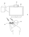
- FIG. 1 shows a configuration example of an information processing system to which the present embodiment can be applied.
- the information processing system 8 includes an imaging device 12 for capturing an object, an information processing device 10 for performing information processing based on the captured image, a flat display 16 for displaying an image obtained as a result of the information processing, and a head mounted display (Hereinafter referred to as "HMD") 18 includes an input device 14 operated by the user.
- HMD head mounted display
- the information processing device 10, the imaging device 12, the input device 14, the flat panel display 16, and the HMD 18 may be connected by a wired cable or may be connected by a known wireless communication technology such as Bluetooth (registered trademark). Further, depending on information processing performed by the information processing apparatus 10, the input device 14, the flat panel display 16, and the HMD 18 may be selectively introduced. Moreover, the external appearance shape of these apparatuses is not restricted to what is shown in figure. Furthermore, two or more of these devices may be integrally provided. For example, the information processing apparatus 10, the input device 14, and the flat panel display 16 may be realized by a portable terminal or the like provided with them.
- the imaging device 12 generates output data of a captured image by performing general processing such as demosaicing processing on a camera that captures an object such as a user at a predetermined frame rate, and generates output data of the captured image. And a sending mechanism.
- the camera is a stereo camera in which general visible light sensors such as a charge coupled device (CCD) sensor and a complementary metal oxide semiconductor (CMOS) sensor are disposed at right and left at known intervals.
- CCD charge coupled device
- CMOS complementary metal oxide semiconductor
- the information processing apparatus 10 performs necessary information processing using data transmitted from the imaging apparatus 12 and generates output data such as an image and a sound.
- the content of the process performed by the information processing apparatus 10 is not particularly limited, and may be determined as appropriate depending on the function required by the user or the content of the application. For example, by performing tracking processing on a captured image, a game in which a character reflecting the user's action as an object appears is made to progress, or the user's action is converted into a command input to perform information processing .
- the movement of the input device 14 may be acquired using a marker provided on the input device 14. Also, by tracking a plurality of markers provided on the outer surface of the HMD 18, the position and posture of the head of the user wearing the HMD 18 can be specified, and the virtual world seen from the viewpoint that moves correspondingly can be displayed on the HMD 18 Good.
- the output data generated by the information processing apparatus 10 is transmitted to at least one of the HMD 18 and the flat panel display 16.
- the HMD 18 is a display device that displays an image on a display panel such as an organic EL panel positioned in front of the user when the user wears the head.
- the images may be stereoscopically viewed by generating parallax images viewed from the left and right viewpoints and displaying them on the left and right areas formed by dividing the display screen.
- the present embodiment is not limited to this, and one image may be displayed on the entire display screen.
- the HMD 18 may further include a speaker or an earphone that outputs sound at a position corresponding to the user's ear.
- the flat panel display 16 may be a television having a display for outputting a two-dimensional image and a speaker for outputting an audio, such as a liquid crystal television, an organic EL television, a plasma television, a PC display or the like. Alternatively, it may be a display and a speaker of a tablet terminal or a portable terminal.
- the input device 14 receives requests such as start and end of processing, selection of functions, and input of various commands by user operation, and supplies the information processing device 10 as an electric signal.
- the input device 14 may be realized by any one or a combination of general input devices such as a game controller, a keyboard, a mouse, a joystick, a touch pad provided on the display screen of the flat panel display 16, and the like.
- the input device 14 may further include a light emission marker made up of elements emitting light of a predetermined color or a set thereof. In this case, when the information processing apparatus 10 tracks the movement of the marker using the captured image, the movement of the input device 14 can be used as the user operation.
- the input device 14 may be configured only with a light emission marker and a mechanism for gripping the same.
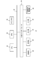
- FIG. 2 shows the internal circuit configuration of the information processing apparatus 10.
- the information processing apparatus 10 includes a central processing unit (CPU) 22, a graphics processing unit (GPU) 24, and a main memory 26. These units are connected to one another via a bus 30. An input / output interface 28 is further connected to the bus 30.
- CPU central processing unit
- GPU graphics processing unit
- main memory 26 main memory
- the I / O interface 28 includes a peripheral device interface such as USB or IEEE 1394, a communication unit 32 including a wired or wireless LAN network interface, a storage unit 34 such as a hard disk drive or nonvolatile memory, data to the flat panel display 16 or the HMD 18
- An output unit 36 for outputting the data an input unit 38 for inputting data from the imaging device 12 and the input device 14, and a recording medium drive unit 40 for driving a removable recording medium such as a magnetic disk, an optical disk or a semiconductor memory are connected.
- the CPU 22 controls the entire information processing apparatus 10 by executing the operating system stored in the storage unit 34.
- the CPU 22 also executes various programs read from the removable storage medium and loaded into the main memory 26 or downloaded via the communication unit 32.
- the GPU 24 has a function of a geometry engine and a function of a rendering processor, performs drawing processing according to a drawing command from the CPU 22, and stores a display image in a frame buffer (not shown). Then, the display image stored in the frame buffer is converted into a video signal and output to the output unit 36.
- the main memory 26 is configured by a RAM (Random Access Memory), and stores programs and data necessary for processing.
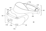
- FIG. 3 shows an example of the appearance of the HMD 18.
- the HMD 18 includes an output mechanism unit 102 and a mounting mechanism unit 104.
- the mounting mechanism unit 104 includes a mounting band 106 that turns around the head and achieves fixation of the device by being worn by the user.
- the mounting band 106 is made of a material or a structure whose length can be adjusted to fit the head circumference of each user. For example, an elastic body such as rubber may be used, or a buckle or a gear may be used.
- the output mechanism section 102 includes a housing 108 shaped to cover the left and right eyes when the HMD 18 is worn by the user, and the display mechanism internally includes a display panel so as to face the eyes when worn. Then, on the outer surface of the housing 108, light emitting markers 110a, 110b, 110c, 110d, 110e and the like are provided. Although the number and arrangement of the light emission markers are not particularly limited, they are provided at the four corners and the center of the front surface of the case of the output mechanism section 102 in the present embodiment. Furthermore, the light emission markers 110 f and 110 g may be provided on both sides behind the mounting band 106. The light emitting markers 110d and 110e are on the lower side of the output mechanism section 102, and the light emitting markers 110f and 110g are on the outside of the mounting band 106 and can not be originally seen from the viewpoint of FIG.
- the information processing apparatus 10 is basically based on detecting an image of a light emission marker provided on an object such as the HMD 18 from a captured image, and acquiring the position and posture of the object based thereon. Thereby, as described above, the user's own position and posture are acquired, and the virtual world from the viewpoint according to it is displayed on the HMD 18, and information processing is performed according to the user's movement and position.
- the light emission marker is not limited to the one provided in the HMD 18, but may be one provided in the input device 14 or one directly attached to the user's body.
- the light emission marker may be attached to the object to be tracked.
- the display device is not limited to the HMD 18 in the case where the position and posture of the human head are not tracked using the HMD 18.
- the marker may be any object or figure that has a predetermined color or shape and can be distinguished from other objects in the imaging space, and is not limited to the light emitter.
- FIG. 4 is a diagram for describing a method of tracking an object using an image captured by the imaging device 12.
- the imaging device 12 is configured of a stereo camera in which two cameras are disposed at right and left at known intervals.
- a pair of images stereo images
- parallax occurs in the lateral direction of the image depending on the distance between the cameras and the distance from the camera of the subject.
- the images of the five markers shown by hatching are in the image 120a from the left viewpoint and to the right in the image 120b from the right viewpoint. From the left.
- the method of calculating the distance from the imaging plane based on the difference in the lateral position of the image in the stereo image is a general one based on the principle of triangulation. Then, based on the calculated distance, the position of the marker in the real space, that is, the position of the object can be specified by back-projecting the position coordinates of the marker on the image plane to the real space.
- the longitudinal positions of the images of the same marker in the stereo images 120a and 120b (for example, y_l and y_r) Matches.
- the vertical positions coincide with each other, it is easy to specify the image of the corresponding marker in both images.
- a slight deviation of the optical axis may occur due to the assembly accuracy at the time of manufacture.
- FIG. 5 shows a stereo image when the optical axis (especially pitch angle) of the left and right cameras or the position in the longitudinal direction is shifted.
- the vertical position (eg, y_l) of the image of the marker in the image 120a from the left viewpoint is above the position (eg, y_r) of the image of the corresponding marker in the image 120b from the right viewpoint.
- each imaging device 12 is confirmed at the stage of manufacture, and parameters representing the positional deviation ⁇ y in the vertical direction are recorded in a non-volatile memory or the like.
- the information processing apparatus 10 reads the parameter and virtually shifts one of the stereo images captured by the imaging apparatus 12 by ⁇ y on the image plane virtually, so that the images can be vertically extracted. Align the position.
- the corrected image 122 in which a frame is indicated by a dotted line is generated by moving the image 120 b from the right viewpoint upward by ⁇ y.
- the image 120a from the left viewpoint with the corrected image 122, the image of the corresponding marker can be easily identified based on the position in the vertical direction.
- the positional deviation ⁇ y may change due to various factors such as heat generated inside the device during operation, an externally applied impact such as falling, and aging of parts. . Therefore, in order to maintain the processing accuracy, it is desirable that the user recalibrate independently and update the setting value of the positional deviation ⁇ y.
- the suitable timing is not common because it also depends on the use situation and the like, and it is also difficult for the user himself to recognize the necessity.
- the accuracy is further improved using an image captured under conditions or environment suitable for such block matching.
- the information processing apparatus 10 determines the timing at which the calibration process is necessary, so that the tracking accuracy can be maintained with the minimum amount of time and effort.
- FIG. 6 shows the configuration of functional blocks of the information processing apparatus 10.
- each functional block shown in FIG. 6 can be realized by the configuration of the CPU, GPU, memory, etc. shown in FIG. 2, and in software, it is a data input function loaded into the memory from a recording medium etc. It is realized by a program that exhibits various functions such as a data holding function, an image processing function, and an input / output function. Therefore, it is understood by those skilled in the art that these functional blocks can be realized in various forms by hardware only, software only, or a combination thereof, and is not limited to any of them.
- the information processing apparatus 10 includes an input information acquisition unit 50 for acquiring input information from the input device 14, a photographed image acquisition unit 52 for acquiring data of a photographed image from the imaging device 12, and tracking for tracking an object based on an image of a marker.
- the input information acquisition unit 50 acquires the content of the user operation from the input device 14.
- the user operation may be a general information processing such as selection of an application to be executed, start / end of processing, and command input.
- the input information acquisition unit 50 supplies the information acquired from the input device 14 to the photographed image acquisition unit 52, the information processing unit 62, and the calibration unit 68 according to the contents.
- the photographed image acquisition unit 52 acquires data of a photographed image obtained by moving image photographing of the imaging device 12 at a predetermined frame rate.
- the photographed image acquisition unit 52 further controls the start / end of photographing in the imaging device 12 according to the processing start / end request from the user acquired by the input information acquisition unit 50, or according to the processing result in the information processing unit 62.
- the type of data acquired from the imaging device 12 may be controlled.
- the tracking processing unit 54 tracks an object such as the HMD 18 based on the captured image, and specifies the movement or the position.
- the tracking processing unit 54 includes a corresponding marker specifying unit 58, a position information acquisition unit 60, and a correction data storage unit 56.
- the corresponding marker specifying unit 58 acquires data of a stereo image of each frame in which a moving image is captured from the captured image acquiring unit 52, and detects an image of a corresponding marker from both images. Then, the position coordinates of the image of the marker are associated and supplied to the position information acquisition unit 60 and the calibration determination unit 64.
- position coordinates means position coordinates of a predetermined place such as a center of gravity within a finite area of an image of a marker.
- the correction data storage unit 56 is a storage area in which data representing the positional deviation ⁇ y in the vertical direction of the stereo image is stored. In the initial state, the data is acquired at the time of factory shipment and the like. By reading out the data, the corresponding marker specifying unit 58 vertically shifts either image of the stereo image on the image plane based on the displacement ⁇ y that it represents, and aligns the positions of the left and right images in the vertical direction. And identify the image of the corresponding marker.
- the position information acquisition unit 60 specifies the position of the marker, and hence the object provided with it, based on the principle of triangulation, based on the difference in the lateral position of the image of the corresponding marker in the stereo image.
- the posture of the object may also be specified by using a plurality of markers and their positional relationship and the like. For example, the posture of the object can be determined by preparing a three-dimensional model of the object in advance and applying the apparent position of the marker to the three-dimensional model.
- the posture or the like may be specified in more detail by acquiring measurement values by various sensors such as an acceleration sensor included in the object and integrating it with position information obtained from the captured image.
- the position information acquisition unit 60 supplies the information on the acquired position and orientation of the target to the information processing unit 62.
- the information processing unit 62 performs information processing such as a game specified by the user.
- the movement result of the object is reflected in the information processing by acquiring the tracking result of the object from the tracking processing unit 54 for each frame.
- the content of the user operation acquired by the input information acquisition unit 50 from the input device 14 may be reflected.
- the content of the information processing performed by the information processing unit 62 using these input data is not particularly limited.
- the calibration determination unit 64 determines the timing at which calibration is required based on the difference between the position coordinates in the vertical direction among the position coordinates of the image of the corresponding marker supplied from the corresponding marker identification unit 58 of the tracking processing unit 54. judge. Specifically, in the stereo image after aligning the vertical position based on the vertical positional deviation ⁇ y set in the correction data storage unit 56, it is further monitored whether the image of the marker is shifted in the vertical direction. If a deviation exceeding the threshold is observed, it is determined that the set value of the positional deviation ⁇ y needs to be updated. Detailed processing contents will be described later.
- the output data generation unit 66 generates image and sound data to be output as a result of the information processing in accordance with the request from the information processing unit 62.
- the virtual world viewed from the viewpoint corresponding to the position and posture of the head of the user is drawn as the left and right parallax images. If this parallax image is displayed in front of the left and right eyes in the HMD 18 or the sound in the virtual world is output, the user can feel as if it were in the virtual world.
- various information processing can be realized using tracking results and user operations.
- the output data generation unit 66 When the calibration determination unit 64 determines that the need for calibration has occurred, the output data generation unit 66 also generates a display image for notifying the user of that. The generated output data is appropriately output to the HMD 18 or the flat panel display 16 so as to be output as an image or sound.
- the calibration unit 68 performs predetermined calibration processing, and updates data representing the positional deviation ⁇ y stored in the correction data storage unit 56.
- the operation of the calibration unit 68 is based on activation by the user notified of the necessity of calibration via the input device 14.
- the calibration unit 68 extracts corresponding points, for example, by scanning the entire surface of the stereo image in pixel units or sub-pixel units, compares the position coordinates, etc. get.
- the tracking processing unit 54 acquires more detailed information than the processing of detecting the image of the marker in order to track the object. Therefore, it should be noted that the image processing conditions such as the brightness and the photographing environment of the subject, the photographing conditions such as the exposure time, and the gain value are often different from those in the information processing such as the game. With regard to the shooting environment, the user may be prompted using a display or the like to prepare an optimal state. As described above, even if the environment and processing conditions required by the calibration are different from those at the time of normal processing such as a game, in the present embodiment, the apparatus determines the timing to minimize the frequency of execution and the user To reduce the burden of data processing and maintain the accuracy of information processing.
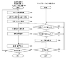
- FIG. 7 is a flowchart showing a processing procedure in which the information processing apparatus 10 according to the present embodiment determines the necessary timing of calibration while performing information processing such as a game.
- the flow on the left is a procedure in which the tracking processing unit 54, the information processing unit 62, and the output data generation unit 66 mainly perform main information processing such as a game
- the flow on the right is a calibration determination unit 64. Is the procedure of the process of determining the timing which needs calibration in parallel to it. The latter is performed in a state in which the user is not aware of the main information processing such as a game, that is, in the background.
- the photographed image acquisition unit 52 requests the imaging device 12 to start photographing, and the stereo transmitted according to the request.
- the tracking processing unit 54 acquires image data (S10).
- the corresponding marker identification unit 58 of the tracking processing unit 54 performs correction to align the vertical position of the acquired stereo image, based on the data representing the positional deviation ⁇ y in the vertical direction stored in the correction data storage unit 56 ( S12).
- the image of the corresponding marker in both is detected (S14).
- the corresponding marker specifying unit 58 provides the position information acquisition unit 60 and the calibration determination unit 64 of the tracking processing unit 54 with the position coordinates of the image of the corresponding marker.
- the position information acquisition unit 60 calculates the distance from the imaging plane of the marker from the difference in the position of the image of the corresponding marker in the lateral direction, and acquires information on the position and orientation of the target (S16).
- the information processing unit 62 causes the information processing such as a game to progress (S18), causes the output data generation unit 66 to generate output data such as an image, and causes the HMD 18 or the like to output the output data (S20).
- the calibration determination unit 64 acquires the position coordinates of the image of the corresponding marker provided from the corresponding marker identification unit 58, first, was position data effective to determine the necessity of calibration obtained? It is determined whether or not it is (S24).
- "effective position data” is position data having sufficient reliability to determine the need for calibration.
- the calibration determination unit 64 determines that calibration is necessary when the vertical displacement of the image of the corresponding marker in the stereo image exceeds a predetermined threshold.
- the determination process is performed using only the position coordinates of the marker detected from, for example, a stereo image of one frame, it is determined that it is necessary at a timing where calibration is not originally necessary due to a temporary error of the position coordinates. It is conceivable that As described above, it is desirable to scrutinize the validity of the position data that is the source of the determination so as not to excessively determine the timing at which the calibration is necessary and to increase the burden on the user.
- the output data generation unit 66 generates image data for notification and outputs it from the HMD 18 or the like (S20). The above processing is repeated for each frame of a moving image captured by the imaging device 12 (N in S22 and N in S32), and when the user requests the end of the information processing via the input device 14 or the game ends, etc. All processing ends (Y in S22 and Y in S32).
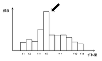
- FIG. 8 is a view for explaining an example of a method of determining whether or not valid position data has been obtained in S24 of FIG.
- the validity of the data is confirmed by accumulating the longitudinal displacement amount of the image of the corresponding marker for a certain period. Specifically, every time the data of the position coordinate of the corresponding marker is supplied from the corresponding marker identifying unit 58, the difference in the vertical direction is defined as the "displacement amount", and the frequency is counted for each deviation amount. As shown in FIG. 4, when five markers appear in each of the stereo images, the frequency of one of the deviation amounts is added a total of five times per frame.
- a histogram of “frequency” with respect to “displacement amount” grows. Then, as indicated by the arrows, the shift amount "Y5" which is clearly superior to the other from the viewpoint of frequency is used as valid position data to determine the necessity of calibration. For example, the deviation amount at which the frequency first exceeds the predetermined threshold value, the deviation amount at which the highest frequency is obtained when the predetermined time has elapsed from the start of data accumulation, the highest frequency at the point when the frequency distribution converges The obtained amount of deviation or the like is referred to as “a significant amount of deviation”. It may be determined by performing statistical processing using a standard deviation or the like.
- the next histogram is formed, discarding the previous histogram and counting the frequency from zero.
- the previous result may be included at a certain rate by adding the frequency after that to the frequency of each shift amount of the previous histogram multiplied by a predetermined rate less than 1.
- the frequency of addition may be weighted according to the situation when the corresponding marker identification unit 58 acquires the position coordinates of the marker. For example, when the image of the marker in the image is small, it is considered that the position coordinate is likely to include an error because the distance from the imaging plane to the marker is long or a part of the marker is out of view.
- weighting may be performed such that the value of the frequency of addition at one time decreases as the marker image decreases.
- the image when there is a light emitter other than a marker such as illumination or a display of a terminal in the field of view, the image may be erroneously recognized as a marker.
- the number of marker images when one object is equipped with a plurality of markers, the number of marker images may decrease depending on the orientation of the object. As the number of marker images decreases, the amount of information that it represents decreases, which makes it easier to misidentify the marker correspondence.
- weighting may be performed so that the value of the frequency to be added at one time becomes small also at these times.
- any event that affects the position coordinate of the marker or the identification accuracy of the correspondence relationship may be used for weighting the addition frequency.
- the histogram can be formed with higher accuracy, and the reliability of the amount of deviation used for determining the necessity of calibration is improved.
- the corresponding marker specifying unit 58 provides the calibration determination unit 64 with various data used for weighting, together with data of position coordinates.
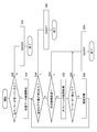
- FIG. 9 is a flowchart showing, as an example of such an embodiment, a processing procedure for confirming the validity of position data when the number of marker images in an image is used.
- the whole process corresponds to the process of S24 in FIG. 7, and the initial stage is a stage prior to newly starting storage of data of position coordinates, such as immediately after valid position data is obtained.
- the calibration determination unit 64 acquires information related to the number of marker images in the image from the corresponding marker identification unit 58 together with the data of the position coordinates.
- data accumulation of position coordinates is started (S44).
- Data accumulation of position coordinates is, for example, the formation of the histogram shown in FIG.
- the larger the number of marker images the lower the possibility of misidentification of the correspondence in the corresponding marker identification unit 58. Therefore, by starting accumulation of data triggered by that, the direction of the object changes in the subsequent accumulation period, etc., and even if the number of images decreases somewhat, the reliability of the data during accumulation is large. It is less likely to be damaged.
- the process is exited (S56). That is, the data accumulation is stopped and the histogram is discarded. If two or more images are detected in either of the stereo images of the next frame (N in S54), the frequency is added based on the positional deviation of the corresponding marker in the frame (S58).
- frequencies are added based on position coordinate data of subsequent frames (N of S46, N of S50, S52, S54 N, S58). If the dominant shift amount can be determined within a predetermined time (Y in S46), it is determined that valid data is obtained (Y in S24 of FIG. 7), and the process is exited (S48). The shift amount obtained at this time is used to determine the necessity of calibration in S26 of FIG. If a predetermined time elapses (N in S46, Y in S50) or no marker image is obtained (Y in S54), valid data can be obtained before a significant shift amount is obtained. It is determined that there is no (N in S24 of FIG. 7), and the process exits (S56). That is, the data accumulation is stopped and the histogram is discarded.
- the number of marker images used for determination in S40 and S54 is not limited to that illustrated. In addition to the number of marker images, any of the events relating to position coordinate acquisition accuracy may be adopted as the reference for triggering accumulation start and end of position coordinate data, other than the number of marker images. . In addition, whether the distance from the imaging plane of the marker is within a predetermined range, whether the image of the marker is within a predetermined range of the frame, whether the marker is occluded due to the presence of a front object, The start and end of accumulation of data of position coordinates may be determined on the basis of whether the light emission of the marker is reflected in another object or not.
- the calibration determining unit 64 acquires information on the tracking accuracy and the tracking situation from the tracking processing unit 54.
- the start and end of accumulation of data of position coordinates may be determined based on that.
- the operation of the calibration determination unit 64 may be stopped.
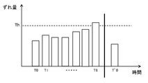
- FIG. 10 is a diagram for explaining the relationship between the effective shift amount acquired as described above and the process of determining the necessity of calibration.
- the horizontal axis represents the elapsed time
- the vertical axis represents the amounts of shift acquired at timings T0, T1,...
- the calibration determination unit 64 compares it with a predetermined threshold value Th. Then, at timing T6 when the deviation amount exceeds the threshold value, it is determined that calibration is necessary, and the user is notified.
- the threshold value Th may be stored inside the information processing apparatus 10 as the optimum value acquired in advance by experiment or the like, or may be read out from the application to be executed.
- the user activates the function of the calibration unit 68 at the timing according to his / her convenience.
- this timing is represented by a thick line.
- the calibration unit 68 acquires the positional deviation ⁇ y in the vertical direction of the stereo image strictly by block matching or the like, and stores the data representing it in the correction data storage unit 56 again.
- the tracking processing unit 54 detects an image of a marker for tracking an object, the stereo image is correctly aligned.
- the effective shift amount acquired next by the calibration determination unit 64 at the timing of T ′ 0 becomes equal to or less than the threshold value Th, and it is determined that the calibration is unnecessary. If the user does not perform calibration even though the user is notified of the necessity of calibration at timing T6, the state where the deviation amount exceeds the threshold Th continues, so the notification is also continued. . Even in this state, the user can continue information processing such as a game. At this time, even if the processing result is affected by the positional deviation, the user can recognize the cause, so that the information processing apparatus and the application can not be evaluated inappropriately or the user can be prevented from feeling stress. .
- camera calibration is performed using the amount of positional deviation in the vertical direction of the image of the marker obtained in the middle of the tracking process. Monitor the need for Then, the user is notified when the need arises and the user is urged to execute the calibration process.
- information processing system 10 information processing apparatus 12 imaging apparatus 14 input device 16 flat panel display 18 HMD 50 input information acquisition unit 52 captured image acquisition unit 54 tracking processing unit 54 correction data storage unit 58 Corresponding marker identification unit, 60 position information acquisition unit, 62 information processing unit, 64 calibration determination unit, 66 output data generation unit, 68 calibration unit, 110a luminescence marker.
- the present invention is applicable to a computer that processes various electronic contents, a display device, a game device, an information processing device, an image processing device, and a system including them.
Landscapes
- Engineering & Computer Science (AREA)
- Multimedia (AREA)
- Theoretical Computer Science (AREA)
- Physics & Mathematics (AREA)
- Human Computer Interaction (AREA)
- General Physics & Mathematics (AREA)
- General Engineering & Computer Science (AREA)
- Signal Processing (AREA)
- Computer Vision & Pattern Recognition (AREA)
- Electromagnetism (AREA)
- Remote Sensing (AREA)
- Radar, Positioning & Navigation (AREA)
- Biomedical Technology (AREA)
- General Health & Medical Sciences (AREA)
- Health & Medical Sciences (AREA)
- User Interface Of Digital Computer (AREA)
- Length Measuring Devices By Optical Means (AREA)
- Position Input By Displaying (AREA)
- Testing, Inspecting, Measuring Of Stereoscopic Televisions And Televisions (AREA)
- Measurement Of Optical Distance (AREA)
Priority Applications (3)
| Application Number | Priority Date | Filing Date | Title |
|---|---|---|---|
| CN201680027680.3A CN107960123A (zh) | 2015-05-20 | 2016-05-13 | 信息处理设备和信息处理方法 |
| EP16796424.6A EP3299937B1 (en) | 2015-05-20 | 2016-05-13 | Information processing device and information processing method |
| US15/567,774 US10638120B2 (en) | 2015-05-20 | 2016-05-13 | Information processing device and information processing method for stereoscopic image calibration |
Applications Claiming Priority (2)
| Application Number | Priority Date | Filing Date | Title |
|---|---|---|---|
| JP2015-103183 | 2015-05-20 | ||
| JP2015103183A JP6345627B2 (ja) | 2015-05-20 | 2015-05-20 | 情報処理装置および情報処理方法 |
Publications (1)
| Publication Number | Publication Date |
|---|---|
| WO2016186031A1 true WO2016186031A1 (ja) | 2016-11-24 |
Family
ID=57320223
Family Applications (1)
| Application Number | Title | Priority Date | Filing Date |
|---|---|---|---|
| PCT/JP2016/064314 Ceased WO2016186031A1 (ja) | 2015-05-20 | 2016-05-13 | 情報処理装置および情報処理方法 |
Country Status (5)
| Country | Link |
|---|---|
| US (1) | US10638120B2 (enExample) |
| EP (1) | EP3299937B1 (enExample) |
| JP (1) | JP6345627B2 (enExample) |
| CN (1) | CN107960123A (enExample) |
| WO (1) | WO2016186031A1 (enExample) |
Families Citing this family (10)
| Publication number | Priority date | Publication date | Assignee | Title |
|---|---|---|---|---|
| JP6707022B2 (ja) * | 2016-12-26 | 2020-06-10 | 日立オートモティブシステムズ株式会社 | ステレオカメラ |
| JP7330159B2 (ja) * | 2017-07-20 | 2023-08-21 | 株式会社ソニー・インタラクティブエンタテインメント | 情報処理装置および位置情報取得方法 |
| CN110135861B (zh) * | 2019-04-24 | 2024-03-05 | 平安科技(深圳)有限公司 | 信息通知方法、装置、计算机设备及存储介质 |
| US11190755B2 (en) | 2019-06-12 | 2021-11-30 | Sony Interactive Entertainment Inc. | Asymmetric arrangement of left and right displays to improve image quality for a stereoscopic head-mounted display (HMD) |
| JP2021033334A (ja) * | 2019-08-13 | 2021-03-01 | ソニーセミコンダクタソリューションズ株式会社 | 情報処理装置、情報処理方法、および情報処理プログラム |
| WO2023095717A1 (ja) * | 2021-11-25 | 2023-06-01 | ソニーグループ株式会社 | 表示装置、表示方法及び表示プログラム |
| GB2614326B (en) * | 2021-12-31 | 2024-10-02 | Sony Interactive Entertainment Europe Ltd | Apparatus and method for virtual reality |
| JP7756065B2 (ja) * | 2022-12-08 | 2025-10-17 | Astemo株式会社 | 画像処理装置及び画像処理方法 |
| US12423769B2 (en) | 2023-06-15 | 2025-09-23 | Microsoft Technology Licensing, Llc | Selecting a reprojection distance based on the focal length of a camera |
| US12413696B2 (en) * | 2023-06-15 | 2025-09-09 | Microsoft Technology Licensing, Llc | Techniques for correcting vertical angular image misalignment in extended reality systems |
Citations (3)
| Publication number | Priority date | Publication date | Assignee | Title |
|---|---|---|---|---|
| WO2011058876A1 (ja) * | 2009-11-13 | 2011-05-19 | 富士フイルム株式会社 | 測距装置、測距方法、測距プログラムおよび測距システムならびに撮像装置 |
| JP2012175685A (ja) * | 2011-02-24 | 2012-09-10 | Nintendo Co Ltd | 情報処理プログラム、撮像装置、撮像方法及び撮像システム |
| JP2015001465A (ja) * | 2013-06-17 | 2015-01-05 | キヤノン株式会社 | 三次元位置計測装置、及び三次元位置計測装置のキャリブレーションずれ判定方法 |
Family Cites Families (21)
| Publication number | Priority date | Publication date | Assignee | Title |
|---|---|---|---|---|
| RU2000102890A (ru) | 1998-05-19 | 2002-03-27 | Сони Компьютер Энтертейнмент Инк. (Jp) | Устройство и способ обработки изображений и распространяемый носитель |
| US7236199B2 (en) * | 2003-07-07 | 2007-06-26 | Toshikazu Hori | Multi-tap camera |
| JP4957134B2 (ja) * | 2006-09-12 | 2012-06-20 | 株式会社日立製作所 | 距離計測装置 |
| US8781151B2 (en) * | 2006-09-28 | 2014-07-15 | Sony Computer Entertainment Inc. | Object detection using video input combined with tilt angle information |
| US20080117290A1 (en) * | 2006-10-18 | 2008-05-22 | Mgc Works, Inc. | Apparatus, system and method for generating stereoscopic images and correcting for vertical parallax |
| US8286196B2 (en) * | 2007-05-03 | 2012-10-09 | Apple Inc. | Parallel runtime execution on multiple processors |
| CN102043673B (zh) * | 2009-10-21 | 2015-06-03 | Sap欧洲公司 | 并行处理中执行任务的节点数量的优化选择系统及方法 |
| US8669990B2 (en) * | 2009-12-31 | 2014-03-11 | Intel Corporation | Sharing resources between a CPU and GPU |
| JP5898842B2 (ja) * | 2010-01-14 | 2016-04-06 | 任天堂株式会社 | 携帯型情報処理装置、携帯型ゲーム装置 |
| WO2011133140A2 (en) * | 2010-04-20 | 2011-10-27 | Hewlett-Packard Development Company, L.P. | Stereo vision viewing systems |
| US8602887B2 (en) * | 2010-06-03 | 2013-12-10 | Microsoft Corporation | Synthesis of information from multiple audiovisual sources |
| JP5440461B2 (ja) * | 2010-09-13 | 2014-03-12 | 株式会社リコー | 校正装置、距離計測システム、校正方法および校正プログラム |
| JP5870510B2 (ja) * | 2010-09-14 | 2016-03-01 | 株式会社リコー | ステレオカメラ装置、校正方法およびプログラム |
| JP5481337B2 (ja) * | 2010-09-24 | 2014-04-23 | 株式会社東芝 | 画像処理装置 |
| US9188973B2 (en) * | 2011-07-08 | 2015-11-17 | Restoration Robotics, Inc. | Calibration and transformation of a camera system's coordinate system |
| WO2013069050A1 (ja) * | 2011-11-07 | 2013-05-16 | 株式会社ソニー・コンピュータエンタテインメント | 画像生成装置および画像生成方法 |
| US9503703B1 (en) * | 2012-10-05 | 2016-11-22 | Amazon Technologies, Inc. | Approaches for rectifying stereo cameras |
| CN103792667B (zh) * | 2012-10-30 | 2016-06-01 | 财团法人工业技术研究院 | 立体摄像装置、自动校正装置与校正方法 |
| JP2014138331A (ja) * | 2013-01-17 | 2014-07-28 | Ricoh Co Ltd | 撮影装置及びプログラム |
| EP3197156A4 (en) * | 2014-07-28 | 2018-03-21 | Olympus Corporation | Control device for stereoscopic viewing device, stereoscopic viewing system, and control method for stereoscopic viewing device |
| US20170070731A1 (en) * | 2015-09-04 | 2017-03-09 | Apple Inc. | Single And Multi-Camera Calibration |
-
2015
- 2015-05-20 JP JP2015103183A patent/JP6345627B2/ja active Active
-
2016
- 2016-05-13 CN CN201680027680.3A patent/CN107960123A/zh active Pending
- 2016-05-13 WO PCT/JP2016/064314 patent/WO2016186031A1/ja not_active Ceased
- 2016-05-13 EP EP16796424.6A patent/EP3299937B1/en active Active
- 2016-05-13 US US15/567,774 patent/US10638120B2/en active Active
Patent Citations (3)
| Publication number | Priority date | Publication date | Assignee | Title |
|---|---|---|---|---|
| WO2011058876A1 (ja) * | 2009-11-13 | 2011-05-19 | 富士フイルム株式会社 | 測距装置、測距方法、測距プログラムおよび測距システムならびに撮像装置 |
| JP2012175685A (ja) * | 2011-02-24 | 2012-09-10 | Nintendo Co Ltd | 情報処理プログラム、撮像装置、撮像方法及び撮像システム |
| JP2015001465A (ja) * | 2013-06-17 | 2015-01-05 | キヤノン株式会社 | 三次元位置計測装置、及び三次元位置計測装置のキャリブレーションずれ判定方法 |
Non-Patent Citations (1)
| Title |
|---|
| See also references of EP3299937A4 * |
Also Published As
| Publication number | Publication date |
|---|---|
| US20180167607A1 (en) | 2018-06-14 |
| JP6345627B2 (ja) | 2018-06-20 |
| EP3299937A1 (en) | 2018-03-28 |
| EP3299937B1 (en) | 2023-03-01 |
| US10638120B2 (en) | 2020-04-28 |
| CN107960123A (zh) | 2018-04-24 |
| EP3299937A4 (en) | 2019-01-16 |
| JP2016218758A (ja) | 2016-12-22 |
Similar Documents
| Publication | Publication Date | Title |
|---|---|---|
| JP6345627B2 (ja) | 情報処理装置および情報処理方法 | |
| JP6514089B2 (ja) | 情報処理装置、情報処理システム、および情報処理方法 | |
| CN108139204B (zh) | 信息处理装置、位置和/或姿态的估计方法及记录介质 | |
| JP6465672B2 (ja) | 情報処理装置および情報処理方法 | |
| CN120722577A (zh) | 头戴式显示器跟踪系统 | |
| JP2016019194A (ja) | 画像処理装置、画像処理方法、および画像投影装置 | |
| JP6768933B2 (ja) | 情報処理装置、情報処理システム、および画像処理方法 | |
| CN106210699B (zh) | 信息处理装置、信息处理装置的控制方法及图像处理系统 | |
| JP2019184830A5 (enExample) | ||
| US20170061695A1 (en) | Wearable display apparatus, information processing apparatus, and control method therefor | |
| JP6494305B2 (ja) | 情報処理装置、表示装置、および情報処理方法 | |
| WO2017199860A1 (ja) | 情報処理装置、情報処理システム、撮像装置、ヘッドマウントディスプレイ、および情報処理方法 | |
| JP6499993B2 (ja) | 情報処理装置、情報処理システム、および情報処理方法 | |
| CN108139203B (zh) | 信息处理设备和位置信息获取方法 | |
| US10917566B2 (en) | Optimum situation determination imaging method and device for performing the method | |
| KR101845612B1 (ko) | 투구 연습을 통한 3차원 정보 획득 시스템 및 카메라 파라미터 산출 방법 | |
| JP7343237B2 (ja) | 追跡方法 | |
| CN113271852A (zh) | 注意力判定装置、注意力判定系统、注意力判定方法和程序 | |
| JP7323234B2 (ja) | ガイド方法 | |
| KR20260054175A (ko) | 이미지 출력 장치 및 그 동작 방법 | |
| WO2023157498A1 (ja) | 情報処理装置、デバイス速度推定方法およびデバイス位置推定方法 | |
| CN119065133A (zh) | 头戴显示设备的控制方法、头戴显示设备及存储介质 |
Legal Events
| Date | Code | Title | Description |
|---|---|---|---|
| 121 | Ep: the epo has been informed by wipo that ep was designated in this application |
Ref document number: 16796424 Country of ref document: EP Kind code of ref document: A1 |
|
| WWE | Wipo information: entry into national phase |
Ref document number: 15567774 Country of ref document: US |
|
| NENP | Non-entry into the national phase |
Ref country code: DE |