WO2016186031A1 - Information processing device and information processing method - Google Patents
Information processing device and information processing method Download PDFInfo
- Publication number
- WO2016186031A1 WO2016186031A1 PCT/JP2016/064314 JP2016064314W WO2016186031A1 WO 2016186031 A1 WO2016186031 A1 WO 2016186031A1 JP 2016064314 W JP2016064314 W JP 2016064314W WO 2016186031 A1 WO2016186031 A1 WO 2016186031A1
- Authority
- WO
- WIPO (PCT)
- Prior art keywords
- image
- information processing
- calibration
- stereo
- information
- Prior art date
Links
Images


Classifications
-
- H—ELECTRICITY
- H04—ELECTRIC COMMUNICATION TECHNIQUE
- H04N—PICTORIAL COMMUNICATION, e.g. TELEVISION
- H04N13/00—Stereoscopic video systems; Multi-view video systems; Details thereof
- H04N13/30—Image reproducers
- H04N13/332—Displays for viewing with the aid of special glasses or head-mounted displays [HMD]
-
- A—HUMAN NECESSITIES
- A63—SPORTS; GAMES; AMUSEMENTS
- A63F—CARD, BOARD, OR ROULETTE GAMES; INDOOR GAMES USING SMALL MOVING PLAYING BODIES; VIDEO GAMES; GAMES NOT OTHERWISE PROVIDED FOR
- A63F13/00—Video games, i.e. games using an electronically generated display having two or more dimensions
- A63F13/20—Input arrangements for video game devices
- A63F13/21—Input arrangements for video game devices characterised by their sensors, purposes or types
- A63F13/213—Input arrangements for video game devices characterised by their sensors, purposes or types comprising photodetecting means, e.g. cameras, photodiodes or infrared cells
-
- A—HUMAN NECESSITIES
- A63—SPORTS; GAMES; AMUSEMENTS
- A63F—CARD, BOARD, OR ROULETTE GAMES; INDOOR GAMES USING SMALL MOVING PLAYING BODIES; VIDEO GAMES; GAMES NOT OTHERWISE PROVIDED FOR
- A63F13/00—Video games, i.e. games using an electronically generated display having two or more dimensions
- A63F13/20—Input arrangements for video game devices
- A63F13/22—Setup operations, e.g. calibration, key configuration or button assignment
-
- A—HUMAN NECESSITIES
- A63—SPORTS; GAMES; AMUSEMENTS
- A63F—CARD, BOARD, OR ROULETTE GAMES; INDOOR GAMES USING SMALL MOVING PLAYING BODIES; VIDEO GAMES; GAMES NOT OTHERWISE PROVIDED FOR
- A63F13/00—Video games, i.e. games using an electronically generated display having two or more dimensions
- A63F13/20—Input arrangements for video game devices
- A63F13/23—Input arrangements for video game devices for interfacing with the game device, e.g. specific interfaces between game controller and console
-
- G—PHYSICS
- G01—MEASURING; TESTING
- G01B—MEASURING LENGTH, THICKNESS OR SIMILAR LINEAR DIMENSIONS; MEASURING ANGLES; MEASURING AREAS; MEASURING IRREGULARITIES OF SURFACES OR CONTOURS
- G01B11/00—Measuring arrangements characterised by the use of optical techniques
-
- G—PHYSICS
- G01—MEASURING; TESTING
- G01B—MEASURING LENGTH, THICKNESS OR SIMILAR LINEAR DIMENSIONS; MEASURING ANGLES; MEASURING AREAS; MEASURING IRREGULARITIES OF SURFACES OR CONTOURS
- G01B11/00—Measuring arrangements characterised by the use of optical techniques
- G01B11/26—Measuring arrangements characterised by the use of optical techniques for measuring angles or tapers; for testing the alignment of axes
-
- G—PHYSICS
- G01—MEASURING; TESTING
- G01C—MEASURING DISTANCES, LEVELS OR BEARINGS; SURVEYING; NAVIGATION; GYROSCOPIC INSTRUMENTS; PHOTOGRAMMETRY OR VIDEOGRAMMETRY
- G01C3/00—Measuring distances in line of sight; Optical rangefinders
- G01C3/02—Details
- G01C3/06—Use of electric means to obtain final indication
-
- G—PHYSICS
- G06—COMPUTING; CALCULATING OR COUNTING
- G06F—ELECTRIC DIGITAL DATA PROCESSING
- G06F3/00—Input arrangements for transferring data to be processed into a form capable of being handled by the computer; Output arrangements for transferring data from processing unit to output unit, e.g. interface arrangements
- G06F3/01—Input arrangements or combined input and output arrangements for interaction between user and computer
- G06F3/011—Arrangements for interaction with the human body, e.g. for user immersion in virtual reality
- G06F3/012—Head tracking input arrangements
-
- G—PHYSICS
- G06—COMPUTING; CALCULATING OR COUNTING
- G06F—ELECTRIC DIGITAL DATA PROCESSING
- G06F3/00—Input arrangements for transferring data to be processed into a form capable of being handled by the computer; Output arrangements for transferring data from processing unit to output unit, e.g. interface arrangements
- G06F3/01—Input arrangements or combined input and output arrangements for interaction between user and computer
- G06F3/03—Arrangements for converting the position or the displacement of a member into a coded form
- G06F3/033—Pointing devices displaced or positioned by the user, e.g. mice, trackballs, pens or joysticks; Accessories therefor
- G06F3/0346—Pointing devices displaced or positioned by the user, e.g. mice, trackballs, pens or joysticks; Accessories therefor with detection of the device orientation or free movement in a 3D space, e.g. 3D mice, 6-DOF [six degrees of freedom] pointers using gyroscopes, accelerometers or tilt-sensors
-
- G—PHYSICS
- G06—COMPUTING; CALCULATING OR COUNTING
- G06T—IMAGE DATA PROCESSING OR GENERATION, IN GENERAL
- G06T7/00—Image analysis
- G06T7/20—Analysis of motion
- G06T7/246—Analysis of motion using feature-based methods, e.g. the tracking of corners or segments
-
- G—PHYSICS
- G06—COMPUTING; CALCULATING OR COUNTING
- G06T—IMAGE DATA PROCESSING OR GENERATION, IN GENERAL
- G06T7/00—Image analysis
- G06T7/80—Analysis of captured images to determine intrinsic or extrinsic camera parameters, i.e. camera calibration
- G06T7/85—Stereo camera calibration
-
- H—ELECTRICITY
- H04—ELECTRIC COMMUNICATION TECHNIQUE
- H04N—PICTORIAL COMMUNICATION, e.g. TELEVISION
- H04N13/00—Stereoscopic video systems; Multi-view video systems; Details thereof
- H04N13/10—Processing, recording or transmission of stereoscopic or multi-view image signals
- H04N13/194—Transmission of image signals
-
- H—ELECTRICITY
- H04—ELECTRIC COMMUNICATION TECHNIQUE
- H04N—PICTORIAL COMMUNICATION, e.g. TELEVISION
- H04N13/00—Stereoscopic video systems; Multi-view video systems; Details thereof
- H04N13/20—Image signal generators
- H04N13/204—Image signal generators using stereoscopic image cameras
- H04N13/239—Image signal generators using stereoscopic image cameras using two 2D image sensors having a relative position equal to or related to the interocular distance
-
- H—ELECTRICITY
- H04—ELECTRIC COMMUNICATION TECHNIQUE
- H04N—PICTORIAL COMMUNICATION, e.g. TELEVISION
- H04N13/00—Stereoscopic video systems; Multi-view video systems; Details thereof
- H04N13/20—Image signal generators
- H04N13/204—Image signal generators using stereoscopic image cameras
- H04N13/246—Calibration of cameras
-
- H—ELECTRICITY
- H04—ELECTRIC COMMUNICATION TECHNIQUE
- H04N—PICTORIAL COMMUNICATION, e.g. TELEVISION
- H04N13/00—Stereoscopic video systems; Multi-view video systems; Details thereof
- H04N13/30—Image reproducers
-
- H—ELECTRICITY
- H04—ELECTRIC COMMUNICATION TECHNIQUE
- H04N—PICTORIAL COMMUNICATION, e.g. TELEVISION
- H04N17/00—Diagnosis, testing or measuring for television systems or their details
- H04N17/002—Diagnosis, testing or measuring for television systems or their details for television cameras
-
- H—ELECTRICITY
- H04—ELECTRIC COMMUNICATION TECHNIQUE
- H04N—PICTORIAL COMMUNICATION, e.g. TELEVISION
- H04N5/00—Details of television systems
- H04N5/64—Constructional details of receivers, e.g. cabinets or dust covers
-
- G—PHYSICS
- G02—OPTICS
- G02B—OPTICAL ELEMENTS, SYSTEMS OR APPARATUS
- G02B27/00—Optical systems or apparatus not provided for by any of the groups G02B1/00 - G02B26/00, G02B30/00
- G02B27/01—Head-up displays
- G02B27/0101—Head-up displays characterised by optical features
- G02B2027/014—Head-up displays characterised by optical features comprising information/image processing systems
-
- G—PHYSICS
- G06—COMPUTING; CALCULATING OR COUNTING
- G06T—IMAGE DATA PROCESSING OR GENERATION, IN GENERAL
- G06T2207/00—Indexing scheme for image analysis or image enhancement
- G06T2207/30—Subject of image; Context of image processing
- G06T2207/30204—Marker
Definitions
- the present invention relates to an information processing technique that involves detection of an object in a captured image.
- the present invention has been made in view of these problems, and an object thereof is to provide a technology capable of easily maintaining the accuracy of information processing involving tracking of an object using a captured image with less trouble for the user. is there.
- the information processing apparatus is an information processing apparatus that acquires position information of an object from an image captured by a stereo camera and performs information processing, and the image of the object is acquired from stereo images captured by the stereo camera from left and right viewpoints.
- the amount of positional deviation in the vertical direction of the stereo image is monitored based on the object detection unit to be detected and the detection result of the image of the relevant object, and camera calibration is necessary when the positional deviation amount satisfies a predetermined condition
- It is characterized by comprising a calibration determination unit that determines that there is an output data generation unit that outputs information to that effect when it is determined that camera calibration is necessary.
- This information processing method is an information processing method performed by an information processing apparatus that acquires position information of an object from an image captured by a stereo camera and performs information processing, and the target is a stereo image captured by a stereo camera from left and right viewpoints
- the amount of positional deviation in the vertical direction of the stereo image is monitored based on the step of detecting the image of the object and the detection result of the image of the object, and camera calibration is required when the amount of positional deviation satisfies a predetermined condition And a step of outputting information to that effect when it is determined that camera calibration is necessary.
- any combination of the above-described components, and one obtained by converting the expression of the present invention between a method, an apparatus, a system, a computer program, a recording medium recording a computer program, etc. are also effective as an embodiment of the present invention. .
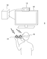
- FIG. 1 shows a configuration example of an information processing system to which the present embodiment can be applied.
- the information processing system 8 includes an imaging device 12 for capturing an object, an information processing device 10 for performing information processing based on the captured image, a flat display 16 for displaying an image obtained as a result of the information processing, and a head mounted display (Hereinafter referred to as "HMD") 18 includes an input device 14 operated by the user.
- HMD head mounted display
- the information processing device 10, the imaging device 12, the input device 14, the flat panel display 16, and the HMD 18 may be connected by a wired cable or may be connected by a known wireless communication technology such as Bluetooth (registered trademark). Further, depending on information processing performed by the information processing apparatus 10, the input device 14, the flat panel display 16, and the HMD 18 may be selectively introduced. Moreover, the external appearance shape of these apparatuses is not restricted to what is shown in figure. Furthermore, two or more of these devices may be integrally provided. For example, the information processing apparatus 10, the input device 14, and the flat panel display 16 may be realized by a portable terminal or the like provided with them.
- the imaging device 12 generates output data of a captured image by performing general processing such as demosaicing processing on a camera that captures an object such as a user at a predetermined frame rate, and generates output data of the captured image. And a sending mechanism.
- the camera is a stereo camera in which general visible light sensors such as a charge coupled device (CCD) sensor and a complementary metal oxide semiconductor (CMOS) sensor are disposed at right and left at known intervals.
- CCD charge coupled device
- CMOS complementary metal oxide semiconductor
- the information processing apparatus 10 performs necessary information processing using data transmitted from the imaging apparatus 12 and generates output data such as an image and a sound.
- the content of the process performed by the information processing apparatus 10 is not particularly limited, and may be determined as appropriate depending on the function required by the user or the content of the application. For example, by performing tracking processing on a captured image, a game in which a character reflecting the user's action as an object appears is made to progress, or the user's action is converted into a command input to perform information processing .
- the movement of the input device 14 may be acquired using a marker provided on the input device 14. Also, by tracking a plurality of markers provided on the outer surface of the HMD 18, the position and posture of the head of the user wearing the HMD 18 can be specified, and the virtual world seen from the viewpoint that moves correspondingly can be displayed on the HMD 18 Good.
- the output data generated by the information processing apparatus 10 is transmitted to at least one of the HMD 18 and the flat panel display 16.
- the HMD 18 is a display device that displays an image on a display panel such as an organic EL panel positioned in front of the user when the user wears the head.
- the images may be stereoscopically viewed by generating parallax images viewed from the left and right viewpoints and displaying them on the left and right areas formed by dividing the display screen.
- the present embodiment is not limited to this, and one image may be displayed on the entire display screen.
- the HMD 18 may further include a speaker or an earphone that outputs sound at a position corresponding to the user's ear.
- the flat panel display 16 may be a television having a display for outputting a two-dimensional image and a speaker for outputting an audio, such as a liquid crystal television, an organic EL television, a plasma television, a PC display or the like. Alternatively, it may be a display and a speaker of a tablet terminal or a portable terminal.
- the input device 14 receives requests such as start and end of processing, selection of functions, and input of various commands by user operation, and supplies the information processing device 10 as an electric signal.
- the input device 14 may be realized by any one or a combination of general input devices such as a game controller, a keyboard, a mouse, a joystick, a touch pad provided on the display screen of the flat panel display 16, and the like.
- the input device 14 may further include a light emission marker made up of elements emitting light of a predetermined color or a set thereof. In this case, when the information processing apparatus 10 tracks the movement of the marker using the captured image, the movement of the input device 14 can be used as the user operation.
- the input device 14 may be configured only with a light emission marker and a mechanism for gripping the same.
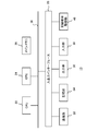
- FIG. 2 shows the internal circuit configuration of the information processing apparatus 10.
- the information processing apparatus 10 includes a central processing unit (CPU) 22, a graphics processing unit (GPU) 24, and a main memory 26. These units are connected to one another via a bus 30. An input / output interface 28 is further connected to the bus 30.
- CPU central processing unit
- GPU graphics processing unit
- main memory 26 main memory
- the I / O interface 28 includes a peripheral device interface such as USB or IEEE 1394, a communication unit 32 including a wired or wireless LAN network interface, a storage unit 34 such as a hard disk drive or nonvolatile memory, data to the flat panel display 16 or the HMD 18
- An output unit 36 for outputting the data an input unit 38 for inputting data from the imaging device 12 and the input device 14, and a recording medium drive unit 40 for driving a removable recording medium such as a magnetic disk, an optical disk or a semiconductor memory are connected.
- the CPU 22 controls the entire information processing apparatus 10 by executing the operating system stored in the storage unit 34.
- the CPU 22 also executes various programs read from the removable storage medium and loaded into the main memory 26 or downloaded via the communication unit 32.
- the GPU 24 has a function of a geometry engine and a function of a rendering processor, performs drawing processing according to a drawing command from the CPU 22, and stores a display image in a frame buffer (not shown). Then, the display image stored in the frame buffer is converted into a video signal and output to the output unit 36.
- the main memory 26 is configured by a RAM (Random Access Memory), and stores programs and data necessary for processing.
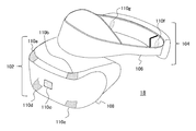
- FIG. 3 shows an example of the appearance of the HMD 18.
- the HMD 18 includes an output mechanism unit 102 and a mounting mechanism unit 104.
- the mounting mechanism unit 104 includes a mounting band 106 that turns around the head and achieves fixation of the device by being worn by the user.
- the mounting band 106 is made of a material or a structure whose length can be adjusted to fit the head circumference of each user. For example, an elastic body such as rubber may be used, or a buckle or a gear may be used.
- the output mechanism section 102 includes a housing 108 shaped to cover the left and right eyes when the HMD 18 is worn by the user, and the display mechanism internally includes a display panel so as to face the eyes when worn. Then, on the outer surface of the housing 108, light emitting markers 110a, 110b, 110c, 110d, 110e and the like are provided. Although the number and arrangement of the light emission markers are not particularly limited, they are provided at the four corners and the center of the front surface of the case of the output mechanism section 102 in the present embodiment. Furthermore, the light emission markers 110 f and 110 g may be provided on both sides behind the mounting band 106. The light emitting markers 110d and 110e are on the lower side of the output mechanism section 102, and the light emitting markers 110f and 110g are on the outside of the mounting band 106 and can not be originally seen from the viewpoint of FIG.
- the information processing apparatus 10 is basically based on detecting an image of a light emission marker provided on an object such as the HMD 18 from a captured image, and acquiring the position and posture of the object based thereon. Thereby, as described above, the user's own position and posture are acquired, and the virtual world from the viewpoint according to it is displayed on the HMD 18, and information processing is performed according to the user's movement and position.
- the light emission marker is not limited to the one provided in the HMD 18, but may be one provided in the input device 14 or one directly attached to the user's body.
- the light emission marker may be attached to the object to be tracked.
- the display device is not limited to the HMD 18 in the case where the position and posture of the human head are not tracked using the HMD 18.
- the marker may be any object or figure that has a predetermined color or shape and can be distinguished from other objects in the imaging space, and is not limited to the light emitter.
- FIG. 4 is a diagram for describing a method of tracking an object using an image captured by the imaging device 12.
- the imaging device 12 is configured of a stereo camera in which two cameras are disposed at right and left at known intervals.
- a pair of images stereo images
- parallax occurs in the lateral direction of the image depending on the distance between the cameras and the distance from the camera of the subject.
- the images of the five markers shown by hatching are in the image 120a from the left viewpoint and to the right in the image 120b from the right viewpoint. From the left.
- the method of calculating the distance from the imaging plane based on the difference in the lateral position of the image in the stereo image is a general one based on the principle of triangulation. Then, based on the calculated distance, the position of the marker in the real space, that is, the position of the object can be specified by back-projecting the position coordinates of the marker on the image plane to the real space.
- the longitudinal positions of the images of the same marker in the stereo images 120a and 120b (for example, y_l and y_r) Matches.
- the vertical positions coincide with each other, it is easy to specify the image of the corresponding marker in both images.
- a slight deviation of the optical axis may occur due to the assembly accuracy at the time of manufacture.
- FIG. 5 shows a stereo image when the optical axis (especially pitch angle) of the left and right cameras or the position in the longitudinal direction is shifted.
- the vertical position (eg, y_l) of the image of the marker in the image 120a from the left viewpoint is above the position (eg, y_r) of the image of the corresponding marker in the image 120b from the right viewpoint.
- each imaging device 12 is confirmed at the stage of manufacture, and parameters representing the positional deviation ⁇ y in the vertical direction are recorded in a non-volatile memory or the like.
- the information processing apparatus 10 reads the parameter and virtually shifts one of the stereo images captured by the imaging apparatus 12 by ⁇ y on the image plane virtually, so that the images can be vertically extracted. Align the position.
- the corrected image 122 in which a frame is indicated by a dotted line is generated by moving the image 120 b from the right viewpoint upward by ⁇ y.
- the image 120a from the left viewpoint with the corrected image 122, the image of the corresponding marker can be easily identified based on the position in the vertical direction.
- the positional deviation ⁇ y may change due to various factors such as heat generated inside the device during operation, an externally applied impact such as falling, and aging of parts. . Therefore, in order to maintain the processing accuracy, it is desirable that the user recalibrate independently and update the setting value of the positional deviation ⁇ y.
- the suitable timing is not common because it also depends on the use situation and the like, and it is also difficult for the user himself to recognize the necessity.
- the accuracy is further improved using an image captured under conditions or environment suitable for such block matching.
- the information processing apparatus 10 determines the timing at which the calibration process is necessary, so that the tracking accuracy can be maintained with the minimum amount of time and effort.
- FIG. 6 shows the configuration of functional blocks of the information processing apparatus 10.
- each functional block shown in FIG. 6 can be realized by the configuration of the CPU, GPU, memory, etc. shown in FIG. 2, and in software, it is a data input function loaded into the memory from a recording medium etc. It is realized by a program that exhibits various functions such as a data holding function, an image processing function, and an input / output function. Therefore, it is understood by those skilled in the art that these functional blocks can be realized in various forms by hardware only, software only, or a combination thereof, and is not limited to any of them.
- the information processing apparatus 10 includes an input information acquisition unit 50 for acquiring input information from the input device 14, a photographed image acquisition unit 52 for acquiring data of a photographed image from the imaging device 12, and tracking for tracking an object based on an image of a marker.
- the input information acquisition unit 50 acquires the content of the user operation from the input device 14.
- the user operation may be a general information processing such as selection of an application to be executed, start / end of processing, and command input.
- the input information acquisition unit 50 supplies the information acquired from the input device 14 to the photographed image acquisition unit 52, the information processing unit 62, and the calibration unit 68 according to the contents.
- the photographed image acquisition unit 52 acquires data of a photographed image obtained by moving image photographing of the imaging device 12 at a predetermined frame rate.
- the photographed image acquisition unit 52 further controls the start / end of photographing in the imaging device 12 according to the processing start / end request from the user acquired by the input information acquisition unit 50, or according to the processing result in the information processing unit 62.
- the type of data acquired from the imaging device 12 may be controlled.
- the tracking processing unit 54 tracks an object such as the HMD 18 based on the captured image, and specifies the movement or the position.
- the tracking processing unit 54 includes a corresponding marker specifying unit 58, a position information acquisition unit 60, and a correction data storage unit 56.
- the corresponding marker specifying unit 58 acquires data of a stereo image of each frame in which a moving image is captured from the captured image acquiring unit 52, and detects an image of a corresponding marker from both images. Then, the position coordinates of the image of the marker are associated and supplied to the position information acquisition unit 60 and the calibration determination unit 64.
- position coordinates means position coordinates of a predetermined place such as a center of gravity within a finite area of an image of a marker.
- the correction data storage unit 56 is a storage area in which data representing the positional deviation ⁇ y in the vertical direction of the stereo image is stored. In the initial state, the data is acquired at the time of factory shipment and the like. By reading out the data, the corresponding marker specifying unit 58 vertically shifts either image of the stereo image on the image plane based on the displacement ⁇ y that it represents, and aligns the positions of the left and right images in the vertical direction. And identify the image of the corresponding marker.
- the position information acquisition unit 60 specifies the position of the marker, and hence the object provided with it, based on the principle of triangulation, based on the difference in the lateral position of the image of the corresponding marker in the stereo image.
- the posture of the object may also be specified by using a plurality of markers and their positional relationship and the like. For example, the posture of the object can be determined by preparing a three-dimensional model of the object in advance and applying the apparent position of the marker to the three-dimensional model.
- the posture or the like may be specified in more detail by acquiring measurement values by various sensors such as an acceleration sensor included in the object and integrating it with position information obtained from the captured image.
- the position information acquisition unit 60 supplies the information on the acquired position and orientation of the target to the information processing unit 62.
- the information processing unit 62 performs information processing such as a game specified by the user.
- the movement result of the object is reflected in the information processing by acquiring the tracking result of the object from the tracking processing unit 54 for each frame.
- the content of the user operation acquired by the input information acquisition unit 50 from the input device 14 may be reflected.
- the content of the information processing performed by the information processing unit 62 using these input data is not particularly limited.
- the calibration determination unit 64 determines the timing at which calibration is required based on the difference between the position coordinates in the vertical direction among the position coordinates of the image of the corresponding marker supplied from the corresponding marker identification unit 58 of the tracking processing unit 54. judge. Specifically, in the stereo image after aligning the vertical position based on the vertical positional deviation ⁇ y set in the correction data storage unit 56, it is further monitored whether the image of the marker is shifted in the vertical direction. If a deviation exceeding the threshold is observed, it is determined that the set value of the positional deviation ⁇ y needs to be updated. Detailed processing contents will be described later.
- the output data generation unit 66 generates image and sound data to be output as a result of the information processing in accordance with the request from the information processing unit 62.
- the virtual world viewed from the viewpoint corresponding to the position and posture of the head of the user is drawn as the left and right parallax images. If this parallax image is displayed in front of the left and right eyes in the HMD 18 or the sound in the virtual world is output, the user can feel as if it were in the virtual world.
- various information processing can be realized using tracking results and user operations.
- the output data generation unit 66 When the calibration determination unit 64 determines that the need for calibration has occurred, the output data generation unit 66 also generates a display image for notifying the user of that. The generated output data is appropriately output to the HMD 18 or the flat panel display 16 so as to be output as an image or sound.
- the calibration unit 68 performs predetermined calibration processing, and updates data representing the positional deviation ⁇ y stored in the correction data storage unit 56.
- the operation of the calibration unit 68 is based on activation by the user notified of the necessity of calibration via the input device 14.
- the calibration unit 68 extracts corresponding points, for example, by scanning the entire surface of the stereo image in pixel units or sub-pixel units, compares the position coordinates, etc. get.
- the tracking processing unit 54 acquires more detailed information than the processing of detecting the image of the marker in order to track the object. Therefore, it should be noted that the image processing conditions such as the brightness and the photographing environment of the subject, the photographing conditions such as the exposure time, and the gain value are often different from those in the information processing such as the game. With regard to the shooting environment, the user may be prompted using a display or the like to prepare an optimal state. As described above, even if the environment and processing conditions required by the calibration are different from those at the time of normal processing such as a game, in the present embodiment, the apparatus determines the timing to minimize the frequency of execution and the user To reduce the burden of data processing and maintain the accuracy of information processing.
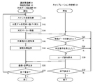
- FIG. 7 is a flowchart showing a processing procedure in which the information processing apparatus 10 according to the present embodiment determines the necessary timing of calibration while performing information processing such as a game.
- the flow on the left is a procedure in which the tracking processing unit 54, the information processing unit 62, and the output data generation unit 66 mainly perform main information processing such as a game
- the flow on the right is a calibration determination unit 64. Is the procedure of the process of determining the timing which needs calibration in parallel to it. The latter is performed in a state in which the user is not aware of the main information processing such as a game, that is, in the background.
- the photographed image acquisition unit 52 requests the imaging device 12 to start photographing, and the stereo transmitted according to the request.
- the tracking processing unit 54 acquires image data (S10).
- the corresponding marker identification unit 58 of the tracking processing unit 54 performs correction to align the vertical position of the acquired stereo image, based on the data representing the positional deviation ⁇ y in the vertical direction stored in the correction data storage unit 56 ( S12).
- the image of the corresponding marker in both is detected (S14).
- the corresponding marker specifying unit 58 provides the position information acquisition unit 60 and the calibration determination unit 64 of the tracking processing unit 54 with the position coordinates of the image of the corresponding marker.
- the position information acquisition unit 60 calculates the distance from the imaging plane of the marker from the difference in the position of the image of the corresponding marker in the lateral direction, and acquires information on the position and orientation of the target (S16).
- the information processing unit 62 causes the information processing such as a game to progress (S18), causes the output data generation unit 66 to generate output data such as an image, and causes the HMD 18 or the like to output the output data (S20).
- the calibration determination unit 64 acquires the position coordinates of the image of the corresponding marker provided from the corresponding marker identification unit 58, first, was position data effective to determine the necessity of calibration obtained? It is determined whether or not it is (S24).
- "effective position data” is position data having sufficient reliability to determine the need for calibration.
- the calibration determination unit 64 determines that calibration is necessary when the vertical displacement of the image of the corresponding marker in the stereo image exceeds a predetermined threshold.
- the determination process is performed using only the position coordinates of the marker detected from, for example, a stereo image of one frame, it is determined that it is necessary at a timing where calibration is not originally necessary due to a temporary error of the position coordinates. It is conceivable that As described above, it is desirable to scrutinize the validity of the position data that is the source of the determination so as not to excessively determine the timing at which the calibration is necessary and to increase the burden on the user.
- the output data generation unit 66 generates image data for notification and outputs it from the HMD 18 or the like (S20). The above processing is repeated for each frame of a moving image captured by the imaging device 12 (N in S22 and N in S32), and when the user requests the end of the information processing via the input device 14 or the game ends, etc. All processing ends (Y in S22 and Y in S32).
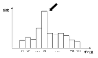
- FIG. 8 is a view for explaining an example of a method of determining whether or not valid position data has been obtained in S24 of FIG.
- the validity of the data is confirmed by accumulating the longitudinal displacement amount of the image of the corresponding marker for a certain period. Specifically, every time the data of the position coordinate of the corresponding marker is supplied from the corresponding marker identifying unit 58, the difference in the vertical direction is defined as the "displacement amount", and the frequency is counted for each deviation amount. As shown in FIG. 4, when five markers appear in each of the stereo images, the frequency of one of the deviation amounts is added a total of five times per frame.
- a histogram of “frequency” with respect to “displacement amount” grows. Then, as indicated by the arrows, the shift amount "Y5" which is clearly superior to the other from the viewpoint of frequency is used as valid position data to determine the necessity of calibration. For example, the deviation amount at which the frequency first exceeds the predetermined threshold value, the deviation amount at which the highest frequency is obtained when the predetermined time has elapsed from the start of data accumulation, the highest frequency at the point when the frequency distribution converges The obtained amount of deviation or the like is referred to as “a significant amount of deviation”. It may be determined by performing statistical processing using a standard deviation or the like.
- the next histogram is formed, discarding the previous histogram and counting the frequency from zero.
- the previous result may be included at a certain rate by adding the frequency after that to the frequency of each shift amount of the previous histogram multiplied by a predetermined rate less than 1.
- the frequency of addition may be weighted according to the situation when the corresponding marker identification unit 58 acquires the position coordinates of the marker. For example, when the image of the marker in the image is small, it is considered that the position coordinate is likely to include an error because the distance from the imaging plane to the marker is long or a part of the marker is out of view.
- weighting may be performed such that the value of the frequency of addition at one time decreases as the marker image decreases.
- the image when there is a light emitter other than a marker such as illumination or a display of a terminal in the field of view, the image may be erroneously recognized as a marker.
- the number of marker images when one object is equipped with a plurality of markers, the number of marker images may decrease depending on the orientation of the object. As the number of marker images decreases, the amount of information that it represents decreases, which makes it easier to misidentify the marker correspondence.
- weighting may be performed so that the value of the frequency to be added at one time becomes small also at these times.
- any event that affects the position coordinate of the marker or the identification accuracy of the correspondence relationship may be used for weighting the addition frequency.
- the histogram can be formed with higher accuracy, and the reliability of the amount of deviation used for determining the necessity of calibration is improved.
- the corresponding marker specifying unit 58 provides the calibration determination unit 64 with various data used for weighting, together with data of position coordinates.
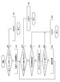
- FIG. 9 is a flowchart showing, as an example of such an embodiment, a processing procedure for confirming the validity of position data when the number of marker images in an image is used.
- the whole process corresponds to the process of S24 in FIG. 7, and the initial stage is a stage prior to newly starting storage of data of position coordinates, such as immediately after valid position data is obtained.
- the calibration determination unit 64 acquires information related to the number of marker images in the image from the corresponding marker identification unit 58 together with the data of the position coordinates.
- data accumulation of position coordinates is started (S44).
- Data accumulation of position coordinates is, for example, the formation of the histogram shown in FIG.
- the larger the number of marker images the lower the possibility of misidentification of the correspondence in the corresponding marker identification unit 58. Therefore, by starting accumulation of data triggered by that, the direction of the object changes in the subsequent accumulation period, etc., and even if the number of images decreases somewhat, the reliability of the data during accumulation is large. It is less likely to be damaged.
- the process is exited (S56). That is, the data accumulation is stopped and the histogram is discarded. If two or more images are detected in either of the stereo images of the next frame (N in S54), the frequency is added based on the positional deviation of the corresponding marker in the frame (S58).
- frequencies are added based on position coordinate data of subsequent frames (N of S46, N of S50, S52, S54 N, S58). If the dominant shift amount can be determined within a predetermined time (Y in S46), it is determined that valid data is obtained (Y in S24 of FIG. 7), and the process is exited (S48). The shift amount obtained at this time is used to determine the necessity of calibration in S26 of FIG. If a predetermined time elapses (N in S46, Y in S50) or no marker image is obtained (Y in S54), valid data can be obtained before a significant shift amount is obtained. It is determined that there is no (N in S24 of FIG. 7), and the process exits (S56). That is, the data accumulation is stopped and the histogram is discarded.
- the number of marker images used for determination in S40 and S54 is not limited to that illustrated. In addition to the number of marker images, any of the events relating to position coordinate acquisition accuracy may be adopted as the reference for triggering accumulation start and end of position coordinate data, other than the number of marker images. . In addition, whether the distance from the imaging plane of the marker is within a predetermined range, whether the image of the marker is within a predetermined range of the frame, whether the marker is occluded due to the presence of a front object, The start and end of accumulation of data of position coordinates may be determined on the basis of whether the light emission of the marker is reflected in another object or not.
- the calibration determining unit 64 acquires information on the tracking accuracy and the tracking situation from the tracking processing unit 54.
- the start and end of accumulation of data of position coordinates may be determined based on that.
- the operation of the calibration determination unit 64 may be stopped.
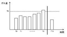
- FIG. 10 is a diagram for explaining the relationship between the effective shift amount acquired as described above and the process of determining the necessity of calibration.
- the horizontal axis represents the elapsed time
- the vertical axis represents the amounts of shift acquired at timings T0, T1,...
- the calibration determination unit 64 compares it with a predetermined threshold value Th. Then, at timing T6 when the deviation amount exceeds the threshold value, it is determined that calibration is necessary, and the user is notified.
- the threshold value Th may be stored inside the information processing apparatus 10 as the optimum value acquired in advance by experiment or the like, or may be read out from the application to be executed.
- the user activates the function of the calibration unit 68 at the timing according to his / her convenience.
- this timing is represented by a thick line.
- the calibration unit 68 acquires the positional deviation ⁇ y in the vertical direction of the stereo image strictly by block matching or the like, and stores the data representing it in the correction data storage unit 56 again.
- the tracking processing unit 54 detects an image of a marker for tracking an object, the stereo image is correctly aligned.
- the effective shift amount acquired next by the calibration determination unit 64 at the timing of T ′ 0 becomes equal to or less than the threshold value Th, and it is determined that the calibration is unnecessary. If the user does not perform calibration even though the user is notified of the necessity of calibration at timing T6, the state where the deviation amount exceeds the threshold Th continues, so the notification is also continued. . Even in this state, the user can continue information processing such as a game. At this time, even if the processing result is affected by the positional deviation, the user can recognize the cause, so that the information processing apparatus and the application can not be evaluated inappropriately or the user can be prevented from feeling stress. .
- camera calibration is performed using the amount of positional deviation in the vertical direction of the image of the marker obtained in the middle of the tracking process. Monitor the need for Then, the user is notified when the need arises and the user is urged to execute the calibration process.
- information processing system 10 information processing apparatus 12 imaging apparatus 14 input device 16 flat panel display 18 HMD 50 input information acquisition unit 52 captured image acquisition unit 54 tracking processing unit 54 correction data storage unit 58 Corresponding marker identification unit, 60 position information acquisition unit, 62 information processing unit, 64 calibration determination unit, 66 output data generation unit, 68 calibration unit, 110a luminescence marker.
- the present invention is applicable to a computer that processes various electronic contents, a display device, a game device, an information processing device, an image processing device, and a system including them.
Landscapes
- Engineering & Computer Science (AREA)
- Multimedia (AREA)
- Physics & Mathematics (AREA)
- Theoretical Computer Science (AREA)
- Human Computer Interaction (AREA)
- General Physics & Mathematics (AREA)
- General Engineering & Computer Science (AREA)
- Signal Processing (AREA)
- Computer Vision & Pattern Recognition (AREA)
- Electromagnetism (AREA)
- Remote Sensing (AREA)
- Radar, Positioning & Navigation (AREA)
- General Health & Medical Sciences (AREA)
- Biomedical Technology (AREA)
- Health & Medical Sciences (AREA)
- User Interface Of Digital Computer (AREA)
- Length Measuring Devices By Optical Means (AREA)
- Position Input By Displaying (AREA)
- Testing, Inspecting, Measuring Of Stereoscopic Televisions And Televisions (AREA)
- Measurement Of Optical Distance (AREA)
Abstract
An information processing device 10 implements in an information processing unit 62 information processing for a game, for example, on the basis of a user operation received by an input information acquisition unit 50 and a stereo-camera image-pickup image, for example, which was acquired by an image-pickup image acquisition unit 52, and outputs the results to a display device from an output data generation unit 66. At that time, a tracking processing unit 54 detects the image of a corresponding marker from the stereo image, and on the basis of the parallax thereof, acquires position information of the target. A calibration determination unit 64 determines the need for camera calibration on the basis of a position misalignment in the vertical direction of the detected image of the marker, and makes a request to the output data generation unit 66 to notify a user.
Description
本発明は、撮影画像における対象物の検出を伴う情報処理技術に関する。
The present invention relates to an information processing technique that involves detection of an object in a captured image.
ユーザの体やマーカーをカメラで撮影し、その像の領域を別の画像で置換してディスプレイに表示するゲームが知られている(例えば、特許文献1参照)。また、カメラで撮影された口や手の動きをアプリケーションの操作指示として受け取るユーザインタフェースシステムも知られている。このように、実世界を撮影しその動きに反応する仮想世界を表示させたり、何らかの情報処理を行ったりする技術は、携帯端末からレジャー施設まで、その規模によらず幅広い分野で利用されている。
There is known a game in which a user's body or marker is photographed by a camera, and the image area is replaced with another image and displayed on a display (see, for example, Patent Document 1). There is also known a user interface system that receives the movement of a mouth or hand photographed by a camera as an operation instruction of an application. As described above, the technology for photographing the real world and displaying the virtual world that responds to the movement, and performing some information processing, is used in a wide range of fields, regardless of the scale, from portable terminals to leisure facilities. .
上記のような技術において、撮影画像から実世界に係る情報をいかに正確に取得するかは常に重要な課題である。例えば、撮像環境の変化や撮像装置の経年変化などによって各種撮影パラメータが変化した場合、情報の取得精度が低下する可能性がある。しかしながらこのような内部パラメータの変化は一般的には不可視の領域であり、ユーザには認識しづらい。その結果ユーザは、装置のパフォーマンスの低下に不満を抱きつつそのまま使用しつづける、という状況にもなり得る。処理開始前などに定期的にキャリブレーションの実施をユーザに促すことで最適条件を得ることも考えられるが、ユーザの負担が大きくなる。
In the above-described techniques, it is always an important issue how to accurately acquire information on the real world from a photographed image. For example, when various imaging parameters change due to a change in an imaging environment, a secular change of an imaging apparatus, or the like, there is a possibility that the acquisition accuracy of information may be lowered. However, such changes in internal parameters are generally invisible regions and difficult for the user to recognize. As a result, the user may be dissatisfied with the degradation of the performance of the device and continue using it as it is. Although it may be considered to obtain the optimum condition by periodically prompting the user to carry out calibration before the start of processing, etc., the burden on the user is increased.
本発明はこうした課題に鑑みてなされたものであり、その目的は、撮影画像を利用した対象物の追跡を伴う情報処理の精度を、ユーザの手間を少なく容易に維持できる技術を提供することにある。
The present invention has been made in view of these problems, and an object thereof is to provide a technology capable of easily maintaining the accuracy of information processing involving tracking of an object using a captured image with less trouble for the user. is there.
本発明のある態様は情報処理装置に関する。この情報処理装置は、ステレオカメラが撮影した画像から対象物の位置情報を取得し情報処理を行う情報処理装置であって、当該ステレオカメラが左右の視点から撮影したステレオ画像から対象物の像を検出する対象物検出部と、当該対象物の像の検出結果に基づき、ステレオ画像の上下方向の位置ずれ量を監視し、当該位置ずれ量が所定の条件を満たしたときカメラキャリブレーションが必要であると判定するキャリブレーション判定部と、カメラキャリブレーションが必要と判定された際、その旨の情報を出力する出力データ生成部と、を備えることを特徴とする。
One embodiment of the present invention relates to an information processing apparatus. The information processing apparatus is an information processing apparatus that acquires position information of an object from an image captured by a stereo camera and performs information processing, and the image of the object is acquired from stereo images captured by the stereo camera from left and right viewpoints. The amount of positional deviation in the vertical direction of the stereo image is monitored based on the object detection unit to be detected and the detection result of the image of the relevant object, and camera calibration is necessary when the positional deviation amount satisfies a predetermined condition It is characterized by comprising a calibration determination unit that determines that there is an output data generation unit that outputs information to that effect when it is determined that camera calibration is necessary.
本発明の別の態様は情報処理方法に関する。この情報処理方法は、ステレオカメラが撮影した画像から対象物の位置情報を取得し情報処理を行う情報処理装置が行う情報処理方法であって、ステレオカメラが左右の視点から撮影したステレオ画像から対象物の像を検出するステップと、当該対象物の像の検出結果に基づき、ステレオ画像の上下方向の位置ずれ量を監視し、当該位置ずれ量が所定の条件を満たしたときカメラキャリブレーションが必要であると判定するステップと、カメラキャリブレーションが必要と判定された際、その旨の情報を出力するステップと、を含むことを特徴とする。
Another aspect of the present invention relates to an information processing method. This information processing method is an information processing method performed by an information processing apparatus that acquires position information of an object from an image captured by a stereo camera and performs information processing, and the target is a stereo image captured by a stereo camera from left and right viewpoints The amount of positional deviation in the vertical direction of the stereo image is monitored based on the step of detecting the image of the object and the detection result of the image of the object, and camera calibration is required when the amount of positional deviation satisfies a predetermined condition And a step of outputting information to that effect when it is determined that camera calibration is necessary.
なお、以上の構成要素の任意の組合せ、本発明の表現を方法、装置、システム、コンピュータプログラム、コンピュータプログラムを記録した記録媒体などの間で変換したものもまた、本発明の態様として有効である。
In addition, any combination of the above-described components, and one obtained by converting the expression of the present invention between a method, an apparatus, a system, a computer program, a recording medium recording a computer program, etc. are also effective as an embodiment of the present invention. .
本発明によると、撮影画像を利用した情報処理の精度を容易に維持できる。
According to the present invention, it is possible to easily maintain the accuracy of information processing using a photographed image.
図1は本実施の形態を適用できる情報処理システムの構成例を示す。情報処理システム8は、対象物を撮影する撮像装置12、撮影した画像に基づき情報処理を行う情報処理装置10、情報処理の結果として得られた画像を表示する平板型ディスプレイ16およびヘッドマウントディスプレイ(以下、「HMD」と呼ぶ)18、ユーザが操作する入力装置14を含む。
FIG. 1 shows a configuration example of an information processing system to which the present embodiment can be applied. The information processing system 8 includes an imaging device 12 for capturing an object, an information processing device 10 for performing information processing based on the captured image, a flat display 16 for displaying an image obtained as a result of the information processing, and a head mounted display (Hereinafter referred to as "HMD") 18 includes an input device 14 operated by the user.
情報処理装置10と、撮像装置12、入力装置14、平板型ディスプレイ16、HMD18とは、有線ケーブルで接続されても、Bluetooth(登録商標)など既知の無線通信技術により接続されてもよい。また情報処理装置10が実施する情報処理によっては、入力装置14、平板型ディスプレイ16、HMD18は選択的に導入してもよい。またこれらの装置の外観形状は図示するものに限らない。さらにこれらのうち2つ以上の装置を一体的に備えた装置としてもよい。例えば情報処理装置10、入力装置14、平板型ディスプレイ16を、それらを備えた携帯端末などで実現してもよい。
The information processing device 10, the imaging device 12, the input device 14, the flat panel display 16, and the HMD 18 may be connected by a wired cable or may be connected by a known wireless communication technology such as Bluetooth (registered trademark). Further, depending on information processing performed by the information processing apparatus 10, the input device 14, the flat panel display 16, and the HMD 18 may be selectively introduced. Moreover, the external appearance shape of these apparatuses is not restricted to what is shown in figure. Furthermore, two or more of these devices may be integrally provided. For example, the information processing apparatus 10, the input device 14, and the flat panel display 16 may be realized by a portable terminal or the like provided with them.
撮像装置12は、ユーザなどの対象物を所定のフレームレートで撮影するカメラと、その出力信号にデモザイク処理など一般的な処理を施すことにより撮影画像の出力データを生成し、情報処理装置10に送出する機構とを有する。カメラはCCD(Charge Coupled Device)センサやCMOS(Complementary Metal Oxide Semiconductor)センサなど、一般的な可視光センサを既知の間隔で左右に配置したステレオカメラである。
The imaging device 12 generates output data of a captured image by performing general processing such as demosaicing processing on a camera that captures an object such as a user at a predetermined frame rate, and generates output data of the captured image. And a sending mechanism. The camera is a stereo camera in which general visible light sensors such as a charge coupled device (CCD) sensor and a complementary metal oxide semiconductor (CMOS) sensor are disposed at right and left at known intervals.
情報処理装置10は、撮像装置12から送信されたデータを用いて必要な情報処理を行い、画像や音声などの出力データを生成する。ここで情報処理装置10が行う処理の内容は特に限定されず、ユーザが求める機能やアプリケーションの内容などによって適宜決定してよい。例えば、撮影画像に対し追跡処理を施すことにより、対象物であるユーザの動作を反映させたキャラクタが登場するゲームを進捗させたり、ユーザの動きをコマンド入力に変換して情報処理を行ったりする。
The information processing apparatus 10 performs necessary information processing using data transmitted from the imaging apparatus 12 and generates output data such as an image and a sound. Here, the content of the process performed by the information processing apparatus 10 is not particularly limited, and may be determined as appropriate depending on the function required by the user or the content of the application. For example, by performing tracking processing on a captured image, a game in which a character reflecting the user's action as an object appears is made to progress, or the user's action is converted into a command input to perform information processing .
このとき入力装置14に設けたマーカーを利用して入力装置14の動きを取得してもよい。またHMD18の外面に設けた複数のマーカーを追跡することにより、HMD18を装着したユーザの頭部の位置や姿勢を特定し、それに対応して動く視点から見た仮想世界をHMD18に表示させてもよい。情報処理装置10が生成した出力データは、HMD18および平板型ディスプレイ16の少なくとも一方に送信される。
At this time, the movement of the input device 14 may be acquired using a marker provided on the input device 14. Also, by tracking a plurality of markers provided on the outer surface of the HMD 18, the position and posture of the head of the user wearing the HMD 18 can be specified, and the virtual world seen from the viewpoint that moves correspondingly can be displayed on the HMD 18 Good. The output data generated by the information processing apparatus 10 is transmitted to at least one of the HMD 18 and the flat panel display 16.
HMD18は、ユーザが頭に装着することによりその眼前に位置する有機ELパネルなどの表示パネルに画像を表示する表示装置である。例えば左右の視点から見た視差画像を生成し、表示画面を2分割してなる左右の領域にそれぞれ表示させることにより、画像を立体視させてもよい。ただし本実施の形態をこれに限る主旨ではなく、表示画面全体に1つの画像を表示させてもよい。HMD18はさらに、ユーザの耳に対応する位置に音声を出力するスピーカーやイヤホンを内蔵していてもよい。
The HMD 18 is a display device that displays an image on a display panel such as an organic EL panel positioned in front of the user when the user wears the head. For example, the images may be stereoscopically viewed by generating parallax images viewed from the left and right viewpoints and displaying them on the left and right areas formed by dividing the display screen. However, the present embodiment is not limited to this, and one image may be displayed on the entire display screen. The HMD 18 may further include a speaker or an earphone that outputs sound at a position corresponding to the user's ear.
平板型ディスプレイ16は、2次元の画像を出力するディスプレイおよび音声を出力するスピーカーを有するテレビでよく、例えば液晶テレビ、有機ELテレビ、プラズマテレビ、PCディスプレイ等である。あるいはタブレット端末や携帯端末のディスプレイおよびスピーカーであってもよい。入力装置14は、ユーザが操作することにより、処理の開始、終了、機能の選択、各種コマンド入力などの要求を受け付け、情報処理装置10に電気信号として供給する。
The flat panel display 16 may be a television having a display for outputting a two-dimensional image and a speaker for outputting an audio, such as a liquid crystal television, an organic EL television, a plasma television, a PC display or the like. Alternatively, it may be a display and a speaker of a tablet terminal or a portable terminal. The input device 14 receives requests such as start and end of processing, selection of functions, and input of various commands by user operation, and supplies the information processing device 10 as an electric signal.
入力装置14は、ゲームコントローラ、キーボード、マウス、ジョイスティック、平板型ディスプレイ16の表示画面上に設けたタッチパッドなど、一般的な入力装置のいずれか、またはそれらの組み合わせによって実現してよい。入力装置14はさらに、所定の色で発光する素子またはその集合からなる発光マーカーを備えていてもよい。この場合、情報処理装置10が撮影画像を用いてマーカーの動きを追跡することにより、入力装置14自体の動きをユーザ操作とすることができる。なお入力装置14を、発光マーカーとそれを把持する機構のみで構成してもよい。
The input device 14 may be realized by any one or a combination of general input devices such as a game controller, a keyboard, a mouse, a joystick, a touch pad provided on the display screen of the flat panel display 16, and the like. The input device 14 may further include a light emission marker made up of elements emitting light of a predetermined color or a set thereof. In this case, when the information processing apparatus 10 tracks the movement of the marker using the captured image, the movement of the input device 14 can be used as the user operation. Note that the input device 14 may be configured only with a light emission marker and a mechanism for gripping the same.
図2は情報処理装置10の内部回路構成を示している。情報処理装置10は、CPU(Central Processing Unit)22、GPU(Graphics Processing Unit)24、メインメモリ26を含む。これらの各部は、バス30を介して相互に接続されている。バス30にはさらに入出力インターフェース28が接続されている。入出力インターフェース28には、USBやIEEE1394などの周辺機器インターフェースや、有線又は無線LANのネットワークインターフェースからなる通信部32、ハードディスクドライブや不揮発性メモリなどの記憶部34、平板型ディスプレイ16やHMD18へデータを出力する出力部36、撮像装置12や入力装置14からデータを入力する入力部38、磁気ディスク、光ディスクまたは半導体メモリなどのリムーバブル記録媒体を駆動する記録媒体駆動部40が接続される。
FIG. 2 shows the internal circuit configuration of the information processing apparatus 10. The information processing apparatus 10 includes a central processing unit (CPU) 22, a graphics processing unit (GPU) 24, and a main memory 26. These units are connected to one another via a bus 30. An input / output interface 28 is further connected to the bus 30. The I / O interface 28 includes a peripheral device interface such as USB or IEEE 1394, a communication unit 32 including a wired or wireless LAN network interface, a storage unit 34 such as a hard disk drive or nonvolatile memory, data to the flat panel display 16 or the HMD 18 An output unit 36 for outputting the data, an input unit 38 for inputting data from the imaging device 12 and the input device 14, and a recording medium drive unit 40 for driving a removable recording medium such as a magnetic disk, an optical disk or a semiconductor memory are connected.
CPU22は、記憶部34に記憶されているオペレーティングシステムを実行することにより情報処理装置10の全体を制御する。CPU22はまた、リムーバブル記録媒体から読み出されてメインメモリ26にロードされた、あるいは通信部32を介してダウンロードされた各種プログラムを実行する。GPU24は、ジオメトリエンジンの機能とレンダリングプロセッサの機能とを有し、CPU22からの描画命令に従って描画処理を行い、表示画像を図示しないフレームバッファに格納する。そしてフレームバッファに格納された表示画像をビデオ信号に変換して出力部36に出力する。メインメモリ26はRAM(Random Access Memory)により構成され、処理に必要なプログラムやデータを記憶する。
The CPU 22 controls the entire information processing apparatus 10 by executing the operating system stored in the storage unit 34. The CPU 22 also executes various programs read from the removable storage medium and loaded into the main memory 26 or downloaded via the communication unit 32. The GPU 24 has a function of a geometry engine and a function of a rendering processor, performs drawing processing according to a drawing command from the CPU 22, and stores a display image in a frame buffer (not shown). Then, the display image stored in the frame buffer is converted into a video signal and output to the output unit 36. The main memory 26 is configured by a RAM (Random Access Memory), and stores programs and data necessary for processing.
図3はHMD18の外観形状の例を示している。この例においてHMD18は、出力機構部102および装着機構部104で構成される。装着機構部104は、ユーザが被ることにより頭部を一周し装置の固定を実現する装着バンド106を含む。装着バンド106は各ユーザの頭囲に合わせて長さの調節が可能な素材または構造とする。例えばゴムなどの弾性体としてもよいし、バックルや歯車などを利用してもよい。
FIG. 3 shows an example of the appearance of the HMD 18. In this example, the HMD 18 includes an output mechanism unit 102 and a mounting mechanism unit 104. The mounting mechanism unit 104 includes a mounting band 106 that turns around the head and achieves fixation of the device by being worn by the user. The mounting band 106 is made of a material or a structure whose length can be adjusted to fit the head circumference of each user. For example, an elastic body such as rubber may be used, or a buckle or a gear may be used.
出力機構部102は、HMD18をユーザが装着した状態において左右の目を覆うような形状の筐体108を含み、内部には装着時に目に正対するように表示パネルを備える。そして筐体108の外面には、発光マーカー110a、110b、110c、110d、110eなどを設ける。発光マーカーの数や配置は特に限定されないが、本実施の形態では出力機構部102の筐体前面の4隅および中央に設ける。さらに、装着バンド106後方の両側面にも発光マーカー110f、110gを設けてよい。なお発光マーカー110d、110eは出力機構部102の下側、発光マーカー110f、110gは装着バンド106の外側にあり、図3の視点からは本来は見えないため、外周を点線で表している。
The output mechanism section 102 includes a housing 108 shaped to cover the left and right eyes when the HMD 18 is worn by the user, and the display mechanism internally includes a display panel so as to face the eyes when worn. Then, on the outer surface of the housing 108, light emitting markers 110a, 110b, 110c, 110d, 110e and the like are provided. Although the number and arrangement of the light emission markers are not particularly limited, they are provided at the four corners and the center of the front surface of the case of the output mechanism section 102 in the present embodiment. Furthermore, the light emission markers 110 f and 110 g may be provided on both sides behind the mounting band 106. The light emitting markers 110d and 110e are on the lower side of the output mechanism section 102, and the light emitting markers 110f and 110g are on the outside of the mounting band 106 and can not be originally seen from the viewpoint of FIG.
本実施の形態の情報処理装置10は、HMD18などの対象物に設けた発光マーカーの像を撮影画像から検出し、それに基づき対象物の位置や姿勢を取得することを基本とする。これにより上述のように、ユーザ自身の位置や姿勢を取得し、それに応じた視点からの仮想世界をHMD18に表示させるなど、ユーザの動きや位置に応じた情報処理を行う。ここで発光マーカーは、HMD18に設けたものに限らず、入力装置14に設けたものやユーザの体に直接、取り付けたものなどでもよい。
The information processing apparatus 10 according to the present embodiment is basically based on detecting an image of a light emission marker provided on an object such as the HMD 18 from a captured image, and acquiring the position and posture of the object based thereon. Thereby, as described above, the user's own position and posture are acquired, and the virtual world from the viewpoint according to it is displayed on the HMD 18, and information processing is performed according to the user's movement and position. Here, the light emission marker is not limited to the one provided in the HMD 18, but may be one provided in the input device 14 or one directly attached to the user's body.
すなわち情報処理の内容に応じて、追跡したい対象物に発光マーカーが装着されていればよい。人の頭部の位置や姿勢を、HMD18を用いて追跡する、という態様でない場合、表示装置はHMD18に限らなくてよい。またマーカーは、所定の色や形状を有し、撮影空間にある他の物からの識別が可能な物や図形であればよく、発光体に限らない。
That is, according to the content of the information processing, the light emission marker may be attached to the object to be tracked. The display device is not limited to the HMD 18 in the case where the position and posture of the human head are not tracked using the HMD 18. The marker may be any object or figure that has a predetermined color or shape and can be distinguished from other objects in the imaging space, and is not limited to the light emitter.
図4は、撮像装置12が撮影した画像を用いて対象物を追跡する手法を説明するための図である。上述の通り撮像装置12は、2つのカメラを既知の間隔で左右に配置したステレオカメラで構成される。当該ステレオカメラで左右の視点から撮影した一対の画像(ステレオ画像)には、カメラの間隔と被写体のカメラからの距離に依存して、画像の横方向に視差が生じる。図示するステレオ画像120a、120bには、図3で示したHMD18のように、網掛けで示した5つのマーカーの像が、左視点からの画像120aにおいては右寄りに、右視点からの画像120bにおいては左よりに、それぞれ写っている。
FIG. 4 is a diagram for describing a method of tracking an object using an image captured by the imaging device 12. As described above, the imaging device 12 is configured of a stereo camera in which two cameras are disposed at right and left at known intervals. In a pair of images (stereo images) captured from left and right viewpoints with the stereo camera, parallax occurs in the lateral direction of the image depending on the distance between the cameras and the distance from the camera of the subject. In the illustrated stereo images 120a and 120b, as in the HMD 18 shown in FIG. 3, the images of the five markers shown by hatching are in the image 120a from the left viewpoint and to the right in the image 120b from the right viewpoint. From the left.
これらの像を色、形状、配置などに基づき検出し、両画像で対応するマーカーの像の横方向の位置座標の差分(例えばx_l-x_r)を求めれば、それに基づき撮像面から当該マーカーまでの距離を取得できる。ステレオ画像における像の横方向の位置の差分に基づき撮像面からの距離を算出する手法は、三角測量の原理に基づく一般的なものである。そして算出した距離に基づき、画像平面でのマーカーの位置座標を実空間に逆射影することにより、実空間でのマーカーの位置、ひいては対象物の位置を特定できる。
If these images are detected based on color, shape, arrangement, etc., and the difference (e.g., x_l_x_r) of the position coordinates in the lateral direction of the images of the corresponding markers in both images is obtained, You can get the distance. The method of calculating the distance from the imaging plane based on the difference in the lateral position of the image in the stereo image is a general one based on the principle of triangulation. Then, based on the calculated distance, the position of the marker in the real space, that is, the position of the object can be specified by back-projecting the position coordinates of the marker on the image plane to the real space.
撮像装置12を構成する2つのカメラの光軸が平行で、縦方向の位置ずれもない状態であれば、ステレオ画像120a、120bにおける同一のマーカーの像の縦方向の位置(例えばy_lおよびy_r)は一致する。このように縦方向の位置が一致していれば、両画像における対応するマーカーの像の特定は容易である。しかし実際には、製造時の組み立て精度などによって微妙な光軸ずれが発生し得る。
If the optical axes of the two cameras constituting the imaging device 12 are parallel and there is no positional deviation in the longitudinal direction, the longitudinal positions of the images of the same marker in the stereo images 120a and 120b (for example, y_l and y_r) Matches. As described above, if the vertical positions coincide with each other, it is easy to specify the image of the corresponding marker in both images. However, in practice, a slight deviation of the optical axis may occur due to the assembly accuracy at the time of manufacture.
図5は左右のカメラの光軸(特にピッチ角)または縦方向の位置がずれているときのステレオ画像を示している。この例では、左視点からの画像120aにおけるマーカーの像の縦方向の位置(例えばy_l)が、右視点からの画像120bにおける対応するマーカーの像の位置(例えばy_r)よりΔyだけ上にある。この状態で、対応するマーカーの像は両画像の同じ行にあるという原則に従い対応づけを行うと、Δyが10画素程度の差であっても対応を誤認識してしまう可能性が出てくる。そのため正確な視差が得られず、最終的には対象物の追跡精度が十分に得られないことがあり得る。
FIG. 5 shows a stereo image when the optical axis (especially pitch angle) of the left and right cameras or the position in the longitudinal direction is shifted. In this example, the vertical position (eg, y_l) of the image of the marker in the image 120a from the left viewpoint is above the position (eg, y_r) of the image of the corresponding marker in the image 120b from the right viewpoint. Under this condition, if correspondence is made according to the principle that the images of the corresponding markers are in the same row of both images, there is a possibility that the correspondence may be misrecognized even if Δy is a difference of about 10 pixels. . Therefore, accurate parallax may not be obtained, and eventually, the tracking accuracy of the object may not be sufficiently obtained.
そのため製造された段階で撮像装置12個々の状態を確認し、縦方向の位置ずれΔyを表すパラメータを不揮発性メモリなどに記録しておく。運用時には、情報処理装置10側で当該パラメータを読み出し、撮像装置12が撮影したステレオ画像のうちどちらかを、仮想的に画像平面上で縦方向にΔyだけずらすことにより、画像間で縦方向の位置を揃える。図5の例では、右視点からの画像120bを上方にΔyだけ移動させることにより、点線で枠を示した補正画像122を生成している。
Therefore, the state of each imaging device 12 is confirmed at the stage of manufacture, and parameters representing the positional deviation Δy in the vertical direction are recorded in a non-volatile memory or the like. At the time of operation, the information processing apparatus 10 reads the parameter and virtually shifts one of the stereo images captured by the imaging apparatus 12 by Δy on the image plane virtually, so that the images can be vertically extracted. Align the position. In the example of FIG. 5, the corrected image 122 in which a frame is indicated by a dotted line is generated by moving the image 120 b from the right viewpoint upward by Δy.
そして左視点からの画像120aと補正画像122とを比較すれば、対応するマーカーの像を縦方向の位置に基づき容易に特定できる。しかしながら、撮像装置12が出荷された後であっても、運用時に装置内部で発生する熱、落下など外部から加えられた衝撃、部品の経年変化など、様々な要因で位置ずれΔyが変化し得る。このため処理精度を維持するには、ユーザは独自にキャリブレーションし直し、位置ずれΔyの設定値を更新することが望ましい。
Then, by comparing the image 120a from the left viewpoint with the corrected image 122, the image of the corresponding marker can be easily identified based on the position in the vertical direction. However, even after the imaging device 12 is shipped, the positional deviation Δy may change due to various factors such as heat generated inside the device during operation, an externally applied impact such as falling, and aging of parts. . Therefore, in order to maintain the processing accuracy, it is desirable that the user recalibrate independently and update the setting value of the positional deviation Δy.
しかしその好適なタイミングは使用状況などにもよるため共通ではなく、ユーザ自身が必要性を認識することも難しい。また、運用時に簡易な処理で高速かつ高精度に追跡処理を行うためには、キャリブレーションについてはある程度、厳密に実施することが望ましい。例えば画面全体を対象としてブロックマッチングにより対応点を取得し、詳細なマッチング処理を集約させた結果として位置ずれΔyを求めることが望ましい。また好適には、そのようなブロックマッチングに適した条件や環境で撮影した画像を用いてさらに精度を向上させる。
However, the suitable timing is not common because it also depends on the use situation and the like, and it is also difficult for the user himself to recognize the necessity. In addition, in order to perform tracking processing at high speed and with high accuracy by simple processing at the time of operation, it is desirable to carry out calibration strictly to some extent. For example, it is desirable to obtain corresponding points by block matching for the entire screen and obtain positional deviation Δy as a result of aggregating detailed matching processing. Also, preferably, the accuracy is further improved using an image captured under conditions or environment suitable for such block matching.
このようなキャリブレーション処理を高い頻度で行うように規則づけると、その間、情報処理装置10を利用できなかったり、撮影環境を整える手間が増えたりして、ユーザにストレスを与えることになる。これを回避するためキャリブレーションを行わないでいると、追跡処理の精度が低下して出力結果に影響を及ぼし、装置やアプリケーション自体の性能が、本来よりも低く評価されてしまうこともあり得る。そこで本実施の形態では、キャリブレーション処理が必要なタイミングを情報処理装置10が判断することにより、最低限の手間で追跡精度を維持できるようにする。
If such a calibration process is performed at a high frequency, the information processing apparatus 10 can not be used during that time, and the time required to set up the imaging environment increases, which causes the user to be stressed. If calibration is not performed to avoid this, the accuracy of the tracking process may be degraded to affect the output result, and the performance of the apparatus or application itself may be evaluated lower than originally expected. Therefore, in the present embodiment, the information processing apparatus 10 determines the timing at which the calibration process is necessary, so that the tracking accuracy can be maintained with the minimum amount of time and effort.
図6は情報処理装置10の機能ブロックの構成を示している。図6に示す各機能ブロックは、ハードウェア的には、図2に示したCPU、GPU、メモリなどの構成で実現でき、ソフトウェア的には、記録媒体などからメモリにロードした、データ入力機能、データ保持機能、画像処理機能、入出力機能などの諸機能を発揮するプログラムで実現される。したがって、これらの機能ブロックがハードウェアのみ、ソフトウェアのみ、またはそれらの組合せによっていろいろな形で実現できることは当業者には理解されるところであり、いずれかに限定されるものではない。
FIG. 6 shows the configuration of functional blocks of the information processing apparatus 10. In terms of hardware, each functional block shown in FIG. 6 can be realized by the configuration of the CPU, GPU, memory, etc. shown in FIG. 2, and in software, it is a data input function loaded into the memory from a recording medium etc. It is realized by a program that exhibits various functions such as a data holding function, an image processing function, and an input / output function. Therefore, it is understood by those skilled in the art that these functional blocks can be realized in various forms by hardware only, software only, or a combination thereof, and is not limited to any of them.
情報処理装置10は、入力装置14からの入力情報を取得する入力情報取得部50、撮像装置12から撮影画像のデータを取得する撮影画像取得部52、マーカーの像に基づき対象物を追跡する追跡処理部54、追跡結果を用いるなどして情報処理を行う情報処理部62、情報処理の結果として表示画像などの出力データを生成する出力データ生成部66、追跡処理と並行してキャリブレーションの必要なタイミングを判定するキャリブレーション判定部64、キャリブレーションを実施するキャリブレーション部68を含む。
The information processing apparatus 10 includes an input information acquisition unit 50 for acquiring input information from the input device 14, a photographed image acquisition unit 52 for acquiring data of a photographed image from the imaging device 12, and tracking for tracking an object based on an image of a marker. The processing unit 54, the information processing unit 62 that performs information processing using tracking results, etc., the output data generation unit 66 that generates output data such as a display image as a result of information processing, the need for calibration in parallel with tracking processing It includes a calibration determination unit 64 that determines the proper timing, and a calibration unit 68 that performs the calibration.
入力情報取得部50は、ユーザ操作の内容を入力装置14から取得する。ここでユーザ操作とは、実行するアプリケーションの選択、処理の開始/終了、コマンド入力など、一般的な情報処理でなされるものでよい。入力情報取得部50は入力装置14から取得した情報を、その内容に応じて撮影画像取得部52、情報処理部62、キャリブレーション部68に供給する。
The input information acquisition unit 50 acquires the content of the user operation from the input device 14. Here, the user operation may be a general information processing such as selection of an application to be executed, start / end of processing, and command input. The input information acquisition unit 50 supplies the information acquired from the input device 14 to the photographed image acquisition unit 52, the information processing unit 62, and the calibration unit 68 according to the contents.
撮影画像取得部52は、撮像装置12が動画撮影して得られる撮影画像のデータを所定のフレームレートで取得する。撮影画像取得部52はさらに、入力情報取得部50が取得したユーザからの処理開始/終了要求に従い、撮像装置12における撮影の開始/終了を制御したり、情報処理部62における処理の結果に応じて、撮像装置12から取得するデータの種類を制御したりしてもよい。
The photographed image acquisition unit 52 acquires data of a photographed image obtained by moving image photographing of the imaging device 12 at a predetermined frame rate. The photographed image acquisition unit 52 further controls the start / end of photographing in the imaging device 12 according to the processing start / end request from the user acquired by the input information acquisition unit 50, or according to the processing result in the information processing unit 62. The type of data acquired from the imaging device 12 may be controlled.
追跡処理部54は、撮影画像に基づきHMD18などの対象物を追跡し、動きや位置を特定する。詳細には追跡処理部54は、対応マーカー特定部58、位置情報取得部60、および補正データ記憶部56を含む。対応マーカー特定部58は、動画撮影された各フレームのステレオ画像のデータを撮影画像取得部52から取得し、両画像から対応するマーカーの像を検出する。そして当該マーカーの像の位置座標を対応づけて、位置情報取得部60およびキャリブレーション判定部64に供給する。
The tracking processing unit 54 tracks an object such as the HMD 18 based on the captured image, and specifies the movement or the position. Specifically, the tracking processing unit 54 includes a corresponding marker specifying unit 58, a position information acquisition unit 60, and a correction data storage unit 56. The corresponding marker specifying unit 58 acquires data of a stereo image of each frame in which a moving image is captured from the captured image acquiring unit 52, and detects an image of a corresponding marker from both images. Then, the position coordinates of the image of the marker are associated and supplied to the position information acquisition unit 60 and the calibration determination unit 64.
ここで「位置座標」は、マーカーの像の有限面積のうち、重心など所定箇所の位置座標を意味する。補正データ記憶部56は、ステレオ画像の縦方向の位置ずれΔyを表すデータが格納され記憶領域である。当該データは、初期状態では、工場出荷時などに取得されたものである。対応マーカー特定部58は、当該データを読み出すことにより、それが表す位置ずれΔyに基づきステレオ画像のどちらかの画像を画像平面上で縦方向にずらし、左右の画像の縦方向の位置を揃えたうえで、対応するマーカーの像を特定する。
Here, "position coordinates" means position coordinates of a predetermined place such as a center of gravity within a finite area of an image of a marker. The correction data storage unit 56 is a storage area in which data representing the positional deviation Δy in the vertical direction of the stereo image is stored. In the initial state, the data is acquired at the time of factory shipment and the like. By reading out the data, the corresponding marker specifying unit 58 vertically shifts either image of the stereo image on the image plane based on the displacement Δy that it represents, and aligns the positions of the left and right images in the vertical direction. And identify the image of the corresponding marker.
位置情報取得部60は、ステレオ画像における、対応するマーカーの像の横方向の位置の差分に基づき、三角測量の原理でマーカー、ひいてはそれが備えられた対象物の位置を特定する。複数のマーカーを用い、それらの位置関係などによって対象物の姿勢も特定してよい。例えば、あらかじめ対象物の3次元モデルを準備しておき、見かけ上のマーカーの位置を3次元モデルに当てはめることにより、対象物の姿勢を求めることができる。
The position information acquisition unit 60 specifies the position of the marker, and hence the object provided with it, based on the principle of triangulation, based on the difference in the lateral position of the image of the corresponding marker in the stereo image. The posture of the object may also be specified by using a plurality of markers and their positional relationship and the like. For example, the posture of the object can be determined by preparing a three-dimensional model of the object in advance and applying the apparent position of the marker to the three-dimensional model.
さらに、対象物が備える加速度センサなど各種センサによる計測値を取得し、撮影画像から得られる位置情報と統合することにより、姿勢等をより詳細に特定してもよい。位置情報取得部60は、取得した対象物の位置や姿勢の情報を情報処理部62に供給する。情報処理部62は、ユーザが指定したゲームなどの情報処理を実施する。この際、対象物の追跡結果を追跡処理部54からフレームごとに取得することにより、対象物の動きを情報処理に反映させる。さらに入力装置14から入力情報取得部50が取得したユーザ操作の内容も反映させてよい。上述のとおり、これらの入力データを用いて情報処理部62が行う情報処理の内容は特に限定されない。
Furthermore, the posture or the like may be specified in more detail by acquiring measurement values by various sensors such as an acceleration sensor included in the object and integrating it with position information obtained from the captured image. The position information acquisition unit 60 supplies the information on the acquired position and orientation of the target to the information processing unit 62. The information processing unit 62 performs information processing such as a game specified by the user. At this time, the movement result of the object is reflected in the information processing by acquiring the tracking result of the object from the tracking processing unit 54 for each frame. Furthermore, the content of the user operation acquired by the input information acquisition unit 50 from the input device 14 may be reflected. As described above, the content of the information processing performed by the information processing unit 62 using these input data is not particularly limited.
キャリブレーション判定部64は、追跡処理部54の対応マーカー特定部58から供給された、対応するマーカーの像の位置座標のうち、縦方向の位置座標の差分に基づき、キャリブレーションが必要なタイミングを判定する。具体的には、補正データ記憶部56に設定されている縦方向の位置ずれΔyに基づき縦方向の位置をそろえた後のステレオ画像において、さらにマーカーの像が縦方向にずれていないかを監視し、しきい値を超えるずれが観測されたら、位置ずれΔyの設定値を更新する必要がある、と判定する。詳細な処理内容については後述する。
The calibration determination unit 64 determines the timing at which calibration is required based on the difference between the position coordinates in the vertical direction among the position coordinates of the image of the corresponding marker supplied from the corresponding marker identification unit 58 of the tracking processing unit 54. judge. Specifically, in the stereo image after aligning the vertical position based on the vertical positional deviation Δy set in the correction data storage unit 56, it is further monitored whether the image of the marker is shifted in the vertical direction. If a deviation exceeding the threshold is observed, it is determined that the set value of the positional deviation Δy needs to be updated. Detailed processing contents will be described later.
出力データ生成部66は、情報処理部62からの要求に従い、情報処理の結果として出力すべき画像や音声のデータを生成する。例えば上述のように、ユーザの頭部の位置や姿勢に対応する視点から見た仮想世界を左右の視差画像とし描画する。この視差画像をHMD18において左右の目の前に表示させたり、仮想世界での音声を出力したりすれば、ユーザはあたかも仮想世界に入り込んだような感覚を得られる。そのほか、追跡結果やユーザ操作を利用して様々な情報処理を実現できることは当業者には理解されるところである。
The output data generation unit 66 generates image and sound data to be output as a result of the information processing in accordance with the request from the information processing unit 62. For example, as described above, the virtual world viewed from the viewpoint corresponding to the position and posture of the head of the user is drawn as the left and right parallax images. If this parallax image is displayed in front of the left and right eyes in the HMD 18 or the sound in the virtual world is output, the user can feel as if it were in the virtual world. Besides, it is understood by those skilled in the art that various information processing can be realized using tracking results and user operations.
出力データ生成部66はまた、キャリブレーションの必要が生じたとキャリブレーション判定部64が判定した際、その旨をユーザに通知するための表示画像を生成する。生成した出力データは、適宜、HMD18や平板型ディスプレイ16に出力することで、画像や音声として出力させる。
When the calibration determination unit 64 determines that the need for calibration has occurred, the output data generation unit 66 also generates a display image for notifying the user of that. The generated output data is appropriately output to the HMD 18 or the flat panel display 16 so as to be output as an image or sound.
キャリブレーション部68は、所定のキャリブレーション処理を実施し、補正データ記憶部56に格納された、位置ずれΔyを表すデータを更新する。キャリブレーション部68の動作は、キャリブレーションの必要性を通知されたユーザが、入力装置14を介して起動させることを基本とする。これに応じてキャリブレーション部68は、例えばステレオ画像の全面をピクセル単位あるいはサブピクセル単位で走査していくことにより対応点を抽出し、その位置座標を比較するなどして位置ずれΔyを正確に取得する。
The calibration unit 68 performs predetermined calibration processing, and updates data representing the positional deviation Δy stored in the correction data storage unit 56. The operation of the calibration unit 68 is based on activation by the user notified of the necessity of calibration via the input device 14. In response to this, the calibration unit 68 extracts corresponding points, for example, by scanning the entire surface of the stereo image in pixel units or sub-pixel units, compares the position coordinates, etc. get.
すなわち、ゲームなどの情報処理において追跡処理部54が対象物を追跡するためにマーカーの像を検出する処理より詳細な情報を取得する。そのため、明るさや被写体などの撮影環境、露光時間などの撮影条件、ゲイン値などの画像処理条件は、ゲームなどの情報処理中とは異なることが多い点に留意する。撮影環境については、最適な状態を準備してもらうように、表示などを用いてユーザに促してもよい。このようにキャリブレーションが求める環境や処理条件が、ゲームなどの通常処理時のものとは異なっていても、本実施の形態ではそのタイミングを装置が判定することにより実施頻度を最小限とし、ユーザの負担を少なく情報処理の精度が維持されるようにする。
That is, in the information processing such as a game, the tracking processing unit 54 acquires more detailed information than the processing of detecting the image of the marker in order to track the object. Therefore, it should be noted that the image processing conditions such as the brightness and the photographing environment of the subject, the photographing conditions such as the exposure time, and the gain value are often different from those in the information processing such as the game. With regard to the shooting environment, the user may be prompted using a display or the like to prepare an optimal state. As described above, even if the environment and processing conditions required by the calibration are different from those at the time of normal processing such as a game, in the present embodiment, the apparatus determines the timing to minimize the frequency of execution and the user To reduce the burden of data processing and maintain the accuracy of information processing.
次に、以上の構成によって実現される情報処理装置10の動作について説明する。図7は、本実施の形態における情報処理装置10が、ゲームなどの情報処理を行いながら、キャリブレーションの必要なタイミングを判定する処理手順を示すフローチャートである。このフローチャートのうち左のフローは、主に追跡処理部54、情報処理部62、出力データ生成部66が、ゲームなど主たる情報処理を実施する手順であり、右のフローは、キャリブレーション判定部64がそれに並行して行う、キャリブレーションが必要なタイミングを判定する処理の手順である。後者はゲームなど主たる情報処理の最中に、ユーザに意識されることのない状態、すなわちバックグラウンドでなされるものである。
Next, the operation of the information processing apparatus 10 realized by the above configuration will be described. FIG. 7 is a flowchart showing a processing procedure in which the information processing apparatus 10 according to the present embodiment determines the necessary timing of calibration while performing information processing such as a game. In the flowchart, the flow on the left is a procedure in which the tracking processing unit 54, the information processing unit 62, and the output data generation unit 66 mainly perform main information processing such as a game, and the flow on the right is a calibration determination unit 64. Is the procedure of the process of determining the timing which needs calibration in parallel to it. The latter is performed in a state in which the user is not aware of the main information processing such as a game, that is, in the background.
まずユーザが入力装置14を用いて、ゲームを選択するなどして処理の開始要求を入力すると、撮影画像取得部52は撮像装置12に撮影の開始を要求し、これに応じて送信されたステレオ画像のデータを追跡処理部54が取得する(S10)。追跡処理部54の対応マーカー特定部58はまず、補正データ記憶部56に格納された、縦方向の位置ずれΔyを表すデータに基づき、取得したステレオ画像の縦方向の位置を合わせる補正を行う(S12)。そのうえで、両者における対応するマーカーの像を検出する(S14)。
First, when the user uses the input device 14 to select a game or the like to input a process start request, the photographed image acquisition unit 52 requests the imaging device 12 to start photographing, and the stereo transmitted according to the request. The tracking processing unit 54 acquires image data (S10). First, the corresponding marker identification unit 58 of the tracking processing unit 54 performs correction to align the vertical position of the acquired stereo image, based on the data representing the positional deviation Δy in the vertical direction stored in the correction data storage unit 56 ( S12). Then, the image of the corresponding marker in both is detected (S14).
補正によって、対応するマーカーの像が縦方向の限定的な範囲内に収まっていることになり、両者の対応づけを容易に行える。対応マーカー特定部58は、対応するマーカーの像の位置座標を追跡処理部54の位置情報取得部60とキャリブレーション判定部64に提供する。位置情報取得部60は、対応するマーカーの像の横方向の位置の差分から、当該マーカーの撮像面からの距離を算出したうえ、対象物の位置や姿勢の情報を取得する(S16)。
As a result of the correction, the image of the corresponding marker is within the limited range in the vertical direction, so that both can be easily associated. The corresponding marker specifying unit 58 provides the position information acquisition unit 60 and the calibration determination unit 64 of the tracking processing unit 54 with the position coordinates of the image of the corresponding marker. The position information acquisition unit 60 calculates the distance from the imaging plane of the marker from the difference in the position of the image of the corresponding marker in the lateral direction, and acquires information on the position and orientation of the target (S16).
情報処理部62はその結果を受けてゲームなどの情報処理を進捗させ(S18)、出力データ生成部66に画像などの出力データを生成させて、HMD18などから出力させる(S20)。一方、キャリブレーション判定部64は、対応マーカー特定部58から提供された、対応するマーカーの像の位置座標を取得したら、まずキャリブレーションの必要性を判定するのに有効な位置データが得られたか否かを判定する(S24)。ここで「有効な位置データ」とは、キャリブレーションの必要性を判定するのに十分な信頼性を有する位置データである。
In response to the result, the information processing unit 62 causes the information processing such as a game to progress (S18), causes the output data generation unit 66 to generate output data such as an image, and causes the HMD 18 or the like to output the output data (S20). On the other hand, if the calibration determination unit 64 acquires the position coordinates of the image of the corresponding marker provided from the corresponding marker identification unit 58, first, was position data effective to determine the necessity of calibration obtained? It is determined whether or not it is (S24). Here, "effective position data" is position data having sufficient reliability to determine the need for calibration.
キャリブレーション判定部64は定性的には、ステレオ画像における対応するマーカーの像の縦方向の位置ずれが所定のしきい値を超えたときに、キャリブレーションの必要があると判定する。しかしながら、例えば1フレーム分のステレオ画像から検出したマーカーの位置座標のみを用いて判定処理を行った場合、位置座標の一時的な誤差により、本来、キャリブレーションの必要ないタイミングで必要と判定してしまうことが考えられる。このようにキャリブレーションが必要なタイミングを余計に判定しユーザの負担を増やすことがないよう、判定の元となる位置データの有効性を精査することが望ましい。
Qualitatively, the calibration determination unit 64 determines that calibration is necessary when the vertical displacement of the image of the corresponding marker in the stereo image exceeds a predetermined threshold. However, when the determination process is performed using only the position coordinates of the marker detected from, for example, a stereo image of one frame, it is determined that it is necessary at a timing where calibration is not originally necessary due to a temporary error of the position coordinates. It is conceivable that As described above, it is desirable to scrutinize the validity of the position data that is the source of the determination so as not to excessively determine the timing at which the calibration is necessary and to increase the burden on the user.
具体的には、(1)追跡処理部54による対象物の追跡処理が精度よく行われていること、(2)十分な量の位置データが収集できたこと、などの観点から位置データの有効性を判断する。具体例は後述する。S24で有効なデータが得られない間は、有効なデータが得られるまで、対応するマーカーの位置情報取得および判定処理を繰り返す(S24のN)。有効な位置データが得られたら(S24のY)、それが表す縦方向の位置のずれをしきい値と比較し、キャリブレーションを必要とする条件を満たしたら(S26のY)、その旨をユーザに通知するよう出力データ生成部66に要求する(S30)。
Specifically, from the viewpoint of (1) accurate tracking of the object by the tracking processing unit 54 and (2) collection of a sufficient amount of positional data, etc. Determine the sex. A specific example will be described later. While valid data can not be obtained in S24, positional information acquisition and determination processing of the corresponding marker is repeated until valid data is obtained (N in S24). If valid position data is obtained (Y in S24), the deviation of the vertical position that it represents is compared with the threshold value, and if the condition that requires calibration is satisfied (Y in S26), The output data generation unit 66 is requested to notify the user (S30).
キャリブレーションを必要とする条件を満たさなかったら、現状の位置ずれΔyの設定値で問題ないとし、再度、有効なデータが得られるまでS24の判定処理を繰り返す(S26のN)。キャリブレーションの必要性をユーザに通知する要求がなされたら、出力データ生成部66は、通知用の画像データを生成しHMD18などから出力させる(S20)。以上の処理を、撮像装置12が撮影する動画のフレーム単位で繰り返し(S22のNおよびS32のN)、ユーザが入力装置14を介して情報処理の終了を要求したりゲームが終了するなどしたら、全ての処理を終了する(S22のYおよびS32のY)。
If the condition requiring calibration is not satisfied, there is no problem with the current setting value of positional deviation Δy, and the determination processing of S24 is repeated again until valid data is obtained (N of S26). When a request for notifying the user of the necessity of calibration is made, the output data generation unit 66 generates image data for notification and outputs it from the HMD 18 or the like (S20). The above processing is repeated for each frame of a moving image captured by the imaging device 12 (N in S22 and N in S32), and when the user requests the end of the information processing via the input device 14 or the game ends, etc. All processing ends (Y in S22 and Y in S32).
図8は図7のS24で、有効な位置データが得られたか否かを判定する手法の一例を説明するための図である。この例では、対応するマーカーの像の縦方向の位置ずれ量を、ある期間、蓄積していくことによりデータの有効性を確認している。具体的には、対応するマーカーの位置座標のデータが対応マーカー特定部58から供給される都度、その縦方向の差分を「ずれ量」とし、ずれ量ごとに頻度をカウントしていく。図4で示したように5つのマーカーがステレオ画像のそれぞれに写っている場合は、1フレームにつき合計5回、いずれかのずれ量の頻度が加算されることになる。
FIG. 8 is a view for explaining an example of a method of determining whether or not valid position data has been obtained in S24 of FIG. In this example, the validity of the data is confirmed by accumulating the longitudinal displacement amount of the image of the corresponding marker for a certain period. Specifically, every time the data of the position coordinate of the corresponding marker is supplied from the corresponding marker identifying unit 58, the difference in the vertical direction is defined as the "displacement amount", and the frequency is counted for each deviation amount. As shown in FIG. 4, when five markers appear in each of the stereo images, the frequency of one of the deviation amounts is added a total of five times per frame.
この処理を繰り返すことにより、図8に示すように「ずれ量」に対する「頻度」のヒストグラムが成長していく。そして矢印で示したように、頻度の観点から他と比べて明らかに優位なずれ量「Y5」を、有効な位置データとしてキャリブレーションの必要性判定に用いる。例えば、頻度が所定のしきい値を最初に超えたずれ量、データ蓄積開始から所定時間経過した時点で最も高い頻度が得られているずれ量、頻度の分布が収束した時点で最も高い頻度が得られているずれ量などを「優位なずれ量」とする。標準偏差などを用いて統計処理を行って決定してもよい。
By repeating this process, as shown in FIG. 8, a histogram of “frequency” with respect to “displacement amount” grows. Then, as indicated by the arrows, the shift amount "Y5" which is clearly superior to the other from the viewpoint of frequency is used as valid position data to determine the necessity of calibration. For example, the deviation amount at which the frequency first exceeds the predetermined threshold value, the deviation amount at which the highest frequency is obtained when the predetermined time has elapsed from the start of data accumulation, the highest frequency at the point when the frequency distribution converges The obtained amount of deviation or the like is referred to as “a significant amount of deviation”. It may be determined by performing statistical processing using a standard deviation or the like.
一旦、優位なずれ量を決定したら、次のヒストグラム形成時には、前のヒストグラムを破棄して頻度を0からカウントし直す。あるいは、前のヒストグラムの各ずれ量の頻度に1未満の所定の割合を乗算したものにさらに以降の頻度を加算していくことにより、ある程度の割合で前の結果が含まれるようにしてもよい。また加算する頻度には、対応マーカー特定部58がマーカーの位置座標を取得したときの状況に応じて重みづけを行ってもよい。例えば、画像中のマーカーの像が小さい場合、撮像面からマーカーまでの距離が遠かったり、マーカーの一部が視野外にあったりして、位置座標に誤差が含まれやすいと考えられる。
Once the dominant offset has been determined, the next histogram is formed, discarding the previous histogram and counting the frequency from zero. Alternatively, the previous result may be included at a certain rate by adding the frequency after that to the frequency of each shift amount of the previous histogram multiplied by a predetermined rate less than 1. . The frequency of addition may be weighted according to the situation when the corresponding marker identification unit 58 acquires the position coordinates of the marker. For example, when the image of the marker in the image is small, it is considered that the position coordinate is likely to include an error because the distance from the imaging plane to the marker is long or a part of the marker is out of view.
したがって、マーカーの像が小さいほど1回に加算する頻度の値が小さくなるように重み付けしてもよい。また視野内に照明や端末のディスプレイなどマーカー以外の発光体がある場合、その像をマーカーと誤認識する可能性がある。さらに図3のHMD18のように、一つの対象物に複数のマーカーを備えた場合、対象物の向きによってマーカーの像の数が減ることがある。マーカーの像の数が減るほどそれが表す情報量が少なくなるため、マーカーの対応関係を誤認しやすくなる。
Therefore, weighting may be performed such that the value of the frequency of addition at one time decreases as the marker image decreases. In addition, when there is a light emitter other than a marker such as illumination or a display of a terminal in the field of view, the image may be erroneously recognized as a marker. Furthermore, as in the HMD 18 of FIG. 3, when one object is equipped with a plurality of markers, the number of marker images may decrease depending on the orientation of the object. As the number of marker images decreases, the amount of information that it represents decreases, which makes it easier to misidentify the marker correspondence.
したがって、これらのときにも1回に加算する頻度の値が小さくなるように重みづけしてもよい。その他、マーカーの位置座標や対応関係の特定精度に影響を与えるいかなる事象も、加算頻度の重み付けに利用してよい。このようにすることで、より高い精度でヒストグラムを形成でき、キャリブレーションの必要性判定に用いるずれ量の信頼性が向上する。なおこのような場合、重みづけに用いる各種データは、位置座標のデータとともに対応マーカー特定部58がキャリブレーション判定部64に提供する。
Therefore, weighting may be performed so that the value of the frequency to be added at one time becomes small also at these times. Besides, any event that affects the position coordinate of the marker or the identification accuracy of the correspondence relationship may be used for weighting the addition frequency. In this way, the histogram can be formed with higher accuracy, and the reliability of the amount of deviation used for determining the necessity of calibration is improved. In such a case, the corresponding marker specifying unit 58 provides the calibration determination unit 64 with various data used for weighting, together with data of position coordinates.
さらに、対応マーカー特定部58がマーカーの位置座標を取得したときの状況を、ヒストグラム形成の開始タイミングや終了タイミングの少なくともいずれかの判定に用いてもよい。図9はそのような態様の一例として、画像中のマーカーの像の数を利用したときの、位置データの有効性確認の処理手順を示すフローチャートである。当該処理は全体で、図7のS24の処理に対応し、一旦、有効な位置データが得られた直後など、新たに位置座標のデータ蓄積を開始する前段階を初期状態とする。この期間も、キャリブレーション判定部64は、画像中のマーカーの像の数に係る情報を、位置座標のデータとともに対応マーカー特定部58から取得している。
Furthermore, the situation when the corresponding marker specifying unit 58 acquires the position coordinates of the marker may be used for determination of at least one of the start timing and the end timing of the histogram formation. FIG. 9 is a flowchart showing, as an example of such an embodiment, a processing procedure for confirming the validity of position data when the number of marker images in an image is used. The whole process corresponds to the process of S24 in FIG. 7, and the initial stage is a stage prior to newly starting storage of data of position coordinates, such as immediately after valid position data is obtained. Also in this period, the calibration determination unit 64 acquires information related to the number of marker images in the image from the corresponding marker identification unit 58 together with the data of the position coordinates.
そして一つの対象物に設けたマーカー、図3のHMD18の場合は5つのマーカーが全て写っている場合に(S40のY)、位置座標のデータ蓄積を開始する(S44)。位置座標のデータ蓄積とは例えば図8で示したヒストグラムの形成である。上述のとおり、マーカーの像の数が多いほど、対応マーカー特定部58における対応関係の誤認の可能性が低くなる。そのため、それを契機にデータの蓄積を開始することにより、その後の蓄積期間において対象物の向きが変わるなどして、多少、像の数が減少したとしても、蓄積中のデータの信頼性が大きく損なわれる可能性は低くなる。
Then, when all the markers provided in one object, in the case of the HMD 18 of FIG. 3, are captured (Y in S40), data accumulation of position coordinates is started (S44). Data accumulation of position coordinates is, for example, the formation of the histogram shown in FIG. As described above, the larger the number of marker images, the lower the possibility of misidentification of the correspondence in the corresponding marker identification unit 58. Therefore, by starting accumulation of data triggered by that, the direction of the object changes in the subsequent accumulation period, etc., and even if the number of images decreases somewhat, the reliability of the data during accumulation is large. It is less likely to be damaged.
一方、マーカーの像の数が、対象物に設けられたマーカーの数より小さい場合は(S40のN)、有効なデータが得られていない(図7のS24のN)と判定して処理を抜ける(S42)。これにより実際には、図7のフローチャートが示すように、再びS40の判定に戻ることになる。データ蓄積量が十分でなければ優位なずれ量は得られないことになるため(S46のN)、蓄積開始から所定時間が経過していないことを確認し(S50のN)、次のフレームの位置座標等のデータを取得する(S52)。
On the other hand, if the number of marker images is smaller than the number of markers provided on the object (N in S40), it is determined that valid data are not obtained (N in S24 in FIG. 7) and processing is performed. Exit (S42). As a result, as shown in the flowchart of FIG. 7, the determination of S40 is again made. If the data accumulation amount is not sufficient, a superior deviation amount can not be obtained (N in S46), so it is confirmed that a predetermined time has not elapsed from the start of accumulation (N in S50). Data such as position coordinates is acquired (S52).
このフレームのステレオ画像の少なくとも一方においてマーカーの像の数が1つであったり全く検出されなかったりした場合は(S54のY)、有効なデータが得られていない(図7のS24のN)と判定して処理を抜ける(S56)。すなわちデータ蓄積を停止してヒストグラムを破棄する。次のフレームのステレオ画像のどちらにも2個以上の像が検出されたら(S54のN)、当該フレームにおける対応するマーカーの位置ずれに基づき頻度を加算する(S58)。
If the number of marker images is at least one in at least one of the stereo images of this frame (Y in S 54), valid data is not obtained (N in S 24 in FIG. 7) And the process is exited (S56). That is, the data accumulation is stopped and the histogram is discarded. If two or more images are detected in either of the stereo images of the next frame (N in S54), the frequency is added based on the positional deviation of the corresponding marker in the frame (S58).
所定時間が経過しないうちは、2個以上のマーカーの像が検出されている限り、以後のフレームの位置座標データに基づき頻度を加算していく(S46のN、S50のN、S52、S54のN、S58)。所定時間内に優位なずれ量を決定できたら(S46のY)、有効なデータが得られた(図7のS24のY)と判定して処理を抜ける(S48)。このとき得られたずれ量は、図7のS26においてキャリブレーションの必要性判定に用いられる。優位なずれ量が得られないうちに所定時間が経過したり(S46のN、S50のY)、マーカーの像が1個以下になったりしたら(S54のY)、有効なデータが得られていない(図7のS24のN)と判定して処理を抜ける(S56)。すなわちデータ蓄積を停止してヒストグラムを破棄する。
As long as a predetermined time has not elapsed, as long as an image of two or more markers is detected, frequencies are added based on position coordinate data of subsequent frames (N of S46, N of S50, S52, S54 N, S58). If the dominant shift amount can be determined within a predetermined time (Y in S46), it is determined that valid data is obtained (Y in S24 of FIG. 7), and the process is exited (S48). The shift amount obtained at this time is used to determine the necessity of calibration in S26 of FIG. If a predetermined time elapses (N in S46, Y in S50) or no marker image is obtained (Y in S54), valid data can be obtained before a significant shift amount is obtained. It is determined that there is no (N in S24 of FIG. 7), and the process exits (S56). That is, the data accumulation is stopped and the histogram is discarded.
なおS40やS54で判定に用いるマーカーの像の数は、図示したものに限らない。また、位置座標のデータの蓄積開始や終了の契機とする基準は、マーカーの像の数以外に、頻度の重み付けについて上述したような、位置座標取得精度に係る事象のいずれを採用してもよい。そのほか、マーカーの撮像面からの距離が所定範囲内にあるか否か、マーカーの像がフレームの所定範囲内にあるか否か、手前の物の存在によりマーカーにオクルージョンが発生したか否か、マーカーの発光が別の物に映り込んでいるか否か、といった基準によって、位置座標のデータの蓄積開始や終了を判定してもよい。
The number of marker images used for determination in S40 and S54 is not limited to that illustrated. In addition to the number of marker images, any of the events relating to position coordinate acquisition accuracy may be adopted as the reference for triggering accumulation start and end of position coordinate data, other than the number of marker images. . In addition, whether the distance from the imaging plane of the marker is within a predetermined range, whether the image of the marker is within a predetermined range of the frame, whether the marker is occluded due to the presence of a front object, The start and end of accumulation of data of position coordinates may be determined on the basis of whether the light emission of the marker is reflected in another object or not.
なおこのような要因は、追跡処理部54における対象物の追跡処理全体の精度にも影響を与えるため、キャリブレーション判定部64は、追跡精度や追跡状況に係る情報を追跡処理部54から取得し、それに基づき位置座標のデータの蓄積開始や終了を判定してもよい。さらに、撮像装置12の設置場所、周囲の明るさ、撮影空間に存在する照明の色など、撮影空間の様々な要因によって、位置ずれ量の取得に十分な精度が得られないと判定した場合は、キャリブレーション判定部64の動作そのものを停止させてもよい。
Since such a factor also affects the accuracy of the entire tracking process of the object in the tracking processing unit 54, the calibration determining unit 64 acquires information on the tracking accuracy and the tracking situation from the tracking processing unit 54. The start and end of accumulation of data of position coordinates may be determined based on that. Furthermore, if it is determined that sufficient accuracy for acquiring the positional shift amount can not be obtained due to various factors of the imaging space, such as the installation location of the imaging device 12, ambient brightness, and color of illumination present in the imaging space The operation of the calibration determination unit 64 may be stopped.
図10は、上述のように取得した有効なずれ量とキャリブレーションの必要性の判定処理との関係を説明するための図である。同図は横軸に時間経過を、縦軸に、図7のS24で有効なデータが得られたと判定されたタイミングT0、T1、・・・に取得されたずれ量を示している。キャリブレーション判定部64は、当該有効なずれ量が取得される都度、それを所定のしきい値Thと比較する。そしてずれ量がしきい値を超えたタイミングT6で、キャリブレーションが必要であると判定しユーザに通知する。しきい値Thは、あらかじめ実験などによって取得した最適値を、情報処理装置10の内部で保持していてもよいし、実行するアプリケーションにおいて設定してあるものを読み出してもよい。
FIG. 10 is a diagram for explaining the relationship between the effective shift amount acquired as described above and the process of determining the necessity of calibration. In the figure, the horizontal axis represents the elapsed time, and the vertical axis represents the amounts of shift acquired at timings T0, T1,... At which it was determined that valid data was obtained in S24 of FIG. Every time the valid deviation amount is acquired, the calibration determination unit 64 compares it with a predetermined threshold value Th. Then, at timing T6 when the deviation amount exceeds the threshold value, it is determined that calibration is necessary, and the user is notified. The threshold value Th may be stored inside the information processing apparatus 10 as the optimum value acquired in advance by experiment or the like, or may be read out from the application to be executed.
ユーザがこれを受けて、自分の都合に合ったタイミングでキャリブレーション部68の機能を起動する。同図ではこのタイミングを太線で表している。キャリブレーション部68は上述のとおりブロックマッチングなどにより厳密にステレオ画像の縦方向の位置ずれΔyを取得し、それを表すデータを補正データ記憶部56に格納し直す。これにより、次にユーザがゲームなどを開始し、追跡処理部54が対象物追跡のためにマーカーの像を検出する際は、ステレオ画像の位置合わせが正確になされる。
In response to this, the user activates the function of the calibration unit 68 at the timing according to his / her convenience. In the figure, this timing is represented by a thick line. As described above, the calibration unit 68 acquires the positional deviation Δy in the vertical direction of the stereo image strictly by block matching or the like, and stores the data representing it in the correction data storage unit 56 again. As a result, when the user next starts a game or the like, and the tracking processing unit 54 detects an image of a marker for tracking an object, the stereo image is correctly aligned.
結果として、キャリブレーション判定部64がT’0のタイミングで次に取得する有効なずれ量は、しきい値Th以下となり、キャリブレーションは不必要と判定されることになる。仮にユーザが、タイミングT6でキャリブレーションの必要性を通知されたにも関わらずキャリブレーションを行わなかった場合は、ずれ量がしきい値Thを超えた状態が継続するため、通知も継続される。その状態でもユーザはゲームなどの情報処理を続行することができる。このとき位置ずれに起因して処理結果に何らかの影響が生じても、ユーザはその原因を認識できるため、情報処理装置やアプリケーションが不当に評価されたり、ユーザがストレスを感じたりすることを回避できる。
As a result, the effective shift amount acquired next by the calibration determination unit 64 at the timing of T ′ 0 becomes equal to or less than the threshold value Th, and it is determined that the calibration is unnecessary. If the user does not perform calibration even though the user is notified of the necessity of calibration at timing T6, the state where the deviation amount exceeds the threshold Th continues, so the notification is also continued. . Even in this state, the user can continue information processing such as a game. At this time, even if the processing result is affected by the positional deviation, the user can recognize the cause, so that the information processing apparatus and the application can not be evaluated inappropriately or the user can be prevented from feeling stress. .
以上述べた本実施の形態によれば、ステレオ画像を用いて対象物を追跡する情報処理技術において、追跡処理の途中で得られるマーカーの像の縦方向の位置ずれ量を利用して、カメラキャリブレーションの必要性を監視する。そして必要が生じたときにユーザに通知し、キャリブレーション処理を実行するよう促す。これにより、ステレオカメラの状態変化のように、ユーザが気づきにくい要素を原因とした情報処理のパフォーマンスの低下を防止でき、容易に最適な状態を保つことができる。また実際の状況に合わせてキャリブレーションの要/不要を判定するため、余計なタイミングでのキャリブレーションを回避できる。
According to the present embodiment described above, in the information processing technology for tracking an object using a stereo image, camera calibration is performed using the amount of positional deviation in the vertical direction of the image of the marker obtained in the middle of the tracking process. Monitor the need for Then, the user is notified when the need arises and the user is urged to execute the calibration process. As a result, it is possible to prevent a decrease in the performance of information processing caused by an element that the user is less likely to notice, such as a state change of a stereo camera, and an optimal state can be easily maintained. Further, since the necessity / unnecessity of calibration is determined according to the actual situation, calibration at unnecessary timing can be avoided.
頻度を抑えることにより、キャリブレーション処理自体は厳密に行っても支障が少なく、結果として運用時の追跡処理を容易かつ高精度に実施できる。また、運用時の追跡処理の過程で得られるパラメータを利用するため、ユーザが別途、キャリブレーションの必要性を判定する機能を起動させたり、そのために撮影環境を整えたりする手間が発生しない。そして装置の負荷も最低限に抑えた状態で定常的な監視を実現できる。このような定常的な監視状態を利用してキャリブレーションの必要性を判定するため、蓄積されたデータに基づき高精度な判定処理を実現できる。さらに追跡処理で得られる様々なパラメータを利用することにより、装置の負荷を少なく高精度な判定が行える。
By suppressing the frequency, even if the calibration processing itself is performed strictly, there are no problems, and as a result, the tracking processing at the time of operation can be easily and accurately performed. In addition, since the parameters obtained in the process of tracking processing at the time of operation are used, there is no need for the user to separately activate the function of determining the necessity of calibration or to prepare the imaging environment. In addition, steady monitoring can be realized while minimizing the load on the device. In order to determine the necessity of calibration using such a regular monitoring state, it is possible to realize highly accurate determination processing based on the accumulated data. Furthermore, by utilizing various parameters obtained by the tracking process, it is possible to reduce the load on the device and make a highly accurate determination.
以上、本発明を実施の形態をもとに説明した。上記実施の形態は例示であり、それらの各構成要素や各処理プロセスの組合せにいろいろな変形例が可能なこと、またそうした変形例も本発明の範囲にあることは当業者に理解されるところである。
The present invention has been described above based on the embodiments. It is understood by those skilled in the art that the above-described embodiment is an exemplification, and that various modifications can be made to the combination of each component and each processing process, and such modifications are also within the scope of the present invention. is there.
8 情報処理システム、 10 情報処理装置、 12 撮像装置、 14 入力装置、 16 平板型ディスプレイ、 18 HMD、 50 入力情報取得部、 52 撮影画像取得部、 54 追跡処理部54、 56 補正データ記憶部、 58 対応マーカー特定部、 60 位置情報取得部、 62 情報処理部、 64 キャリブレーション判定部、 66 出力データ生成部、 68 キャリブレーション部、 110a 発光マーカー。
8 information processing system 10 information processing apparatus 12 imaging apparatus 14 input device 16 flat panel display 18 HMD 50 input information acquisition unit 52 captured image acquisition unit 54 tracking processing unit 54 correction data storage unit 58 Corresponding marker identification unit, 60 position information acquisition unit, 62 information processing unit, 64 calibration determination unit, 66 output data generation unit, 68 calibration unit, 110a luminescence marker.
以上のように、本発明は各種電子コンテンツを処理するコンピュータ、表示装置、ゲーム装置、情報処理装置、画像処理装置や、それらを含むシステムなどに利用可能である。
As described above, the present invention is applicable to a computer that processes various electronic contents, a display device, a game device, an information processing device, an image processing device, and a system including them.
Claims (10)
- ステレオカメラが撮影した画像から対象物の位置情報を取得し情報処理を行う情報処理装置であって、
前記ステレオカメラが左右の視点から撮影したステレオ画像から対象物の像を検出する対象物検出部と、
当該対象物の像の検出結果に基づき、前記ステレオ画像の上下方向の位置ずれ量を監視し、当該位置ずれ量が所定の条件を満たしたときカメラキャリブレーションが必要であると判定するキャリブレーション判定部と、
カメラキャリブレーションが必要と判定された際、その旨の情報を出力する出力データ生成部と、
を備えることを特徴とする情報処理装置。 An information processing apparatus that acquires position information of an object from an image captured by a stereo camera and performs information processing,
An object detection unit that detects an image of an object from stereo images captured by the stereo camera from left and right viewpoints;
Based on the detection result of the image of the object, a calibration determination that monitors the positional displacement amount in the vertical direction of the stereo image and determines that camera calibration is necessary when the positional displacement amount satisfies a predetermined condition Department,
An output data generation unit that outputs information to that effect when camera calibration is determined to be necessary;
An information processing apparatus comprising: - 前記キャリブレーション判定部は、前記対象物検出部が前記情報処理のために行う対象物の像の検出処理と並行して、前記位置ずれ量を監視することを特徴とする請求項1に記載の情報処理装置。 The said calibration determination part monitors the said positional offset amount in parallel with the detection process of the image of the target object which the said object detection part performs for the said information processing, The said Claim 1 characterized by the above-mentioned. Information processing device.
- 前記キャリブレーション判定部は、前記ステレオカメラが撮影している動画のうち複数フレーム分のステレオ画像の上下方向の位置ずれ量を蓄積して記録し、それに基づきカメラキャリブレーションの要、不要の判定に用いる有効な位置ずれ量を決定することを特徴とする請求項1または2に記載の情報処理装置。 The calibration determination unit accumulates and records positional shift amounts in the vertical direction of stereo images of a plurality of frames in a moving image captured by the stereo camera, and based on this, it is determined whether camera calibration is necessary or unnecessary. The information processing apparatus according to claim 1, wherein an effective positional deviation amount to be used is determined.
- 前記キャリブレーション判定部は、前記対象物検出部による対象物の像の検出結果に基づき、前記上下方向の位置ずれ量の蓄積の開始および終了の少なくともいずれかのタイミングを決定することを特徴とする請求項3に記載の情報処理装置。 The calibration determination unit determines at least one of timing of start and end of accumulation of the positional displacement amount in the vertical direction based on a detection result of the image of the object by the object detection unit. The information processing apparatus according to claim 3.
- 前記対象物検出部は、前記対象物として、所定の配置で物体表面に設けた複数のマーカーの像を検出し、
前記キャリブレーション判定部は、前記対象物検出部が検出したマーカーの像の数に基づき、前記上下方向の位置ずれ量の蓄積の開始および終了のタイミングを決定することを特徴とする請求項4に記載の情報処理装置。 The object detection unit detects an image of a plurality of markers provided on an object surface in a predetermined arrangement as the object,
5. The apparatus according to claim 4, wherein the calibration determination unit determines the start and end timings of the accumulation of the positional displacement amount in the vertical direction based on the number of marker images detected by the object detection unit. Information processor as described. - 前記キャリブレーション判定部は、前記複数フレーム分のステレオ画像において検出された、対応する対象物の像の位置座標の上下方向の差分値を対象物ごとに取得していき、差分値ごとにその頻度を表した情報に基づき、前記有効な位置ずれ量を決定することを特徴とする請求項3から5のいずれかに記載の情報処理装置。 The calibration determination unit acquires, for each object, difference values in the vertical direction of position coordinates of the image of the corresponding object detected in the stereo images of the plurality of frames, and the frequency of each difference value The information processing apparatus according to any one of claims 3 to 5, wherein the effective positional deviation amount is determined on the basis of information representing ???.
- 前記キャリブレーション判定部は、前記対象物検出部による各フレームにおける対象物の像の検出結果に基づき、前記差分値ごとに加算する頻度に重み付けを行うことを特徴とする請求項6に記載の情報処理装置。 The information according to claim 6, wherein the calibration determination unit weights the frequency of addition for each of the difference values based on the detection result of the image of the object in each frame by the object detection unit. Processing unit.
- ステレオカメラが撮影した画像から対象物の位置情報を取得し情報処理を行う情報処理装置が行う情報処理方法であって、
前記ステレオカメラが左右の視点から撮影したステレオ画像から対象物の像を検出するステップと、
当該対象物の像の検出結果に基づき、前記ステレオ画像の上下方向の位置ずれ量を監視し、当該位置ずれ量が所定の条件を満たしたときカメラキャリブレーションが必要であると判定するステップと、
カメラキャリブレーションが必要と判定された際、その旨の情報を出力するステップと、
を含むことを特徴とする情報処理方法。 An information processing method performed by an information processing apparatus that acquires position information of an object from an image captured by a stereo camera and performs information processing,
Detecting an image of an object from stereo images captured by the stereo camera from left and right viewpoints;
Monitoring the amount of positional deviation in the vertical direction of the stereo image based on the detection result of the image of the object, and determining that camera calibration is necessary when the amount of positional deviation satisfies a predetermined condition;
Outputting information to that effect when camera calibration is determined to be necessary;
An information processing method comprising: - ステレオカメラが撮影した画像から対象物の位置情報を取得し情報処理を行うコンピュータに、
前記ステレオカメラが左右の視点から撮影したステレオ画像から対象物の像を検出する機能と、
当該対象物の像の検出結果に基づき、前記ステレオ画像の上下方向の位置ずれ量を監視し、当該位置ずれ量が所定の条件を満たしたときカメラキャリブレーションが必要であると判定する機能と、
カメラキャリブレーションが必要と判定された際、その旨の情報を出力する機能と、
を実現させることを特徴とするコンピュータプログラム。 In a computer that acquires position information of an object from an image captured by a stereo camera and performs information processing,
A function of detecting an image of an object from stereo images captured by the stereo camera from left and right viewpoints;
A function of monitoring the amount of positional deviation in the vertical direction of the stereo image based on the detection result of the image of the object, and determining that camera calibration is necessary when the amount of positional deviation satisfies a predetermined condition;
When it is determined that camera calibration is necessary, a function to output information to that effect,
A computer program characterized by realizing: - ステレオカメラが撮影した画像から対象物の位置情報を取得し情報処理を行うコンピュータに、
前記ステレオカメラが左右の視点から撮影したステレオ画像から対象物の像を検出する機能と、
当該対象物の像の検出結果に基づき、前記ステレオ画像の上下方向の位置ずれ量を監視し、当該位置ずれ量が所定の条件を満たしたときカメラキャリブレーションが必要であると判定する機能と、
カメラキャリブレーションが必要と判定された際、その旨の情報を出力する機能と、
を実現させるコンピュータプログラムを記録したことを特徴とする、コンピュータにて読み取り可能な記録媒体。 In a computer that acquires position information of an object from an image captured by a stereo camera and performs information processing,
A function of detecting an image of an object from stereo images captured by the stereo camera from left and right viewpoints;
A function of monitoring the amount of positional deviation in the vertical direction of the stereo image based on the detection result of the image of the object, and determining that camera calibration is necessary when the amount of positional deviation satisfies a predetermined condition;
When it is determined that camera calibration is necessary, a function to output information to that effect,
A computer readable recording medium having recorded thereon a computer program for realizing the present invention.
Priority Applications (3)
| Application Number | Priority Date | Filing Date | Title |
|---|---|---|---|
| CN201680027680.3A CN107960123A (en) | 2015-05-20 | 2016-05-13 | Information processing equipment and information processing method |
| EP16796424.6A EP3299937B1 (en) | 2015-05-20 | 2016-05-13 | Information processing device and information processing method |
| US15/567,774 US10638120B2 (en) | 2015-05-20 | 2016-05-13 | Information processing device and information processing method for stereoscopic image calibration |
Applications Claiming Priority (2)
| Application Number | Priority Date | Filing Date | Title |
|---|---|---|---|
| JP2015103183A JP6345627B2 (en) | 2015-05-20 | 2015-05-20 | Information processing apparatus and information processing method |
| JP2015-103183 | 2015-05-20 |
Publications (1)
| Publication Number | Publication Date |
|---|---|
| WO2016186031A1 true WO2016186031A1 (en) | 2016-11-24 |
Family
ID=57320223
Family Applications (1)
| Application Number | Title | Priority Date | Filing Date |
|---|---|---|---|
| PCT/JP2016/064314 WO2016186031A1 (en) | 2015-05-20 | 2016-05-13 | Information processing device and information processing method |
Country Status (5)
| Country | Link |
|---|---|
| US (1) | US10638120B2 (en) |
| EP (1) | EP3299937B1 (en) |
| JP (1) | JP6345627B2 (en) |
| CN (1) | CN107960123A (en) |
| WO (1) | WO2016186031A1 (en) |
Families Citing this family (7)
| Publication number | Priority date | Publication date | Assignee | Title |
|---|---|---|---|---|
| JP6707022B2 (en) * | 2016-12-26 | 2020-06-10 | 日立オートモティブシステムズ株式会社 | Stereo camera |
| JP7330159B2 (en) * | 2017-07-20 | 2023-08-21 | 株式会社ソニー・インタラクティブエンタテインメント | Information processing device and location information acquisition method |
| CN110135861B (en) * | 2019-04-24 | 2024-03-05 | 平安科技(深圳)有限公司 | Information notification method, device, computer equipment and storage medium |
| US11190755B2 (en) * | 2019-06-12 | 2021-11-30 | Sony Interactive Entertainment Inc. | Asymmetric arrangement of left and right displays to improve image quality for a stereoscopic head-mounted display (HMD) |
| WO2023095717A1 (en) * | 2021-11-25 | 2023-06-01 | ソニーグループ株式会社 | Display device, display method, and display program |
| GB2614326A (en) * | 2021-12-31 | 2023-07-05 | Sony Interactive Entertainment Europe Ltd | Apparatus and method for virtual reality |
| JP2024082479A (en) * | 2022-12-08 | 2024-06-20 | 日立Astemo株式会社 | Image processing device and image processing method |
Citations (3)
| Publication number | Priority date | Publication date | Assignee | Title |
|---|---|---|---|---|
| WO2011058876A1 (en) * | 2009-11-13 | 2011-05-19 | 富士フイルム株式会社 | Distance measuring device, distance measuring method, distance measuring program, distance measuring system, and image capturing device |
| JP2012175685A (en) * | 2011-02-24 | 2012-09-10 | Nintendo Co Ltd | Information processing program, imaging apparatus, imaging method, and imaging system |
| JP2015001465A (en) * | 2013-06-17 | 2015-01-05 | キヤノン株式会社 | Three-dimensional position measurement device and calibration error determination method of three-dimensional position measurement device |
Family Cites Families (21)
| Publication number | Priority date | Publication date | Assignee | Title |
|---|---|---|---|---|
| BR9906453A (en) | 1998-05-19 | 2000-09-19 | Sony Computer Entertainment Inc | Image processing device and method, and distribution medium. |
| US7236199B2 (en) * | 2003-07-07 | 2007-06-26 | Toshikazu Hori | Multi-tap camera |
| JP4957134B2 (en) * | 2006-09-12 | 2012-06-20 | 株式会社日立製作所 | Distance measuring device |
| US8781151B2 (en) * | 2006-09-28 | 2014-07-15 | Sony Computer Entertainment Inc. | Object detection using video input combined with tilt angle information |
| US20080117290A1 (en) * | 2006-10-18 | 2008-05-22 | Mgc Works, Inc. | Apparatus, system and method for generating stereoscopic images and correcting for vertical parallax |
| US8286196B2 (en) * | 2007-05-03 | 2012-10-09 | Apple Inc. | Parallel runtime execution on multiple processors |
| CN102043673B (en) * | 2009-10-21 | 2015-06-03 | Sap欧洲公司 | Calibration of resource allocation during parallel processing |
| US8669990B2 (en) * | 2009-12-31 | 2014-03-11 | Intel Corporation | Sharing resources between a CPU and GPU |
| JP5898842B2 (en) * | 2010-01-14 | 2016-04-06 | 任天堂株式会社 | Portable information processing device, portable game device |
| WO2011133140A2 (en) * | 2010-04-20 | 2011-10-27 | Hewlett-Packard Development Company, L.P. | Stereo vision viewing systems |
| US8602887B2 (en) * | 2010-06-03 | 2013-12-10 | Microsoft Corporation | Synthesis of information from multiple audiovisual sources |
| JP5440461B2 (en) * | 2010-09-13 | 2014-03-12 | 株式会社リコー | Calibration apparatus, distance measurement system, calibration method, and calibration program |
| JP5870510B2 (en) | 2010-09-14 | 2016-03-01 | 株式会社リコー | Stereo camera device, calibration method and program |
| JP5481337B2 (en) * | 2010-09-24 | 2014-04-23 | 株式会社東芝 | Image processing device |
| US9188973B2 (en) * | 2011-07-08 | 2015-11-17 | Restoration Robotics, Inc. | Calibration and transformation of a camera system's coordinate system |
| EP2779621B1 (en) * | 2011-11-07 | 2021-12-22 | Sony Interactive Entertainment Inc. | Image generation device, image generation method and program |
| US9503703B1 (en) * | 2012-10-05 | 2016-11-22 | Amazon Technologies, Inc. | Approaches for rectifying stereo cameras |
| CN103792667B (en) * | 2012-10-30 | 2016-06-01 | 财团法人工业技术研究院 | Stereo camera device, automatic correction device and correction method |
| JP2014138331A (en) * | 2013-01-17 | 2014-07-28 | Ricoh Co Ltd | Imaging apparatus and program |
| WO2016017482A1 (en) * | 2014-07-28 | 2016-02-04 | オリンパス株式会社 | Control device for stereoscopic viewing device, stereoscopic viewing system, and control method for stereoscopic viewing device |
| US20170070731A1 (en) * | 2015-09-04 | 2017-03-09 | Apple Inc. | Single And Multi-Camera Calibration |
-
2015
- 2015-05-20 JP JP2015103183A patent/JP6345627B2/en active Active
-
2016
- 2016-05-13 CN CN201680027680.3A patent/CN107960123A/en active Pending
- 2016-05-13 US US15/567,774 patent/US10638120B2/en active Active
- 2016-05-13 WO PCT/JP2016/064314 patent/WO2016186031A1/en active Application Filing
- 2016-05-13 EP EP16796424.6A patent/EP3299937B1/en active Active
Patent Citations (3)
| Publication number | Priority date | Publication date | Assignee | Title |
|---|---|---|---|---|
| WO2011058876A1 (en) * | 2009-11-13 | 2011-05-19 | 富士フイルム株式会社 | Distance measuring device, distance measuring method, distance measuring program, distance measuring system, and image capturing device |
| JP2012175685A (en) * | 2011-02-24 | 2012-09-10 | Nintendo Co Ltd | Information processing program, imaging apparatus, imaging method, and imaging system |
| JP2015001465A (en) * | 2013-06-17 | 2015-01-05 | キヤノン株式会社 | Three-dimensional position measurement device and calibration error determination method of three-dimensional position measurement device |
Non-Patent Citations (1)
| Title |
|---|
| See also references of EP3299937A4 * |
Also Published As
| Publication number | Publication date |
|---|---|
| CN107960123A (en) | 2018-04-24 |
| EP3299937B1 (en) | 2023-03-01 |
| US10638120B2 (en) | 2020-04-28 |
| EP3299937A4 (en) | 2019-01-16 |
| US20180167607A1 (en) | 2018-06-14 |
| JP2016218758A (en) | 2016-12-22 |
| EP3299937A1 (en) | 2018-03-28 |
| JP6345627B2 (en) | 2018-06-20 |
Similar Documents
| Publication | Publication Date | Title |
|---|---|---|
| WO2016186031A1 (en) | Information processing device and information processing method | |
| JP6514089B2 (en) | INFORMATION PROCESSING APPARATUS, INFORMATION PROCESSING SYSTEM, AND INFORMATION PROCESSING METHOD | |
| JP6465672B2 (en) | Information processing apparatus and information processing method | |
| CN111194423A (en) | Head mounted display tracking system | |
| JP2016019194A (en) | Image processing apparatus, image processing method, and image projection device | |
| US10275917B2 (en) | Image processing apparatus, image processing method, and computer-readable recording medium | |
| CN107533833B (en) | Head-mounted display, information processing apparatus, information processing system, and content data output method | |
| JP2016151798A (en) | Information processing device, method, and program | |
| WO2019026789A1 (en) | Information processing device and position information acquiring method | |
| WO2017199860A1 (en) | Information processing device, information processing system, imaging device, head-mounted display, and information processing method | |
| US10078918B2 (en) | Information processing apparatus, information processing method, and storage medium | |
| WO2019017300A1 (en) | Information processing device and position information acquisition method | |
| JP6494305B2 (en) | Information processing apparatus, display apparatus, and information processing method | |
| JP6768933B2 (en) | Information processing equipment, information processing system, and image processing method | |
| JPWO2019064399A1 (en) | Information processing system and object information acquisition method | |
| CN108139203B (en) | Information processing apparatus and position information acquisition method | |
| JP6499993B2 (en) | Information processing apparatus, information processing system, and information processing method | |
| US20200342833A1 (en) | Head mounted display system and scene scanning method thereof | |
| US10917566B2 (en) | Optimum situation determination imaging method and device for performing the method | |
| KR101845612B1 (en) | 3d information acquisition system using practice of pitching and method for calculation of camera parameter | |
| CN111279352A (en) | Three-dimensional information acquisition system through ball throwing exercise and camera parameter calculation method | |
| WO2017115587A1 (en) | Information processing device, control method, and program | |
| CN104740870A (en) | Method for indicator identification system controlling indicator to move | |
| CN113271852B (en) | Attention judging device, attention judging system, attention judging method, and computer-readable storage medium | |
| WO2023157498A1 (en) | Information processing device, device speed estimation method, and device position estimation method |
Legal Events
| Date | Code | Title | Description |
|---|---|---|---|
| 121 | Ep: the epo has been informed by wipo that ep was designated in this application |
Ref document number: 16796424 Country of ref document: EP Kind code of ref document: A1 |
|
| WWE | Wipo information: entry into national phase |
Ref document number: 15567774 Country of ref document: US |
|
| NENP | Non-entry into the national phase |
Ref country code: DE |