WO2016182004A1 - 油圧発生装置およびクロスヘッド型エンジン - Google Patents
油圧発生装置およびクロスヘッド型エンジン Download PDFInfo
- Publication number
- WO2016182004A1 WO2016182004A1 PCT/JP2016/064060 JP2016064060W WO2016182004A1 WO 2016182004 A1 WO2016182004 A1 WO 2016182004A1 JP 2016064060 W JP2016064060 W JP 2016064060W WO 2016182004 A1 WO2016182004 A1 WO 2016182004A1
- Authority
- WO
- WIPO (PCT)
- Prior art keywords
- plunger
- main body
- hydraulic
- crosshead
- body member
- Prior art date
Links
Images


Classifications
-
- F—MECHANICAL ENGINEERING; LIGHTING; HEATING; WEAPONS; BLASTING
- F02—COMBUSTION ENGINES; HOT-GAS OR COMBUSTION-PRODUCT ENGINE PLANTS
- F02B—INTERNAL-COMBUSTION PISTON ENGINES; COMBUSTION ENGINES IN GENERAL
- F02B75/00—Other engines
- F02B75/32—Engines characterised by connections between pistons and main shafts and not specific to preceding main groups
-
- F—MECHANICAL ENGINEERING; LIGHTING; HEATING; WEAPONS; BLASTING
- F02—COMBUSTION ENGINES; HOT-GAS OR COMBUSTION-PRODUCT ENGINE PLANTS
- F02B—INTERNAL-COMBUSTION PISTON ENGINES; COMBUSTION ENGINES IN GENERAL
- F02B75/00—Other engines
- F02B75/04—Engines with variable distances between pistons at top dead-centre positions and cylinder heads
- F02B75/044—Engines with variable distances between pistons at top dead-centre positions and cylinder heads by means of an adjustable piston length
-
- F—MECHANICAL ENGINEERING; LIGHTING; HEATING; WEAPONS; BLASTING
- F02—COMBUSTION ENGINES; HOT-GAS OR COMBUSTION-PRODUCT ENGINE PLANTS
- F02B—INTERNAL-COMBUSTION PISTON ENGINES; COMBUSTION ENGINES IN GENERAL
- F02B25/00—Engines characterised by using fresh charge for scavenging cylinders
- F02B25/02—Engines characterised by using fresh charge for scavenging cylinders using unidirectional scavenging
- F02B25/04—Engines having ports both in cylinder head and in cylinder wall near bottom of piston stroke
-
- F—MECHANICAL ENGINEERING; LIGHTING; HEATING; WEAPONS; BLASTING
- F02—COMBUSTION ENGINES; HOT-GAS OR COMBUSTION-PRODUCT ENGINE PLANTS
- F02B—INTERNAL-COMBUSTION PISTON ENGINES; COMBUSTION ENGINES IN GENERAL
- F02B75/00—Other engines
- F02B75/04—Engines with variable distances between pistons at top dead-centre positions and cylinder heads
-
- F—MECHANICAL ENGINEERING; LIGHTING; HEATING; WEAPONS; BLASTING
- F02—COMBUSTION ENGINES; HOT-GAS OR COMBUSTION-PRODUCT ENGINE PLANTS
- F02D—CONTROLLING COMBUSTION ENGINES
- F02D15/00—Varying compression ratio
- F02D15/02—Varying compression ratio by alteration or displacement of piston stroke
-
- F—MECHANICAL ENGINEERING; LIGHTING; HEATING; WEAPONS; BLASTING
- F04—POSITIVE - DISPLACEMENT MACHINES FOR LIQUIDS; PUMPS FOR LIQUIDS OR ELASTIC FLUIDS
- F04B—POSITIVE-DISPLACEMENT MACHINES FOR LIQUIDS; PUMPS
- F04B17/00—Pumps characterised by combination with, or adaptation to, specific driving engines or motors
- F04B17/05—Pumps characterised by combination with, or adaptation to, specific driving engines or motors driven by internal-combustion engines
-
- F—MECHANICAL ENGINEERING; LIGHTING; HEATING; WEAPONS; BLASTING
- F04—POSITIVE - DISPLACEMENT MACHINES FOR LIQUIDS; PUMPS FOR LIQUIDS OR ELASTIC FLUIDS
- F04B—POSITIVE-DISPLACEMENT MACHINES FOR LIQUIDS; PUMPS
- F04B3/00—Machines or pumps with pistons coacting within one cylinder, e.g. multi-stage
-
- F—MECHANICAL ENGINEERING; LIGHTING; HEATING; WEAPONS; BLASTING
- F04—POSITIVE - DISPLACEMENT MACHINES FOR LIQUIDS; PUMPS FOR LIQUIDS OR ELASTIC FLUIDS
- F04B—POSITIVE-DISPLACEMENT MACHINES FOR LIQUIDS; PUMPS
- F04B9/00—Piston machines or pumps characterised by the driving or driven means to or from their working members
- F04B9/02—Piston machines or pumps characterised by the driving or driven means to or from their working members the means being mechanical
- F04B9/025—Driving of pistons coacting within one cylinder
-
- F—MECHANICAL ENGINEERING; LIGHTING; HEATING; WEAPONS; BLASTING
- F16—ENGINEERING ELEMENTS AND UNITS; GENERAL MEASURES FOR PRODUCING AND MAINTAINING EFFECTIVE FUNCTIONING OF MACHINES OR INSTALLATIONS; THERMAL INSULATION IN GENERAL
- F16C—SHAFTS; FLEXIBLE SHAFTS; ELEMENTS OR CRANKSHAFT MECHANISMS; ROTARY BODIES OTHER THAN GEARING ELEMENTS; BEARINGS
- F16C5/00—Crossheads; Constructions of connecting-rod heads or piston-rod connections rigid with crossheads
-
- F—MECHANICAL ENGINEERING; LIGHTING; HEATING; WEAPONS; BLASTING
- F16—ENGINEERING ELEMENTS AND UNITS; GENERAL MEASURES FOR PRODUCING AND MAINTAINING EFFECTIVE FUNCTIONING OF MACHINES OR INSTALLATIONS; THERMAL INSULATION IN GENERAL
- F16C—SHAFTS; FLEXIBLE SHAFTS; ELEMENTS OR CRANKSHAFT MECHANISMS; ROTARY BODIES OTHER THAN GEARING ELEMENTS; BEARINGS
- F16C2360/00—Engines or pumps
- F16C2360/22—Internal combustion engines
Definitions
- the present disclosure relates to a hydraulic generator for a crosshead engine in which a crosshead is fixed to a piston rod, and a crosshead engine.
- This application claims priority based on Japanese Patent Application No. 2015-96717 for which it applied to Japan on May 11, 2015, and uses the content here.
- a crosshead In a crosshead type engine that is widely used in marine engines, a crosshead is provided at an end of a piston rod to which a piston is fixed.
- the connecting rod connects the crosshead and the crankshaft, and the reciprocating motion of the crosshead is converted into the rotational motion of the crankshaft.
- the engine of Patent Document 1 is such a crosshead type engine, in which a hydraulic piston is arranged in the crosshead, and the hydraulic piston is operated by hydraulic pressure, so that the position of the top dead center of the piston is changed and compressed.
- the ratio is variable.
- the present disclosure provides a hydraulic generator for a crosshead engine that does not require installation of a new hydraulic pump, or enables a newly installed hydraulic pump to have a small output, and a crosshead. It aims to provide a type engine.
- a hydraulic pressure generator for a crosshead type engine includes a first end of a piston rod to which a piston is fixed, and a connecting rod connected to a crankshaft.
- This is a hydraulic generator for a crosshead engine in which the second end is connected via a crosshead and the crosshead reciprocates in the piston stroke direction, and reciprocates integrally with the piston and crosshead in the piston stroke direction.
- a pressure boosting chamber that pressurizes oil and discharges it from the discharge port; a distal end is located outside the main body member; a proximal end faces the pressure increasing chamber inside the main body member; and the piston A plunger that slides in a direction that intersects the stroke direction, and is spaced apart from the main body member in the sliding direction of the plunger, the separation distance from the main body member being a first distance, and the plunger toward the boosting chamber side
- the first pressing portion where the pressing amount becomes the first pressing amount, and the first pressing portion and the position in the stroke direction are different, and the separation distance from the main body member is a second distance smaller than the first distance, In the process of moving the plunger from the first pressing portion to the second pressing portion, the second pressing portion having a second pressing amount that is larger than the first pressing amount.
- a crosshead engine of the present disclosure includes the above-described hydraulic pressure generator.
- the engine it is possible to selectively execute any one of a gas operation mode in which fuel gas that is gaseous fuel is mainly burned and a diesel operation mode in which fuel oil that is liquid fuel is burned.
- a so-called dual fuel type engine will be described. Further, a description will be given of a case where the engine completes one cycle in two strokes (two-cycle engine, two-stroke engine) and is a uniflow scavenging type in which gas flows in one direction inside the cylinder.
- the type of engine is not limited to the dual fuel type, the two-cycle type, and the uniflow scavenging type, and may be a crosshead type engine.
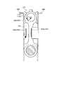
- FIG. 1 is a diagram illustrating the overall configuration of a uniflow scavenging two-cycle engine 100 (crosshead engine).
- the uniflow scavenging two-cycle engine 100 of the present embodiment is used for, for example, ships.
- the uniflow scavenging two-cycle engine 100 includes a cylinder 110, a piston 112, a crosshead 114, a connecting rod 116, a crankshaft 118, an exhaust port 120, an exhaust valve 122, and a scavenging port 124.
- the scavenging reservoir 126, the cooler 128, the scavenging chamber 130, and the combustion chamber 132 are configured.
- the piston 112 has an upper end fixed to the piston rod 112a.
- the lower end (first end) of the piston rod 112 a is connected to a cross head pin 114a in the cross head 114, and the cross head 114 reciprocates together with the piston 112.
- the cross head 114 is restricted from moving in the direction perpendicular to the stroke direction of the piston 112 (left and right direction in FIG. 1) by the cross head shoe 114b.
- the cross head pin 114 a is inserted through a hole provided at the upper end (second end) of the connecting rod 116 and supports the second end of the connecting rod 116.
- the lower end of the connecting rod 116 is connected to the crankshaft 118 so that the crankshaft 118 rotates with respect to the connecting rod 116.
- the first end of the piston rod 112a to which the piston 112 is fixed and the second end of the connecting rod 116 connected to the crankshaft 118 are connected via the cross head 114, and the cross head 114 is connected to the stroke of the piston 112. Move back and forth in the direction.
- the exhaust port 120 is an opening provided in the cylinder head 110 a above the top dead center of the piston 112, and is opened and closed to exhaust the exhaust gas after combustion generated in the cylinder 110.
- the exhaust valve 122 is moved up and down at a predetermined timing by an unillustrated exhaust valve driving device to open and close the exhaust port 120.
- the exhaust gas exhausted through the exhaust port 120 in this way is supplied to the turbine side of the supercharger C through the exhaust pipe 120a and then exhausted to the outside.
- the scavenging port 124 is a hole penetrating from the inner peripheral surface on the lower end side of the cylinder 110 (the inner peripheral surface of the cylinder liner 110 b) to the outer peripheral surface, and a plurality of scavenging ports 124 are provided over the entire periphery of the cylinder 110.
- the scavenging port 124 sucks the active gas into the cylinder 110 according to the sliding motion of the piston 112.
- This active gas contains an oxidizing agent such as oxygen and ozone, or a mixture thereof (for example, air).
- the scavenging reservoir 126 is filled with active gas (for example, air) pressurized by the compressor of the supercharger C, and the active gas is cooled by the cooler 128.
- active gas for example, air
- the cooled active gas is pressed into a scavenging chamber 130 formed in the cylinder jacket 110c.
- the active gas is sucked into the cylinder 110 from the scavenging port 124 due to the differential pressure between the scavenging chamber 130 and the cylinder 110.
- the cylinder head 110a is provided with a liquid fuel injection valve 134.
- a liquid fuel injection valve 134 In the gas operation mode, an appropriate amount of fuel oil is injected from the liquid fuel injection valve 134 at a desired point in the engine cycle.
- the fuel oil is vaporized by the heat of the combustion chamber 132 surrounded by the cylinder head 110a, the cylinder liner 110b, and the piston 112, and is spontaneously ignited and burns in a short time, so that the temperature of the combustion chamber 132 is extremely reduced. Make it high.
- a gas fuel injection valve (not shown) is provided in the vicinity of the scavenging port 124 or in a portion of the cylinder 110 from the scavenging port 124 to the combustion chamber 132, and is injected from the gaseous fuel injection valve and flows into the cylinder 110.
- the fuel gas is reliably burned at a desired timing by being heated by the combustion heat of the fuel oil.
- the piston 112 reciprocates mainly by the expansion pressure due to the combustion of fuel gas.
- the fuel gas is generated, for example, by gasifying LNG (liquefied natural gas).
- LNG liquefied natural gas
- the fuel gas is not limited to LNG, and for example, LPG (liquefied petroleum gas), light oil, heavy oil, etc. can be gasified and applied.
- the uniflow scavenging two-cycle engine 100 selectively executes one of the gas operation mode and the diesel operation mode.
- the uniflow scavenging two-cycle engine 100 is provided with a variable mechanism.
- the variable mechanism will be described in detail.
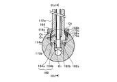
- FIG. 2A and 2B are diagrams for explaining a connecting portion between the piston rod 112a and the cross head pin 114a.
- FIG. 2A shows an enlarged view in which a portion surrounded by an alternate long and short dash line in FIG. 1 is extracted, and
- FIG. 2A shows a cross section taken along line II (b) -II (b) in FIG. 2A.
- the first end of the piston rod 112a is inserted into the crosshead pin 114a.
- the cross head pin 114a is formed with a connection hole 160 extending perpendicularly to the axial direction of the cross head pin 114a (the left-right direction in FIG. 2B).
- the connection hole 160 is a hydraulic chamber, and the first end of the piston rod 112a is inserted into the hydraulic chamber.
- the first end of the piston rod 112a is inserted into the connection hole 160, whereby the cross head pin 114a and the piston rod 112a are connected.
- the piston rod 112a has a large-diameter portion 162a in which the outer diameter of the piston rod 112a is larger than that of the first end side, and is positioned on the first end side of the large-diameter portion 162a.
- a small-diameter portion 162b having a smaller outer diameter is formed.
- the connecting hole 160 is continuous to the connecting rod 116 side with respect to the large-diameter hole 164a located on the piston 112 side in the connecting hole 160 and the large-diameter hole 164a, and has an inner diameter smaller than that of the large-diameter hole 164a. And a small-diameter hole 164b.
- the small diameter portion 162b of the piston rod 112a can be inserted into the small diameter hole portion 164b of the connection hole 160, and the large diameter portion 162a of the piston rod 112a is set to a size that can be inserted into the large diameter hole portion 164a of the connection hole 160.
- the inner peripheral surface of the small-diameter hole portion 164b, the first seal member O 1 constituted by O-ring is described.
- a fixed lid 166 having an outer diameter larger than that of the connection hole 160 is fixed to the upper end (second end) side of the piston rod 112a from the large diameter portion 162a of the piston rod 112a.
- the fixed lid 166 is an annular member, and the piston rod 112a is inserted from above.
- the inner peripheral surface of the fixed cover 166 of the piston rod 112a is inserted, the second sealing member O 2 is arranged constituted by an O-ring.
- a recess 114c that is recessed in the radial direction of the crosshead pin 114a is formed on the outer peripheral surface of the crosshead pin 114a, and a fixed lid 166 is fitted inside the recess 114c.
- a first hydraulic chamber 168a (hydraulic chamber) and a second hydraulic chamber 168b (hydraulic chamber) are formed inside the cross head pin 114a at the connecting portion between the piston rod 112a and the cross head pin 114a.
- the first hydraulic chamber 168a includes a step surface due to a difference in outer diameter between the large diameter portion 162a and the small diameter portion 162b, an inner peripheral surface of the large diameter hole portion 164a, and a step due to a difference in inner diameter between the large diameter hole portion 164a and the small diameter hole portion 164b. Surrounded by a face.
- the second hydraulic chamber 168b is surrounded by the end surface on the upper end side of the piston rod 112a, the inner peripheral surface of the large diameter hole 164a, and the rotation lid 166 in the large diameter portion 162a. That is, the large diameter portion 162a of the piston rod 112a divides the large diameter hole portion 164a into the first end side of the piston rod 112a and the second end side of the connecting rod 116. Then, the first hydraulic chamber 168a is formed by the large-diameter hole 164a defined below the large-diameter portion 162a with the large-diameter portion 162a as a boundary, and the large-diameter portion 164a defined above the large-diameter portion 162a. A second hydraulic chamber 168b is formed by the diameter hole portion 164a.
- a supply oil passage 170a and a drain oil passage 170b communicate with the first hydraulic chamber 168a.
- the supply oil passage 170a has an upper end (second end) that opens to a stepped surface due to an inner diameter difference between the large-diameter hole 164a and the small-diameter hole 164b, and a lower end (first end) that communicates with a later-described hydraulic pressure generator.
- the oil drainage path 170b communicates with a solenoid valve (not shown), and an upper end (second end) opens to a stepped surface due to a difference in inner diameter between the large diameter hole 164a and the small diameter hole 164b.
- An auxiliary oil passage 170c that opens to the wall surface of the fixed lid 166 communicates with the second hydraulic chamber 168b.
- the auxiliary oil passage 170c passes through the inside of the cross head pin 114a via a contact portion between the fixed lid 166 and the cross head pin 114a, and communicates with a hydraulic pump (not shown).
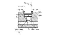
- FIG. 3A and 3B are diagrams for explaining changes in the relative positions of the piston rod 112a and the crosshead pin 114a.
- FIG. 3A shows a state in which the piston rod 112a has entered the connection hole 160 shallowly
- FIG. A state in which the piston rod 112a has entered the connection hole 160 deeply is shown.
- the first hydraulic chamber 168a has a variable length in the stroke direction of the piston 112.
- the inertial force of the piston rod 112a may be large, and the piston rod 112a may move too much to the piston 112 side.
- the hydraulic pressure from the hydraulic pump is applied to the second hydraulic chamber 168b via the auxiliary oil passage 170c to suppress such movement of the piston rod 112a. Yes.
- the uniflow scavenging two-cycle engine 100 is used at a relatively low rotational speed, the inertial force of the piston rod 112a is small, and even if the hydraulic pressure supplied to the second hydraulic chamber 168b is low, the top dead center position can be obtained. Deviation can be suppressed.
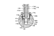
- the piston rod 112a is provided with a flow path hole 172 that extends radially inward from the outer peripheral surface of the piston rod 112a.
- the cross head pin 114a is provided with a through hole 174 that penetrates from the outer peripheral surface side of the cross head pin 114a to the connection hole 160.
- the through hole 174 communicates with the hydraulic pump described above.
- the flow path hole 172 and the through hole 174 are opposed to each other in the radial direction of the piston rod 112a, and the flow path hole 172 and the through hole 174 communicate with each other.
- the end of the flow path hole 172 on the outer peripheral surface side is formed wider than the other part of the flow path hole 172 in the stroke direction of the piston 112 (vertical direction in FIGS. 3A and 3B). As shown in FIGS. 3A and 3B, even if the relative positions of the piston rod 112a and the cross head pin 114a change, the communication state of the flow path hole 172 and the through hole 174 is maintained.
- a third seal member O 3 composed of an O-ring is formed so that the end on the outer peripheral surface side of the flow path hole 172 is sandwiched from above and below along the axial direction of the piston rod 112a. 4 the sealing member O 4 is disposed (see FIG. 2A and B).
- the large-diameter portion 162a has a smaller area facing the inner peripheral surface of the large-diameter hole 164a by the amount corresponding to the flow path hole 172, and is easily inclined with respect to the large-diameter hole 164a.
- the small-diameter portion 162b is guided by the small-diameter hole portion 164b, so that the inclination of the piston rod 112a with respect to the stroke direction is suppressed.
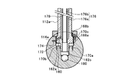
- a cooling oil passage 176 that extends in the stroke direction of the piston 112 and through which cooling oil for cooling the piston 112 and the piston rod 112a flows is formed inside the piston rod 112a.
- a cooling pipe 178 is arranged inside the cooling oil path 176, and the cooling oil path 176 is divided by the cooling pipe 178 into a forward path 176a on the radially outer side of the piston rod 112a and an inner return path 176b.
- the flow path hole 172 opens in the forward path 176 a of the cooling oil path 176.
- the cooling oil supplied from the hydraulic pump flows into the forward path 176 a of the cooling oil path 176 through the through hole 174 and the flow path hole 172.
- the forward path 176a and the return path 176b communicate with each other inside the piston 112, and the cooling oil that has flowed through the forward path 176a returns to the small diameter portion 162b side through the return path 176b when reaching the inner wall of the piston 112.
- the piston 112 is cooled by the cooling oil coming into contact with the inner wall of the cooling oil passage 176 and the inner wall of the piston 112.
- the cross head pin 114 a is formed with an outlet hole 180 extending in the axial direction of the cross head pin 114 a, and the small diameter hole portion 164 b communicates with the outlet hole 180.
- the cooling oil that has flowed into the small-diameter hole 164b from the cooling oil passage 176 is discharged out of the crosshead pin 114 ⁇ a through the outlet hole 180, and circulates to the tank.
- the hydraulic oil supplied to the first hydraulic chamber 168a and the second hydraulic chamber 168b and the cooling oil supplied to the cooling oil passage 176 are both circulated to the same tank and boosted by the same hydraulic pump. For this reason, it is possible to perform the supply of hydraulic oil for applying hydraulic pressure and the supply of cooling oil for cooling with a single hydraulic pump, thereby reducing the cost.
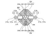
- FIG. 4 is a diagram for explaining the arrangement of the hydraulic pressure generator 200.
- the hydraulic pressure generator 200 includes a main body member 202 and a pair of plunger pressing members 204 a and 204 b.
- the main body member 202 is fixed to one end surface 114d of the cross head pin 114a.
- the main body member 202 reciprocates integrally with the piston 112 and the cross head 114 in the stroke direction of the piston 112.
- the position of the cross head pin 114a in the axial direction is located on the front side in FIG. 4 with respect to the connecting rod 116, and is fixed to the frame 206, respectively.
- the main body member 202 and the plunger pressing members 204a and 204b are arranged so that the axial positions of the cross head pins 114a overlap each other.
- the body member 202 reciprocates together with the piston 112 and the cross head 114, the body member 202 passes between the pair of plunger pressing members 204a and 204b.
- FIGS. 5A and 5B are diagrams illustrating the main body member 202, and a schematic cross-sectional view of the main body member 202 is shown.
- the main body member 202 is formed with a through-hole 208 that penetrates in the left-right direction in FIGS. 5A and 5B, and a pair of plungers 210a and 210b are inserted through the through-hole 208. .
- Each of the plungers 210a and 210b has a plunger main body 212 and a roller 214.
- the plunger body 212 is inserted into the through hole 208 and has a tip protruding from the through hole 208.
- the rollers 214 are provided at the tip of the plunger body 212 protruding from the through hole 208, respectively. 5A and 5B, the roller 214 is rotatable with the direction perpendicular to the paper surface as the rotation axis direction.
- the tips of the plungers 210 a and 210 b are located outside the main body member 202.
- the base ends of the plungers 210 a and 210 b are located inside the through hole 208 of the main body member 202.
- the base end portions 212 a of the plunger main body 212 of the plungers 210 a and 210 b are spaced apart from each other, and the pressure increasing chamber 216 is formed by the base end portion 212 a of the plunger main body 212 and the inner wall of the through hole 208.
- the base end portions 212 a of the plunger main bodies 212 of the plungers 210 a and 210 b face the pressurizing chamber 216 inside the main body member 202.
- the plungers 210 a and 210 b slide in the through hole 208.
- the stroke direction of the piston 112 is the vertical direction
- the plungers 210a and 210b slide in a direction intersecting the stroke direction of the piston 112 (here, a direction perpendicular to the stroke direction of the piston 112). To do.
- the pair of plungers 210a and 210b are provided so as to be spaced apart from each other in the sliding direction across the boosting chamber 216, and in the boosting chamber 216, the pair of plungers 210a and 210b are separated from each other.
- An elastic member 218 for applying a biasing force is provided. Both ends of the elastic member 218 are fixed to base end portions 212a of the plunger main bodies 212 of the plungers 210a and 210b, respectively.
- the introduction port 220 is provided on the upper side of the main body member 202, and the discharge port 222 is provided on the lower side.
- the introduction port 220 is connected to a hydraulic oil supply source, for example, a hydraulic oil tank, and the hydraulic oil is guided from the hydraulic oil tank.
- the discharge port 222 communicates with the first hydraulic chamber 168a via the above-described supply oil passage 170a.
- the main body member 202 is provided with a first communication passage 228 that communicates from the introduction port 220 to the pressure increasing chamber 216.
- the first communication passage 228 is formed with a taper 228a having a smaller inner diameter toward the introduction port 220, and a first check valve 224 is provided closer to the pressure increasing chamber 216 than the taper 228a.
- the first check valve 224 includes a spherical valve body 224a and an elastic spring 224b, and the valve body 224a is biased upward in FIGS. 5A and 5B by the elastic spring 224b.
- the valve body 224a comes into contact with the taper 228a in the first communication passage 228 and causes the first communication passage 228 to enter. close.
- the first check valve 224 suppresses the flow of hydraulic oil from the pressure increasing chamber 216 to the introduction port 220.
- the main body member 202 is provided with a second communication passage 230 that communicates from the pressure increasing chamber 216 to the discharge port 222.
- the second communication passage 230 is formed with a taper 230a whose inner diameter increases toward the discharge port 222, and a second check valve 226 is provided closer to the discharge port 222 than the taper 230a.
- the second check valve 226 includes a spherical valve body 226a and an elastic spring 226b, and the valve body 226a is biased upward in FIGS. 5A and 5B by the elastic spring 226b.
- the valve body 226 a contacts the taper 230 a in the second communication path 230 and closes the second communication path 230. In this way, the second check valve 226 suppresses the flow of hydraulic oil from the discharge port 222 to the pressure increasing chamber 216.
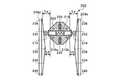
- FIG. 6A to 6C are diagrams for explaining the operation of the hydraulic pressure generator 200.
- FIG. 6A to 6C show a state in which the main body member 202 is moved to the plunger pressing members 204a and 204b side along the stroke direction of the piston 112, compared to the state shown in FIG.
- each of the plunger pressing members 204a and 204b has a first inclined surface 232 (an inclined surface) and a second inclined surface 234 (an inclined surface).
- the first inclined surface 232 is inclined in the direction in which the facing distance between the plunger pressing members 204a and 204b becomes narrower toward the lower side in the stroke direction (lower side in FIG. 6A).
- the 2nd inclined surface 234 inclines in the direction where the opposing space
- the first pressing portion 236 is the upper end portion of the first inclined surface 232 of the plunger pressing members 204a and 204b in FIG. 6A, and the sliding direction of the plungers 210a and 210b (the left-right direction in FIGS. 6A to 6C). ) Is separated from the main body member 202.
- the distance in the left-right direction between the first pressing portion 236 and the main body member 202 is defined as a first distance La.
- the pushing amount of the plungers 210a and 210b toward the boosting chamber 216 is set to a first pushing amount (here, 0).
- the 2nd press part 238 is a site
- the second pressing portion 238 is the second distance Lb in which the horizontal distance from the main body member 202 is smaller than the first distance La, and the facing distance between the plunger pressing members 204a and 204b is the smallest. It is a part.
- the pressing amount of the plungers 210a and 210b toward the boosting chamber 216 becomes a second pressing amount larger than the first pressing amount.
- the roller 214 is pressed by the plunger pressing members 204a and 204b while sliding on the first inclined surface 232, and the plungers 210a and 210b are moved to the first position.
- the pressure is pushed into the pressurizing chamber 216 by the amount pushed by two.
- the plunger pressing members 204a and 204b push the plungers 210a and 210b toward the pressure increasing chamber 216 in the process in which the plungers 210a and 210b move from the first pressing portion 236 to the second pressing portion 238.
- the pressurizing chamber 216 pressurizes the hydraulic oil guided from the introduction port 220 to the main body member 202 and discharges it from the discharge port 222.
- the hydraulic oil discharged from the discharge port 222 flows into the first hydraulic chamber 168a through the supply oil passage 170a, and the relative positions of the piston rod 112a and the cross head pin 114a change.
- the second inclined surface 234 is also the second inclined surface 234 when the main body member 202 moved downward from the second pressing portion 238 moves upward in FIG. 6A in the stroke direction. It operates in the same manner as the one inclined surface 232. That is, in FIG. 6A, the lower end portion of the second inclined surface 234 serves as the first pressing portion 240, and the plunger pressing members 204 a and 204 b have the plungers 210 a and 210 b that are separated from the first pressing portion 240. In the process of moving to the second pressing portion 238, the plungers 210a and 210b are pushed into the pressure increasing chamber 216 side.
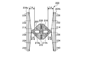
- FIGS. 7A and 7B are diagrams for explaining the control of the hydraulic pressure generator 200.
- a swing mechanism 242 is provided on the plunger pressing member 204a side.
- the swing mechanism 242 includes a support portion 242a and an actuator 242b.
- the support portion 242a pivotally supports the lower end side in FIG. 7A of the plunger pressing member 204a.
- the plunger pressing member 204a can swing to the position shown in FIG. 7B with the fulcrum pivotally supported by the support portion 242a as the rotation axis center. Further, the support portion 242a biases the plunger pressing member 204a in the direction of rotating counterclockwise.
- the actuator 242b is, for example, a hydraulic type, and a roller 242c is provided at the tip. Then, the actuator 242b receives a pressing force by hydraulic pressure, and the tip portion moves in the left-right direction in FIG. 7A. The roller 242c comes into contact with the plunger pressing member 204a from the left side in FIG. 7A and presses the plunger pressing member 204a in the clockwise rotation direction.
- the plunger pressing members 204a and 204b are in the pressure increasing position where the pressure of the hydraulic oil in the pressure increasing chamber 216 can be increased.
- the actuator 242b is activated and the roller 242c moves to the left as shown in FIG. 7B
- the plunger pressing member 204a swings following the roller 242c by the urging force from the support portion 242a, and the plunger pressing member
- the separation distance between the second pressing portion 238 of 204a and the second pressing portion 238 of the plunger pressing member 204b is increased.
- the plunger pressing member 204a reduces the volume of the boosting chamber 216 shown in FIG. 7A, and boosts the hydraulic oil in the boosting chamber 216 shown in FIG. 7B from the boosting position where the hydraulic fluid can be boosted. Move to the retreat position where it becomes impossible. Therefore, the hydraulic pressure generator 200 can switch ON / OFF of hydraulic pressure generation with a simple configuration. When the hydraulic pressure is unnecessary, by setting the plunger pressing member 204a to the retracted position, it is possible to suppress fuel consumption without applying unnecessary resistance to the piston 112.
- produce can be adjusted by controlling the plunger press member 204a to the arbitrary positions from the pressure
- the hydraulic pressure can be generated by the hydraulic pressure generator 200, it is not necessary to install a new hydraulic pump for generating the hydraulic pressure in the crosshead engine. Alternatively, even if a hydraulic pump is installed, the installed hydraulic pump has a small output, and the hydraulic pressure generator 200 can boost the hydraulic oil to a high pressure by the power of the piston 112.
- the roller 214 contacts the plunger pressing members 204a and 204b from the direction intersecting the stroke direction of the piston 112. To do. Therefore, the impact at the time of contact is small, and it is possible to suppress the shock wave generated in the hydraulic oil. Further, the plunger pressing members 204a and 204b can be arranged at any position in the movement range along the stroke direction of the main body member 202, and the degree of freedom of installation is high.
- the hydraulic pressure generating device 200 generates the hydraulic pressure for changing the relative positions of the piston rod 112a and the cross head pin 114a has been described.
- the hydraulic pressure generated by the hydraulic pressure generating device 200 is not limited to this. You may use for the use.
- the main body member 202 is provided on the cross head 114 .
- the main body member 202 moves integrally with the piston 112 in the stroke direction of the piston 112
- the main body member is attached to a member other than the cross head 114. 202 may be provided.
- the main body member 202 is provided on the cross head 114, it can be easily arranged without interfering with other members.
- both the 1st inclined surface 232 and the 2nd inclined surface 234 are essential. Absent. However, by providing the first inclined surface 232 and the second inclined surface 234, the hydraulic pressure can be gradually increased. In addition, only one of the first inclined surface 232 and the second inclined surface 234 may be provided, but by providing both the first inclined surface 232 and the second inclined surface 234, 2 may be provided during one stroke. The hydraulic pressure can be increased, allowing for quick pressure increase.
- first inclined surface 232 and the second inclined surface 234 are illustrated as linear shapes, the first inclined surface 232 and the second inclined surface 234 are curved surfaces calculated so that the hydraulic pressure increase rate due to movement of the main body member 202 in the stroke direction does not change abruptly. There may be.
- the plunger pressing members 204a and 204b are operated from the boosting position to the retracted position.
- the plunger pressing members 204a and 204b are not operated, for example, the operation discharged from the discharge port 222.
- a switching valve or the like may be provided in the oil passage of oil to switch ON / OFF of pressure increase.
- the plungers 210a and 210b have been described as being provided with a pair of the pressure increasing chamber 216 spaced apart from each other in the sliding direction. However, only one of the plungers 210a and 210b is provided. Also good. However, when both the plungers 210a and 210b are provided, the elastic member 218 is provided in the pressure increasing chamber 216, and the plunger pressing members 204a and 204b are provided for the pair of plungers 210a and 210b, the following effects are obtained.
- the desired pressure increase performance is exhibited as long as the distance between the plunger pressing members 204a and 204b is not shifted. can do. That is, by providing a pair of plungers 210a and 210b, strict management of dimensions is not required, and design work and assembly work can be simplified.
- first check valve 224 and the second check valve 226 are provided in the main body member 202 .
- first check valve 224 and the second check valve 226 are provided.
- an electromagnetic valve or the like may be provided.
- the flow of the hydraulic oil is controlled with a simple configuration and high accuracy, and the hydraulic pressure in the boost chamber 216 is increased. It becomes possible to do.
- the present disclosure can be used for a crosshead type engine hydraulic pressure generator in which a crosshead is fixed to a piston rod, and a crosshead type engine.
Landscapes
- Engineering & Computer Science (AREA)
- General Engineering & Computer Science (AREA)
- Mechanical Engineering (AREA)
- Chemical & Material Sciences (AREA)
- Combustion & Propulsion (AREA)
- Reciprocating Pumps (AREA)
- Output Control And Ontrol Of Special Type Engine (AREA)
- Lubrication Of Internal Combustion Engines (AREA)
- Details Of Reciprocating Pumps (AREA)
Abstract
クロスヘッド型エンジンの油圧発生装置(200)は、先端が本体部材の外方に位置し、基端が本体部材(202)の内部で昇圧室(216)に面し、ピストンのストローク方向に交差する方向に摺動するプランジャ(210a、210b)と、プランジャの摺動方向に本体部材から離隔して配され、本体部材との離隔距離が第1の距離(La)であって、昇圧室側へのプランジャの押し込み量が第1押し込み量となる第1押圧部(236、240)と、本体部材との離隔距離が第2の距離(Lb)であって、昇圧室側へのプランジャの押し込み量が第1押し込み量よりも大きい第2押し込み量となる第2押圧部(238)と、を有し、プランジャが第1押圧部から第2押圧部へ移動する過程で、プランジャを昇圧室側へ押し込むプランジャ押圧部材(204a、204b)と、を備える。
Description
本開示は、ピストンロッドにクロスヘッドが固定されたクロスヘッド型エンジンの油圧発生装置、および、クロスヘッド型エンジンに関する。
本願は、2015年5月11日に日本に出願された特願2015-96717号に基づき優先権を主張し、その内容をここに援用する。
本願は、2015年5月11日に日本に出願された特願2015-96717号に基づき優先権を主張し、その内容をここに援用する。
舶用エンジンに多く採用されているクロスヘッド型エンジンでは、ピストンが固定されるピストンロッドの端部にクロスヘッドが設けられている。連接棒(コネクティングロッド)は、クロスヘッドとクランクシャフトを連結しており、クロスヘッドの往復運動がクランクシャフトの回転運動に変換される。
特許文献1のエンジンは、このようなクロスヘッド型エンジンであって、クロスヘッド内に油圧ピストンが配され、油圧ピストンが油圧によって作動することで、ピストンの上死点の位置を変化させて圧縮比を可変としている。
上述した特許文献1に記載のようなクロスヘッド型エンジンに油圧機構を設ける場合、油圧を昇圧するための油圧ポンプを設ける必要がある。また、油圧機構の用途によっては、高圧を生じさせることが可能な、出力の大きな油圧ポンプが必要となる場合がある。
本開示は、このような課題に鑑み、新たな油圧ポンプの設置が不要、または、新たに設置する油圧ポンプを小出力とすることが可能なクロスヘッド型エンジンの油圧発生装置、および、クロスヘッド型エンジンを提供することを目的としている。
上記課題を解決するために、本開示の第一の態様に係るクロスヘッド型エンジンの油圧発生装置は、ピストンが固定されるピストンロッドの第1端、および、クランクシャフトに連結される連接棒の第2端がクロスヘッドを介して接続され、クロスヘッドがピストンのストローク方向に往復移動するクロスヘッド型エンジンの油圧発生装置であって、ピストンのストローク方向に、ピストンおよびクロスヘッドと一体に往復移動する本体部材と、本体部材に形成され、作動油の供給源に接続される導入ポート、および、作動油の供給先に接続される吐出ポートに連通し、導入ポートから本体部材に導かれた作動油を昇圧して吐出ポートから吐出する昇圧室と、先端が本体部材の外方に位置し、基端が本体部材の内部で昇圧室に面し、ピストンのストローク方向に交差する方向に摺動するプランジャと、プランジャの摺動方向に本体部材から離隔して配され、本体部材との離隔距離が第1の距離であって、昇圧室側へのプランジャの押し込み量が第1押し込み量となる第1押圧部と、第1押圧部とストローク方向の位置を異にし、本体部材との離隔距離が第1の距離よりも小さい第2の距離であって、昇圧室側へのプランジャの押し込み量が第1押し込み量よりも大きい第2押し込み量となる第2押圧部と、を有し、プランジャが第1押圧部から第2押圧部へ移動する過程で、プランジャを昇圧室側へ押し込むプランジャ押圧部材と、を備える。
また、上記課題を解決するために、本開示のクロスヘッド型エンジンは、上記の油圧発生装置を備える。
本開示によれば、クロスヘッド型エンジンに、油圧発生のための新たな油圧ポンプの設置が不要、または、新たに設置する油圧ポンプを小出力とすることが可能となる。
以下に添付図面を参照しながら、本開示の好適な実施形態について詳細に説明する。本実施形態に示す寸法、材料、その他具体的な数値等は、開示の理解を容易とするための例示にすぎず、特に断る場合を除き、本開示を限定するものではない。なお、本明細書および図面において、実質的に同一の機能、構成を有する要素については、同一の符号を付することにより重複説明を省略し、また本開示に直接関係のない要素は図示を省略する。
以下の実施形態では、気体燃料である燃料ガスを主に燃焼させるガス運転モードと、液体燃料である燃料油を燃焼させるディーゼル運転モードのいずれかの運転モードを選択的に実行することができる、所謂デュアルフューエル型のエンジンについて説明する。また、2行程で1サイクルを完結するエンジン(2サイクルエンジン、2ストロークエンジン)であって、シリンダ内部をガスが一方向に流れるユニフロー掃気式である場合について説明する。しかし、エンジンの種類は、デュアルフューエル型、2サイクル型、ユニフロー掃気式に限られず、クロスヘッド型のエンジンであればよい。
図1は、ユニフロー掃気式2サイクルンジン100(クロスヘッド型エンジン)の全体構成を説明する図である。本実施形態のユニフロー掃気式2サイクルエンジン100は、例えば、船舶等に用いられる。具体的に、ユニフロー掃気式2サイクルンジン100は、シリンダ110と、ピストン112と、クロスヘッド114と、連接棒116と、クランクシャフト118と、排気ポート120と、排気弁122と、掃気ポート124と、掃気溜126と、冷却器128と、掃気室130と、燃焼室132とを含んで構成される。
ユニフロー掃気式2サイクルンジン100では、ピストン112の上昇行程および下降行程の2行程の間に、排気、吸気、圧縮、燃焼、膨張が行われて、ピストン112がシリンダ110内を往復移動する。ピストン112には、ピストンロッド112aの上端が固定されている。また、ピストンロッド112 aの下端(第1端)には、クロスヘッド114におけるクロスヘッドピン114aが連結されており、クロスヘッド114は、ピストン112とともに往復移動する。クロスヘッド114はクロスヘッドシュー114bによって、ピストン112のストローク方向に垂直な方向(図1中、左右方向)の移動が規制されている。
クロスヘッドピン114aは、連接棒116の上端(第2端)に設けられた孔に挿通されており、連接棒116の第2端を支持している。また、連接棒116の下端は、クランクシャフト118に連結され、連接棒116に対してクランクシャフト118が回転する構造となっている。その結果、ピストン112の往復移動に伴いクロスヘッド114が往復移動すると、その往復移動に連動して、クランクシャフト118が回転する。
すなわち、ピストン112が固定されるピストンロッド112aの第1端、および、クランクシャフト118に連結される連接棒116の第2端がクロスヘッド114を介して接続され、クロスヘッド114がピストン112のストローク方向に往復移動する。
排気ポート120は、ピストン112の上死点より上方のシリンダヘッド110aに設けられた開口部であり、シリンダ110内で生じた燃焼後の排ガスを排気するために開閉される。排気弁122は、不図示の排気弁駆動装置によって所定のタイミングで上下に移動され、排気ポート120を開閉する。このようにして排気ポート120を介して排気された排ガスは、排気管120aを介して過給機Cのタービン側に供給された後、外部に排気される。
掃気ポート124は、シリンダ110の下端側の内周面(シリンダライナ110bの内周面)から外周面まで貫通する孔であり、シリンダ110の全周囲に亘って、複数設けられている。そして、掃気ポート124は、ピストン112の摺動動作に応じてシリンダ110内に活性ガスを吸入する。この活性ガスは、酸素、オゾン等の酸化剤、または、その混合気(例えば空気)を含む。
掃気溜126には、過給機Cのコンプレッサによって加圧された活性ガス(例えば空気)が封入されており、冷却器128によって活性ガスが冷却されている。冷却された活性ガスはシリンダジャケット110c内に形成された掃気室130に圧入される。そして、掃気室130とシリンダ110内の差圧により、掃気ポート124からシリンダ110内に活性ガスが吸入される。
また、シリンダヘッド110aには、液体燃料噴射弁134が設けられる。ガス運転モードにおいては、エンジンサイクルにおける所望の時点で適量の燃料油が液体燃料噴射弁134から噴射される。この燃料油は、シリンダヘッド110aと、シリンダライナ110bと、ピストン112とに囲まれた燃焼室132の熱で気化するとともに自然着火し、僅かな時間で燃焼して、燃焼室132の温度を極めて高くする。掃気ポート124近傍、または、シリンダ110のうち、掃気ポート124から燃焼室132までの部位に不図示の気体燃料噴射弁が設けられており、気体燃料噴射弁から噴射されてシリンダ110内に流入した燃料ガスは、燃料油の燃焼熱によって昇温されることで、所望のタイミングで確実に燃焼する。ピストン112は、主に燃料ガスの燃焼による膨張圧によって往復移動する。
ここで、燃料ガスは、例えば、LNG(液化天然ガス)をガス化して生成される。また、燃料ガスには、LNGに限らず、例えば、LPG(液化石油ガス)、軽油、重油等をガス化して適用することもできる。
一方、ディーゼル運転モードにおいては、気体燃料噴射弁からの燃料ガスの噴射が停止されるとともに、ガス運転モードにおける燃料油の噴射量よりも多量の燃料油がパイロット噴射弁から噴射される。ピストン112は、燃料ガスではなく、燃料油の燃焼による膨張圧によって往復移動する。
このように、ユニフロー掃気式2サイクルエンジン100は、ガス運転モードとディーゼル運転モードのいずれかの運転モードを選択的に実行する。そして、それぞれの選択モードに応じてピストン112の圧縮比を可変とするため、ユニフロー掃気式2サイクルエンジン100には、可変機構が設けられている。以下、可変機構について詳述する。
図2AおよびBは、ピストンロッド112aとクロスヘッドピン114aとの連結部分を説明する図であり、図2Aには、図1の一点鎖線で囲まれた部分を抽出した拡大図を示し、図2B には、図2A のII(b)-II(b)線に沿った断面を示す。
図2AおよびBに示すように、クロスヘッドピン114aには、ピストンロッド112aの第1端が挿入される。具体的に、クロスヘッドピン114aには、クロスヘッドピン114aの軸方向(図2B中、左右方向)に垂直に延びる連結穴160が形成されている。この連結穴160は油圧室となっており、この油圧室に、ピストンロッド112aの第1端が挿入されている。このように、連結穴160にピストンロッド112aの第1端が挿入されることで、クロスヘッドピン114aと、ピストンロッド112aが連結される。
より詳細に説明すると、ピストンロッド112aには、ピストンロッド112aの外径が第1端側よりも大きい大径部162aと、大径部162aよりも第1端側に位置し、大径部162aよりも外径が小さい小径部162bが形成されている。
そして、連結穴160は、連結穴160におけるピストン112側に位置する大径穴部164aと、大径穴部164aに対して連接棒116側に連続し、大径穴部164aよりも内径が小さい小径穴部164bとを有している。
ピストンロッド112aの小径部162bは、連結穴160の小径穴部164bに挿入可能であって、ピストンロッド112aの大径部162aは、連結穴160の大径穴部164aに挿入可能なサイズに設定されている。小径穴部164bの内周面には、Oリングで構成される第1シール部材O1 が記される。
ピストンロッド112aの大径部162aよりピストンロッド112aの上端(第2端)側には、連結穴160よりも外径が大きい固定蓋166が固定されている。固定蓋166は環状部材であって、ピストンロッド112aが上方から挿通されている。ピストンロッド112aが挿通される固定蓋166の内周面には、Oリングで構成される第2シール部材O2が配される。
クロスヘッドピン114aの外周面には、クロスヘッドピン114aの径方向に窪んだ窪み114cが形成されており、この窪み114cの内部に固定蓋166が嵌合する。
また、ピストンロッド112aとクロスヘッドピン114aとの連結部分における、クロスヘッドピン114aの内部には、第1油圧室168a(油圧室)および第2油圧室168b(油圧室)が形成されている。
第1油圧室168aは、大径部162aと小径部162bの外径差による段差面と、大径穴部164aの内周面と、大径穴部164aと小径穴部164bの内径差による段差面によって囲まれる。
第2油圧室168bは、大径部162aのうち、ピストンロッド112aの上端側の端面と、大径穴部164aの内周面と、回定蓋166によって囲まれる。つまり、ピストンロッド112aの大径部162aによって、大径穴部164aが、ピストンロッド112aの第1端側と、連接棒116の第2端側とに区画される。そして、大径部162aを境にして、大径部162aよりも下側に区画された大径穴部164aによって第1油圧室168aが形成され、大径部162aよりも上側に区画された大径穴部164aによって第2油圧室168bが形成されている。
第1油圧室168aには、供給油路170aおよび排油路170bが連通している。供給油路170aは、上端(第2端)が大径穴部164aと小径穴部164bの内径差による段差面に開口し、下端(第1端)が後述する油圧発生装置に連通している。排油路170bは、不図示の電磁弁に連通し、かつ上端(第2端)が大径穴部164aと小径穴部164bの内径差による段差面に開口している。
第2油圧室168bには、固定蓋166の壁面に開口する補助油路170cが連通している。補助油路170cは、固定蓋166とクロスヘッドピン114aとの当接部分を介してクロスヘッドピン114aの内部を通り、不図示の油圧ポンプに連通している。
図3AおよびBは、ピストンロッド112aとクロスヘッドピン114aの相対的な位置の変化を説明する図であり、図3Aは、ピストンロッド112aが連結穴160に浅く進入した状態を示し、図3Bは、ピストンロッド112aが連結穴160に深く進入した状態を示す。
第1油圧室168aは、ピストン112のストローク方向の長さが可変となっており、第1油圧室168aに作動油を供給した状態で第1油圧室168aを密閉すると、図3Aの状態を維持可能となっている。
そして、不図示の電磁弁が開口すると、ピストン112の往復移動によるピストンロッド112aおよびクロスヘッドピン114aからの圧縮荷重によって、作動油が第1油圧室168aから排油路170bを通って電磁弁側に排出される。その結果、図3Bに示すように、ピストン112のストローク方向に沿った第1油圧室168aの長さが短くなる。一方、第2油圧室168bでは、ピストン112のストローク方向に沿った長さが長くなる。
第1油圧室168aおよび第2油圧室168bのピストン112のストローク方向に沿った長さが変更された分、ピストンロッド112aがクロスヘッドピン114aの連結穴160(油圧室)に進入する進入位置(進入深さ)が変化する。このように、ピストンロッド112aとクロスヘッドピン114aの相対的な位置を変化させることで、ピストン112の上死点および下死点の位置が可変となる。
ところで、図3Bに示す状態でピストン112が上死点に到達したとき、クロスヘッドピン114aは連接棒116によってピストン112のストローク方向の位置が固定されている。一方、ピストンロッド112aは、クロスヘッドピン114aに連結されているものの、第2油圧室168bの分だけ、ピストン112のストローク方向に遊びが生じている。
そのため、ユニフロー掃気式2サイクルエンジン100の回転数によってはピストンロッド112aの慣性力が大きく、ピストンロッド112aがピストン112側に移動しすぎてしまう可能性がある。このように上死点位置のずれが生じないように、第2油圧室168bには、補助油路170cを介して油圧ポンプからの油圧を作用させ、このようなピストンロッド112aの移動を抑えている。
また、ユニフロー掃気式2サイクルエンジン100は、比較的低速の回転数で用いられるため、ピストンロッド112aの慣性力が小さく、第2油圧室168bに供給する油圧が低くても、上死点位置のずれを抑えることができる。
また、ピストンロッド112aには、ピストンロッド112aの外周面から径方向内側に向かう流路穴172が設けられている。また、クロスヘッドピン114aには、クロスヘッドピン114aの外周面側から連結穴160まで貫通する貫通孔174が設けられている。貫通孔174は、上述の油圧ポンプと連通している。
また、流路穴172と貫通孔174は、ピストンロッド112aの径方向に対向しており、流路穴172と貫通孔174が連通している。流路穴172の外周面側の端部は、流路穴172の他の部位よりも、ピストン112のストローク方向(図3AおよびB中、上下方向)の流路幅が広く形成されており、図3AおよびBに示すように、ピストンロッド112aとクロスヘッドピン114aの相対的な位置が変っても、流路穴172と貫通孔174の連通状態が維持される。
ピストンロッド112aの外周面には、流路穴172の外周面側の端部をピストンロッド112aの軸方向に沿って上下から挟むように、Oリングで構成される第3シール部材O3、第4シール部材O4が配される(図2AおよびB参照)。
大径部162aは、流路穴172の分だけ、大径穴部164aの内周面に対向する面積が小さくなり、大径穴部164aに対して傾き易くなる。これに対し、小径部162bが小径穴部164bにガイドされることで、ピストンロッド112aの上記ストローク方向に対する傾きが抑えられている。
そして、ピストンロッド112aの内部には、ピストン112のストローク方向に延び、ピストン112およびピストンロッド112aを冷却する冷却油が流通する冷却油路176が形成されている。冷却油路176の内部には冷却管178が配されており、冷却油路176は、冷却管178によってピストンロッド112aの径方向外側の往路176aと内側の復路176bに分けられている。流路穴172は、冷却油路176のうちの往路176aに開口している。
油圧ポンプから供給された冷却油は、貫通孔174、流路穴172を介して冷却油路176の往路176aに流入する。往路176aと復路176bは、ピストン112の内部で連通しており、往路176aを流れた冷却油は、ピストン112の内壁に到達すると復路176bを通って、小径部162b側に戻る。冷却油路176の内壁およびピストン112の内壁に冷却油が接触することで、ピストン112が冷却される。
また、クロスヘッドピン114aには、クロスヘッドピン114aの軸方向に延びる出口孔180が形成されており、小径穴部164bは、出口孔180に連通している。ピストン112を冷却した後に、冷却油路176から小径穴部164bに流入した冷却油は、出口孔180を通って、クロスヘッドピン114 a外に排出され、タンクに環流する。
第1油圧室168aおよび第2油圧室168bに供給される作動油と、冷却油路176に供給される冷却油は、いずれも同じタンクに環流して同じ油圧ポンプで昇圧される。そのため、油圧を作用させる作動油の供給と、冷却用の冷却油の供給を、1つの油圧ポンプで遂行でき、コストを低減することが可能となる。
続いて、供給油路170aの下端(第1端)に連通し、供給油路170aを介して第1油圧室168aに作動油を圧入する油圧発生装置について詳述する。
図4は、油圧発生装置200の配置を説明する図である。図4に示すように、油圧発生装置200は、本体部材202と一対のプランジャ押圧部材204a、204bとを有している。本体部材202は、クロスヘッドピン114aの一方の端面114dに固定されている。そして、本体部材202は、ピストン112のストローク方向に、ピストン112およびクロスヘッド114と一体に往復移動する。
プランジャ押圧部材204a、204bは、それぞれ、クロスヘッドピン114aの軸方向の位置が、連接棒116よりも、図4中、手前側に位置しており、それぞれ、架構206に固定されている。また、本体部材202とプランジャ押圧部材204a、204bとは、クロスヘッドピン114aの軸方向の位置が重なり合うように配置されている。そして、本体部材202は、ピストン112およびクロスヘッド114と共に往復移動するとき、一対のプランジャ押圧部材204a、204bの間を通過する。
図5AおよびBは、本体部材202を説明する図であり、本体部材202の概略断面図を示す。図5AおよびBに示すように、本体部材202には、図5AおよびB中、左右方向に貫通する貫通孔208が形成されており、貫通孔208に一対のプランジャ210a、210bが挿通されている。
プランジャ210a、210bは、それぞれ、プランジャ本体212と、ローラ214とを有する。プランジャ本体212は、貫通孔208に挿通されるとともに先端部が貫通孔208から突出しており、ローラ214は、プランジャ本体212のうちの貫通孔208から突出した先端部にそれぞれ設けられる。ローラ214は、図5AおよびB中、紙面に垂直な方向を回転軸方向として回転自在となっている。
すなわち、プランジャ210a、210bの先端(ローラ214のうちプランジャ本体212と反対側の端部214a) は、本体部材202の外方に位置する。また、プランジャ210a、210bの基端(プランジャ本体212のうちローラ214と反対側の端部212a) は、本体部材202の貫通孔208の内部に位置している。
また、プランジャ210a、210bのプランジャ本体212の基端部212aは互いに離隔しており、これらプランジャ本体212の基端部212aおよび、貫通孔208の内壁によって昇圧室216が形成されている。
すなわち、プランジャ210a、210bのプランジャ本体212の基端部212a(プランジャ210a、210bの基端)は、本体部材202の内部で昇圧室216に面している。そして、プランジャ210a、210bは、貫通孔208内を摺動する。図5AおよびB中、ピストン112のストローク方向は、上下方向であって、プランジャ210a、210bは、ピストン112のストローク方向に交差する方向(ここでは、ピストン112のストローク方向に対する垂直方向)に摺動する。
このように、昇圧室216を挟んで摺動方向に互いに離隔して1対のプランジャ210a、210bが設けられており、昇圧室216には、1対のプランジャ210a 、210bを互いに離隔する方向に付勢力を作用させる弾性部材218が設けられる。弾性部材218の両端は、プランジャ210a、210bのプランジャ本体212の基端部212aにそれぞれ固定されている。
本体部材202のうち、図5AおよびB中、上側には導入ポート220が設けられ、下側には吐出ポート222が設けられている。導入ポート220は、作動油の供給源、例えば作動油タンクに接続されており、作動油タンクから作動油が導かれる。吐出ポート222は、上述した供給油路170aを介して第1油圧室168aに連通している。
また、本体部材202には、導入ポート220から昇圧室216まで連通する第1連通路228が設けられている。第1連通路228は、導入ポート220側ほど内径が小さくなるテーパ228aが形成され、テーパ228aよりも昇圧室216側には、第1逆止弁224が設けられている。具体的に、第1逆止弁224は、球状の弁体224aと弾性バネ224bを有し、弁体224aが弾性バネ224bによって図5AおよびB中、上側に付勢されている。導入ポート220から昇圧室216側に作動油が流れるとき、図5Aに示すように、弁体224aは作動油の流れに押されて第1連通路228を開き、導入ポート220から昇圧室216への作動油の流れを許容する。
一方、昇圧室216の油圧が高まり、昇圧室216から導入ポート220側に作動油が流れようとしても、弁体224aが第1連通路228内のテーパ228aに当接して第1連通路228を閉じる。こうして、第1逆止弁224は、昇圧室216から導入ポート220への作動油の流れを抑止する。
また、本体部材202には、昇圧室216から吐出ポート222まで連通する第2連通路230が設けられている。第2連通路230は、吐出ポート222側ほど内径が大きくなるテーパ230aが形成され、テーパ230aよりも吐出ポート222側には、第2逆止弁226が設けられている。具体的に、第2逆止弁226は、球状の弁体226aと弾性バネ226bを有し、弁体226aが弾性バネ226bによって図5AおよびB中、上側に付勢されている。昇圧室216の油圧が高まり、昇圧室216から吐出ポート222側に作動油が流れるとき、図5Bに示すように、弁体226aは作動油の流れに押されて第2連通路230を開き、昇圧室216から吐出ポート222への作動油の流れを許容する。
一方、吐出ポート222から昇圧室216側に作動油が流れようとしても、弁体226aが第2連通路230内のテーパ230aに当接して第2連通路230を閉じる。こうして、第2逆止弁226は、吐出ポート222から昇圧室216への作動油の流れを抑止する。
図6A~Cは、油圧発生装置200の作用を説明する図である。図6A~Cでは、図4に示す状態よりも、本体部材202がプランジャ押圧部材204a、204b側に、ピストン112のストローク方向に沿って移動した状態を示す。
図6Aに示すように、プランジャ押圧部材204a、204bは、それぞれ、第1傾斜面232(傾斜面)と第2傾斜面234(傾斜面)を有する。第1傾斜面232は、上記ストローク方向の下側(図6A中、下側)ほど、プランジャ押圧部材204a、204bの対向間隔が狭くなる方向に傾斜する。また、第2傾斜面234は、上記ストローク方向の下側ほど、プランジャ押圧部材204a、204bの対向間隔が広くなる方向に傾斜する。
第1押圧部236は、プランジャ押圧部材204a,204bの第1傾斜面232のうち、図6A中、上側の端部であり、プランジャ210a、210bの摺動方向(図6A~C中、左右方向)に本体部材202から離隔して配されている。第1押圧部236と本体部材202との上記左右方向の離隔距離を、第1の距離Laとする。そして、昇圧室216側へのプランジャ210a、210bの押し込み量を第1押し込み量(ここでは、0)とする。
すなわち、本体部材202が上記ストローク方向に図6A~C中、下側に向かつて移動し、図6Aに示すように、ローラ214が第1押圧部236に対向したとき、ローラ214は、第1押圧部236から離隔しており、プランジャ210a、210bは、第1押圧部236により押し込まれない。そして、本体部材202が図6Bの位置まで移動すると、ローラ214がプランジャ押圧部材204a、204bに当接する。
第2押圧部238は、第1押圧部236と上記ストローク方向の位置を異にする部位であって、プランジャ押圧部材204a、204bの第1傾斜面232のうち、図6A中、下側の端部である。すなわち、第2押圧部238は、本体部材202との上記左右方向の離隔距離が第1の距離Laよりも小さい第2の距離Lbであり、プランジャ押圧部材204a、204bの対向間隔が最も小さくなる部位である。この第2押圧部238では、昇圧室216側へのプランジャ210a、210bの押し込み量が第1押し込み量よりも大きい第2押し込み量となる。
すなわち、本体部材202が図6Bの位置から図6Cの位置まで移動する間に、ローラ214が第1傾斜面232を摺動しながらプランジャ押圧部材204a,204bに押圧され、プランジャ210a、210bが第2押し込み量分、昇圧室216側に押し込まれる。
このように、プランジャ押圧部材204a、204bは、プランジャ210a、210bが第1押圧部236から第2押圧部238へ移動する過程で、プランジャ210a、210bを昇圧室216側へ押し込む。
その結果、昇圧室216は、導入ポート220から本体部材202に導かれた作動油を昇圧して吐出ポート222から吐出する。吐出ポート222から吐出された作動油は、供給油路170aを介して第1油圧室168aに流入し、ピストロッド112aとクロスヘッドピン114aの相対的な位置が変化する。
ここでは、本体部材202が上記ストローク方向に、図6A中、下側に向かって移動する場合について説明した。重複説明を避けるため詳細は割愛するが、第2押圧部238より下方に移動した本体部材202が上記ストローク方向に、図6A中、上側に向かって移動する場合も、第2傾斜面234が第1傾斜面232と同様に作用する。すなわち、第2傾斜面234のうち、図6A中、下側の端部が第1押圧部240となっており、プランジャ押圧部材204a、204bは、プランジャ210a、210bが第1押圧部240から第2押圧部238へ移動する過程で、プランジャ210a、210bを昇圧室216側へ押し込む。
図7AおよびBは、油圧発生装置200の制御を説明する図である。図7AおよびBに示すように、プランジャ押圧部材204a側には、揺動機構242が設けられている。揺動機構242は、支持部242aと、アクチュエータ242bで構成される。
支持部242aは、プランジャ押圧部材204aのうち、図7A中、下端側を軸支する。プランジャ押圧部材204aは、支持部242aで軸支された支点を回転軸中心として、図7Bに示す位置まで揺動可能となっている。また、支持部242aは、プランジャ押圧部材204aを、反時計回りに回転する方向に付勢している。
アクチュエータ242bは、例えば、油圧式であって、先端部にローラ242cが設けられている。そして、アクチュエータ242bは、油圧による押圧力を受けて、先端部が、図7A中、左右方向に移動する。ローラ242cは、プランジャ押圧部材204aに図7A中、左側から当接して、プランジャ押圧部材204aを時計回りに回転する方向に押圧する。
図7Aに示す配置では、プランジャ押圧部材204a、204bは、昇圧室216における作動油の昇圧が可能となる昇圧位置となっている。そして、アクチュエータ242bが作動し、図7Bに示すように、ローラ242cが左側に移動すると、プランジャ押圧部材204aが支持部242aからの付勢力によって、ローラ242cに追従して揺動し、プランジャ押圧部材204aの第2押圧部238と、プランジャ押圧部材204bの第2押圧部238の離隔距離が大きくなる。
その結果、プランジャ210a、210bが第2押圧部238に対向する位置まで本体部材202が移動したとき、プランジャ210bは第2押圧部238に押圧されて、図7B中、左側に移動するものの、その分、プランジャ210aが左側に移動することから、昇圧室216の容積は変わらず、作動油は昇圧されない。その後、プランジャ押圧部材204aが再び揺動するまで、昇圧室216における作動油の昇圧が不可能となる。
このように、プランジャ押圧部材204aは、図7Aに示す、昇圧室216の容積を縮小させ、作動油の昇圧が可能となる昇圧位置から、図7Bに示す、昇圧室216における作動油の昇圧が不可能となる退避位置まで移動する。そのため、油圧発生装置200では、簡易な構成で、油圧の発生のON、OFFを切換可能となっている。油圧が不要の場合、プランジャ押圧部材204aを退避位置とすることで、ピストン112に不要な抵抗を作用させずに燃料の消費を抑制できる。
また、プランジャ押圧部材204aを、図7Aに示す昇圧位置から図7Bに示す退避位置までの任意の位置に制御することで、発生させる油圧の大きさを調整可能となる。
上述したように、油圧発生装置200によって油圧を発生させることができるため、クロスヘッド型エンジンにおける、油圧発生のための新たな油圧ポンプの設置が不要となる。または、油圧ポンプを設置するとしても、設置する油圧ポンプを小出力とし、油圧発生装置200が、ピストン112の動力で、作動油を高圧まで昇圧可能となる。
また、油圧発生装置200では、プランジャ210a、210bがプランジャ押圧部材204a、204bに押圧され始めるとき、ローラ214は、プランジャ押圧部材204a、204bに対して、ピストン112のストローク方向に交差する方向から接触する。そのため、接触時の衝撃が小さく、作動油に生じる衝撃波を抑制することが可能となる。また、プランジャ押圧部材204a、204bは、本体部材202の上記ストローク方向に沿った移動範囲の任意の位置に配置でき、設置の自由度が高い。
上述した実施形態では、油圧発生装置200がピストンロッド112aとクロスヘッドピン114aの相対的な位置を可変とするための油圧を発生させる場合について説明したが、油圧発生装置200が発生させた油圧を他の用途に用いてもよい。
また、上述した実施形態では、本体部材202がクロスヘッド114に設けられている場合について説明したが、ピストン112のストローク方向にピストン112と一体に移動すれば、クロスヘッド114以外の部材に本体部材202を設けてもよい。ただし、本体部材202をクロスヘッド114に設ける場合、他の部材と干渉せずに容易に配置可能となる。
また、上述した実施形態では、プランジャ押圧部材204a、204bが第1傾斜面232および第2傾斜面234を備える場合について説明したが、第1傾斜面232および第2傾斜面234の双方は必須ではない。ただし、第1傾斜面232および第2傾斜面234を設けることで、油圧を徐々に上昇させることが可能となる。また、第1傾斜面232および第2傾斜面234は、いずれか一方のみを設けてもよいが、第1傾斜面232および第2傾斜面234の双方を設けることで、1ストロークの間に2回油圧を昇圧でき、迅速な昇圧が可能となる。また、第1傾斜面232および第2傾斜面234は、直線状の形状を図示したが、本体部材202のストローク方向の移動による油圧の上昇速度が急激に変化しないように計算された曲面状であってもよい。
また、上述した実施形態では、プランジャ押圧部材204a、204bが昇圧位置から退避位置まで作動する場合について説明したが、プランジャ押圧部材204a、204bが作動せず、例えば、吐出ポート222から吐出された作動油の油路に、切換弁などを設けて、昇圧のON、OFFを切り換えてもよい。
また、上述した実施形態では、プランジャ210a、210bは、昇圧室216を挟んで摺動方向に互いに離隔して1対設けられる場合について説明したが、プランジャ210a、210bの一方のみが設けられていてもよい。ただし、プランジャ210a、210bの双方を設け、昇圧室216に弾性部材218を設けるとともに、プランジャ押圧部材204a、204bを、1対のプランジャ210a、210bそれぞれに対して設けると、以下の効果がある。すなわち、本体部材202に対するプランジャ押圧部材204a、204bの配置が、プランジャ押圧部材204a、204bの対向方向にずれても、プランジャ押圧部材204a、204bの間隔がずれなければ、所期の昇圧性能を発揮することができる。つまり、1対のプランジャ210a、210bを設けることで、厳密な寸法の管理が要求されなくなり、設計作業や組み付け作業を簡素化することができる。
また、上述した実施形態では、本体部材202に第1逆止弁224、および、第2逆止弁226が設けられている場合について説明したが、第1逆止弁224、および、第2逆止弁226の代わりに、電磁弁などを設けてもよい。ただし、本体部材202に、第1逆止弁224、および、第2逆止弁226を設けることで、簡易な構成かつ高精度に作動油の流れを制御して、昇圧室216の油圧を昇圧することが可能となる。
以上、添付図面を参照しながら本開示の好適な実施形態について説明したが、本開示は実施形態に限定されないことは言うまでもない。当業者であれば、特許請求の範囲に記載された範疇において、各種の変更例または修正例に想到し得ることは明らかであり、それらについても当然に本開示の技術的範囲に属するものと了解される。
本開示は、ピストンロッドにクロスヘッドが固定されたクロスヘッド型エンジンの油圧発生装置、および、クロスヘッド型エンジンに利用することができる。
100 ユニフロー掃気式2サイクルンジン(クロスヘッド型エンジン)
112 ピストン
112a ピストンロッド
114 クロスヘッド
200 油圧発生装置
202 本体部材
204a、204b プランジャ押圧部材
210a、210b プランジャ
212a 端部(基端)
214a 端部(先端)
216 昇圧室
218 弾性部材
220 導入ポート
222 吐出ポート
232 第1傾斜面(傾斜面)
234 第2傾斜面(傾斜面)
236、240 第1押圧部
238 第2押圧部
112 ピストン
112a ピストンロッド
114 クロスヘッド
200 油圧発生装置
202 本体部材
204a、204b プランジャ押圧部材
210a、210b プランジャ
212a 端部(基端)
214a 端部(先端)
216 昇圧室
218 弾性部材
220 導入ポート
222 吐出ポート
232 第1傾斜面(傾斜面)
234 第2傾斜面(傾斜面)
236、240 第1押圧部
238 第2押圧部
Claims (7)
- ピストンが固定されるピストンロッドの第1端、および、クランクシャフトに連結される連接棒の第2端がクロスヘッドを介して接続され、前記クロスヘッドが前記ピストンのストローク方向に往復移動するクロスヘッド型エンジンの油圧発生装置であって、
前記ピストンのストローク方向に、前記ピストンおよび前記クロスヘッドと一体に往復移動する本体部材と、
前記本体部材に形成され、作動油の供給源に接続される導入ポート、および、作動油の供給先に接続される吐出ポートに連通し、前記導入ポートから前記本体部材に導かれた作動油を昇圧して前記吐出ポートから吐出する昇圧室と、
先端が前記本体部材の外方に位置し、基端が前記本体部材の内部で前記昇圧室に面し、前記ピストンのストローク方向に交差する方向に摺動するプランジャと、
前記プランジャの摺動方向に前記本体部材から離隔して配され、前記本体部材との離隔距離が第1の距離であって、前記昇圧室側への前記プランジャの押し込み量が第1押し込み量となる第1押圧部と、前記第1押圧部と前記ストローク方向の位置を異にし、前記本体部材との離隔距離が前記第1の距離よりも小さい第2の距離であって、前記昇圧室側への前記プランジャの押し込み量が前記第1押し込み量よりも大きい第2押し込み量となる第2押圧部と、を有し、前記プランジャが前記第1押圧部から前記第2押圧部へ移動する過程で、前記プランジャを前記昇圧室側へ押し込むプランジャ押圧部材と、
を備えるクロスヘッド型エンジンの油圧発生装置。 - 前記本体部材が、前記クロスヘッドに設けられている請求項1に記載のクロスヘッド型エンジンの油圧発生装置。
- 前記プランジャ押圧部材が、前記プランジャの一端を押し込む曲面状もしくは直線状の傾斜面を備え、前記傾斜面が、前記第1押圧部から前記第2押圧部まで、前記本体部材との離隔距離が漸減するよう構成されている請求項1または2に記載のクロスヘッド型エンジンの油圧発生装置。
- 前記プランジャ押圧部材が、前記昇圧室における作動油の昇圧作用が可能となる昇圧位置から、前記昇圧室における作動油の昇圧作用が不可能となる退避位置まで移動する請求項1から3のいずれか1項に記載のクロスヘッド型エンジンの油圧発生装置。
- 前記プランジャが、前記昇圧室を挟んで前記摺動方向に互いに離隔して1対設けられ、前記昇圧室には、前記1対のプランジャを互いに離隔する方向に付勢力を作用させる弾性部材が設けられ、
前記プランジャ押圧部材が、前記1対のプランジャにそれぞれ設けられている請求項1から4のいずれか1項に記載のクロスヘッド型エンジンの油圧発生装置。 - 前記本体部材には、前記導入ポートから前記昇圧室への作動油の流れを許容し、前記昇圧室から前記導入ポートへの作動油の流れを抑止する第1逆止弁、および、前記昇圧室から前記吐出ポートへの作動油の流れを許容し、前記吐出ポートから前記昇圧室への作動油の流れを抑止する第2逆止弁が設けられている請求項1から5のいずれか1項に記載のクロスヘッド型エンジンの油圧発生装置。
- 請求項1から6のいずれか1項に記載の油圧発生装置を備えるクロスヘッド型エンジン。
Priority Applications (4)
| Application Number | Priority Date | Filing Date | Title |
|---|---|---|---|
| CN201680022603.9A CN107532509B (zh) | 2015-05-11 | 2016-05-11 | 油压产生装置及十字头型发动机 |
| DK16792729.2T DK3296539T3 (da) | 2015-05-11 | 2016-05-11 | Olietrykgenereringsindretning og krydshovedmotor |
| EP16792729.2A EP3296539B1 (en) | 2015-05-11 | 2016-05-11 | Oil pressure generating device and crosshead engine |
| KR1020177017261A KR101917340B1 (ko) | 2015-05-11 | 2016-05-11 | 유압 발생 장치 및 크로스헤드형 엔진 |
Applications Claiming Priority (2)
| Application Number | Priority Date | Filing Date | Title |
|---|---|---|---|
| JP2015096717A JP6451486B2 (ja) | 2015-05-11 | 2015-05-11 | 油圧発生装置およびクロスヘッド型エンジン |
| JP2015-096717 | 2015-05-11 |
Publications (1)
| Publication Number | Publication Date |
|---|---|
| WO2016182004A1 true WO2016182004A1 (ja) | 2016-11-17 |
Family
ID=57248968
Family Applications (1)
| Application Number | Title | Priority Date | Filing Date |
|---|---|---|---|
| PCT/JP2016/064060 WO2016182004A1 (ja) | 2015-05-11 | 2016-05-11 | 油圧発生装置およびクロスヘッド型エンジン |
Country Status (6)
| Country | Link |
|---|---|
| EP (1) | EP3296539B1 (ja) |
| JP (1) | JP6451486B2 (ja) |
| KR (1) | KR101917340B1 (ja) |
| CN (1) | CN107532509B (ja) |
| DK (1) | DK3296539T3 (ja) |
| WO (1) | WO2016182004A1 (ja) |
Cited By (1)
| Publication number | Priority date | Publication date | Assignee | Title |
|---|---|---|---|---|
| WO2019239864A1 (ja) * | 2018-06-11 | 2019-12-19 | 株式会社Ihi | 圧縮比可変機構 |
Families Citing this family (5)
| Publication number | Priority date | Publication date | Assignee | Title |
|---|---|---|---|---|
| JP6946977B2 (ja) * | 2017-11-28 | 2021-10-13 | 株式会社Ihi | 可変圧縮装置及びエンジンシステム |
| JP6866325B2 (ja) * | 2018-03-16 | 2021-04-28 | 株式会社Ihi原動機 | 舶用エンジン |
| JP2019157845A (ja) | 2018-03-16 | 2019-09-19 | 株式会社ディーゼルユナイテッド | 舶用エンジン |
| DK3779145T3 (da) | 2018-04-06 | 2023-04-24 | Ihi Corp | Variabel kompressionsindretning og motorsystem |
| JP7214980B2 (ja) * | 2018-05-30 | 2023-01-31 | 株式会社Ihi | 圧縮比可変機構 |
Citations (7)
| Publication number | Priority date | Publication date | Assignee | Title |
|---|---|---|---|---|
| JPS62111179A (ja) * | 1985-11-08 | 1987-05-22 | Yoshimichi Yoshida | 船舶用ポンプ |
| DE19835146A1 (de) * | 1998-08-04 | 1999-06-10 | Daimler Chrysler Ag | Pleuelstange |
| JP2005054619A (ja) * | 2003-07-31 | 2005-03-03 | Honda Motor Co Ltd | 内燃機関の圧縮比可変装置 |
| US20090205615A1 (en) * | 2008-02-19 | 2009-08-20 | Tonand Brakes Inc. | Variable compression ratio system |
| US20100275884A1 (en) * | 2009-05-01 | 2010-11-04 | Gray Jr Charles L | Quasi Free Piston Engine |
| JP2014020375A (ja) * | 2012-07-17 | 2014-02-03 | Waertsilae Schweiz Ag | 大型往復ピストン燃焼エンジン、ならびにそのようなエンジンを制御する制御機器および方法 |
| JP2015503058A (ja) * | 2011-12-23 | 2015-01-29 | アー・ファウ・エル・リスト・ゲー・エム・ベー・ハーAvl Listgmbh | 往復ピストンエンジン用のコネクティングロッド |
Family Cites Families (4)
| Publication number | Priority date | Publication date | Assignee | Title |
|---|---|---|---|---|
| US1595452A (en) * | 1925-09-04 | 1926-08-10 | Cole Lloyd | Guide-cooling system |
| GB1236395A (en) * | 1967-08-16 | 1971-06-23 | Ricardo & Co Engineers | Lubrication of bearings of reciprocating engines |
| US3724432A (en) * | 1971-06-03 | 1973-04-03 | T Tonnessen | Nonpolluting engine |
| EP2199583A2 (de) * | 2008-12-18 | 2010-06-23 | Wärtsilä Schweiz AG | Kreuzkopf-Grossdieselmotor |
-
2015
- 2015-05-11 JP JP2015096717A patent/JP6451486B2/ja active Active
-
2016
- 2016-05-11 DK DK16792729.2T patent/DK3296539T3/da active
- 2016-05-11 WO PCT/JP2016/064060 patent/WO2016182004A1/ja unknown
- 2016-05-11 KR KR1020177017261A patent/KR101917340B1/ko active IP Right Grant
- 2016-05-11 EP EP16792729.2A patent/EP3296539B1/en active Active
- 2016-05-11 CN CN201680022603.9A patent/CN107532509B/zh active Active
Patent Citations (7)
| Publication number | Priority date | Publication date | Assignee | Title |
|---|---|---|---|---|
| JPS62111179A (ja) * | 1985-11-08 | 1987-05-22 | Yoshimichi Yoshida | 船舶用ポンプ |
| DE19835146A1 (de) * | 1998-08-04 | 1999-06-10 | Daimler Chrysler Ag | Pleuelstange |
| JP2005054619A (ja) * | 2003-07-31 | 2005-03-03 | Honda Motor Co Ltd | 内燃機関の圧縮比可変装置 |
| US20090205615A1 (en) * | 2008-02-19 | 2009-08-20 | Tonand Brakes Inc. | Variable compression ratio system |
| US20100275884A1 (en) * | 2009-05-01 | 2010-11-04 | Gray Jr Charles L | Quasi Free Piston Engine |
| JP2015503058A (ja) * | 2011-12-23 | 2015-01-29 | アー・ファウ・エル・リスト・ゲー・エム・ベー・ハーAvl Listgmbh | 往復ピストンエンジン用のコネクティングロッド |
| JP2014020375A (ja) * | 2012-07-17 | 2014-02-03 | Waertsilae Schweiz Ag | 大型往復ピストン燃焼エンジン、ならびにそのようなエンジンを制御する制御機器および方法 |
Non-Patent Citations (1)
| Title |
|---|
| See also references of EP3296539A4 * |
Cited By (4)
| Publication number | Priority date | Publication date | Assignee | Title |
|---|---|---|---|---|
| WO2019239864A1 (ja) * | 2018-06-11 | 2019-12-19 | 株式会社Ihi | 圧縮比可変機構 |
| JP2019214947A (ja) * | 2018-06-11 | 2019-12-19 | 株式会社Ihi | 圧縮比可変機構 |
| US11098620B2 (en) | 2018-06-11 | 2021-08-24 | Ihi Corporation | Variable compression ratio mechanism |
| JP7139702B2 (ja) | 2018-06-11 | 2022-09-21 | 株式会社Ihi | 圧縮比可変機構 |
Also Published As
| Publication number | Publication date |
|---|---|
| EP3296539B1 (en) | 2022-12-28 |
| JP2016211462A (ja) | 2016-12-15 |
| CN107532509B (zh) | 2019-07-16 |
| KR101917340B1 (ko) | 2018-11-09 |
| DK3296539T3 (da) | 2023-01-30 |
| KR20170083147A (ko) | 2017-07-17 |
| CN107532509A (zh) | 2018-01-02 |
| JP6451486B2 (ja) | 2019-01-16 |
| EP3296539A1 (en) | 2018-03-21 |
| EP3296539A4 (en) | 2018-11-14 |
Similar Documents
| Publication | Publication Date | Title |
|---|---|---|
| WO2016182004A1 (ja) | 油圧発生装置およびクロスヘッド型エンジン | |
| KR101799956B1 (ko) | 엔진 | |
| US9605590B2 (en) | Crosshead engine | |
| JP7139702B2 (ja) | 圧縮比可変機構 | |
| US11156172B2 (en) | Compression ratio varying mechanism | |
| JP2019007432A (ja) | 可変圧縮装置及びエンジンシステム | |
| JP7173200B2 (ja) | ユニフロー掃気式2サイクルエンジン | |
| WO2019107434A1 (ja) | 可変圧縮装置及びエンジンシステム | |
| JP7214980B2 (ja) | 圧縮比可変機構 | |
| WO2019103085A1 (ja) | 可変圧縮装置及びエンジンシステム | |
| JP2019143528A (ja) | 2ストロークエンジン |
Legal Events
| Date | Code | Title | Description |
|---|---|---|---|
| 121 | Ep: the epo has been informed by wipo that ep was designated in this application |
Ref document number: 16792729 Country of ref document: EP Kind code of ref document: A1 |
|
| ENP | Entry into the national phase |
Ref document number: 20177017261 Country of ref document: KR Kind code of ref document: A |
|
| NENP | Non-entry into the national phase |
Ref country code: DE |