WO2016181623A1 - 座席用移動固定装置 - Google Patents
座席用移動固定装置 Download PDFInfo
- Publication number
- WO2016181623A1 WO2016181623A1 PCT/JP2016/002173 JP2016002173W WO2016181623A1 WO 2016181623 A1 WO2016181623 A1 WO 2016181623A1 JP 2016002173 W JP2016002173 W JP 2016002173W WO 2016181623 A1 WO2016181623 A1 WO 2016181623A1
- Authority
- WO
- WIPO (PCT)
- Prior art keywords
- leg
- seat
- mounting member
- leg mounting
- flange
- Prior art date
Links
Images


Classifications
-
- B—PERFORMING OPERATIONS; TRANSPORTING
- B60—VEHICLES IN GENERAL
- B60N—SEATS SPECIALLY ADAPTED FOR VEHICLES; VEHICLE PASSENGER ACCOMMODATION NOT OTHERWISE PROVIDED FOR
- B60N2/00—Seats specially adapted for vehicles; Arrangement or mounting of seats in vehicles
- B60N2/02—Seats specially adapted for vehicles; Arrangement or mounting of seats in vehicles the seat or part thereof being movable, e.g. adjustable
- B60N2/04—Seats specially adapted for vehicles; Arrangement or mounting of seats in vehicles the seat or part thereof being movable, e.g. adjustable the whole seat being movable
- B60N2/06—Seats specially adapted for vehicles; Arrangement or mounting of seats in vehicles the seat or part thereof being movable, e.g. adjustable the whole seat being movable slidable
- B60N2/08—Seats specially adapted for vehicles; Arrangement or mounting of seats in vehicles the seat or part thereof being movable, e.g. adjustable the whole seat being movable slidable characterised by the locking device
-
- B—PERFORMING OPERATIONS; TRANSPORTING
- B64—AIRCRAFT; AVIATION; COSMONAUTICS
- B64D—EQUIPMENT FOR FITTING IN OR TO AIRCRAFT; FLIGHT SUITS; PARACHUTES; ARRANGEMENTS OR MOUNTING OF POWER PLANTS OR PROPULSION TRANSMISSIONS IN AIRCRAFT
- B64D11/00—Passenger or crew accommodation; Flight-deck installations not otherwise provided for
- B64D11/06—Arrangements of seats, or adaptations or details specially adapted for aircraft seats
Definitions
- the present invention relates to a seat moving and fixing device.
- a seat on which a passenger is seated is fixed in advance. Therefore, there has been a business restriction that the operating company that operates the transportation means must sell boarding passes and boarding tickets to customers according to a predetermined number of seats.
- the distance between the front and back of the seat can be changed according to the boarding rate and the boarding rate in a transportation means such as an airplane or a large bus, it is possible to provide more diversified services. For example, if the boarding rate or boarding rate is high, in order to have more passengers use the transportation means, the distance between the front and back of the seat is reduced so that one aircraft or one large bus Can increase the number of passengers that can be accommodated. Thereby, it is possible to acquire customers who have been flowing to other transportation means so far in the busy season when the transportation demand is high.
- seats with improved comfort can be prepared by increasing the distance between the front and back of the seats, so even in the low season when transportation demand is low
- the unit price per passenger can be improved by improving the value of the vehicle.
- the distance before and after the seat used by the passenger is reduced, or on the contrary, the distance before and after the seat is increased, which is optimal for various situations. It has been desired to realize a seat moving and fixing device capable of providing a service.
- Patent Document 1 discloses a seat seat moving method used to move an aircraft seat seat.
- the seat seat moving method described in the above-mentioned Patent Document 1 requires many steps for moving many members such as a jack device and an adapter member and the seat when moving the seat. Therefore, there is a problem that it takes a lot of time and effort to move the seat.
- Patent Document 1 discloses the idea of moving an aircraft seat seat itself, it does not disclose any means for easily or quickly moving or fixing the seat seat. Therefore, it must be said that the technical method disclosed in Patent Document 1 listed above is not actually applicable to transportation means that are generally operated in units of minutes.
- the present invention has been made in view of the problems existing in the above-described prior art, and an object of the present invention is to easily and quickly move and fix a seat used for transportation means such as an aircraft and a large bus.
- the object is to provide a moving and fixing device for a seat.
- the seat movement fixing device includes a long reference member that is fixedly installed extending in the longitudinal direction of the seat installation surface, a leg mounting member that is fixedly installed on a leg portion of the seat, and the long fixed member.
- a linear guide that is mounted between the reference member and the leg mounting member and that can move the leg mounting member horizontally along the longitudinal direction of the long reference member, and is fixed to the leg mounting member.
- a seat moving and fixing device capable of moving and fixing a seat easily and quickly.
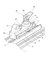
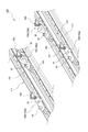
- FIG. 1 is a perspective view illustrating a configuration example of a seat movement fixing device according to a first embodiment.
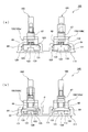
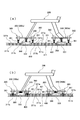
- FIG. 2 is a front view for explaining the seat movement fixing device according to the first embodiment.
- FIG. 3 is a perspective view illustrating a configuration example of a main part of the seat moving fixing device for the front leg according to the first embodiment.
- FIG. 4 is a perspective view showing a configuration example of a main part of the seat movement fixing device for the rear leg according to the first embodiment.
- FIG. 5 is a partially broken perspective view illustrating the linear guide according to the first embodiment.
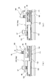
- FIG. 6 is a longitudinal sectional view showing a state in which the restraint between the leg mounting member for the front leg and the flange-shaped portion according to the first embodiment is released.
- FIG. 1 is a perspective view illustrating a configuration example of a seat movement fixing device according to a first embodiment.
- FIG. 2 is a front view for explaining the seat movement fixing device according to the first embodiment.
- FIG. 3 is
- FIG. 7 is a longitudinal sectional view showing a state in which the restraint between the leg mounting member for the front leg and the flange-shaped portion according to the first embodiment is realized.
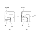
- FIG. 8 is a view for explaining the restraint / release state of the leg mounting member for the front leg and the flange-shaped portion according to the first embodiment, and a partial diagram (a) in FIG. It is a figure which shows the state by which the restraint state of the leg part attachment member for front side legs which concerns on 1st embodiment, and a flange shape part is cancelled
- FIG. 9 is a longitudinal sectional view showing a state in which the restraint between the leg mounting member for the rear leg and the flange-shaped portion according to the first embodiment is released.
- FIG. 10 is a longitudinal sectional view showing a state in which the restraint between the leg mounting member for the rear leg and the flange-shaped portion according to the first embodiment is realized.
- FIG. 11 is a view for explaining a restrained / released state of the leg mounting member for the rear leg and the flange-shaped portion according to the first embodiment.
- FIG. 11A is a partial view (a) in FIG. FIG.
- FIG. 11 is a view showing a state in which the restraint state between the leg mounting member for the rear leg and the flange-shaped portion according to the first embodiment is released, and FIG. It is a figure which shows the state by which the restraint state of the leg part attachment member and flange shape part for back side legs concerning one embodiment was realized.
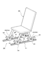
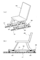
- FIG. 12 is a view illustrating a seat using the seat moving and fixing device according to the first embodiment.
- FIG. 12A is a perspective view
- FIG. b) is a side view illustrating the main part of the seat.
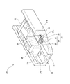
- FIG. 13 is a perspective view illustrating a configuration example of the seat movement fixing device according to the second embodiment.
- FIG. 14 is a diagram for explaining the seat movement fixing device according to the second embodiment.
- FIG. 12 is a view illustrating a seat using the seat moving and fixing device according to the first embodiment.
- FIG. 12A is a perspective view
- FIG. b) is a side view illustrating the main part of the seat.
- FIG. 14A is a front view of the seat movement fixing device according to the second embodiment.
- FIG. 14B is a rear view of the seat movement fixing device according to the second embodiment.
- FIG. 15 is a perspective view illustrating a state in which the restraint between the leg mounting member and the flange-shaped portion of the seat movement fixing device according to the second embodiment is realized.
- FIG. 16 is a view showing a state in which the restraint between the leg mounting member and the flange-shaped portion according to the second embodiment is realized, and
- FIG. 16A is a partial view (a) in the second embodiment. It is a front view which shows the state by which restraint with the said leg part attachment member and a flange shape part was implement
- FIG. 16 is the leg part attachment member and flange shape part which concern on 2nd embodiment. It is a rear view which shows the state by which restraint with was implement
- FIG. 17 is a partially broken perspective view illustrating the linear guide according to the second embodiment.
- FIG. 18 is a view for explaining a restrained / released state between the leg mounting member and the flange-shaped portion according to the second embodiment.
- FIG. 18A is a partial view (a) of the second embodiment.
- FIG. 19 is an enlarged view of a main part (portion indicated by a symbol ⁇ in the partial view (b) in FIG. 15) showing a state in which a restrained state between the leg mounting member and the flange-shaped part is released according to FIG.
- the part (b) is a main part showing a state in which the restraint state between the leg attachment member and the flange-shaped part according to the second embodiment is realized (reference numeral ⁇ in the part (b) in FIG. 17).
- FIG. 19 is a view for explaining a restraint state between the leg mounting member for the front leg and the flange-shaped portion according to the second embodiment.
- FIG. 19A is a partial view (a) of FIG. It is a longitudinal cross-sectional view which shows the state by which the restraint state of the leg part attachment member for front side legs and flange-shaped part which concerns on embodiment of this invention is cancelled
- FIG. 20 is a view for explaining a restrained state between the leg mounting member for the rear leg and the flange-shaped portion according to the second embodiment
- FIG. 20 is a longitudinal cross-sectional view which shows the state by which the restraint state of the leg part attachment member for rear side legs which concerns on 2nd embodiment, and a flange shape part is cancelled
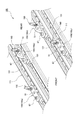
- FIG. 21 is a perspective view illustrating a configuration example of the seat movement fixing device according to the third embodiment.
- FIG. 22 is a view for explaining the seat movement fixing device according to the third embodiment, and FIG. 22 is a partial view (a) showing a state in which the restraint of the seat is released, FIG. 22B is a diagram showing a state in which seat restraint is executed.
- FIG. 23 is a view showing a modified example of the seat movement fixing device according to the third embodiment, wherein a partial view (a) in FIG. 23 shows an external perspective view of the device, and a partial view (b) shows the device. A side view is shown.
- FIG. 1 is a perspective view showing a configuration example of the seat movement fixing device according to the first embodiment
- FIG. 2 is a diagram for explaining the seat movement fixing device according to the first embodiment. It is a front view.
- FIG. 3 is a perspective view showing a configuration example of a main part of the seat movement fixing device for a front leg according to the first embodiment
- FIG. 4 is a rear leg according to the first embodiment. It is a perspective view which shows the example of a principal part structure of the moving fixing device for seats. Furthermore, FIG.
- FIG. 5 is a partially broken perspective view illustrating the linear guide according to the first embodiment.
- FIG. 6 is a longitudinal sectional view showing a state in which the restraint between the leg mounting member for the front leg and the flange-shaped portion according to the first embodiment is released, and FIG. 7 shows the first embodiment. It is a longitudinal cross-sectional view which shows the state by which restraint with the leg part attachment member for front side legs which concerns on a form, and a flange shape part was implement
- FIG. 8 is a view for explaining a restrained / released state between the leg mounting member for the front leg and the flange-shaped portion according to the first embodiment, and is a partial view (a) in FIG.
- FIG. 9 is a longitudinal sectional view showing a state in which the restraint between the leg mounting member for the rear leg and the flange-shaped portion according to the first embodiment is released, and FIG.
- FIG. 11 is a view for explaining a restrained / released state between the leg mounting member for the rear leg and the flange-shaped portion according to the first embodiment, and is a partial view (a) in FIG. ) Is a view showing a state in which the restraint state between the leg mounting member for the rear leg portion and the flange-shaped portion according to the first embodiment is released, and FIG. 11B is a partial view (b).
- FIG. 12 is a diagram illustrating a seat using the seat movement fixing device according to the first embodiment.
- FIG. 12A is a perspective view
- FIG. Part (b) is a side view illustrating the main part of the seat.
- the seat moving and fixing device 10 includes a long reference member 11 that is fixedly installed extending in the longitudinal direction of the seat installation surface,
- the leg 200 is fixedly installed between the leg mounting member 50, the long reference member 11, and the leg mounting member 50, and the leg is formed along the longitudinal direction of the long reference member 11.
- the linear guide 20 that enables the mounting member 50 to move horizontally, and a lock mechanism 60 that is fixedly installed on the leg mounting member 50 are configured.
- the reference member 11 is a long member fixedly installed on the seat installation surface, and is a member serving as a reference for the seat movement fixing device 10 according to the first embodiment.
- the cross-sectional shape of the reference member 11 is substantially U-shaped, and a seat 200 to be described later with respect to the substantially U-shaped internal space with the substantially U-shaped open portion facing upward.
- the front leg mechanism (for example, the leg mounting member 50a and the locking mechanism 60) and the rear leg mechanism (for example, the leg mounting member 50b and the locking mechanism 60) of the seat 200 are arranged in parallel. Are arranged.
- the leg attachment member 50 is configured such that the legs of the seat 200 are fixedly installed.
- the leg attachment members 50a for the front legs on which the front legs of the seat 200 are fixedly installed and the seat 200 are fixed.
- a lock mechanism 60 which will be described later, is fixedly installed on the leg mounting member 50 (50a, 50b).
- the leg attachment member 50 (50a, 50b) can be moved horizontally along the longitudinal direction of the long reference member 11.
- a linear guide 20 is installed.
- the linear guide 20 according to the present embodiment includes a track rail 21 as a track member, and a moving block 23 as a moving member attached to the track rail 21 via a plurality of balls 22 so as to be movable. And.
- the track rail 21 is a long member having a substantially U-shaped cross section. Load rolling grooves 21a capable of receiving the balls 22 are formed on both inner side surfaces of the track rail 21 over the entire length of the track rail 21. It is a track member of a type called a so-called outer rail.
- the track rail 21 is formed with a plurality of bolt mounting holes 21b at appropriate intervals in the longitudinal direction. The track rail 21 is fixed to the upper surface of the reference member 11 by bolts (not shown) screwed into the plurality of bolt mounting holes 21b.
- the moving block 23 is provided with two load rolling grooves 23a facing the load rails 21a in total on the left and right strips of the track rail 21, respectively.
- Two load rolling paths 25 are formed between the track rail 21 and the moving block 23 by the combination of the load rolling grooves 21a and 23a.
- the moving block 23 has two return passages 26 extending in parallel with the two load rolling paths 25.
- the moving block 23 has lid portions 28 at both end faces thereof, and a ball guide groove (not shown) formed in the lid portion 28 and recessed into an arch shape forms a gap between the load rolling path 25 and the return path 26.
- the direction change path 27 formed so as to project in an arch shape therebetween is formed.
- a direction changing path 27 that connects the load rolling path 25 and the return path 26 is formed between them.
- An unloaded rolling path 29 of the ball 22 is formed by the return path 26 and the direction changing path 27, and an infinite circulation path 30 is configured by a combination of the unloaded rolling path 29 and the loaded rolling path 25.
- the plurality of balls 22 are installed in the endless circulation path 30 so as to be capable of infinite circulation, so that the moving block 23 can reciprocate relative to the track rail 21.
- a locking shape portion 31 having a dovetail shape extending in the longitudinal direction is formed on the track rail 21 of the linear guide 20. (See FIG. 2, FIG. 5 etc.).
- This locking shape portion 31 is an essential component for exhibiting the movement / fixation function of the seat movement fixing device 10 by cooperating with a lock mechanism 60 described later.
- FIG. 2 FIG. 3, FIG. 6 to FIG. 8, the structure of the leg attachment member 50a and the lock mechanism 60, which are mechanisms for the front leg of the seat 200, will be described.
- the leg mounting member 50a is a member having a gate shape in appearance, and is a member disposed so as to straddle the moving block 23 of the linear guide 20.
- the leg attachment member 50a and the moving block 23 of the linear guide 20 are connected to each other through a bush 67 made of a soft material having a buffering function at a substantially central portion of the leg attachment member 50a and the moving block 23.
- a coil spring 68 is installed as an elastic body disposed so as to surround the bush 67.
- the coil spring 68 can exert a pressing force (elastic force).
- a lock mechanism 60 is installed on the leg mounting member 50a.
- the lock mechanism 60 according to the first embodiment is a rod housing 61 having a hollow hole, and a shaft-like member that is installed through the hollow hole of the rod housing 61, and has a flange-shaped portion 64 on one end side. And a rod member 63 having an operation lever portion 65 having a cam shape on the other end side.
- the rod housing 61 is for supporting and guiding the rod member 63, and a screw 62 for joining the rod housing 61 and the leg mounting member 50a is integrally formed. With this screw 62, the rod housing 61 is fixedly installed in a state in which it cannot move with respect to the leg mounting member 50a.
- the rod member 63 is a shaft-like member that is installed so as to be vertically movable with respect to the hollow hole of the rod housing 61, and has a flange-shaped portion 64 on the lower end side.
- an operation lever portion 65 having a cam shape is installed in a tiltable state.
- the cam shape of the operation lever portion 65 is configured to contact the upper end surface of the rod housing 61. Further, in the first embodiment, as shown in FIGS. 6 to 8, when the operation lever portion 65 is laid down and laid down, the protruding amount of the upper end portion of the rod member 63 protruding from the upper end surface of the rod housing 61.
- the cam shape increases so that the protruding amount of the upper end portion of the rod member 63 protruding from the upper end surface of the rod housing 61 increases.
- Is configured to act that is, in other words, when the operation lever portion 65 is tilted so as to be laid down, the amount of protrusion on the flange-shaped portion side of the rod member 63 protruding downward from the rod housing 61 increases, and the flange The distance between the shape portion 64 and the bottom surface of the leg mounting member 50a is increased, and the rod member that protrudes downward from the rod housing 61 when the operation lever portion 65 is raised and tilted to stand upright. 63, the protrusion amount on the flange-shaped portion side of 63 is reduced, and the distance between the flange-shaped portion 64 and the bottom surface of the leg mounting member 50a is reduced.
- the rod housing 61 is fixedly installed on the leg mounting member 50a, and the flange-shaped portion 64 of the rod member 63 is formed in the locking shape portion 31 having a cross-sectional dovetail shape. Since it is inserted and installed, when the operation lever portion 65 is tilted so as to be laid down by the action of the cam shape of the operation lever portion 65 described above, it protrudes downward from the rod housing 61. The amount of protrusion of the rod member 63 on the flange-shaped portion side increases, and the distance between the flange-shaped portion 64 and the bottom surface of the leg mounting member 50a increases.
- Such a state is a state shown in a partial diagram (a) in FIG. 8, and means that the restrained state between the leg mounting member 50 a pressing the vicinity of the locking shape portion 31 and the flange shape portion 64 is released. is doing.
- the operation lever portion 65 when the operation lever portion 65 is raised and tilted so as to be in an upright state, the protrusion amount on the flange shape portion side of the rod member 63 protruding downward from the rod housing 61 is reduced, and the flange shape The space
- Such a state is a state shown in a partial diagram (b) in FIG. 8, and means that a restrained state between the leg mounting member 50a pressing the vicinity of the locking shape portion 31 and the flange shape portion 64 is realized. is doing.
- the attachment position of the bush 67 which is a connection location with the movement block 23 is located in the approximate center part of the leg part attachment member 50a, and the locking mechanism 60 of the above-mentioned.
- the mounting position is set at a position close to one side of the gate shape that is off the center of the leg mounting member 50a. Therefore, the pressing force for restraining the leg mounting member 50a and the flange-shaped portion 64 that presses the vicinity of the locking shape portion 31 exerted by the action of the lock mechanism 60 is the portal shape of the leg mounting member 50a. It will act at a position close to one side.
- the bush 67 connecting the leg attachment member 50a and the moving block 23 is a rigid body without a buffering function, a smooth restraining / releasing operation cannot be performed due to the deterioration of the balance of the pressing force application. Therefore, in the first embodiment, the bush 67 is formed of a soft material having a buffer function. By configuring the bushing 67 connecting the leg attachment member 50a and the moving block 23 with a soft material having a buffering function, there is an allowance between the leg attachment member 50a and the moving block 23 when the restraint state is established. Therefore, the seat 200 can be fixed and moved by the seat movement fixing device 10 in a suitable and easy manner.
- the leg mounting member 50b is a member having a gate-like appearance and is disposed so as to straddle the moving block 23 of the linear guide 20.
- the leg attachment member 50b and the moving block 23 of the linear guide 20 are connected to each other through a bush 67 made of a soft material having a cushioning function at a substantially central portion of the leg attachment member 50b and the moving block 23.
- a coil spring 68 is installed as an elastic body disposed so as to surround the bush 67.
- the coil spring 68 can exert a pressing force (elastic force).
- the force acts in a direction in which the leg portion mounting member 50b and the moving block 23 are separated by the action of the elastic force of the coil spring 68.
- the state in which the leg mounting member 50b is lifted upward is maintained.
- the direction of the moving block 23 is caused by the downward pressing force against the elastic force of the coil spring 68.
- the leg attachment member 50b is moved toward the position, and the state where the leg attachment member 50b is pressed against the track rail 21 is maintained.
- a lock mechanism 60 is installed on the leg mounting member 50b.
- the lock mechanism 60 according to the first embodiment is a rod housing 61 having a hollow hole, and a shaft-like member that is installed through the hollow hole of the rod housing 61, and has a flange-shaped portion 64 on one end side. And a rod member 63 having an operation lever portion 65 having a cam shape on the other end side.
- the rod housing 61 is for supporting and guiding the rod member 63, and a screw 62 for joining the rod housing 61 and the leg mounting member 50b is integrally formed. With this screw 62, the rod housing 61 is fixedly installed in a state in which it cannot move with respect to the leg mounting member 50b.
- the rod member 63 is a shaft-like member that is installed so as to be vertically movable with respect to the hollow hole of the rod housing 61, and has a flange-shaped portion 64 on the lower end side.
- an operation lever portion 65 having a cam shape is installed in a tiltable state.
- the cam shape of the operation lever portion 65 is configured to contact the upper end surface of the rod housing 61. Further, in the first embodiment, as shown in FIGS. 9 to 11, when the operation lever portion 65 is tilted so as to be laid down, the rod member protrudes downward from the rod housing 61.
- the protrusion amount on the flange-shaped portion side of 63 increases, the distance between the flange-shaped portion 64 and the bottom surface of the leg mounting member 50b increases, and the operation lever portion 65 is raised and tilted so as to be in an upright state.
- the amount of protrusion of the rod member 63 protruding downward from the rod housing 61 on the flange-shaped portion side decreases, and the distance between the flange-shaped portion 64 and the bottom surface of the leg mounting member 50b decreases.
- the rod housing 61 is fixedly installed on the leg mounting member 50b, and the flange-shaped portion 64 of the rod member 63 is formed on the locking-shaped portion 31 having a cross-sectional dovetail shape. Since it is inserted and installed, when the operation lever portion 65 is tilted so as to be laid down by the action of the cam shape of the operation lever portion 65 described above, it protrudes downward from the rod housing 61. The protrusion amount of the rod member 63 on the flange-shaped portion side is increased, and the distance between the flange-shaped portion 64 and the bottom surface of the leg mounting member 50b is increased.
- This state is a state shown in the partial diagram (a) in FIG. 11 and means that the restrained state between the leg mounting member 50b and the flange-shaped portion 64 that presses the vicinity of the locking-shaped portion 31 is released. is doing.
- the operation lever portion 65 when the operation lever portion 65 is raised and tilted so as to be in an upright state, the protrusion amount on the flange shape portion side of the rod member 63 protruding downward from the rod housing 61 is reduced, and the flange shape The space
- Such a state is a state shown in a partial diagram (b) in FIG. 11, and means that a restrained state between the leg attachment member 50 b and the flange shape portion 64 that presses the vicinity of the locking shape portion 31 is realized. is doing.
- the leg mounting member 50b according to the first embodiment is positioned with respect to the side of the leg mounting member 50b facing the track rail 21, as shown in more detail in FIG.
- the pin-shaped portion 53 is formed.
- a plurality of positioning holes 33 into which the pin-shaped portions 53 of the leg mounting member 50b can be inserted are formed at predetermined intervals on the surface of the track rail 21 of the linear guide 20 facing the leg mounting member 50b.
- the positioning holes 33 according to the first embodiment are formed at equal intervals, for example, 1 inch pitch, on the central bottom surface of the locking shape portion 31 having a cross-sectional dovetail shape.
- the leg mounting member 50 b can be positioned by fitting the pin-shaped portion 53 and the positioning hole 33. That is, by using the pin-shaped portion 53 and the positioning hole 33, the seat 200 attached to the leg attachment member 50b can be positioned accurately and easily.
- the leg mounting member 50 b connected to the seat 200 is moved along the track rail 21 by the action of the linear guide 20. Moving. At this time, a position where the pin-shaped portion 53 and the positioning hole 33 can be fitted, that is, a positioning position of the seat 200 at a pitch of 1 inch, is searched by moving the leg mounting member 50b while slightly pushing it downward. It becomes possible.
- the desired seat positioning position is determined, the downward pressing force against the action of the elastic force of the coil spring 68 is obtained by causing the locking mechanism 60 to function and applying a downward pressing force to the leg mounting member 50b.
- leg attachment member 50b moves toward the track rail 21 (moving block 23), the pin-shaped part 53 and the positioning hole 33 are fitted and positioned, and the leg part is attached.
- the member 50b is pressed against the track rail 21, and the restraint state between the leg mounting member 50b pressing the vicinity of the locking shape portion 31 and the flange shape portion 64 is realized.
- the attachment position of the bush 67 which is a connection location with the movement block 23 is located in the approximate center part of the leg part attachment member 50b, and the locking mechanism 60 of the above-mentioned.
- the mounting position is set at a position close to one side of the gate shape that is off the center of the leg mounting member 50b. Accordingly, the pressing force for restraining the leg mounting member 50b and the flange-shaped portion 64 that presses the vicinity of the locking shape portion 31 exerted by the action of the lock mechanism 60 is the portal shape of the leg mounting member 50b. It will act at a position close to one side.
- the bush 67 connecting the leg attachment member 50b and the moving block 23 is a rigid body without a buffering function, a smooth restraining / releasing operation cannot be performed due to the deterioration of the balance of the pressing force application. Therefore, in the first embodiment, the bush 67 is formed of a soft material having a buffer function. By configuring the bush 67 connecting the leg attachment member 50b and the moving block 23 with a soft material having a buffering function, a play allowance is provided between the leg attachment member 50b and the moving block 23 when the restraint state is established. Therefore, the seat 200 can be fixed and moved by the seat movement fixing device 10 in a suitable and easy manner.
- the restrained state of the leg mounting member 50b and the flange-shaped portion 64 that presses the vicinity of the locking-shaped portion 31 performed by the function of the lock mechanism 60 realizes a very stable fixed state. Therefore, even when the pin-shaped portion 53 and the positioning hole 33 are fitted, for example, a lateral force or the like that destroys the pin-shaped portion 53 is not applied.
- the apparatus configuration of the seat movement fixing apparatus 10 according to the first embodiment can realize a stable movement / fixing operation and also a long life of the apparatus.
- the pin-shaped portion 53 for positioning is formed only on the leg mounting member 50b for the rear leg of the seat 200, and the leg for the front leg of the seat 200 is formed.
- the mounting member 50a is not formed.
- Such a configuration is adopted because if the positioning function is exerted on both the front and rear legs of the seat 200, it is difficult to perform stable and reliable positioning due to the formation error of the positioning hole 33, the error of the device, and the like. Therefore, the fitting of the pin-shaped portion 53 for positioning the seat 200 and the positioning hole 33 may be only one of the front and rear. Therefore, in the first embodiment described above, the pin-shaped portion 53 for positioning is formed only on the leg mounting member 50b for the rear leg of the seat 200. May be formed only on the leg mounting member 50a for the front leg of the seat 200.
- the seat moving / fixing device 10 according to the first embodiment has been described above. According to the seat movement fixing device 10 according to the first embodiment described above, it is possible to receive downward force (that is, radial force) by the leg mounting members 50a and 50b, and upward by the flange-shaped portion 64.
- the pin-shaped portion 53 can exert the role of positioning and braking with respect to the moving force in the front-rear direction (that is, the force in the sliding direction).
- the seat movement fixing device 10 according to the first embodiment is linear when no seat is on the seat 200 and the restraint state of the device is released.
- the guide 20 functions for light slide movement.
- the leg mounting members 50a and 50b and the flange-shaped portion 64 cooperate with each other in the radial and reverse radial directions, that is, the seat.
- An external load applied to 200 can be suitably received. That is, in the first embodiment, the linear guide 20 does not need to take charge of an external load and only needs to function for sliding movement, so that the linear guide 20 can be downsized. This effect is particularly effective in the field of aircraft. In the case of an aircraft seat 200, it is assumed that a high acceleration of several G is applied while a certain amount of load is placed on the seat 200. If the design can withstand such a situation, the linear guide generally has to be large. However, according to the seat moving and fixing device 10 according to the first embodiment, the linear guide 20 does not need to handle an external load, so the linear guide 20 can be downsized, and as a result, the device can be downsized. It has been realized.
- the seat moving and fixing device 10 can be used by installing, for example, an aircraft seat 200 as shown in FIG. Specifically, the front foot of the seat 200 is fixed to the leg mounting hole 51 formed in the leg mounting member 50a for the front leg of the seat 200 using a known fastening means such as a bolt, and the seat The movement of the seat is fixed by fixing the rear leg of the seat 200 to a leg mounting hole 51 formed in the leg mounting member 50b for the rear leg 200 using a known fastening means such as a bolt. The installation of the seat 200 to the device 10 is completed.
- the restraint state is released by tilting the operation lever portion 65 so as to be in a lying state, and the seat 200 can be moved by applying a force in the front-rear direction. It becomes possible. Further, by searching the position where the pin-shaped portion 53 and the positioning hole 33 can be fitted, that is, the positioning position of the seat 200 at 1 inch pitch, by moving the leg mounting member 50b slightly while pushing downward. Can do.
- the positioning position of the seat 200 is determined, the restraint state is realized while the positioning is performed by tilting the operation lever portion 65 so that the seat 200 is in the upright state. By performing such an operation, the seat 200 can be moved and fixed easily and quickly. That is, according to the first embodiment, it is possible to provide the seat movement fixing device 10 that can move and fix the seat 200 easily and quickly.
- the first embodiment as a preferred application example of the present invention has been described above.
- the seat movement fixing device 100 according to the second embodiment having a different form from the first embodiment will be described.
- FIG. 13 is a perspective view showing a configuration example of the seat movement fixing device according to the second embodiment
- FIG. 14 is a diagram for explaining the seat movement fixing device according to the second embodiment.
- FIG. 14 is a front view of a seat movement fixing device according to the second embodiment
- FIG. 14B is a front view of the second embodiment. It is a rear view of the moving fixing device for seats.
- FIG. 15 is a perspective view showing a state in which the restraint between the leg mounting member and the flange-shaped portion of the seat movement fixing device according to the second embodiment is realized
- FIG. 16 is the second embodiment.
- FIG. 16 It is a figure which shows the state by which the restraint of the leg part attachment member which concerns on a form, and a flange shape part was implement
- the fractional view (a) in FIG. 16 is a leg part attachment member and flange shape which concern on 2nd embodiment. It is a front view which shows the state by which restraint with the part was implement
- the fractional drawing (b) in FIG. 16 is the state by which restraint with the leg part attachment member and flange-shaped part which concern on 2nd embodiment was implement
- FIG. 18 is a figure for demonstrating the restraint / release state of the leg part attachment member and flange-shaped part which concern on 2nd embodiment, and the fractional figure (a) in FIG.
- FIG. 16 is an enlarged view of a main part (portion indicated by a symbol ⁇ in the fractional view (b) in FIG. 15) showing a state in which the restraint state between the leg mounting member and the flange-shaped portion according to the embodiment is released;
- FIG. 18B is a main part showing a state in which the restraint state between the leg mounting member and the flange-shaped portion according to the second embodiment is realized (in FIG. 17B).
- FIG. 7 is an enlarged view of a portion indicated by a symbol ⁇ .
- FIG. 16 is an enlarged view of a main part (portion indicated by a symbol ⁇ in the fractional view (b) in FIG. 15) showing a state in which the restraint state between the leg mounting member and the flange-shaped portion according to the embodiment is
- FIG. 19 is a figure for demonstrating the restraint state of the leg part attachment member for front side legs which concerns on 2nd embodiment, and a flange shape part
- the fractional figure (a) in FIG. It is a longitudinal cross-sectional view which shows the state by which the restraint state of the leg part attachment member for front side legs which concerns on 2nd embodiment, and a flange shape part is cancelled
- the fractional view (b) in FIG. It is a longitudinal cross-sectional view which shows the state by which the restraint state of the leg part attachment member for front side legs which concerns on 2nd embodiment, and a flange shape part is implement
- FIG. 20 is a figure for demonstrating the restraint state of the leg part attachment member for rear side legs which concerns on 2nd embodiment, and a flange shape part
- FIG. 20 is a longitudinal sectional view showing a state in which the restrained state between the leg mounting member for the rear leg and the flange-shaped portion according to the second embodiment is released
- FIG. FIG. 5 is a longitudinal sectional view showing a state in which a restrained state between a leg mounting member for a rear leg and a flange-shaped portion according to a second embodiment is realized.
- symbol is attached
- the locking shape portion 31 having a dovetail shape extending in the longitudinal direction is formed on the track rail 21 of the linear guide 20.
- the case has been described as an example.
- the locking shape portion having a cross-sectional dovetail shape can also be formed on a long reference member.
- the locking shape portion 131 according to the second embodiment is shown in detail in FIGS.
- the seat movement fixing device 100 is a long reference member 111 that is fixedly installed extending in the longitudinal direction of the seat installation surface. And a leg attachment member 150 fixedly installed on the leg portion of the seat 200, and the long reference member 111 and the leg attachment member 150, and is attached along the longitudinal direction of the long reference member 111.
- the linear guide 120 that enables the leg attachment member 150 to move horizontally, and a lock mechanism 160 that is fixedly installed on the leg attachment member 150 are configured.
- the reference member 111 is a long member fixedly installed on the seat installation surface, and is a member serving as a reference for the seat movement fixing device 100 according to the second embodiment. As shown in FIGS. 13 to 16, the reference member 111 has a substantially L-shaped wall portion standing upright to form a locking shape portion 131 having a cross-sectional dovetail shape extending in the longitudinal direction. Is formed. In the second embodiment, a configuration in which two rows of locking shape portions 131 are formed with respect to one reference member 111 is illustrated, and one of the two rows of locking shape portions 131 is the front side of the seat 200. The other is for the leg and the other is for the rear leg of the seat 200.
- the engaging shape portion 131 is indispensable for exerting the moving / fixing function of the seat moving / fixing device 100 by cooperating with a lock mechanism 160 described later. Further, a mechanism for a front leg of the seat 200 described later (for example, a leg attachment member 150a, a lock mechanism 160, etc.) and a rear leg of the seat 200 are provided in each of the two rows of locking shape portions 131. Mechanism (for example, the leg attachment member 150b, the lock mechanism 160, etc.) are respectively disposed.
- the leg attachment member 150 is configured such that the legs of the seat 200 are fixedly installed.
- the leg attachment members 150a for the front legs to which the front legs of the seat 200 are fixedly installed and the seat 200 are fixed.
- a lock mechanism 160 which will be described later, is fixedly installed on the leg mounting member 150 (150a, 150b).
- the leg attachment member 150 (150a, 150b) can be horizontally moved along the longitudinal direction of the long reference member 111.
- a linear guide 120 is installed. As shown in FIG. 17, the linear guide 120 according to the present embodiment includes a track rail 121 as a track member, and a moving block 123 as a moving member that is movably attached to the track rail 121 via a plurality of balls 122. And.
- the track rail 121 is a long member having a substantially rectangular cross section, and load rolling grooves 121a capable of receiving the balls 122 are formed on the outer circumferential side surfaces of the track rail 121 over the entire length of the track rail 121. Yes.
- a plurality of bolt mounting holes 121b are formed in the track rail 121 at appropriate intervals in the longitudinal direction.
- the track rail 121 is fixed inside the locking shape portion 131 formed in the reference member 111 by bolts (not shown) screwed into the plurality of bolt mounting holes 121b.
- the moving block 123 is provided with two load rolling grooves 123a opposed to the total two load rolling grooves 121a, one on each side of the track rail 121.
- Two load rolling paths 125 are formed between the track rail 121 and the moving block 123 by the combination of the load rolling grooves 121a and 123a.
- two return passages 126 extending in parallel with the two load rolling paths 125 are formed in the moving block 123.
- the moving block 123 has lid portions 128 on both end faces thereof, and a ball guide groove (not shown) formed in the lid portion 128 and recessed in an arch shape forms a load rolling path 125 and a return path 126.
- a direction change path (not shown) formed so as to project in an arch shape therebetween is formed.
- the lid 128 is securely fixed as a member constituting the end of the moving block 123, whereby a direction change path (not shown) connecting the load rolling path 125 and the return path 126 is formed therebetween.
- An unloaded rolling path of the ball 122 is formed by the return path 126 and the direction changing path (not shown), and an infinite circulation path is configured by a combination of the unloaded rolling path and the loaded rolling path 125.
- the plurality of balls 122 are installed in an infinite circulation path so as to be capable of infinite circulation, so that the moving block 123 can reciprocate relative to the track rail 121.
- leg mounting member 150 150a, 150b
- lock mechanism 160 the structure of the leg mounting member 150 (150a, 150b) and the lock mechanism 160 will be described.
- the leg attachment members 150a and 150b are members each having a substantially T-shaped appearance in a side view, and one umbrella portion having a substantially T-shape is disposed above the moving block 123 of the linear guide 120. It is a member arrange
- the leg attachment members 150a and 150b and the moving block 123 of the linear guide 120 include a bush 67 made of a soft material having a buffering function at the ends of the leg attaching members 150a and 150b and the substantially central portion of the moving block 123.
- a coil spring 68 as an elastic body disposed so as to surround the bush 67 is installed between the leg mounting members 150a and 150b and the moving block 123 of the linear guide 120. .
- the coil spring 68 can exert a pressing force (elastic force). Therefore, in a normal case where the leg attachment members 150a and 150b do not receive external force, the force acts in the direction in which the leg attachment members 150a and 150b and the moving block 123 are separated by the action of the elastic force of the coil spring 68. The state where the leg attachment members 150a and 150b are lifted upward with respect to the moving block 123 is maintained. On the other hand, when a downward pressing force acts on the leg attachment members 150a and 150b by the function of the lock mechanism 160 described later, the moving block 123 is acted on by the downward pressing force against the elastic force of the coil spring 68. The leg attachment members 150a and 150b are moved in the direction of, and the leg attachment members 150a and 150b are kept pressed against the reference member 111.
- a pressing force elastic force
- a lock mechanism 160 is installed on the leg attachment members 150a and 150b.
- the lock mechanism 160 according to the second embodiment is a rod housing 61 having a hollow hole, and a shaft-like member that is installed through the hollow hole of the rod housing 61, and has a flange-shaped portion 64 on one end side.
- the lock mechanism 160 according to the second embodiment has substantially the same structure as the lock mechanism 60 according to the first embodiment described above.
- the locking mechanism 160 according to the embodiment is different from the locking mechanism 60 according to the first embodiment in that the cam shape formed in the operation lever portion 65 is different. That is, as shown in FIGS. 19 and 20 and the like, in the case of the second embodiment, when the operation lever portion 65 is raised and tilted so as to be in an upright state, the restraint is released. When the operation lever portion 65 is tilted so as to be in a lying state, the restraint is set to be executed. That is, in the case of the second embodiment, as shown in FIG.
- the flange-shaped portion 64 of the rod member 63 is inserted and installed in the engaging shape portion 131 having a cross-sectional dovetail shape, and the appearance is substantially T-shaped in a side view.
- the leg attachment members 150a and 150b are substantially n-shaped in a front view (back view) and are formed in a gate shape with a long leg. Therefore, as shown in FIG. 14, the flange-shaped part 64 and the leg attachment member When the space between the bottom surfaces of 150a and 150b is reduced, the pressing force between the flange-shaped portion 64 and the leg mounting members 150a and 150b from the inside to the outside of the locking-shaped portion 131 is released, and as a result, the restraint is restricted.
- the flange shape of the rod member 63 that protrudes downward from the rod housing 61 when the operation lever portion 65 is tilted so as to be brought upright by the action of the cam shape of the operation lever portion 65.
- the protrusion amount on the part side increases, and the distance between the flange-shaped part 64 and the bottom surfaces of the leg mounting members 150a and 150b decreases, so that both the members 150 (150a and 150b) and 64 are connected to the locking-shaped part 131.
- the press will be released.
- This state is the state shown in FIG. 14, and the leg mounting members 150 a and 150 b that press the inner wall surface of the locking shape portion 131 and the flange shape portion 64 are directed inward from the inner wall surface of the locking shape portion 131.
- the function of the bush 67 formed of a soft material having a buffer function and the function of the linear guide 120 responsible for the moving force are the same as in the case of the first embodiment described above. Therefore, it can be said that the apparatus configuration of the seat moving / fixing apparatus 100 according to the second embodiment also realizes stable movement / fixing operation and extends the life of the apparatus.
- the leg mounting member 150b according to the second embodiment is also provided with a leg mounting member 150b for the rear leg on which the rear leg of the seat 200 is fixedly installed, as in the case of the first embodiment.
- a pin-shaped portion 53 for positioning is formed. As shown in FIG. 20, the pin-shaped portion 53 is formed on the side of the leg mounting member 150b facing the reference member 111.
- the pin-shaped portion 53 is formed on the bottom surface inside the locking shape portion 131 of the reference member 111, positioning so that the pin shape portion 53 included in the leg portion mounting member 150b can be fitted so as to avoid the installation position of the track rail 121 included in the linear guide 120.
- a plurality of holes 133 are formed at predetermined intervals.
- the positioning holes 133 according to the second embodiment are formed at equal intervals, for example, at a pitch of 1 inch, on the bottom surface of the locking shape portion 131 having a dovetail cross-sectional shape. Then, by positioning the pin-shaped portion 53 and the positioning hole 133, the leg mounting member 150b can be positioned. That is, by using the pin-shaped portion 53 and the positioning hole 133, the seat 200 attached to the leg attachment member 150b can be positioned accurately and simply.
- the leg mounting members 150a and 150b connected to the seat 200 are moved by the action of the linear guide 120 to the track rail 121. Move along. At this time, the leg mounting member 150b is moved while being pushed slightly downward to find a place where the pin-shaped portion 53 and the positioning hole 133 can be fitted, that is, a positioning position of the seat 200 at a pitch of 1 inch. It becomes possible.
- the downward pressing force against the action of the elastic force of the coil spring 68 is achieved by causing the lock mechanism 160 to function and applying a downward pressing force to the leg attachment members 150a and 150b.
- the leg mounting member 150b moves in the direction of the reference member 111 (moving block 123), and the pin-shaped portion 53 and the positioning hole 133 are fitted to perform positioning.
- the portion mounting members 150a and 150b are pressed against the reference member 111, and the restraint state between the leg mounting members 150a and 150b and the flange-shaped portion 64 that press the inner wall surface of the locking-shaped portion 131 outward is realized. Will be.
- the pin-shaped portion 53 for positioning is formed only on the leg mounting member 150b for the rear leg of the seat 200 as in the case of the first embodiment. It is not formed on the leg mounting member 150a for the leg (see FIG. 19).
- Such a configuration is adopted because if the positioning function is exerted on both the front and rear legs of the seat 200, stable and reliable positioning becomes difficult due to the formation error of the positioning hole 133 and the error of the device. Therefore, the fitting between the pin-shaped portion 53 for positioning the seat 200 and the positioning hole 133 may be only one of the front and rear. Therefore, in the second embodiment described above, the pin-shaped portion 53 for positioning is formed only on the leg mounting member 150b for the rear leg of the seat 200. May be formed only on the leg mounting member 150a for the front leg of the seat 200.
- the first embodiment is basically the same as the second embodiment. Therefore, the seat moving / fixing device 100 according to the second embodiment can realize a stable movement / fixing operation, and can also extend the life of the device.
- the seat movement fixing device 100 according to the second embodiment described above can be used by installing an aircraft seat 200 as shown in FIG. 12 as in the case of the first embodiment. . Therefore, according to the second embodiment, it is possible to provide the seat movement fixing device 100 that can move and fix the seat 200 easily and quickly.
- the locking shape portion 31 having a cross-sectional dovetail shape, the rod housing 61 having a hollow hole, and the shaft shape installed through the hollow hole of the rod housing 61 are provided.
- the moving and fixing device for a seat according to the present invention can be applied to forms other than the configuration including the locking shape portion 31 having a dovetail cross-sectional shape and the lock mechanisms 60 and 160 described above.
- FIG. 21 and FIG. 22 the seat movement fixing device 300 according to the third embodiment having a different form from the first and second embodiments will be described. To do.
- FIG. 21 is a perspective view showing a configuration example of the seat movement fixing device according to the third embodiment.
- FIG. 22 is a figure for demonstrating the movement fixing apparatus for seats which concerns on 3rd embodiment, and the fraction (a) in FIG. 22 is a figure which shows the state by which restraint of the seat was cancelled
- FIG. 22B is a diagram showing a state in which the restraint of the seat is executed.
- symbol is attached
- the seat movement fixing device 300 includes a long reference member 311 that extends in the longitudinal direction of the seat installation surface and is fixedly installed, and a leg mounting member that fixes and installs the legs of the seat 200. 350, a linear guide 320 that is attached between the long reference member 311 and the leg attachment member 350, and that allows the leg attachment member 350 to move horizontally along the longitudinal direction of the long reference member 311; And a locking mechanism 360 fixedly installed on the leg mounting member 350.
- the reference member 311 is a long member fixedly installed on the seat installation surface, and is a member serving as a reference for the seat movement fixing device 300 according to the third embodiment. As shown in FIG. 22, the reference member 311 is formed with a plurality of mounting holes 311a and 311b having a predetermined interval in the longitudinal direction.
- the attachment hole indicated by reference numeral 311 a is a screw hole used for fixing the connection with the track rail 321 constituting the linear guide 320
- the attachment hole indicated by reference numeral 311 b is the lock mechanism 360. It is a screw hole used for connection fixation with the attachment fixing bolt 361 which comprises.
- the leg mounting member 350 is configured such that the leg of the seat 200 is fixedly installed.
- the leg mounting member 350a for the front leg on which the front leg of the seat 200 is fixedly installed, and the seat The leg mounting member 350b for the rear leg on which the rear leg 200 is fixedly installed has the same configuration.
- the leg mounting member 350 (350a, 350b) according to the third embodiment is configured to have a portal shape, and the longitudinal direction of the reference member 311 and the track rail 321 is the longitudinal direction of the slide movement direction.
- a pair of lock mechanisms 360 are provided on both sides in the direction.
- a linear guide 320 is installed.
- the linear guide 320 according to this embodiment is of the same type as the linear guide 120 shown in FIG. 17, and is attached to the track rail 321 as a track member and the track rail 321 via a plurality of balls 122 so as to be movable.
- a moving block 323 as a moving member.
- the track rail 321 is an elongate member having a substantially rectangular cross section, and load rolling grooves 121a capable of receiving the balls 122 are formed on both sides of the outer periphery of the track rail 321 over the entire length of the track rail 121. Yes.
- a plurality of bolt mounting holes 321a and opening holes 321b are formed in the track rail 321 at appropriate intervals in the longitudinal direction.
- the opening hole 321b formed in the track rail 321 is a hole for inserting the mounting fixing bolt 361 included in the lock mechanism 360, and as shown in a partial diagram (b) in FIG.
- the mounting fixing bolt 361 provided is inserted into the opening hole 321b formed in the track rail 321 and screwed into the mounting hole 311b formed in the reference member 311 so that the reference member 311 and the leg mounting member 350 (350a, 350a, 350b) is realized.
- a coil spring 368 as an elastic body is installed with respect to the substantially center position of the portal shape, and this coil spring 368 is:
- the leg attachment member 350 (350a, 350b) and the moving block 323 are connected.
- the coil spring 368 can exert a pressing force (elastic force). Therefore, as shown in the partial diagram (a) in FIG. 22, when the restraint of the leg attachment member 350 (350a, 350b) is released, the leg attachment member is acted upon by the elastic force of the coil spring 368.
- the mounting fixing bolt 361 included in the locking mechanism 360 is formed on the track rail 321 in a state where the locking mechanism 360 functions, that is, a downward pressing force against the action of the elastic force of the coil spring 368 is applied to the seat 200 side.
- the fixed state of the reference member 311 and the leg attachment member 350 (350a, 350b) can be realized by being inserted into the opening hole 321b and screwed into the attachment hole 311b formed in the reference member 311. it can. That is, as shown in the partial diagram (b) in FIG. 22, it is possible to realize a state in which the leg mounting member 350 (350a, 350b) is restrained.
- this restraint state is implement
- the gate-shaped leg mounting members 350 (350 a, 350 b) are located with respect to the upper surface of the track rail 321. Since the gate-shaped leg portion is pressed, this state also contributes to realizing a stable fixed state between the reference member 311 and the leg mounting member 350 (350a, 350b).
- the seat moving and fixing device 300 according to the third embodiment has been described as various forms that the present invention can take. As with the case of the first and second embodiments, the seat movement fixing device 300 according to the third embodiment can move and fix the seat 200 easily and quickly.
- the seat 200 may have any number of legs, and the seat movement according to the number of legs What is necessary is just to change the structure of the fixing devices 10 and 100.
- leg mounting member 150a for the front leg of the seat 200 and the leg mounting member 150b for the rear leg are arranged in parallel.
- the scope of the present invention is not limited to the configuration of the parallel arrangement, and the leg mounting member 150a for the front leg of the seat 200 and the leg mounting member 150b for the rear leg are arranged in series. It is also possible to adopt a configuration.
- the shape of the leg mounting member 150 (150a, 150b), the mounting position of the lock mechanisms 60, 160 with respect to the leg mounting member 150 (150a, 150b), the formation position and shape of the pin-shaped portion 53, etc. In the range which can exhibit the same effect as each embodiment mentioned above, it can change suitably.
- the operation lever portion 65 when the cam shape of the operation lever portion 65 is changed as appropriate, the operation lever portion 65 is tilted so that the operation lever portion 65 is laid down and laid down. It was shown that either the restraint execution state or the restraint release state can be selected when it is tilted so as to be in the upright state. In other words, whether the restraint state is established when the operation lever portion 65 is tilted or whether the restraint state is established when the operation lever portion 65 is raised depends on the conditions of the place where the seat moving fixing device according to the present invention is installed, etc. It is possible to select arbitrarily according to.
- the leg attachment members 150 (150a, 150b) and 350 (350a, 350b) are individually installed for each leg part before and after the seat 200.
- the leg attachment member according to the present invention can be formed so as to be bridged over a plurality of legs of the seat 200.
- FIG. 23 is a figure which shows the modification of the movement fixing device for seats which concerns on 3rd embodiment
- the parting figure (a) in FIG. 23 shows the external appearance perspective view
- a wider range of the upper surface of the track rail 321 can be obtained by adopting a leg attachment member 450 that extends in the longitudinal direction so as to be bridged between the front and rear legs of the seat 200.
- the leg mounting member 450 can be pressed. Therefore, by adopting the configuration illustrated in FIG. 23, it is possible to realize a more stable fixing state of the leg mounting member 450 with respect to the reference member 311.
- the seat movement fixing device 10 100, 300 according to each of the above-described embodiments, the case where the aircraft seat 200 as shown in FIG.
- the application range of the seat moving fixing device is not limited to the field of aircraft.
- any place, means, building, etc. that can be effectively obtained by moving and fixing the seat 200 easily and quickly such as transport means other than airplanes such as large buses, and accommodation facilities such as theaters, movie theaters, and gymnasiums.
- the seat movement fixing device according to the present invention can be applied.
- a large number of bolt mounting holes 321a, opening holes 321b, and mounting holes 311a are formed with respect to the track rail 321 and the reference member 311. , 311b.
- these hole shapes may be provided according to the fixing interval of the seat moving fixing device, and it is not always necessary to provide the interval and the number as illustrated.
- the installation intervals and the number of installation of the bolt attachment holes 321a, the opening holes 321b, and the attachment holes 311a and 311b can be arbitrarily changed.
Abstract
座席用移動固定装置10は、座席設置面の長手方向に延びて固定設置される長尺の基準部材11と、座席の脚部を固定設置される脚部取付部材50aと、長尺の基準部材11と脚部取付部材50aとの間に取り付けられ、長尺の基準部材11の長手方向に沿って脚部取付部材50aを水平移動可能とするリニアガイド20と、脚部取付部材50aに固定設置されるロック機構60と、を備える。そして、脚部取付部材50aとリニアガイド20との間には、押圧力を発揮する弾性体としてのコイルバネ68が設置されている。この様な構成を備えることにより、座席用移動固定装置10は、座席200を容易かつ迅速に移動および固定することができる。
Description
本発明は、座席用移動固定装置に関するものである。
一般的に、航空機や大型バスなどの輸送手段においては、乗客が着席する座席は予め固定されている。したがって、輸送手段を運営する運営会社は、予め決められた座席数に応じて顧客に搭乗券や乗車券を販売しなければならないという営業上の制約が存在していた。
しかしながら、航空機や大型バスなどの輸送手段において、搭乗率や乗車率に応じて座席の前後の距離を変更することができれば、より多様化したサービスを提供することが可能となる。例えば、搭乗率や乗車率が高い場合には、より多くの乗客に当該輸送手段を利用してもらうために、座席の前後の距離を小さくすることで、一機の航空機又は一台の大型バスで収容できる乗客数を増加させることができる。これにより、輸送需要が多い繁忙期において、これまで他の輸送手段に流れていた顧客を獲得することができる。また例えば、搭乗率や乗車率が低い場合には、座席の前後の距離を大きくすることで、快適性を向上した座席を用意することができるので、輸送需要が少ない閑散期であっても座席の価値を向上することで乗客一人当たりの単価を向上させることができる。このように、従来の輸送手段においては、乗客に利用してもらう座席の前後の距離を小さくしたり、反対に座席の前後の距離を大きくしたりすることで、様々な状況に応じて最適なサービスを提供することのできる座席用移動固定装置の実現が望まれていた。
そして、この種の技術に関連する内容を開示するものとして、例えば、下記の特許文献1が存在している。下記の特許文献1には、航空機の座席シートを移動するために用いられる座席シートの移動方法が開示されている。
しかしながら、上掲の特許文献1に記載の座席シートの移動方法は、座席シートを移動するときに、ジャッキ装置やアダプタ部材などの多くの部材や座席シートを移動するための多くの工程を必要としており、座席シートの移動のために多大な手間が掛かるという課題が存在していた。
すなわち、上掲した特許文献1には、航空機の座席シートを移動させるという発想自体は開示されているものの、座席シートを容易かつ迅速に移動又は固定するための手段が全く開示されていない。したがって、上掲した特許文献1に開示された技術方法は、一般的に分単位で運行される輸送手段に対して実際に適用できるものではないと言わざるを得ないものである。
本発明は、上述した従来技術に存在する課題に鑑みて成されたものであり、その目的は、航空機や大型バスなどの輸送手段に用いられる座席を容易かつ迅速に移動および固定することができる座席用移動固定装置を提供することにある。
本発明に係る座席用移動固定装置は、座席設置面の長手方向に延びて固定設置される長尺の基準部材と、座席の脚部を固定設置される脚部取付部材と、前記長尺の基準部材と前記脚部取付部材との間に取り付けられ、前記長尺の基準部材の長手方向に沿って前記脚部取付部材を水平移動可能とするリニアガイドと、前記脚部取付部材に固定設置されるロック機構と、を備える座席用移動固定装置であって、前記脚部取付部材と前記リニアガイドとの間に、押圧力を発揮する弾性体が設置されていることを特徴とするものである。
本発明によれば、座席を容易かつ迅速に移動および固定することができる座席用移動固定装置を提供することができる。
以下、本発明を実施するための好適な実施形態について、図面を用いて説明する。なお、以下の各実施形態は、各請求項に係る発明を限定するものではなく、また、各実施形態の中で説明されている特徴の組み合わせの全てが発明の解決手段に必須であるとは限らない。
[第一の実施形態に係る座席用移動固定装置10]
まず、第一の実施形態に係る座席用移動固定装置10の構成例について、図1ないし図12を用いて説明する。ここで、図1は、第一の実施形態に係る座席用移動固定装置の構成例を示す斜視図であり、図2は、第一の実施形態に係る座席用移動固定装置を説明するための正面図である。また、図3は、第一の実施形態に係る前側脚部用の座席用移動固定装置の要部構成例を示す斜視図であり、図4は、第一の実施形態に係る後側脚部用の座席用移動固定装置の要部構成例を示す斜視図である。さらに、図5は、第一の実施形態に係るリニアガイドを例示する部分破断斜視図である。また、図6は、第一の実施形態に係る前側脚部用の脚部取付部材とフランジ形状部との拘束が解除された状態を示す縦断面図であり、図7は、第一の実施形態に係る前側脚部用の脚部取付部材とフランジ形状部との拘束が実現された状態を示す縦断面図である。さらに、図8は、第一の実施形態に係る前側脚部用の脚部取付部材とフランジ形状部との拘束/解除状態を説明するための図であり、図8中の分図(a)は、第一の実施形態に係る前側脚部用の脚部取付部材とフランジ形状部との拘束状態が解除されている状態を示す図であり、図8中の分図(b)は、第一の実施形態に係る前側脚部用の脚部取付部材とフランジ形状部との拘束状態が実現された状態を示す図である。また、図9は、第一の実施形態に係る後側脚部用の脚部取付部材とフランジ形状部との拘束が解除された状態を示す縦断面図であり、図10は、第一の実施形態に係る後側脚部用の脚部取付部材とフランジ形状部との拘束が実現された状態を示す縦断面図である。さらに、図11は、第一の実施形態に係る後側脚部用の脚部取付部材とフランジ形状部との拘束/解除状態を説明するための図であり、図11中の分図(a)は、第一の実施形態に係る後側脚部用の脚部取付部材とフランジ形状部との拘束状態が解除されている状態を示す図であり、図11中の分図(b)は、第一の実施形態に係る後側脚部用の脚部取付部材とフランジ形状部との拘束状態が実現された状態を示す図である。またさらに、図12は、第一の実施形態に係る座席用移動固定装置を用いた座席を例示する図であり、図12中の分図(a)は、斜視図であり、図12中の分図(b)は、座席の要部を例示する側面図である。
まず、第一の実施形態に係る座席用移動固定装置10の構成例について、図1ないし図12を用いて説明する。ここで、図1は、第一の実施形態に係る座席用移動固定装置の構成例を示す斜視図であり、図2は、第一の実施形態に係る座席用移動固定装置を説明するための正面図である。また、図3は、第一の実施形態に係る前側脚部用の座席用移動固定装置の要部構成例を示す斜視図であり、図4は、第一の実施形態に係る後側脚部用の座席用移動固定装置の要部構成例を示す斜視図である。さらに、図5は、第一の実施形態に係るリニアガイドを例示する部分破断斜視図である。また、図6は、第一の実施形態に係る前側脚部用の脚部取付部材とフランジ形状部との拘束が解除された状態を示す縦断面図であり、図7は、第一の実施形態に係る前側脚部用の脚部取付部材とフランジ形状部との拘束が実現された状態を示す縦断面図である。さらに、図8は、第一の実施形態に係る前側脚部用の脚部取付部材とフランジ形状部との拘束/解除状態を説明するための図であり、図8中の分図(a)は、第一の実施形態に係る前側脚部用の脚部取付部材とフランジ形状部との拘束状態が解除されている状態を示す図であり、図8中の分図(b)は、第一の実施形態に係る前側脚部用の脚部取付部材とフランジ形状部との拘束状態が実現された状態を示す図である。また、図9は、第一の実施形態に係る後側脚部用の脚部取付部材とフランジ形状部との拘束が解除された状態を示す縦断面図であり、図10は、第一の実施形態に係る後側脚部用の脚部取付部材とフランジ形状部との拘束が実現された状態を示す縦断面図である。さらに、図11は、第一の実施形態に係る後側脚部用の脚部取付部材とフランジ形状部との拘束/解除状態を説明するための図であり、図11中の分図(a)は、第一の実施形態に係る後側脚部用の脚部取付部材とフランジ形状部との拘束状態が解除されている状態を示す図であり、図11中の分図(b)は、第一の実施形態に係る後側脚部用の脚部取付部材とフランジ形状部との拘束状態が実現された状態を示す図である。またさらに、図12は、第一の実施形態に係る座席用移動固定装置を用いた座席を例示する図であり、図12中の分図(a)は、斜視図であり、図12中の分図(b)は、座席の要部を例示する側面図である。
図1および図2においてより詳細に示されるように、第一の実施形態に係る座席用移動固定装置10は、座席設置面の長手方向に延びて固定設置される長尺の基準部材11と、座席200の脚部を固定設置される脚部取付部材50と、長尺の基準部材11と脚部取付部材50との間に取り付けられ、長尺の基準部材11の長手方向に沿って脚部取付部材50を水平移動可能とするリニアガイド20と、脚部取付部材50に固定設置されるロック機構60と、を備えて構成される。
基準部材11は、座席設置面に固定設置される長尺の部材であり、第一の実施形態に係る座席用移動固定装置10の基準となる部材である。基準部材11の断面形状は、図2に示す通り、略U字形を有して構成されており、略U字形の開放部分を上側に向け、略U字形の内部空間に対して後述する座席200の前側脚部用の機構(例えば、脚部取付部材50aやロック機構60など)と座席200の後側脚部用の機構(例えば、脚部取付部材50bやロック機構60など)とが並列して配置されている。
脚部取付部材50は、座席200の脚部が固定設置されるものであり、本実施形態では、座席200の前脚が固定設置される前側脚部用の脚部取付部材50aと、座席200の後脚が固定設置される後側脚部用の脚部取付部材50bと、を有して構成される。脚部取付部材50(50a,50b)には、後述するロック機構60が固定設置される。
そして、基準部材11と脚部取付部材50(50a,50b)との間には、長尺の基準部材11の長手方向に沿って脚部取付部材50(50a,50b)を水平移動可能とするリニアガイド20が設置される。本実施形態に係るリニアガイド20は、図5に示すように、軌道部材としての軌道レール21と、軌道レール21に複数のボール22を介して移動自在に取り付けられた移動部材としての移動ブロック23とを備えている。
軌道レール21は略U字形の断面を有する長尺の部材であり、その内側両側面にはボール22を受け入れ可能な負荷転走溝21aが左右1条ずつ軌道レール21の全長に亘って形成されており、いわゆるアウターレールと呼ばれる形式の軌道部材である。この軌道レール21には、その長手方向に適宜間隔をおいて複数のボルト取付孔21bが形成されている。これら複数のボルト取付孔21bに螺着されるボルト(不図示)により、軌道レール21が基準部材11の上面に固定されることとなる。
移動ブロック23には、軌道レール21が有する左右1条ずつ合計2条の負荷転走溝21aとそれぞれ対向する2条の負荷転走溝23aが設けられている。これら負荷転走溝21a,23aの組み合わせにより、軌道レール21と移動ブロック23との間に2条の負荷転走路25が形成される。また、移動ブロック23には、2条の負荷転走路25と並行して延びる2条の戻し通路26が形成されている。さらに、移動ブロック23は、その両端面に蓋部28を有しており、この蓋部28に形成されるアーチ状に陥没する図示しないボール案内溝によって、負荷転走路25と戻し通路26との間でアーチ状に突出して形成される方向転換路27を形成する。蓋部28が移動ブロック23端部を構成する部材として確実に固定されることにより、それらの間に負荷転走路25と戻し通路26とを結ぶ方向転換路27が形成される。戻し通路26と方向転換路27とによってボール22の無負荷転走路29が形成され、その無負荷転走路29と負荷転走路25との組み合わせによって無限循環路30が構成される。このような構成により、複数のボール22が、無限循環路30に無限循環可能に設置されることにより、移動ブロック23が軌道レール21に対して相対的に往復運動可能となっている。
ここで、第一の実施形態に係る座席用移動固定装置10では、リニアガイド20の有する軌道レール21に対して、長手方向に延びる断面蟻溝形状からなる係止形状部31が形成されている(図2、図5等参照)。この係止形状部31は、後述するロック機構60と協働することで座席用移動固定装置10の移動/固定機能を発揮するために必須の構成となる。
次に、図2、図3、図6ないし図8を参照して、座席200の前側脚部用の機構である脚部取付部材50aとロック機構60の構成についての説明を行う。
第一の実施形態に係る脚部取付部材50aは、外観が門型形状からなる部材であり、リニアガイド20の移動ブロック23の上方を跨るように配置される部材である。脚部取付部材50aとリニアガイド20の移動ブロック23とは、脚部取付部材50aと移動ブロック23の略中央部分において、緩衝機能を有する軟質材からなるブッシュ67を介して接続されており、また、脚部取付部材50aとリニアガイド20の移動ブロック23との間には、ブッシュ67を取り囲むように配置される弾性体としてのコイルバネ68が設置されている。そして、このコイルバネ68は、押圧力(弾性力)を発揮することができる。したがって、脚部取付部材50aが外力を受けない通常の場合には、コイルバネ68の弾性力の作用によって脚部取付部材50aと移動ブロック23とは離間する方向に力が作用するので、移動ブロック23に対して脚部取付部材50aが上方に向けて持ち上がる状態が維持されることとなる。一方、後述するロック機構60が機能することで脚部取付部材50aに下向きの押圧力が作用すると、コイルバネ68の弾性力の作用に抗した前記下向きの押圧力の作用によって、移動ブロック23の方向に向けて脚部取付部材50aが移動し、脚部取付部材50aは軌道レール21に対して押し付けられた状態が維持されることとなる。
また、脚部取付部材50aには、ロック機構60が設置されている。第一の実施形態に係るロック機構60は、中空穴を有するロッドハウジング61と、ロッドハウジング61の有する中空穴に貫通して設置される軸状部材であって、一端側にフランジ形状部64を有するとともに他端側にカム形状を有する操作レバー部65を有するロッド部材63と、を有して構成される。
ロッドハウジング61は、ロッド部材63を支持・案内するためのものであり、ロッドハウジング61と脚部取付部材50aとを接合するためのネジ62が一体となって形成される。このネジ62によって、ロッドハウジング61は、脚部取付部材50aに対して移動不能な状態で固定設置されている。
ロッド部材63は、ロッドハウジング61の有する中空穴に対して上下動可能な状態で貫通して設置される軸状部材であり、下端側にフランジ形状部64を有する。一方、上端側には、カム形状を有する操作レバー部65が、傾動自在な状態で設置されている。ここで、操作レバー部65が有するカム形状は、ロッドハウジング61の上端面に対して接触するように構成されている。また、第一の実施形態では、図6ないし図8で示すように、操作レバー部65を倒して寝かせた状態にすると、ロッドハウジング61の上端面から突出したロッド部材63の上端部の突出量が減少するようにカム形状が作用し、操作レバー部65を起こして直立させた状態にすると、ロッドハウジング61の上端面から突出したロッド部材63の上端部の突出量が増加するようにカム形状が作用するように構成されている。すなわち換言すると、操作レバー部65を倒して寝かせた状態となるように傾動させたときには、ロッドハウジング61から下方に向けて突出するロッド部材63のフランジ形状部側の突出量が増加して、フランジ形状部64と脚部取付部材50aの底面との間隔は大きくなり、操作レバー部65を起こして直立させた状態となるように傾動させたときには、ロッドハウジング61から下方に向けて突出するロッド部材63のフランジ形状部側の突出量が減少して、フランジ形状部64と脚部取付部材50aの底面との間隔は小さくなるということである。
ここで、第一の実施形態では、ロッドハウジング61については脚部取付部材50aに固定設置されるとともに、ロッド部材63の有するフランジ形状部64については断面蟻溝形状からなる係止形状部31に挿入設置されているので、上述した操作レバー部65の有するカム形状の作用により、操作レバー部65を倒して寝かせた状態となるように傾動させたときには、ロッドハウジング61から下方に向けて突出するロッド部材63のフランジ形状部側の突出量が増加して、フランジ形状部64と脚部取付部材50aの底面との間隔が大きくなる。したがって、フランジ形状部64は係止形状部31の溝内部で溝底方向に移動するとともに、脚部取付部材50aは係止形状部31の溝上部で溝入口から離れる方向に移動することとなる。かかる状態は、図8中の分図(a)で示す状態であり、係止形状部31の近傍を押圧する脚部取付部材50aとフランジ形状部64との拘束状態が解除されることを意味している。一方、操作レバー部65を起こして直立させた状態となるように傾動させたときには、ロッドハウジング61から下方に向けて突出するロッド部材63のフランジ形状部側の突出量が減少して、フランジ形状部64と脚部取付部材50aの底面との間隔が小さくなる。したがって、フランジ形状部64は係止形状部31の溝内部で溝入口方向に移動するとともに、脚部取付部材50aは係止形状部31の溝入口の上部、すなわち軌道レール21における係止形状部31の形成箇所近傍に近付く方向に移動することで、係止形状部31の溝入口を溝内部と溝上部とから挟み込んで互いに押圧する方向に移動することとなる。かかる状態は、図8中の分図(b)で示す状態であり、係止形状部31の近傍を押圧する脚部取付部材50aとフランジ形状部64との拘束状態が実現されることを意味している。
なお、第一の実施形態に係る脚部取付部材50aでは、移動ブロック23との接続箇所であるブッシュ67の取付位置が脚部取付部材50aの略中心部分に位置し、上述したロック機構60の取付位置は、脚部取付部材50aの中心から外れた門型形状の片側に寄った位置に設置されている。したがって、ロック機構60の作用によって及ぼされる係止形状部31の近傍を押圧する脚部取付部材50aとフランジ形状部64との拘束状態のための押圧力は、脚部取付部材50aの門型形状の片側に寄った位置で作用することとなる。したがって、脚部取付部材50aと移動ブロック23とを接続するブッシュ67が緩衝機能の無い剛体であれば、押圧力の付与のバランスの悪化からスムーズな拘束/解除操作ができないこととなる。そこで、第一の実施形態では、ブッシュ67を緩衝機能を有する軟質材によって形成した。脚部取付部材50aと移動ブロック23とを接続するブッシュ67を緩衝機能を有する軟質材によって構成することで、拘束状態となるときに脚部取付部材50aと移動ブロック23との間に遊び代を設けることができるので、座席用移動固定装置10による座席200の固定と移動を好適かつ容易に実現することが可能となっている。
また、図8中の分図(b)で示すような、係止形状部31の近傍を押圧する脚部取付部材50aとフランジ形状部64との拘束状態が実現された状態のとき、座席200に加わる力等の外力は、脚部取付部材50aに形成された脚部取付孔51を介して剛体である脚部取付部材50aに対して加わり、さらに、軌道レール21、基準部材11へと伝わるように構成されている。したがって、第一の実施形態によれば、脚部取付部材50aとフランジ形状部64とが拘束状態にあるときには、移動力を受け持つリニアガイド20等に外力の負荷が加わることはない。逆に、図8中の分図(a)で示すような、係止形状部31の近傍を押圧する脚部取付部材50aとフランジ形状部64との拘束状態が解除された状態のときには、座席200を移動させるための移動力は、リニアガイド20によってスムーズに伝達されることとなる。したがって、第一の実施形態に係る座席用移動固定装置10の装置構成は、安定した移動/固定動作を実現できるとともに、装置の長寿命化をも実現したものであるということができる。
次に、図2、図4、図9ないし図11を参照して、座席200の後側脚部用の機構である脚部取付部材50bとロック機構60の構成についての説明を行う。
第一の実施形態に係る脚部取付部材50bは、外観が門型形状からなる部材であり、リニアガイド20の移動ブロック23の上方を跨るように配置される部材である。脚部取付部材50bとリニアガイド20の移動ブロック23とは、脚部取付部材50bと移動ブロック23の略中央部分において、緩衝機能を有する軟質材からなるブッシュ67を介して接続されており、また、脚部取付部材50bとリニアガイド20の移動ブロック23との間には、ブッシュ67を取り囲むように配置される弾性体としてのコイルバネ68が設置されている。そして、このコイルバネ68は、押圧力(弾性力)を発揮することができる。したがって、脚部取付部材50bが外力を受けない通常の場合には、コイルバネ68の弾性力の作用によって脚部取付部材50bと移動ブロック23とは離間する方向に力が作用するので、移動ブロック23に対して脚部取付部材50bが上方に向けて持ち上がる状態が維持されることとなる。一方、後述するロック機構60が機能することで脚部取付部材50bに下向きの押圧力が作用すると、コイルバネ68の弾性力の作用に抗した前記下向きの押圧力の作用によって、移動ブロック23の方向に向けて脚部取付部材50bが移動し、脚部取付部材50bは軌道レール21に対して押し付けられた状態が維持されることとなる。
また、脚部取付部材50bには、ロック機構60が設置されている。第一の実施形態に係るロック機構60は、中空穴を有するロッドハウジング61と、ロッドハウジング61の有する中空穴に貫通して設置される軸状部材であって、一端側にフランジ形状部64を有するとともに他端側にカム形状を有する操作レバー部65を有するロッド部材63と、を有して構成される。
ロッドハウジング61は、ロッド部材63を支持・案内するためのものであり、ロッドハウジング61と脚部取付部材50bとを接合するためのネジ62が一体となって形成される。このネジ62によって、ロッドハウジング61は、脚部取付部材50bに対して移動不能な状態で固定設置されている。
ロッド部材63は、ロッドハウジング61の有する中空穴に対して上下動可能な状態で貫通して設置される軸状部材であり、下端側にフランジ形状部64を有する。一方、上端側には、カム形状を有する操作レバー部65が、傾動自在な状態で設置されている。ここで、操作レバー部65が有するカム形状は、ロッドハウジング61の上端面に対して接触するように構成されている。また、第一の実施形態では、図9ないし図11で示すように、操作レバー部65を倒して寝かせた状態となるように傾動させたときには、ロッドハウジング61から下方に向けて突出するロッド部材63のフランジ形状部側の突出量が増加して、フランジ形状部64と脚部取付部材50bの底面との間隔は大きくなり、操作レバー部65を起こして直立させた状態となるように傾動させたときには、ロッドハウジング61から下方に向けて突出するロッド部材63のフランジ形状部側の突出量が減少して、フランジ形状部64と脚部取付部材50bの底面との間隔は小さくなる。
ここで、第一の実施形態では、ロッドハウジング61については脚部取付部材50bに固定設置されるとともに、ロッド部材63の有するフランジ形状部64については断面蟻溝形状からなる係止形状部31に挿入設置されているので、上述した操作レバー部65の有するカム形状の作用により、操作レバー部65を倒して寝かせた状態となるように傾動させたときには、ロッドハウジング61から下方に向けて突出するロッド部材63のフランジ形状部側の突出量が増加して、フランジ形状部64と脚部取付部材50bの底面との間隔が大きくなる。したがって、フランジ形状部64は係止形状部31の溝内部で溝底方向に移動するとともに、脚部取付部材50bは係止形状部31の溝上部で溝入口から離れる方向に移動することとなる。かかる状態は、図11中の分図(a)で示す状態であり、係止形状部31の近傍を押圧する脚部取付部材50bとフランジ形状部64との拘束状態が解除されることを意味している。一方、操作レバー部65を起こして直立させた状態となるように傾動させたときには、ロッドハウジング61から下方に向けて突出するロッド部材63のフランジ形状部側の突出量が減少して、フランジ形状部64と脚部取付部材50bの底面との間隔が小さくなる。したがって、フランジ形状部64は係止形状部31の溝内部で溝入口方向に移動するとともに、脚部取付部材50bは係止形状部31の溝入口の上部、すなわち軌道レール21における係止形状部31の形成箇所近傍に近付く方向に移動することで、係止形状部31の溝入口を溝内部と溝上部とから挟み込んで互いに押圧する方向に移動することとなる。かかる状態は、図11中の分図(b)で示す状態であり、係止形状部31の近傍を押圧する脚部取付部材50bとフランジ形状部64との拘束状態が実現されることを意味している。
さらに、第一の実施形態に係る脚部取付部材50bについては、図10等でより詳細に示されるように、脚部取付部材50bにおける軌道レール21との対向面側に対して、位置決めのためのピン形状部53が形成されている。一方、リニアガイド20の有する軌道レール21における脚部取付部材50bとの対向面側に対しても、脚部取付部材50bが有するピン形状部53を嵌入可能な位置決め孔33が所定間隔で複数形成されている。なお、第一の実施形態に係る位置決め孔33は、断面蟻溝形状からなる係止形状部31の中央底面に等間隔、例えば、1インチピッチで形成されている。そして、ピン形状部53と位置決め孔33とを嵌合させることによって、脚部取付部材50bの位置決めを実施することができる。すなわち、ピン形状部53と位置決め孔33とを利用することで、脚部取付部材50bに取り付けられた座席200の位置決めを正確かつ簡易に実施することが可能となるのである。
なお、上述したように、脚部取付部材50bが外力を受けない通常の場合には、コイルバネ68の弾性力の作用によって脚部取付部材50bと移動ブロック23とは離間する方向に力が作用するので、移動ブロック23に対して脚部取付部材50bが上方に向けて持ち上がる状態が維持されることとなる。この場合、コイルバネ68の弾性力の作用によってピン形状部53と位置決め孔33との嵌合は解除されており、図9に示す状態が維持されることとなる。
このような座席200の移動可能な状態から、座席200に対して移動のための外力を加えると、リニアガイド20の作用によって、座席200に接続した脚部取付部材50bが軌道レール21に沿って移動する。この際、脚部取付部材50bを僅かに下方に押し込みながら移動させることで、ピン形状部53と位置決め孔33とが嵌合可能な場所、すなわち、1インチピッチでの座席200の位置決め位置を探すことが可能となる。そして、所望の座席位置決め位置が決定すると、ロック機構60を機能させて脚部取付部材50bに下向きの押圧力を作用させることで、コイルバネ68の弾性力の作用に抗した前記下向きの押圧力の作用によって、軌道レール21(移動ブロック23)の方向に向けて脚部取付部材50bが移動し、ピン形状部53と位置決め孔33との嵌合が行われて位置決めがなされるとともに、脚部取付部材50bは軌道レール21に対して押し付けられ、係止形状部31の近傍を押圧する脚部取付部材50bとフランジ形状部64との拘束状態が実現されることとなる。
なお、第一の実施形態に係る脚部取付部材50bでは、移動ブロック23との接続箇所であるブッシュ67の取付位置が脚部取付部材50bの略中心部分に位置し、上述したロック機構60の取付位置は、脚部取付部材50bの中心から外れた門型形状の片側に寄った位置に設置されている。したがって、ロック機構60の作用によって及ぼされる係止形状部31の近傍を押圧する脚部取付部材50bとフランジ形状部64との拘束状態のための押圧力は、脚部取付部材50bの門型形状の片側に寄った位置で作用することとなる。したがって、脚部取付部材50bと移動ブロック23とを接続するブッシュ67が緩衝機能の無い剛体であれば、押圧力の付与のバランスの悪化からスムーズな拘束/解除操作ができないこととなる。そこで、第一の実施形態では、ブッシュ67を緩衝機能を有する軟質材によって形成した。脚部取付部材50bと移動ブロック23とを接続するブッシュ67を緩衝機能を有する軟質材によって構成することで、拘束状態となるときに脚部取付部材50bと移動ブロック23との間に遊び代を設けることができるので、座席用移動固定装置10による座席200の固定と移動を好適かつ容易に実現することが可能となっている。
また、図11中の分図(b)で示すような、係止形状部31の近傍を押圧する脚部取付部材50bとフランジ形状部64との拘束状態が実現された状態のとき、座席200に加わる力等の外力は、脚部取付部材50bに形成された脚部取付孔51を介して剛体である脚部取付部材50bに対して加わり、さらに、軌道レール21、基準部材11へと伝わるように構成されている。したがって、第一の実施形態によれば、脚部取付部材50bとフランジ形状部64とが拘束状態にあるときには、移動力を受け持つリニアガイド20等に外力の負荷が加わることはない。また、ロック機構60が機能することによって行われる係止形状部31の近傍を押圧する脚部取付部材50bとフランジ形状部64との拘束状態は、非常に安定した固定状態を実現するものであるので、ピン形状部53と位置決め孔33との嵌合が行われた状態であっても、ピン形状部53を破壊するような、例えば横方向の力等が加わることはない。逆に、図11中の分図(a)で示すような、係止形状部31の近傍を押圧する脚部取付部材50bとフランジ形状部64との拘束状態が解除された状態のときには、ピン形状部53と位置決め孔33との嵌合についても解除されているので、座席200を移動させるための移動力は、リニアガイド20によってスムーズに伝達されることとなる。したがって、第一の実施形態に係る座席用移動固定装置10の装置構成は、安定した移動/固定動作を実現できるとともに、装置の長寿命化をも実現したものであるということができる。
さらに、位置決めを行うためのピン形状部53については、上述したように、座席200の後側脚部用の脚部取付部材50bに対してのみ形成し、座席200の前側脚部用の脚部取付部材50aに対しては形成していない。この様な構成を採用したのは、座席200の前後両方の脚部に対して位置決め機能を及ぼしてしまうと、位置決め孔33の形成誤差や装置の誤差等によって、安定かつ確実な位置決めが困難になってしまうことを考慮したものであり、座席200の位置決めのためのピン形状部53と位置決め孔33との嵌合は、前後いずれか一方のみで良い。したがって、上述した第一の実施形態では、座席200の後側脚部用の脚部取付部材50bに対してのみ、位置決めを行うためのピン形状部53を形成したが、このピン形状部53については、座席200の前側脚部用の脚部取付部材50aに対してのみ形成するようにしても良い。
以上、第一の実施形態に係る座席用移動固定装置10について説明を行った。上述した第一の実施形態に係る座席用移動固定装置10によれば、脚部取付部材50a,50bによって下向きの力(すなわち、ラジアル方向の力)を受けることができ、フランジ形状部64によって上向きの力(すなわち、逆ラジアル方向の力)を受けることができ、ピン形状部53によって前後方向の移動力(すなわち、スライド方向の力)に対する位置決めおよびブレーキの役割を発揮することができる。この様な機能を発揮することができることで、第一の実施形態に係る座席用移動固定装置10は、座席200に人が乗っておらず、装置の拘束状態が解除された状態のときには、リニアガイド20が軽快なスライド移動のために機能することとなる。一方、座席200に人が乗って装置の拘束状態が実施された状態のときには、脚部取付部材50a,50bとフランジ形状部64とが協働してラジアル方向および逆ラジアル方向の力、すなわち座席200に加わる外部荷重を好適に受けることができる。つまり、第一の実施形態では、リニアガイド20が外部荷重を受け持つ必要が無く、スライド移動のために機能すれば良いので、リニアガイド20の小型化が実現されているのである。この効果は、特に、航空機の分野において有効であり、航空機の座席200の場合、座席200にはある程度の荷重が載った状態で、数Gという高加速が加わる状況が想定される。そして、かかる状況に耐え得る設計をするならば、リニアガイドは大きくならざるを得ないのが一般的である。しかしながら、第一の実施形態に係る座席用移動固定装置10によれば、リニアガイド20は外部荷重を受け持つ必要が無いので、リニアガイド20の小型化が可能となり、その結果として装置のコンパクト化が実現されているのである。
以上説明した第一の実施形態に係る座席用移動固定装置10については、図12に示すように、例えば、航空機の座席200を設置して用いることができる。具合的には、座席200の前側脚部用の脚部取付部材50aに形成された脚部取付孔51に対して座席200の前足をボルト等の公知の締結手段を用いて固定するとともに、座席200の後側脚部用の脚部取付部材50bに形成された脚部取付孔51に対して座席200の後足をボルト等の公知の締結手段を用いて固定することで、座席用移動固定装置10に対する座席200の取り付けが完了する。そして、上述したように、操作レバー部65を倒して寝かせた状態となるように傾動させることで、拘束状態が解除され、座席200は前後方向に向けて力を加えることで、移動させることが可能となる。さらに、脚部取付部材50bを僅かに下方に押し込みながら移動させることで、ピン形状部53と位置決め孔33とが嵌合可能な場所、すなわち、1インチピッチでの座席200の位置決め位置を探すことができる。座席200の位置決め位置が決まると、その場所で操作レバー部65を起こして直立させた状態となるように傾動させることで、位置決めが行われつつ拘束状態が実現することになる。この様な動作を行うことで、座席200を容易かつ迅速に移動および固定することが可能となる。すなわち、第一の実施形態によれば、座席200を容易かつ迅速に移動および固定することができる座席用移動固定装置10を提供することができる。
以上、本発明の好適な適用例としての第一の実施形態について説明を行った。次に、図13ないし図20を用いることで、第一の実施形態とは別の形態を有する第二の実施形態に係る座席用移動固定装置100について、説明を行うこととする。
[第二の実施形態に係る座席用移動固定装置100]
ここで、図13は、第二の実施形態に係る座席用移動固定装置の構成例を示す斜視図であり、図14は、第二の実施形態に係る座席用移動固定装置を説明するための図であり、図14中の分図(a)は、第二の実施形態に係る座席用移動固定装置の正面図であり、図14中の分図(b)は、第二の実施形態に係る座席用移動固定装置の背面図である。また、図15は、第二の実施形態に係る座席用移動固定装置の脚部取付部材とフランジ形状部との拘束が実現された状態を示す斜視図であり、図16は、第二の実施形態に係る脚部取付部材とフランジ形状部との拘束が実現された状態を示す図であり、図16中の分図(a)は、第二の実施形態に係る脚部取付部材とフランジ形状部との拘束が実現された状態を示す正面図であり、図16中の分図(b)は、第二の実施形態に係る脚部取付部材とフランジ形状部との拘束が実現された状態を示す背面図である。さらに、図17は、第二の実施形態に係るリニアガイドを例示する部分破断斜視図である。またさらに、図18は、第二の実施形態に係る脚部取付部材とフランジ形状部との拘束/解除状態を説明するための図であり、図18中の分図(a)は、第二の実施形態に係る脚部取付部材とフランジ形状部との拘束状態が解除されている状態を示す要部(図15中の分図(b)における符号αで示す部分)拡大図であり、図18中の分図(b)は、第二の実施形態に係る脚部取付部材とフランジ形状部との拘束状態が実現されている状態を示す要部(図17中の分図(b)における符号βで示す部分)拡大図である。また、図19は、第二の実施形態に係る前側脚部用の脚部取付部材とフランジ形状部との拘束状態を説明するための図であり、図19中の分図(a)は、第二の実施形態に係る前側脚部用の脚部取付部材とフランジ形状部との拘束状態が解除されている状態を示す縦断面図であり、図19中の分図(b)は、第二の実施形態に係る前側脚部用の脚部取付部材とフランジ形状部との拘束状態が実現されている状態を示す縦断面図である。さらに、図20は、第二の実施形態に係る後側脚部用の脚部取付部材とフランジ形状部との拘束状態を説明するための図であり、図20中の分図(a)は、第二の実施形態に係る後側脚部用の脚部取付部材とフランジ形状部との拘束状態が解除されている状態を示す縦断面図であり、図20中の分図(b)は、第二の実施形態に係る後側脚部用の脚部取付部材とフランジ形状部との拘束状態が実現されている状態を示す縦断面図である。なお、以下で説明する第二の実施形態に係る座席用移動固定装置100について、上述した第一の実施形態の場合と同一又は類似する部材については、同一符号を付して説明を省略する場合がある。
ここで、図13は、第二の実施形態に係る座席用移動固定装置の構成例を示す斜視図であり、図14は、第二の実施形態に係る座席用移動固定装置を説明するための図であり、図14中の分図(a)は、第二の実施形態に係る座席用移動固定装置の正面図であり、図14中の分図(b)は、第二の実施形態に係る座席用移動固定装置の背面図である。また、図15は、第二の実施形態に係る座席用移動固定装置の脚部取付部材とフランジ形状部との拘束が実現された状態を示す斜視図であり、図16は、第二の実施形態に係る脚部取付部材とフランジ形状部との拘束が実現された状態を示す図であり、図16中の分図(a)は、第二の実施形態に係る脚部取付部材とフランジ形状部との拘束が実現された状態を示す正面図であり、図16中の分図(b)は、第二の実施形態に係る脚部取付部材とフランジ形状部との拘束が実現された状態を示す背面図である。さらに、図17は、第二の実施形態に係るリニアガイドを例示する部分破断斜視図である。またさらに、図18は、第二の実施形態に係る脚部取付部材とフランジ形状部との拘束/解除状態を説明するための図であり、図18中の分図(a)は、第二の実施形態に係る脚部取付部材とフランジ形状部との拘束状態が解除されている状態を示す要部(図15中の分図(b)における符号αで示す部分)拡大図であり、図18中の分図(b)は、第二の実施形態に係る脚部取付部材とフランジ形状部との拘束状態が実現されている状態を示す要部(図17中の分図(b)における符号βで示す部分)拡大図である。また、図19は、第二の実施形態に係る前側脚部用の脚部取付部材とフランジ形状部との拘束状態を説明するための図であり、図19中の分図(a)は、第二の実施形態に係る前側脚部用の脚部取付部材とフランジ形状部との拘束状態が解除されている状態を示す縦断面図であり、図19中の分図(b)は、第二の実施形態に係る前側脚部用の脚部取付部材とフランジ形状部との拘束状態が実現されている状態を示す縦断面図である。さらに、図20は、第二の実施形態に係る後側脚部用の脚部取付部材とフランジ形状部との拘束状態を説明するための図であり、図20中の分図(a)は、第二の実施形態に係る後側脚部用の脚部取付部材とフランジ形状部との拘束状態が解除されている状態を示す縦断面図であり、図20中の分図(b)は、第二の実施形態に係る後側脚部用の脚部取付部材とフランジ形状部との拘束状態が実現されている状態を示す縦断面図である。なお、以下で説明する第二の実施形態に係る座席用移動固定装置100について、上述した第一の実施形態の場合と同一又は類似する部材については、同一符号を付して説明を省略する場合がある。
さて、上述した第一の実施形態に係る座席用移動固定装置10では、リニアガイド20の有する軌道レール21に対して、長手方向に延びる断面蟻溝形状からなる係止形状部31が形成されている場合を例示して説明した。しかし、本発明において、断面蟻溝形状からなる係止形状部は、長尺の基準部材に対して形成することも可能である。この第二の実施形態に係る係止形状部131が、図13ないし図16等において詳細に示されている。
すなわち、図13ないし図16においてより詳細に示されるように、第二の実施形態に係る座席用移動固定装置100は、座席設置面の長手方向に延びて固定設置される長尺の基準部材111と、座席200の脚部を固定設置される脚部取付部材150と、長尺の基準部材111と脚部取付部材150との間に取り付けられ、長尺の基準部材111の長手方向に沿って脚部取付部材150を水平移動可能とするリニアガイド120と、脚部取付部材150に固定設置されるロック機構160と、を備えて構成される。
基準部材111は、座席設置面に固定設置される長尺の部材であり、第二の実施形態に係る座席用移動固定装置100の基準となる部材である。基準部材111の断面形状は、図13ないし図16に示す通り、長手方向に延びる断面蟻溝形状からなる係止形状部131を形成するための略L字形状をした壁部が立設して形成されている。第二の実施形態では、1つの基準部材111に対して2列の係止形状部131を形成した構成が例示されており、2列の係止形状部131のうちの一方が座席200の前側脚部用であり、他方が座席200の後側脚部用である。この係止形状部131は、後述するロック機構160と協働することで座席用移動固定装置100の移動/固定機能を発揮するために必須の構成となる。また、2列の係止形状部131それぞれの内部には、後述する座席200の前側脚部用の機構(例えば、脚部取付部材150aやロック機構160など)と、座席200の後側脚部用の機構(例えば、脚部取付部材150bやロック機構160など)とが、それぞれ配置されている。
脚部取付部材150は、座席200の脚部が固定設置されるものであり、本実施形態では、座席200の前脚が固定設置される前側脚部用の脚部取付部材150aと、座席200の後脚が固定設置される後側脚部用の脚部取付部材150bと、を有して構成される。脚部取付部材150(150a,150b)には、後述するロック機構160が固定設置される。
そして、基準部材111と脚部取付部材150(150a,150b)との間には、長尺の基準部材111の長手方向に沿って脚部取付部材150(150a,150b)を水平移動可能とするリニアガイド120が設置される。本実施形態に係るリニアガイド120は、図17に示すように、軌道部材としての軌道レール121と、軌道レール121に複数のボール122を介して移動自在に取り付けられた移動部材としての移動ブロック123とを備えている。
軌道レール121は略矩形の断面を有する長尺の部材であり、その外周両側面にはボール122を受け入れ可能な負荷転走溝121aが左右1条ずつ軌道レール121の全長に亘って形成されている。この軌道レール121には、その長手方向に適宜間隔をおいて複数のボルト取付孔121bが形成されている。これら複数のボルト取付孔121bに螺着されるボルト(不図示)により、軌道レール121が基準部材111に形成された係止形状部131の内部に固定されることとなる。
移動ブロック123には、軌道レール121が有する左右1条ずつ合計2条の負荷転走溝121aとそれぞれ対向する2条の負荷転走溝123aが設けられている。これら負荷転走溝121a,123aの組み合わせにより、軌道レール121と移動ブロック123との間に2条の負荷転走路125が形成される。また、移動ブロック123には、2条の負荷転走路125と並行して延びる2条の戻し通路126が形成されている。さらに、移動ブロック123は、その両端面に蓋部128を有しており、この蓋部128に形成されるアーチ状に陥没する図示しないボール案内溝によって、負荷転走路125と戻し通路126との間でアーチ状に突出して形成される方向転換路(不図示)を形成する。蓋部128が移動ブロック123端部を構成する部材として確実に固定されることにより、それらの間に負荷転走路125と戻し通路126とを結ぶ方向転換路(不図示)が形成される。戻し通路126と方向転換路(不図示)とによってボール122の無負荷転走路が形成され、その無負荷転走路と負荷転走路125との組み合わせによって無限循環路が構成される。このような構成により、複数のボール122が、無限循環路に無限循環可能に設置されることにより、移動ブロック123が軌道レール121に対して相対的に往復運動可能となっている。
次に、図13ないし図20を参照して、脚部取付部材150(150a,150b)とロック機構160の構成についての説明を行う。
第二の実施形態に係る脚部取付部材150a,150bは、外観が側面視略T字形状からなる部材であり、リニアガイド120の移動ブロック123の上方を略T字形状の片方の傘部が覆うように配置される部材である。脚部取付部材150a,150bとリニアガイド120の移動ブロック123とは、脚部取付部材150a,150bの端部と移動ブロック123の略中央部とにおいて、緩衝機能を有する軟質材からなるブッシュ67を介して接続されており、また、脚部取付部材150a,150bとリニアガイド120の移動ブロック123との間には、ブッシュ67を取り囲むように配置される弾性体としてのコイルバネ68が設置されている。そして、このコイルバネ68は、押圧力(弾性力)を発揮することができる。したがって、脚部取付部材150a,150bが外力を受けない通常の場合には、コイルバネ68の弾性力の作用によって脚部取付部材150a,150bと移動ブロック123とは離間する方向に力が作用するので、移動ブロック123に対して脚部取付部材150a,150bが上方に向けて持ち上がる状態が維持されることとなる。一方、後述するロック機構160が機能することで脚部取付部材150a,150bに下向きの押圧力が作用すると、コイルバネ68の弾性力の作用に抗した前記下向きの押圧力の作用によって、移動ブロック123の方向に向けて脚部取付部材150a,150bが移動し、脚部取付部材150a,150bは基準部材111に対して押し付けられた状態が維持されることとなる。
また、脚部取付部材150a,150bには、ロック機構160が設置されている。第二の実施形態に係るロック機構160は、中空穴を有するロッドハウジング61と、ロッドハウジング61の有する中空穴に貫通して設置される軸状部材であって、一端側にフランジ形状部64を有するとともに他端側にカム形状を有する操作レバー部65を有するロッド部材63と、を有して構成される。
なお、第二の実施形態に係るロック機構160は、上述した第一の実施形態に係るロック機構60とほぼ同様の構造を有しているので、その詳細な説明は省略するが、第二の実施形態に係るロック機構160が第一の実施形態に係るロック機構60と異なる点は、操作レバー部65に形成されたカム形状が異なる点にある。すなわち、図19および図20等で示すように、第二の実施形態の場合には、操作レバー部65を起こして直立させた状態となるように傾動させたときには、拘束が解除された状態となり、操作レバー部65を倒して寝かせた状態となるように傾動させたときには、拘束が実行された状態となるように設定されている。つまり、第二の実施形態の場合、図14に示すように、操作レバー部65を起こして直立させた状態となるように傾動させたときには、ロッドハウジング61から下方に向けて突出するロッド部材63のフランジ形状部側の突出量が増加して、フランジ形状部64と脚部取付部材150a,150bの底面との間隔は小さくなり、図16に示すように、操作レバー部65を倒して寝かせた状態となるように傾動させたときには、ロッドハウジング61から下方に向けて突出するロッド部材63のフランジ形状部側の突出量が減少して、フランジ形状部64と脚部取付部材150a,150bの底面との間隔は大きくなる。
ここで、第二の実施形態では、ロッド部材63の有するフランジ形状部64については断面蟻溝形状からなる係止形状部131に挿入設置されているとともに、外観が側面視略T字形状からなる脚部取付部材150a,150bについては正面視(背面視)が略n字形状で脚の長い門型形状によって構成されているので、図14に示すように、フランジ形状部64と脚部取付部材150a,150bの底面との間隔が小さくなると、係止形状部131の内側から外側に向けたフランジ形状部64と脚部取付部材150a,150bとの押圧力が解除されて、その結果、拘束が解除された状態となる(図18中の分図(a)も併せて参照)。一方、図16に示すように、フランジ形状部64と脚部取付部材150a,150bの底面との間隔が大きくなると、係止形状部131の内側から外側に向けたフランジ形状部64と脚部取付部材150a,150bとの押圧力が係止形状部131に対して及ぼされ、その結果、拘束が実行された状態となるのである(図18中の分図(b)も併せて参照)。
すなわち、操作レバー部65の有するカム形状の作用により、操作レバー部65を起こして直立させた状態となるように傾動させたときには、ロッドハウジング61から下方に向けて突出するロッド部材63のフランジ形状部側の突出量が増加して、フランジ形状部64と脚部取付部材150a,150bの底面との間隔が小さくなることで両部材150(150a,150b),64は係止形状部131への押圧を解除することとなる。かかる状態は、図14で示す状態であり、係止形状部131の内壁面を押圧する脚部取付部材150a,150bとフランジ形状部64とが、係止形状部131の内壁面から内側に向けて互いに離れることで、拘束状態が解除されることとなる(図18中の分図(a)も併せて参照)。一方、操作レバー部65を倒して寝かせた状態となるように傾動させたときには、ロッドハウジング61から下方に向けて突出するロッド部材63のフランジ形状部側の突出量が減少して、フランジ形状部64と脚部取付部材150a,150bの底面との間隔が大きくなることで両部材150(150a,150b),64は係止形状部131の内壁面を外側に向けて互いに逆方向に押圧する方向に移動することとなる。かかる状態は、図16で示す状態であり、係止形状部131の内壁面を押圧する脚部取付部材150a,150bとフランジ形状部64との拘束状態が実現されることとなる(図18中の分図(b)も併せて参照)。
なお、緩衝機能を有する軟質材によって形成されたブッシュ67の機能や、移動力を受け持つリニアガイド120の機能については、上述した第一の実施形態の場合と同様である。ゆえに、第二の実施形態に係る座席用移動固定装置100の装置構成についても、安定した移動/固定動作を実現できるとともに、装置の長寿命化をも実現したものであるということができる。
また、第二の実施形態に係る脚部取付部材150bについても、第一の実施形態の場合と同様に、座席200の後脚が固定設置される後側脚部用の脚部取付部材150bに対して、位置決めのためのピン形状部53が形成されている。このピン形状部53は、図20にて示されるように、脚部取付部材150bにおける基準部材111との対向面側に対して形成されている。一方、基準部材111の係止形状部131内部の底面には、リニアガイド120の有する軌道レール121の設置位置を避けるようにして、脚部取付部材150bが有するピン形状部53を嵌入可能な位置決め孔133が所定間隔で複数形成されている。なお、第二の実施形態に係る位置決め孔133は、断面蟻溝形状からなる係止形状部131の底面に等間隔、例えば、1インチピッチで形成されている。そして、ピン形状部53と位置決め孔133とを嵌合させることによって、脚部取付部材150bの位置決めを実施することができる。すなわち、ピン形状部53と位置決め孔133とを利用することで、脚部取付部材150bに取り付けられた座席200の位置決めを正確かつ簡易に実施することが可能となる。
なお、上述したように、脚部取付部材150bが外力を受けない通常の場合には、コイルバネ68の弾性力の作用によって脚部取付部材150bと移動ブロック123とは離間する方向に力が作用するので、移動ブロック123に対して脚部取付部材150bが上方に向けて持ち上がる状態が維持されることとなる。この場合、コイルバネ68の弾性力の作用によってピン形状部53と位置決め孔133との嵌合は解除されており、図20中の分図(a)に示す状態が維持されることとなる。
以上のような座席200の移動可能な状態から、座席200に対して移動のための外力を加えると、リニアガイド120の作用によって、座席200に接続した脚部取付部材150a,150bが軌道レール121に沿って移動する。この際、脚部取付部材150bを僅かに下方に押し込みながら移動させることで、ピン形状部53と位置決め孔133とが嵌合可能な場所、すなわち、1インチピッチでの座席200の位置決め位置を探すことが可能となる。そして、所望の座席位置決め位置が決定すると、ロック機構160を機能させて脚部取付部材150a,150bに下向きの押圧力を作用させることで、コイルバネ68の弾性力の作用に抗した前記下向きの押圧力の作用によって、基準部材111(移動ブロック123)の方向に向けて脚部取付部材150bが移動し、ピン形状部53と位置決め孔133との嵌合が行われて位置決めがなされるとともに、脚部取付部材150a,150bは基準部材111に対して押し付けられ、係止形状部131の内壁面をそれぞれ外側に向けて押圧する脚部取付部材150a,150bとフランジ形状部64との拘束状態が実現されることとなる。
なお、位置決めを行うためのピン形状部53については、第一の実施形態の場合と同様に、座席200の後側脚部用の脚部取付部材150bに対してのみ形成し、座席200の前側脚部用の脚部取付部材150aに対しては形成していない(図19参照)。この様な構成を採用したのは、座席200の前後両方の脚部に対して位置決め機能を及ぼしてしまうと、位置決め孔133の形成誤差や装置の誤差等によって、安定かつ確実な位置決めが困難になってしまうことを考慮したものであり、座席200の位置決めのためのピン形状部53と位置決め孔133との嵌合は、前後いずれか一方のみで良い。したがって、上述した第二の実施形態では、座席200の後側脚部用の脚部取付部材150bに対してのみ、位置決めを行うためのピン形状部53を形成したが、このピン形状部53については、座席200の前側脚部用の脚部取付部材150aに対してのみ形成するようにしても良い。
以上説明した構成および作用効果以外については、基本的に第一の実施形態と第二の実施形態とで同様である。したがって、第二の実施形態に係る座席用移動固定装置100についても、安定した移動/固定動作を実現できるとともに、装置の長寿命化をも実現することができる。
また、以上説明した第二の実施形態に係る座席用移動固定装置100についても、第一の実施形態の場合と同様に、図12に示すような航空機の座席200を設置して用いることができる。したがって、第二の実施形態によれば、座席200を容易かつ迅速に移動および固定することができる座席用移動固定装置100を提供することができる。
以上、本発明の好適な適用例としての第一の実施形態および第二の実施形態について説明を行った。上述した第一および第二の実施形態は、断面蟻溝形状からなる係止形状部31と、中空穴を有するロッドハウジング61と、ロッドハウジング61の有する中空穴に貫通して設置される軸状部材であって、一端側にフランジ形状部64を有するとともに他端側にカム形状を有する操作レバー部65を有するロッド部材63と、を有して構成されるロック機構60,160とを備えるものであった。しかしながら、本発明に係る座席用移動固定装置は、断面蟻溝形状からなる係止形状部31や上述したロック機構60,160からなる構成以外の形態も適用可能である。そこで、次に、図21および図22を用いることで、第一および第二の実施形態とは別の形態を有する第三の実施形態に係る座席用移動固定装置300について、説明を行うこととする。
[第三の実施形態に係る座席用移動固定装置300]
ここで、図21は、第三の実施形態に係る座席用移動固定装置の構成例を示す斜視図である。また、図22は、第三の実施形態に係る座席用移動固定装置を説明するための図であり、図22中の分図(a)は、座席の拘束が解除された状態を示す図であり、図22中の分図(b)は、座席の拘束が実行された状態を示す図である。なお、以下で説明する第三の実施形態に係る座席用移動固定装置300について、上述した第一および第二の実施形態の場合と同一又は類似する部材については、同一符号を付して説明を省略する場合がある。
ここで、図21は、第三の実施形態に係る座席用移動固定装置の構成例を示す斜視図である。また、図22は、第三の実施形態に係る座席用移動固定装置を説明するための図であり、図22中の分図(a)は、座席の拘束が解除された状態を示す図であり、図22中の分図(b)は、座席の拘束が実行された状態を示す図である。なお、以下で説明する第三の実施形態に係る座席用移動固定装置300について、上述した第一および第二の実施形態の場合と同一又は類似する部材については、同一符号を付して説明を省略する場合がある。
第三の実施形態に係る座席用移動固定装置300は、座席設置面の長手方向に延びて固定設置される長尺の基準部材311と、座席200の脚部を固定設置される脚部取付部材350と、長尺の基準部材311と脚部取付部材350との間に取り付けられ、長尺の基準部材311の長手方向に沿って脚部取付部材350を水平移動可能とするリニアガイド320と、脚部取付部材350に固定設置されるロック機構360と、を備えて構成される。
基準部材311は、座席設置面に固定設置される長尺の部材であり、第三の実施形態に係る座席用移動固定装置300の基準となる部材である。基準部材311には、図22に示す通り、長手方向に対して所定の間隔を有して複数の取付孔311a,311bが形成されている。図22において、符号311aで示された取付孔は、リニアガイド320を構成する軌道レール321との接続固定のために用いられるネジ孔であり、符号311bで示された取付孔は、ロック機構360を構成する取付固定ボルト361との接続固定のために用いられるネジ孔である。
一方、脚部取付部材350は、座席200の脚部が固定設置されるものであり、本実施形態では、座席200の前脚が固定設置される前側脚部用の脚部取付部材350aと、座席200の後脚が固定設置される後側脚部用の脚部取付部材350bとは、同一の構成を有して構成されている。また、第三の実施形態に係る脚部取付部材350(350a,350b)は、門型形状を有して構成されており、基準部材311や軌道レール321の長手方向であるスライド移動方向の前後方向両側に、一対のロック機構360を有して構成されている。
そして、基準部材311と脚部取付部材350(350a,350b)との間には、長尺の基準部材311の長手方向に沿って脚部取付部材350(350a,350b)を水平移動可能とするリニアガイド320が設置される。本実施形態に係るリニアガイド320は、図17で示したリニアガイド120と同形式のものであり、軌道部材としての軌道レール321と、軌道レール321に複数のボール122を介して移動自在に取り付けられた移動部材としての移動ブロック323とを備えている。
軌道レール321は略矩形の断面を有する長尺の部材であり、その外周両側面にはボール122を受け入れ可能な負荷転走溝121aが左右1条ずつ軌道レール121の全長に亘って形成されている。この軌道レール321には、その長手方向に適宜間隔をおいて複数のボルト取付孔321aと開口孔321bとが形成されている。複数のボルト取付孔321aに対してボルト400を挿入し、基準部材311に形成された取付孔311aに対してボルト400を螺入することで、軌道レール321が基準部材311に固定されることとなる。
一方、軌道レール321に形成された開口孔321bは、ロック機構360が備える取付固定ボルト361を挿入するための孔であり、図22中の分図(b)で示すように、ロック機構360が備える取付固定ボルト361を軌道レール321に形成された開口孔321bに挿入するとともに、基準部材311に形成された取付孔311bに螺入することで、基準部材311と脚部取付部材350(350a,350b)との固定状態が実現することとなる。
ここで、第三の実施形態に係る脚部取付部材350(350a,350b)には、門型形状の略中央位置に対して弾性体としてのコイルバネ368が設置されており、このコイルバネ368は、脚部取付部材350(350a,350b)と移動ブロック323とを接続している。そして、このコイルバネ368は、押圧力(弾性力)を発揮することができる。したがって、図22中の分図(a)で示すように、脚部取付部材350(350a,350b)の拘束が解除された状態の場合には、コイルバネ368の弾性力の作用によって脚部取付部材350(350a,350b)と移動ブロック323とは離間する方向に力が作用するので、移動ブロック323に対して脚部取付部材350(350a,350b)が上方に向けて持ち上がる状態が維持されることとなる。つまりこのとき、座席200は前後スライド方向に自由に移動できるようになっている。なお、第三の実施形態において、コイルバネ368は門型形状をした脚部取付部材350(350a,350b)の略中央位置に設置されているので、コイルバネ368の弾性力に基づく脚部取付部材350(350a,350b)の上方移動が安定して実現されている。
一方、ロック機構360を機能させる、すなわち、コイルバネ368の弾性力の作用に抗した下向きの押圧力を座席200側に加えた状態で、ロック機構360が備える取付固定ボルト361を軌道レール321に形成された開口孔321bに挿入するとともに、基準部材311に形成された取付孔311bに螺入することで、基準部材311と脚部取付部材350(350a,350b)との固定状態を実現することができる。つまり、図22中の分図(b)で示すような、脚部取付部材350(350a,350b)の拘束が実行された状態を実現できることとなる。なお、この拘束状態は、取付固定ボルト361と取付孔311bとの螺合結合により実現されているので、座席200に加わるあらゆる外力を好適に受容することが可能となっている。また、図22中の分図(b)で示すように、ロック機構360が機能した際には、門型形状をした脚部取付部材350(350a,350b)は軌道レール321の上面に対して門型形状の脚部を押し付ける状態となるので、かかる状態も、基準部材311と脚部取付部材350(350a,350b)との安定した固定状態を実現することに寄与することとなる。
以上、本発明が取り得る多様な形態例として、第三の実施形態に係る座席用移動固定装置300を説明した。この第三の実施形態に係る座席用移動固定装置300についても、第一および第二の実施形態の場合と同様に、座席200を容易かつ迅速に移動および固定することができるものである。
以上、本発明の好適な実施形態について説明したが、本発明の技術的範囲は上記実施形態に記載の範囲には限定されない。上記実施形態には、多様な変更又は改良を加えることが可能である。
例えば、上述した各実施形態では、座席200の脚部が前後2脚ずつ合計4脚有る場合を想定して説明したが、座席200の脚数はいくらでも良く、その脚数に応じて座席用移動固定装置10,100の構成を変更すれば良い。すなわち、座席200の前側脚部用の脚部取付部材150aと後側脚部用の脚部取付部材150bの設置数については、任意に変更することができる。
また、上述した各実施形態では、例えば、座席200の前側脚部用の脚部取付部材150aと後側脚部用の脚部取付部材150bとを、並列配置した構成を例示した。しかしながら、本発明の範囲は並列配置の構成に限定されるものではなく、座席200の前側脚部用の脚部取付部材150aと後側脚部用の脚部取付部材150bとを、直列配置した構成を採用することも可能である。
また例えば、脚部取付部材150(150a,150b)の形状や、脚部取付部材150(150a,150b)に対するロック機構60,160の取付位置、ピン形状部53の形成位置や形状等については、上述した各実施形態と同様の作用効果を発揮できる範囲において、適宜変更が可能である。
また例えば、上述した各実施形態では、操作レバー部65の有するカム形状を適宜変更することで、操作レバー部65を倒して寝かせた状態となるように傾動させたときと、操作レバー部65を起こして直立させた状態となるように傾動させたときとで、拘束実行状態と拘束解除状態のいずれもが選択できることを示した。すなわち、操作レバー部65を倒した場合に拘束状態とするか、操作レバー部65を立てた場合に拘束状態とするかについては、本発明に係る座席用移動固定装置を設置する場所の条件等に応じて任意に選択することが可能である。
また例えば、上述した各実施形態では、ロッドハウジング61と脚部取付部材50,150は別部材として構成した場合を例示したが、これらは一体の部材として構成することもできる。
また例えば、上述した各実施形態では、脚部取付部材150(150a,150b)、350(350a,350b)が座席200の前後にある脚部ごとに個別に設置されていた。しかしながら、本発明に係る脚部取付部材については、座席200の複数の脚部に架け渡されるように形成することも可能である。その具体例を、図23に示す。ここで、図23は、第三の実施形態に係る座席用移動固定装置の変形例を示す図であり、図23中の分図(a)が装置の外観斜視を示し、分図(b)が装置の側面視を示している。図23に示すように、座席200が有する前後の脚部に架け渡されるように、長手方向に延びて形成された脚部取付部材450を採用することで、軌道レール321の上面のより広い範囲で脚部取付部材450の押し付けが可能となる。したがって、図23で例示する構成を採用することにより、基準部材311に対する脚部取付部材450のより安定した固定状態を実現することが可能となる。
また、上述した各実施形態に係る座席用移動固定装置10,100,300では、図12等に示すような航空機の座席200を設置して用いる場合を例示して説明したが、本発明に係る座席用移動固定装置の適用範囲は航空機の分野に限られるものではない。例えば、大型バスなどといった航空機以外の輸送手段や、劇場や映画館、体育館などといった収容施設など、座席200を容易かつ迅速に移動および固定することで効果が得られるあらゆる場所や手段、建築物等に対して、本発明に係る座席用移動固定装置を適用することが可能である。
また、上述した実施形態に係る座席用移動固定装置300では、図21~図23に示すように、軌道レール321や基準部材311に対して多数のボルト取付孔321aや開口孔321b、取付孔311a,311bが設けられていた。しかしながら、これらの孔形状については、座席用移動固定装置の固定間隔に応じて設ければよく、必ずしも図示のような間隔や個数を設ける必要はない。本発明では、ボルト取付孔321aや開口孔321b、取付孔311a,311bの設置間隔や設置個数については、任意に変更が可能である。
その様な変更又は改良を加えた形態も本発明の技術的範囲に含まれ得ることが、請求の範囲の記載から明らかである。
10,100,300 座席用移動固定装置、11,111,311 基準部材、20,120,320 リニアガイド、21,121,321 軌道レール、21a,121a 負荷転走溝、21b,121b ボルト取付孔、22,122 ボール、23,123,323 移動ブロック、23a,123a 負荷転走溝、25,125 負荷転走路、26,126 戻し通路、27 ボール案内路、28,128 蓋部、29 無負荷転走路、30 無限循環路、31,131 係止形状部、33,133 位置決め孔、50,150,350 脚部取付部材、50a,150a,350a (座席の前側脚部用の)脚部取付部材、50b,150b,350b (座席の後側脚部用の)脚部取付部材、51 脚部取付孔、53 ピン形状部、60,160,360 ロック機構、61 ロッドハウジング、62 ネジ、63 ロッド部材、64 フランジ形状部、65 操作レバー部、67 ブッシュ、68,368 コイルバネ、200 座席、311a,311b 取付孔、321a ボルト取付孔、321b 開口孔、361 取付固定ボルト、400 ボルト、450 脚部取付部材。
Claims (6)
- 座席設置面の長手方向に延びて固定設置される長尺の基準部材と、
座席の脚部を固定設置される脚部取付部材と、
前記長尺の基準部材と前記脚部取付部材との間に取り付けられ、前記長尺の基準部材の長手方向に沿って前記脚部取付部材を水平移動可能とするリニアガイドと、
前記脚部取付部材に固定設置されるロック機構と、
を備える座席用移動固定装置であって、
前記脚部取付部材と前記リニアガイドとの間に、押圧力を発揮する弾性体が設置されていることを特徴とする座席用移動固定装置。 - 請求項1に記載の座席用移動固定装置において、
前記長尺の基準部材又は前記リニアガイドの有する軌道レールのいずれか一方には、長手方向に延びる断面蟻溝形状からなる係止形状部が形成され、
前記ロック機構は、
中空穴を有するロッドハウジングと、
前記ロッドハウジングの有する前記中空穴に貫通して設置される軸状部材であって、一端側にフランジ形状部を有するとともに、他端側に操作レバー部を有するロッド部材と、
を有して構成されており、
前記ロッドハウジングが前記脚部取付部材に固定設置されるとともに、前記ロッド部材の有する前記フランジ形状部が前記係止形状部に挿入設置されることで、
前記操作レバー部が第一の位置に位置したときには、前記ロッドハウジングから突出する前記ロッド部材の前記フランジ形状部側の突出量が減少して、前記脚部取付部材と前記フランジ形状部とが前記係止形状部の溝入口を溝上部と溝内部とから挟み込んで互いに押圧するか、もしくは、前記脚部取付部材と前記フランジ形状部とが前記係止形状部の内壁面を外側に向けて互いに逆方向に押圧することで、拘束状態が実現され、
前記操作レバー部が第二の位置に位置したときには、前記ロッドハウジングから突出する前記ロッド部材の前記フランジ形状部側の突出量が増加して、前記脚部取付部材と前記フランジ形状部とが前記係止形状部の溝入口の溝上部と溝内部とから互いに離れるか、もしくは、前記脚部取付部材と前記フランジ形状部とが前記係止形状部の内壁面から内側に向けて互いに離れることで、拘束状態が解除されることを特徴とする座席用移動固定装置。 - 請求項2に記載の座席用移動固定装置において、
前記脚部取付部材と前記リニアガイドとは、緩衝機能を有する軟質材からなるブッシュを介して接続されていることを特徴とする座席用移動固定装置。 - 請求項3に記載の座席用移動固定装置において、
前記脚部取付部材における前記長尺の基準部材又は前記軌道レールとの対向面側には、位置決めのためのピン形状部が形成されており、
前記長尺の基準部材又は前記軌道レールにおける前記脚部取付部材との対向面側には、前記ピン形状部を嵌入可能な位置決め孔が所定間隔で複数形成されており、
前記ピン形状部と前記位置決め孔との嵌合によって、前記脚部取付部材の位置決めが行われることを特徴とする座席用移動固定装置。 - 請求項4に記載の座席用移動固定装置において、
前記脚部取付部材と前記リニアガイドとの間には、前記弾性体が前記ブッシュを取り囲むように設置されており、
常には、前記弾性体が発揮する押圧力の作用によって前記ピン形状部と前記位置決め孔との嵌合は解除されており、
前記ロック機構が機能して前記係止形状部の近傍を押圧する前記脚部取付部材と前記フランジ形状部との拘束状態が実現されたときには、前記弾性体が発揮する押圧力の作用に抗して前記ピン形状部と前記位置決め孔との嵌合が行われることを特徴とする座席用移動固定装置。 - 請求項1に記載の座席用移動固定装置において、
前記脚部取付部材は門型形状を有して構成されており、
前記弾性体は、門型形状をした前記脚部取付部材の略中央位置に配置されていることを特徴とする座席用移動固定装置。
Priority Applications (2)
| Application Number | Priority Date | Filing Date | Title |
|---|---|---|---|
| US15/573,580 US10351023B2 (en) | 2015-05-14 | 2016-04-25 | Seat moving/securing device |
| EP16792353.1A EP3296206A4 (en) | 2015-05-14 | 2016-04-25 | Seat movement-securing device |
Applications Claiming Priority (4)
| Application Number | Priority Date | Filing Date | Title |
|---|---|---|---|
| JP2015-099144 | 2015-05-14 | ||
| JP2015099144 | 2015-05-14 | ||
| JP2016-025781 | 2016-02-15 | ||
| JP2016025781A JP6630179B2 (ja) | 2015-05-14 | 2016-02-15 | 座席用移動固定装置 |
Publications (1)
| Publication Number | Publication Date |
|---|---|
| WO2016181623A1 true WO2016181623A1 (ja) | 2016-11-17 |
Family
ID=57248998
Family Applications (1)
| Application Number | Title | Priority Date | Filing Date |
|---|---|---|---|
| PCT/JP2016/002173 WO2016181623A1 (ja) | 2015-05-14 | 2016-04-25 | 座席用移動固定装置 |
Country Status (1)
| Country | Link |
|---|---|
| WO (1) | WO2016181623A1 (ja) |
Cited By (7)
| Publication number | Priority date | Publication date | Assignee | Title |
|---|---|---|---|---|
| JP2018099997A (ja) * | 2016-12-20 | 2018-06-28 | Thk株式会社 | 直動案内装置 |
| JP2018099995A (ja) * | 2016-12-20 | 2018-06-28 | Thk株式会社 | 運動案内装置及び航空機用座席 |
| WO2018116926A1 (ja) * | 2016-12-20 | 2018-06-28 | Thk株式会社 | 機器固定装置 |
| WO2018139268A1 (ja) * | 2017-01-25 | 2018-08-02 | Thk株式会社 | 座席移動装置 |
| DE102017101642A1 (de) | 2017-01-27 | 2018-08-02 | Airbus Operations Gmbh | Linearführungsmechanismus für einen Passagiersitz |
| DE102017104601A1 (de) | 2017-03-06 | 2018-09-06 | Airbus Operations Gmbh | Linearführungsmechanismus für einen Passagiersitz |
| EP3549863A1 (de) * | 2018-04-06 | 2019-10-09 | Airbus Operations GmbH | Befestigungssystem für passagiersitze in einer kabine eines fahrzeugs |
Citations (2)
| Publication number | Priority date | Publication date | Assignee | Title |
|---|---|---|---|---|
| GB2219493A (en) * | 1988-06-11 | 1989-12-13 | Unwin C N Ltds | Vehicle furniture anchorages |
| US20130256496A1 (en) * | 2010-10-28 | 2013-10-03 | Recaro Aircraft Seating Gmbh & Co. Kg | Seat fastening device |
-
2016
- 2016-04-25 WO PCT/JP2016/002173 patent/WO2016181623A1/ja active Application Filing
Patent Citations (2)
| Publication number | Priority date | Publication date | Assignee | Title |
|---|---|---|---|---|
| GB2219493A (en) * | 1988-06-11 | 1989-12-13 | Unwin C N Ltds | Vehicle furniture anchorages |
| US20130256496A1 (en) * | 2010-10-28 | 2013-10-03 | Recaro Aircraft Seating Gmbh & Co. Kg | Seat fastening device |
Non-Patent Citations (1)
| Title |
|---|
| See also references of EP3296206A4 * |
Cited By (14)
| Publication number | Priority date | Publication date | Assignee | Title |
|---|---|---|---|---|
| EP3561325A4 (en) * | 2016-12-20 | 2020-08-19 | THK Co., Ltd. | GUIDE DEVICE FOR LINEAR MOVEMENT |
| JP2018099995A (ja) * | 2016-12-20 | 2018-06-28 | Thk株式会社 | 運動案内装置及び航空機用座席 |
| WO2018116926A1 (ja) * | 2016-12-20 | 2018-06-28 | Thk株式会社 | 機器固定装置 |
| WO2018116984A1 (ja) * | 2016-12-20 | 2018-06-28 | Thk株式会社 | 運動案内装置及び航空機用座席 |
| WO2018116976A1 (ja) * | 2016-12-20 | 2018-06-28 | Thk株式会社 | 直動案内装置 |
| JP2018099997A (ja) * | 2016-12-20 | 2018-06-28 | Thk株式会社 | 直動案内装置 |
| US10913536B2 (en) | 2016-12-20 | 2021-02-09 | Thk Co., Ltd. | Linear movement guide device |
| WO2018139268A1 (ja) * | 2017-01-25 | 2018-08-02 | Thk株式会社 | 座席移動装置 |
| DE102017101642A1 (de) | 2017-01-27 | 2018-08-02 | Airbus Operations Gmbh | Linearführungsmechanismus für einen Passagiersitz |
| US10899459B2 (en) | 2017-01-27 | 2021-01-26 | Airbus Operations Gmbh | Linear guide mechanism for a passenger seat |
| DE102017104601A1 (de) | 2017-03-06 | 2018-09-06 | Airbus Operations Gmbh | Linearführungsmechanismus für einen Passagiersitz |
| DE102018108190A1 (de) * | 2018-04-06 | 2019-10-10 | Airbus Operations Gmbh | Befestigungssystem für Passagiersitze in einer Kabine eines Fahrzeugs |
| EP3549863A1 (de) * | 2018-04-06 | 2019-10-09 | Airbus Operations GmbH | Befestigungssystem für passagiersitze in einer kabine eines fahrzeugs |
| US11104441B2 (en) | 2018-04-06 | 2021-08-31 | Airbus Operations Gmbh | Fastening system for passenger seats in a cabin of a vehicle |
Similar Documents
| Publication | Publication Date | Title |
|---|---|---|
| JP2016216030A (ja) | 座席用移動固定装置 | |
| WO2016181623A1 (ja) | 座席用移動固定装置 | |
| US9315119B2 (en) | Seat sliding device for vehicle | |
| US8033520B2 (en) | Vehicle seat slide mechanism | |
| US8827228B2 (en) | Fastener device, a seat provided with said device, and a vehicle | |
| CN108136936B (zh) | 转接器导轨系统和将物体安装至交通工具中的底板导轨的方法 | |
| US11104441B2 (en) | Fastening system for passenger seats in a cabin of a vehicle | |
| US9272639B2 (en) | Locking device of seat rail of vehicle | |
| CN109562704B (zh) | 用于车辆座椅的轨道系统 | |
| TWI507616B (zh) | Movement guide device | |
| US7607736B2 (en) | Assemblies and methods for securing an element to an aircraft seat track break | |
| US8899545B2 (en) | Apparatus for affixing an object to a rail | |
| US8646742B2 (en) | Seat rail device | |
| US20180222352A1 (en) | Longitudinal adjusting device for a vehicle seat | |
| US7150441B2 (en) | Runner for a motor vehicle seat | |
| CN104936482B (zh) | 具有可选择端止动位置的座椅轨道组件 | |
| US7261378B2 (en) | Cam lock for vehicle seating | |
| US20170144569A1 (en) | Seat slide device | |
| US20040182983A1 (en) | Positive engagement latch mechanism with multiple loading features | |
| WO2018051724A1 (ja) | 運動案内装置 | |
| US11352145B2 (en) | Fastening system for passenger seats in a cabin of a vehicle | |
| WO2018051725A1 (ja) | 運動案内装置 | |
| KR20140065309A (ko) | 의자의 암레스트 높낮이 조절 장치 | |
| CN111098764A (zh) | 用于车辆的座椅滑动装置 | |
| EP3051155B1 (en) | Movement unit |
Legal Events
| Date | Code | Title | Description |
|---|---|---|---|
| 121 | Ep: the epo has been informed by wipo that ep was designated in this application |
Ref document number: 16792353 Country of ref document: EP Kind code of ref document: A1 |
|
| WWE | Wipo information: entry into national phase |
Ref document number: 15573580 Country of ref document: US |
|
| NENP | Non-entry into the national phase |
Ref country code: DE |