WO2016181547A1 - Système de communication sans fil - Google Patents
Système de communication sans fil Download PDFInfo
- Publication number
- WO2016181547A1 WO2016181547A1 PCT/JP2015/063883 JP2015063883W WO2016181547A1 WO 2016181547 A1 WO2016181547 A1 WO 2016181547A1 JP 2015063883 W JP2015063883 W JP 2015063883W WO 2016181547 A1 WO2016181547 A1 WO 2016181547A1
- Authority
- WO
- WIPO (PCT)
- Prior art keywords
- transmission source
- terminal devices
- priority value
- source device
- discovery signal
- Prior art date
Links
Images


Classifications
-
- H—ELECTRICITY
- H04—ELECTRIC COMMUNICATION TECHNIQUE
- H04W—WIRELESS COMMUNICATION NETWORKS
- H04W8/00—Network data management
- H04W8/005—Discovery of network devices, e.g. terminals
-
- H—ELECTRICITY
- H04—ELECTRIC COMMUNICATION TECHNIQUE
- H04W—WIRELESS COMMUNICATION NETWORKS
- H04W40/00—Communication routing or communication path finding
- H04W40/02—Communication route or path selection, e.g. power-based or shortest path routing
-
- H—ELECTRICITY
- H04—ELECTRIC COMMUNICATION TECHNIQUE
- H04W—WIRELESS COMMUNICATION NETWORKS
- H04W40/00—Communication routing or communication path finding
- H04W40/02—Communication route or path selection, e.g. power-based or shortest path routing
- H04W40/04—Communication route or path selection, e.g. power-based or shortest path routing based on wireless node resources
- H04W40/10—Communication route or path selection, e.g. power-based or shortest path routing based on wireless node resources based on available power or energy
-
- H—ELECTRICITY
- H04—ELECTRIC COMMUNICATION TECHNIQUE
- H04W—WIRELESS COMMUNICATION NETWORKS
- H04W40/00—Communication routing or communication path finding
- H04W40/02—Communication route or path selection, e.g. power-based or shortest path routing
- H04W40/12—Communication route or path selection, e.g. power-based or shortest path routing based on transmission quality or channel quality
-
- H—ELECTRICITY
- H04—ELECTRIC COMMUNICATION TECHNIQUE
- H04W—WIRELESS COMMUNICATION NETWORKS
- H04W40/00—Communication routing or communication path finding
- H04W40/24—Connectivity information management, e.g. connectivity discovery or connectivity update
-
- H—ELECTRICITY
- H04—ELECTRIC COMMUNICATION TECHNIQUE
- H04W—WIRELESS COMMUNICATION NETWORKS
- H04W48/00—Access restriction; Network selection; Access point selection
- H04W48/08—Access restriction or access information delivery, e.g. discovery data delivery
-
- H—ELECTRICITY
- H04—ELECTRIC COMMUNICATION TECHNIQUE
- H04W—WIRELESS COMMUNICATION NETWORKS
- H04W84/00—Network topologies
- H04W84/18—Self-organising networks, e.g. ad-hoc networks or sensor networks
-
- H—ELECTRICITY
- H04—ELECTRIC COMMUNICATION TECHNIQUE
- H04W—WIRELESS COMMUNICATION NETWORKS
- H04W92/00—Interfaces specially adapted for wireless communication networks
- H04W92/16—Interfaces between hierarchically similar devices
- H04W92/18—Interfaces between hierarchically similar devices between terminal devices
-
- H—ELECTRICITY
- H04—ELECTRIC COMMUNICATION TECHNIQUE
- H04W—WIRELESS COMMUNICATION NETWORKS
- H04W40/00—Communication routing or communication path finding
- H04W40/02—Communication route or path selection, e.g. power-based or shortest path routing
- H04W40/22—Communication route or path selection, e.g. power-based or shortest path routing using selective relaying for reaching a BTS [Base Transceiver Station] or an access point
-
- H—ELECTRICITY
- H04—ELECTRIC COMMUNICATION TECHNIQUE
- H04W—WIRELESS COMMUNICATION NETWORKS
- H04W88/00—Devices specially adapted for wireless communication networks, e.g. terminals, base stations or access point devices
- H04W88/02—Terminal devices
- H04W88/04—Terminal devices adapted for relaying to or from another terminal or user
-
- Y—GENERAL TAGGING OF NEW TECHNOLOGICAL DEVELOPMENTS; GENERAL TAGGING OF CROSS-SECTIONAL TECHNOLOGIES SPANNING OVER SEVERAL SECTIONS OF THE IPC; TECHNICAL SUBJECTS COVERED BY FORMER USPC CROSS-REFERENCE ART COLLECTIONS [XRACs] AND DIGESTS
- Y02—TECHNOLOGIES OR APPLICATIONS FOR MITIGATION OR ADAPTATION AGAINST CLIMATE CHANGE
- Y02D—CLIMATE CHANGE MITIGATION TECHNOLOGIES IN INFORMATION AND COMMUNICATION TECHNOLOGIES [ICT], I.E. INFORMATION AND COMMUNICATION TECHNOLOGIES AIMING AT THE REDUCTION OF THEIR OWN ENERGY USE
- Y02D30/00—Reducing energy consumption in communication networks
- Y02D30/70—Reducing energy consumption in communication networks in wireless communication networks
Definitions
- the present invention relates to a wireless communication system that performs D2D (Device-to-Device) communication and a wireless communication device used in the wireless communication system.
- D2D Device-to-Device
- 3GPP Third Generation Partnership Project
- 3GPP standardizes high-speed wireless communication methods such as LTE (Long) TermLEvolution).
- LTE Long
- 3GPP standard release 12 standardization of D2D communication is underway as one of new wireless communication systems.
- D2D communication is one of the extended specifications of LTE, and is sometimes referred to as LTE-Device-to-Device-Proximity-Services.
- D2D communication a terminal device can directly communicate with another terminal device without going through a base station. For this reason, as for D2D communication, communication with little delay is anticipated. Moreover, since D2D communication can be performed even in an area where the radio waves of the base station are difficult to reach (or an area where the base station does not exist), the D2D communication can contribute to the expansion of the cell range (Network Coverage). Furthermore, since D2D communication can be performed even in a situation where the base station cannot be used (for example, when a large earthquake occurs), D2D communication can contribute to securing communication during a disaster. A communication link established between terminal devices for D2D communication may be referred to as a D2D link.
- D2D communication can be used because when a terminal device cannot communicate directly with a base station, another terminal device that supports D2D communication operates as a relay device between the terminal device and the base station. That is, the cell range is substantially expanded by terminal / network relay (UE-to-Network Relay). Further, the D2D communication can also relay data (for example, emergency information) transmitted from the transmission source terminal to the destination terminal without going through the base station. That is, two-hop or more D2D communication is realized by terminal / terminal relay (UE-to-UE-Relay).
- UE-to-UE-Relay two-hop or more D2D communication is realized by terminal / terminal relay
- D2D communication there may be a plurality of terminal devices that can operate as a relay station between a transmission source and a destination.
- one of the plurality of terminal devices operates as a relay station.
- D2D communication is a new technology, and sufficient studies have not yet been made on a relay method using D2D communication. For example, a method for selecting a terminal device that operates as a relay station from a plurality of terminal devices has not been determined. For this reason, if a terminal device that is not preferable as a relay station is selected as a relay station, the quality of communication between the transmission source and the destination may deteriorate. Note that this problem is not limited to the D2D communication described in the 3GPP standard release 12, and may occur in a wireless communication system capable of performing direct communication between terminal devices.
- An object according to one aspect of the present invention is to provide a method for appropriately selecting a terminal device that preferably operates as a relay station from a plurality of terminal devices in a wireless communication system that supports D2D communication. .
- a wireless communication system includes a destination device, a transmission source device that supports D2D (device-to-device) communication and transmits data to the destination device, and a plurality of terminal devices that support D2D communication.
- the transmission source device transmits a discovery signal to the plurality of terminal devices.
- Each of the plurality of terminal devices includes a reception power of a discovery signal transmitted from the transmission source device, a reception power of a reference signal transmitted from the destination device, a remaining battery level of the own device, and a D2D node adjacent to the own device.
- the priority value is calculated based on at least one of the interference received from the D2D node adjacent to the own device.
- Each of the plurality of terminal devices transmits the priority value to the transmission source device.
- the transmission source device selects a terminal device that relays data transmitted from the transmission source device to the destination device from the plurality of terminal devices based on a priority value received from one or more terminal devices. To do.
- a terminal device that preferably operates as a relay station is appropriately selected from a plurality of terminal devices.
- wireless communications system It is a figure which shows the example of the message used in the procedure which selects a relay station. It is a figure which shows an example of a parameter table. It is a figure which shows an example of a terminal device. It is a figure which shows an example of the hardware constitutions of a terminal device. It is a figure which shows an example of a base station. It is a figure which shows an example of the sequence which selects a relay station in 1st Embodiment. It is a flowchart which shows an example of operation
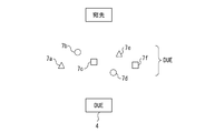
- FIG. 1 shows an example of a wireless communication system according to an embodiment of the present invention.
- the wireless communication system includes a plurality of terminal apparatuses (DUE: Device to Device User Equipment) 1 to 5 and a base station 6.
- DUE Device to Device User Equipment
- the base station 6 is an eNB (evolved (Node B) in this embodiment.
- eNB is a base station used in LTE. Therefore, the base station 6 manages and controls LTE cellular communication. That is, the base station 6 can receive and process cellular communication data signals and control signals transmitted from the terminal device. Moreover, the base station 6 can transmit the data signal and control signal of cellular communication to a terminal device.
- the base station 6 periodically transmits a notification signal.
- the broadcast signal is received by all the terminal devices in the cell.
- each of the terminal devices 1 to 3, 5 receives a notification signal.
- the terminal device that has received the broadcast signal can determine that it is within the cell of the base station 6.
- the terminal device that has received the broadcast signal may transmit a response signal to the base station 6.
- the base station 6 can manage terminal devices located in the cell.
- Terminal devices 1 to 5 support cellular communication and D2D communication, respectively. That is, each of the terminal devices 1 to 5 can transmit data to other terminal devices via the base station 1 and can receive data from other terminal devices via the base station 1. Also, the terminal devices 1 to 5 can communicate directly with other terminal devices via the D2D link without going through the base station 1, respectively.
- Data transmitted by cellular communication or D2D communication is not particularly limited, and includes audio data, image data, moving image data, text data, and the like.
- a terminal device that supports D2D communication may be referred to as “DUE”.
- Each terminal device broadcasts a discovery signal of D2D communication periodically, for example.
- the discovery signal is used to notify the other terminal devices of the presence of the terminal device that generated the discovery signal. Therefore, the discovery signal transmits a message including identification information of the transmission source terminal device of the discovery signal.
- the discovery signal transmitted from the DUE 4 transmits a message including “source ID: DUE 4”.
- the discovery sequence is based on PRACH (Physical Random Access Channel), SRS (Sounding Reference Signal), and / or PSS (Primary Synchronization Signal) / SSS (Secondary Synchronization Signal), for example.
- the discovery signal message is transmitted using, for example, PUSCH (Physical-Uplink-Shared-Channel).
- the discovery signal transmitted from DUE 4 is received by a terminal device located in the vicinity of DUE 4.
- DUE 1 to 3 each receive a discovery signal transmitted from DUE 4.
- the DUE 4 can receive the discovery signals transmitted from the DUEs 1 to 3, respectively.
- the DUE 4 when the DUE 4 performs cellular communication, for example, a cell search is performed to detect a base station. However, in the example shown in FIG. 1, the DUE 4 cannot detect the base station because it is not located in the cell of the base station 6. In this case, the DUE 4 accesses the base station 6 using D2D communication according to the following procedure.
- the DUE4 broadcasts a relay station discovery signal with a predetermined transmission power.
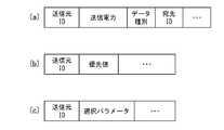
- the transmission power information is included in the discovery message as shown in the example of FIG. 2A
- the transmission power of the relay station discovery signal may be different for each terminal device.
- the relay station discovery signal transmits a message including identification information of the transmission source terminal device of the relay station discovery signal in the same manner as a normal discovery signal.
- the discovery message transmitted by the relay station discovery signal includes, for example, a transmission source ID, transmission power information, and data type information as shown in FIG.
- the transmission source ID identifies the transmission source of the relay station discovery signal.
- the transmission power information represents the transmission power of the relay station discovery signal.
- the data type information represents the type of data to be transmitted by D2D communication after the D2D link is established.
- the data type may represent emergency communication or non-emergency communication.
- Emergency communications include, for example, calls that call the police or fire department.
- the data type is specified by the user of the terminal device.
- the discovery message may include a destination ID. The destination ID identifies the device that is the destination of the data.
- the relay station discovery signal transmitted from DUE 4 is received by DUE 1 to 3. Then, each of the DUEs 1 to 3 calculates a priority value.
- the priority value which will be described in detail later, represents a priority for operating as a relay station. Note that the DUEs 1 to 3 may calculate the priority value only when the data type information included in the received discovery message represents a type specified in advance (for example, emergency communication).
- DUE 1 to 3 each transmit the calculated priority value to DUE 4. At this time, the DUEs 1 to 3 transmit the calculated priority values to the DUE 4 using the response message shown in FIG.
- the terminal apparatus (DUE 1 to 3 in FIG. 1) that has received the relay station discovery signal transmits the priority value to DUE 4 only when the calculated priority value is higher than a pre-specified threshold value. According to this method, by setting the threshold appropriately, only a preferred number of terminal devices transmit the priority value.
- DUE 4 determines a relay station DUE that operates as a relay station based on priority values received from one or a plurality of terminal devices. At this time, the DUE 4 selects the terminal device that has generated the highest priority value as the relay station DUE. In the example shown in FIG. 1, DUE1 is selected from DUE1 to DUE3. In this case, a D2D link is established between DUE4 and DUE1. Further, the DUE 1 is set so as to transfer data received from the DUE 4 via the D2D link to the base station 6. That is, D2D communication is performed between DUE4 and DUE1, and cellular communication is performed between DUE1 and base station 6.
- the priority value is calculated based on at least one of the following parameters.
- RSRP Reference Signal Received Power
- Destination side RSRP (3) Battery level (4) Number of adjacent DUEs (5) Interference
- the RSRP on the transmission side represents the received power of the signal transmitted from the transmission source of the relay station discovery signal.
- the transmission power of the relay station discovery signal is determined in advance as described above.
- the transmission power of the relay station discovery signal is notified using the relay station discovery signal as shown in FIG. Therefore, the relay station discovery signal is used as a reference signal in RSRP measurement.
- DUE 1 to 3 each measure the reception power of the relay station discovery signal transmitted from DUE 4.
- the RSRP on the destination side represents the received power of the signal transmitted from the destination device.
- “Destination” is, for example, the base station 6.
- each terminal apparatus measures the reception power of the broadcast signal transmitted from the base station 6, for example.
- the notification signal is used as a reference signal in the RSRP measurement.
- each of DUE 1 to 3 measures the reception power of a broadcast signal transmitted from base station 6.
- the remaining battery capacity represents the remaining battery capacity built into the terminal device.
- each of the DUEs 1 to 3 monitors the remaining battery level of its own device.
- the number of adjacent DUEs represents the number of DUEs that can be accessed with one hop.
- each DUE can detect an adjacent DUE.
- the number of discovery signal transmission sources detected corresponds to the number of adjacent DUEs.
- DUE1 to DUE4 broadcast discovery signals.
- DUE1 receives discovery signals from DUE2 to DUE4, respectively.
- the “number of adjacent DUEs” of DUE1 is 3. Since the DUE is a wireless communication node that supports D2D communication, the “number of adjacent DUEs” may be referred to as “the number of adjacent D2D nodes”.
- the interference is not particularly limited, but in this example, the interference is calculated based on the received power of the target signal and the predicted interference power (or based on the ratio of the received power of the target signal to the predicted interference power).
- DUE 1 receives a target signal from DUE 4.
- DUE1 calculates a path loss PL (4,1) between DUE4 and DUE1 by the following equation.
- PL (4,1) P0-Pr (d)
- P0 represents the transmission power of the relay station discovery signal.
- the transmission power of the relay station discovery signal is notified by a relay station discovery message as shown in FIG. Pr (d) is the received power of the relay station discovery signal in DUE1.
- the DUE 1 has previously measured the path loss with the adjacent DUE.
- the DUE 1 has previously measured the path loss PL (2, 1) between the DUE 2 and the DUE 1 and the path loss PL (3, 1) between the DUE 3 and the DUE 1.
- each DUE shall be able to measure or estimate the path loss between adjacent DUEs using the discovery signal broadcast regularly, for example.
- the path loss PL (4, 1) when the path loss PL (4, 1) is small, the received power of the target signal is large in the DUE 1. In this case, interference with the target signal tends to be small.
- the path loss PL (4,1) is large, the received power of the target signal is small in DUE1. In this case, interference with the target signal tends to increase.
- the path loss (PL (2,1), PL (3,1)) between adjacent DUEs the predicted interference power is large in DUE1. In this case, interference with the target signal tends to increase.
- the path loss between adjacent DUEs is large, the predicted interference power is small in DUE1. In this case, interference with the target signal tends to be small.
- DUE1 can calculate interference based on the ratio of the path loss PL between DUE4 and DUE1 and the path loss between adjacent DUEs, for example. At this time, interference may be calculated based on the ratio of the path loss PL between DUE 4 and DUE 1 and the minimum value of the path loss between each adjacent DUE.
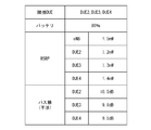
- Each DUE may be provided with a parameter table for storing the above parameters.
- An example of the parameter table is shown in FIG. FIG. 3 shows an example of a parameter table provided in the DUE 1.
- DUE2, DUE3, and DUE4 are detected as adjacent DUEs.
- the number of adjacent DUEs is 3 in this example.
- the transmission source of the relay station discovery signal (DUE4) may be excluded from the detected DUEs (DUE2 to DUE4).
- the path loss is used to calculate interference as described above.
- the parameter table is periodically updated, for example.
- the terminal device when receiving the relay station discovery signal, calculates a priority value.
- the priority value is calculated by the following formula, for example.
- Priority value w1 * RSRP (S) + w2 * RSRP (D) + w3 * BTT-w4 * NUM_DUE-w5 * INTER w1 to w5 each represent a weight. w1 to w5 are zero or positive values.
- RSRP (S) represents the received power of the reference signal received from the transmission source terminal device.
- RSRP (D) represents the received power of the reference signal received from the destination device.
- BTT represents the remaining battery level.
- NUM_DUE represents the number of adjacent DUEs.
- INTER represents interference.
- the weights w1 to w5 are determined based on the network policy. For example, when communication quality is regarded as important, w1, w2, and w5 are increased. Further, w4 may be increased in order to reduce the concentration of the load on a specific terminal device.
- Priority value is calculated based on at least one of the parameters described above. Therefore, for example, when calculating the priority value based only on RSRP, w1 to w2 are each 1, and w3 to w5 are each zero.
- Each terminal device that has received the relay station discovery signal compares the calculated priority value with a predetermined threshold value. When the priority value is higher than the threshold value, the terminal device notifies the transmission source terminal device of the priority value.
- the transmission source terminal apparatus determines a relay station DUE that operates as a relay station based on a priority value received from one or a plurality of terminal apparatuses. At this time, the DUE 4 selects the terminal device that has generated the highest priority value as the relay station DUE that operates as the relay station.
- the threshold value is determined based on, for example, simulation or measurement in advance.
- the threshold is used to determine whether the DUE can operate as a relay station. For example, when the threshold is high, only the DUE that can provide high performance as a relay station transmits the priority value to the transmission source terminal device. In this case, a DUE that operates as a relay station is selected from one or a plurality of DUEs that can provide high performance as the relay station. Therefore, communication with good quality is provided. However, if the threshold is too high, there is a possibility that a candidate for DUE that operates as a relay station cannot be found. On the other hand, if the threshold is too low, the priority value may be notified from a large number of DUEs to the source terminal device. In this case, D2D communication may be congested by the procedure for transmitting the priority value. Therefore, the threshold is determined so that the number of priority values received by the transmission source terminal device approaches a predetermined number (for example, 5).
- a predetermined number for example, 5
- the threshold may be increased in an area where the density where DUE exists is high compared to an area where the density where DUE exists.
- a threshold may be dynamically set from the base station to each DUE.
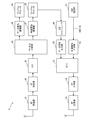
- FIG. 4 shows an example of a terminal device.
- the terminal device 10 corresponds to the DUEs 1 to 4 in the example shown in FIG. Moreover, the terminal device 10 supports cellular communication and D2D communication. The terminal device 10 may have other functions not shown in FIG.
- the terminal device 10 includes a traffic processing unit 11, a channel encoder 12, an IFFT circuit 13, a CP adding unit 14, an RF transmitter 15, an RF receiver 16, and channel demodulation in order to support cellular communication. And a RSRP calculator 18.
- the traffic processing unit 11 generates traffic to be transmitted by cellular communication.
- the channel encoder 12 encodes the traffic output from the traffic processing unit 11.
- the IFFT circuit 13 performs inverse fast Fourier transform on the output signal of the channel encoder 12 to generate a time domain signal.
- the CP adding unit 14 adds a cyclic prefix (CP: Cyclic Prefix) to the time domain signal output from the IFFT circuit 13. Then, the RF transmitter 15 transmits a cellular signal via the antenna. The cellular signal is received by the base station.
- CP Cyclic Prefix
- the RF receiver 16 receives a cellular signal transmitted from the base station.
- the channel demodulator 17 demodulates the received cellular signal.
- the channel demodulator 17 extracts the D2D resource allocation instruction from the received cellular signal and passes it to the D2D scheduler 21 described later.
- the RSRP calculator 18 calculates received power of a reference signal (for example, a broadcast signal) transmitted from the base station. The received power obtained by the RSRP calculator 18 may be used as the destination RSRP when calculating the priority value.
- the terminal device 10 includes a D2D scheduler 21, a D2D data generator 22, a discovery signal generator 23, an RF transmitter 24, an RF receiver 25, a data signal demodulator 26, and a discovery signal detector 27.
- the D2D scheduler 21 can determine a resource to be used for D2D communication from resources provided by the wireless communication system or resources prepared in advance. For example, when the frequency used for D2D communication is determined by the D2D scheduler 21, the terminal device 10 performs D2D communication at the frequency. Further, the D2D scheduler 21 can also control the D2D communication of the terminal device 10 based on the resource allocation instruction received from the base station. For example, when the frequency of D2D communication is designated by the resource allocation instruction, the D2D scheduler 21 controls the D2D data generator 22 and / or the RF transmitter 24 so that the D2D signal is transmitted at the designated frequency. To do. In addition, the D2D scheduler 21 may control the RF receiver 25 and / or the data signal demodulator 26 to receive a D2D signal at a specified frequency.
- the D2D data generator 22 generates transmission data for D2D communication according to control by the D2D scheduler 21.
- the D2D data generator 22 can also generate a response message including the priority value obtained by the priority value calculator 30.
- the discovery signal generator 23 generates a discovery signal / relay station discovery signal.
- the discovery signal / relay station discovery signal carries identification information of the own device.
- the discovery signal / relay station discovery signal is transmitted using, for example, PUSCH.
- the RF transmitter 24 transmits a D2D signal (including a D2D data signal, a discovery signal, and a relay station discovery signal) via an antenna.
- the RF receiver 25 receives a D2D signal (including a D2D data signal, a discovery signal, and a relay station discovery signal) transmitted from another terminal device.
- the data signal demodulator 26 demodulates the received D2D data signal to reproduce D2D data.
- Discovery signal detector 27 detects a discovery signal / relay station discovery signal from a D2D signal transmitted from another terminal device. At this time, the discovery signal detector 27 acquires the identification information of the terminal device that is the transmission source of the discovery signal / relay station discovery signal. Further, the discovery signal detector 27 can extract transmission power information and data type information from the relay station discovery signal.
- the RSRP calculator 28 calculates received power of a reference signal (for example, discovery signal / relay station discovery signal) transmitted from another terminal device. Note that the received power obtained by the RSRP calculator 28 may be used to calculate a priority value.
- the interference calculator 29 calculates the interference that the target signal may receive based on the reception power of the discovery signal / relay station discovery signal. As described above, this interference is calculated based on the path loss between the terminal devices.
- the priority value calculator 30 calculates a priority value using at least one of the parameters (1) to (5) described above when the terminal device 10 receives the relay station discovery signal.
- the RSRP is calculated by the RSRP calculators 18 and 28.
- the remaining battery level is obtained by monitoring a battery (not shown).
- the number of adjacent DUEs can be obtained by counting the terminal devices from which discovery signals are detected by the discovery signal detector 27.
- the interference is calculated by the interference calculator 29.
- the threshold determination unit 31 determines whether or not to transmit the priority value calculated by the priority value calculator 30 to the transmission source terminal device. That is, when the calculated priority value is higher than the threshold value, the threshold value determination unit 31 determines to transmit the priority value to the transmission source terminal device, and when the calculated priority value is equal to or less than the threshold value, the priority value is determined. It is determined that the value is not transmitted to the transmission source terminal device. When it is determined that the priority value is transmitted to the transmission source terminal device, the priority value calculated by the priority value calculator 30 is transmitted to the transmission source terminal using the D2D data generator 22.
- the selection unit 32 selects a DUE that operates as a relay station (hereinafter, relay station DUE) based on the priority value received from one or more other terminal devices. For example, the DUE that generated the highest priority value is selected as the relay station DUE.
- the terminal device 10 has a function of establishing a D2D link with the relay station DUE.
- the communication circuit is set so as to transfer data received from the terminal device 10 via the D2D link to the destination device (base station 6 in the example shown in FIG. 1).
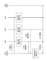
- FIG. 5 shows an example of the hardware configuration of the terminal device.
- the terminal device 10 includes a processor 10a, a memory 10b, a transmission / reception circuit 10c, and a battery 10d. Note that the terminal device 10 may have other hardware elements.
- the processor 10a realizes the function of the terminal device 10 by executing a given program.
- the functions of the signal demodulator 26, discovery signal detector 27, RSRP calculator 28, interference calculator 29, priority value calculator 30, threshold value determination unit 31, and selection unit 32 can be realized by the processor 10a.
- the memory 10b stores a program executed by the processor 10a.
- the memory 10b stores a parameter table shown in FIG.
- the memory 10b includes a work area for the processor 10a.
- the transmission / reception circuit 10c corresponds to the RF transmitter 15, the RF receiver 16, the RF transmitter 24, and the RF receiver 25 shown in FIG.
- the battery 10d supplies power to the processor 10a, the memory 10b, and the transmission / reception circuit 10c. The remaining amount of the battery 10d is periodically monitored by the processor 10a (priority value calculator 30).
- FIG. 6 is a diagram illustrating an example of a base station.
- the base station 6 includes an RF receiver 41, a CP removing unit 42, an FFT circuit 43, a channel separator 44, a data signal demodulator 45, a channel decoder 46, a control signal demodulator 47, and a channel decoder 48.
- D2D resource scheduler 49 data signal generator 50, DUE selection unit 51, control signal generator 52, IFFT circuit 53, CP addition unit 54, and RF transmitter 55.
- the base station 6 may have other functions.
- the RF receiver 41 receives a cellular signal transmitted from the terminal device 10.
- the CP removal unit 42 removes the cyclic prefix from the received cellular signal.
- the FFT circuit 43 performs a fast Fourier transform on the received signal to generate a frequency domain signal.
- the channel separator 44 separates the received signal into a data signal and a control signal in the frequency domain.
- the data signal demodulator 45 demodulates the received data signal and reproduces the data.
- the channel decoder 46 decodes the reproduction data.
- the control signal demodulator 47 demodulates the received control signal.
- the channel decoder 48 reproduces control information by decoding the demodulated control signal.
- the D2D scheduler 49 uses the control information reproduced by the channel decoder 48 to generate a resource allocation instruction for D2D communication.
- the data signal generator 50 generates a data signal to be transmitted to the terminal device 10.
- the DUE selection unit 51 designates one or a plurality of terminal device candidates that operate as a relay station from terminal devices located in the cell. And the DUE selection part 51 outputs the identification information which identifies the designated terminal device.
- the control signal generator 52 generates a control signal for controlling the terminal device 10. Note that the resource allocation instruction generated by the D2D scheduler 49 is transmitted to the terminal device 10 by the data signal generator 50 or the control signal generator 52. Also, identification information representing the terminal device selected by the DUE selection unit 51 is transmitted to the terminal device 10 by the control signal generator 52.
- the IFFT circuit 53 performs inverse fast Fourier transform on the control signal and the data signal to generate a time domain signal.
- the CP adding unit 54 adds a cyclic prefix to the time domain signal output from the IFFT circuit 53. Then, the RF transmitter 55 transmits a cellular signal through the antenna.
- FIG. 7 shows an example of a sequence for selecting a relay station in the first embodiment.
- the DUE 4 accesses the base station 6. That is, DUE 4 is a transmission source terminal device, and base station 6 is a destination device.
- the DUE 4 is located outside the cell of the base station 6 and cannot directly access the base station 6. That is, the DUE 4 cannot detect the base station 6 when executing the cell search. Therefore, the DUE 4 selects a DUE that operates as a relay station between the DUE 4 and the base station 6.
- DUE4 broadcasts a relay station discovery signal.
- This relay station discovery signal transmits a discovery message including “transmission source ID: DUE4”, “transmission power”, and “data type: emergency”.
- the relay station discovery signals are received by the DUEs 1 to 3, respectively.
- the relay station discovery signal may include a destination ID that designates “base station” to indicate that the relay is UE-to-Network relay.
- the relay station discovery signal does not include a destination ID, each DUE can understand that the relay station discovery signal requests relay of UE-to-Network as a default. In these cases, each DUE that has received the relay station discovery recognizes the nearest base station as the destination.
- the DUE 1 to 3 When each of the DUEs 1 to 3 detects that the data type notified by the discovery message is “emergency”, the DUE 1 to 3 starts processing for calculating a priority value.
- the priority value is calculated using at least one of the transmission source side RSRP, the destination side RSRP, the remaining battery level, the number of adjacent DUEs, and interference.
- the priority value is preferably calculated using at least the source-side RSRP and the destination-side RSRP.
- Each DUE 1 to 3 compares the calculated priority value with a predetermined threshold value. When the calculated priority value is higher than the threshold value, the DUE transmits the priority value to the DUE 4. In the example illustrated in FIG. 7, the priority value is higher than the threshold value in DUE 1 and 2, and the priority value is lower than the threshold value in DUE 3. Therefore, each of DUE 1 and 2 transmits the priority value calculated by its own device to DUE 4. That is, priority value 1 is notified from DUE1 to DUE4, and priority value 2 is notified from DUE2 to DUE4.
- DUE 4 selects a DUE that operates as a relay station based on priority values received from one or a plurality of DUEs.
- DUE 4 receives priority value 1 from DUE 1 and receives priority value 2 from DUE 2.
- the priority value 1 is higher than the priority value 2.
- the DUE 4 selects DUE 1 as the relay station DUE.
- DUE4 establishes a D2D link with DUE1.
- the communication circuit is set so that DUE1 transfers data received from DUE4 via the D2D link to base station 6.
- data transmitted from the DUE 4 to the base station 6 is relayed by the DUE 1 and transmitted to the base station 6.
- D2D communication is performed between the DUE 4 and the DUE 1 via the D2D link, and cellular communication is performed between the DUE 1 and the base station 6.
- a relay station DUE that operates as a relay station is selected from among a plurality of DUEs.
- the relay station DUE is selected in consideration of the communication environment and the operating state of each DUE, the quality of communication between the terminal device and the destination device is good.
- the relay station DUE is selected based on the priority value generated in each DUE. At this time, only a priority value higher than a predetermined threshold is transmitted from the DUE to the terminal device. Therefore, traffic for notification of priority values is suppressed.
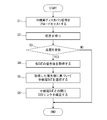
- FIG. 8 is a flowchart showing processing of a terminal device that selects a relay station.
- the process of this flowchart is executed in the DUE 4 shown in FIG. 1 or FIG. 7, for example. Moreover, the process of this flowchart is performed by the processor 10a of the terminal device which selects a relay station. Furthermore, the processing of this flowchart is executed when, for example, the terminal device cannot detect the base station in the cell search.
- the terminal device broadcasts a relay station discovery signal.
- the terminal device waits for a response message corresponding to the relay station discovery signal.
- the processing of the terminal device proceeds to S4.
- the terminal device cannot receive the response message within a predetermined time from when the relay station discovery signal is transmitted, it is determined that the terminal device is isolated. In this case, the processing of the terminal device ends.
- the terminal device acquires a priority value from the received response message. That is, the terminal device acquires the priority value generated in each DUE.
- the terminal device selects the relay station DUE based on the acquired priority value. Then, the terminal device transmits a message instructing the relay station DUE to operate as a relay station, and establishes a D2D link with the relay station DUE.
- FIG. 9 is a flowchart showing processing of a DUE that can be selected as a relay station.
- the processing in this flowchart is executed by, for example, the DUEs 1 to 3 shown in FIG. 1 or FIG.
- the processing of this flowchart is executed by the processor 10a of the DUE.
- the DUE receives the relay station discovery signal from the transmission source terminal device.
- the DUE refers to the data type in the discovery message and determines whether to respond to the relay station discovery signal. For example, if the data type is “emergency”, the DUE determines to respond to the relay station discovery signal.
- the DUE calculates the reception power of the relay station discovery signal. This received power is stored in the parameter table as the source RSRP.
- the DUE acquires other selection parameters (destination side RSRP, remaining battery level, number of adjacent DUEs, interference, etc.). For example, the selection parameter is measured in advance and stored in the parameter table shown in FIG. However, the DUE may measure each selection parameter when receiving the relay station discovery signal.
- the DUE calculates a priority value based on the selection parameters (including the transmission side RSRP).
- the DUE compares the priority value obtained in S15 with a threshold value. When the priority value is higher than the threshold value, the DUE generates a response message including the priority value and transmits it to the transmission source terminal apparatus in S17. On the other hand, if the priority value is equal to or less than the threshold value, the DUE does not respond to the relay station discovery signal.
- the destination device is a base station device, but the present invention is not limited to this form. That is, the destination device may be a terminal device (here, DUE).
- DUE terminal device
- DUE 4 wants to access DUE 5, but a radio signal transmitted from DUE 4 does not reach DUE 5.
- the DUE that operates as the relay station is selected from the DUEs 1 to 3.
- the transmission source terminal device may broadcast a discovery message including the destination ID using a relay station discovery signal.
- the DUE that has received the relay station discovery signal can identify the destination device, and thus can acquire the destination-side RSRP and the like. That is, the DUE that has received the relay station discovery signal can calculate the priority value in the same manner as when the destination is the base station. Therefore, according to the first embodiment, even if the destination device is a DUE, a DUE that preferably operates as a relay station is selected, and a relay operation is provided by the selected DUE.
- Terminal devices that can operate as relay stations may be grouped.
- DUEs 7a and 7e belong to the first group
- DUEs 7b and 7d belong to the second group
- DUEs 7c and 7f belong to the third group.
- the DUEs 7a and 7e belonging to the first group calculate the priority value only when receiving the relay station discovery signal designating the data type (for example, report to the police) corresponding to the first group, To DUE4).
- the DUEs 7b and 7d belonging to the second group calculate the priority value and receive the relay station discovery signal that specifies the data type (for example, notification to the fire department) corresponding to the second group, and the transmission source terminal Transmit to the device (DUE4).
- the threshold for determining whether or not to transmit the priority value may be different for each group.
- the transmission source terminal apparatus selects the relay station DUE based on the priority value calculated by each DUE, but the present invention is not limited to this method.
- the base station may select the relay station DUE based on the priority value calculated in each DUE.
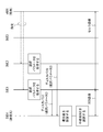
- FIG. 11 shows an example of a sequence in which the base station selects a relay station. Note that the procedure for broadcasting the relay station discovery signal by the transmission source terminal device and the procedure for calculating the priority value by the DUE that has received the relay station discovery signal are substantially the same in FIGS.
- DUE1 and DUE2 transmit priority value 1 and priority value 2 to the base station 6, respectively.
- the base station 6 selects a DUE that operates as a relay station based on the received priority value.
- DUE1 is selected as the relay station DUE.
- the base station 6 transmits a message indicating that DUE1 is selected as the relay station DUE to the DUE1, and the DUE1 transfers this message to the transmission source terminal device (here, DUE4).
- the DUE 1 relays communication between the DUE 4 and the base station 6.
- the source terminal device broadcasts a relay station discovery signal to start a procedure for selecting a DUE that operates as a relay station.
- a DUE that wishes to operate as a relay station broadcasts a source discovery signal. Whether or not it wishes to operate as a relay station is specified by the user of the DUE, for example. Further, the DUE designated by the base station may broadcast the transmission source discovery signal.
- the source discovery signal is broadcast periodically, for example.
- the transmission source discovery signal includes “transmission source ID” and “selection parameter” as shown in FIG.
- the transmission source ID identifies the transmission source of the transmission source discovery signal.
- the selection parameters include the destination RSRP, the remaining battery level, and the number of adjacent DUEs.
- the destination device is the base station 6 shown in FIG.
- the destination-side RSRP represents the received power of a reference signal (for example, a broadcast signal) transmitted from the base station 6.
- the remaining battery level and the number of adjacent DUEs are the same in the first embodiment and the second embodiment.
- the transmission power of the source discovery signal is preferably determined in advance.
- the transmission power of the source discovery signal may be the same as the normal discovery signal or the relay station discovery signal described above.
- the transmission source terminal device performs cell search when communicating with other terminal devices via the base station 6.
- the transmission source terminal apparatus selects a DUE that operates as a relay station using a transmission source discovery signal received from one or a plurality of DUEs.
- the transmission source terminal apparatus calculates a corresponding priority value based on the reception power of the transmission source discovery signal and the selection parameter transmitted by the transmission source discovery signal.
- a transmission source terminal device selects DUE which operate
- FIG. 12 shows an example of a sequence for selecting a relay station in the second embodiment.
- the DUE 4 accesses the base station 6 as in the sequence shown in FIG. That is, DUE 4 is a transmission source terminal device, and base station 6 is a destination device. Further, it is assumed that the DUE 4 cannot detect the base station 6 when executing the cell search.
- the DUEs 1 to 2 periodically broadcast source discovery signals. That is, DUE 1 and 2 are set in a state where they can be selected as relay stations by the user. Alternatively, the DUEs 1 and 2 are designated by the base station 6 as DUEs that can be selected as relay stations.
- the transmission source discovery signal transmits a discovery message including a selection parameter, as shown in FIG.
- the selection parameters include the destination RSRP, the remaining battery level, and the number of adjacent DUEs.
- the selection parameters collected by the DUE 1 include the reception power of the notification signal transmitted from the base station 6, the remaining battery level of the DUE 1, and the number of D2D nodes adjacent to the DUE 1. Note that the selection parameters of each DUE are stored in the parameter table shown in FIG. 3 as described above.
- DUE 4 waits for a source discovery signal broadcast by another DUE.
- the DUE 4 receives the transmission source discovery signal 1 including the selection parameter 1 from the DUE 1, and receives the transmission source discovery signal 1 including the selection parameter 2 from the DUE 2. Then, DUE 4 calculates a priority value for each of DUE 1 and DUE 2.
- the DUE 4 calculates the reception power of the transmission source discovery signal 1 transmitted from the DUE 1.
- the loss of the path from DUE1 to DUE4 and the loss of the path from DUE4 to DUE1 are substantially the same. Therefore, the reception power of the transmission source discovery signal 1 in the DUE 4 corresponds to the RSRP in the DUE 1 when the reference signal is transmitted from the DUE 4 to the DUE 1. That is, the reception power of the transmission source discovery signal 1 in the DUE 4 corresponds to the transmission side RSRP in the DUE 1 when data is transferred from the DUE 4 to the base station 6 via the DUE 1.
- the DUE 4 uses the reception power of the source discovery signal 1 transmitted from the DUE 1 (that is, the source side RSRP), the destination side RSRP included in the selection parameter 1 received from the DUE 1, the remaining battery level, and the number of adjacent DUEs.
- the priority value of DUE1 is calculated.
- DUE4 calculates the priority value of DUE2 using the reception power of transmission source discovery signal 2 transmitted from DUE2 and selection parameter 2.
- a method for selecting a DUE that operates as a relay station based on a priority value and a method for establishing a link using the selected DUE are substantially the same in the first and second embodiments. Therefore, similarly to the example shown in FIG. 7, the D2D link is established between DUE4 and DUE1 in the sequence shown in FIG. Further, the communication circuit is set so that DUE1 transfers data received from DUE4 via the D2D link to base station 6. As a result, data transmitted from the DUE 4 to the base station 6 is relayed by the DUE 1 and transmitted to the base station 6.
Abstract
L'invention concerne un système de communication sans fil ayant un dispositif de destination, un dispositif de source de transmission pour transmettre des données au dispositif de destination et prendre en charge une communication de dispositif à dispositif (D2D), et une pluralité de dispositifs de terminal prenant en charge la communication D2D. Le dispositif de source de transmission émet un signal de découverte à la pluralité de dispositifs de terminal. Chacun de la pluralité de dispositifs de terminal calcule une valeur de priorité sur la base d'au moins un parmi la puissance électrique reçue du signal de découverte émis par le dispositif de source de transmission, la puissance électrique reçue d'un signal de référence émis par le dispositif de destination, la capacité de batterie restante du dispositif hôte, le nombre de nœuds D2D adjacents au dispositif hôte, et l'interférence reçue en provenance des nœuds D2D adjacents au dispositif hôte. Chacun de la pluralité de dispositifs de terminal transmet les valeurs de priorité respectives au dispositif de source de transmission. Le dispositif de source de transmission sélectionne un dispositif de terminal pour relayer des données parmi la pluralité de dispositifs de terminal, sur la base de la valeur de priorité reçue en provenance d'un ou plusieurs dispositifs de terminal.
Priority Applications (6)
| Application Number | Priority Date | Filing Date | Title |
|---|---|---|---|
| EP15891871.4A EP3297331A4 (fr) | 2015-05-14 | 2015-05-14 | Système de communication sans fil |
| JP2017517561A JPWO2016181547A1 (ja) | 2015-05-14 | 2015-05-14 | 無線通信システム |
| PCT/JP2015/063883 WO2016181547A1 (fr) | 2015-05-14 | 2015-05-14 | Système de communication sans fil |
| CN201580079756.2A CN107615823A (zh) | 2015-05-14 | 2015-05-14 | 无线通信系统 |
| KR1020177032470A KR20170137152A (ko) | 2015-05-14 | 2015-05-14 | 무선 통신 시스템 |
| US15/788,265 US20180041889A1 (en) | 2015-05-14 | 2017-10-19 | Wireless communication system |
Applications Claiming Priority (1)
| Application Number | Priority Date | Filing Date | Title |
|---|---|---|---|
| PCT/JP2015/063883 WO2016181547A1 (fr) | 2015-05-14 | 2015-05-14 | Système de communication sans fil |
Related Child Applications (1)
| Application Number | Title | Priority Date | Filing Date |
|---|---|---|---|
| US15/788,265 Continuation US20180041889A1 (en) | 2015-05-14 | 2017-10-19 | Wireless communication system |
Publications (1)
| Publication Number | Publication Date |
|---|---|
| WO2016181547A1 true WO2016181547A1 (fr) | 2016-11-17 |
Family
ID=57247867
Family Applications (1)
| Application Number | Title | Priority Date | Filing Date |
|---|---|---|---|
| PCT/JP2015/063883 WO2016181547A1 (fr) | 2015-05-14 | 2015-05-14 | Système de communication sans fil |
Country Status (6)
| Country | Link |
|---|---|
| US (1) | US20180041889A1 (fr) |
| EP (1) | EP3297331A4 (fr) |
| JP (1) | JPWO2016181547A1 (fr) |
| KR (1) | KR20170137152A (fr) |
| CN (1) | CN107615823A (fr) |
| WO (1) | WO2016181547A1 (fr) |
Cited By (6)
| Publication number | Priority date | Publication date | Assignee | Title |
|---|---|---|---|---|
| JP2018121171A (ja) * | 2017-01-24 | 2018-08-02 | 株式会社Kddi総合研究所 | 制御装置、通信装置、制御方法、及びプログラム |
| WO2018150514A1 (fr) * | 2017-02-16 | 2018-08-23 | 日本電気株式会社 | Terminal de communication dans un réseau ad-hoc sans fil, procédé de communication, et programme de communication |
| WO2018196497A1 (fr) * | 2017-04-28 | 2018-11-01 | 中兴通讯股份有限公司 | Procédé et dispositif de découverte de relais et de retransmission de relais et support de stockage |
| CN110447272A (zh) * | 2017-03-22 | 2019-11-12 | Idac控股公司 | Nr动态tdd系统内的动态干扰管理 |
| CN110786052A (zh) * | 2017-07-10 | 2020-02-11 | 松下电器(美国)知识产权公司 | 功率控制方法和通信装置 |
| JP7308982B2 (ja) | 2019-12-27 | 2023-07-14 | 三菱電機株式会社 | 端末装置、通信方法および通信システム |
Families Citing this family (8)
| Publication number | Priority date | Publication date | Assignee | Title |
|---|---|---|---|---|
| CN108770074B (zh) * | 2014-12-22 | 2022-09-30 | 中兴通讯股份有限公司 | 实现设备直通中继选择的方法、网络控制节点和用户设备 |
| JP6987073B2 (ja) * | 2016-05-11 | 2021-12-22 | オッポ広東移動通信有限公司Guangdong Oppo Mobile Telecommunications Corp., Ltd. | 通信方法、端末装置及びネットワーク装置 |
| EP3459286B1 (fr) * | 2017-01-30 | 2020-05-13 | Telefonaktiebolaget LM Ericsson (publ.) | Extension de service sans fil utilisant d2d et procédé afin de déterminer un trajet de communication et un service d'urgence |
| US10827558B2 (en) * | 2017-06-26 | 2020-11-03 | Qualcomm Incorporated | Techniques and apparatuses for communication relay discovery |
| FR3087610B1 (fr) * | 2018-10-17 | 2022-04-01 | Bull Sas | Echange de donnees dans une infrastructure des objets connectes |
| CN110087294B (zh) * | 2019-06-14 | 2021-08-24 | Oppo广东移动通信有限公司 | 通信控制方法、射频电路及电子设备 |
| US20210337366A1 (en) * | 2020-04-24 | 2021-10-28 | Adept Tech Solutions Inc. | Communication device, system and method |
| KR102578914B1 (ko) * | 2020-12-17 | 2023-09-15 | 인하대학교 산학협력단 | D2d 기반 ptt 서비스에서 통화시간 및 서비스 커버리지를 극대화하기 위한 릴레이 선택 방법 및 장치 |
Citations (2)
| Publication number | Priority date | Publication date | Assignee | Title |
|---|---|---|---|---|
| WO2014068170A1 (fr) * | 2012-11-05 | 2014-05-08 | Nokia Corporation | Procédé et appareil pour une recherche et une communication de dispositif à dispositif, dans une proximité contrôlée par un réseau |
| WO2015046264A1 (fr) * | 2013-09-27 | 2015-04-02 | 京セラ株式会社 | Procédé de commande de communication et terminal utilisateur |
Family Cites Families (7)
| Publication number | Priority date | Publication date | Assignee | Title |
|---|---|---|---|---|
| GB2497741A (en) * | 2011-12-19 | 2013-06-26 | Renesas Mobile Corp | A verification system for use in requesting access to a D2D communication service |
| TWI621371B (zh) * | 2012-08-23 | 2018-04-11 | 內數位專利控股公司 | 執行裝置對裝置發現方法及裝置 |
| US9072000B2 (en) * | 2012-10-19 | 2015-06-30 | Qualcomm Incorporated | Power efficient relay discovery protocol |
| CN103906266A (zh) * | 2012-12-31 | 2014-07-02 | 中兴通讯股份有限公司 | 无线通信方法、用户设备、网络设备及系统 |
| CN104938021B (zh) * | 2013-01-16 | 2019-01-08 | 交互数字专利控股公司 | 发现信号生成和接收 |
| EP2833694A3 (fr) * | 2013-07-29 | 2015-04-01 | HTC Corporation | Procédé de découverte de relais et communication dans un système de communication sans fil |
| US20180192458A1 (en) * | 2015-06-25 | 2018-07-05 | Nec Corporation | Radio terminal, d2d communication control apparatus, base station, preliminary relay radio terminal selection method, non-transitory computer readable medium |
-
2015
- 2015-05-14 CN CN201580079756.2A patent/CN107615823A/zh active Pending
- 2015-05-14 KR KR1020177032470A patent/KR20170137152A/ko not_active Application Discontinuation
- 2015-05-14 WO PCT/JP2015/063883 patent/WO2016181547A1/fr unknown
- 2015-05-14 EP EP15891871.4A patent/EP3297331A4/fr not_active Withdrawn
- 2015-05-14 JP JP2017517561A patent/JPWO2016181547A1/ja active Pending
-
2017
- 2017-10-19 US US15/788,265 patent/US20180041889A1/en not_active Abandoned
Patent Citations (2)
| Publication number | Priority date | Publication date | Assignee | Title |
|---|---|---|---|---|
| WO2014068170A1 (fr) * | 2012-11-05 | 2014-05-08 | Nokia Corporation | Procédé et appareil pour une recherche et une communication de dispositif à dispositif, dans une proximité contrôlée par un réseau |
| WO2015046264A1 (fr) * | 2013-09-27 | 2015-04-02 | 京セラ株式会社 | Procédé de commande de communication et terminal utilisateur |
Non-Patent Citations (5)
| Title |
|---|
| CATT: "Discussion on D2D synchronization sources", 3GPP TSG-RAN WG1#78 R1-142894, 10 August 2014 (2014-08-10), XP050788378 * |
| COOLPAD: "Considerations D2D Synchronization", 3GPP TSG-RAN WG1 #76B R1-141721, 27 March 2014 (2014-03-27), XP050787387 * |
| SAMSUNG: "Issues to support UE2NW relay UE in D2D communication", 3GPP TSG-RAN WG2 #89BIS R2-151290, 10 April 2015 (2015-04-10), XP050936241 * |
| SAMSUNG: "Resource allocation for synchronization signal to assist D2D discovery/communication in asynchronous network", 3GPP TSG- RAN WG1#78 R1-143097, 10 August 2014 (2014-08-10), XP050788575 * |
| See also references of EP3297331A4 * |
Cited By (14)
| Publication number | Priority date | Publication date | Assignee | Title |
|---|---|---|---|---|
| JP2018121171A (ja) * | 2017-01-24 | 2018-08-02 | 株式会社Kddi総合研究所 | 制御装置、通信装置、制御方法、及びプログラム |
| JPWO2018150514A1 (ja) * | 2017-02-16 | 2019-11-14 | 日本電気株式会社 | 無線アドホックネットワークにおける通信端末、通信方法及び通信プログラム |
| WO2018150514A1 (fr) * | 2017-02-16 | 2018-08-23 | 日本電気株式会社 | Terminal de communication dans un réseau ad-hoc sans fil, procédé de communication, et programme de communication |
| US11032749B2 (en) | 2017-02-16 | 2021-06-08 | Nec Corporation | Communication terminal in wireless ad-hoc network, communication method, and communication program |
| US11388681B2 (en) | 2017-03-22 | 2022-07-12 | Idac Holdings, Inc. | Dynamic interference management in NR dynamic TDD systems |
| CN110447272A (zh) * | 2017-03-22 | 2019-11-12 | Idac控股公司 | Nr动态tdd系统内的动态干扰管理 |
| CN110447272B (zh) * | 2017-03-22 | 2023-01-24 | Idac控股公司 | Nr动态tdd系统内的动态干扰管理 |
| WO2018196497A1 (fr) * | 2017-04-28 | 2018-11-01 | 中兴通讯股份有限公司 | Procédé et dispositif de découverte de relais et de retransmission de relais et support de stockage |
| CN110786052A (zh) * | 2017-07-10 | 2020-02-11 | 松下电器(美国)知识产权公司 | 功率控制方法和通信装置 |
| JP2020526949A (ja) * | 2017-07-10 | 2020-08-31 | パナソニック インテレクチュアル プロパティ コーポレーション オブ アメリカPanasonic Intellectual Property Corporation of America | 電力制御方法および通信装置 |
| US11382046B2 (en) | 2017-07-10 | 2022-07-05 | Panasonic Intellectual Property Corporation Of America | Power control method and communication apparatus |
| JP7110239B2 (ja) | 2017-07-10 | 2022-08-01 | パナソニック インテレクチュアル プロパティ コーポレーション オブ アメリカ | 電力制御方法および通信装置 |
| CN110786052B (zh) * | 2017-07-10 | 2022-08-30 | 松下电器(美国)知识产权公司 | 功率控制方法和通信装置 |
| JP7308982B2 (ja) | 2019-12-27 | 2023-07-14 | 三菱電機株式会社 | 端末装置、通信方法および通信システム |
Also Published As
| Publication number | Publication date |
|---|---|
| KR20170137152A (ko) | 2017-12-12 |
| EP3297331A4 (fr) | 2018-04-25 |
| EP3297331A1 (fr) | 2018-03-21 |
| US20180041889A1 (en) | 2018-02-08 |
| CN107615823A (zh) | 2018-01-19 |
| JPWO2016181547A1 (ja) | 2018-02-22 |
Similar Documents
| Publication | Publication Date | Title |
|---|---|---|
| WO2016181547A1 (fr) | Système de communication sans fil | |
| US11026148B2 (en) | Electronic apparatus for wireless communication and wireless communication method | |
| KR101936149B1 (ko) | Wlan 802.11에서의 고속 연관 | |
| US10165496B2 (en) | Terminal device having a relay function and method of providing information related to a relay function | |
| JP6264458B2 (ja) | 無線通信システム | |
| US10440628B2 (en) | D2D information processing method to influence communication service for UEs | |
| TWI631836B (zh) | 使用無線電存取網路來對wi-fi和未授權頻帶進行通道可用性協調 | |
| WO2018105263A1 (fr) | Dispositif terminal, procédé et support d'enregistrement | |
| JP6517921B2 (ja) | ユーザ装置、移動通信システム及び通信制御方法 | |
| US20110105109A1 (en) | Mobile station apparatus, base station apparatus, and mobile communication system | |
| US9544782B2 (en) | Systems, apparatus, and methods for range extension of wireless communication | |
| US9729388B2 (en) | Method and apparatus for wireless link recovery between BSs in a wireless communication system | |
| JP2020517143A (ja) | 周波数選択方法、ランダムアクセス方法および装置 | |
| US20210289401A1 (en) | Electronic device and method executed by electronic device | |
| JP6959990B2 (ja) | 移動通信システム及び装置 | |
| JPWO2014115185A1 (ja) | 無線通信方法、無線通信システム、無線基地局および無線端末 | |
| US20160381694A1 (en) | Wireless communication system, terminal, and processing method | |
| CN106605444B (zh) | 基于代表的网络间通信 | |
| KR20140111872A (ko) | 디바이스 간 직접 통신을 수행하는 시스템에서 스케줄링 방법 및 장치 | |
| KR20120081207A (ko) | 무선 통신 시스템, 고전력 기지국, 저전력 기지국, 무선 단말 및 무선 통신 방법 | |
| KR20230044968A (ko) | 통신 시스템에서 자원 할당 방법 및 장치 | |
| WO2019043799A1 (fr) | Équipement utilisateur, station de base et procédé de communication sans fil | |
| KR20140065356A (ko) | 단말 간 직접 통신을 위한 디스커버리 방법 및 장치 |
Legal Events
| Date | Code | Title | Description |
|---|---|---|---|
| 121 | Ep: the epo has been informed by wipo that ep was designated in this application |
Ref document number: 15891871 Country of ref document: EP Kind code of ref document: A1 |
|
| ENP | Entry into the national phase |
Ref document number: 2017517561 Country of ref document: JP Kind code of ref document: A |
|
| ENP | Entry into the national phase |
Ref document number: 20177032470 Country of ref document: KR Kind code of ref document: A |
|
| NENP | Non-entry into the national phase |
Ref country code: DE |