WO2016178363A1 - 生体信号検出装置 - Google Patents
生体信号検出装置 Download PDFInfo
- Publication number
- WO2016178363A1 WO2016178363A1 PCT/JP2016/062222 JP2016062222W WO2016178363A1 WO 2016178363 A1 WO2016178363 A1 WO 2016178363A1 JP 2016062222 W JP2016062222 W JP 2016062222W WO 2016178363 A1 WO2016178363 A1 WO 2016178363A1
- Authority
- WO
- WIPO (PCT)
- Prior art keywords
- neck
- neckband
- biological signal
- detection device
- signal detection
- Prior art date
- Legal status (The legal status is an assumption and is not a legal conclusion. Google has not performed a legal analysis and makes no representation as to the accuracy of the status listed.)
- Ceased
Links
Images




Classifications
-
- A—HUMAN NECESSITIES
- A61—MEDICAL OR VETERINARY SCIENCE; HYGIENE
- A61B—DIAGNOSIS; SURGERY; IDENTIFICATION
- A61B5/00—Measuring for diagnostic purposes; Identification of persons
- A61B5/24—Detecting, measuring or recording bioelectric or biomagnetic signals of the body or parts thereof
- A61B5/25—Bioelectric electrodes therefor
- A61B5/251—Means for maintaining electrode contact with the body
- A61B5/256—Wearable electrodes, e.g. having straps or bands
-
- A—HUMAN NECESSITIES
- A61—MEDICAL OR VETERINARY SCIENCE; HYGIENE
- A61B—DIAGNOSIS; SURGERY; IDENTIFICATION
- A61B5/00—Measuring for diagnostic purposes; Identification of persons
- A61B5/02—Detecting, measuring or recording for evaluating the cardiovascular system, e.g. pulse, heart rate, blood pressure or blood flow
-
- A—HUMAN NECESSITIES
- A61—MEDICAL OR VETERINARY SCIENCE; HYGIENE
- A61B—DIAGNOSIS; SURGERY; IDENTIFICATION
- A61B5/00—Measuring for diagnostic purposes; Identification of persons
- A61B5/24—Detecting, measuring or recording bioelectric or biomagnetic signals of the body or parts thereof
- A61B5/25—Bioelectric electrodes therefor
- A61B5/263—Bioelectric electrodes therefor characterised by the electrode materials
- A61B5/27—Conductive fabrics or textiles
-
- A—HUMAN NECESSITIES
- A61—MEDICAL OR VETERINARY SCIENCE; HYGIENE
- A61B—DIAGNOSIS; SURGERY; IDENTIFICATION
- A61B5/00—Measuring for diagnostic purposes; Identification of persons
- A61B5/24—Detecting, measuring or recording bioelectric or biomagnetic signals of the body or parts thereof
- A61B5/25—Bioelectric electrodes therefor
- A61B5/279—Bioelectric electrodes therefor specially adapted for particular uses
- A61B5/28—Bioelectric electrodes therefor specially adapted for particular uses for electrocardiography [ECG]
-
- A—HUMAN NECESSITIES
- A61—MEDICAL OR VETERINARY SCIENCE; HYGIENE
- A61B—DIAGNOSIS; SURGERY; IDENTIFICATION
- A61B5/00—Measuring for diagnostic purposes; Identification of persons
- A61B5/24—Detecting, measuring or recording bioelectric or biomagnetic signals of the body or parts thereof
- A61B5/316—Modalities, i.e. specific diagnostic methods
- A61B5/318—Heart-related electrical modalities, e.g. electrocardiography [ECG]
- A61B5/346—Analysis of electrocardiograms
- A61B5/349—Detecting specific parameters of the electrocardiograph cycle
- A61B5/352—Detecting R peaks, e.g. for synchronising diagnostic apparatus; Estimating R-R interval
Definitions
- the present invention relates to a biological signal detection apparatus that detects a biological signal.
- Patent Document 1 discloses an electrocardiogram measuring apparatus capable of measuring an electrocardiogram while performing daily life without taking off clothes.
- This electrocardiogram measuring apparatus includes a flexible band portion, a reference electrode portion provided on the flexible band portion, and a pair of induction electrode portions.
- the flexible band portion has a so-called neck band shape that can surround the neck portion of the measurement subject from the rear side, and is formed of, for example, plastic.
- the flexible band portion can detachably hold the neck portion of the measurement subject by the clamping pressure based on the elastic deformation.
- the wearing state is maintained by supporting the flexible band portion in the vicinity of the base of the neck portion of the person to be measured in addition to the clamping pressure.
- an electrocardiogram signal can be detected from the vicinity of the carotid artery of the neck without restraining the limbs or the like by making the device a neckband type.
- an electrocardiogram signal can be measured without making the person to be measured conscious of wearing the apparatus substantially unconstrained and non-invasively.
- the thickness of the neck (neck) varies greatly between individuals, and when the neck (neck) is tilted or twisted, the shape of the neck (neck) changes greatly. Therefore, in such a case, the contact state of the induction electrode unit or the like becomes unstable (the close contact state changes), and noise may be easily applied or a biological signal may not be acquired. In particular, the effect is significant when the required contact area is large.
- An object of the present invention is to provide a biological signal detection device capable of performing
- a biological signal detection apparatus includes a neckband that can be worn along a circumferential direction of a user's neck, a pair of sensing units that are attached to the neckband and provided with a detector that detects a biological signal.
- the neckband is formed in a substantially C shape, has elasticity, and biases the sensing unit in a direction to sandwich the neck of the user when worn, and each of the pair of sensing units is connected to the neckband. It is characterized in that it is mounted so as to be swingable around the short direction.
- the neckband is formed in a substantially C shape, has elasticity, and biases the sensing unit in the direction of sandwiching the user's neck when worn. Further, each of the pair of sensing units is attached so as to be swingable about the short direction of the neckband (that is, swingable in the circumferential direction of the neck). Even if the distances are different, the sensing unit can be brought into close contact with the user's neck. In addition, for example, the contact surface can be held following a movement in which the neck is twisted. As a result, the contact state between the detector and the neck can be kept good regardless of individual differences such as the thickness of the neck and the movement of the neck.
- each of the pair of sensing units is attached so as to be swingable about the longitudinal direction of the neckband.
- each of the pair of sensing units is attached so as to be swingable about the longitudinal direction of the neckband (that is, swingable in the axial direction of the neck). It is possible to hold the contact surface following the movement.
- a biological signal detection apparatus includes a neckband that can be worn along a circumferential direction of a user's neck, a pair of sensing units that are attached to the neckband and provided with a detector that detects a biological signal.
- the neckband is formed in a substantially C shape, has elasticity, and urges the sensing part in a direction to sandwich the neck of the user when worn, and each of the pair of sensing parts is It is attached so that rocking is possible about the axial direction of a user's neck.
- the neckband is formed in a substantially C shape, has elasticity, and biases the sensing unit in the direction of sandwiching the user's neck when worn. Furthermore, each of the pair of sensing units is attached so as to be swingable about the axial direction of the neck of the user when worn (that is, swingable in the circumferential direction of the neck). Even if the thickness of the neck is different, the sensing unit can be brought into close contact with the user's neck. In addition, for example, the contact surface can be held following a movement in which the neck is twisted. As a result, the contact state between the detector and the neck can be kept good regardless of individual differences such as the thickness of the neck and the movement of the neck.
- each of the pair of sensing units is attached so as to be swingable about the neck front-rear direction perpendicular to the axial direction of the user's neck at the time of wearing.
- each of the pair of sensing units can swing around the neck longitudinal direction perpendicular to the axial direction of the user's neck at the time of wearing (that is, the neck axis Therefore, at the time of wearing, for example, it is possible to hold the contact surface by following a movement such as tilting the neck.
- spherical heads are formed at both ends of the neckband, and a socket for swinging and rotating the spherical heads is formed at each of the pair of sensing units. .
- each of the pair of sensing units is attached to both ends of the neckband by a ball joint constituted by a spherical head and a socket that holds the spherical head in a swingable manner. Therefore, at the time of wearing, the contact surface between the detector and the neck can be held by following the movement of the neck freely.
- the neckband is extendable in the longitudinal direction.
- the neckband is extendable (that is, the length can be adjusted) in the longitudinal direction (that is, the circumferential direction of the neck), the detector and the neck can be adjusted regardless of the thickness of the neck. It becomes possible to keep the contact state better.
- the pair of sensing units are connected to each other by electrical wiring passing through the inside of the neckband.
- the electric wiring passes through the inside of the neckband, for example, it is possible to prevent the occurrence of noise that may occur when the wiring shakes or touches the wiring. Further, when the cable is exposed, measures such as thickening the cable covering are necessary to prevent the cable from being disconnected, but this can be eliminated.
- the detector is formed so as to protrude from the surface around the sensing unit provided with the detector.
- the detector is formed so as to protrude from the surface around the sensing unit in which the detector is disposed, the adhesion between the detector and the neck can be further increased.
- the sensing unit is configured such that a plurality of parts are swingably connected, and each part is configured to be relatively displaceable.
- the sensing unit is configured such that a plurality of parts are swingably connected, and each part is configured to be relatively displaceable. Therefore, according to the thickness and shape of the neck, each of the plurality of parts can be brought into contact with the neck in a wider area.
- the detector is a biological electrode made of a stretchable conductive cloth and acquiring electrocardiogram or myoelectricity.
- a conductive cloth is used for the detector, it is easy to fit the shape of the user's neck and can be brought into stable contact with the neck.
- the conductive cloth is excellent in air permeability and is not easily stuffy, it can make it difficult for the user to feel uncomfortable even if it is worn for a long time.
- a step that is recessed in the thickness direction of the conductive cloth is provided on each surface except the surface that contacts the neck of the sensing unit.
- the biological signal detection device is mounted on the neck of the user.
- the conductive cloth can be more stably brought into contact with the neck, and the conductive cloth can be prevented from being displaced or pulled out.
- a photoelectric pulse wave sensor In the biological signal detection apparatus according to the present invention, a photoelectric pulse wave sensor, a piezoelectric pulse wave sensor, an oxygen saturation sensor, a microphone, a displacement sensor, an acceleration sensor, a sweat sensor, a temperature sensor, or a humidity sensor is preferably used as the detector. Can be used.
- the biological signal detection apparatus preferably further includes a battery housed in the sensing unit and wireless communication means.
- the battery and the wireless communication means are provided, it is not necessary to connect the cable to another device or a power source, and the cable does not get in the way. Therefore, for example, it is possible to detect a biological signal by wearing for a long time including when the user is active.
- the present invention it is possible to maintain a good contact state between the detector and the neck regardless of individual differences such as the thickness of the neck and the movement of the neck.
- FIG. 1 is a perspective view showing an appearance of the biological signal detection apparatus 1 according to the first embodiment.
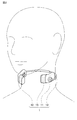
- FIG. 2 is a diagram illustrating a state in which the biological signal detection device 1 is mounted on the neck of a user (subject).
- FIG. 3 is a plan view of the sensing unit 11 constituting the biological signal detection device 1.
- FIG. 4 is an end view of the sensing unit 11 constituting the biological signal detection device 1.
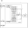
- FIG. 5 is a block diagram showing a functional configuration of the biological signal detection apparatus 1.
- the biological signal detection device 1 is provided with a substantially C-shaped (or U-shaped) neckband 13 that is elastically mounted so as to sandwich the neck from the back side of the user's neck, and is disposed at both ends of the neckband 13.
- a pair of sensing units 11 and 12 that come into contact with both sides of the user's neck are provided.
- Each of the sensing units 11 and 12 is provided with various sensors (detectors) for detecting a biological signal (details will be described later).
- the neckband 13 can be worn along the circumferential direction of the user's neck. That is, as shown in FIG. 2, the neckband 13 is worn along the back of the user's neck from one side of the user's neck to the other side of the neck. More specifically, the neck band 13 includes, for example, a belt-shaped plate spring and a rubber tube that covers the plate spring. Therefore, the neckband 13 is urged so as to shrink inward, and when the user wears the neckband 13, the neckband 13 (sensing units 11 and 12) is in contact with the neck of the user. Retained.
- a rubber tube it is preferable to use what has biocompatibility as a rubber tube. Moreover, it can replace with a rubber tube and can use the tube which consists of a raw material which has elasticity, such as a plastics.
- a cable for electrically connecting both sensing units 11 and 12 is also wired. Here, it is desirable that the cable be coaxial in order to reduce noise.
- each of the pair of sensing parts 11 and 12 is formed with a socket 16b for holding the spherical head 16a so as to be swingable and rotatable. That is, each of the pair of sensing portions 11 and 12 swings at both ends of the neckband 13 by a ball joint 16 having a spherical head portion 16a and a socket 16b that holds the spherical head portion 16a. It is pivotally attached.
- each of the pair of sensing units 11 and 12 can swing about the short direction of the neckband 13 (or the axial direction of the neck of the user wearing the biological signal detection device 1) (that is, the neck of the neck). (Can be swung in the circumferential direction) and at the same time can be swung around the longitudinal direction of the neckband 13 (or the longitudinal direction of the neck perpendicular to the axial direction of the user's neck) (that is, in the axial direction of the neck) Swingable).
- Each of the pair of sensing units 11 and 12 is perpendicular to the short direction of the neckband 13 (or the axial direction of the user's neck) and / or the longitudinal direction (or the axial direction of the user's neck). It is only necessary to be able to oscillate about the neck front-rear direction, and a mechanism for limiting (restricting) rotation about the radial direction of the neck may be provided.
- the neckband 13 has a slide mechanism 13a that can accommodate a part of the neckband 13, for example, so as to cope with a difference in neck thickness (neck circumference) for each user. It is possible to extend and contract (that is, the length can be adjusted).
- the cable described above is preferably passed through the rubber tube of the neckband 13, the spherical head 16a of the neckband 13, and the socket 16b. Further, it is desirable to seal the hole through which the cable is passed with a sealing material or the like for waterproofing.
- the sensing part 11 (12) is mainly composed of a conductive cloth 15 having a stretchable shape formed in a cylindrical shape, a main body part 11a in which a front end side concave part 11b on which the cylindrical conductive cloth 15 is covered, and a front end side concave part. And an input terminal 14 provided in 11b.
- the sensing unit 11 (12) is formed in a lightly curved arc shape so as to easily fit the shape of the neck.
- the sensing unit 11 has a photoelectric pulse wave sensor 20 in addition to the above configuration.
- the conductive cloth 15 is used as an electrode for detecting an electrocardiogram signal.
- the electrocardiogram signal for example, a myoelectric signal or a sweating amount may be detected.
- a piezoelectric pulse wave sensor instead of or in addition to the photoelectric pulse wave sensor 20, a piezoelectric pulse wave sensor, an oxygen saturation sensor, a sound sensor (microphone) for measuring swallowing sounds and voices, a displacement sensor for detecting neck movement, and body movement
- An acceleration sensor that detects body temperature, a temperature sensor that detects body surface temperature, a humidity sensor that detects a sweating state, and the like (corresponding to the detector described in the claims) may be used.
- the photoelectric pulse wave sensor 20 is formed to protrude slightly from the surface around the sensing unit 11 (main body part 11a) where the photoelectric pulse wave sensor 20 is disposed. Yes.
- the conductive cloth 15 is made of conductive yarn having conductivity, and a knitted fabric having elasticity is preferably used.
- the conductive cloth 15 is formed in a cylindrical shape so that the inner diameter when contracted is smaller than the tip-side recess 11b and the inner diameter when extended is greater than the tip-side recess 11b.
- the conductive yarn for example, a resin yarn whose surface is plated with Ag, a carbon nanotube-coated one, or a conductive polymer such as PEDOT may be used.
- PEDOT a conductive polymer which has electroconductivity.
- the conductive cloth 15 is preferably subjected to an end treatment such as folding the edge and sewing with a sewing machine, or a cutting and welding treatment using laser or ultrasonic waves.
- the main body 11a is formed in a substantially quadrangular prism shape (lightly curved quadrangular prism shape) whose corners are rounded (R chamfered) with, for example, resin.
- the tip side recess 11b is also formed in a substantially quadrangular prism shape (lightly curved quadrangular prism shape) with rounded corners (R chamfered).
- the input terminal 14 is provided in the both surfaces or single side
- a step 11c that is recessed in the thickness direction of the conductive cloth 15 is provided on each surface except the surface that contacts the portion. In other words, there is no step (dent) on the surface in contact with the neck, and the step 11c is provided on the other three surfaces.
- the conductive cloth 15 can be set (or replaced) by covering the tip-side recess 11b with the cylindrical conductive cloth 15. At the same time, the conductive cloth 15 and the input terminal 14 are electrically connected. In addition, the conductive cloth 15 is set in the front-end
- a photoelectric pulse wave sensor 20 that has a light emitting element 201 and a light receiving element 202 in the vicinity of the conductive cloth 15 and detects a photoelectric pulse wave signal is disposed on the inner surface of the main body 11a (the surface that contacts the neck). ing.
- the photoelectric pulse wave sensor 20 is a sensor that optically detects a photoelectric pulse wave signal using the light absorption characteristic of blood hemoglobin.
- the light emitting element 201 emits light according to a pulsed drive signal output from a drive unit 350 of the signal processing unit 31 described later.
- a drive unit 350 of the signal processing unit 31 for example, an LED, a VCSEL (Vertical Cavity Surface Emitting LASER), or a resonator type LED can be used.
- the driving unit 350 generates and outputs a pulsed driving signal for driving the light emitting element 201.
- the light receiving element 202 outputs a detection signal corresponding to the intensity of light irradiated from the light emitting element 201 and transmitted through the neck or reflected from the neck.
- a photodiode or a phototransistor is preferably used as the light receiving element 202.
- a photodiode is used as the light receiving element 202.
- the light receiving element 202 is connected to the signal processing unit 31, and a detection signal (photoelectric pulse wave signal) obtained by the light receiving element 202 is output to the signal processing unit 31.
- a battery (not shown) that supplies electric power to the photoelectric pulse wave sensor 20, the signal processing unit 31, the wireless communication module 60, and the like is housed in one sensing unit 11.
- the other sensing unit 12 includes a signal processing unit 31 and a wireless communication module 60 that transmits biological information such as a measured electrocardiogram signal, photoelectric pulse wave signal, and pulse wave propagation time to an external device. (Corresponding to the wireless communication means described in the range).
- Each of the conductive cloths 15 and 15 and the photoelectric pulse wave sensor 20 is connected to the signal processing unit 31, and the detected electrocardiogram signal and photoelectric pulse wave signal are input to the signal processing unit 31.
- the signal processing unit 31 measures the pulse wave propagation time from the time difference between the R wave peak of the detected electrocardiogram signal (cardiac radio wave) and the peak of the first photoelectric pulse wave signal (pulse wave).
- the signal processing unit 31 processes the input electrocardiogram signal and measures a heart rate, a heart beat interval, and the like. Further, the signal processing unit 31 processes the input photoelectric pulse wave signal to measure the pulse rate, the pulse interval, and the like.
- the signal processing unit 31 includes amplification units 311 and 321, a first signal processing unit 310, a second signal processing unit 320, peak detection units 316 and 326, peak correction units 318 and 328, and a pulse wave propagation time measurement unit 330. is doing.
- the first signal processing unit 310 includes an analog filter 312, an A / D converter 313, and a digital filter 314.
- the second signal processing unit 320 includes an analog filter 322, an A / D converter 323, a digital filter 324, and a second-order differentiation processing unit 325.
- the digital filter 314, 324, the second-order differentiation processing unit 325, the peak detection units 316, 326, the peak correction units 318, 328, and the pulse wave propagation time measurement unit 330 are CPUs that perform arithmetic processing.
- a ROM for storing a program and data for causing the CPU to execute each process, a RAM for temporarily storing various data such as calculation results, and the like are included. That is, the functions of the above-described units are realized by executing the program stored in the ROM by the CPU.
- the amplifying unit 311 is configured by an amplifier using, for example, an operational amplifier, and amplifies the electrocardiogram signals detected by the sensing units 11 and 12 (conductive cloths 15 and 15).
- the electrocardiographic signal amplified by the amplifying unit 311 is output to the first signal processing unit 310.
- the amplification unit 321 is configured by an amplifier using an operational amplifier, for example, and amplifies the photoelectric pulse wave signal detected by the photoelectric pulse wave sensor 20.
- the photoelectric pulse wave signal amplified by the amplification unit 321 is output to the second signal processing unit 320.
- the first signal processing unit 310 includes the analog filter 312, the A / D converter 313, and the digital filter 314, and performs filtering processing on the electrocardiogram signal amplified by the amplification unit 311. This extracts the pulsation component.
- the second signal processing unit 320 includes the analog filter 322, the A / D converter 323, the digital filter 324, and the second-order differentiation processing unit 325, and the photoelectric pulse amplified by the amplification unit 321.
- a pulsating component is extracted by applying filtering processing and second-order differentiation processing to the wave signal.
- Analog filters 312, 322 and digital filters 314, 324 remove components (noise) other than the frequency characterizing the electrocardiogram signal and photoelectric pulse wave signal, and perform filtering to improve S / N. More specifically, a frequency component of 0.1 to 200 Hz is generally dominant for an electrocardiogram signal, and a frequency component of 0.1 to several tens of Hz is dominant for a photoelectric pulse wave signal.
- the S / N is improved by performing filtering using the analog filters 312 and 322 and the digital filters 314 and 324 and selectively passing only signals in the frequency range.
- the purpose is to extract only the pulsating component (that is, when it is not necessary to acquire a waveform or the like), a component other than the pulsating component by narrowing the pass frequency range to improve noise resistance. May be blocked.
- the analog filters 312, 322 and the digital filters 314, 324 are not necessarily provided, and only one of the analog filters 312, 322 and the digital filters 314, 324 may be provided. Note that the electrocardiogram signal subjected to the filtering process by the analog filter 312 and the digital filter 314 is output to the peak detection unit 316. Similarly, the photoelectric pulse wave signal subjected to the filtering process by the analog filter 322 and the digital filter 324 is output to the second-order differentiation processing unit 325.
- the second-order differentiation processing unit 325 obtains a second-order differential pulse wave (acceleration pulse wave) signal by second-order differentiation of the photoelectric pulse wave signal.
- the acquired acceleration pulse wave signal is output to the peak detector 326.
- the peak (rising point) of the photoelectric pulse wave is not clearly changed and may be difficult to detect. Therefore, it is preferable to detect the peak by converting it to an acceleration pulse wave.
- a second-order differential processing unit 325 is provided. Is not essential and may be omitted.
- the peak detection unit 316 detects the peak (R wave) of the electrocardiogram signal that has been subjected to signal processing by the first signal processing unit 310 (the pulsating component has been extracted).
- the peak detection unit 326 detects the peak of the photoelectric pulse wave signal (acceleration pulse wave) subjected to the filtering process by the second signal processing unit 320.
- Each of the peak detection unit 316 and the peak detection unit 326 performs peak detection within the normal range of the heartbeat interval and the pulse interval, and information on the peak time, peak amplitude, and the like for all detected peaks is stored in the RAM or the like. save.
- the peak correction unit 318 obtains the delay time of the electrocardiogram signal in the first signal processing unit 310 (analog filter 312 and digital filter 314). The peak correction unit 318 corrects the peak of the electrocardiogram signal detected by the peak detection unit 316 based on the obtained delay time of the electrocardiogram signal. Similarly, the peak correction unit 328 obtains the delay time of the photoelectric pulse wave signal in the second signal processing unit 320 (analog filter 322, digital filter 324, second-order differentiation processing unit 325). The peak correction unit 328 corrects the peak of the photoelectric pulse wave signal (acceleration pulse wave signal) detected by the peak detection unit 326 based on the obtained delay time of the photoelectric pulse wave signal. The corrected peak of the electrocardiogram signal and the corrected peak of the photoelectric pulse wave signal (acceleration pulse wave) are output to the pulse wave propagation time measurement unit 330. Note that providing the peak correction unit 318 is not essential and may be omitted.
- the pulse wave propagation time measurement unit 330 is configured to detect an interval (time difference) between the R wave peak of the electrocardiogram signal corrected by the peak correction unit 318 and the peak of the photoelectric pulse wave signal (acceleration pulse wave) corrected by the peak correction unit 328. ) To determine the pulse wave propagation time.
- the pulse wave propagation time measurement unit 330 calculates, for example, a heart rate, a heartbeat interval, a heartbeat interval change rate, and the like from an electrocardiogram signal in addition to the pulse wave propagation time. Similarly, the pulse wave propagation time measurement unit 330 calculates a pulse rate, a pulse interval, a pulse interval change rate, and the like from the photoelectric pulse wave signal (acceleration pulse wave).
- the acquired measurement data such as pulse wave propagation time, heart rate, and pulse rate is transmitted to, for example, a PC, a portable music player having a display, a smartphone, or the like via the wireless communication module 60.
- the electrocardiogram signal and the photoelectric pulse wave signal are detected by using the electrocardiogram signal measuring apparatus 1 and the pulse wave propagation time is measured, as shown in FIG. And the sensing units 11 and 12 (the conductive cloths 15 and 15 and the photoelectric pulse wave sensor 20) are brought into contact with the neck.
- an electrocardiogram signal between the two sensing units 11 and 12 is detected, and at the same time, a photoelectric pulse wave signal is detected by the photoelectric pulse wave sensor 20. Then, the pulse wave propagation time is acquired from the peak time difference between the electrocardiogram signal and the photoelectric pulse wave signal. Since the method for acquiring the pulse wave propagation time is as described above, detailed description thereof is omitted here.
- the user can detect and measure an electrocardiogram signal, a photoelectric pulse wave signal, a pulse wave propagation time, and the like only by wearing the biological signal detection device 1 on the neck.
- biological information such as the detected and measured electrocardiogram signal, photoelectric pulse wave signal, and pulse wave propagation time is transmitted to an external device by the wireless communication module 60.
- the neckband 13 is formed in a substantially C shape, has elasticity, and biases the sensing units 11 and 12 in the direction of sandwiching the user's neck when worn. Further, since each of the pair of sensing units 11 and 12 is attached to the neckband 13 via the ball joint 16 so as to be swingable and rotatable, it is assumed that, for example, the thickness of the neck is different at the time of wearing. Also, the sensing units 11 and 12 can be brought into close contact with the user's neck. For example, the contact surface can be held following the movement of the neck such as tilting or twisting. As a result, the contact state between the conductive cloth 15 and the photoelectric pulse wave sensor 20 and the neck can be kept good regardless of individual differences such as the thickness of the neck and the movement of the neck.
- the neckband 13 is extendable (that is, the length can be adjusted) in the longitudinal direction (that is, the circumferential direction of the neck), so regardless of the thickness of the neck, The contact state between the conductive cloth 15 and the photoelectric pulse wave sensor 20 and the neck can be kept better.
- the photoelectric pulse wave sensor 20 is formed so as to protrude from the surfaces around the sensing units 11 and 12 in which the photoelectric pulse wave sensor 20 is disposed. Therefore, the adhesiveness between the photoelectric pulse wave sensor 20 and the neck can be further increased.
- the conductive cloth 15 is used as an electrode for detecting an electrocardiogram signal, it is easy to fit the shape of the user's neck, and can be stably brought into contact with the neck. .
- the conductive cloth 15 has excellent breathability and is not easily stuffy, it can make it difficult for the user to feel uncomfortable even if the conductive cloth 15 is worn for a long time.
- the sensing portions 11 and 12 are recessed in the thickness direction of the conductive cloth 15 on each surface (the other three surfaces) excluding the surface in contact with the neck. Since the step 11c is provided, the conductive cloth 15 can be more stably brought into contact with the neck when the biological signal detection device 1 is mounted on the neck of the user, and the conductive cloth It becomes possible to prevent 15 from slipping out or coming off.
- the battery and the wireless communication module 60 are built in the sensing units 11 and 12, there is no need to connect to other devices or power sources with cables, and the cables become an obstacle. There is nothing. Therefore, for example, it is possible to detect a biological signal by wearing for a long time including when the user is active.
- FIG. 6 is a plan view of the sensing unit 21 constituting the biological signal detection device 2 according to the second embodiment.
- the same or equivalent components as those in the first embodiment are denoted by the same reference numerals.
- the biological signal detection device 2 is different from the biological signal detection device 1 according to the first embodiment described above in that it includes sensing units 21 and 22 instead of the sensing units 11 and 12.
- Other configurations are the same as or similar to those of the biological signal detection apparatus 1 described above, and thus detailed description thereof is omitted here.
- the configuration of the sensing unit 22 (not shown) is the same as or similar to that of the sensing unit 21, and here, the sensing unit 21 will be described as an example.
- the sensing unit 21 is configured by a plurality of (two in this embodiment) parts, that is, a first part 21A and a second part 21B that are swingably connected to each other, and each part can be relatively displaced. It is configured.
- first part 21A and the second part 21B are connected via a hinge portion 17 whose axis is the short direction of the neckband (when worn, the axial direction of the neck).
- the hinge part 17 can be swung about the fulcrum.
- the hinge portion 17 is provided with an elastic member such as a spring for biasing the second part 21B in the neck direction (inner side).
- a photoelectric pulse wave sensor 20 is disposed in the first part 21A.
- the photoelectric pulse wave sensor 20 and the arrangement structure thereof are the same as described above, and a detailed description thereof will be omitted here.
- the conductive cloth 15 is attached to the second part 21B. Since the conductive cloth 15 and its mounting structure are as described above, detailed description thereof is omitted here.
- the other configuration is the same as or similar to that of the sensing unit 11 (12) described above, and detailed description thereof is omitted here.
- the biological signal detection device 2 can be used in the same manner as the biological signal detection device 1 described above. That is, the user can detect and measure an electrocardiogram signal, a photoelectric pulse wave signal, a pulse wave propagation time, and the like only by wearing the biological signal detection device 2 on the neck.
- the usage method of the biosignal detection apparatus 1 is as above-mentioned, detailed description is abbreviate
- the first part 21A and the second part 21B constituting the sensing unit 21 are configured to be swingably connected, and the parts 21A and 21B are configured to be relatively displaceable. Therefore, according to the thickness and shape of the neck, each of the first part 21A and the second part 21B can be brought into contact with the neck in a wider area.
- the biological signal detection devices 1 and 2 include the photoelectric pulse wave sensor 20, but may be configured not to include the photoelectric pulse wave sensor 20.
- the pair of sensing units 11 and 12 are attached to both ends of the neckband 13, but the sensing units 11 and 12 are not necessarily attached to both ends of the neckband 13.
- the shape of the sensing parts 11 and 12 was made into the light curved arc shape, it is good also as a dogleg (L shape) shape or a planar shape.
- the conductive cloth 15 has a cylindrical shape, a planar shape may be fixed to the casing.
- the wireless communication module 60 transmits biological information (measurement data) such as an electrocardiogram signal, a photoelectric pulse wave signal, and a pulse wave propagation time detected and measured to an external device.
- biological information such as an electrocardiogram signal, a photoelectric pulse wave signal, and a pulse wave propagation time detected and measured to an external device.
- the acquired biological information may be stored in a memory in the apparatus, and the data may be transferred by connecting to an external device after the measurement is completed.
Landscapes
- Health & Medical Sciences (AREA)
- Life Sciences & Earth Sciences (AREA)
- Medical Informatics (AREA)
- Biophysics (AREA)
- Pathology (AREA)
- Engineering & Computer Science (AREA)
- Biomedical Technology (AREA)
- Heart & Thoracic Surgery (AREA)
- Physics & Mathematics (AREA)
- Molecular Biology (AREA)
- Surgery (AREA)
- Animal Behavior & Ethology (AREA)
- General Health & Medical Sciences (AREA)
- Public Health (AREA)
- Veterinary Medicine (AREA)
- Cardiology (AREA)
- Physiology (AREA)
- Measuring Pulse, Heart Rate, Blood Pressure Or Blood Flow (AREA)
- Measurement And Recording Of Electrical Phenomena And Electrical Characteristics Of The Living Body (AREA)
Abstract
生体信号検出装置(1)は、使用者の頸部の周方向に沿って装着可能なネックバンド(13)と、ネックバンド(13)に取り付けられ、心電信号を検出する導電布(15)が設けられた一対のセンシング部(11,12)とを備えている。ネックバンド(13)は、略C字状に形成され、弾性を有し、装着時にセンシング部(11,12)を、使用者の頸部を挟持する方向に付勢する。一対のセンシング部(11,12)それぞれは、ボールジョイント(16)を介して、揺動回動自在に、ネックバンド(13)の両端部に取り付けられている。
Description
本発明は、生体信号を検出する生体信号検出装置に関する。
近年、健康の管理や維持・増進に対する人々の関心が高まっている。そこでは、人々が、日常生活の中で、より手軽に例えば脈拍や心電などの生体情報を得られることが望まれている。ここで、特許文献1には、衣服を脱がずに日常生活を行いながら心電図を測定することができる心電図測定装置が開示されている。
この心電図測定装置は、可撓性バンド部と、該可撓性バンド部に設けられた基準電極部及び1対の誘導電極部とを備えて構成されている。可撓性バンド部は、被測定者の首部を後ろ側から包囲することが可能な、いわゆるネックバンドの形状をしており、例えばプラスチックで形成される。可撓性バンド部は、その弾性変形に基づく挟圧力により被測定者の首部を着脱可能に把持することができる。ただし、心電図測定装置の装着時においては、上記挟圧力に加えて、可撓性バンド部が被測定者の首部の付け根近傍で支持されることによって、装着状態が保たれる。
この心電図測定装置では、装置をネックバンド型とすることで、四肢等を拘束することなく、首部の頚動脈付近から心電図信号を検出することができる。その結果、この心電図測定装置によれば、被測定者に対して、ほぼ無拘束、無侵襲に、さらに装着していることを意識させることなく、心電図信号を測定することができる。
ところで、頸部(首)の太さは個人差が大きく、また、頸部(首)を傾けたり捻ったりすると、頸部(首)の形状が大きく変化する。そのため、そのような場合、上記誘導電極部等の接触状態が不安定になり(密着状態が変化し)、ノイズがのり易くなる又は生体信号を取得できなくなるおそれがある。特に、必要とされる接触面積が大きい場合に影響が顕著となる。
本発明は、上記問題点を解消する為になされたものであり、頸部の太さなどの個人差や頸部の動きにかかわらず、検出器と頸部との接触状態を良好に保つことが可能な生体信号検出装置を提供することを目的とする。
本発明に係る生体信号検出装置は、使用者の頸部の周方向に沿って装着可能なネックバンドと、ネックバンドに取り付けられ、生体信号を検出する検出器が設けられた一対のセンシング部とを備え、ネックバンドが、略C字状に形成され、弾性を有し、装着時にセンシング部を、使用者の頸部を挟持する方向に付勢し、一対のセンシング部それぞれが、ネックバンドの短手方向を軸として揺動可能に取り付けられていることを特徴とする。
本発明に係る生体信号検出装置によれば、ネックバンドが、略C字状に形成され、弾性を有し、装着時にセンシング部を、使用者の頸部を挟持する方向に付勢する。さらに、一対のセンシング部それぞれが、ネックバンドの短手方向を軸として揺動可能(すなわち、頸部の周方向に揺動可能)に取り付けられているため、装着時に、例えば、頸部の太さが異なったとしても、センシング部を使用者の頸部に密着させることができる。また、例えば、頸部が捻られるといった動きに追従して接触面を保持することができる。その結果、頸部の太さなどの個人差や頸部の動きにかかわらず、検出器と頸部との接触状態を良好に保つことが可能となる。
また、本発明に係る生体信号検出装置では、一対のセンシング部それぞれが、ネックバンドの長手方向を軸として揺動可能に取り付けられていることが好ましい。
この場合、一対のセンシング部それぞれが、ネックバンドの長手方向を軸として揺動可能(すなわち、頸部の軸方向に揺動可能)に取り付けられているため、装着時に、例えば、頸部が傾けられるといった動きに追従して接触面を保持することができる。
本発明に係る生体信号検出装置は、使用者の頸部の周方向に沿って装着可能なネックバンドと、ネックバンドに取り付けられ、生体信号を検出する検出器が設けられた一対のセンシング部とを備え、ネックバンドが、略C字状に形成され、弾性を有し、装着時にセンシング部を、使用者の頸部を挟持する方向に付勢し、一対のセンシング部それぞれが、装着時における使用者の頸部の軸方向を軸として揺動可能に取り付けられていることを特徴とする。
本発明に係る生体信号検出装置によれば、ネックバンドが、略C字状に形成され、弾性を有し、装着時にセンシング部を、使用者の頸部を挟持する方向に付勢する。さらに、一対のセンシング部それぞれが、装着時における使用者の頸部の軸方向を軸として揺動可能(すなわち、頸部の周方向に揺動可能)に取り付けられているため、装着時に、例えば、頸部の太さが異なったとしても、センシング部を使用者の頸部に密着させることができる。また、例えば、頸部が捻られるといった動きに追従して接触面を保持することができる。その結果、頸部の太さなどの個人差や頸部の動きにかかわらず、検出器と頸部との接触状態を良好に保つことが可能となる。
また、本発明に係る生体信号検出装置は、一対のセンシング部それぞれが、装着時における使用者の頸部の軸方向と垂直な頸部前後方向を軸として揺動可能に取り付けられていることを特徴とする。
本発明に係る生体信号検出装置によれば、一対のセンシング部それぞれが、装着時における使用者の頸部の軸方向と垂直な頸部前後方向を軸として揺動可能(すなわち、頸部の軸方向に揺動可能)に取り付けられているため、装着時に、例えば、頸部が傾けられるといった動きに追従して接触面を保持することが可能となる。
本発明に係る生体信号検出装置では、ネックバンドの両端部に球状頭部が形成され、一対のセンシング部それぞれに球状頭部を揺動回動自在に保持するソケットが形成されていることが好ましい。
この場合、一対のセンシング部それぞれが、球状頭部と、該球状頭部を揺動回動自在に保持するソケットとにより構成されるボールジョイントによってネックバンドの両端部に取り付けられる。よって、装着時に、頸部の動きに自在に追従して検出器と頸部との接触面を保持することが可能となる。
本発明に係る生体信号検出装置では、ネックバンドが、長手方向に伸縮自在とされていることが好ましい。
この場合、ネックバンドが長手方向(すなわち、頸部の周方向)に伸縮自在(すなわち長さを調節可能)とされているため、頸部の太さにかかわらず、検出器と頸部との接触状態をより良好に保つことが可能となる。
本発明に係る生体信号検出装置では、上記一対のセンシング部が、ネックバンドの内部を通した電気配線で互いに接続されていることが好ましい。
この場合、電気配線がネックバンドの内部を通るため、例えば、配線が揺れたり、配線に触ったりすることにより生じ得るノイズの発生を防止することができる。また、ケーブルが露出している場合はケーブルの断線を防ぐためにケーブルの被覆を厚くするなどといった対策が必要だが、これを不要とすることができる。
本発明に係る生体信号検出装置は、上記検出器が、該検出器が配設されたセンシング部の周囲の表面から出っ張るように形成されていることが好ましい。
この場合、検出器が、該検出器が配設されたセンシング部の周囲の表面から出っ張るように形成されているため、検出器と頸部との密着性をより高めることができる。
本発明に係る生体信号検出装置では、センシング部が、複数のパートが揺動可能に連結されて構成され、各パートが、相対的に変位可能に構成されていることが好ましい。
この場合、センシング部が、複数のパートが揺動可能に連結されて構成され、各パートが相対変位可能に構成されている。そのため、頸部の太さや形状に合わせて、複数のパートそれぞれと頸部とをより広い面積で接触させることが可能となる。
本発明に係る生体信号検出装置では、上記検出器が、伸縮性を有する導電布からなり、心電又は筋電を取得する生体用電極であることが好ましい。
この場合、検出器に導電布が用いられているため、使用者の頸部の形状にフィットしやすく、頸部に安定して接触させることができる。また、導電布は通気性に優れ蒸れにくいため、長時間装着しても使用者に不快感を与えにくくすることができる。
また、本発明に係る生体信号検出装置では、センシング部の頸部と接触する側の面を除いた各面に、導電布の厚み方向に凹んだ段差が設けられていることが好ましい。
この場合、センシング部の頸部と接触する側の面を除いた各面に、導電布の厚み方向に凹んだ段差が設けられているため、生体信号検出装置を使用者の頸部に装着したときに、頸部に対して、導電布をより安定して接触させることができ、かつ、導電布がずれたり抜けたりすることを防止することが可能となる。
本発明に係る生体信号検出装置では、上記検出器として、光電脈波センサ、圧電脈波センサ、酸素飽和度センサ、マイクロフォン、変位センサ、加速度センサ、発汗センサ、温度センサ、又は湿度センサを好適に用いることができる。
本発明に係る生体信号検出装置は、センシング部に収納されたバッテリー及び無線通信手段をさらに有することが好ましい。
この場合、バッテリー及び無線通信手段を有しているため、他の装置や電源とケーブルで接続する必要がなく、ケーブルが邪魔になるようなことがない。そのため、例えば、使用者が活動しているときを含めて、長時間装着して生体信号を検出することが可能となる。
本発明によれば、頸部の太さなどの個人差や頸部の動きにかかわらず、検出器と頸部との接触状態を良好に保つことが可能となる。
以下、図面を参照して本発明の好適な実施形態について詳細に説明する。なお、図中、同一又は相当部分には同一符号を用いることとする。また、各図において、同一要素には同一符号を付して重複する説明を省略する。
(第1実施形態)
まず、図1~図5を併せて用いて、第1実施形態に係る生体信号検出装置1の構成について説明する。図1は、第1実施形態に係る生体信号検出装置1の外観を示す斜視図である。図2は、生体信号検出装置1を使用者(被験者)の頸部に装着した状態を示す図である。図3は、生体信号検出装置1を構成するセンシング部11の平面図である。図4は、生体信号検出装置1を構成するセンシング部11の端面図である。また、図5は、生体信号検出装置1の機能構成を示すブロック図である。
まず、図1~図5を併せて用いて、第1実施形態に係る生体信号検出装置1の構成について説明する。図1は、第1実施形態に係る生体信号検出装置1の外観を示す斜視図である。図2は、生体信号検出装置1を使用者(被験者)の頸部に装着した状態を示す図である。図3は、生体信号検出装置1を構成するセンシング部11の平面図である。図4は、生体信号検出装置1を構成するセンシング部11の端面図である。また、図5は、生体信号検出装置1の機能構成を示すブロック図である。
生体信号検出装置1は、使用者の頸部の後ろ側から頸部を挟むように弾性的に装着される概略C字形(又はU字形)のネックバンド13と、ネックバンド13の両端に配設されることで使用者の頸部の両側に接触する一対のセンシング部11,12とを備えている。また、センシング部11,12それぞれには、生体信号を検出する各種センサ(検出器)が設けられている(詳細は後述する)。
ネックバンド13は、使用者の頸部の周方向に沿って装着可能なものである。すなわち、ネックバンド13は、図2に示されるように、使用者の一方の頸部側方から他方の頸部側方まで、使用者の頸部後方に沿って装着される。より具体的には、ネックバンド13は、例えば、帯状の板バネと、この板バネを覆うゴムチューブを有して構成されている。そのため、ネックバンド13は、内側に縮むように付勢されており、使用者がネックバンド13を装着した場合に、ネックバンド13(センシング部11,12)が使用者の頸部に接触した状態で保持される。
なお、ゴムチューブとしては、生体適合性を有するものを用いることが好ましい。また、ゴムチューブに代えて例えばプラスチックなどの弾性を有する素材からなるチューブを用いることもできる。ゴムチューブの中には、双方のセンシング部11,12を電気的に接続するケーブルも配線されている。ここで、ケーブルは、ノイズを低減するために、同軸とすることが望ましい。
ネックバンド13の両端部には球状頭部16aが形成されている。一方、一対のセンシング部11,12それぞれには球状頭部16aを揺動回動自在に保持するソケット16bが形成されている。すなわち、球状頭部16aと、該球状頭部16aを保持するソケット16bとを有して構成されるボールジョイント16によって、一対のセンシング部11,12それぞれが、ネックバンド13の両端部に揺動回動自在に取り付けられている。
そのため、一対のセンシング部11,12それぞれは、ネックバンド13の短手方向(又は生体信号検出装置1を装着した使用者の頸部の軸方向)を軸として揺動可能(すなわち、頸部の周方向に揺動可能)になると同時に、ネックバンド13の長手方向(又は使用者の頸部の軸方向と垂直な頸部前後方向)を軸として揺動可能(すなわち、頸部の軸方向に揺動可能)になる。なお、一対のセンシング部11,12それぞれは、ネックバンド13の短手方向(又は使用者の頸部の軸方向)、及び/又は、長手方向(又は使用者の頸部の軸方向と垂直な頸部前後方向)を軸として揺動可能であればよく、頸部の径方向を軸とする回転を制限(規制)する機構を設けてもよい。
また、ネックバンド13は、使用者毎の頸部の太さ(首周り)の違いに対応できるよう、例えば、ネックバンド13の一部を収納可能なスライド機構13aを有しており、長手方向に伸縮自在(すなわち長さを調節可能)とされている。なお、上述したケーブルはネックバンド13のゴムチューブ内、ネックバンド13の球状頭部16a内、ソケット16b内を通すことが望ましい。また、防水とするためにケーブルを通す孔をシーリング材等でふさぐことが望ましい。
センシング部11(12)は、主として、筒状に形成された伸縮性を有する導電布15と、筒状の導電布15が被せられる先端側凹部11bが形成された本体部11aと、先端側凹部11bに設けられた入力端子14とを有して構成されている。なお、センシング部11(12)は、頸部の形状にフィットしやすくするために、軽く湾曲した円弧状に形成されている。
また、センシング部11は、上記構成に加えて、光電脈波センサ20を有している。なお、本実施形態では、導電布15を、心電信号を検出するための電極として用いるが、心電信号に代えて、例えば、筋電信号や発汗量を検出する構成とすることもできる。また、光電脈波センサ20に代えて又は加えて、圧電脈波センサ、酸素飽和度センサ、嚥下音や声を計測する音センサ(マイクロフォン)、頸部の動きを検出する変位センサ、体の動きを検出する加速度センサ、体表温を検出する温度センサ、発汗状態を検知する湿度センサなど(請求の範囲に記載の検出器に相当)を用いる構成としてもよい。なお、頸部との密着性を高めるために、光電脈波センサ20は、光電脈波センサ20が配設されたセンシング部11(本体部11a)の周囲の表面から若干出っ張るように形成されている。
導電布15は、導電性を有する導電糸からなり、伸縮性を有する編物が好適に用いられる。また、導電布15は、収縮時の内径が先端側凹部11bより小さく、伸長時の内径が先端側凹部11bより大きくなるように筒状に形成される。ここで、導電糸としては、例えば、樹脂糸の表面をAgなどでめっきしたものや、カーボンナノチューブ・コーティングを施したもの、PEDOTなどの導電性高分子をコーティングしたものを用いることができる。また、導電性を有する導電性ポリマーを用いてもよい。なお、導電布15は、ほつれなどを防止するため、縁を折り返してミシンで縫うなどの端処理や、レーザーや超音波を用いた裁断溶着処理を施すことが好ましい。
本体部11aは、例えば樹脂などにより、四隅の角が丸められた(R面取りされた)略四角柱状(軽く湾曲した四角柱状)に形成されている。先端側凹部11bも、四隅の角が丸められた(R面取りされた)略四角柱状(軽く湾曲した四角柱状)に形成されている。また、先端側凹部11bの両面又は片面には、入力端子14が設けられている。
先端側凹部11bには、頸部に対して導電布15をより安定して接触させ、かつ、導電布15がずれたり抜けたりすることを防止するために、図4に示されるように、頸部と接触する側の面を除いた各面に、導電布15の厚み方向に凹んだ段差11cが設けられている。すなわち、頸部と接触する側の面には段差(凹み)がなく、他の3つの面には段差11cが設けられている。
そして、先端側凹部11bに筒状の導電布15を被せることにより、導電布15をセット(又は交換)することができる。また、同時に、導電布15と入力端子14とが電気的に接続される。なお、導電布15は、上記段差11cで止まるように先端側凹部11bにセットされる。なお、導電布15は、入力端子14を介して、後述する信号処理部31と接続される。
本体部11aの内面(頸部と接触する面)には、導電布15の近傍に、発光素子201および受光素子202を有し、光電脈波信号を検出する光電脈波センサ20が配設されている。光電脈波センサ20は、血中ヘモグロビンの吸光特性を利用して、光電脈波信号を光学的に検出するセンサである。
発光素子201は、後述する信号処理部31の駆動部350から出力されるパルス状の駆動信号に応じて発光する。発光素子201としては、例えば、LED、VCSEL(Vertical Cavity Surface Emitting LASER)、又は共振器型LED等を用いることができる。なお、駆動部350は、発光素子201を駆動するパルス状の駆動信号を生成して出力する。
受光素子202は、発光素子201から照射され、頸部を透過して、又は頸部に反射して入射される光の強さに応じた検出信号を出力する。受光素子202としては、例えば、フォトダイオードやフォトトランジスタ等が好適に用いられる。本実施形態では、受光素子202として、フォトダイオードを用いた。
受光素子202は、信号処理部31に接続されており、受光素子202で得られた検出信号(光電脈波信号)は信号処理部31に出力される。
また、一方のセンシング部11の内部には、光電脈波センサ20や、信号処理部31、無線通信モジュール60などに電力を供給するバッテリ(図示省略)が収納されている。他方のセンシング部12の内部には、信号処理部31、および、計測した心電信号、光電脈波信号、脈波伝播時間などの生体情報を外部の機器に送信する無線通信モジュール60(請求の範囲に記載の無線通信手段に相当)が収納されている。
導電布15,15、及び光電脈波センサ20それぞれは、信号処理部31に接続されており、検出された心電信号、及び光電脈波信号が信号処理部31に入力される。
信号処理部31は、検出した心電信号(心電波)のR波ピークと第1の光電脈波信号(脈波)のピークとの時間差から脈波伝播時間を計測する。また、信号処理部31は、入力された心電信号を処理して、心拍数や心拍間隔などを計測する。さらに、信号処理部31は、入力された光電脈波信号を処理して、脈拍数や脈拍間隔などを計測する。
信号処理部31は、増幅部311,321、第1信号処理部310、第2信号処理部320、ピーク検出部316,326、ピーク補正部318,328、及び脈波伝播時間計測部330を有している。また、上記第1信号処理部310は、アナログフィルタ312、A/Dコンバータ313、ディジタルフィルタ314を有している。一方、第2信号処理部320は、アナログフィルタ322、A/Dコンバータ323、ディジタルフィルタ324、2階微分処理部325を有している。
ここで、上述した各部の内、ディジタルフィルタ314,324、2階微分処理部325、ピーク検出部316,326、ピーク補正部318,328、脈波伝播時間計測部330は、演算処理を行うCPU、該CPUに各処理を実行させるためのプログラムやデータを記憶するROM、及び演算結果などの各種データを一時的に記憶するRAM等により構成されている。すなわち、ROMに記憶されているプログラムがCPUによって実行されることにより、上記各部の機能が実現される。
増幅部311は、例えばオペアンプ等を用いた増幅器により構成され、センシング部11,12(導電布15,15)により検出された心電信号を増幅する。増幅部311で増幅された心電信号は、第1信号処理部310に出力される。同様に、増幅部321は、例えばオペアンプ等を用いた増幅器により構成され、光電脈波センサ20により検出された光電脈波信号を増幅する。増幅部321で増幅された光電脈波信号は、第2信号処理部320に出力される。
第1信号処理部310は、上述したように、アナログフィルタ312、A/Dコンバータ313、ディジタルフィルタ314を有しており、増幅部311で増幅された心電信号に対して、フィルタリング処理を施すことにより拍動成分を抽出する。
また、第2信号処理部320は、上述したように、アナログフィルタ322、A/Dコンバータ323、ディジタルフィルタ324、2階微分処理部325を有しており、増幅部321で増幅された光電脈波信号に対して、フィルタリング処理及び2階微分処理を施すことにより拍動成分を抽出する。
アナログフィルタ312,322、及び、ディジタルフィルタ314,324は、心電信号、光電脈波信号を特徴づける周波数以外の成分(ノイズ)を除去し、S/Nを向上するためのフィルタリングを行う。より詳細には、心電信号は一般的に0.1~200Hzの周波数成分、光電脈波信号は0.1~数十Hz付近の周波数成分が支配的であるため、ローパスフィルタやバンドパスフィルタ等のアナログフィルタ312,322、及びディジタルフィルタ314,324を用いてフィルタリング処理を施し、上記周波数範囲の信号のみを選択的に通過させることによりS/Nを向上する。
なお、拍動成分の抽出のみを目的とする場合(すなわち、波形等を取得する必要がない場合)には、ノイズ耐性を向上するために通過周波数範囲をより狭くして拍動成分以外の成分を遮断してもよい。また、アナログフィルタ312,322とディジタルフィルタ314,324は必ずしも両方備える必要はなく、アナログフィルタ312,322とディジタルフィルタ314,324のいずれか一方のみを設ける構成としてもよい。なお、アナログフィルタ312、ディジタルフィルタ314によりフィルタリング処理が施された心電信号は、ピーク検出部316へ出力される。同様に、アナログフィルタ322、ディジタルフィルタ324によりフィルタリング処理が施された光電脈波信号は、2階微分処理部325へ出力される。
2階微分処理部325は、光電脈波信号を2階微分することにより、2階微分脈波(加速度脈波)信号を取得する。取得された加速度脈波信号は、ピーク検出部326へ出力される。なお、光電脈波のピーク(立ち上がり点)は変化が明確でなく検出しにくいことがあるため、加速度脈波に変換してピーク検出を行うことが好ましいが、2階微分処理部325を設けることは必須ではなく、省略した構成としてもよい。
ピーク検出部316は、第1信号処理部310により信号処理が施された(拍動成分が抽出された)心電信号のピーク(R波)を検出する。一方、ピーク検出部326は、第2信号処理部320によりフィルタリング処理が施された光電脈波信号(加速度脈波)のピークを検出する。なお、ピーク検出部316、及びピーク検出部326それぞれは、心拍間隔、及び脈拍間隔の正常範囲内においてピーク検出を行い、検出したすべてのピークについて、ピーク時間、ピーク振幅等の情報をRAM等に保存する。
ピーク補正部318は、第1信号処理部310(アナログフィルタ312、ディジタルフィルタ314)における心電信号の遅延時間を求める。ピーク補正部318は、求めた心電信号の遅延時間に基づいて、ピーク検出部316により検出された心電信号のピークを補正する。同様に、ピーク補正部328は、第2信号処理部320(アナログフィルタ322、ディジタルフィルタ324、2階微分処理部325)における光電脈波信号の遅延時間を求める。ピーク補正部328は、求めた光電脈波信号の遅延時間に基づいて、ピーク検出部326により検出された光電脈波信号(加速度脈波信号)のピークを補正する。補正後の心電信号のピーク、及び補正後の光電脈波信号(加速度脈波)のピークは、脈波伝播時間計測部330に出力される。なお、ピーク補正部318を設けることは必須ではなく、省略した構成としてもよい。
脈波伝播時間計測部330は、ピーク補正部318により補正された心電信号のR波ピークと、ピーク補正部328により補正された光電脈波信号(加速度脈波)のピークとの間隔(時間差)から脈波伝播時間を求める。
脈波伝播時間計測部330は、脈波伝播時間に加えて、例えば、心電信号から心拍数、心拍間隔、心拍間隔変化率等も算出する。同様に、脈波伝播時間計測部330は、光電脈波信号(加速度脈波)から脈拍数、脈拍間隔、脈拍間隔変化率等も算出する。
なお、取得された脈波伝播時間や、心拍数、脈拍数等の計測データは、無線通信モジュール60を介して、例えば、PCや、ディスプレイを有する携帯型音楽プレーヤ、又はスマートフォン等に送信される。なお、その場合には、計測結果や検出結果に加えて、計測日時等のデータも送信することが好ましい。
次に、生体信号検出装置1の使用方法について説明する。この心電信号計測装置1を用いて心電信号、光電脈波信号を検出し、脈波伝搬時間などを計測する際には、図2に示されるように、生体信号検出装置1を頸部に装着し、センシング部11,12それぞれ(導電布15,15および光電脈波センサ20)を頸部に接触させる。
そうすることにより、両センシング部11,12により双方の間の心電信号が検出されると同時に、光電脈波センサ20により光電脈波信号が検出される。そして、心電信号と光電脈波信号とのピーク時間差から脈波伝播時間が取得される。なお、脈波伝播時間の取得方法については上述した通りであるので、ここでは詳細な説明を省略する。
このようにして、使用者は、生体信号検出装置1を頸部に装着するだけで、心電信号、光電脈波信号、および脈波伝搬時間などを検出・計測することができる。なお、検出・計測された心電信号、光電脈波信号、および脈波伝播時間などの生体情報は、無線通信モジュール60によって外部の機器に送信される。
以上、本実施形態によれば、ネックバンド13が、略C字状に形成され、弾性を有し、装着時にセンシング部11,12を、使用者の頸部を挟持する方向に付勢する。さらに、一対の前記センシング部11,12それぞれが、ボールジョイント16を介して、揺動回動自在にネックバンド13に取り付けられているため、装着時に、例えば、頸部の太さが異なったとしても、センシング部11,12を使用者の頸部に密着させることができる。また、例えば、傾けたり捻ったりといった頸部の動きに追従して接触面を保持することができる。その結果、頸部の太さなどの個人差や頸部の動きにかかわらず、導電布15や光電脈波センサ20と頸部との接触状態を良好に保つことが可能となる。
また、本実施形態によれば、ネックバンド13が長手方向(すなわち、頸部の周方向)に伸縮自在(すなわち長さを調節可能)とされているため、頸部の太さにかかわらず、導電布15や光電脈波センサ20と頸部との接触状態をより良好に保つことが可能となる。
本実施形態によれば、光電脈波センサ20が、該光電脈波センサ20が配設されたセンシング部11,12の周囲の表面から出っ張るように形成されている。そのため、光電脈波センサ20と頸部との密着性をより高めることができる。
本実施形態によれば、心電信号を検出するための電極に導電布15が用いられているため、使用者の頸部の形状にフィットしやすく、頸部に安定して接触させることができる。また、導電布15は通気性に優れ蒸れにくいため、長時間装着しても使用者に不快感を与えにくくすることができる。
本実施形態によれば、センシング部11,12(先端側凹部11b)の頸部と接触する側の面を除いた各面(他の3つの面)に、導電布15の厚み方向に凹んだ段差11cが設けられているため、生体信号検出装置1を使用者の頸部に装着したときに、頸部に対して、導電布15をより安定して接触させることができ、かつ、導電布15がずれたり抜けたりすることを防止することが可能となる。
さらに、本実施形態によれば、センシング部11,12内にバッテリー及び無線通信モジュール60を内蔵しているため、他の装置や電源とケーブルで接続する必要がなく、ケーブルが邪魔になるようなことがない。そのため、例えば、使用者が活動しているときを含めて、長時間装着して生体信号を検出することが可能となる。
(第2実施形態)
次に、図6を用いて、第2実施形態に係る生体信号検出装置2について説明する。ここでは、上述した第1実施形態と同一・同様な構成については説明を簡略化又は省略し、異なる点を主に説明する。図6は、第2実施形態に係る生体信号検出装置2を構成するセンシング部21の平面図である。なお、図6において第1実施形態と同一又は同等の構成要素については同一の符号が付されている。
次に、図6を用いて、第2実施形態に係る生体信号検出装置2について説明する。ここでは、上述した第1実施形態と同一・同様な構成については説明を簡略化又は省略し、異なる点を主に説明する。図6は、第2実施形態に係る生体信号検出装置2を構成するセンシング部21の平面図である。なお、図6において第1実施形態と同一又は同等の構成要素については同一の符号が付されている。
生体信号検出装置2は、センシング部11,12に代えて、センシング部21,22を備えている点で、上述した第1実施形態に係る生体信号検出装置1と異なっている。その他の構成は、上述した生体信号検出装置1と同一又は同様であるので、ここでは詳細な説明を省略する。また、センシング部22(図示省略)の構成は、センシング部21と同一又は同様であるので、ここでは、センシング部21を例にして説明する。
センシング部21は、複数(本実施形態では2つ)のパート、すなわち、第1パート21A及び第2パート21Bが互いに揺動可能に連結されて構成され、各パートが、相対的に変位可能に構成されている。
より具体的には、第1パート21Aと第2パート21Bとは、ネックバンドの短手方向(装着時には、頸部の軸方向)を軸とするヒンジ部17を介して接続されており、このヒンジ部17を支点として揺動可能とされている。また、このヒンジ部17には、第2パート21Bを、頸部方向(内側)に付勢する例えばバネなどの弾性部材が設けられている。
第1パート21Aには、例えば、光電脈波センサ20が配設されている。なお、光電脈波センサ20やその配設構造等については、上述したとおりであるので、ここでは詳細な説明を省略する。また、第2パート21Bには、導電布15が取り付けられている。なお、導電布15及びその取り付け構造等については、上述したとおりであるので、ここでは詳細な説明を省略する。その他の構成は、上述したセンシング部11(12)と同一又は同様であるので、ここでは詳細な説明を省略する。
生体信号検出装置2は、上述した生体信号検出装置1と同様の方法で使用することができる。すなわち、使用者は、生体信号検出装置2を頸部に装着するだけで、心電信号、光電脈波信号、および脈波伝搬時間などを検出・計測することができる。なお、生体信号検出装置1の使用方法は、上述したとおりであるので、ここでは詳細な説明を省略する。
本実施形態によれば、センシング部21を構成する、第1パート21A及び第2パート21Bが揺動可能に連結されて構成され、各パート21A,21Bが相対変位可能に構成されている。そのため、頸部の太さや形状に合わせて、第1パート21A及び第2パート21Bそれぞれと頸部とをより広い面積で接触させることが可能となる。
以上、本発明の実施の形態について説明したが、本発明は、上記実施形態に限定されるものではなく種々の変形が可能である。例えば、上記実施形態では、生体信号検出装置1,2が、光電脈波センサ20を備えていたが、光電脈波センサ20を備えていない構成としてもよい。
上記実施形態では、ネックバンド13の両端に一対のセンシング部11,12を取り付けたが、センシング部11,12は、必ずしもネックバンド13の両端に取り付ける必要はない。また、上記実施形態では、センシング部11,12の形状を、軽く湾曲した円弧状としたが、くの字(L字)状や平面状としてもよい。また、導電布15は、筒状としたが、平面状のものを筺体に固定する構成としてもよい。
上記実施形態では、無線通信モジュール60によって、検出・計測された心電信号、光電脈波信号、および脈波伝播時間などの生体情報(計測データ)を外部の機器に送信したが、計測中は、取得された生体情報(計測データ)を、装置内のメモリに保存しておき、計測終了後に外部機器に接続してデータを転送するようにしてもよい。
1,2 生体信号検出装置
11,12,21 センシング部
21A 第1パート
21B 第2パート
11a 本体部
11b 先端側凹部
13 ネックバンド
13a スライド機構
14 入力端子
15 導電布
16 ボールジョイント
16a 球状頭部
16b ソケット
17 ヒンジ部
20 光電脈波センサ
201 発光素子
201 受光素子
60 無線通信モジュール
11,12,21 センシング部
21A 第1パート
21B 第2パート
11a 本体部
11b 先端側凹部
13 ネックバンド
13a スライド機構
14 入力端子
15 導電布
16 ボールジョイント
16a 球状頭部
16b ソケット
17 ヒンジ部
20 光電脈波センサ
201 発光素子
201 受光素子
60 無線通信モジュール
Claims (13)
- 使用者の頸部の周方向に沿って装着可能なネックバンドと、
前記ネックバンドに取り付けられ、生体信号を検出する検出器が設けられた一対のセンシング部と、を備え、
前記ネックバンドは、略C字状に形成され、弾性を有し、装着時に前記センシング部を、使用者の頸部を挟持する方向に付勢し、
一対の前記センシング部それぞれは、前記ネックバンドの短手方向を軸として揺動可能に取り付けられていることを特徴とする生体信号検出装置。 - 一対の前記センシング部それぞれは、前記ネックバンドの長手方向を軸として揺動可能に取り付けられていることを特徴とする請求項1に記載の生体信号検出装置。
- 使用者の頸部の周方向に沿って装着可能なネックバンドと、
前記ネックバンドに取り付けられ、生体信号を検出する検出器が設けられた一対のセンシング部と、を備え、
前記ネックバンドは、略C字状に形成され、弾性を有し、装着時に前記センシング部を、使用者の頸部を挟持する方向に付勢し、
一対の前記センシング部それぞれは、装着時における使用者の頸部の軸方向を軸として揺動可能に取り付けられていることを特徴とする生体信号検出装置。 - 一対の前記センシング部それぞれは、装着時における使用者の頸部の軸方向と垂直な頸部前後方向を軸として揺動可能に取り付けられていることを特徴とする請求項3に記載の生体信号検出装置。
- 前記ネックバンドの両端部には球状頭部が形成され、
一対の前記センシング部それぞれには前記球状頭部を揺動回動自在に保持するソケットが形成されていることを特徴とする請求項1~4のいずれか1項に記載の生体信号検出装置。 - 前記ネックバンドは、長手方向に伸縮自在とされていることを特徴とする請求項1~5のいずれか1項に記載の生体信号検出装置。
- 前記一対のセンシング部は、前記ネックバンドの内部を通した電気配線で互いに接続されていることを特徴とする請求項1~6のいずれか1項に記載の生体信号検出装置。
- 前記検出器は、該検出器が配設された前記センシング部の周囲の表面から出っ張るように形成されていることを特徴とする請求項1~7のいずれか1項に記載の生体信号検出装置。
- 前記センシング部は、複数のパートが揺動可能に連結されて構成され、各パートが、相対的に変位可能に構成されていることを特徴とする請求項1~8のいずれか1項に記載の生体信号検出装置。
- 前記検出器は、伸縮性を有する導電布からなり、心電又は筋電を取得する生体用電極であることを特徴とする請求項1~9のいずれか1項に記載の生体信号検出装置。
- 前記センシング部には、頸部と接触する側の面を除いた各面に、前記導電布の厚み方向に凹んだ段差が設けられていることを特徴とする請求項10に記載の生体信号検出装置。
- 前記検出器は、光電脈波センサ、圧電脈波センサ、酸素飽和度センサ、マイクロフォン、変位センサ、加速度センサ、発汗センサ、温度センサ、又は湿度センサであることを特徴とする請求項1~9のいずれか1項に記載の生体信号検出装置。
- 前記センシング部に収納されたバッテリー及び無線通信手段をさらに有することを特徴とする請求項1~12のいずれか1項に記載の生体信号検出装置。
Applications Claiming Priority (2)
| Application Number | Priority Date | Filing Date | Title |
|---|---|---|---|
| JP2015095257 | 2015-05-07 | ||
| JP2015-095257 | 2015-05-07 |
Publications (1)
| Publication Number | Publication Date |
|---|---|
| WO2016178363A1 true WO2016178363A1 (ja) | 2016-11-10 |
Family
ID=57217608
Family Applications (1)
| Application Number | Title | Priority Date | Filing Date |
|---|---|---|---|
| PCT/JP2016/062222 Ceased WO2016178363A1 (ja) | 2015-05-07 | 2016-04-18 | 生体信号検出装置 |
Country Status (1)
| Country | Link |
|---|---|
| WO (1) | WO2016178363A1 (ja) |
Cited By (2)
| Publication number | Priority date | Publication date | Assignee | Title |
|---|---|---|---|---|
| WO2021181735A1 (ja) * | 2020-03-09 | 2021-09-16 | 株式会社村田製作所 | 生体音響センサおよびそれを備えた聴診器 |
| CN117122332A (zh) * | 2023-07-18 | 2023-11-28 | 未来穿戴健康科技股份有限公司 | 心电监测仪 |
Citations (5)
| Publication number | Priority date | Publication date | Assignee | Title |
|---|---|---|---|---|
| JP2004242851A (ja) * | 2003-02-13 | 2004-09-02 | Fukuda Denshi Co Ltd | 脈波測定用電極及び脈波測定装置 |
| JP2007202939A (ja) * | 2006-02-06 | 2007-08-16 | Masafumi Matsumura | 生体情報検出装置 |
| JP4278709B2 (ja) * | 2006-12-25 | 2009-06-17 | 学校法人 大阪電気通信大学 | 電極装置、心電図測定装置 |
| JP3163162U (ja) * | 2009-07-21 | 2010-09-30 | バイオ スペース・カンパニー・リミテッドBiospace Co.,Ltd. | 電極装置 |
| JP2014176748A (ja) * | 2009-06-29 | 2014-09-25 | Sony Corp | 生体信号測定用装具 |
-
2016
- 2016-04-18 WO PCT/JP2016/062222 patent/WO2016178363A1/ja not_active Ceased
Patent Citations (5)
| Publication number | Priority date | Publication date | Assignee | Title |
|---|---|---|---|---|
| JP2004242851A (ja) * | 2003-02-13 | 2004-09-02 | Fukuda Denshi Co Ltd | 脈波測定用電極及び脈波測定装置 |
| JP2007202939A (ja) * | 2006-02-06 | 2007-08-16 | Masafumi Matsumura | 生体情報検出装置 |
| JP4278709B2 (ja) * | 2006-12-25 | 2009-06-17 | 学校法人 大阪電気通信大学 | 電極装置、心電図測定装置 |
| JP2014176748A (ja) * | 2009-06-29 | 2014-09-25 | Sony Corp | 生体信号測定用装具 |
| JP3163162U (ja) * | 2009-07-21 | 2010-09-30 | バイオ スペース・カンパニー・リミテッドBiospace Co.,Ltd. | 電極装置 |
Cited By (2)
| Publication number | Priority date | Publication date | Assignee | Title |
|---|---|---|---|---|
| WO2021181735A1 (ja) * | 2020-03-09 | 2021-09-16 | 株式会社村田製作所 | 生体音響センサおよびそれを備えた聴診器 |
| CN117122332A (zh) * | 2023-07-18 | 2023-11-28 | 未来穿戴健康科技股份有限公司 | 心电监测仪 |
Similar Documents
| Publication | Publication Date | Title |
|---|---|---|
| US11925476B2 (en) | Biological signal detection apparatus | |
| JP6569509B2 (ja) | 生体信号検出装置 | |
| US12593996B2 (en) | Pulse wave transit time measurement device and living body state estimation device | |
| JP6662459B2 (ja) | 血圧状態測定装置 | |
| JP6597790B2 (ja) | 脈波伝播時間計測装置、及び、生体状態推定装置 | |
| US11369276B2 (en) | Blood pressure measurement device | |
| JP5843005B2 (ja) | 心電信号計測装置、及び、心電信号計測方法 | |
| JP6620821B2 (ja) | 疲労検出装置 | |
| JP2017046927A (ja) | ネックバンド型生体情報検出装置 | |
| WO2020039829A1 (ja) | 測定装置 | |
| CN111166305A (zh) | 耳部生理信号采集装置 | |
| JP2017108795A (ja) | 生体信号検出装置 | |
| JP2007021106A (ja) | 生体情報計測装置 | |
| CN107613859B (zh) | 手持式心电测定装置 | |
| WO2016178363A1 (ja) | 生体信号検出装置 | |
| JP6379297B2 (ja) | 生体信号検出装置 | |
| JP6226063B2 (ja) | 生体信号検出装置および生体情報計測装置 | |
| WO2015115114A1 (ja) | 血圧測定システムおよび脈波センサ | |
| JP6226088B2 (ja) | 疲労検出装置 | |
| WO2007043349A1 (ja) | 血圧測定用カフおよび血圧測定装置 | |
| KR20230112287A (ko) | 생체신호를 측정하여 사용자의 상태를 판단할 수 있는 이어폰 |
Legal Events
| Date | Code | Title | Description |
|---|---|---|---|
| 121 | Ep: the epo has been informed by wipo that ep was designated in this application |
Ref document number: 16789499 Country of ref document: EP Kind code of ref document: A1 |
|
| NENP | Non-entry into the national phase |
Ref country code: DE |
|
| 122 | Ep: pct application non-entry in european phase |
Ref document number: 16789499 Country of ref document: EP Kind code of ref document: A1 |
|
| NENP | Non-entry into the national phase |
Ref country code: JP |