WO2016178294A1 - Induction control system for autonomous-traveling vehicle - Google Patents
Induction control system for autonomous-traveling vehicle Download PDFInfo
- Publication number
- WO2016178294A1 WO2016178294A1 PCT/JP2015/084338 JP2015084338W WO2016178294A1 WO 2016178294 A1 WO2016178294 A1 WO 2016178294A1 JP 2015084338 W JP2015084338 W JP 2015084338W WO 2016178294 A1 WO2016178294 A1 WO 2016178294A1
- Authority
- WO
- WIPO (PCT)
- Prior art keywords
- autonomous
- control
- traveling
- vehicle
- guidance
- Prior art date
Links
- 230000006698 induction Effects 0.000 title abstract description 4
- 238000012937 correction Methods 0.000 claims description 17
- 238000000034 method Methods 0.000 description 19
- 230000003068 static effect Effects 0.000 description 11
- 230000004044 response Effects 0.000 description 10
- 230000001052 transient effect Effects 0.000 description 7
- 230000008859 change Effects 0.000 description 6
- 238000001514 detection method Methods 0.000 description 6
- 238000005516 engineering process Methods 0.000 description 6
- 238000010586 diagram Methods 0.000 description 5
- 230000005540 biological transmission Effects 0.000 description 4
- 239000002689 soil Substances 0.000 description 4
- 230000007246 mechanism Effects 0.000 description 3
- 230000035945 sensitivity Effects 0.000 description 3
- 238000006243 chemical reaction Methods 0.000 description 2
- 238000013461 design Methods 0.000 description 2
- 230000000694 effects Effects 0.000 description 2
- 230000003028 elevating effect Effects 0.000 description 2
- 238000009434 installation Methods 0.000 description 2
- 238000012986 modification Methods 0.000 description 2
- 230000004048 modification Effects 0.000 description 2
- 230000008569 process Effects 0.000 description 2
- 238000011161 development Methods 0.000 description 1
- 239000000284 extract Substances 0.000 description 1
- 238000009313 farming Methods 0.000 description 1
- 238000004377 microelectronic Methods 0.000 description 1
- 238000012544 monitoring process Methods 0.000 description 1
- 230000007704 transition Effects 0.000 description 1
Images


Classifications
-
- G—PHYSICS
- G05—CONTROLLING; REGULATING
- G05D—SYSTEMS FOR CONTROLLING OR REGULATING NON-ELECTRIC VARIABLES
- G05D1/00—Control of position, course or altitude of land, water, air, or space vehicles, e.g. automatic pilot
- G05D1/0088—Control of position, course or altitude of land, water, air, or space vehicles, e.g. automatic pilot characterized by the autonomous decision making process, e.g. artificial intelligence, predefined behaviours
-
- G—PHYSICS
- G05—CONTROLLING; REGULATING
- G05D—SYSTEMS FOR CONTROLLING OR REGULATING NON-ELECTRIC VARIABLES
- G05D1/00—Control of position, course or altitude of land, water, air, or space vehicles, e.g. automatic pilot
- G05D1/02—Control of position or course in two dimensions
- G05D1/021—Control of position or course in two dimensions specially adapted to land vehicles
- G05D1/0276—Control of position or course in two dimensions specially adapted to land vehicles using signals provided by a source external to the vehicle
- G05D1/0278—Control of position or course in two dimensions specially adapted to land vehicles using signals provided by a source external to the vehicle using satellite positioning signals, e.g. GPS
-
- G—PHYSICS
- G01—MEASURING; TESTING
- G01S—RADIO DIRECTION-FINDING; RADIO NAVIGATION; DETERMINING DISTANCE OR VELOCITY BY USE OF RADIO WAVES; LOCATING OR PRESENCE-DETECTING BY USE OF THE REFLECTION OR RERADIATION OF RADIO WAVES; ANALOGOUS ARRANGEMENTS USING OTHER WAVES
- G01S19/00—Satellite radio beacon positioning systems; Determining position, velocity or attitude using signals transmitted by such systems
- G01S19/01—Satellite radio beacon positioning systems transmitting time-stamped messages, e.g. GPS [Global Positioning System], GLONASS [Global Orbiting Navigation Satellite System] or GALILEO
- G01S19/13—Receivers
- G01S19/14—Receivers specially adapted for specific applications
-
- G—PHYSICS
- G01—MEASURING; TESTING
- G01S—RADIO DIRECTION-FINDING; RADIO NAVIGATION; DETERMINING DISTANCE OR VELOCITY BY USE OF RADIO WAVES; LOCATING OR PRESENCE-DETECTING BY USE OF THE REFLECTION OR RERADIATION OF RADIO WAVES; ANALOGOUS ARRANGEMENTS USING OTHER WAVES
- G01S19/00—Satellite radio beacon positioning systems; Determining position, velocity or attitude using signals transmitted by such systems
- G01S19/38—Determining a navigation solution using signals transmitted by a satellite radio beacon positioning system
- G01S19/39—Determining a navigation solution using signals transmitted by a satellite radio beacon positioning system the satellite radio beacon positioning system transmitting time-stamped messages, e.g. GPS [Global Positioning System], GLONASS [Global Orbiting Navigation Satellite System] or GALILEO
- G01S19/42—Determining position
- G01S19/45—Determining position by combining measurements of signals from the satellite radio beacon positioning system with a supplementary measurement
-
- G—PHYSICS
- G05—CONTROLLING; REGULATING
- G05D—SYSTEMS FOR CONTROLLING OR REGULATING NON-ELECTRIC VARIABLES
- G05D1/00—Control of position, course or altitude of land, water, air, or space vehicles, e.g. automatic pilot
- G05D1/0055—Control of position, course or altitude of land, water, air, or space vehicles, e.g. automatic pilot with safety arrangements
-
- G—PHYSICS
- G05—CONTROLLING; REGULATING
- G05D—SYSTEMS FOR CONTROLLING OR REGULATING NON-ELECTRIC VARIABLES
- G05D1/00—Control of position, course or altitude of land, water, air, or space vehicles, e.g. automatic pilot
- G05D1/02—Control of position or course in two dimensions
- G05D1/021—Control of position or course in two dimensions specially adapted to land vehicles
- G05D1/0212—Control of position or course in two dimensions specially adapted to land vehicles with means for defining a desired trajectory
-
- G—PHYSICS
- G05—CONTROLLING; REGULATING
- G05D—SYSTEMS FOR CONTROLLING OR REGULATING NON-ELECTRIC VARIABLES
- G05D1/00—Control of position, course or altitude of land, water, air, or space vehicles, e.g. automatic pilot
- G05D1/08—Control of attitude, i.e. control of roll, pitch, or yaw
- G05D1/0891—Control of attitude, i.e. control of roll, pitch, or yaw specially adapted for land vehicles
-
- A—HUMAN NECESSITIES
- A01—AGRICULTURE; FORESTRY; ANIMAL HUSBANDRY; HUNTING; TRAPPING; FISHING
- A01B—SOIL WORKING IN AGRICULTURE OR FORESTRY; PARTS, DETAILS, OR ACCESSORIES OF AGRICULTURAL MACHINES OR IMPLEMENTS, IN GENERAL
- A01B69/00—Steering of agricultural machines or implements; Guiding agricultural machines or implements on a desired track
- A01B69/007—Steering or guiding of agricultural vehicles, e.g. steering of the tractor to keep the plough in the furrow
- A01B69/008—Steering or guiding of agricultural vehicles, e.g. steering of the tractor to keep the plough in the furrow automatic
Definitions
- the unmanned traveling vehicle or the autonomous robot traveling vehicle performs traveling control so as to function independently based on the static path data (including forward movement, turning, and backward movement) that is defined and designed in advance.
- the static path data including forward movement, turning, and backward movement
- the singular notation “a”, “one”, and “that” is intended to include a plurality of notations at the same time without any other notation.
- descriptions such as “including”, “comprising”, “including”, “comprising” in the specification indicate the presence of features, finished forms, processes, operations, elements, and / or components. And does not exclude the presence or addition of one or more other features, completions, processes, operations, elements, components, and / or collections thereof.
- an element is described as being “connected” or “coupled”, it may be directly connected or coupled to another element, and further elements may intervene.
- the phrase “connected” or “coupled” includes what is operatively performed.
- the phrase “and / or” is intended to include any and all combinations and arrangements of one or more associated members.
- FIGS. 12 to 16 [5. Another embodiment regarding position correction of the GNSS antenna] will be described.
- the present embodiment shows an example in which the GNSS antenna 50 is arranged at the center or rear part of the tractor 1 and relates to a configuration in which the GNSS antenna 50 is not arranged at the front part of the tractor 1.
- FIG. 12 shows an example in which the GNSS antenna 50 is arranged at the front end of the cabin 5 of the tractor 1
- FIG. 16 shows an example in which the GNSS antenna 50 is arranged on the roll bar 61 at the rear end of the tractor 60 having no cabin.
- the GNSS antenna 50 is disposed at the front end of the cabin 5 of the tractor 1.
- the GNSS antenna 50 By arranging the GNSS antenna 50 on the upper surface of the cabin 5, there is an effect that it is difficult to transmit the vibration of the tractor 1 to the GNSS antenna 50. Further, the reception sensitivity can be improved by arranging the GNSS antenna 50 at the highest position of the tractor 1.
Abstract
The present invention is an induction control system for an autonomous-traveling vehicle that performs traveling and work autonomously while measuring the position of the traveling vehicle by using a satellite positioning system, the induction control system being characterized by, when the autonomous-traveling vehicle is moved backward, setting a virtual antenna position more backward, by a predetermined distance, than the antenna position of the satellite positioning system, and performing a lateral control by using a lateral deviation from a target path at the virtual antenna position. This makes it possible to travel along a pre-designed target path during a forward movement, turning, and a backward movement of the autonomous-traveling vehicle.
Description
本発明は、走行車(自動走行車)を制御するシステムに関し、より詳しくは、自律走行型のロボットトラクタの誘導制御方法に関する。
The present invention relates to a system for controlling a traveling vehicle (automated traveling vehicle), and more particularly to a guidance control method for an autonomous traveling robot tractor.
自律走行車の技術は、多様性、可能性の両側面において急速に進化している。自律走行車及び自律操縦飛行機は当初、航行用、敵領内でのビデオ監視用等の、軍事目的で開発されたが、近年ではこれに限ることなく、非軍事用の用途に用いられるようになっている。このような非軍事用の自律走行車又は自律操縦飛行機の一例として、デジタルカメラなどのセンサを搭載するための無線操縦飛行機がある。デジタルカメラの映像は無線操縦飛行機から二次LOS無線接続を介して地上の基地局で取得される。
Autonomous vehicle technology is evolving rapidly on both sides of diversity and potential. Autonomous vehicles and autonomously operated airplanes were originally developed for military purposes such as navigation and video surveillance in enemy territories, but in recent years they are not limited to this and are now being used for non-military applications. ing. As an example of such a non-military autonomous traveling vehicle or autonomous control airplane, there is a wireless control airplane for mounting a sensor such as a digital camera. Images from the digital camera are acquired at a ground base station from a radio controlled airplane via a secondary LOS wireless connection.
各構成部品は、ロボット工学及びフィジカルコンピューティングの分野を発展させるためにも用いられている。自律走行車開発の技術水準は、結果的にマイクロエレクトロニクス及び集積回路基板に応用できるとも言える。
Each component is also used to develop the fields of robotics and physical computing. As a result, it can be said that the technical level of autonomous vehicle development can be applied to microelectronics and integrated circuit boards.
現状の自律走行車は、誘導信号を誘導システムから受信し、受信した誘導信号に基づいて走行車を制御する制御ユニットを備える。誘導システムは、地上基地若しくは遠隔操作基地に設けられる。制御システムは、誘導用のデータを自律走行車に搭載される制御ユニットに送信する。以前の誘導システムでは、異なる誘導フェーズを用いることはなく、インナーループ内のヨーレート制御に沿ったアウターループ内のラテラル制御又はヘディング制御、若しくは、ヨーレート制御を行わない並列制御(ヘディング制御及びラテラル制御)の何れかを行っていた。
走行車の向首角及び横方向の小さい偏差の両方を制御するための基本的な概念が求められている。現在の技術では、走行車の横方向の偏差を所定値よりも小さい値に維持すること、並びに、より低い向首角の偏差及び安定性が求められる。そのような概念は、例えば最適化された自律農業で見られる。 The current autonomous traveling vehicle includes a control unit that receives a guidance signal from the guidance system and controls the traveling vehicle based on the received guidance signal. The guidance system is provided at a ground base or a remote control base. The control system transmits guidance data to a control unit mounted on the autonomous vehicle. Previous guidance systems do not use different guidance phases, lateral control or heading control in the outer loop along the yaw rate control in the inner loop, or parallel control without the yaw rate control (heading control and lateral control) I was doing either.
There is a need for a basic concept for controlling both the heading angle and the small lateral deviation of a traveling vehicle. In the current technology, it is required to maintain the lateral deviation of the traveling vehicle at a value smaller than a predetermined value, and to lower the deviation and stability of the head angle. Such a concept can be found, for example, in optimized autonomous agriculture.
特許文献1には、農業用作業車を目標経路に誤差なく精確に追従させた自律走行を容易に可能とさせる技術が開示されている。特許文献1の技術では、車体の方位を検出するヘディングセンサと、車体の走行位置を認識するGPSセンサを備え、前輪中央位置を車体の目標経路に追従させる自律走行手段と、GPSセンサの設置位置を目標経路に追従させる自律走行補正手段とを設けることで、目標経路との誤差を小さくしている。
Patent Document 1 discloses a technique for easily enabling autonomous traveling in which an agricultural work vehicle accurately follows a target route without error. In the technique of Patent Document 1, an autonomous traveling means that includes a heading sensor that detects the azimuth of the vehicle body, a GPS sensor that recognizes the traveling position of the vehicle body, follows the center position of the front wheel on the target route of the vehicle body, and the installation position of the GPS sensor. By providing autonomous traveling correction means for following the target route, the error from the target route is reduced.
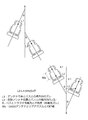
従来の技術では、自律走行車が前進移動する際に、自律走行車が目標パス上を精確にトレースするための誘導制御方法について展開されていた。しかし、圃場サイズや形状によっては、前後進の切替を頻繁に行う必要がある場合に生じる後進移動時の誘導制御方法については考慮されていなかった。前後進の切替操作が生じるケースとしては、図17に示すように、(1)畦際での旋回、(2)圃場から出る直前の方向変換、枕地仕上げがあり、特に狭い圃場で作業を行う際には頻繁に生じることが知られている。
In the conventional technology, a guidance control method for allowing an autonomous vehicle to accurately trace a target path when the autonomous vehicle moves forward has been developed. However, depending on the size and shape of the field, the guidance control method at the time of reverse movement that occurs when frequent forward / reverse switching is required has not been considered. As shown in FIG. 17, there are (1) turning at the edge, (2) direction change just before leaving the field, and headland finishing, as shown in FIG. It is known to occur frequently when done.
以上のように、無人走行車や自律型ロボット走行車が、予め定義されて設計された(前進移動、旋回、後進移動を含む)静的パスデータに基づいて独立的に機能するべく走行制御する自動誘導システムが求められている。
As described above, the unmanned traveling vehicle or the autonomous robot traveling vehicle performs traveling control so as to function independently based on the static path data (including forward movement, turning, and backward movement) that is defined and designed in advance. There is a need for an automated guidance system.
本発明は、自律走行車の誘導制御方法に関する。より詳しくは、機能的な操作を自律走行車自身で行う無人走行を容易化した自律走行型のロボットトラクタに関する。例えば、自律走行型のロボットトラクタは、無人走行を容易化するとともに、トラクタによる農作業を自律的に実行するものである。そのようなロボットトラクタの誘導の主たる目的は、一連の耕作作業を完全な自律操作で行うことであり、トラクタの位置を制御し、トラクタを予め定義された経路に従って(種々の作業を行いつつ)移動させることである。
実際の農業に適用する際には、異なる土壌条件及び異なる障害物が存在する耕作領域において横方向の偏差及び進行方向の偏差を低く抑える必要がある。自律操作の間には、オペレータは、耕作条件に基づいて速度及びヒッチ操作を変更することができる。 The present invention relates to a guidance control method for an autonomous vehicle. More specifically, the present invention relates to an autonomous traveling robot tractor that facilitates unmanned traveling in which a functional operation is performed by the autonomous traveling vehicle itself. For example, an autonomously traveling robot tractor facilitates unmanned traveling and autonomously performs agricultural work by the tractor. The main purpose of guiding such a robot tractor is to perform a series of tilling operations with fully autonomous operation, controlling the position of the tractor and following the tractor in a predefined path (while performing various operations) It is to move.
When applied to actual agriculture, it is necessary to keep the lateral deviation and the traveling direction deviation low in a cultivation area where different soil conditions and different obstacles exist. During autonomous operation, the operator can change the speed and hitch operation based on the cultivation conditions.
自律走行型のロボットトラクタは、圃場を走行し、電子制御ユニット(ECU)に保存されたアルゴリズムに従って機能を発揮する。走行車の作業走行は、ECUに保存されたパスデータ、及び、GPS技術を活用したGNSSセンサを介して受信された信号に基づいて行われる。つまり、自律誘導は、ロボットトラクタを設計された経路に沿って走行させることができる。
An autonomously traveling robot tractor travels in the field and performs its function according to an algorithm stored in an electronic control unit (ECU). The traveling of the traveling vehicle is performed based on path data stored in the ECU and a signal received via a GNSS sensor utilizing GPS technology. That is, the autonomous guidance can cause the robot tractor to travel along the designed route.
本発明の第一態様は、衛星測位システムを利用して走行車の位置を測位しながら自律して走行及び作業を行う自律走行車の誘導制御システムであって、前記自律走行車を後進移動させる際に、前記衛星測位システムのアンテナ位置よりも所定距離後方に仮想アンテナ位置を設定し、その仮想アンテナ位置における目標パスからの横方向の偏差を用いてラテラル制御を行うことを特徴とする。
A first aspect of the present invention is a guidance control system for an autonomous traveling vehicle that autonomously travels and works while positioning a traveling vehicle using a satellite positioning system, and moves the autonomous traveling vehicle backward. In this case, a virtual antenna position is set behind a predetermined distance from the antenna position of the satellite positioning system, and lateral control is performed using a lateral deviation from the target path at the virtual antenna position.
本発明の第一態様に係る好ましい実施形態では、前記自律走行車の誘導制御システムは、前記仮想アンテナ位置を選択しながら誘導制御信号を前記自律走行車に伝送するアンテナ位置補正モジュールと、前記目標パスに基づいて前記自律走行車の走行を追跡するための誘導制御信号を生成する自律走行車走行モジュールと、前記アンテナ位置補正モジュールと接続され、そのラテラル制御を行うラテラル制御モジュールと、前記自律走行車走行モジュールと接続され、予測される向首角と実際の向首角との差を修正することで前記自律走行車の向首角のずれを制御するヘディング制御モジュールと、前記ラテラル制御モジュール及びヘディング制御モジュールと接続され、ステアリング制御信号を生成するヨーレート制御モジュールと、を備える。
In a preferred embodiment according to the first aspect of the present invention, the autonomous vehicle guidance control system includes an antenna position correction module that transmits a guidance control signal to the autonomous vehicle while selecting the virtual antenna position, and the target. An autonomous traveling vehicle traveling module that generates a guidance control signal for tracking traveling of the autonomous traveling vehicle based on a path, a lateral control module that is connected to the antenna position correction module and performs lateral control thereof, and the autonomous traveling A heading control module that is connected to the vehicle travel module and controls a deviation of the head angle of the autonomous vehicle by correcting a difference between a predicted head angle and an actual head angle; the lateral control module; A yaw rate control module connected to the heading control module and generating a steering control signal; Obtain.
前記自律走行車の誘導制御システムは、前記自律走行車走行モジュールと接続され、前記目標パスに含まれる曲線経路の断続性に起因する前記目標パスからの偏差を修正するフィードフォワード制御モジュールをさらに備えることが望ましい。
The guidance control system for an autonomous vehicle further includes a feedforward control module that is connected to the autonomous vehicle traveling module and corrects a deviation from the target path due to the intermittentness of a curved path included in the target path. It is desirable.
本発明の第二態様は、衛星測位システムを利用して走行車の位置を測位しながら自律して走行及び作業を行う自律走行車の誘導制御システムであって、前記自律走行車を前進移動させる際に、前記衛星測位システムのアンテナ位置よりも所定距離前方に仮想アンテナ位置を設定し、その仮想アンテナ位置における目標パスからの横方向の偏差を用いてラテラル制御を行う。
A second aspect of the present invention is an autonomous traveling vehicle guidance control system that autonomously travels and works while positioning a traveling vehicle using a satellite positioning system, and moves the autonomous traveling vehicle forward. At this time, a virtual antenna position is set a predetermined distance ahead of the antenna position of the satellite positioning system, and lateral control is performed using a lateral deviation from the target path at the virtual antenna position.
本発明の好ましい実施形態では、前記自律走行車は、目標パスからの横方向の偏差又は向首角の偏差が所定値を超えた場合に、停止され、自律走行を終了する。
In a preferred embodiment of the present invention, the autonomous vehicle is stopped when the lateral deviation from the target path or the deviation of the head angle exceeds a predetermined value, and terminates autonomous running.
本発明の好ましい実施形態では、前記自律走行車は、遠隔操作によるオーバーライド制御操作によって自律走行を停止可能であり、その停止位置から自律走行を再開可能である。
In a preferred embodiment of the present invention, the autonomous traveling vehicle can stop autonomous traveling by an override control operation by remote control, and can resume autonomous traveling from the stop position.
本発明の誘導制御システムによれば、自律走行車の前進移動、旋回、及び、後進移動において、予め設計された目標パスに従った走行を実現できる。
According to the guidance control system of the present invention, it is possible to realize traveling in accordance with a predesigned target path in forward movement, turning, and reverse movement of an autonomous vehicle.
上述の技術思想及び本発明の他の特徴は、これに続く詳細な説明に記載され、そこでは添付の図面を参照して説明が行われる。
The above-described technical concept and other features of the present invention will be described in the following detailed description, which will be described with reference to the accompanying drawings.
本発明の実施形態は、添付の図面を参照して以下に記載される。しかし、本発明は本実施形態に限定されるものではない。大きさ、形状、配置、個数、及び本発明の装置に含まれる種々の要素の構成については、好適な例を示しているに過ぎず、本発明の範囲を逸脱しない範囲で当業者による様々な改良が可能である。従って、本発明の実施形態は、当業者に対して本発明をより明確に説明するために記載されているに過ぎない。添付の図面において、同様の符号は同様の構成要素を示している。
Embodiments of the present invention are described below with reference to the accompanying drawings. However, the present invention is not limited to this embodiment. The size, shape, arrangement, number, and configuration of various elements included in the apparatus of the present invention are merely preferred examples, and various modifications can be made by those skilled in the art without departing from the scope of the present invention. Improvements are possible. Accordingly, the embodiments of the present invention are merely described to more clearly explain the present invention to those skilled in the art. In the accompanying drawings, like numerals indicate like components.
本明細書では、複数箇所において、「ある」、「一つの」、又は、「複数の」実施形態について言及される。これは、そのような参照が同一の実施形態であること、若しくは、特徴要件が単一の実施形態に適用されることを必ずしも示唆するものではない。つまり、異なる実施形態の一つの特徴は、他の実施形態に対して複合されるものである。
In this specification, reference is made to “a”, “a” or “plural” embodiments in multiple places. This does not necessarily imply that such references are the same embodiment or that the feature requirements apply to a single embodiment. That is, one feature of different embodiments is compounded with respect to other embodiments.
ここで用いられている「ある」、「一つの」、及び「その」という単数表記は、他の表記を伴わなくとも同時に複数表記も含むことを意図している。さらに、明細書中の「含む」、「備える」、「含んでいる」、「備えている」等の記載は、特徴、完成形、工程、操作、要素、及び/又は構成要素の存在を示すものであり、その他の一つ又は複数の特徴、完成形、工程、操作、要素、構成要素、及び/又はそれらの集合の存在又は追加を排除するものではない。ある要素が「接続される」又は「結合される」ものとして記載される場合、他の要素に直接的に接続又は結合されても良いし、さらに他の要素を介在させても良い。さらに、「接続される」又は「結合される」という記載は、動作的に行われるものも含んでいる。ここで用いられるように、「及び/又は」という記載は、一つ又は複数の関連する部材の任意の又は全ての組み合わせ及び配置を含んでいるものとする。
As used herein, the singular notation “a”, “one”, and “that” is intended to include a plurality of notations at the same time without any other notation. In addition, descriptions such as “including”, “comprising”, “including”, “comprising” in the specification indicate the presence of features, finished forms, processes, operations, elements, and / or components. And does not exclude the presence or addition of one or more other features, completions, processes, operations, elements, components, and / or collections thereof. When an element is described as being “connected” or “coupled”, it may be directly connected or coupled to another element, and further elements may intervene. Furthermore, the phrase “connected” or “coupled” includes what is operatively performed. As used herein, the phrase “and / or” is intended to include any and all combinations and arrangements of one or more associated members.
他の方法で定義されていない場合、技術用語及び科学用語を含む全ての用語は、本発明の属する分野の通常の知識を有する者が共通して理解される意味で用いられる。さらに、一般的な辞書での定義の用語は、関連した技術の文脈内での一貫した定義を有するものとして理解されるべきであり、ここで明確に定義されているにも関わらず、理想的な意味又は過度に形式張った意味として理解されるべきではない。
Unless defined otherwise, all terms, including technical and scientific terms, are used in a manner that is commonly understood by those with ordinary knowledge in the field to which the present invention belongs. Furthermore, the terminology definitions in a general dictionary should be understood as having a consistent definition within the context of the relevant technology, and are ideal though they are clearly defined here. It should not be understood as a meaning or an overly formal meaning.
本発明は、自律走行車の誘導制御方法に関する。より詳しくは、機能的な操作を自律走行車自身で行う無人走行を容易化した自律走行型のロボットトラクタに関する。例えば、自律走行型のロボットトラクタは、無人走行を容易化するとともに、トラクタによる農作業を自律的に実行するものである。そのようなロボットトラクタの誘導の主たる目的は、一連の耕作作業を完全な自律操作で行うことであり、トラクタの位置を制御し、トラクタを予め定義された経路に従って(種々の作業を行いつつ)移動させることである。
実際の農業に適用する際には、異なる土壌条件及び異なる障害物が存在する耕作領域において横方向の偏差及び進行方向の偏差を低く抑える必要がある。自律操作の間には、オペレータは、耕作条件に基づいて速度及びヒッチ操作を変更することができる。 The present invention relates to a guidance control method for an autonomous vehicle. More specifically, the present invention relates to an autonomous traveling robot tractor that facilitates unmanned traveling in which a functional operation is performed by the autonomous traveling vehicle itself. For example, an autonomously traveling robot tractor facilitates unmanned traveling and autonomously performs agricultural work by the tractor. The main purpose of guiding such a robot tractor is to perform a series of tilling operations with fully autonomous operation, controlling the position of the tractor and following the tractor in a predefined path (while performing various operations) It is to move.
When applied to actual agriculture, it is necessary to keep the lateral deviation and the traveling direction deviation low in a cultivation area where different soil conditions and different obstacles exist. During autonomous operation, the operator can change the speed and hitch operation based on the cultivation conditions.
実際の農業に適用する際には、異なる土壌条件及び異なる障害物が存在する耕作領域において横方向の偏差及び進行方向の偏差を低く抑える必要がある。自律操作の間には、オペレータは、耕作条件に基づいて速度及びヒッチ操作を変更することができる。 The present invention relates to a guidance control method for an autonomous vehicle. More specifically, the present invention relates to an autonomous traveling robot tractor that facilitates unmanned traveling in which a functional operation is performed by the autonomous traveling vehicle itself. For example, an autonomously traveling robot tractor facilitates unmanned traveling and autonomously performs agricultural work by the tractor. The main purpose of guiding such a robot tractor is to perform a series of tilling operations with fully autonomous operation, controlling the position of the tractor and following the tractor in a predefined path (while performing various operations) It is to move.
When applied to actual agriculture, it is necessary to keep the lateral deviation and the traveling direction deviation low in a cultivation area where different soil conditions and different obstacles exist. During autonomous operation, the operator can change the speed and hitch operation based on the cultivation conditions.
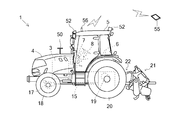
以下、図1から図3を参照して、本発明に係る自律走行車の一実施形態であるロボットトラクタ(以下、単に「トラクタ」)1、及び、トラクタ1の誘導制御を行う誘導制御システム2について説明する。トラクタ1は、無人で自律して走行可能かつ作業可能である。具体的には、トラクタ1は、誘導制御システム2による制御を受けて、所定の経路に沿って移動しつつ、経路上の所定箇所で作業を行う。
1 to 3, a robot tractor (hereinafter simply “tractor”) 1 that is an embodiment of an autonomous vehicle according to the present invention, and a guidance control system 2 that performs guidance control of the tractor 1 will be described. Will be described. The tractor 1 is unmanned and autonomously capable of traveling and working. Specifically, the tractor 1 receives the control by the guidance control system 2 and moves along a predetermined route while performing work at a predetermined location on the route.
トラクタ1は、エンジン3を収容するボンネット4、及び、ボンネット4の後方に配置されるキャビン5を備える。キャビン5内には、運転席6と、その前方に配置されるダッシュボード7が設けられ、運転席6の周囲及びダッシュボード7には、ステアリングハンドル8、主変速レバー9、前後進切替レバー10、昇降レバー11、PTO変速レバー12等の操作具が設けられる。つまり、トラクタ1は、オペレータによる運転が可能な構成を有している。
The tractor 1 includes a bonnet 4 that houses the engine 3 and a cabin 5 that is arranged behind the bonnet 4. In the cabin 5, a driver's seat 6 and a dashboard 7 disposed in front of the driver's seat 6 are provided. A steering handle 8, a main transmission lever 9, and a forward / reverse switching lever 10 are provided around the driver's seat 6 and on the dashboard 7. Further, operating tools such as an elevating lever 11 and a PTO speed change lever 12 are provided. That is, the tractor 1 has a configuration that can be operated by an operator.
運転席6の下方にミッションケース15が配置される。エンジン3の動力がミッションケース15内の変速装置16により変速されて、フロントアクスル17に支承される前輪18及びリヤアクスル19に支承される後輪20、並びに、作業機21を駆動するPTO軸に伝達される。作業機21は、機体後部に三点リンク機構22を介して装着されており、三点リンク機構22の作動(ヒッチ操作)によって作業機21を上下方向に移動可能、かつ、左右に傾斜可能に構成されている。
A mission case 15 is arranged below the driver's seat 6. The power of the engine 3 is shifted by the transmission 16 in the transmission case 15 and transmitted to the front wheels 18 supported by the front axle 17 and the rear wheels 20 supported by the rear axle 19 and the PTO shaft that drives the work implement 21. Is done. The work machine 21 is attached to the rear part of the machine body via a three-point link mechanism 22, and the work machine 21 can be moved up and down and tilted left and right by the operation (hitch operation) of the three-point link mechanism 22. It is configured.
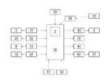
ロボットトラクタ1には、その運転を制御するための電子制御ユニット(ECU)30が搭載されている。ECU30には、エンジン3の回転数を検出する回転数センサ31、後輪20の回転数を検出する車速センサ32、ステアリングハンドル8の回動角(つまり前輪18の回動角)を検出する操舵角センサ33、前後進切替レバー10の操作位置を検出するポジションセンサ34等のセンサ類が接続されており、これらのセンサによる検出値が検出信号に変換されてECU30に送信される。
また、ECU30には、エンジン3の回転数を制御するガバナ装置40、トラクタ1の速度を制御する変速装置16、トラクタ1の進行方向(操舵角)を制御する操向装置41、三点リンク機構22を制御する昇降装置42等の各アクチュエータが接続されている。ECU30は、これらのアクチュエータの作動を制御することで、トラクタ1の運転を自動的に制御することが可能である。そして、ECU30は、誘導制御システム2を含むことで、誘導制御システム2に基づいたトラクタ1の自律運転を可能にしている。 Therobot tractor 1 is equipped with an electronic control unit (ECU) 30 for controlling its operation. The ECU 30 includes a rotation speed sensor 31 that detects the rotation speed of the engine 3, a vehicle speed sensor 32 that detects the rotation speed of the rear wheel 20, and a steering wheel that detects the rotation angle of the steering handle 8 (that is, the rotation angle of the front wheel 18). Sensors such as an angle sensor 33 and a position sensor 34 for detecting the operation position of the forward / reverse switching lever 10 are connected, and detection values by these sensors are converted into detection signals and transmitted to the ECU 30.
TheECU 30 includes a governor device 40 that controls the rotational speed of the engine 3, a transmission device 16 that controls the speed of the tractor 1, a steering device 41 that controls the traveling direction (steering angle) of the tractor 1, and a three-point link mechanism. Each actuator such as an elevating device 42 for controlling 22 is connected. The ECU 30 can automatically control the operation of the tractor 1 by controlling the operation of these actuators. The ECU 30 includes the guidance control system 2 to enable autonomous operation of the tractor 1 based on the guidance control system 2.
また、ECU30には、エンジン3の回転数を制御するガバナ装置40、トラクタ1の速度を制御する変速装置16、トラクタ1の進行方向(操舵角)を制御する操向装置41、三点リンク機構22を制御する昇降装置42等の各アクチュエータが接続されている。ECU30は、これらのアクチュエータの作動を制御することで、トラクタ1の運転を自動的に制御することが可能である。そして、ECU30は、誘導制御システム2を含むことで、誘導制御システム2に基づいたトラクタ1の自律運転を可能にしている。 The
The
トラクタ1のボンネット4の上面に衛星測位システムであるGNSSからの信号を受信するGNSSアンテナ50が配置されている。GNSSアンテナ50は、測位衛星からの信号を受信することで、トラクタ1の位置を測位する。これとともに、GNSSアンテナ50は、ヘディングセンサを内蔵することでトラクタ1の向首角を同時に検出する。GNSSアンテナ50は、ECU30と接続されており、測位衛星からの検出信号をECU30に送信する。つまり、ECU30によって、トラクタ1の位置及び向首角が取得される。
なお、測位衛星を利用したGNSSシステムとしては、GPS技術を活用した衛星測位システムが代表例として挙げられる。例えば、GPS衛星を用いた測位に加えて、準天頂衛星、グロナス衛星等の他の衛星を用いたシステムを利用することも可能である、また、GPS測位としては、単独測位、相対測位、DGPS測位、RTK-GPS測位等を採用することができる。 AGNSS antenna 50 that receives a signal from a GNSS that is a satellite positioning system is disposed on the upper surface of the bonnet 4 of the tractor 1. The GNSS antenna 50 measures the position of the tractor 1 by receiving a signal from a positioning satellite. At the same time, the GNSS antenna 50 simultaneously detects the head angle of the tractor 1 by incorporating a heading sensor. The GNSS antenna 50 is connected to the ECU 30 and transmits a detection signal from the positioning satellite to the ECU 30. That is, the position and the head angle of the tractor 1 are acquired by the ECU 30.
A typical example of a GNSS system that uses positioning satellites is a satellite positioning system that uses GPS technology. For example, in addition to positioning using GPS satellites, a system using other satellites such as a quasi-zenith satellite and a Glonus satellite can be used. Also, as GPS positioning, independent positioning, relative positioning, DGPS Positioning, RTK-GPS positioning, etc. can be employed.
なお、測位衛星を利用したGNSSシステムとしては、GPS技術を活用した衛星測位システムが代表例として挙げられる。例えば、GPS衛星を用いた測位に加えて、準天頂衛星、グロナス衛星等の他の衛星を用いたシステムを利用することも可能である、また、GPS測位としては、単独測位、相対測位、DGPS測位、RTK-GPS測位等を採用することができる。 A
A typical example of a GNSS system that uses positioning satellites is a satellite positioning system that uses GPS technology. For example, in addition to positioning using GPS satellites, a system using other satellites such as a quasi-zenith satellite and a Glonus satellite can be used. Also, as GPS positioning, independent positioning, relative positioning, DGPS Positioning, RTK-GPS positioning, etc. can be employed.
トラクタ1には、前方、側方、又は後方に障害物があるかどうかを検出する障害物センサ51が取り付けられている。障害物センサ51は、レーザセンサ、超音波センサ等によって構成され、トラクタ1の前方、側方、及び後方に存在する障害物を認識し、検出信号を生成する。また、トラクタ1は、前方、側方、及び後方を撮影するカメラ52が取り付けられる。障害物センサ51及びカメラ52は、ECU30と接続されており、ECU30に検出結果を送信する。
The tractor 1 is provided with an obstacle sensor 51 that detects whether there is an obstacle ahead, side, or rear. The obstacle sensor 51 is constituted by a laser sensor, an ultrasonic sensor, or the like, recognizes obstacles existing in front, side, and rear of the tractor 1 and generates a detection signal. Further, the tractor 1 is attached with a camera 52 for photographing the front, side, and rear. The obstacle sensor 51 and the camera 52 are connected to the ECU 30 and transmit a detection result to the ECU 30.
トラクタ1の誘導制御システム2を遠隔操作によって制御する際には、タブレット55等の無線機器が用いられる。タブレット55からの制御信号は、トラクタ1のキャビン5の上面に配置されるアンテナ56によって受信される。アンテナ56は、ECU30と接続されており、制御信号をECU30に送信する。
When the guidance control system 2 of the tractor 1 is controlled by remote operation, a wireless device such as a tablet 55 is used. A control signal from the tablet 55 is received by the antenna 56 disposed on the upper surface of the cabin 5 of the tractor 1. The antenna 56 is connected to the ECU 30 and transmits a control signal to the ECU 30.
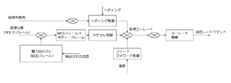
図4は、自律誘導システムを構成する各モジュールの概略図を示す。本実施形態では、GPSが姿勢角度信号及びロボットトラクタバス上のCANメッセージフォーマット内で検出した位置信号を送信する。ECU内のプラットフォームでCAN信号を受信し、それを物理信号に変換する。この物理信号は次に自律誘導モデルに伝送される。プラットフォームのソフトウェアは、フラッシュファイル内に存在し、実行時に自律誘導に関する詳細な静的パスを生成する静的パスデータを読み込む。
自律誘導モデルは、検出された信号及び静的パスデータに基づいて所望のコマンドを算出し、トラクタバスの操舵制御システムにコマンドを送信する。オペレータは、タブレット端末によって自律誘導モデルにロボットトラクタ上のオーバーライド制御信号を送信可能であり、それを受けた自律誘導モデルは、パスジオメトリに基づいてオーバーライド制御信号に応答する。このオーバーライド制御信号コマンドは、トラクタバスのECUによって送信される。 FIG. 4 shows a schematic diagram of each module constituting the autonomous guidance system. In this embodiment, the GPS transmits the attitude angle signal and the position signal detected in the CAN message format on the robot tractor bus. The CAN signal is received by the platform in the ECU and converted into a physical signal. This physical signal is then transmitted to the autonomous guidance model. The platform software is present in the flash file and reads static path data that generates a detailed static path for autonomous guidance at runtime.
The autonomous guidance model calculates a desired command based on the detected signal and static path data, and transmits the command to the steering control system of the tractor bus. The operator can transmit an override control signal on the robot tractor to the autonomous guidance model by the tablet terminal, and the autonomous guidance model receiving the response responds to the override control signal based on the path geometry. This override control signal command is transmitted by the ECU of the tractor bus.
自律走行型のロボットトラクタの制御則は、横方向の位置偏差を低減すること、及び走行車の向首角(方位)を制御することを目的に設計されている。誘導システムは、ロボットトラクタが自律モードで作業することを容易化するものである。
The control law of the autonomously traveling robot tractor is designed for the purpose of reducing the lateral position deviation and controlling the heading angle (azimuth) of the traveling vehicle. The guidance system makes it easier for the robot tractor to work in autonomous mode.
[1.トラクタの傾きに起因する位置ズレ補正]
GNSSアンテナは、トラクタの上面に配置されている。これにより、走行車の傾きに起因して検出位置にズレが生じる。この位置ズレは、次の数式を用いた姿勢角度補正によって補正される。

[1. Misalignment correction caused by tractor tilt]
The GNSS antenna is disposed on the upper surface of the tractor. Thereby, the detection position is displaced due to the inclination of the traveling vehicle. This positional deviation is corrected by posture angle correction using the following mathematical formula.
GNSSアンテナは、トラクタの上面に配置されている。これにより、走行車の傾きに起因して検出位置にズレが生じる。この位置ズレは、次の数式を用いた姿勢角度補正によって補正される。
The GNSS antenna is disposed on the upper surface of the tractor. Thereby, the detection position is displaced due to the inclination of the traveling vehicle. This positional deviation is corrected by posture angle correction using the following mathematical formula.
[2.トラクタ走行]
トラクタ走行のアルゴリズムによって、誘導システムは、読み込まれた静的パスデータに基づいた走行車の走行を容易に追跡することができる。経路の追跡方法は、直線経路と曲線経路との間で異なっている。それは、曲線経路における走行では走行車の向首角の影響が重要となるが、直線経路における走行ではラテラル制御が優先されるためである。 [2. Tractor travel]
The tractor travel algorithm allows the guidance system to easily track the travel of the vehicle based on the read static path data. The path tracking method is different between a straight path and a curved path. This is because the influence of the heading angle of the traveling vehicle is important when traveling on a curved route, but lateral control is prioritized when traveling on a straight route.
[測地からNED座標系への変換]
測地座標系の緯度、経度、高度で検出されるトラクタの位置、及び、走行車の静的パスの位置データが地平直交座標系であるNED座標系に変換される。NED座標データは、位置偏差及び向首角偏差を算出するために用いられる。 [Conversion from geodetic to NED coordinate system]
The position of the tractor detected by the latitude, longitude and altitude of the geodetic coordinate system, and the position of the static path of the traveling vehicle are converted into the NED coordinate system which is the horizon orthogonal coordinate system. The NED coordinate data is used to calculate the position deviation and the head angle deviation.
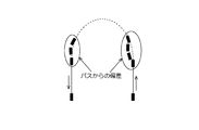
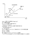
図5は、直線経路中の自律走行車の軌道を示すグラフである。この場合の誘導方法は、目標とするヨーレートがLOSレートをゼロにすることで引き出されるように、主に並行走行に基づいて行われる。LOSレートをゼロにするために、走行車はLOSベクトル内で走行する必要がある。
FIG. 5 is a graph showing the track of an autonomous vehicle in a straight route. The guidance method in this case is mainly performed based on parallel running so that the target yaw rate is derived by setting the LOS rate to zero. In order to make the LOS rate zero, the traveling vehicle needs to travel within the LOS vector.
図6は、曲線経路中の自律走行車の軌道を示すグラフである。ヘディング制御では、目標とする向首角が、並行走行方式ではなくパスジオメトリから引き出される。
FIG. 6 is a graph showing the track of an autonomous vehicle in a curved path. In heading control, the target heading angle is derived from the path geometry instead of the parallel running method.
経路追跡のアルゴリズムは、現在のトラクタの位置に基づいて、以下の(1)から(4)に示す情報を静的パスから抜き取り、抜き取った情報を他の誘導モジュールに提供するものである。
(1)目標パスデータ、旋回角、始動点及び停止点
(2)作業領域(耕作領域)及び枕地領域
(3)運転状況(直進、旋回等)
(4)前進移動又は後進移動
上記情報は、自律した機能的作業、及び、異なる誘導フェーズを制御する制御モジュールに用いられる。 The route tracking algorithm extracts the information shown in the following (1) to (4) from the static path based on the current position of the tractor, and provides the extracted information to other guidance modules.
(1) Target path data, turning angle, starting point and stopping point (2) Work area (cultivation area) and headland area (3) Driving situation (straight, turning, etc.)
(4) Forward movement or backward movement The above information is used for autonomous functional work and control modules that control different guidance phases.
図7は、後進移動時の自律走行車の軌道を示すグラフである。本実施形態では、目標の向首角及び横方向の偏差は、後進移動時の実施形態に対して示されている。
FIG. 7 is a graph showing the track of the autonomous vehicle during backward movement. In this embodiment, the target azimuth and lateral deviation are shown relative to the embodiment during reverse travel.
[3.NED座標系からトラクタ本体への変換]
位置偏差は、オイラー角を用いて、ローカルの本体フレームに変換される。これにより、グローバル座標系での走行車走行の制御を簡単にし、かつ、精確にできる。 [3. Conversion from NED coordinate system to tractor body]
The position deviation is converted into a local body frame using Euler angles. Thereby, it is possible to simplify and accurately control the traveling of the traveling vehicle in the global coordinate system.
[4.制御方法]
図8は、全体的な制御方法のブロック図である。本実施形態での発展した制御則は、フィードバック制御ループ及びフィードフォワード制御ループを伴うカスケード制御システムである。 [4. Control method]
FIG. 8 is a block diagram of the overall control method. The developed control law in this embodiment is a cascade control system with a feedback control loop and a feedforward control loop.
図8は、全体的な制御方法のブロック図である。本実施形態での発展した制御則は、フィードバック制御ループ及びフィードフォワード制御ループを伴うカスケード制御システムである。 [4. Control method]
FIG. 8 is a block diagram of the overall control method. The developed control law in this embodiment is a cascade control system with a feedback control loop and a feedforward control loop.
[フィードバック制御]
走行車の向首角の偏差だけでなく横方向の偏差を改善するために、ラテラル制御は、アウターループ内でヘディング制御と並行して実行されるように設計される。ヨーレート制御は、操舵レートを取得し、全体的な誘導システムのロバスト性を向上するために、インナーループ内で実行される。このインナーループ制御は、土壌の起伏、センサーノイズ、電子油圧制御の操舵システムの非線形性等の種々の外乱から影響を受けるシステムの感度を制御する。 [Feedback control]
In order to improve the lateral deviation as well as the heading deviation, the lateral control is designed to be executed in parallel with the heading control in the outer loop. Yaw rate control is performed in the inner loop to obtain the steering rate and improve the robustness of the overall guidance system. This inner loop control controls the sensitivity of the system affected by various disturbances such as soil undulations, sensor noise, and non-linearity of the electrohydraulic control steering system.
[ラテラル制御]
横方向の偏差(Yerror)は、予め定義されたパスからトラクタまでの最小距離で算出される。ラテラル制御では、横方向の偏差は、NEDフレーム内で算出され、コマンドとして本体フレームに変換される。つまり、横方向の偏差は、本体Yフレーム内でのものとして扱われる。 [Lateral control]
The horizontal deviation (Yerror) is calculated by the minimum distance from the predefined path to the tractor. In the lateral control, the lateral deviation is calculated within the NED frame and converted into a main frame as a command. That is, the lateral deviation is treated as being in the main body Y frame.
[ヘディング制御]
ヘディング制御では、向首角の偏差を制御する。向首角の偏差は、目標向首角と実際のトラクタの向首角との差として算出される。ヘディング制御は、曲線経路走行中に優先される。 [Heading control]
In heading control, the head angle deviation is controlled. The deviation of the head angle is calculated as the difference between the target head angle and the actual head angle of the tractor. Heading control is prioritized during traveling on a curved path.
[ヨーレート制御]
ヨーレート制御は、インナーループ内で実行される。そして、アウターループコントローラの出力、つまり横方向の偏差及び向首角は、算出されたヨーレートの参照入力値と比較される。ヨーレート制御の出力は、操舵システムに入力される操舵レートのコマンドである。 [Yaw rate control]
The yaw rate control is executed in the inner loop. The output of the outer loop controller, that is, the lateral deviation and the head angle are compared with the calculated reference input value of the yaw rate. The output of the yaw rate control is a steering rate command input to the steering system.
ラテラル制御、ヘディング制御、及び、ヨーレート制御の制御則は、PD制御システムである。

The control laws for lateral control, heading control, and yaw rate control are PD control systems.
[フィードフォワード制御システム]
図9は、曲線経路の不連続性に起因してパスから脱線した際の軌道を示す。曲線経路の不連続性は、直線部分と曲線部分の接続箇所に存在し、これにより、走行車がパスから外れることとなる。フィードバック制御に加えて、フィードフォワードコントローラは、直線から曲線及び曲線から直線へのパスの遷移中のシステムのオーバーシュートを排除するように設計される。フィードフォワード制御は、旋回角及び速度に関する機能である。 [Feed forward control system]
FIG. 9 shows the trajectory when derailing from the path due to the discontinuity of the curved path. The discontinuity of the curved route exists at the connection portion between the straight line portion and the curved portion, and thereby the traveling vehicle deviates from the path. In addition to feedback control, the feedforward controller is designed to eliminate system overshoot during straight-to-curve and curved-to-straight path transitions. The feedforward control is a function related to the turning angle and speed.
[コントロールゲインのスケジューリング]
コントロールゲインのスケジューリングは、外乱に対するシステムの安定性を最適化し、エラーを低減するために実行されている。コントロールゲインは、走行車の速度に関する機能に特化している。 [Control gain scheduling]
Control gain scheduling is performed to optimize system stability against disturbances and reduce errors. The control gain is specialized in the function related to the speed of the traveling vehicle.
[5.GNSSアンテナ位置補正]
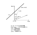
図10は、GNSSアンテナ位置の補正の様子を示す。これは、自律走行車の誘導制御を実現する際に重要な特徴である。アンテナ位置が重要な役割を果たすときは、過渡的なフェーズである。つまり、GNSSアンテナがトラクタの前部に配置されている場合、横方向の偏差はより早く検出される。これにより、システム遅れを減らし、全体的な過渡応答特性を向上することができる。
しかしながら、後進制御時には、横方向の偏差は、トラクタの後部と比較して遅く検出される。このため、過渡応答を向上することを目的として、GNSSアンテナの位置での横方向の偏差(L1)、及び、向首角の偏差に基づいて、後部位置における横方向の偏差(L2)を算出する。つまり、トラクタの後部位置を仮想アンテナ位置として設定し、後進制御を行うことで過渡応答を向上している。 [5. GNSS antenna position correction]
FIG. 10 shows how the GNSS antenna position is corrected. This is an important feature when realizing guidance control of an autonomous vehicle. When antenna position plays an important role, it is a transitional phase. That is, when the GNSS antenna is arranged at the front of the tractor, the lateral deviation is detected earlier. Thereby, system delay can be reduced and the overall transient response characteristic can be improved.
However, during reverse control, the lateral deviation is detected later than the rear part of the tractor. Therefore, in order to improve the transient response, the lateral deviation (L2) at the rear position is calculated based on the lateral deviation (L1) at the position of the GNSS antenna and the deviation of the head angle. To do. That is, the rear position of the tractor is set as the virtual antenna position, and the reverse response is performed to improve the transient response.
[6.誘導フェーズ]
あらゆる圃場及び種々の作業に対する自律的な操作を実現するために、異なる誘導フェーズが必要となる。その誘導フェーズには、次に示す制御方法が用いられる。
(1)直進
直進制御フェーズでは、インナーループ制御でヨーレート制御が行われる間、アウターループ制御でラテラル制御及びヘディング制御が行われる。ヘディング制御は、パスジオメトリに基づいた目標向首角を入力とする。
(2)旋回
旋回制御フェーズでは、アウターループ制御で、ラテラル制御、ヘディング制御及びフィードフォワード制御が行われ、インナーループ制御でヨーレート制御が行われる。ヘディング制御は、パスジオメトリに基づいた目標向首角を入力とする。
(3)後進移動
後進制御フェーズでは、後方への移動が始まる前に、操舵角がゼロとなるように第一の操舵角制御が行われる。後進制御では、横方向の偏差は、前輪ではなく後輪位置で算出される。 [6. Guidance phase]
Different guidance phases are required to realize autonomous operation for every field and various tasks. The following control method is used for the induction phase.
(1) Straight traveling In the straight traveling control phase, lateral control and heading control are performed by outer loop control while yaw rate control is performed by inner loop control. The heading control receives a target head angle based on the path geometry.
(2) Turning In the turning control phase, lateral control, heading control, and feedforward control are performed in outer loop control, and yaw rate control is performed in inner loop control. The heading control receives a target head angle based on the path geometry.
(3) Reverse movement In the reverse control phase, the first steering angle control is performed so that the steering angle becomes zero before the backward movement starts. In reverse control, the lateral deviation is calculated not at the front wheel but at the rear wheel position.
[7.自律的な機能操作]
自律誘導システムは、次に示す機能操作を行う。
(1)耕作領域、非耕作領域の何れか、読み込まれた静的パス、及び、走行車の位置データに基づいた自律的なヒッチ操作及びPTO操作。
(2)自律モードは、トラクタが始点にいない場合には始められない。この機能では、ECU内で予め定義された静的パスの始点に対するロボットトラクタの姿勢の偏りに従って、実際の位置を確認することが求められる。
(3)このシステムでは、パスの偏差(横方向の偏差及び向首角の偏差)が所定値を超えないことが求められる。仮に、この所定値を超えた場合は、自律モードが停止される。
(4)ロボットトラクタの自律モードは、耕作の終点で終了する。これは、保存された走行パスに関する情報及びトラクタの実際の位置に基づいて実現される。
(5)センサ(障害物センサ又はカメラ)によって障害物が検出された場合も、自律操作を終了する。 [7. Autonomous function operation]
The autonomous guidance system performs the following functional operations.
(1) Autonomous hitch operation and PTO operation based on any of the cultivated area and the non-cultivated area, the read static path, and the position data of the traveling vehicle.
(2) Autonomous mode cannot be started if the tractor is not at the starting point. In this function, it is required to confirm the actual position according to the bias of the posture of the robot tractor with respect to the start point of the static path defined in advance in the ECU.
(3) In this system, it is required that the deviation of the path (the deviation in the horizontal direction and the deviation in the head angle) does not exceed a predetermined value. If this predetermined value is exceeded, the autonomous mode is stopped.
(4) The autonomous mode of the robot tractor ends at the end of cultivation. This is realized on the basis of information about the saved travel path and the actual position of the tractor.
(5) The autonomous operation is also terminated when an obstacle is detected by the sensor (obstacle sensor or camera).
[8.オーバーライド制御操作]
自律操作の間、ユーザーは、パスジオメトリに基づいてオーバーライド制御を決定する誘導に応じて、タブレットのような遠隔操作を用いて次の制御信号を変更することができる。また、遠隔操作によりトラクタを停止させた後は、その位置から再開可能である。
(1)作業領域及び枕地領域におけるトラクタの速度
(2)作業領域及び枕地領域におけるヒッチ操作及びPTO操作 [8. Override control operation]
During autonomous operation, the user can change the next control signal using a remote operation, such as a tablet, in response to guidance to determine override control based on the path geometry. Moreover, after stopping the tractor by remote control, it can be restarted from the position.
(1) Tractor speed in work area and headland area (2) Hitch operation and PTO operation in work area and headland area
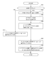
図11は、本発明の実施形態におけるGNSSアンテナの位置補正のフローチャートを示す。ステップ802において、後進フラグが立ったかどうか確認される。後進フラグが立ったときは、ステップ804において、目標の向首角(Ψpath)が算出される。ステップ806において、向首角の偏差(Ψerror=Ψpath-Ψm)が算出される。ステップ808において、アンテナ位置とトラクタのリヤアクスルの位置との距離(Wb)が決定される。ステップ810において、アンテナ位置での目標経路(ld)との横方向の偏差が決定される。ステップ812において、リヤアクスル位置での横方向の偏差(ld_rear axle)が決定される。
ステップ802において、後進フラグが立たない場合、ステップ814において、横方向の偏差は、アンテナ位置での目標経路(ld)との距離として決定される。
なお、後進制御に関する他の実施形態では、リヤアクスル位置での横方向の偏差を用いてラテラル制御を行うこともできる。 FIG. 11 shows a flowchart of position correction of the GNSS antenna in the embodiment of the present invention. Instep 802, it is checked whether the reverse flag is set. When the reverse flag is set, in step 804, the target head angle (Ψpath) is calculated. In step 806, the head angle deviation (Ψ error = Ψ path−Ψ m) is calculated. In step 808, the distance (Wb) between the antenna position and the position of the rear axle of the tractor is determined. In step 810, a lateral deviation from the target path (ld) at the antenna position is determined. In step 812, the lateral deviation (ld_rear axle) at the rear axle position is determined.
Instep 802, if the reverse flag is not raised, in step 814, the lateral deviation is determined as the distance from the target route (ld) at the antenna position.
In another embodiment relating to the reverse control, the lateral control can be performed using the lateral deviation at the rear axle position.
ステップ802において、後進フラグが立たない場合、ステップ814において、横方向の偏差は、アンテナ位置での目標経路(ld)との距離として決定される。
なお、後進制御に関する他の実施形態では、リヤアクスル位置での横方向の偏差を用いてラテラル制御を行うこともできる。 FIG. 11 shows a flowchart of position correction of the GNSS antenna in the embodiment of the present invention. In
In
In another embodiment relating to the reverse control, the lateral control can be performed using the lateral deviation at the rear axle position.
[別実施形態]
次に、図12から図16を参照して、[5.GNSSアンテナの位置補正]に関する別実施形態について説明する。本実施形態は、GNSSアンテナ50をトラクタ1の中央部又は後部に配置する例を示しており、GNSSアンテナ50をトラクタ1の前部に配置してない構成に関するものである。
図12は、GNSSアンテナ50をトラクタ1のキャビン5の前端に配置した例を示し、図16は、キャビンを有しないトラクタ60の後端のロールバー61にGNSSアンテナ50を配置した例を示す。 [Another embodiment]
Next, referring to FIGS. 12 to 16, [5. Another embodiment regarding position correction of the GNSS antenna] will be described. The present embodiment shows an example in which theGNSS antenna 50 is arranged at the center or rear part of the tractor 1 and relates to a configuration in which the GNSS antenna 50 is not arranged at the front part of the tractor 1.
FIG. 12 shows an example in which theGNSS antenna 50 is arranged at the front end of the cabin 5 of the tractor 1, and FIG. 16 shows an example in which the GNSS antenna 50 is arranged on the roll bar 61 at the rear end of the tractor 60 having no cabin.
次に、図12から図16を参照して、[5.GNSSアンテナの位置補正]に関する別実施形態について説明する。本実施形態は、GNSSアンテナ50をトラクタ1の中央部又は後部に配置する例を示しており、GNSSアンテナ50をトラクタ1の前部に配置してない構成に関するものである。
図12は、GNSSアンテナ50をトラクタ1のキャビン5の前端に配置した例を示し、図16は、キャビンを有しないトラクタ60の後端のロールバー61にGNSSアンテナ50を配置した例を示す。 [Another embodiment]
Next, referring to FIGS. 12 to 16, [5. Another embodiment regarding position correction of the GNSS antenna] will be described. The present embodiment shows an example in which the
FIG. 12 shows an example in which the
図12に示すように、GNSSアンテナ50は、トラクタ1のキャビン5の前端に配置されている。GNSSアンテナ50をキャビン5の上面に配置することにより、トラクタ1の振動をGNSSアンテナ50に伝達しにくいという効果を奏する。また、トラクタ1の最も高い位置にGNSSアンテナ50を配置することで、受信感度を向上できる。
As shown in FIG. 12, the GNSS antenna 50 is disposed at the front end of the cabin 5 of the tractor 1. By arranging the GNSS antenna 50 on the upper surface of the cabin 5, there is an effect that it is difficult to transmit the vibration of the tractor 1 to the GNSS antenna 50. Further, the reception sensitivity can be improved by arranging the GNSS antenna 50 at the highest position of the tractor 1.
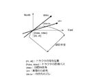
図13は、GNSSアンテナ位置の補正の様子を示す。本実施形態では、後進制御時に進行方向(後方)に仮想アンテナ位置を設定するだけでなく、前進制御時にも進行方向(前方)に仮想アンテナ位置を設定することで、アンテナ位置の補正を行い、ラテラル制御が行われる。
(1)前進制御
前進移動時は、GNSSアンテナ位置での横方向の偏差(L1)、及び、向首角の偏差(θ)に基づいて、GNSSアンテナからトラクタ前方に向けて所定距離(Wc)進めた位置での横方向の偏差(L3)を算出する。つまり、仮想アンテナ位置を進行方向に向けて進めた位置に配置して前進制御を行うことで、さらなる過渡応答の向上を図っている。
(2)後進制御
後進移動時は、GNSSアンテナ位置での横方向の偏差(L1)、及び、向首角の偏差(θ)に基づいて、GNSSアンテナからトラクタ後方に向けて所定距離(Wc)進めた位置での横方向の偏差(L3)を算出する。つまり、仮想アンテナ位置を進行方向に向けて進めた位置に配置して後進制御を行うことで、さらなる過渡応答の向上を図っている。 FIG. 13 shows how the GNSS antenna position is corrected. In the present embodiment, not only the virtual antenna position is set in the traveling direction (backward) during backward control, but also the antenna position is corrected by setting the virtual antenna position in the traveling direction (forward) during forward control, Lateral control is performed.
(1) Forward control During forward movement, a predetermined distance (Wc) from the GNSS antenna toward the front of the tractor based on the deviation (L1) in the lateral direction at the GNSS antenna position and the deviation (θ) in the head angle The lateral deviation (L3) at the advanced position is calculated. That is, the transient response is further improved by arranging the virtual antenna position at a position advanced in the traveling direction and performing forward control.
(2) Reverse control During reverse movement, a predetermined distance (Wc) from the GNSS antenna toward the rear of the tractor based on the deviation (L1) in the lateral direction at the GNSS antenna position and deviation (θ) in the head angle The lateral deviation (L3) at the advanced position is calculated. That is, the transient response is further improved by arranging the virtual antenna position at a position advanced in the traveling direction and performing the backward control.
図14は、本発明の別実施形態におけるGNSSアンテナの位置補正のフローチャートを示す。ステップ904において、目標の向首角(Ψpath)が算出される。ステップ906において、向首角の偏差(Ψerror=Ψpath-Ψm)が算出される。ステップ908において、アンテナ位置と仮想アンテナ位置との距離(Wc)が決定される。ステップ910において、アンテナ位置での目標パス(ld)との横方向の偏差が決定される。ステップ912において、仮想アンテナ位置での横方向の偏差(ld_virtual)が決定される。
以上のように、本実施形態では、前進制御と後進制御で同様のフローに従ってGNSSアンテナの位置補正が行われる。 FIG. 14 shows a flowchart of position correction of the GNSS antenna in another embodiment of the present invention. In step 904, a target head angle (Ψpath) is calculated. In step 906, the deviation of the head angle (Ψ error = Ψ path−Ψ m) is calculated. In step 908, the distance (Wc) between the antenna position and the virtual antenna position is determined. In step 910, a lateral deviation from the target path (ld) at the antenna position is determined. In step 912, the lateral deviation (ld_virtual) at the virtual antenna position is determined.
As described above, in this embodiment, the position correction of the GNSS antenna is performed according to the same flow in forward control and reverse control.
図15は、GNSSアンテナ位置の補正の様子を示す。本実施形態では、後進制御時に進行方向(後方)に仮想アンテナ位置を設定するだけでなく、前進制御時にも進行方向(前方)に仮想アンテナ位置を設定することで、アンテナ位置の補正を行い、ラテラル制御が行われる。
(1)前進制御
前進移動時は、GNSSアンテナ位置での横方向の偏差(L1)、及び、向首角の偏差(θ)に基づいて、GNSSアンテナからトラクタ前方に向けて所定距離(Wc)進めた位置での横方向の偏差(L3)を算出する。つまり、仮想アンテナ位置を進行方向に向けて進めた位置に配置して前進制御を行うことで、さらなる過渡応答の向上を図っている。
(2)後進制御
後進移動時は、GNSSアンテナ位置での横方向の偏差(L1)、及び、向首角の偏差(θ)に基づいて、GNSSアンテナからトラクタ後方に向けて所定距離(Wd)進めた位置での横方向の偏差(L4)を算出する。つまり、仮想アンテナ位置を進行方向に向けて進めた位置に配置して後進制御を行うことで、さらなる過渡応答の向上を図っている。
本実施形態では、前進制御時と後進制御時において進行方向に進める距離が異なっている。このように、前進制御と後進制御において、仮想アンテナの設置位置を変えることで、前進制御及び後進制御における最適な仮想アンテナ位置を設定することができ、横方向の偏差(L3、L4)を検出する感度を向上することができる。 FIG. 15 shows how the GNSS antenna position is corrected. In the present embodiment, not only the virtual antenna position is set in the traveling direction (backward) during backward control, but also the antenna position is corrected by setting the virtual antenna position in the traveling direction (forward) during forward control, Lateral control is performed.
(1) Forward control During forward movement, a predetermined distance (Wc) from the GNSS antenna toward the front of the tractor based on the deviation (L1) in the lateral direction at the GNSS antenna position and the deviation (θ) in the head angle The lateral deviation (L3) at the advanced position is calculated. That is, the transient response is further improved by arranging the virtual antenna position at a position advanced in the traveling direction and performing forward control.
(2) Reverse control During reverse movement, a predetermined distance (Wd) from the GNSS antenna toward the rear of the tractor based on the lateral deviation (L1) at the GNSS antenna position and the deviation (θ) in the head angle. The lateral deviation (L4) at the advanced position is calculated. That is, the transient response is further improved by arranging the virtual antenna position at a position advanced in the traveling direction and performing the backward control.
In the present embodiment, the distance advanced in the traveling direction is different between forward control and reverse control. Thus, by changing the virtual antenna installation position in forward control and reverse control, the optimal virtual antenna position in forward control and reverse control can be set, and lateral deviations (L3, L4) are detected. Sensitivity can be improved.
図16に示すように、自律走行車の一実施形態であるロボットトラクタ60は、キャビン5を有していない点でロボットトラクタ1と違っているが、その他は同様の構成を有する。そして、GNSSアンテナ50は、ロボットトラクタ60の後端に配置されるロールバー61の上面に配置される。また、受信アンテナ56は、例えばダッシュボード7に設けられる。
この場合も同様にGNSSアンテナの位置補正を行うことで、同様の作用効果を奏する。なお、ロボットトラクタ60において、GNSSアンテナ50は機体後方に配置されていることから、前進移動時にのみGNSSアンテナの位置補正を行う構成としても良い。つまり、前進制御において、仮想アンテナ位置を設置する一方で、後進制御においては、実際のアンテナ位置を用いて制御を行う構成としても良い。 As shown in FIG. 16, a robot tractor 60 that is an embodiment of an autonomous vehicle is different from therobot tractor 1 in that it does not have a cabin 5, but otherwise has the same configuration. The GNSS antenna 50 is disposed on the upper surface of the roll bar 61 disposed at the rear end of the robot tractor 60. The receiving antenna 56 is provided on the dashboard 7, for example.
In this case as well, the same effect can be obtained by correcting the position of the GNSS antenna. In the robot tractor 60, since theGNSS antenna 50 is disposed at the rear of the machine body, the position of the GNSS antenna may be corrected only during forward movement. In other words, the configuration may be such that the virtual antenna position is set in the forward control, while the control is performed using the actual antenna position in the reverse control.
この場合も同様にGNSSアンテナの位置補正を行うことで、同様の作用効果を奏する。なお、ロボットトラクタ60において、GNSSアンテナ50は機体後方に配置されていることから、前進移動時にのみGNSSアンテナの位置補正を行う構成としても良い。つまり、前進制御において、仮想アンテナ位置を設置する一方で、後進制御においては、実際のアンテナ位置を用いて制御を行う構成としても良い。 As shown in FIG. 16, a robot tractor 60 that is an embodiment of an autonomous vehicle is different from the
In this case as well, the same effect can be obtained by correcting the position of the GNSS antenna. In the robot tractor 60, since the
本発明は、予め決定された経路追従(種々の旋回を含む)における安定性を維持することで、例えば所定の位置精度範囲内の偏差制限内での自律走行車の誘導に含まれている課題を解決する。
The present invention includes, for example, the problem of guidance of an autonomous traveling vehicle within a deviation limit within a predetermined position accuracy range by maintaining stability in predetermined route following (including various turns). To solve.
従来技術では、誘導システムは、異なる誘導フェーズに対応しておらず、後進制御時のGNSSアンテナの位置補償を重視していなかったため、複合的な制御はなされていなかった。また、従来のラテラル制御は、ボディフレーム内のコマンドを算出していなかった。さらには、従来の概念では、トラクタ内にオペレータがいない状態での安定した自律作業を維持しつつ、異なった圃場サイズ及び形状に対して様々な自律作業を行うことはできなかった。
In the prior art, since the guidance system does not support different guidance phases and does not place importance on position compensation of the GNSS antenna at the time of reverse control, complex control has not been performed. Further, the conventional lateral control does not calculate a command in the body frame. Furthermore, in the conventional concept, it was not possible to perform various autonomous operations for different field sizes and shapes while maintaining a stable autonomous operation with no operator in the tractor.
本発明による技術思想は、ヘディング制御及び修正されたラテラル偏差制御を(並列で)行う複合制御をアウターループ制御で行い、ヨーレート制御をインナーループ制御で行うことである。本発明の制御設計では、ヨーレート制御は、操舵角よりも操舵角速度について行われる。より進化した制御設計によって、走行車の位置及び向首角の偏差を低減すること、並びに、地上の外乱が存在する中、土壌条件が異なる中、操舵システムの非線形性が存在する中でのシステムの安定性を維持することが可能である。
走行車の位置精度が高いレベルで求められることで、ロボットトラクタの制御を煩雑化している。そして、適切なゲインスケジューリング技術を伴う新たに設計された制御則によって、そのような煩雑さを解消し、所望の制約を実現できる。 The technical idea of the present invention is to perform combined control for performing heading control and modified lateral deviation control (in parallel) by outer loop control and performing yaw rate control by inner loop control. In the control design of the present invention, the yaw rate control is performed for the steering angular velocity rather than the steering angle. More advanced control design to reduce the position and head angle deviation of the traveling vehicle, and the system in the presence of ground disturbance, different soil conditions and the presence of nonlinear steering system It is possible to maintain the stability.
Since the position accuracy of the traveling vehicle is required at a high level, the control of the robot tractor is complicated. Then, a newly designed control law with an appropriate gain scheduling technique can eliminate such complexity and realize a desired constraint.
本発明では、誘導システムは、圃場における自律作業が静的パスに対する自律作業始動条件を満たすか否かを判別することで始動される。自律モードでは、静的パスの終点(耕作完了点)で停止することで、トラクタが圃場外に出ることを防止している。誘導システムは、圃場が異なるサイズ又は形状を有する場合にも様々な自律作業を行うことを可能にし、継続してトラクタの偏差を監視し、大きな偏差が生じた場合にトラクタを停止することで、安全性を確保している。
本発明では、トラクタ内にオペレータが常駐することが必要不可欠ではなく、それにより、ユーザーは、離れた位置でタブレット等の遠隔操作具を用いて自律作業を監視し、トラクタの速度を制限範囲内で変更し、ヒッチ作業を操作することができる。遠隔操作によりトラクタを停止した後、その停止位置から自律作業を再開することができる。 In the present invention, the guidance system is started by determining whether or not the autonomous work in the field satisfies the autonomous work start condition for the static path. In the autonomous mode, the tractor is prevented from going out of the field by stopping at the end point of the static path (cultivation completion point). The guidance system makes it possible to perform various autonomous work even when the field has different sizes or shapes, continuously monitoring the tractor deviation, and stopping the tractor when a large deviation occurs, Ensures safety.
In the present invention, it is not indispensable that an operator stays in the tractor, so that the user can monitor the autonomous work using a remote control device such as a tablet at a remote position and keep the speed of the tractor within a limited range. You can change and operate hitch work. After stopping the tractor by remote control, the autonomous work can be resumed from the stop position.
本実施形態で説明された誘導制御は、包括的なものであり、自律的な農作業に限定されることなく、自律的な乗用車等に適用することも可能である。
The guidance control described in this embodiment is comprehensive, and can be applied to autonomous passenger cars and the like without being limited to autonomous farming.
図面及び明細書に記載された事項と同等の関連性を有するものは、本発明に含まれるものである。本発明の実施形態に示されるものは例示であり、本発明の利用可能性を制限するものではない。当業者は、本発明から逸脱しない範囲で、具体的な実施形態に対する種々の修正及び代替について、開示された内容によって示唆される全ての範囲において改良することができる。
Those having the same relevance as the matters described in the drawings and specification are included in the present invention. What is shown in the embodiment of the present invention is an example, and does not limit the applicability of the present invention. Those skilled in the art can make various modifications and alternatives to the specific embodiments within the scope suggested by the disclosed contents without departing from the present invention.
自律走行車の誘導制御システム及び方法に関する本発明は、添付の図面に示された本発明の実施形態と関連させて説明されているが、これらに限定されることはない。すなわち、当業者による種々の代替、改良、変更は、本発明の範囲及び思想を逸脱しない範囲で誘導制御システムに対して適用可能である。
The present invention relating to a guidance control system and method for an autonomous vehicle has been described in connection with an embodiment of the present invention shown in the accompanying drawings, but is not limited thereto. That is, various alternatives, improvements, and changes by those skilled in the art can be applied to the guidance control system without departing from the scope and spirit of the present invention.
本発明は、自律走行車を目標経路に沿って走行させる誘導制御方法に利用可能である。
The present invention can be used in a guidance control method for causing an autonomous vehicle to travel along a target route.
1:ロボットトラクタ(自律走行車)、2:誘導制御システム、5:キャビン、21:作業機、50:GNSSアンテナ(衛星測位システムのアンテナ)、55:タブレット
1: Robot tractor (autonomous vehicle) 2: Guidance control system 5: Cabin 21: Work machine 50: GNSS antenna (satellite positioning system antenna) 55: Tablet
Claims (6)
- 衛星測位システムを利用して走行車の位置を測位しながら自律して走行及び作業を行う自律走行車の誘導制御システムであって、
前記自律走行車を後進移動させる際に、前記衛星測位システムのアンテナ位置よりも所定距離後方に仮想アンテナ位置を設定し、その仮想アンテナ位置における目標パスからの横方向の偏差を用いてラテラル制御を行うことを特徴とする自律走行車の誘導制御システム。 An autonomous traveling vehicle guidance control system that autonomously travels and works while positioning a traveling vehicle using a satellite positioning system,
When moving the autonomous vehicle backward, a virtual antenna position is set behind a predetermined distance from the antenna position of the satellite positioning system, and lateral control is performed using a lateral deviation from the target path at the virtual antenna position. A guidance control system for an autonomous vehicle characterized in that it performs. - 前記自律走行車の誘導制御システムは、
前記仮想アンテナ位置を選択しながら誘導制御信号を前記自律走行車に伝送するアンテナ位置補正モジュールと、
前記目標パスに基づいて前記自律走行車の走行を追跡するための誘導制御信号を生成する自律走行車走行モジュールと、
前記アンテナ位置補正モジュールと接続され、そのラテラル制御を行うラテラル制御モジュールと、
前記自律走行車走行モジュールと接続され、予測される向首角と実際の向首角との差を修正することで前記自律走行車の向首角のずれを制御するヘディング制御モジュールと、
前記ラテラル制御モジュール及びヘディング制御モジュールと接続され、ステアリング制御信号を生成するヨーレート制御モジュールと、を備える請求項1に記載の自律走行車の誘導制御システム。 The autonomous vehicle guidance control system includes:
An antenna position correction module that transmits a guidance control signal to the autonomous vehicle while selecting the virtual antenna position;
An autonomous vehicle traveling module that generates a guidance control signal for tracking the traveling of the autonomous vehicle based on the target path;
A lateral control module connected to the antenna position correction module and performing lateral control thereof;
A heading control module that is connected to the autonomous vehicle traveling module and controls a deviation of the head angle of the autonomous vehicle by correcting a difference between a predicted head angle and an actual head angle;
The autonomous control vehicle guidance control system according to claim 1, further comprising: a yaw rate control module that is connected to the lateral control module and the heading control module and generates a steering control signal. - 前記自律走行車の誘導制御システムは、前記自律走行車走行モジュールと接続され、前記目標パスに含まれる曲線経路の断続性に起因する前記目標パスからの偏差を修正するフィードフォワード制御モジュールをさらに備える請求項2に記載の自律走行車の誘導制御システム。 The guidance control system for an autonomous vehicle further includes a feedforward control module that is connected to the autonomous vehicle traveling module and corrects a deviation from the target path due to the intermittentness of a curved path included in the target path. The guidance control system for an autonomous vehicle according to claim 2.
- 前記自律走行車を前進移動させる際に、前記衛星測位システムのアンテナ位置よりも所定距離前方に仮想アンテナ位置を設定し、その仮想アンテナ位置における目標パスからの横方向の偏差を用いてラテラル制御を行う請求項1から3の何れか一項に記載の自律走行車の誘導制御システム。 When moving the autonomous vehicle forward, a virtual antenna position is set a predetermined distance ahead of the antenna position of the satellite positioning system, and lateral control is performed using a lateral deviation from the target path at the virtual antenna position. The guidance control system for an autonomous traveling vehicle according to any one of claims 1 to 3.
- 前記自律走行車は、目標パスからの横方向の偏差又は向首角の偏差が所定値を超えた場合に、停止され、自律走行を終了する請求項1から4の何れか一項に記載の自律走行車の誘導制御システム。 5. The autonomous traveling vehicle is stopped when the lateral deviation from the target path or the deviation of the head angle exceeds a predetermined value, and terminates autonomous traveling. 6. Guidance control system for autonomous vehicles.
- 前記自律走行車は、遠隔操作によるオーバーライド制御操作によって自律走行を停止可能であり、その停止位置から自律走行を再開可能である請求項1から5の何れか一項に記載の自律走行車の誘導制御システム。 The autonomous vehicle according to any one of claims 1 to 5, wherein the autonomous vehicle can stop autonomous driving by an override control operation by remote control and can restart autonomous driving from the stop position. Control system.
Priority Applications (2)
| Application Number | Priority Date | Filing Date | Title |
|---|---|---|---|
| JP2017516546A JP6437640B2 (en) | 2015-05-07 | 2015-12-07 | Guidance control system for autonomous vehicles |
| US15/805,644 US10761531B2 (en) | 2015-05-07 | 2017-11-07 | Guidance control system for autonomous-traveling vehicle |
Applications Claiming Priority (2)
| Application Number | Priority Date | Filing Date | Title |
|---|---|---|---|
| IN1824/MUM/2015 | 2015-05-07 | ||
| IN1824MU2015 IN2015MU01824A (en) | 2015-05-07 | 2015-12-07 |
Related Child Applications (1)
| Application Number | Title | Priority Date | Filing Date |
|---|---|---|---|
| US15/805,644 Continuation US10761531B2 (en) | 2015-05-07 | 2017-11-07 | Guidance control system for autonomous-traveling vehicle |
Publications (1)
| Publication Number | Publication Date |
|---|---|
| WO2016178294A1 true WO2016178294A1 (en) | 2016-11-10 |
Family
ID=54394908
Family Applications (1)
| Application Number | Title | Priority Date | Filing Date |
|---|---|---|---|
| PCT/JP2015/084338 WO2016178294A1 (en) | 2015-05-07 | 2015-12-07 | Induction control system for autonomous-traveling vehicle |
Country Status (4)
| Country | Link |
|---|---|
| US (1) | US10761531B2 (en) |
| JP (2) | JP6437640B2 (en) |
| IN (1) | IN2015MU01824A (en) |
| WO (1) | WO2016178294A1 (en) |
Cited By (16)
| Publication number | Priority date | Publication date | Assignee | Title |
|---|---|---|---|---|
| CN106323270A (en) * | 2016-07-29 | 2017-01-11 | 北京合众思壮科技股份有限公司 | Data collection method and device |
| JP2018120364A (en) * | 2017-01-24 | 2018-08-02 | 株式会社クボタ | Automatic steering system |
| CN108808240A (en) * | 2018-07-25 | 2018-11-13 | 安徽泗州拖拉机制造有限公司 | A kind of large size driverless tractor antenna |
| CN109936976A (en) * | 2017-01-24 | 2019-06-25 | 株式会社久保田 | Combine harvester, harvester and automatic steering system |
| JP2019108008A (en) * | 2017-12-18 | 2019-07-04 | 株式会社クボタ | Tractor |
| EP3514651A1 (en) * | 2018-01-17 | 2019-07-24 | AGCO International GmbH | Steering controller for autonomous vehicle with stability regulation |
| JP2019168939A (en) * | 2018-03-23 | 2019-10-03 | ヤンマー株式会社 | Autonomous travel system |
| JP2020012678A (en) * | 2018-07-13 | 2020-01-23 | 株式会社クボタ | Work machine |
| WO2020016677A1 (en) * | 2018-07-18 | 2020-01-23 | Precision Planting Llc | Systems and methods of working a field and determining a location of implements within a field |
| WO2020105125A1 (en) * | 2018-11-20 | 2020-05-28 | 本田技研工業株式会社 | Autonomous work machine, autonomous work machine control method, and program |
| JP2020528846A (en) * | 2017-10-26 | 2020-10-01 | エスゼット ディージェイアイ テクノロジー カンパニー リミテッドSz Dji Technology Co.,Ltd | Agricultural machinery control methods, equipment and systems |
| JP2021013382A (en) * | 2020-10-14 | 2021-02-12 | 株式会社クボタ | Working vehicle |
| JP2021083403A (en) * | 2019-11-29 | 2021-06-03 | 株式会社クボタ | Work vehicle |
| JP2021107179A (en) * | 2019-12-27 | 2021-07-29 | 本田技研工業株式会社 | Vehicle controller, vehicle, and method for controlling vehicle |
| US11383703B2 (en) | 2017-01-20 | 2022-07-12 | Kubota Corporation | Work vehicle |
| JP2023004371A (en) * | 2021-06-25 | 2023-01-17 | 井関農機株式会社 | work vehicle |
Families Citing this family (20)
| Publication number | Priority date | Publication date | Assignee | Title |
|---|---|---|---|---|
| US10589971B2 (en) * | 2016-12-15 | 2020-03-17 | Richard Arnold | Working platform for a tractor |
| US10742494B2 (en) * | 2017-04-27 | 2020-08-11 | Veoneer Us, Inc. | System and method for configuring at least one sensor system of a vehicle |
| DE202017103847U1 (en) * | 2017-06-28 | 2017-07-21 | Airbus Operations Gmbh | System for guiding a robot through a passenger aircraft cabin |
| US10671070B2 (en) * | 2018-05-23 | 2020-06-02 | Baidu Usa Llc | PID embedded LQR for autonomous driving vehicles (ADVS) |
| CA3107440A1 (en) | 2018-09-14 | 2020-03-19 | Agjunction Llc | Using non-real-time computers for agricultural guidance systems |
| EP3887863A1 (en) * | 2018-12-02 | 2021-10-06 | MTD Products Inc | Autonomous mower navigation system and method |
| CN109765886B (en) * | 2018-12-21 | 2022-05-24 | 北京智行者科技有限公司 | Target track identification method followed by vehicle |
| US11324158B2 (en) * | 2019-01-25 | 2022-05-10 | Deere & Company | System and method for controlling an implement connected to a vehicle |
| CN110109452A (en) * | 2019-04-11 | 2019-08-09 | 湖南龙舟农机股份有限公司 | A kind of double antenna navigation border protection systems |
| GB2585222B (en) * | 2019-07-03 | 2022-10-12 | Raytheon Systems Ltd | Autonomous vehicles supporting global navigation satellite system (gnss) anti-spoofing |
| EP4002980B1 (en) * | 2019-07-26 | 2023-06-21 | AgJunction LLC | Using smart-phones and other hand-held mobile devices in precision agriculture |
| EP4028844A2 (en) | 2019-09-09 | 2022-07-20 | Mtd Products Inc. | Real time kinematics power equipment device with auto-steering |
| US11377112B2 (en) * | 2019-11-13 | 2022-07-05 | Baidu Usa Llc | Low-speed, backward driving vehicle controller design |
| JP7262374B2 (en) * | 2019-11-20 | 2023-04-21 | ヤンマーパワーテクノロジー株式会社 | Automated driving system for work vehicles |
| WO2021115371A1 (en) * | 2019-12-13 | 2021-06-17 | 苏州宝时得电动工具有限公司 | Working map construction method and apparatus, robot, and storage medium |
| US11531115B2 (en) * | 2020-02-12 | 2022-12-20 | Caterpillar Global Mining Llc | System and method for detecting tracking problems |
| US11685412B2 (en) * | 2020-03-05 | 2023-06-27 | Caterpillar Paving Products Inc. | Override of autonomous functions of a machine |
| CN111487976B (en) * | 2020-05-03 | 2022-11-18 | 哈尔滨工程大学 | Backing track tracking method |
| US20220128993A1 (en) * | 2020-10-23 | 2022-04-28 | Deere & Company | Methods, apparatus, and articles of manufacture to display acquisition paths |
| US20230048365A1 (en) * | 2021-08-11 | 2023-02-16 | Here Global B.V. | Corrected trajectory mapping |
Citations (3)
| Publication number | Priority date | Publication date | Assignee | Title |
|---|---|---|---|---|
| JPH05333928A (en) * | 1992-05-29 | 1993-12-17 | Meidensha Corp | Back traveling control method for unmanned carrier |
| JPH0713619A (en) * | 1993-06-25 | 1995-01-17 | Kubota Corp | Automatic traveling vehicle |
| JP2002358122A (en) * | 2001-05-31 | 2002-12-13 | Yanmar Agricult Equip Co Ltd | Agricultural work vehicle |
Family Cites Families (13)
| Publication number | Priority date | Publication date | Assignee | Title |
|---|---|---|---|---|
| DE19830858A1 (en) * | 1998-07-10 | 2000-01-13 | Claas Selbstfahr Erntemasch | Device and method for determining a virtual position |
| US6756887B2 (en) * | 2001-07-23 | 2004-06-29 | Wayne W. Evans | Method and apparatus for the dynamic vector control of automatic variable range and directional reception of gps global positioning signals, dynamic vehicle tracking, remote notification of collision and synthetic voice data communications |
| US7400956B1 (en) * | 2003-03-20 | 2008-07-15 | Hemisphere Gps Inc. | Satellite position and heading sensor for vehicle steering control |
| US9002565B2 (en) * | 2003-03-20 | 2015-04-07 | Agjunction Llc | GNSS and optical guidance and machine control |
| US7127340B2 (en) * | 2004-08-17 | 2006-10-24 | Deere & Company | Variable gain logic for a GPS based automatic steering system |
| JP4948098B2 (en) * | 2006-09-12 | 2012-06-06 | ヤンマー株式会社 | Agricultural work vehicle |
| US8803735B2 (en) * | 2010-11-19 | 2014-08-12 | Agjunction Llc | Portable base station network for local differential GNSS corrections |
| DE102011114183A1 (en) * | 2011-09-22 | 2013-03-28 | Bomag Gmbh | Method for controlling a loading process of a transport vehicle with milled material, device for carrying out such a method and milling device |
| US20140168009A1 (en) * | 2012-12-17 | 2014-06-19 | Trimble Navigation Ltd. | Multi-IMU INS for vehicle control |
| CA2921137C (en) * | 2013-09-10 | 2017-08-15 | Agco Corporation | Combo crop harvester crop transfer means |
| EP3104244B1 (en) * | 2014-02-06 | 2019-03-27 | Yanmar Co., Ltd. | Parallel travel work system |
| CN105980948B (en) * | 2014-02-06 | 2019-12-31 | 洋马株式会社 | Method for setting travel route of autonomous travel work vehicle |
| WO2016017367A1 (en) * | 2014-07-30 | 2016-02-04 | ヤンマー株式会社 | Remote control apparatus |
-
2015
- 2015-12-07 WO PCT/JP2015/084338 patent/WO2016178294A1/en active Application Filing
- 2015-12-07 JP JP2017516546A patent/JP6437640B2/en active Active
- 2015-12-07 IN IN1824MU2015 patent/IN2015MU01824A/en unknown
-
2017
- 2017-11-07 US US15/805,644 patent/US10761531B2/en active Active
-
2018
- 2018-11-14 JP JP2018214230A patent/JP2019061695A/en active Pending
Patent Citations (3)
| Publication number | Priority date | Publication date | Assignee | Title |
|---|---|---|---|---|
| JPH05333928A (en) * | 1992-05-29 | 1993-12-17 | Meidensha Corp | Back traveling control method for unmanned carrier |
| JPH0713619A (en) * | 1993-06-25 | 1995-01-17 | Kubota Corp | Automatic traveling vehicle |
| JP2002358122A (en) * | 2001-05-31 | 2002-12-13 | Yanmar Agricult Equip Co Ltd | Agricultural work vehicle |
Cited By (27)
| Publication number | Priority date | Publication date | Assignee | Title |
|---|---|---|---|---|
| CN106323270A (en) * | 2016-07-29 | 2017-01-11 | 北京合众思壮科技股份有限公司 | Data collection method and device |
| US11904851B2 (en) | 2017-01-20 | 2024-02-20 | Kubota Corporation | Work vehicle |
| US11383703B2 (en) | 2017-01-20 | 2022-07-12 | Kubota Corporation | Work vehicle |
| JP6994831B2 (en) | 2017-01-24 | 2022-01-14 | 株式会社クボタ | Automatic steering system |
| JP2018120364A (en) * | 2017-01-24 | 2018-08-02 | 株式会社クボタ | Automatic steering system |
| KR20190104311A (en) * | 2017-01-24 | 2019-09-09 | 가부시끼 가이샤 구보다 | Combine harvesters, harvesters, and automatic steering systems |
| CN109936976A (en) * | 2017-01-24 | 2019-06-25 | 株式会社久保田 | Combine harvester, harvester and automatic steering system |
| KR102539520B1 (en) * | 2017-01-24 | 2023-06-05 | 가부시끼 가이샤 구보다 | Combines, Harvesters, and Autopilot Systems |
| JP2020528846A (en) * | 2017-10-26 | 2020-10-01 | エスゼット ディージェイアイ テクノロジー カンパニー リミテッドSz Dji Technology Co.,Ltd | Agricultural machinery control methods, equipment and systems |
| JP2019108008A (en) * | 2017-12-18 | 2019-07-04 | 株式会社クボタ | Tractor |
| EP3514651A1 (en) * | 2018-01-17 | 2019-07-24 | AGCO International GmbH | Steering controller for autonomous vehicle with stability regulation |
| US11029690B2 (en) | 2018-01-17 | 2021-06-08 | Agco International Gmbh | Steering controller for an autonomous vehicle with stability regulation |
| JP2019168939A (en) * | 2018-03-23 | 2019-10-03 | ヤンマー株式会社 | Autonomous travel system |
| JP2020012678A (en) * | 2018-07-13 | 2020-01-23 | 株式会社クボタ | Work machine |
| CN112203496A (en) * | 2018-07-18 | 2021-01-08 | 精密种植有限责任公司 | System and method for working in a field and determining a position of an implement within the field |
| WO2020016677A1 (en) * | 2018-07-18 | 2020-01-23 | Precision Planting Llc | Systems and methods of working a field and determining a location of implements within a field |
| CN108808240A (en) * | 2018-07-25 | 2018-11-13 | 安徽泗州拖拉机制造有限公司 | A kind of large size driverless tractor antenna |
| WO2020105125A1 (en) * | 2018-11-20 | 2020-05-28 | 本田技研工業株式会社 | Autonomous work machine, autonomous work machine control method, and program |
| JPWO2020105125A1 (en) * | 2018-11-20 | 2021-09-27 | 本田技研工業株式会社 | Autonomous work machine, control method and program of autonomous work machine |
| JP7201704B2 (en) | 2018-11-20 | 2023-01-10 | 本田技研工業株式会社 | AUTONOMOUS WORKING MACHINE, CONTROL METHOD AND PROGRAM FOR AUTONOMOUS WORKING MACHINE |
| JP2021083403A (en) * | 2019-11-29 | 2021-06-03 | 株式会社クボタ | Work vehicle |
| JP7183141B2 (en) | 2019-11-29 | 2022-12-05 | 株式会社クボタ | work vehicle |
| JP2021107179A (en) * | 2019-12-27 | 2021-07-29 | 本田技研工業株式会社 | Vehicle controller, vehicle, and method for controlling vehicle |
| JP7094338B2 (en) | 2020-10-14 | 2022-07-01 | 株式会社クボタ | Work vehicle |
| JP2021013382A (en) * | 2020-10-14 | 2021-02-12 | 株式会社クボタ | Working vehicle |
| JP2023004371A (en) * | 2021-06-25 | 2023-01-17 | 井関農機株式会社 | work vehicle |
| JP7392689B2 (en) | 2021-06-25 | 2023-12-06 | 井関農機株式会社 | work vehicle |
Also Published As
| Publication number | Publication date |
|---|---|
| JP2019061695A (en) | 2019-04-18 |
| JPWO2016178294A1 (en) | 2018-03-01 |
| US20180321682A1 (en) | 2018-11-08 |
| JP6437640B2 (en) | 2018-12-12 |
| US10761531B2 (en) | 2020-09-01 |
| IN2015MU01824A (en) | 2015-05-22 |
Similar Documents
| Publication | Publication Date | Title |
|---|---|---|
| JP6437640B2 (en) | Guidance control system for autonomous vehicles | |
| US10732637B2 (en) | Apparatus and method for controlling a vehicle | |
| CN109154817B (en) | Automatic traveling work vehicle | |
| US10401856B2 (en) | Vehicle travel control apparatus | |
| US11052943B2 (en) | System and method for controlling a vehicle | |
| CN107943049B (en) | Unmanned vehicle control method and unmanned mowing vehicle | |
| US11180189B2 (en) | Automated reverse implement parking | |
| US9526199B2 (en) | Work vehicle coordinating system | |
| JP6420173B2 (en) | Automated traveling field work vehicle | |
| US11167792B2 (en) | Single-mode implement steering | |
| US20180011495A1 (en) | Route search method, route search system, non-transitory computer-readable storage medium, and work vehicle | |
| CN107943060B (en) | Autopilot, method for guiding a vehicle along a tracking line, and computer-readable medium | |
| US8818568B2 (en) | Satellite-based automatic steering system | |
| Iida et al. | Path-following control of a head-feeding combine robot | |
| JP7083445B2 (en) | Autonomous driving system | |
| JP2019038535A (en) | Automatic travel field work vehicle | |
| JP2005247008A (en) | Control device for unmanned helicopter | |
| JP4939170B2 (en) | Tracking system | |
| JP6695297B2 (en) | Autonomous driving system | |
| US20220151134A1 (en) | Automatic Travel System | |
| JP2019053470A (en) | Work vehicle-purpose autonomous travelling system | |
| US20220163971A1 (en) | Robotic vehicle with safety measures | |
| JP7000283B2 (en) | Vehicle driving control device | |
| JP2019053471A (en) | Work vehicle-purpose autonomous travelling system | |
| JP2023110557A (en) | automatic steering system |
Legal Events
| Date | Code | Title | Description |
|---|---|---|---|
| 121 | Ep: the epo has been informed by wipo that ep was designated in this application |
Ref document number: 15891301 Country of ref document: EP Kind code of ref document: A1 |
|
| ENP | Entry into the national phase |
Ref document number: 2017516546 Country of ref document: JP Kind code of ref document: A |
|
| NENP | Non-entry into the national phase |
Ref country code: DE |
|
| 122 | Ep: pct application non-entry in european phase |
Ref document number: 15891301 Country of ref document: EP Kind code of ref document: A1 |