WO2016175087A1 - Soundproof cover of compressor for air conditioner - Google Patents
Soundproof cover of compressor for air conditioner Download PDFInfo
- Publication number
- WO2016175087A1 WO2016175087A1 PCT/JP2016/062374 JP2016062374W WO2016175087A1 WO 2016175087 A1 WO2016175087 A1 WO 2016175087A1 JP 2016062374 W JP2016062374 W JP 2016062374W WO 2016175087 A1 WO2016175087 A1 WO 2016175087A1
- Authority
- WO
- WIPO (PCT)
- Prior art keywords
- compressor
- sound
- soundproof cover
- main body
- insulating material
- Prior art date
Links
Images


Classifications
-
- F—MECHANICAL ENGINEERING; LIGHTING; HEATING; WEAPONS; BLASTING
- F04—POSITIVE - DISPLACEMENT MACHINES FOR LIQUIDS; PUMPS FOR LIQUIDS OR ELASTIC FLUIDS
- F04B—POSITIVE-DISPLACEMENT MACHINES FOR LIQUIDS; PUMPS
- F04B39/00—Component parts, details, or accessories, of pumps or pumping systems specially adapted for elastic fluids, not otherwise provided for in, or of interest apart from, groups F04B25/00 - F04B37/00
- F04B39/0027—Pulsation and noise damping means
- F04B39/0033—Pulsation and noise damping means with encapsulations
-
- F—MECHANICAL ENGINEERING; LIGHTING; HEATING; WEAPONS; BLASTING
- F24—HEATING; RANGES; VENTILATING
- F24F—AIR-CONDITIONING; AIR-HUMIDIFICATION; VENTILATION; USE OF AIR CURRENTS FOR SCREENING
- F24F1/00—Room units for air-conditioning, e.g. separate or self-contained units or units receiving primary air from a central station
- F24F1/06—Separate outdoor units, e.g. outdoor unit to be linked to a separate room comprising a compressor and a heat exchanger
- F24F1/08—Compressors specially adapted for separate outdoor units
- F24F1/12—Vibration or noise prevention thereof
-
- G—PHYSICS
- G10—MUSICAL INSTRUMENTS; ACOUSTICS
- G10K—SOUND-PRODUCING DEVICES; METHODS OR DEVICES FOR PROTECTING AGAINST, OR FOR DAMPING, NOISE OR OTHER ACOUSTIC WAVES IN GENERAL; ACOUSTICS NOT OTHERWISE PROVIDED FOR
- G10K11/00—Methods or devices for transmitting, conducting or directing sound in general; Methods or devices for protecting against, or for damping, noise or other acoustic waves in general
- G10K11/16—Methods or devices for protecting against, or for damping, noise or other acoustic waves in general
- G10K11/162—Selection of materials
- G10K11/168—Plural layers of different materials, e.g. sandwiches
Definitions
- the present invention relates to a soundproof cover of a compressor for an air conditioner provided in an outdoor unit of an air conditioner.
- Patent Document 1 discloses that a felt material molded on the outer surface of a compressor of an outdoor unit is attached, and an aluminum plate is attached to the outer surface of the felt material to be used as a soundproof material.
- Patent Document 1 uses a hard material such as an aluminum plate, there is a risk that solid propagation sound may be generated when it interferes with surrounding parts due to vibration generated during operation of the compressor. For this reason, when actually using the soundproof material of patent document 1, it is necessary to provide another shock absorbing material.
- the present invention has been made in view of such circumstances, and an object thereof is to provide a soundproof cover for a compressor for an air conditioner having excellent soundproofing performance and having manufacturability and workability. .
- the soundproof cover of the compressor for an air conditioner according to the present invention has a shape corresponding to the outer shape of the compressor main body including the compressor leg located on the lower end side, and is formed of rubber or thermoplastic elastomer having sound insulation properties.
- a sound-insulating material main body that covers the compressor main body by being bent through the bent portion, and having a bent portion along the height direction of the compressor main body.
- a sound insulating material head which is a molded product of rubber or thermoplastic elastomer having sound insulating properties, having a shape corresponding to the outer shape of the compressor head located on the upper end side, and provided at least inside the sound insulating material main body. And a sound absorbing material.
- the soundproof cover of the compressor for an air conditioner according to the present invention can have manufacturability and workability while having excellent soundproof performance.
- the external appearance block diagram of the soundproof cover of the compressor for air conditioners in this embodiment The external appearance block diagram at the time of unfolding the soundproof cover of FIG.
- the internal block diagram at the time of unfolding the soundproof cover of FIG. The longitudinal cross-sectional view at the time of attaching a soundproof cover to a compressor. Sectional drawing along the thickness direction of the soundproof cover. Sectional drawing which shows the 1st modification of the soundproof cover in this embodiment.
- the external appearance perspective view which shows the 2nd modification of the soundproof cover in this embodiment. Sectional drawing of the 2nd modification in case a sound-insulating material bottom part is a sheet metal.
- the external appearance block diagram which shows the 3rd modification of the soundproof cover in this embodiment.
- Sectional drawing which expanded the slit part of the soundproof cover is an external view of the soundproof cover according to the first embodiment, (b) is a plan view of the soundproof cover of FIG. 12 (a), and (c) is a cross-sectional view taken along the line CC of FIG. 12 (b).
- (A) is an external view explaining the evaluation point of an acoustic vibration test,
- (b) is a plan view of FIG. 13 (a).
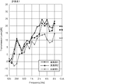
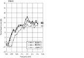
- the graph which shows the sound pressure level difference accompanying the presence or absence of the soundproof cover in the evaluation point 1 which concerns on Example 1, Example 2, and the comparative example 1.
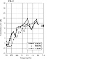
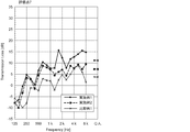
- FIG. 1 The graph which shows the sound pressure level difference accompanying the presence or absence of the soundproof cover in the evaluation point 2 which concerns on Example 1, Example 2, and the comparative example 1.
- FIG. 3 which concerns on Example 1, Example 2, and the comparative example 1.
- FIG. 4 The graph which shows the sound pressure level difference accompanying the presence or absence of the soundproof cover in the evaluation point 4 which concerns on Example 1, Example 2, and the comparative example 1.
- FIG. 5 The graph which shows the sound pressure level difference accompanying the presence or absence of the soundproof cover in the evaluation point 5 which concerns on Example 1, Example 2, and the comparative example 1.
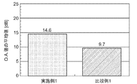
- FIG. 22 is a graph comparing the average values of transmission loss overall values at the respective evaluation points of Example 1 and Comparative Example 1 shown in FIGS.
- FIG. 22 is a graph comparing average values of transmission loss overall values at the respective evaluation points of Example 1 and Example 2 shown in FIGS.
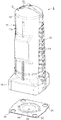
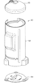
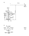
- FIG. 1 is an external configuration diagram of a soundproof cover 1 of a compressor for an air conditioner according to the present embodiment.
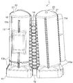
- FIG. 2 is an external configuration diagram when the soundproof cover 1 of FIG. 1 is developed.
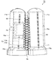
- FIG. 3 is an internal configuration diagram when the soundproof cover 1 of FIG. 1 is developed.
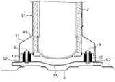
- FIG. 4 is a longitudinal sectional view when the soundproof cover 1 is attached to the compressor 2.
- the soundproof cover 1 of the compressor for an air conditioner in the present embodiment is attached to the compressor 2 in order to prevent sound (vibration) generated from, for example, the compressor 2 provided in the outdoor unit of the air conditioner. Used.
- the compressor 2 includes a compressor main body 3 and a dome-shaped compressor head 5 positioned on the upper end side of the compressor main body 3.
- the compressor body 3 has a compressor leg 6 that is the lower end of the compressor body 3.
- the compressor leg 6 is a base of the compressor 2 projecting outward from the lower end of the compressor main body 3, and fixes the compressor 2 to the bottom frame 8 of the outdoor unit in which the compressor 2 is installed.
- the compressor 2 is fixed to the bottom frame 8 using bolts 9 at a plurality of locations (four locations in the present embodiment) via the compressor legs 6.
- a vibration isolating rubber 10 is installed for the purpose of isolating the bolt 9, the compressor leg 6 and the bottom frame 8.
- the soundproof cover (soundproof cover) 1 of the compressor for an air conditioner includes a sound insulation material main body 11, a sound insulation material head 21, a sound insulation material bottom 31, and a sound absorption material 41 (see FIG. 3). ).
- the sound insulating material main body 11 has a shape corresponding to the outer shape of the compressor main body 3.
- the sound insulating material main body 11 has a concavo-convex shape corresponding to the shape of pipes or protrusions provided in the compressor 2.
- the lower end side 15 of the sound insulating material main body 11 has a shape corresponding to the outer shape of the compressor leg 6. That is, the sound insulating material main body 11 includes a portion corresponding to the compressor leg 6.
- the sound insulating material main body 11 has a bent portion 12 along the height direction of the soundproof cover 1.
- the sound insulating material main body 11 covers the compressor main body 3 by being bent through the bent portion 12.
- the sound insulating material main body 11 is divided into two members 11a and 11b (see FIG. 2) at a cut surface along the height direction passing through the substantially central axis of the soundproof cover 1, and these two members. 11 a and 11 b are connected via the bent portion 12.
- One member 11 a of the sound insulating material main body 11 is provided with a fixing portion 13 a that overlaps and fixes the other member 11 b when the soundproof cover 1 is attached to the compressor 2.
- the fixing portion 13a is fixed to a fixed portion 13b provided on the member 11b by a fixing method such as a hook-and-loop fastener.
- the fixing portion 13a and the fixed portion 13b are provided from the upper end side 16 to the lower end side 15 of the sound insulating material main body portion 11.
- the bent portion 12 includes a rib 14 provided in a direction substantially perpendicular to the bending direction of the bent portion 12.
- the ribs 14 are provided in three rows at a plurality of locations at regular intervals along the bending direction so that unnecessary bending does not occur in the vicinity of the bending portion 12 when the soundproof cover 1 is attached to the compressor 2.
- the sound insulating material head 21 has a shape corresponding to the outer shape of the compressor head 5.
- the sound insulating material head 21 is formed integrally with the sound insulating material main body 11. That is, the sound insulating material head 21 is formed continuously from the upper end side 16 of the sound insulating material main body 11.
- the sound insulating material head 21 is provided with a pipe through hole 22 through which a pipe provided in the compressor head 5 passes.
- the sound insulating material bottom 31 has a shape for covering the compressor leg 6 (compressor 2) from below (from the bottom of the compressor 2). Specifically, as shown in FIG. 4, the sound insulating material bottom 31 is provided between the compressor leg 6 and the bottom frame 8 of the air conditioner. When the sound insulating material bottom 31 is attached to the compressor 2, the sound insulating material bottom 31 does not come into contact with the compressor bottom 7. This is because the sound insulating material bottom 31 may be damaged by the vibration of the compressor 2.
- the sound insulating material bottom 31 is provided with bolt through holes 32 through which the bolts 9 for fixing the compressor 2 to the bottom frame 8 pass according to the number of the bolts 9.
- the sound insulating material bottom 31 has a drain hole 33 for discharging moisture that has entered the inside of the soundproof cover 1 to the outside of the soundproof cover 1. Furthermore, the sound insulating material bottom 31 has reinforcing ribs 34 for increasing the strength of the sound insulating material bottom 31.
- the sound insulating material main body 11 comes into contact with the peripheral edge 35 of the sound insulating material bottom 31. This is to reduce the aperture ratio as much as possible in order not to leak the sound generated from the compressor 2 to the outside.
- the sound insulating material body 11, the sound insulating material head 21, and the sound insulating material bottom 31 are molded products of rubber or thermoplastic elastomer having sound insulating properties.
- the sound insulating materials 11, 21, and 31 are preferably polyolefin thermoplastic elastomer (Thermo Plastic Olefin, TPO) molded products.
- the sound insulating material bottom 31 may be an iron press-formed product, a flat cut product (a flat cut product that is not formed), or a hot press-formed product of a nonwoven fabric and a felt sheet.
- the sound insulating materials 11, 21, 31 and the sound absorbing material 41 are formed as separate bodies and forming the sound insulating materials 11, 21, 31 from rubber or thermoplastic elastomer, it is possible to perform molding that sufficiently follows the shape of the compressor 2. Become.
- the sound insulating materials 11, 21, and 31 preferably have a thickness of 1 to 4 mm. The thickness may be uniform or locally changed.
- the sound absorbing material 41 is provided at least inside the sound insulating material main body 11.
- the sound absorbing material 41 is fixed to the inside of the sound insulating material main body 11 by a resin fixing pin (so-called tag pin) used when a tag (price tag) is attached, or is fixed by an adhesive material.
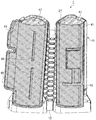
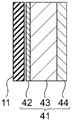
- FIG. 5 is a cross-sectional view of the soundproof cover 1 along the thickness direction.
- a nonwoven fabric sheet 42, a flame retardant felt sheet 43, and an aluminum sheet 44 are arranged in this order from the sound insulating material main body 11 side.
- the flame retardant felt sheet 43 is a felt sheet mainly composed of natural fiber, chemical fiber (synthetic fiber, regenerated fiber, low melting point chemical fiber, etc.), glass wool, glass formed by needle punching.
- a fiber aggregate such as a felt sheet made of fibers or a laminate thereof, a polyurethane foam having open cells (including a soft polyurethane foam and a hard polyurethane foam), and the like can be used.
- the felt sheet 43 is preferably a resin felt having flame retardancy.
- the nonwoven fabric sheet 42 is a nonwoven fabric having appropriate air permeability that does not impair the sound absorption of the felt sheet 43.
- the nonwoven fabric sheet 42 is formed of polyester fiber, low melting point polyester fiber, polypropylene fiber, polyethylene fiber, polyamide fiber, acrylic fiber, urethane fiber, polyvinyl chloride fiber, glass fiber, or the like.
- This nonwoven fabric sheet 42 has flame retardancy.
- the non-woven fabric sheet 42 is made of an organic flame retardant (bromine compound, phosphorus compound, chlorine compound), an inorganic flame retardant (antimony compound, metal hydroxide), and a difficult flame as disclosed in JP-A-2006-83505. By applying and impregnating the flammable material, the required flame retardancy can be provided.
- the flame retardancy is imparted, for example, by applying and impregnating a nonwoven fabric with a thermosetting resorcinol resin composed of monovalent and polyhydric phenols, and then thermosetting. Moreover, a flame retardance can be provided also by containing a flame-retardant fiber.
- the nonwoven fabric sheet 42 contains a thermosetting resin such as a resorcinol resin. Thereby, it shape
- the nonwoven fabric sheet 42 further has oil repellency and water repellency. Oil repellency and water repellency are imparted by further impregnating the nonwoven fabric sheet 42 with a fluorine-based water and oil repellent.
- the nonwoven fabric sheet 42 is bonded to at least the peripheral portions 45 of the nonwoven fabric sheet 42 and the aluminum sheet 44 by the thermosetting resin described above (see FIG. 3). When the thermosetting resin has insufficient adhesiveness due to manufacturing conditions or the like, an adhesive such as a hot melt adhesive is applied.
- the adhesive is polyethylene, polypropylene, polyolefin resin, polyvinyl chloride, polyurethane, polyester, polyamide, phenol resin, epoxy resin, and the like, and these containing solutions are coated and impregnated on the nonwoven fabric.
- an aluminum glass cloth (Aluminum-Laminated Glass-Cloth, ALGC), which is a sheet obtained by bonding a glass fiber cloth to an aluminum foil, can be used.
- ALGC Alignment-Laminated Glass-Cloth
- a polyethylene layer is laminated on the inner surface of the aluminum sheet 44 from the viewpoint of heat adhesion with the nonwoven fabric sheet 42 at the peripheral edge 45. When heated, the polyethylene layer melts, reacts with the resin or hot melt adhesive on the nonwoven fabric sheet 42 side, and the nonwoven fabric sheet 42 and the aluminum sheet 44 are bonded.
- the aluminum sheet 44 a sheet in which an aluminum foil, a polyethylene layer, a cloth, and a polyethylene layer are sequentially laminated can be used.
- the sound absorbing material 41 made of each member is integrally formed with the nonwoven sheet 42 and the aluminum sheet 44 covering the felt sheet 43.
- positioned inside when it installs in the compressor 2 of the sound-absorbing material 41 is the circumferential direction compared with the surface (surface on the nonwoven fabric sheet 42 side) arrange
- the felt sheet 43 is composed of a plurality of sheets arranged with gaps 46 (see FIG. 3) at predetermined positions in order to absorb the difference in circumferential length.
- the structure of the sound absorbing material 41 in the present embodiment is an example, and is not limited to this as long as the entire soundproof cover 1 has sound absorbing performance in relation to the sound insulating materials 11, 21, and 31.
- the sound absorbing material may be provided with a sound absorbing material head 47 inside the sound insulating material head 21.
- the sound-absorbing material head 47 may be a sound-absorbing material consisting only of a felt sheet, or may have the same configuration as the sound-absorbing material 41 described above.
- the integrated sound insulating material main body 11 and sound insulating material head 21 are manufactured by vacuum forming and simultaneous trimming (simultaneous trim type vacuum forming) using the above-described materials.
- the sound insulating material main body 11 and the sound insulating material head 21 are produced by injection molding.
- the sound insulating material bottom 31 is produced by injection molding or press molding using the above-described materials.
- the sound absorbing material 41 is hot press-molded in a state where a nonwoven fabric sheet 42, a flame retardant felt sheet 43, and an aluminum sheet 44 are laminated.
- the peripheral edge 45 is bonded by the action of the thermosetting resin or hot melt adhesive contained in the nonwoven fabric sheet 42, the polyethylene layer provided on the aluminum sheet 44, or the like.
- the felt sheet 43 is disposed on the inner side of the peripheral edge 45 to be heat-pressed, and the sound absorbing material 41 can be immediately formed integrally. Further, the gap 46 between the felt sheets 43 is also hot pressed to bond the aluminum sheet 44 and the nonwoven fabric sheet 42 together.
- the sound absorbing material 41 is fixed to the sound insulating materials 11, 21, 31 by tag pins or the like. Thereby, the soundproof cover 1 is manufactured.
- the soundproof cover 1 (the sound insulating material main body 11 and the sound insulating material head 21 to which the sound absorbing material 41 is fixed) is attached to the compressor 2 along the outer shape of the compressor 2. Since the soundproof cover 1 is divided into two members 11 a and 11 b via the bent portion 12, the soundproof cover 1 is mounted so as to be wound around the outer periphery of the compressor 2.
- the two members 11a and 11b are fixed via the fixing portion 13a and the fixed portion 13b.
- the members 11a and 11b are connected by, for example, male and female hook-and-loop fasteners provided on the members 11a and 11b, respectively.
- the soundproof cover 1 in this embodiment can realize the soundproof cover 1 having the smallest possible aperture ratio by disposing a molded product having a shape corresponding to the outer shape of the compressor 2 in the outermost layer. It can. That is, the sound insulating materials 11, 21, and 31 having a shape corresponding to the outer shape of the compressor 2 are arranged on the outside, and the sound absorbing material 41 having a suitable thickness is further arranged on the inside. Thereby, the airtight structure of the soundproof cover 1 and the compressor 2 can be formed, and an aperture ratio can be reduced. Further, the integrated sound insulating materials 11 and 21 can further contribute to the reduction of the aperture ratio. Thereby, the sound generated from the compressor 2 can be absorbed and attenuated inside the soundproof cover 1, and the sound can be efficiently prevented.
- the sound insulating material main body 11 and the sound insulating material head 21 are integrally formed, the mounting can be performed at a time, and the number of work steps can be reduced. Further, at the time of mounting, unlike a conventional molded product that is mounted over the compressor 2 (see, for example, Patent Document 1), it is wound around the compressor 2 and mounted. For this reason, the soundproof cover 1 of this embodiment does not require a space on the compressor 2, and if the required space is ensured around the compressor 2 side surface, it is easily attached.
- the soundproof cover 1 is formed of a flexible material such as rubber or thermoplastic elastomer, it is necessary to transport the soundproof cover 1 in a state where it is attached to the compressor 2 as in the conventional molded product, that is, in a cylindrical shape. It can be folded and transported as needed. Moreover, compared with the case where the sound insulating material main body 11 and the sound insulating material head 21 are configured as separate members, the overlapping portion can be omitted, and the amount of material used can be reduced.
- the soundproof cover 1 since the soundproof cover 1 has the peripheral portion 35 of the sound insulation material bottom portion 31 in contact with the sound insulation material main body portion 11 to improve the sealing, the possibility of sound leakage from below the sound insulation cover 1 is also reduced. can do. Moreover, since the sound insulating materials 11, 21, and 31 of the outermost layer are materials having flexibility, it is possible to reduce solid propagation sound due to interference with surrounding parts. As a result, no additional cushioning material for solid sound propagation with surrounding components is required.
- the flexibility of the soundproof cover 1 can improve workability regardless of the position of the pipe connected to the compressor 2.
- the above-described conventional molded product that is mounted over the compressor 2 can be used only for a pipe that extends from above.
- the soundproof cover 1 in the present embodiment can perform operations such as maintenance of the compressor 2 in a state where only the lower end side 15 is fixed by the fixing portion 13a and the fixed portion 13b and only the upper side is opened. .
- a further reinforcing plate may be added between the compressor 2 and the bottom frame 8 for the purpose of reinforcing the bottom frame 8 to which the weight of the compressor 2 is added.
- the reinforcing plate may be omitted by having the sound insulating material bottom 31 also function as a reinforcing plate.
- FIG. 6 is a cross-sectional view showing a first modification of the soundproof cover 1 in the present embodiment.
- the sound insulating material bottom 55 also functions as a sheet metal that is a reinforcing plate.
- the sound insulating material main body 11 has a lower end 52 having a shape in contact with the sound insulating material bottom 55. That is, since the lower end 52 is in contact with the sound insulating material bottom 55, even if the sound insulating material bottom 55 also serves as a reinforcing plate, the sealing degree of the sound insulating cover 51 can be maintained in the same manner.
- a soundproof sheet having soundproofness such as a felt sheet may be further disposed on the sound insulating material bottom 55. Thereby, the soundproof performance can be further improved.
- the sound insulating material bottom 55 may be omitted. In this case, the bottom frame 8 and the lower end 52 are in contact with each other, so that the sealing degree can be maintained.
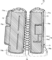
- FIG. 7 is an external perspective view showing a second modification of the soundproof cover 1 in the present embodiment.
- FIG. 8 is a cross-sectional view of a second modification in the case where the sound insulating material bottom is a sheet metal.
- the sound insulation cover 61 is provided with a sound insulation material main body 62, a sound insulation material head 63, and a sound insulation material bottom (not shown in FIG. 7) as separate bodies.
- the sound insulating material head 63 has an overlapping portion with the sound insulating material main body 62, and is fixed to the sound insulating material main body 62 by a hook-and-loop fastener or the like at this overlapping portion.
- the soundproof cover 61 has a sound absorbing material 65 (see FIG. 8) at least inside the sound insulating material main body 62. Even with such a soundproof cover 61, a soundproof cover with a high degree of sealing (small aperture ratio) can be realized as with the soundproof cover 1 described above.
- the sound insulating material bottom is formed of iron sheet metal, a flat sound insulating material bottom 64a can be used as shown in FIG. Even in this case, the sound insulating material main body 62 is in contact with the peripheral edge 66 of the sound insulating material bottom 64a. Since the other structure of the soundproof cover 61 is substantially the same as that of the soundproof cover 1, detailed description thereof is omitted.
- the sound insulating material main body 11 and the sound absorbing material 41 are divided in the middle of the upper end and the lower end of the sound insulating material main body 11, and partially with respect to the compressor 2. It may be possible to fix to.
- FIG. 9 is an external configuration diagram showing a third modification of the soundproof cover 1 in the present embodiment.
- FIG. 10 is a configuration diagram of the inside of the soundproof cover 70 of FIG.
- FIG. 11 is an enlarged partial cross-sectional view of the slit portion of the soundproof cover 70.
- a one-dot chain line 73a in FIG. 11 indicates the position of the slit 73a.
- An alternate long and short dash line 74a indicates the position of the slit 74a.
- Configurations and parts corresponding to those in the above embodiment are denoted by the same reference numerals, and redundant description is omitted.
- a soundproof cover 70 as a third modified example has slits 73 and 74 in the sound insulating material main body 71 and the sound absorbing material 72. 9 and 10, the slits 73 and 74 are indicated by dotted lines for convenience of explanation.
- the slit 73 (sound insulation material slit) of the sound insulation material main body 71 is provided in the height direction of the fixed portion 75a and the fixed portion 76a, the fixed portion 75b, and the fixed portion 76b for fixing the members 71a and 71b at the time of mounting. It is provided near the boundary.
- the slit 73 is perpendicular to the slit 73 a along the circumferential direction of the member 71 b provided with the fixed portions 76 a and 76 b and the convex portion 79 corresponding to the terminal box of the compressor 2 from the slit 73 a.
- an elongated slit 73b One end of the slit 73a is positioned at the circumferential end of the member 71b (on the fixed portion 76a). The other end of the slit 73a is positioned in front of the bent portion 78.
- the slit 74 (sound absorbing material slit) of the sound absorbing material 72 is provided at a position different from the slit 73 of the sound insulating material main body 71 in the height direction.
- the slit 74 is provided at a position higher than the slit 73.
- the slit 74 includes a slit 74a along the circumferential direction of the sound absorbing material 72 disposed inside the member 71b, and a slit 74b extending in the orthogonal direction from the slit 74a to a position corresponding to the convex portion 79.
- One end of the slit 74 a is located at one end in the circumferential direction of the sound absorbing material 72.
- the other end of the slit 74 a is positioned in front of the other end in the circumferential direction of the sound absorbing material 72.
- the sound insulation material main body 71 reduces the rigidity.
- the sound insulating material main body 71 has the reinforcing ribs 80, it is possible to ensure the rigidity and the self-supporting property of the soundproof cover 70.
- the slit 73a moisture such as rainwater may enter the soundproof cover 70, corroding the felt sheet and the like, which may cause the compressor 2 to corrode and leak.
- the sound insulating material main body 71 is provided with the convex portion 81 along the slit 73 a above the slit 73 a, and therefore can prevent moisture from entering from the slit 73 a.
- the soundproof cover 70 as the third modified example can be partially attached. That is, only the lower part than the slit 73 of the sound insulating material main body 71 covering the compressor leg 6 is fixed by the fixing part 75b and the fixed part 76b, and the compressor 2 is exposed above the slit 73. be able to. For this reason, wiring work of a terminal box or the like can be performed while the soundproof cover 70 is partially attached. For example, it is useful when the soundproof cover 70 is attached or when the compressor 2 is maintained. Moreover, a pipe
- the positions of the slits 73 and 74 are preferably determined according to the wiring work position of the compressor 2 and the like. For this reason, you may provide only the slit along a circumferential direction.
- the slits 73 and 74 may be provided on the member 71a side (fixed portions 75a and 75b side).
- the positions of the slit 73 and the slit 74 were made different in the height direction. As a result, sound leakage from the gap that occurs when the slit positions of the sound insulating material main body 71 and the sound absorbing material 72 overlap can be eliminated, and the soundproofing performance can be enhanced as much as possible.
- FIG. 12A is an external view of the soundproof cover 100 according to the first embodiment
- FIG. 12B is a plan view of the soundproof cover 100 in FIG. 12A
- FIG. 12C is a CC line in FIG. It is sectional drawing which follows.
- the soundproof cover 100 according to the first embodiment includes a sound insulating material head 101, a sound insulating material main body 103, a sound insulating material bottom 105, a sound absorbing material head 102, and a sound absorbing material main body 104.
- the sound insulating material head 101 and the sound insulating material main body 103 are made of a TPO-based molded product.
- the sound insulating material bottom 105 is formed by sandwiching a felt sheet from both sides with a non-woven sheet and hot press molding with a mold.
- the nonwoven fabric sheet is a spunbonded nonwoven fabric impregnated with a thermosetting resin.
- the felt sheet is a thermosetting resin felt.
- the sound absorbing material head 102 is made of needle felt.
- a nonwoven fabric sheet, a felt sheet, and an aluminum sheet are arranged in this order from the sound insulating material main body 103 side.
- the nonwoven fabric sheet is a spunbonded nonwoven fabric impregnated with a thermosetting resin.
- the felt sheet is a thermosetting resin felt.
- the aluminum sheet is ALGC. Table 1 shows the surface weight and thickness of each member.
- the soundproof cover of the second embodiment is the same as the soundproof cover 100 of the first embodiment except that the soundproof material bottom 105 is not provided.
- the soundproof cover of Comparative Example 1 has a sound insulating material head and a sound absorbing material main body.
- the sound insulating material head is the same as the sound insulating material head 101 of the first embodiment.
- the sound-absorbing material main body is formed by stacking two sound-absorbing materials.
- One sound-absorbing material arranged on the outer side is a member in which a vinyl chloride sheet, a felt sheet, a vinyl chloride sheet, a felt sheet, and an aluminum sheet are combined in order from the outside.
- the other sound absorbing material disposed inside is a member in which a vinyl chloride sheet, a felt sheet, and an aluminum sheet are combined in order from the outside.
- the felt sheet is needle felt, and the aluminum sheet is aluminum foil.
- the aluminum sheet and the felt sheet are attached with an adhesive material or the like.
- the vinyl chloride sheet and the felt sheet are fixed with tag pins. Table 1 shows the surface weight and thickness of each member.
- Example 1 In order to evaluate the sound insulation and soundproofing performance of Examples 1 and 2 and Comparative Example 1, an acoustic excitation test was performed in a completely anechoic chamber (volume 30 m 3 , background noise 20 dB (A) or less, cutting frequency 140 Hz, sound absorption rate 98%). Went. The acoustic vibration test was performed by evaluating the difference in sound pressure level obtained with and without the soundproof cover as performance.
- acoustic excitation was performed with a speaker from within the jig.
- the speaker installation position as the excitation position was a 125 mm position (excitation point 1), a 250 mm position (excitation point 2), and a 375 mm position (excitation point 3) from the simulation compressor installation surface.
- the microphone installation position as the evaluation position is the center position (evaluation point 1) above the compressor (soundproof cover), the lower end position 110 of the sound insulation material (evaluation point 2), the terminal box position 111, and the simulation.
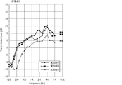
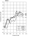
- FIG. 14 to FIG. 21 are graphs showing the sound pressure level difference according to the presence or absence of the soundproof cover at the evaluation points 1 to 8 according to Example 1, Example 2 and Comparative Example 1. 14 to 21, the horizontal axis indicates the frequency (Hz), and the vertical axis indicates the sound pressure level difference (dB) with or without the soundproof cover.
- FIG. 22 is a graph comparing the average values of transmission loss overall values (O.A. values) at the respective evaluation points of Example 1 and Comparative Example 1 shown in FIGS. FIG.
- FIGS. 14 to 23 is a graph comparing the average values of transmission loss overall values (O.A. values) at the respective evaluation points of Example 1 and Example 2 shown in FIGS.
- a value smaller than 0 dB may appear for the convenience of the measuring instrument.
- FIGS. 14 to 23 are graphs showing the difference in sound pressure level with or without the soundproof cover as a soundproof effect (how much the sound pressure level has been lowered). The larger the value, the greater the soundproof effect.
- Example 1 and Example 2 are comparative example 1. It was found that the soundproofing performance was higher than that. When evaluated by the O.A. value, the performance of Example 1 was improved by about 5 dB compared to Comparative Example 1. Also, depending on the frequency band, Example 1 and Example 2 achieved a performance improvement of 10 dB or more compared to Comparative Example 1.
- Example 1 when comparing the soundproofing performance with and without the bottom of the sound insulating material by comparing Example 1 and Example 2, Example 1 realized an improvement in the performance of an OA value of about 2 dB relative to Example 2. . Moreover, according to the evaluation at each evaluation point, it was found that the performance is improved particularly at a high frequency of 1 KHz or more by providing the sound insulating cover with the bottom of the sound insulating material. This is because the soundproof performance can be greatly improved by sealing the bottom of the compressor.
Abstract
[Problem] To provide the soundproof cover of a compressor for an air conditioner that is easy to manufacture and operate while also having excellent soundproofing performance. [Solution] This soundproof cover is provided with: a sound-insulating material main body section (11) that is a sound-insulating rubber or thermoplastic elastomer molded product having a shape corresponding to the outer shape of a compressor main body section that includes a compressor leg section positioned on the lower-end side, the sound-insulating material main body section (11) having a folding part (12) that extends along the height direction of the compressor main body section, and covering the compressor main body by being folded via the folding part (12); a sound-insulating material head section (21) which has a shape corresponding to the outer shape of a compressor head section positioned on the upper-end side of the compressor main body section, and which is a sound-insulating rubber or thermoplastic elastomer molded product; and a sound-absorbing member provided at least to the inner side of the sound-insulating material main body section (11).
Description
本発明は、空調機の室外機などに設けられた空気調和機用圧縮機の防音カバーに関する。
The present invention relates to a soundproof cover of a compressor for an air conditioner provided in an outdoor unit of an air conditioner.
従来、例えば空気調和装置の室外機内部に収容される圧縮機には、この圧縮機から発せられる運転音が外部に漏れることを抑制する目的で、種々の防音手段が設けられる。例えば、特許文献1には室外機の圧縮機外面に成形加工されたフェルト材を装着し、さらにフェルト材の外面にアルミニウム板を貼り付けることにより防音材として用いることが開示されている。
Conventionally, for example, a compressor housed inside an outdoor unit of an air conditioner is provided with various soundproofing means for the purpose of suppressing leakage of operation sound emitted from the compressor to the outside. For example, Patent Document 1 discloses that a felt material molded on the outer surface of a compressor of an outdoor unit is attached, and an aluminum plate is attached to the outer surface of the felt material to be used as a soundproof material.
しかし、特許文献1の防音材は、アルミニウム板という硬い素材を用いるため、圧縮機の運転時に発生する振動により、周囲部品と干渉した際に固体伝播音が発生する恐れがある。このため、特許文献1の防音材を実際に使用する場合には、他の緩衝材を設ける必要がある。
However, since the soundproofing material of Patent Document 1 uses a hard material such as an aluminum plate, there is a risk that solid propagation sound may be generated when it interferes with surrounding parts due to vibration generated during operation of the compressor. For this reason, when actually using the soundproof material of patent document 1, it is necessary to provide another shock absorbing material.
本発明はこのような事情を考慮してなされたもので、優れた防音性能を有しつつ、製造性、作業性を備えた空気調和機用圧縮機の防音カバーを提供することを目的とする。
The present invention has been made in view of such circumstances, and an object thereof is to provide a soundproof cover for a compressor for an air conditioner having excellent soundproofing performance and having manufacturability and workability. .
本発明に係る空気調和機用圧縮機の防音カバーは、下端側に位置する圧縮機脚部を含む圧縮機本体部の外形に対応する形状を有する、遮音性を有するゴムまたは熱可塑性エラストマーの成形品であり、前記圧縮機本体部の高さ方向に沿った折り曲げ部を有し、前記折り曲げ部を介して折り曲げられることにより前記圧縮機本体を覆う遮音材本体部と、前記圧縮機本体部の上端側に位置する圧縮機頭部の外形に対応する形状を有する、遮音性を有するゴムまたは熱可塑性エラストマーの成形品である遮音材頭部と、少なくとも前記遮音材本体部の内側に設けられた吸音材と、を備えたことを特徴とする。
The soundproof cover of the compressor for an air conditioner according to the present invention has a shape corresponding to the outer shape of the compressor main body including the compressor leg located on the lower end side, and is formed of rubber or thermoplastic elastomer having sound insulation properties. A sound-insulating material main body that covers the compressor main body by being bent through the bent portion, and having a bent portion along the height direction of the compressor main body. A sound insulating material head, which is a molded product of rubber or thermoplastic elastomer having sound insulating properties, having a shape corresponding to the outer shape of the compressor head located on the upper end side, and provided at least inside the sound insulating material main body. And a sound absorbing material.
本発明に係る空気調和機用圧縮機の防音カバーにおいては、優れた防音性能を有しつつ、製造性、作業性を備えることができる。
The soundproof cover of the compressor for an air conditioner according to the present invention can have manufacturability and workability while having excellent soundproof performance.
本発明に係る空気調和機用圧縮機の防音カバーの一実施形態を添付図面に基づいて説明する。
An embodiment of a soundproof cover for an air conditioner compressor according to the present invention will be described with reference to the accompanying drawings.
図1は、本実施形態における空気調和機用圧縮機の防音カバー1の外観構成図である。
図2は、図1の防音カバー1を展開した場合の外観構成図である。
図3は、図1の防音カバー1を展開した場合の内側の構成図である。
図4は、防音カバー1を圧縮機2に装着した場合の縦断面図である。 FIG. 1 is an external configuration diagram of asoundproof cover 1 of a compressor for an air conditioner according to the present embodiment.
FIG. 2 is an external configuration diagram when thesoundproof cover 1 of FIG. 1 is developed.
FIG. 3 is an internal configuration diagram when thesoundproof cover 1 of FIG. 1 is developed.
FIG. 4 is a longitudinal sectional view when thesoundproof cover 1 is attached to the compressor 2.
図2は、図1の防音カバー1を展開した場合の外観構成図である。
図3は、図1の防音カバー1を展開した場合の内側の構成図である。
図4は、防音カバー1を圧縮機2に装着した場合の縦断面図である。 FIG. 1 is an external configuration diagram of a
FIG. 2 is an external configuration diagram when the
FIG. 3 is an internal configuration diagram when the
FIG. 4 is a longitudinal sectional view when the
本実施形態における空気調和機用圧縮機の防音カバー1は、例えば空調機の室外機に設けられる圧縮機2から生ずる音(振動)を防音(防振)するために、圧縮機2に装着されて使用される。
The soundproof cover 1 of the compressor for an air conditioner in the present embodiment is attached to the compressor 2 in order to prevent sound (vibration) generated from, for example, the compressor 2 provided in the outdoor unit of the air conditioner. Used.
図4に示すように、圧縮機2は、圧縮機本体部3と、圧縮機本体部3の上端側に位置するドーム型の圧縮機頭部5とを備える。圧縮機本体部3は、圧縮機本体部3の下端部である圧縮機脚部6を有する。圧縮機脚部6は、圧縮機本体部3の下端部から外側に張り出した圧縮機2の土台であり、圧縮機2が設置された室外機の底フレーム8に対して圧縮機2を固定する部分である。圧縮機2は、圧縮機脚部6を介して、複数箇所(本実施形態においては4箇所)において底フレーム8に対してボルト9を用いて固定される。ボルト9、圧縮機脚部6および底フレーム8の防振を目的として、防振ゴム10が設置される。
As shown in FIG. 4, the compressor 2 includes a compressor main body 3 and a dome-shaped compressor head 5 positioned on the upper end side of the compressor main body 3. The compressor body 3 has a compressor leg 6 that is the lower end of the compressor body 3. The compressor leg 6 is a base of the compressor 2 projecting outward from the lower end of the compressor main body 3, and fixes the compressor 2 to the bottom frame 8 of the outdoor unit in which the compressor 2 is installed. Part. The compressor 2 is fixed to the bottom frame 8 using bolts 9 at a plurality of locations (four locations in the present embodiment) via the compressor legs 6. A vibration isolating rubber 10 is installed for the purpose of isolating the bolt 9, the compressor leg 6 and the bottom frame 8.
図1に示すように、空気調和機用圧縮機の防音カバー(防音カバー)1は、遮音材本体部11と、遮音材頭部21と、遮音材底部31と、吸音材41(図3参照)とを備える。
As shown in FIG. 1, the soundproof cover (soundproof cover) 1 of the compressor for an air conditioner includes a sound insulation material main body 11, a sound insulation material head 21, a sound insulation material bottom 31, and a sound absorption material 41 (see FIG. 3). ).
遮音材本体部11は、圧縮機本体部3の外形に対応する形状を有する。すなわち、遮音材本体部11は、圧縮機2に設けられた配管や突起物などの形状に対応した凹凸形状を有する。また、遮音材本体部11の下端側15は、圧縮機脚部6の外形にも対応する形状を有する。すなわち、遮音材本体部11には、圧縮機脚部6に対応する部分も含まれる。遮音材本体部11は、防音カバー1の高さ方向に沿った折り曲げ部12を有する。遮音材本体部11は、折り曲げ部12を介して折り曲げられることにより圧縮機本体部3を覆う。具体的には、遮音材本体部11は、防音カバー1の略中心軸を通る高さ方向に沿う切断面で2つの部材11a、11b(図2参照)に分割されており、この2つの部材11a、11bが折り曲げ部12を介して接続されている。遮音材本体部11の一方の部材11aには、防音カバー1を圧縮機2に装着した際に他方の部材11bと重なり合い互いに固定するための固定部13aが設けられる。固定部13aは、例えば面ファスナーなどの固定方法で部材11bに設けられた被固定部13bに固定される。なお、固定部13aおよび被固定部13bは、遮音材本体部11の上端側16から下端側15にかけて設けられる。また、部材11aおよび部材11bの遮音材頭部21の重なり合いも、面ファスナーなどにより固定される。折り曲げ部12は、折り曲げ部12の折り曲げ方向に対して略垂直方向に設けられたリブ14を有する。リブ14は、防音カバー1を圧縮機2に装着した場合に折り曲げ部12近傍に不要なたわみが発生しないように、折り曲げ方向に沿って一定間隔で複数箇所に、3列に亘って設けられる。
The sound insulating material main body 11 has a shape corresponding to the outer shape of the compressor main body 3. In other words, the sound insulating material main body 11 has a concavo-convex shape corresponding to the shape of pipes or protrusions provided in the compressor 2. Further, the lower end side 15 of the sound insulating material main body 11 has a shape corresponding to the outer shape of the compressor leg 6. That is, the sound insulating material main body 11 includes a portion corresponding to the compressor leg 6. The sound insulating material main body 11 has a bent portion 12 along the height direction of the soundproof cover 1. The sound insulating material main body 11 covers the compressor main body 3 by being bent through the bent portion 12. Specifically, the sound insulating material main body 11 is divided into two members 11a and 11b (see FIG. 2) at a cut surface along the height direction passing through the substantially central axis of the soundproof cover 1, and these two members. 11 a and 11 b are connected via the bent portion 12. One member 11 a of the sound insulating material main body 11 is provided with a fixing portion 13 a that overlaps and fixes the other member 11 b when the soundproof cover 1 is attached to the compressor 2. The fixing portion 13a is fixed to a fixed portion 13b provided on the member 11b by a fixing method such as a hook-and-loop fastener. The fixing portion 13a and the fixed portion 13b are provided from the upper end side 16 to the lower end side 15 of the sound insulating material main body portion 11. Further, the overlap of the sound insulating material head 21 of the member 11a and the member 11b is also fixed by a hook-and-loop fastener or the like. The bent portion 12 includes a rib 14 provided in a direction substantially perpendicular to the bending direction of the bent portion 12. The ribs 14 are provided in three rows at a plurality of locations at regular intervals along the bending direction so that unnecessary bending does not occur in the vicinity of the bending portion 12 when the soundproof cover 1 is attached to the compressor 2.
図1または図2に示すように、遮音材頭部21は、圧縮機頭部5の外形に対応する形状を有する。遮音材頭部21は、遮音材本体部11と一体に成形されたものである。すなわち、遮音材頭部21は、遮音材本体部11の上端側16から連続して成形されたものである。遮音材頭部21は、圧縮機頭部5に設けられた配管が貫通するための配管貫通孔22が設けられる。
As shown in FIG. 1 or FIG. 2, the sound insulating material head 21 has a shape corresponding to the outer shape of the compressor head 5. The sound insulating material head 21 is formed integrally with the sound insulating material main body 11. That is, the sound insulating material head 21 is formed continuously from the upper end side 16 of the sound insulating material main body 11. The sound insulating material head 21 is provided with a pipe through hole 22 through which a pipe provided in the compressor head 5 passes.
遮音材底部31は、圧縮機脚部6(圧縮機2)を下方から(圧縮機2の底部から)覆うための形状を有する。具体的には、図4に示すように、遮音材底部31は、圧縮機脚部6と、空調機の底フレーム8との間に設けられる。遮音材底部31が圧縮機2に装着された際、遮音材底部31は圧縮機底部7に接触しないようになっている。圧縮機2の振動により遮音材底部31が破損する恐れがあるためである。遮音材底部31は、圧縮機2を底フレーム8に固定するためのボルト9が貫通するボルト貫通孔32が、ボルト9の本数に応じて設けられる。また、遮音材底部31は、防音カバー1内部に浸入した水分を防音カバー1外部に排出するための水抜き穴33を有する。さらに、遮音材底部31は、遮音材底部31の強度を増すための補強用リブ34を有する。遮音材底部31が配置された場合、遮音材本体部11は、遮音材底部31の周縁部35と接するようになっている。圧縮機2から生じる音を外部に漏らさないため開口率を可能な限り小さくするためである。
The sound insulating material bottom 31 has a shape for covering the compressor leg 6 (compressor 2) from below (from the bottom of the compressor 2). Specifically, as shown in FIG. 4, the sound insulating material bottom 31 is provided between the compressor leg 6 and the bottom frame 8 of the air conditioner. When the sound insulating material bottom 31 is attached to the compressor 2, the sound insulating material bottom 31 does not come into contact with the compressor bottom 7. This is because the sound insulating material bottom 31 may be damaged by the vibration of the compressor 2. The sound insulating material bottom 31 is provided with bolt through holes 32 through which the bolts 9 for fixing the compressor 2 to the bottom frame 8 pass according to the number of the bolts 9. In addition, the sound insulating material bottom 31 has a drain hole 33 for discharging moisture that has entered the inside of the soundproof cover 1 to the outside of the soundproof cover 1. Furthermore, the sound insulating material bottom 31 has reinforcing ribs 34 for increasing the strength of the sound insulating material bottom 31. When the sound insulating material bottom 31 is disposed, the sound insulating material main body 11 comes into contact with the peripheral edge 35 of the sound insulating material bottom 31. This is to reduce the aperture ratio as much as possible in order not to leak the sound generated from the compressor 2 to the outside.
遮音材本体部11、遮音材頭部21および遮音材底部31(遮音材11、21、31)は、それぞれ遮音性を有するゴムまたは熱可塑性エラストマーの成形品である。遮音材11、21、31は、ポリオレフィン系熱可塑性エラストマー(Thermo Plastic Olefin、TPO)系の成形品であることが好ましい。また、遮音材底部31は、鉄製のプレス成形品、平裁断品(成形されていない平形状の裁断品)、不織布とフェルトシートとの熱プレス成形品でもよい。遮音材11、21、31と吸音材41とを別体とし、遮音材11、21、31をゴムまたは熱可塑性エラストマーで形成することにより、圧縮機2の形状に十分に追従した成形が可能となる。遮音材11、21、31は1~4mmの厚みを有するのが好ましい。厚みは、均一であってもよいし、局部的に変更させてもよい。
The sound insulating material body 11, the sound insulating material head 21, and the sound insulating material bottom 31 (sound insulating materials 11, 21, 31) are molded products of rubber or thermoplastic elastomer having sound insulating properties. The sound insulating materials 11, 21, and 31 are preferably polyolefin thermoplastic elastomer (Thermo Plastic Olefin, TPO) molded products. The sound insulating material bottom 31 may be an iron press-formed product, a flat cut product (a flat cut product that is not formed), or a hot press-formed product of a nonwoven fabric and a felt sheet. By forming the sound insulating materials 11, 21, 31 and the sound absorbing material 41 as separate bodies and forming the sound insulating materials 11, 21, 31 from rubber or thermoplastic elastomer, it is possible to perform molding that sufficiently follows the shape of the compressor 2. Become. The sound insulating materials 11, 21, and 31 preferably have a thickness of 1 to 4 mm. The thickness may be uniform or locally changed.
吸音材41は、少なくとも遮音材本体部11の内側に設けられる。吸音材41は、遮音材本体部11の内側に対して、タグ(値札)を取り付ける際に使用される樹脂製の固定ピン(いわゆるタグピン)により固定されたり、粘着材により固定されたりする。図5は、防音カバー1の厚さ方向に沿った断面図である。吸音材41には、遮音材本体部11側から順に、不織布シート42、難燃性フェルトシート43、アルミシート44が配置される。
The sound absorbing material 41 is provided at least inside the sound insulating material main body 11. The sound absorbing material 41 is fixed to the inside of the sound insulating material main body 11 by a resin fixing pin (so-called tag pin) used when a tag (price tag) is attached, or is fixed by an adhesive material. FIG. 5 is a cross-sectional view of the soundproof cover 1 along the thickness direction. In the sound absorbing material 41, a nonwoven fabric sheet 42, a flame retardant felt sheet 43, and an aluminum sheet 44 are arranged in this order from the sound insulating material main body 11 side.
難燃性フェルトシート43(フェルトシート43)は、天然繊維、化学繊維(合成繊維、再生繊維、低融点化学繊維など)などを主成分とするフェルトシート、グラスウール、ニードルパンチ加工で成形された硝子繊維からなるフェルトシート、またはそれらの積層物などの繊維集合体、連続気泡を有するポリウレタン発泡体(軟質ポリウレタン発泡体、硬質ポリウレタン発泡体を含む)などを用いることができる。フェルトシート43は、難燃性を有するレジンフェルトであることが好ましい。
The flame retardant felt sheet 43 (felt sheet 43) is a felt sheet mainly composed of natural fiber, chemical fiber (synthetic fiber, regenerated fiber, low melting point chemical fiber, etc.), glass wool, glass formed by needle punching. A fiber aggregate such as a felt sheet made of fibers or a laminate thereof, a polyurethane foam having open cells (including a soft polyurethane foam and a hard polyurethane foam), and the like can be used. The felt sheet 43 is preferably a resin felt having flame retardancy.
不織布シート42は、フェルトシート43の吸音性を損なわない適度の通気性を有する不織布である。不織布シート42は、ポリエステル繊維、低融点ポリエステル繊維、ポリプロピレン繊維、ポリエチレン繊維、ポリアミド繊維、アクリル繊維、ウレタン繊維、ポリ塩化ビニル繊維、ガラス繊維などで形成される。この不織布シート42は、難燃性を有する。不織布シート42は、有機系難燃材(臭素化合物、リン化合物、塩素化合物)、無機系難燃材(アンチモン化合物、金属水酸化物)および特開2006-83505号公報に開示されたような難燃性材料が塗布含浸されることにより、所要の難燃性を備えることができる。難燃性は、例えば1価および多価フェノールからなる熱硬化性のレゾルシノール系樹脂などを不織布に塗布含浸させ、熱硬化することにより付与される。また、難燃性は、難燃性繊維を含有することによっても付与することができる。
The nonwoven fabric sheet 42 is a nonwoven fabric having appropriate air permeability that does not impair the sound absorption of the felt sheet 43. The nonwoven fabric sheet 42 is formed of polyester fiber, low melting point polyester fiber, polypropylene fiber, polyethylene fiber, polyamide fiber, acrylic fiber, urethane fiber, polyvinyl chloride fiber, glass fiber, or the like. This nonwoven fabric sheet 42 has flame retardancy. The non-woven fabric sheet 42 is made of an organic flame retardant (bromine compound, phosphorus compound, chlorine compound), an inorganic flame retardant (antimony compound, metal hydroxide), and a difficult flame as disclosed in JP-A-2006-83505. By applying and impregnating the flammable material, the required flame retardancy can be provided. The flame retardancy is imparted, for example, by applying and impregnating a nonwoven fabric with a thermosetting resorcinol resin composed of monovalent and polyhydric phenols, and then thermosetting. Moreover, a flame retardance can be provided also by containing a flame-retardant fiber.
不織布シート42は、レゾルシノール系樹脂などの熱硬化性樹脂を含有する。これにより、熱プレス成形により所望の形状に成形される。不織布シート42は、さらに撥油性、撥水性を有する。撥油性、撥水性は、フッ素系撥水撥油剤などがさらに不織布シート42に含浸されることにより付与される。また、不織布シート42は、上述した熱硬化性樹脂により、少なくとも不織布シート42とアルミシート44の周縁部45同士が接着される(図3参照)。製造条件などにより熱硬化性樹脂では接着性が不足する場合には、ホットメルト接着剤などの接着剤が施される。接着剤は、ポリエチレン、ポリプロピレン、ポリオレフィン系樹脂、ポリ塩化ビニル、ポリウレタン、ポリエステル、ポリアミド、フェノール樹脂、エポキシ樹脂などであり、これらの含有溶液が不織布に塗布含浸される。
The nonwoven fabric sheet 42 contains a thermosetting resin such as a resorcinol resin. Thereby, it shape | molds in a desired shape by hot press molding. The nonwoven fabric sheet 42 further has oil repellency and water repellency. Oil repellency and water repellency are imparted by further impregnating the nonwoven fabric sheet 42 with a fluorine-based water and oil repellent. The nonwoven fabric sheet 42 is bonded to at least the peripheral portions 45 of the nonwoven fabric sheet 42 and the aluminum sheet 44 by the thermosetting resin described above (see FIG. 3). When the thermosetting resin has insufficient adhesiveness due to manufacturing conditions or the like, an adhesive such as a hot melt adhesive is applied. The adhesive is polyethylene, polypropylene, polyolefin resin, polyvinyl chloride, polyurethane, polyester, polyamide, phenol resin, epoxy resin, and the like, and these containing solutions are coated and impregnated on the nonwoven fabric.
アルミシート44は、例えば、アルミ箔に対してガラス繊維のクロスを貼り合せたシートであるアルミガラスクロス(Aluminum Laminated Glass Cloth、ALGC)を使用することができる。ALGCを使用することにより、後述するように吸音材41がプレス成形された際に、伸縮性のないアルミ箔の破れなどを防止できる。また、周縁部45での不織布シート42との加熱接着性の観点から、アルミシート44の内面にポリエチレン層がラミネートされる。加熱した際、このポリエチレン層が溶融し、不織布シート42側の樹脂またはホットメルト接着剤と反応して、不織布シート42とアルミシート44とは接着される。例えば、アルミシート44は、順にアルミ箔、ポリエチレン層、クロス、ポリエチレン層が積層されたシートを使用することができる。
As the aluminum sheet 44, for example, an aluminum glass cloth (Aluminum-Laminated Glass-Cloth, ALGC), which is a sheet obtained by bonding a glass fiber cloth to an aluminum foil, can be used. By using ALGC, it is possible to prevent tearing of the non-stretchable aluminum foil when the sound absorbing material 41 is press-molded as described later. In addition, a polyethylene layer is laminated on the inner surface of the aluminum sheet 44 from the viewpoint of heat adhesion with the nonwoven fabric sheet 42 at the peripheral edge 45. When heated, the polyethylene layer melts, reacts with the resin or hot melt adhesive on the nonwoven fabric sheet 42 side, and the nonwoven fabric sheet 42 and the aluminum sheet 44 are bonded. For example, as the aluminum sheet 44, a sheet in which an aluminum foil, a polyethylene layer, a cloth, and a polyethylene layer are sequentially laminated can be used.
このような各部材からなる吸音材41は、不織布シート42、アルミシート44がフェルトシート43を被覆した状態で、一体に形成される。なお、吸音材41の圧縮機2に設置された際に内側に配置される面(アルミシート44側の面)は、外側に配置される面(不織布シート42側の面)に比べて周方向長さが小さくなる。このため、フェルトシート43は、周方向長さの差分を吸収するために、所定位置に隙間46(図3参照)を設けて配置された複数枚のシートからなるのが好ましい。
The sound absorbing material 41 made of each member is integrally formed with the nonwoven sheet 42 and the aluminum sheet 44 covering the felt sheet 43. In addition, the surface (aluminum sheet 44 side surface) arrange | positioned inside when it installs in the compressor 2 of the sound-absorbing material 41 is the circumferential direction compared with the surface (surface on the nonwoven fabric sheet 42 side) arrange | positioned outside. The length is reduced. For this reason, it is preferable that the felt sheet 43 is composed of a plurality of sheets arranged with gaps 46 (see FIG. 3) at predetermined positions in order to absorb the difference in circumferential length.
なお、本実施形態における吸音材41の構成は一例であって、遮音材11、21、31との関係で防音カバー1全体が吸音性能を有するものであればこれに限らない。また、吸音材は、図3に示すように、遮音材頭部21の内側にも吸音材頭部47が設けられてもよい。例えば、吸音材頭部47は、フェルトシートのみからなる吸音材であってもよいし、上述した吸音材41と同様の構成を有してもよい。
In addition, the structure of the sound absorbing material 41 in the present embodiment is an example, and is not limited to this as long as the entire soundproof cover 1 has sound absorbing performance in relation to the sound insulating materials 11, 21, and 31. Further, as shown in FIG. 3, the sound absorbing material may be provided with a sound absorbing material head 47 inside the sound insulating material head 21. For example, the sound-absorbing material head 47 may be a sound-absorbing material consisting only of a felt sheet, or may have the same configuration as the sound-absorbing material 41 described above.
次に、本実施形態における防音カバー1の製造方法について説明する。
Next, a method for manufacturing the soundproof cover 1 in this embodiment will be described.
一体となった遮音材本体部11および遮音材頭部21は、上述した材料を用いて真空成形および同時にトリミング(同時トリム型真空成形)されることにより作製される。または、遮音材本体部11および遮音材頭部21は、射出成形により作製される。遮音材底部31は、上述した材料を用いて射出成形されたり、プレス成形されたりすることにより作製される。
The integrated sound insulating material main body 11 and sound insulating material head 21 are manufactured by vacuum forming and simultaneous trimming (simultaneous trim type vacuum forming) using the above-described materials. Alternatively, the sound insulating material main body 11 and the sound insulating material head 21 are produced by injection molding. The sound insulating material bottom 31 is produced by injection molding or press molding using the above-described materials.
吸音材41は、不織布シート42と、難燃性フェルトシート43と、アルミシート44とが積層された状態で熱プレス成形される。このとき、周縁部45は、不織布シート42に含有される熱硬化性樹脂やホットメルト接着剤、およびアルミシート44に設けられたポリエチレン層などが作用することにより接着される。フェルトシート43は、加熱圧着される周縁部45よりも内側に配置されており、吸音材41は直ちに一体に形成され得る。また、フェルトシート43間の隙間46も、熱プレスされてアルミシート44と不織布シート42とが接着される。
The sound absorbing material 41 is hot press-molded in a state where a nonwoven fabric sheet 42, a flame retardant felt sheet 43, and an aluminum sheet 44 are laminated. At this time, the peripheral edge 45 is bonded by the action of the thermosetting resin or hot melt adhesive contained in the nonwoven fabric sheet 42, the polyethylene layer provided on the aluminum sheet 44, or the like. The felt sheet 43 is disposed on the inner side of the peripheral edge 45 to be heat-pressed, and the sound absorbing material 41 can be immediately formed integrally. Further, the gap 46 between the felt sheets 43 is also hot pressed to bond the aluminum sheet 44 and the nonwoven fabric sheet 42 together.
遮音材11、21、31および吸音材41が上記の通り作製されると、吸音材41は遮音材11、21、31に対してタグピンなどにより固定される。これにより、防音カバー1が製造される。
When the sound insulating materials 11, 21, 31 and the sound absorbing material 41 are produced as described above, the sound absorbing material 41 is fixed to the sound insulating materials 11, 21, 31 by tag pins or the like. Thereby, the soundproof cover 1 is manufactured.
次に、防音カバー1が圧縮機2に取り付けられる際の手順について説明する。圧縮機2が底フレーム8上に設置される際、まず遮音材底部31が圧縮機脚部6と底フレーム8との間に設置される。遮音材底部31、圧縮機脚部6、および底フレーム8は、ボルト9により連結され固定される。次に、防音カバー1(吸音材41が固定された遮音材本体部11および遮音材頭部21)は、圧縮機2の外形に沿って圧縮機2に装着される。防音カバー1は、折り曲げ部12を介して2つの部材11a、11bに分割されているため、圧縮機2の外周に沿って巻き付けるように装着される。防音カバー1の位置の調整が完了すると、固定部13aおよび被固定部13bを介して2つの部材11a、11bが固定される。部材11a、11bは、例えば部材11a、11bにそれぞれ設けられた雄と雌の面ファスナーにより連結される。
Next, the procedure when the soundproof cover 1 is attached to the compressor 2 will be described. When the compressor 2 is installed on the bottom frame 8, the sound insulating material bottom 31 is first installed between the compressor leg 6 and the bottom frame 8. The sound insulating material bottom 31, the compressor leg 6 and the bottom frame 8 are connected and fixed by bolts 9. Next, the soundproof cover 1 (the sound insulating material main body 11 and the sound insulating material head 21 to which the sound absorbing material 41 is fixed) is attached to the compressor 2 along the outer shape of the compressor 2. Since the soundproof cover 1 is divided into two members 11 a and 11 b via the bent portion 12, the soundproof cover 1 is mounted so as to be wound around the outer periphery of the compressor 2. When the adjustment of the position of the soundproof cover 1 is completed, the two members 11a and 11b are fixed via the fixing portion 13a and the fixed portion 13b. The members 11a and 11b are connected by, for example, male and female hook-and-loop fasteners provided on the members 11a and 11b, respectively.
このような本実施形態における防音カバー1は、圧縮機2の外形に対応する形状を有する成形品を最外層に配置することにより、可能な限り小さい開口率を有する防音カバー1を実現することができる。すなわち、圧縮機2の外形に対応する形状を有する遮音材11、21、31を外側に配置し、その内側には適した厚みを有する吸音材41をさらに配置した。これにより、防音カバー1と圧縮機2との密閉構造を形成し、開口率を低減することができる。また、一体化された遮音材11、21は、さらに開口率の低減に寄与することができる。これにより、圧縮機2から発生する音を、防音カバー1内部で吸収、減衰させることができ、効率よく防音することができる。
The soundproof cover 1 in this embodiment can realize the soundproof cover 1 having the smallest possible aperture ratio by disposing a molded product having a shape corresponding to the outer shape of the compressor 2 in the outermost layer. it can. That is, the sound insulating materials 11, 21, and 31 having a shape corresponding to the outer shape of the compressor 2 are arranged on the outside, and the sound absorbing material 41 having a suitable thickness is further arranged on the inside. Thereby, the airtight structure of the soundproof cover 1 and the compressor 2 can be formed, and an aperture ratio can be reduced. Further, the integrated sound insulating materials 11 and 21 can further contribute to the reduction of the aperture ratio. Thereby, the sound generated from the compressor 2 can be absorbed and attenuated inside the soundproof cover 1, and the sound can be efficiently prevented.
さらに、遮音材本体部11と遮音材頭部21とを一体に形成したため、取付を一度で行うことができ作業工数を低減できる。また、取付時には、圧縮機2の上から被せて装着する従来の成形品(例えば特許文献1参照)とは異なり、圧縮機2に沿って巻き付けて装着される。このため、本実施形態の防音カバー1は、圧縮機2上にスペースを必要とせず、圧縮機2側面周囲に所要のスペースが確保されていれば、容易に取り付けられる。
Furthermore, since the sound insulating material main body 11 and the sound insulating material head 21 are integrally formed, the mounting can be performed at a time, and the number of work steps can be reduced. Further, at the time of mounting, unlike a conventional molded product that is mounted over the compressor 2 (see, for example, Patent Document 1), it is wound around the compressor 2 and mounted. For this reason, the soundproof cover 1 of this embodiment does not require a space on the compressor 2, and if the required space is ensured around the compressor 2 side surface, it is easily attached.
また、防音カバー1は、ゴムまたは熱可塑性エラストマーなどの柔軟性を有する素材で形成されるため、上記従来の成形品のように圧縮機2に装着された状態、すなわち円筒形のまま運搬する必要がなく、必要に応じて折り畳み、重ねて運搬することができる。また、遮音材本体部11と遮音材頭部21とを別部材で構成した場合に比べて重なり部分を省略することができ、材料の使用量も低減できる。
Further, since the soundproof cover 1 is formed of a flexible material such as rubber or thermoplastic elastomer, it is necessary to transport the soundproof cover 1 in a state where it is attached to the compressor 2 as in the conventional molded product, that is, in a cylindrical shape. It can be folded and transported as needed. Moreover, compared with the case where the sound insulating material main body 11 and the sound insulating material head 21 are configured as separate members, the overlapping portion can be omitted, and the amount of material used can be reduced.
さらにまた、防音カバー1は、遮音材底部31の周縁部35を、遮音材本体部11に対して接触させて配置し密閉度を向上させたため、防音カバー1の下方から音が漏れるおそれも低減することができる。また、最外層の遮音材11、21、31が柔軟性を有する素材であるため、周囲部品との干渉による固体伝播音を低減することができる。その結果、周囲部品との固体伝播音のためのさらなる緩衝材は不要である。
Furthermore, since the soundproof cover 1 has the peripheral portion 35 of the sound insulation material bottom portion 31 in contact with the sound insulation material main body portion 11 to improve the sealing, the possibility of sound leakage from below the sound insulation cover 1 is also reduced. can do. Moreover, since the sound insulating materials 11, 21, and 31 of the outermost layer are materials having flexibility, it is possible to reduce solid propagation sound due to interference with surrounding parts. As a result, no additional cushioning material for solid sound propagation with surrounding components is required.
また、防音カバー1の柔軟性は、圧縮機2に接続された配管の位置によらずに、作業性を向上させることができる。すなわち、圧縮機2の上から被せて装着する上記従来の成形品は、配管が上方から伸びているものにしか使用することができない。これに対し、本実施形態における防音カバー1は、例えば下端側15のみ固定部13a、被固定部13bで固定し、上方のみ開放した状態で、圧縮機2のメンテナンスなどの作業を行うことができる。
Also, the flexibility of the soundproof cover 1 can improve workability regardless of the position of the pipe connected to the compressor 2. In other words, the above-described conventional molded product that is mounted over the compressor 2 can be used only for a pipe that extends from above. On the other hand, the soundproof cover 1 in the present embodiment can perform operations such as maintenance of the compressor 2 in a state where only the lower end side 15 is fixed by the fixing portion 13a and the fixed portion 13b and only the upper side is opened. .
なお、圧縮機2の重量が付加される底フレーム8の補強などを目的として、圧縮機2と底フレーム8との間に、さらなる補強板が追加される場合もある。この場合には、本実施形態における防音カバー1の第1の変形例として、遮音材底部31に補強板の機能を兼ねることで補強板を省略してもよい。
In addition, a further reinforcing plate may be added between the compressor 2 and the bottom frame 8 for the purpose of reinforcing the bottom frame 8 to which the weight of the compressor 2 is added. In this case, as a first modification of the soundproof cover 1 in this embodiment, the reinforcing plate may be omitted by having the sound insulating material bottom 31 also function as a reinforcing plate.
図6は、本実施形態における防音カバー1の第1の変形例を示す断面図である。第1の変形例においては、遮音材底部55が補強板である板金の機能を兼ねている。遮音材本体部11は、遮音材底部55と接する形状を有する下端52を有する。すなわち、下端52が遮音材底部55と接することで、遮音材底部55が補強板を兼ねた場合であっても同様に防音カバー51の密閉度を維持することができる。この場合、遮音材底部55上に、さらにフェルトシートなどの防音性を有する防音シートを配置してもよい。これにより、さらに防音性能を向上させることができる。なお、遮音材底部55は省略されてもよく、この場合、底フレーム8と下端52とが接することで密閉度を維持することができる。
FIG. 6 is a cross-sectional view showing a first modification of the soundproof cover 1 in the present embodiment. In the first modification, the sound insulating material bottom 55 also functions as a sheet metal that is a reinforcing plate. The sound insulating material main body 11 has a lower end 52 having a shape in contact with the sound insulating material bottom 55. That is, since the lower end 52 is in contact with the sound insulating material bottom 55, even if the sound insulating material bottom 55 also serves as a reinforcing plate, the sealing degree of the sound insulating cover 51 can be maintained in the same manner. In this case, a soundproof sheet having soundproofness such as a felt sheet may be further disposed on the sound insulating material bottom 55. Thereby, the soundproof performance can be further improved. The sound insulating material bottom 55 may be omitted. In this case, the bottom frame 8 and the lower end 52 are in contact with each other, so that the sealing degree can be maintained.
さらにまた、本実施形態における防音カバー1の第2の変形例として、遮音材本体部11と遮音材頭部21とを別体としてもよい。図7は、本実施形態における防音カバー1の第2の変形例を示す外観斜視図である。図8は、遮音材底部が板金である場合の第2の変形例の断面図である。
Furthermore, as a second modification of the soundproof cover 1 in this embodiment, the sound insulating material main body 11 and the sound insulating material head 21 may be separated. FIG. 7 is an external perspective view showing a second modification of the soundproof cover 1 in the present embodiment. FIG. 8 is a cross-sectional view of a second modification in the case where the sound insulating material bottom is a sheet metal.
防音カバー61は、遮音材本体部62と遮音材頭部63と遮音材底部(図7においては図示省略)とがそれぞれ別体として設けられている。遮音材頭部63は、遮音材本体部62との重なり部分を有しており、この重なり部分において面ファスナーなどにより、遮音材本体部62と固定される。また、防音カバー61は、少なくとも遮音材本体部62の内側に吸音材65(図8参照)を有する。このような防音カバー61であっても、上述した防音カバー1と同様に、密閉度の高い(開口率の小さい)防音カバーを実現することができる。また、遮音材底部が鉄製板金で形成される場合には、図8に示すように、平板状の遮音材底部64aを用いることができる。この場合であっても遮音材本体部62は、遮音材底部64aの周縁部66と接するようになっている。防音カバー61のその他の構成は、防音カバー1とほぼ同様であるため、詳細な説明は省略する。
The sound insulation cover 61 is provided with a sound insulation material main body 62, a sound insulation material head 63, and a sound insulation material bottom (not shown in FIG. 7) as separate bodies. The sound insulating material head 63 has an overlapping portion with the sound insulating material main body 62, and is fixed to the sound insulating material main body 62 by a hook-and-loop fastener or the like at this overlapping portion. The soundproof cover 61 has a sound absorbing material 65 (see FIG. 8) at least inside the sound insulating material main body 62. Even with such a soundproof cover 61, a soundproof cover with a high degree of sealing (small aperture ratio) can be realized as with the soundproof cover 1 described above. When the sound insulating material bottom is formed of iron sheet metal, a flat sound insulating material bottom 64a can be used as shown in FIG. Even in this case, the sound insulating material main body 62 is in contact with the peripheral edge 66 of the sound insulating material bottom 64a. Since the other structure of the soundproof cover 61 is substantially the same as that of the soundproof cover 1, detailed description thereof is omitted.
また、本実施形態における防音カバー1の第3の変形例として、遮音材本体部11および吸音材41を遮音材本体部11の上端と下端の途中で分割し、圧縮機2に対して部分的に固定できるようにしてもよい。
In addition, as a third modification of the soundproof cover 1 in the present embodiment, the sound insulating material main body 11 and the sound absorbing material 41 are divided in the middle of the upper end and the lower end of the sound insulating material main body 11, and partially with respect to the compressor 2. It may be possible to fix to.
図9は本実施形態における防音カバー1の第3の変形例を示す外観構成図である。
図10は、図9の防音カバー70の内側の構成図である。
図11は、防音カバー70のスリット部分を拡大した部分断面図である。図11における一点鎖線73aはスリット73a位置を示す。一点鎖線74aはスリット74a位置を示す。
上記実施形態と対応する構成および部分については同一の符号を付し、重複する説明を省略する。 FIG. 9 is an external configuration diagram showing a third modification of thesoundproof cover 1 in the present embodiment.
FIG. 10 is a configuration diagram of the inside of thesoundproof cover 70 of FIG.
FIG. 11 is an enlarged partial cross-sectional view of the slit portion of thesoundproof cover 70. A one-dot chain line 73a in FIG. 11 indicates the position of the slit 73a. An alternate long and short dash line 74a indicates the position of the slit 74a.
Configurations and parts corresponding to those in the above embodiment are denoted by the same reference numerals, and redundant description is omitted.
図10は、図9の防音カバー70の内側の構成図である。
図11は、防音カバー70のスリット部分を拡大した部分断面図である。図11における一点鎖線73aはスリット73a位置を示す。一点鎖線74aはスリット74a位置を示す。
上記実施形態と対応する構成および部分については同一の符号を付し、重複する説明を省略する。 FIG. 9 is an external configuration diagram showing a third modification of the
FIG. 10 is a configuration diagram of the inside of the
FIG. 11 is an enlarged partial cross-sectional view of the slit portion of the
Configurations and parts corresponding to those in the above embodiment are denoted by the same reference numerals, and redundant description is omitted.
第3の変形例としての防音カバー70は、遮音材本体部71および吸音材72にスリット73、74を有する。なお、図9および図10においては、説明の便宜上スリット73、74は点線で示す。
A soundproof cover 70 as a third modified example has slits 73 and 74 in the sound insulating material main body 71 and the sound absorbing material 72. 9 and 10, the slits 73 and 74 are indicated by dotted lines for convenience of explanation.
遮音材本体部71のスリット73(遮音材スリット)は、装着時において部材71a、71bを固定するための固定部75aおよび被固定部76aと固定部75bおよび被固定部76bとの高さ方向の境界近傍に設けられる。図9においては、スリット73は、被固定部76a、76bが設けられた部材71bの周方向に沿うスリット73aと、このスリット73aから圧縮機2のターミナルボックスに対応する凸部79まで直交方向に伸びたスリット73bとを有する。スリット73aの一端は、部材71bの周方向端部(被固定部76a上)に位置する。スリット73aの他端は、折り曲げ部78手前に位置する。
The slit 73 (sound insulation material slit) of the sound insulation material main body 71 is provided in the height direction of the fixed portion 75a and the fixed portion 76a, the fixed portion 75b, and the fixed portion 76b for fixing the members 71a and 71b at the time of mounting. It is provided near the boundary. In FIG. 9, the slit 73 is perpendicular to the slit 73 a along the circumferential direction of the member 71 b provided with the fixed portions 76 a and 76 b and the convex portion 79 corresponding to the terminal box of the compressor 2 from the slit 73 a. And an elongated slit 73b. One end of the slit 73a is positioned at the circumferential end of the member 71b (on the fixed portion 76a). The other end of the slit 73a is positioned in front of the bent portion 78.
吸音材72のスリット74(吸音材スリット)は、遮音材本体部71のスリット73とは高さ方向において異なる位置に設けられる。図10においては、スリット74はスリット73よりも高い位置に設けられる。また、スリット74は、部材71bの内側に配置される吸音材72の周方向に沿うスリット74aと、このスリット74aから凸部79に対応する位置まで直交方向に伸びたスリット74bとを有する。スリット74aの一端は、吸音材72の周方向一端部に位置する。スリット74aの他端は、吸音材72の周方向他端部手前に位置する。
The slit 74 (sound absorbing material slit) of the sound absorbing material 72 is provided at a position different from the slit 73 of the sound insulating material main body 71 in the height direction. In FIG. 10, the slit 74 is provided at a position higher than the slit 73. The slit 74 includes a slit 74a along the circumferential direction of the sound absorbing material 72 disposed inside the member 71b, and a slit 74b extending in the orthogonal direction from the slit 74a to a position corresponding to the convex portion 79. One end of the slit 74 a is located at one end in the circumferential direction of the sound absorbing material 72. The other end of the slit 74 a is positioned in front of the other end in the circumferential direction of the sound absorbing material 72.
ここで、遮音材本体部71にスリット73を設けることにより、剛性が低下してしまう。しかし、遮音材本体部71は補強用リブ80を有するため、防音カバー70の剛性および自立性を確保することができる。また、スリット73aを設けることにより、防音カバー70内部に雨水などの水分が浸入し、フェルトシートなどを腐食させ、ひいては圧縮機2を腐食、漏電させる恐れがある。しかし、図11に示すように、遮音材本体部71は、スリット73aの上方にスリット73aに沿って凸部81を設けたため、スリット73aからの水分の浸入を防ぐことができる。
Here, providing the slit 73 in the sound insulation material main body 71 reduces the rigidity. However, since the sound insulating material main body 71 has the reinforcing ribs 80, it is possible to ensure the rigidity and the self-supporting property of the soundproof cover 70. Further, by providing the slit 73a, moisture such as rainwater may enter the soundproof cover 70, corroding the felt sheet and the like, which may cause the compressor 2 to corrode and leak. However, as shown in FIG. 11, the sound insulating material main body 71 is provided with the convex portion 81 along the slit 73 a above the slit 73 a, and therefore can prevent moisture from entering from the slit 73 a.
このような第3の変形例としての防音カバー70は、防音カバー70の部分的な取り付けが可能である。すなわち、圧縮機脚部6を覆う、遮音材本体部71のスリット73よりも下方のみを固定部75b、被固定部76bで固定し、スリット73よりも上方は圧縮機2を露出した状態にすることができる。このため、防音カバー70を部分的に装着しながらターミナルボックスなどの配線作業を行うことができる。例えば、防音カバー70の取付時や、圧縮機2のメンテナンス時において有用である。また、スリット73、74を介して管や線を圧縮機から突出させることができる。なお、スリット73、74の位置は、圧縮機2の配線作業位置などに応じて決定されるのが好ましい。このため、周方向に沿うスリットのみを設けてもよい。また、スリット73、74は、部材71a側(固定部75a、75b側)に設けられてもよい。
The soundproof cover 70 as the third modified example can be partially attached. That is, only the lower part than the slit 73 of the sound insulating material main body 71 covering the compressor leg 6 is fixed by the fixing part 75b and the fixed part 76b, and the compressor 2 is exposed above the slit 73. be able to. For this reason, wiring work of a terminal box or the like can be performed while the soundproof cover 70 is partially attached. For example, it is useful when the soundproof cover 70 is attached or when the compressor 2 is maintained. Moreover, a pipe | tube or a line | wire can be protruded from a compressor through the slits 73 and 74. FIG. The positions of the slits 73 and 74 are preferably determined according to the wiring work position of the compressor 2 and the like. For this reason, you may provide only the slit along a circumferential direction. In addition, the slits 73 and 74 may be provided on the member 71a side (fixed portions 75a and 75b side).
また、スリット73とスリット74との位置を高さ方向において異ならせた。これにより、遮音材本体部71および吸音材72のスリット位置が重なった場合に生じる隙間からの音漏れをなくし、可能な限り防音性能を高めることができる。
Also, the positions of the slit 73 and the slit 74 were made different in the height direction. As a result, sound leakage from the gap that occurs when the slit positions of the sound insulating material main body 71 and the sound absorbing material 72 overlap can be eliminated, and the soundproofing performance can be enhanced as much as possible.
次に、本発明に係る空気調和機用圧縮機の防音カバーの防音性能の向上について、実施例を用いて説明する。なお、本発明は以下に示される実施例に限定されるものではない。
Next, the improvement of the soundproof performance of the soundproof cover of the compressor for an air conditioner according to the present invention will be described with reference to examples. In addition, this invention is not limited to the Example shown below.
[実施例1]
図12(a)は実施例1に係る防音カバー100の外観図、(b)は図12(a)の防音カバー100の平面図、(c)は図12(b)のC-C線に沿う断面図である。実施例1の防音カバー100は、遮音材頭部101、遮音材本体部103、遮音材底部105、吸音材頭部102、および吸音材本体部104を有する。遮音材頭部101および遮音材本体部103は、TPO系成形品からなる。遮音材底部105は、フェルトシートを両面から不織布シートで挟み、金型により熱プレス成形されたものである。不織布シートは、熱硬化性樹脂が含浸されたスパンボンド不織布である。フェルトシートは、熱硬化性レジンフェルトである。吸音材頭部102は、ニードルフェルトからなる。吸音材本体部104は、遮音材本体部103側から順に、不織布シート、フェルトシート、アルミシートが配置されている。不織布シートは、熱硬化性樹脂が含浸されたスパンボンド不織布である。フェルトシートは、熱硬化性レジンフェルトである。アルミシートはALGCである。各部材の面重量および厚さは、表1に示す。 [Example 1]
12A is an external view of thesoundproof cover 100 according to the first embodiment, FIG. 12B is a plan view of the soundproof cover 100 in FIG. 12A, and FIG. 12C is a CC line in FIG. It is sectional drawing which follows. The soundproof cover 100 according to the first embodiment includes a sound insulating material head 101, a sound insulating material main body 103, a sound insulating material bottom 105, a sound absorbing material head 102, and a sound absorbing material main body 104. The sound insulating material head 101 and the sound insulating material main body 103 are made of a TPO-based molded product. The sound insulating material bottom 105 is formed by sandwiching a felt sheet from both sides with a non-woven sheet and hot press molding with a mold. The nonwoven fabric sheet is a spunbonded nonwoven fabric impregnated with a thermosetting resin. The felt sheet is a thermosetting resin felt. The sound absorbing material head 102 is made of needle felt. In the sound absorbing material main body 104, a nonwoven fabric sheet, a felt sheet, and an aluminum sheet are arranged in this order from the sound insulating material main body 103 side. The nonwoven fabric sheet is a spunbonded nonwoven fabric impregnated with a thermosetting resin. The felt sheet is a thermosetting resin felt. The aluminum sheet is ALGC. Table 1 shows the surface weight and thickness of each member.
図12(a)は実施例1に係る防音カバー100の外観図、(b)は図12(a)の防音カバー100の平面図、(c)は図12(b)のC-C線に沿う断面図である。実施例1の防音カバー100は、遮音材頭部101、遮音材本体部103、遮音材底部105、吸音材頭部102、および吸音材本体部104を有する。遮音材頭部101および遮音材本体部103は、TPO系成形品からなる。遮音材底部105は、フェルトシートを両面から不織布シートで挟み、金型により熱プレス成形されたものである。不織布シートは、熱硬化性樹脂が含浸されたスパンボンド不織布である。フェルトシートは、熱硬化性レジンフェルトである。吸音材頭部102は、ニードルフェルトからなる。吸音材本体部104は、遮音材本体部103側から順に、不織布シート、フェルトシート、アルミシートが配置されている。不織布シートは、熱硬化性樹脂が含浸されたスパンボンド不織布である。フェルトシートは、熱硬化性レジンフェルトである。アルミシートはALGCである。各部材の面重量および厚さは、表1に示す。 [Example 1]
12A is an external view of the
[実施例2]
実施例2の防音カバーは、遮音材底部105を有しない以外は、実施例1の防音カバー100と同様である。 [Example 2]
The soundproof cover of the second embodiment is the same as thesoundproof cover 100 of the first embodiment except that the soundproof material bottom 105 is not provided.
実施例2の防音カバーは、遮音材底部105を有しない以外は、実施例1の防音カバー100と同様である。 [Example 2]
The soundproof cover of the second embodiment is the same as the
[比較例1]
比較例1の防音カバーは、遮音材頭部および吸音材本体部を有する。遮音材頭部は、実施例1の遮音材頭部101と同様である。吸音材本体部は、吸音材を2枚重ねにしたものである。外側(圧縮機側とは逆側)に配置される一方の吸音材は、外側から順に、塩化ビニルシート、フェルトシート、塩化ビニルシート、フェルトシート、アルミシートが組み合わされた部材である。内側に配置される他方の吸音材は、外側から順に、塩化ビニルシート、フェルトシート、アルミシートが組み合わされた部材である。フェルトシートは、ニードルフェルト、アルミシートは、アルミ箔である。アルミシートとフェルトシートとは、粘着材などで貼り付けられる。塩化ビニルシートとフェルトシートとはタグピンで固定される。各部材の面重量および厚さは、表1に示す。 [Comparative Example 1]
The soundproof cover of Comparative Example 1 has a sound insulating material head and a sound absorbing material main body. The sound insulating material head is the same as the sound insulatingmaterial head 101 of the first embodiment. The sound-absorbing material main body is formed by stacking two sound-absorbing materials. One sound-absorbing material arranged on the outer side (the side opposite to the compressor side) is a member in which a vinyl chloride sheet, a felt sheet, a vinyl chloride sheet, a felt sheet, and an aluminum sheet are combined in order from the outside. The other sound absorbing material disposed inside is a member in which a vinyl chloride sheet, a felt sheet, and an aluminum sheet are combined in order from the outside. The felt sheet is needle felt, and the aluminum sheet is aluminum foil. The aluminum sheet and the felt sheet are attached with an adhesive material or the like. The vinyl chloride sheet and the felt sheet are fixed with tag pins. Table 1 shows the surface weight and thickness of each member.
比較例1の防音カバーは、遮音材頭部および吸音材本体部を有する。遮音材頭部は、実施例1の遮音材頭部101と同様である。吸音材本体部は、吸音材を2枚重ねにしたものである。外側(圧縮機側とは逆側)に配置される一方の吸音材は、外側から順に、塩化ビニルシート、フェルトシート、塩化ビニルシート、フェルトシート、アルミシートが組み合わされた部材である。内側に配置される他方の吸音材は、外側から順に、塩化ビニルシート、フェルトシート、アルミシートが組み合わされた部材である。フェルトシートは、ニードルフェルト、アルミシートは、アルミ箔である。アルミシートとフェルトシートとは、粘着材などで貼り付けられる。塩化ビニルシートとフェルトシートとはタグピンで固定される。各部材の面重量および厚さは、表1に示す。 [Comparative Example 1]
The soundproof cover of Comparative Example 1 has a sound insulating material head and a sound absorbing material main body. The sound insulating material head is the same as the sound insulating

実施例1、2および比較例1の遮音および防音性能を評価するため、完全無響室(容積30m3、背景ノイズ20dB(A)以下、カッティング周波数140Hz、吸音率98%)において音響加振試験を行った。音響加振試験は、防音カバーを装着した場合としない場合とで得られる音圧レベルの差を性能として評価することにより行った。
In order to evaluate the sound insulation and soundproofing performance of Examples 1 and 2 and Comparative Example 1, an acoustic excitation test was performed in a completely anechoic chamber (volume 30 m 3 , background noise 20 dB (A) or less, cutting frequency 140 Hz, sound absorption rate 98%). Went. The acoustic vibration test was performed by evaluating the difference in sound pressure level obtained with and without the soundproof cover as performance.
具体的には、圧縮機を模擬した治具を用い、治具内からスピーカにより音響加振を行った。加振位置としてのスピーカ設置位置は、模擬圧縮機設置面から高さ方向125mm位置(加振点1)、250mm位置(加振点2)、375mm位置(加振点3)とした。評価位置としてのマイク設置位置は、図13に示すように、圧縮機(防音カバー)上方中央位置(評価点1)、遮音材頭部下端110位置(評価点2)、ターミナルボックス位置111かつ模擬圧縮機設置面112から高さ357mm位置(評価点3)、吐出配管位置113(評価点4)、評価点3に対して模擬圧縮機に関し対向する位置(評価点5)、面ファスナーによる防音カバー固定位置114かつ模擬圧縮機設置面112から高さ方向50mm位置(評価点6)、評価点6に対して模擬圧縮機に関し対向する位置(評価点7)、ターミナルボックス位置111外縁から圧縮機から離れる方向に1000m位置かつ模擬圧縮機設置面112から高さ方向1500mm位置(評価点8)とした。
Specifically, using a jig simulating a compressor, acoustic excitation was performed with a speaker from within the jig. The speaker installation position as the excitation position was a 125 mm position (excitation point 1), a 250 mm position (excitation point 2), and a 375 mm position (excitation point 3) from the simulation compressor installation surface. As shown in FIG. 13, the microphone installation position as the evaluation position is the center position (evaluation point 1) above the compressor (soundproof cover), the lower end position 110 of the sound insulation material (evaluation point 2), the terminal box position 111, and the simulation. 357 mm height from compressor installation surface 112 (evaluation point 3), discharge pipe position 113 (evaluation point 4), position opposite to evaluation point 3 with respect to the simulated compressor (evaluation point 5), soundproof cover by hook-and-loop fastener Fixed position 114 and 50 mm height direction from simulation compressor installation surface 112 (evaluation point 6), position opposite evaluation point 6 with respect to the simulation compressor (evaluation point 7), terminal box position 111 from outer edge of compressor The distance was set to 1000 m in the direction away from the height of 1500 mm from the simulated compressor installation surface 112 (evaluation point 8).
測定値は、各評価点における音圧レベルの算術平均値とした。上記試験を、防音カバーを装着しない場合と、防音カバーを装着した場合とでそれぞれ行い、得られた音圧レベルの差(透過損失)により防音カバーの効果を評価した。図14~図21は、実施例1、実施例2および比較例1に係る評価点1~8における防音カバーの有無に伴う音圧レベル差を示すグラフである。図14~図21においては、横軸に周波数(Hz)、縦軸に防音カバーの有無に伴う音圧レベル差(dB)を示す。また、図22は、図14~図21に示す実施例1と比較例1の各評価点における透過損失のオーバーオール値(O.A.値)の平均値を比較したグラフである。図23は、図14~図21に示す実施例1と実施例2の各評価点における透過損失のオーバーオール値(O.A.値)の平均値を比較したグラフである。図14~図21においては、測定器の都合上、0dBよりも小さい値が出る場合がある。また、図14~図23は防音カバーの有無に伴う音圧レベル差を防音効果として(どの程度音圧レベルを下げられたかを)示すグラフであり、数値が大きいほど防音効果が大きい。
Measured value was the arithmetic average value of sound pressure level at each evaluation point. The above test was performed with and without a soundproof cover, and the effect of the soundproof cover was evaluated based on the difference in sound pressure level (transmission loss) obtained. FIG. 14 to FIG. 21 are graphs showing the sound pressure level difference according to the presence or absence of the soundproof cover at the evaluation points 1 to 8 according to Example 1, Example 2 and Comparative Example 1. 14 to 21, the horizontal axis indicates the frequency (Hz), and the vertical axis indicates the sound pressure level difference (dB) with or without the soundproof cover. FIG. 22 is a graph comparing the average values of transmission loss overall values (O.A. values) at the respective evaluation points of Example 1 and Comparative Example 1 shown in FIGS. FIG. 23 is a graph comparing the average values of transmission loss overall values (O.A. values) at the respective evaluation points of Example 1 and Example 2 shown in FIGS. In FIGS. 14 to 21, a value smaller than 0 dB may appear for the convenience of the measuring instrument. FIGS. 14 to 23 are graphs showing the difference in sound pressure level with or without the soundproof cover as a soundproof effect (how much the sound pressure level has been lowered). The larger the value, the greater the soundproof effect.
図14~図21に示すように、ほぼ全ての周波数帯において、実施例1および実施例2の評価結果が比較例1の評価結果を上回り、実施例1および実施例2のほうが、比較例1に比べて防音性能が高いことがわかった。O.A.値で評価した場合には、実施例1は、比較例1に対して約5dBの性能向上が実現された。また、周波数帯によっては、実施例1および実施例2は、比較例1に対して10dB以上の性能向上を実現した。
As shown in FIGS. 14 to 21, in almost all frequency bands, the evaluation results of Example 1 and Example 2 exceed the evaluation result of Comparative Example 1, and Example 1 and Example 2 are comparative example 1. It was found that the soundproofing performance was higher than that. When evaluated by the O.A. value, the performance of Example 1 was improved by about 5 dB compared to Comparative Example 1. Also, depending on the frequency band, Example 1 and Example 2 achieved a performance improvement of 10 dB or more compared to Comparative Example 1.
さらに、実施例1と実施例2とで比較することにより遮音材底部の有無で防音性能を比較した場合、実施例1は、実施例2に対して約2dBのO.A.値の性能向上を実現した。また、各評価点における評価によれば、防音カバーに遮音材底部を設けることにより特に1KHz以上の高周波において性能が向上することがわかった。これは、圧縮機底部を密閉することにより、防音性能を大きく向上できるためである。
Furthermore, when comparing the soundproofing performance with and without the bottom of the sound insulating material by comparing Example 1 and Example 2, Example 1 realized an improvement in the performance of an OA value of about 2 dB relative to Example 2. . Moreover, according to the evaluation at each evaluation point, it was found that the performance is improved particularly at a high frequency of 1 KHz or more by providing the sound insulating cover with the bottom of the sound insulating material. This is because the soundproof performance can be greatly improved by sealing the bottom of the compressor.
1、51、61、70 空気調和機用圧縮機の防音カバー(防音カバー)
2 圧縮機
3 圧縮機本体部
5 圧縮機頭部
6 圧縮機脚部
7 圧縮機底部
8 底フレーム
11、62、71 遮音材本体部
12、78 折り曲げ部
14 リブ
21、63 遮音材頭部
31、55、64a 遮音材底部
35、66 周縁部
41、65、72 吸音材
42 不織布シート
43 難燃性フェルトシート
44 アルミシート
73、74 スリット
81 凸部 1, 51, 61, 70 Soundproof cover for air conditioner compressor (soundproof cover)
2Compressor 3 Compressor body part 5 Compressor head part 6 Compressor leg part 7 Compressor bottom part 8 Bottom frame 11, 62, 71 Sound insulation material body part 12, 78 Bending part 14 Rib 21, 63 Sound insulation material head part 31, 55, 64a Sound insulation material bottom part 35, 66 Peripheral part 41, 65, 72 Sound absorbing material 42 Non-woven sheet 43 Flame retardant felt sheet 44 Aluminum sheet 73, 74 Slit 81 Convex part
2 圧縮機
3 圧縮機本体部
5 圧縮機頭部
6 圧縮機脚部
7 圧縮機底部
8 底フレーム
11、62、71 遮音材本体部
12、78 折り曲げ部
14 リブ
21、63 遮音材頭部
31、55、64a 遮音材底部
35、66 周縁部
41、65、72 吸音材
42 不織布シート
43 難燃性フェルトシート
44 アルミシート
73、74 スリット
81 凸部 1, 51, 61, 70 Soundproof cover for air conditioner compressor (soundproof cover)
2
Claims (11)
- 下端側に位置する圧縮機脚部を含む圧縮機本体部の外形に対応する形状を有する、遮音性を有するゴムまたは熱可塑性エラストマーの成形品であり、前記圧縮機本体部の高さ方向に沿った折り曲げ部を有し、前記折り曲げ部を介して折り曲げられることにより前記圧縮機本体を覆う遮音材本体部と、
前記圧縮機本体部の上端側に位置する圧縮機頭部の外形に対応する形状を有する、遮音性を有するゴムまたは熱可塑性エラストマーの成形品である遮音材頭部と、
少なくとも前記遮音材本体部の内側に設けられた吸音材と、を備えたことを特徴とする空気調和機用圧縮機の防音カバー。 A molded product of rubber or thermoplastic elastomer having sound insulation, having a shape corresponding to the outer shape of the compressor body including the compressor legs located on the lower end side, along the height direction of the compressor body A sound insulating material main body that covers the compressor main body by being bent through the bent portion,
A sound insulating material head which is a molded product of rubber or thermoplastic elastomer having sound insulating properties, having a shape corresponding to the outer shape of the compressor head located on the upper end side of the compressor main body;
A soundproof cover for a compressor for an air conditioner, comprising: a sound absorbing material provided at least inside the sound insulating material main body. - 前記遮音材本体部と前記遮音材頭部とは、一体に成形された請求項1記載の空気調和機用圧縮機の防音カバー。 The soundproof cover for a compressor for an air conditioner according to claim 1, wherein the sound insulation material main body and the sound insulation material head are integrally formed.
- 前記圧縮機脚部を下方から覆うための形状を有する遮音材底部をさらに備えた請求項1または2記載の空気調和機用圧縮機の防音カバー。 The soundproof cover for a compressor for an air conditioner according to claim 1 or 2, further comprising a sound insulating material bottom having a shape for covering the compressor leg from below.
- 前記遮音材本体部は、前記遮音材底部の周縁部と接する請求項3に記載の空気調和機用圧縮機の防音カバー。 The soundproof cover of the compressor for an air conditioner according to claim 3, wherein the sound insulating material main body is in contact with a peripheral edge of the bottom of the sound insulating material.
- 前記遮音材底部は、前記圧縮機が設置された底フレームを補強するための補強板を兼ねた請求項3に記載の空気調和機用圧縮機の防音カバー。 The soundproof cover of the compressor for an air conditioner according to claim 3, wherein the bottom of the sound insulating material also serves as a reinforcing plate for reinforcing a bottom frame on which the compressor is installed.
- 前記遮音材本体部は、前記底フレームまたは前記補強板と接する形状を有する請求項5記載の空気調和機用圧縮機の防音カバー。 The soundproof cover for a compressor for an air conditioner according to claim 5, wherein the sound insulating material main body has a shape in contact with the bottom frame or the reinforcing plate.
- 前記折り曲げ部は、前記折り曲げ部の折り曲げ方向に対して略垂直方向に設けられたリブを有する請求項1~6のいずれか一項記載の空気調和機用圧縮機の防音カバー。 The soundproof cover for a compressor for an air conditioner according to any one of claims 1 to 6, wherein the bent portion includes a rib provided in a direction substantially perpendicular to a bending direction of the bent portion.
- 前記吸音材は、前記遮音材本体部側から順に、不織布シート、難燃性フェルトシート、アルミシートが配置された請求項1~7のいずれか一項記載の空気調和機用圧縮機の防音カバー。 The soundproof cover of the compressor for an air conditioner according to any one of claims 1 to 7, wherein the sound absorbing material includes a nonwoven fabric sheet, a flame retardant felt sheet, and an aluminum sheet in order from the sound insulation material main body side. .
- 前記遮音材本体部は、前記圧縮機の周方向に沿う遮音材スリットを有する請求項1~8のいずれか一項記載の空気調和機用圧縮機の防音カバー。 The soundproof cover for a compressor for an air conditioner according to any one of claims 1 to 8, wherein the sound insulation material main body has a sound insulation material slit along a circumferential direction of the compressor.
- 前記吸音材は、前記遮音材スリットとは高さ方向において異なる位置に、前記圧縮機の周方向に沿う吸音材スリットを有する請求項9記載の空気調和機用圧縮機の防音カバー。 10. The soundproof cover for a compressor for an air conditioner according to claim 9, wherein the sound absorbing material has a sound absorbing material slit along a circumferential direction of the compressor at a position different from the sound insulating material slit in a height direction.
- 前記遮音材本体部は、前記遮音材スリットの上方に前記遮音材スリットに沿う凸部を有する請求項9または10記載の空気調和機用圧縮機の防音カバー。 The soundproof cover for a compressor for an air conditioner according to claim 9 or 10, wherein the sound insulation material main body has a convex portion along the sound insulation material slit above the sound insulation material slit.
Priority Applications (3)
| Application Number | Priority Date | Filing Date | Title |
|---|---|---|---|
| US15/564,529 US10677477B2 (en) | 2015-04-28 | 2016-04-19 | Soundproof cover of compressor for air conditioner |
| CN201680021396.5A CN107835900A (en) | 2015-04-28 | 2016-04-19 | The blimp of compressor |
| EP16786364.6A EP3290697B1 (en) | 2015-04-28 | 2016-04-19 | Soundproof cover of compressor for air conditioner |
Applications Claiming Priority (2)
| Application Number | Priority Date | Filing Date | Title |
|---|---|---|---|
| JP2015091728A JP2016205344A (en) | 2015-04-28 | 2015-04-28 | Noise insulation cover of compressor for air conditioner |
| JP2015-091728 | 2015-04-28 |
Publications (1)
| Publication Number | Publication Date |
|---|---|
| WO2016175087A1 true WO2016175087A1 (en) | 2016-11-03 |
Family
ID=57198319
Family Applications (1)
| Application Number | Title | Priority Date | Filing Date |
|---|---|---|---|
| PCT/JP2016/062374 WO2016175087A1 (en) | 2015-04-28 | 2016-04-19 | Soundproof cover of compressor for air conditioner |
Country Status (5)
| Country | Link |
|---|---|
| US (1) | US10677477B2 (en) |
| EP (1) | EP3290697B1 (en) |
| JP (1) | JP2016205344A (en) |
| CN (1) | CN107835900A (en) |
| WO (1) | WO2016175087A1 (en) |
Cited By (1)
| Publication number | Priority date | Publication date | Assignee | Title |
|---|---|---|---|---|
| WO2019180902A1 (en) * | 2018-03-23 | 2019-09-26 | 三菱電機株式会社 | Outdoor unit for air conditioner |
Families Citing this family (15)
| Publication number | Priority date | Publication date | Assignee | Title |
|---|---|---|---|---|
| JP2018096642A (en) * | 2016-12-15 | 2018-06-21 | 三菱重工サーマルシステムズ株式会社 | Compressor unit and outdoor unit including the same |
| WO2019150410A1 (en) * | 2018-01-30 | 2019-08-08 | 三菱電機株式会社 | Outdoor unit of air conditioner |
| JP2019183721A (en) * | 2018-04-06 | 2019-10-24 | 三菱重工サーマルシステムズ株式会社 | Compressor system |
| DE112018007849B4 (en) * | 2018-07-24 | 2022-08-04 | Mitsubishi Electric Corporation | Soundproof part and outdoor unit of an air conditioner |
| CN113474970B (en) * | 2018-12-21 | 2024-04-05 | 阿德勒佩尔泽控股有限公司 | Sound insulation equipment for machine |
| JP2020133408A (en) * | 2019-02-13 | 2020-08-31 | 太平洋工業株式会社 | Compressor cover |
| JPWO2020178928A1 (en) * | 2019-03-04 | 2021-09-30 | 三菱電機株式会社 | Outdoor unit and air conditioner equipped with it |
| ES2877120T3 (en) | 2019-03-08 | 2021-11-16 | Daikin Ind Ltd | Heat source unit for heat pump |
| US11276383B2 (en) * | 2019-03-28 | 2022-03-15 | Hive Security, Llc | Acoustic insulator for smart speaker devices |
| JP7292439B2 (en) * | 2020-02-07 | 2023-06-16 | 三菱電機株式会社 | Soundproof covers for compressors, outdoor units for air conditioners and air conditioners |
| CN111637038B (en) * | 2020-05-25 | 2022-04-12 | 镇江美达塑胶有限公司 | Air condition compressor sound-proof housing with three-dimensional structure |
| DE102020116690A1 (en) * | 2020-06-24 | 2021-12-30 | Bitzer Kühlmaschinenbau Gmbh | Refrigerant compressor |
| JP2022147641A (en) * | 2021-03-23 | 2022-10-06 | 株式会社豊田自動織機 | Motor compressor |
| US11977807B2 (en) * | 2021-12-31 | 2024-05-07 | Lg Display Co., Ltd. | Tiling display apparatus |
| DE202022104286U1 (en) | 2022-07-28 | 2023-11-07 | Reinz-Dichtungs-Gmbh | Cover for a component of an electric drive system and component provided therewith |
Citations (7)
| Publication number | Priority date | Publication date | Assignee | Title |
|---|---|---|---|---|
| JPH01159476A (en) * | 1987-09-18 | 1989-06-22 | Mitsubishi Electric Corp | Sound arrestor for compressor |
| JPH06156082A (en) * | 1992-11-25 | 1994-06-03 | Kinugawa Rubber Ind Co Ltd | Seal structure of door for automobile |
| JPH0861234A (en) * | 1994-08-24 | 1996-03-08 | Calsonic Corp | Noise suppressing device for motor-driven compressor |
| JPH09109957A (en) * | 1995-10-23 | 1997-04-28 | Hidetoshi Nishiyama | Locking unit of protective cover for working |
| JPH11281098A (en) * | 1998-01-20 | 1999-10-15 | Samsung Electronics Co Ltd | Noise reducer for outdoor unit of air conditioner |
| JP2000199482A (en) * | 1998-12-28 | 2000-07-18 | Daikin Ind Ltd | Structure of soundproof cover for compressor |
| JP2015075038A (en) * | 2013-10-09 | 2015-04-20 | 株式会社パーカーコーポレーション | Soundproof material for compressor, and method for manufacturing the same |
Family Cites Families (14)
| Publication number | Priority date | Publication date | Assignee | Title |
|---|---|---|---|---|
| US2236111A (en) * | 1938-10-21 | 1941-03-25 | Nash Kelvinator Corp | Refrigerating apparatus |
| US2701618A (en) * | 1954-04-12 | 1955-02-08 | Charles L Montgomery | Teletype silencing cabinet |
| JPH0267823U (en) * | 1988-07-27 | 1990-05-23 | ||
| US5274200A (en) | 1992-12-22 | 1993-12-28 | Carrier Corporation | Sound attenuating enclosure for compressors |
| US5588810A (en) * | 1995-09-01 | 1996-12-31 | Bristol Compressors, Inc. | Low noise refrigerant compressor |
| CA2475280A1 (en) * | 2003-07-21 | 2005-01-21 | Villa Olympic Inc. | Sound attenuating cover for domestic air conditioner compressors |
| US7398855B2 (en) * | 2004-05-14 | 2008-07-15 | Emerson Climate Technologies, Inc. | Compressor sound attenuation enclosure |
| JP2006242543A (en) | 2005-03-07 | 2006-09-14 | Mitsubishi Heavy Ind Ltd | Sound insulating device of compressor and outdoor unit of air conditioner using this device |
| CN201672645U (en) | 2010-04-02 | 2010-12-15 | 广州市延昌新型塑胶制品有限公司 | Medium-frequency soundproof cover of air-conditioner compressor |
| CN101852197B (en) * | 2010-04-16 | 2012-01-25 | 广州市延昌新型塑胶制品有限公司 | Soundproof shade for air condition compressor and manufacturing method thereof |
| CN202271594U (en) * | 2011-09-20 | 2012-06-13 | 广德天运无纺有限公司 | Muffling and heat insulation pad for cabin |
| JP2013068386A (en) | 2011-09-26 | 2013-04-18 | Daikin Industries Ltd | Outdoor unit |
| US9153225B2 (en) * | 2011-12-16 | 2015-10-06 | Emerson Climate Technologies, Inc. | Sound enclosure for enclosing a compressor assembly |
| JP3187889U (en) * | 2013-10-09 | 2013-12-19 | 株式会社パーカーコーポレーション | Soundproof material for compressor |
-
2015
- 2015-04-28 JP JP2015091728A patent/JP2016205344A/en active Pending
-
2016
- 2016-04-19 CN CN201680021396.5A patent/CN107835900A/en active Pending
- 2016-04-19 EP EP16786364.6A patent/EP3290697B1/en active Active
- 2016-04-19 WO PCT/JP2016/062374 patent/WO2016175087A1/en active Application Filing
- 2016-04-19 US US15/564,529 patent/US10677477B2/en active Active
Patent Citations (7)
| Publication number | Priority date | Publication date | Assignee | Title |
|---|---|---|---|---|
| JPH01159476A (en) * | 1987-09-18 | 1989-06-22 | Mitsubishi Electric Corp | Sound arrestor for compressor |
| JPH06156082A (en) * | 1992-11-25 | 1994-06-03 | Kinugawa Rubber Ind Co Ltd | Seal structure of door for automobile |
| JPH0861234A (en) * | 1994-08-24 | 1996-03-08 | Calsonic Corp | Noise suppressing device for motor-driven compressor |
| JPH09109957A (en) * | 1995-10-23 | 1997-04-28 | Hidetoshi Nishiyama | Locking unit of protective cover for working |
| JPH11281098A (en) * | 1998-01-20 | 1999-10-15 | Samsung Electronics Co Ltd | Noise reducer for outdoor unit of air conditioner |
| JP2000199482A (en) * | 1998-12-28 | 2000-07-18 | Daikin Ind Ltd | Structure of soundproof cover for compressor |
| JP2015075038A (en) * | 2013-10-09 | 2015-04-20 | 株式会社パーカーコーポレーション | Soundproof material for compressor, and method for manufacturing the same |
Cited By (1)
| Publication number | Priority date | Publication date | Assignee | Title |
|---|---|---|---|---|
| WO2019180902A1 (en) * | 2018-03-23 | 2019-09-26 | 三菱電機株式会社 | Outdoor unit for air conditioner |
Also Published As
| Publication number | Publication date |
|---|---|
| JP2016205344A (en) | 2016-12-08 |
| US10677477B2 (en) | 2020-06-09 |
| EP3290697B1 (en) | 2020-10-21 |
| EP3290697A1 (en) | 2018-03-07 |
| US20180080666A1 (en) | 2018-03-22 |
| CN107835900A (en) | 2018-03-23 |
| EP3290697A4 (en) | 2018-12-05 |
Similar Documents
| Publication | Publication Date | Title |
|---|---|---|
| WO2016175087A1 (en) | Soundproof cover of compressor for air conditioner | |
| JP6372989B2 (en) | Soundproof material for compressor and method for producing the same | |
| JP4767209B2 (en) | Soundproof cover | |
| KR101898747B1 (en) | Sound-proof material and process for production thereof, sound-proof molding, and sound insulation method | |
| KR101544622B1 (en) | Sound absorbing cover, method of manufacturing thereof and method of sound absorbing | |
| US20150225113A1 (en) | Hybrid Noise-Insulating Structures and Applications Thereof | |
| US10421249B2 (en) | Sound proof material and method for manufacturing the sound proof cover | |
| WO2014097676A1 (en) | Wire harness | |
| JP6478471B2 (en) | Sound absorbing material | |
| JP2006519399A (en) | Modeled lightweight foam acoustic barrier and method of making it | |
| JP2015135104A (en) | Protection cover and process of manufacture of the protection cover | |
| JP5634083B2 (en) | Duct hose | |
| WO2020116139A1 (en) | Sound-proofing cover and engine unit | |
| JP3701010B2 (en) | Insulator dash for automobile | |
| JP3187889U (en) | Soundproof material for compressor | |
| JP6754724B2 (en) | Soundproof coating and engine unit | |
| JP5223608B2 (en) | Sound absorbing structure | |
| CN112400061A (en) | Sound-proof member and outdoor unit of air conditioner | |
| JP2018124365A (en) | Soundproof material | |
| KR20210099703A (en) | Acoustic absorber having stack structure for automobile | |
| KR100765842B1 (en) | Dash Panel with Absorbing and Excluding Function of Sounds | |
| JP6655569B2 (en) | Engine unit | |
| JP6929532B2 (en) | Soundproof panel | |
| JP6944057B2 (en) | Laminate | |
| US20240011652A1 (en) | Ventilation path with soundproof structure |
Legal Events
| Date | Code | Title | Description |
|---|---|---|---|
| 121 | Ep: the epo has been informed by wipo that ep was designated in this application |
Ref document number: 16786364 Country of ref document: EP Kind code of ref document: A1 |
|
| WWE | Wipo information: entry into national phase |
Ref document number: 15564529 Country of ref document: US |
|
| NENP | Non-entry into the national phase |
Ref country code: DE |