JP2006242543A - Sound insulating device of compressor and outdoor unit of air conditioner using this device - Google Patents
Sound insulating device of compressor and outdoor unit of air conditioner using this device Download PDFInfo
- Publication number
- JP2006242543A JP2006242543A JP2005063057A JP2005063057A JP2006242543A JP 2006242543 A JP2006242543 A JP 2006242543A JP 2005063057 A JP2005063057 A JP 2005063057A JP 2005063057 A JP2005063057 A JP 2005063057A JP 2006242543 A JP2006242543 A JP 2006242543A
- Authority
- JP
- Japan
- Prior art keywords
- compressor
- sound insulation
- sound insulating
- outdoor unit
- insulation device
- Prior art date
- Legal status (The legal status is an assumption and is not a legal conclusion. Google has not performed a legal analysis and makes no representation as to the accuracy of the status listed.)
- Withdrawn
Links
Images
Abstract
Description
本発明は、空気調和装置等に用いられる圧縮機の遮音装置及びこれを用いた空気調和装置の室外機に関するものである。 The present invention relates to a sound insulation device for a compressor used in an air conditioner and the like, and an outdoor unit of an air conditioner using the same.
空気調和装置は、冷媒回路上で冷凍サイクルを形成することによって室内雰囲気を調和するものである。冷媒回路上には、冷媒を圧縮する圧縮機と、冷媒と室外雰囲気との間で熱交換を行う室外熱交換器とが設けられており、これらの部材は、屋外に設置された室外機内に収納されている。
圧縮機には、動作音を外部に極力外部に漏らさないように、例えば後記の特許文献1に記載の圧縮機の遮音装置が設けられている。
特許文献1に記載の圧縮機の遮音装置は、筒状の遮音材と、この遮音材の上端開口を閉塞する円盤状の遮音材とによって構成されている。この圧縮機の遮音装置では、遮音材に複数の巻き止め具を設けて、これら巻き止め具に締め付け紐を巻回すことによって遮音材を固定している。
An air conditioner harmonizes the indoor atmosphere by forming a refrigeration cycle on a refrigerant circuit. On the refrigerant circuit, a compressor for compressing the refrigerant and an outdoor heat exchanger for exchanging heat between the refrigerant and the outdoor atmosphere are provided, and these members are installed in the outdoor unit installed outdoors. It is stored.
The compressor is provided with, for example, a compressor sound insulation device described in Patent Document 1 described later so as not to leak the operation sound to the outside as much as possible.
The sound insulation device for a compressor described in Patent Document 1 includes a cylindrical sound insulation material and a disk-like sound insulation material that closes an upper end opening of the sound insulation material. In this sound insulation device for a compressor, a plurality of winding stoppers are provided on the sound insulating material, and the sound insulating material is fixed by winding a tightening string around these winding stoppers.
近年は、あらゆる製品について、製造コストの低減や組立に要する時間の短縮を図るために、部品点数を低減することが望まれている。
このため、圧縮機の遮音装置においても、遮音材の確実な固定を可能にしながら、巻き止め具及び締め付け紐の設置数を最小限に抑えることが求められている。
しかしながら、組立時の形状精度を維持するために、複数箇所で圧縮機の遮音装置を固定する必要があり、特に、圧縮機の遮音装置の形状が複雑である場合には、より固定箇所を多くする必要があるので、巻き止め具及び締め付け紐の設置数を低減することは困難である。
In recent years, it has been desired to reduce the number of parts for all products in order to reduce manufacturing costs and shorten the time required for assembly.
For this reason, also in the sound insulation apparatus of a compressor, it is calculated | required to suppress the number of installation of a winding stopper and a fastening string to the minimum, enabling the sound fixing material to be fixed reliably.
However, in order to maintain the accuracy of the shape during assembly, it is necessary to fix the sound insulation device of the compressor at a plurality of locations, especially when the shape of the sound insulation device of the compressor is complicated, there are more fixed locations. Therefore, it is difficult to reduce the number of anti-winding devices and tightening cords installed.
本発明は、このような事情に鑑みてなされたものであって、最小限の構成部材で所望の形状に正確に組立可能な圧縮機の遮音装置及びこれを用いた空気調和装置の室外機を提供することを目的とする。 The present invention has been made in view of such circumstances, and provides a sound insulation device for a compressor that can be accurately assembled into a desired shape with a minimum number of components, and an outdoor unit for an air conditioner using the same. The purpose is to provide.
上記課題を解決するために、本発明は以下の手段を採用する。
すなわち、本発明にかかる圧縮機の遮音装置は、シート状の遮音材を折り曲げることによって立体的な形状に組立てられる圧縮機の遮音装置であって、前記遮音材の縁部には、該縁部の端面から突出する凸部が設けられており、前記遮音材のうち、組立時に前記縁部に対向する部位には、前記凸部が嵌合する開口部が設けられていることを特徴とする。
In order to solve the above problems, the present invention employs the following means.
That is, the compressor sound insulation device according to the present invention is a compressor sound insulation device assembled into a three-dimensional shape by bending a sheet-like sound insulation material, and the edge portion of the sound insulation material includes the edge portion. A convex portion that protrudes from the end face is provided, and a portion of the sound insulating material that faces the edge portion during assembly is provided with an opening portion into which the convex portion is fitted. .
このように構成される圧縮機の遮音装置では、シート状の遮音材を立体形状に組立てる際に、縁部に設けられた凸部と、この縁部に対向する部位に設けられた開口部とを嵌合させることで、これらの位置決め固定が行われる。 In the sound insulation device for a compressor configured as described above, when assembling the sheet-like sound insulation material into a three-dimensional shape, a convex portion provided at the edge portion, and an opening portion provided at a portion facing the edge portion, These positioning and fixing are performed by fitting them.
このように、この圧縮機の遮音装置では、凸部と開口部とを嵌合させることで、遮音材の各部を確実に位置決め固定して所望の立体形状に形成しながら、かつ巻き止め具や締め付け紐の設置数を低減したり、これらを用いずに固定を行うことができる。
開口部は、例えば、縁部に開口する切り欠きや、遮音材の厚み方向に貫通する穴部によって構成される。すなわち、凸部及び開口部は、圧縮機の遮音装置を遮音材のシートやロール等から切り出す際に形成することができるので、多数設置しても、部品点数は増加しない。
In this way, in this sound insulation device for a compressor, the projections and the openings are fitted to each other so that each part of the sound insulation material can be reliably positioned and fixed to form a desired three-dimensional shape, It is possible to reduce the number of fastening strings installed or to fix them without using them.
An opening part is comprised by the notch opened to an edge part, and the hole part penetrated in the thickness direction of a sound insulating material, for example. That is, since the convex part and the opening part can be formed when the sound insulation device of the compressor is cut out from the sheet or roll of the sound insulation material, the number of parts does not increase even if a large number of parts are installed.
また、この圧縮機の遮音装置において、前記開口部の内寸が、前記凸部の寸法よりも小さく設定されていてもよい。
この場合には、開口部の内寸が凸部の寸法よりも小さく設定されているので、嵌合状態になったのちは凸部と開口部とが分離しにくく、強固な固定を実現することができる。
Moreover, in the sound insulating device for the compressor, an inner dimension of the opening may be set smaller than a dimension of the convex part.
In this case, the inner dimension of the opening is set to be smaller than the dimension of the convex part, so that the convex part and the opening part are difficult to separate after being fitted, and a firm fixation is realized. Can do.
本発明にかかる空気調和装置の室外機は、圧縮機と、請求項1または2に記載の圧縮機の遮音装置と、室外熱交換器とを備えたことを特徴とする。
この空気調和装置の室外機では、遮音材の各部を確実に位置決め固定して所望の立体形状に形成しながら、かつ巻き止め具や締め付け紐の設置数を低減したり、これらを用いずに固定を行うことができる。
An outdoor unit of an air conditioner according to the present invention includes a compressor, a sound insulation device for a compressor according to
In this outdoor unit of the air conditioner, each part of the sound insulating material is securely positioned and formed into the desired three-dimensional shape, and the number of installation of winding stoppers and tightening cords is reduced or fixed without using them. It can be performed.
本発明にかかる圧縮機の遮音装置及びこれを用いた空気調和装置の室外機によれば、最小限の構成部材で圧縮機の遮音装置を所望の形状に正確に組立可能であるので、製造コストの低減や組立に要する時間の短縮を図ることができる。 According to the compressor sound insulation device and the air conditioner outdoor unit using the compressor according to the present invention, the compressor sound insulation device can be accurately assembled into a desired shape with a minimum number of components. And the time required for assembly can be shortened.
以下に、本発明にかかる一実施形態について、図面を参照して説明する。
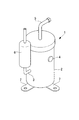
本実施形態に示す空気調和装置の室外機は、図1に示す圧縮機1と、圧縮機1の周囲を囲って外部への動作音の漏出を防止する圧縮機の遮音装置11(図2参照)と、室外熱交換器(図示せず)とを収納するものである。
ここで、図1において、符号2は圧縮機1の密閉ハウジング、符号3は冷媒を取り込むための吸入管、符号4は各種配線が接続される端子台、符号5は圧縮された冷媒を吐出するための吐出管、符号6は吸入管3に介装されて余剰冷媒を一時貯留するアキュームレータ、符号7はベースへの固定用の据付足である。
Hereinafter, an embodiment according to the present invention will be described with reference to the drawings.
The outdoor unit of the air conditioner shown in this embodiment includes a compressor 1 shown in FIG. 1 and a compressor
Here, in FIG. 1,
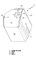
図2に示すように、圧縮機の遮音装置11は、シート状の遮音材12を折り曲げることによって立体的な形状に組立てられるものである。
本実施形態では、圧縮機の遮音装置11は、圧縮機1及びアキュームレータ6の周囲及び上方を囲む箱状に形成されている。具体的には、圧縮機の遮音装置11は、圧縮機1及びアキュームレータ6の周囲を囲む4枚の側壁12a,12b,12c,12dと、これら側壁12a〜12dによって囲まれる空間の上端を覆う天井部12eとを有している。
As shown in FIG. 2, the
In this embodiment, the
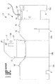
遮音材12は、ゴムシートの片面側にフェルトを貼り付けたものであって、図3の展開図に示すように、側壁12a〜12dがそれぞれ側辺を隣接する側壁と接続され、これら側壁12a〜12dのうちのいずれか一つの側壁の上端に、天井部12eが接続された構成とされている。本実施の形態では、天井部12eは、側壁12bの上端に接続されている。また、組立時に側壁12bに対向する側壁12dの上端には、天井部12eに重なる舌部12fが設けられている。そして、側壁12a,12c,12dの下端には、それぞれ、圧縮機1に接続された配管や配線を挿通させるためのスリットSが設けられている。
The sound insulating
この遮音材12は、これら側壁12a,12b,12c,12d,天井部12e、及び舌部12fの境界線に沿って折り曲げることにより、図2に示すような箱形状に組み立てられるようになっている。なお、遮音材12は、フェルト側が内側となるようにして組み立てられる。また、これら側壁12a,12b,12c,12d,天井部12e、及び舌部12fの境界線には、折り曲げが容易となるように、ミシン目が入れられている。
The
側壁12a及び12cの上端には、その縁部の端面から突出する凸部16が設けられている。また、天井部12eにおいて、側壁12aの上端に対向する部位、及び側壁12cの上端に対向する部位には、それぞれ凸部16が嵌合する開口部17が設けられている。
本実施形態では、嵌合部17は、天井部2eの縁部に開口する切り欠きによって構成されており、その幅方向の寸法αは、凸部16の幅方向の寸法βよりも小さく設定されている。
また、天井部12eにおいて側壁12dの上端側及び舌部12fには、巻き止め具21が設けられている。舌部12f側の巻き止め具21には、締め付け紐22が設けられている。
On the upper ends of the
In the present embodiment, the
Further, a
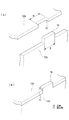
このように構成される圧縮機の遮音装置11では、図4に示すように、シート状の遮音材12を立体形状に組立てる際に、側壁12a,12cの上端縁に設けられた凸部16と、天井部12eのうち、この上端縁に対向する部位に設けられた開口部17とを嵌合させることで、これらの位置決め固定が行われる。
さらに、天井部12e及び舌部12fに設けられた巻き止め具21に締め付け紐22を巻きまわすことによって、天井部12eと舌部12fとが確実に固定されるようになっている。
In the compressor
Furthermore, the
本実施形態にかかる空気調和装置の室外機では、圧縮機の遮音装置11は、上記のように凸部16と開口部17とを嵌合させて組み立てるので、遮音材2の各部を確実に位置決め固定して所望の立体形状に形成しながら、かつ最低限の巻き止め具及び締め付け紐によって固定を行うことができる。これにより、図2に示すように、側壁12a〜12dに対して天井部12eが傾斜したような複雑な形状の圧縮機の遮音装置11についても、巻き止め具及び締め付け紐を最小限にしながら正確な形状に組み立てることができる。
凸部16及び開口部17は、圧縮機の遮音装置11を遮音材2のシートやロール等から切り出す際に形成することができるので、多数設置しても、部品点数は増加しない。
このため、この圧縮機の遮音装置11では、最小限の構成部材で所望の形状に正確に組立が可能であり、製造コストの低減や組立に要する時間の短縮を図ることができる。
In the outdoor unit of the air conditioner according to this embodiment, the
Since the
For this reason, in the
また、この圧縮機の遮音装置11では、開口部17の幅αが、凸部16の幅βよりも小さく設定されているので、これらが嵌合状態になったのちは分離しにくく、強固な固定を実現することができる。
Further, in the
ここで、本実施形態では、開口部17を、縁部に開口する切り欠きによって構成した例を示したが、これに限られることなく、開口部17は、遮音材2の厚み方向に貫通する穴部によって構成されていてもよい。
Here, in this embodiment, although the example which comprised the
11 圧縮機の遮音装置
12 遮音材
16 凸部
17 開口部
11 Compressor
Claims (3)
前記遮音材の縁部には、該縁部の端面から突出する凸部が設けられており、
前記遮音材のうち、組立時に前記縁部に対向する部位には、前記凸部が嵌合する開口部が設けられている圧縮機の遮音装置。 A sound insulation device for a compressor assembled into a three-dimensional shape by bending a sheet-like sound insulation material,
The edge of the sound insulating material is provided with a convex portion protruding from the end face of the edge,
A sound insulation device for a compressor, wherein an opening for fitting the convex portion is provided at a portion of the sound insulation material that faces the edge during assembly.
Priority Applications (1)
| Application Number | Priority Date | Filing Date | Title |
|---|---|---|---|
| JP2005063057A JP2006242543A (en) | 2005-03-07 | 2005-03-07 | Sound insulating device of compressor and outdoor unit of air conditioner using this device |
Applications Claiming Priority (1)
| Application Number | Priority Date | Filing Date | Title |
|---|---|---|---|
| JP2005063057A JP2006242543A (en) | 2005-03-07 | 2005-03-07 | Sound insulating device of compressor and outdoor unit of air conditioner using this device |
Publications (1)
| Publication Number | Publication Date |
|---|---|
| JP2006242543A true JP2006242543A (en) | 2006-09-14 |
Family
ID=37049133
Family Applications (1)
| Application Number | Title | Priority Date | Filing Date |
|---|---|---|---|
| JP2005063057A Withdrawn JP2006242543A (en) | 2005-03-07 | 2005-03-07 | Sound insulating device of compressor and outdoor unit of air conditioner using this device |
Country Status (1)
| Country | Link |
|---|---|
| JP (1) | JP2006242543A (en) |
Cited By (4)
| Publication number | Priority date | Publication date | Assignee | Title |
|---|---|---|---|---|
| JP2012247095A (en) * | 2011-05-26 | 2012-12-13 | Sanyo Electric Co Ltd | Cover, and outdoor unit of air conditioning device |
| EP3290697A4 (en) * | 2015-04-28 | 2018-12-05 | Daikin Industries, Ltd. | Soundproof cover of compressor for air conditioner |
| EP3486574A4 (en) * | 2016-07-13 | 2019-06-26 | Daikin Industries, Ltd. | Compressor cover for air treatment device |
| DE112018007662B4 (en) | 2018-05-25 | 2022-10-13 | Mitsubishi Electric Corporation | COMPRESSOR UNIT, OUTDOOR UNIT OF AN AIR CONDITIONING SYSTEM AND AIR CONDITIONING |
-
2005
- 2005-03-07 JP JP2005063057A patent/JP2006242543A/en not_active Withdrawn
Cited By (5)
| Publication number | Priority date | Publication date | Assignee | Title |
|---|---|---|---|---|
| JP2012247095A (en) * | 2011-05-26 | 2012-12-13 | Sanyo Electric Co Ltd | Cover, and outdoor unit of air conditioning device |
| EP3290697A4 (en) * | 2015-04-28 | 2018-12-05 | Daikin Industries, Ltd. | Soundproof cover of compressor for air conditioner |
| US10677477B2 (en) | 2015-04-28 | 2020-06-09 | Daikin Industries, Ltd. | Soundproof cover of compressor for air conditioner |
| EP3486574A4 (en) * | 2016-07-13 | 2019-06-26 | Daikin Industries, Ltd. | Compressor cover for air treatment device |
| DE112018007662B4 (en) | 2018-05-25 | 2022-10-13 | Mitsubishi Electric Corporation | COMPRESSOR UNIT, OUTDOOR UNIT OF AN AIR CONDITIONING SYSTEM AND AIR CONDITIONING |
Similar Documents
| Publication | Publication Date | Title |
|---|---|---|
| AU2011203018B2 (en) | Refrigerant distribution unit for air conditioner | |
| US7173186B1 (en) | Dual-sided mounting bracket for electrical junction boxes and method | |
| AU2011203020B2 (en) | Refrigerant distribution unit for air conditioner | |
| JP2008050814A (en) | Exterior wall structure and exterior wall panel for building | |
| US11149968B2 (en) | Heat source unit | |
| JP2006292231A (en) | Machine chamber | |
| JP2006242543A (en) | Sound insulating device of compressor and outdoor unit of air conditioner using this device | |
| JP4945357B2 (en) | Indoor unit of ceiling-embedded air conditioner | |
| US7677503B2 (en) | Rework bracket for electrical outlet boxes | |
| WO2016203542A1 (en) | Air conditioner outdoor unit | |
| JP2007078220A (en) | Outdoor unit of air conditioner | |
| JP6681004B2 (en) | Cover for compressor | |
| JP2003254551A (en) | Ceiling embedded type air conditioner | |
| JP6384304B2 (en) | Electromagnetic expansion valve unit | |
| JP2009186061A (en) | Outdoor unit and air conditioner equipped with the same | |
| JP2008020106A (en) | Outdoor unit of air conditioner | |
| KR102490582B1 (en) | Soundproof apparatus | |
| JP2008095978A (en) | Outdoor unit for air conditioner | |
| JPWO2017179141A1 (en) | Recessed ceiling air conditioner | |
| JP5556650B2 (en) | Enclosure | |
| JPH11325643A (en) | Refrigeration unit | |
| KR200291324Y1 (en) | assembling structure of compressor for out-door unit of air-conditioner | |
| JP2002012021A (en) | Air-conditioning unit for vehicle | |
| JP2008047439A (en) | Ceiling-recessed type lighting apparatus | |
| KR20020027863A (en) | The sealing apparatus for air-conditioner |
Legal Events
| Date | Code | Title | Description |
|---|---|---|---|
| A300 | Withdrawal of application because of no request for examination |
Free format text: JAPANESE INTERMEDIATE CODE: A300 Effective date: 20080513 |