WO2016174952A1 - 筆記データ処理装置 - Google Patents
筆記データ処理装置 Download PDFInfo
- Publication number
- WO2016174952A1 WO2016174952A1 PCT/JP2016/058334 JP2016058334W WO2016174952A1 WO 2016174952 A1 WO2016174952 A1 WO 2016174952A1 JP 2016058334 W JP2016058334 W JP 2016058334W WO 2016174952 A1 WO2016174952 A1 WO 2016174952A1
- Authority
- WO
- WIPO (PCT)
- Prior art keywords
- group
- entry frame
- distance
- size
- cpu
- Prior art date
- Legal status (The legal status is an assumption and is not a legal conclusion. Google has not performed a legal analysis and makes no representation as to the accuracy of the status listed.)
- Ceased
Links
Images
















Classifications
-
- G—PHYSICS
- G06—COMPUTING OR CALCULATING; COUNTING
- G06F—ELECTRIC DIGITAL DATA PROCESSING
- G06F3/00—Input arrangements for transferring data to be processed into a form capable of being handled by the computer; Output arrangements for transferring data from processing unit to output unit, e.g. interface arrangements
- G06F3/01—Input arrangements or combined input and output arrangements for interaction between user and computer
- G06F3/048—Interaction techniques based on graphical user interfaces [GUI]
- G06F3/0487—Interaction techniques based on graphical user interfaces [GUI] using specific features provided by the input device, e.g. functions controlled by the rotation of a mouse with dual sensing arrangements, or of the nature of the input device, e.g. tap gestures based on pressure sensed by a digitiser
- G06F3/0488—Interaction techniques based on graphical user interfaces [GUI] using specific features provided by the input device, e.g. functions controlled by the rotation of a mouse with dual sensing arrangements, or of the nature of the input device, e.g. tap gestures based on pressure sensed by a digitiser using a touch-screen or digitiser, e.g. input of commands through traced gestures
- G06F3/04883—Interaction techniques based on graphical user interfaces [GUI] using specific features provided by the input device, e.g. functions controlled by the rotation of a mouse with dual sensing arrangements, or of the nature of the input device, e.g. tap gestures based on pressure sensed by a digitiser using a touch-screen or digitiser, e.g. input of commands through traced gestures for inputting data by handwriting, e.g. gesture or text
-
- G—PHYSICS
- G06—COMPUTING OR CALCULATING; COUNTING
- G06F—ELECTRIC DIGITAL DATA PROCESSING
- G06F3/00—Input arrangements for transferring data to be processed into a form capable of being handled by the computer; Output arrangements for transferring data from processing unit to output unit, e.g. interface arrangements
- G06F3/01—Input arrangements or combined input and output arrangements for interaction between user and computer
- G06F3/03—Arrangements for converting the position or the displacement of a member into a coded form
- G06F3/033—Pointing devices displaced or positioned by the user, e.g. mice, trackballs, pens or joysticks; Accessories therefor
- G06F3/0354—Pointing devices displaced or positioned by the user, e.g. mice, trackballs, pens or joysticks; Accessories therefor with detection of two-dimensional [2D] relative movements between the device, or an operating part thereof, and a plane or surface, e.g. 2D mice, trackballs, pens or pucks
- G06F3/03545—Pens or stylus
-
- G—PHYSICS
- G06—COMPUTING OR CALCULATING; COUNTING
- G06V—IMAGE OR VIDEO RECOGNITION OR UNDERSTANDING
- G06V10/00—Arrangements for image or video recognition or understanding
- G06V10/20—Image preprocessing
- G06V10/22—Image preprocessing by selection of a specific region containing or referencing a pattern; Locating or processing of specific regions to guide the detection or recognition
- G06V10/235—Image preprocessing by selection of a specific region containing or referencing a pattern; Locating or processing of specific regions to guide the detection or recognition based on user input or interaction
-
- G—PHYSICS
- G06—COMPUTING OR CALCULATING; COUNTING
- G06V—IMAGE OR VIDEO RECOGNITION OR UNDERSTANDING
- G06V10/00—Arrangements for image or video recognition or understanding
- G06V10/20—Image preprocessing
- G06V10/25—Determination of region of interest [ROI] or a volume of interest [VOI]
-
- G—PHYSICS
- G06—COMPUTING OR CALCULATING; COUNTING
- G06V—IMAGE OR VIDEO RECOGNITION OR UNDERSTANDING
- G06V30/00—Character recognition; Recognising digital ink; Document-oriented image-based pattern recognition
- G06V30/10—Character recognition
- G06V30/14—Image acquisition
- G06V30/142—Image acquisition using hand-held instruments; Constructional details of the instruments
- G06V30/1423—Image acquisition using hand-held instruments; Constructional details of the instruments the instrument generating sequences of position coordinates corresponding to handwriting
-
- G—PHYSICS
- G06—COMPUTING OR CALCULATING; COUNTING
- G06V—IMAGE OR VIDEO RECOGNITION OR UNDERSTANDING
- G06V30/00—Character recognition; Recognising digital ink; Document-oriented image-based pattern recognition
- G06V30/10—Character recognition
- G06V30/32—Digital ink
-
- G—PHYSICS
- G06—COMPUTING OR CALCULATING; COUNTING
- G06V—IMAGE OR VIDEO RECOGNITION OR UNDERSTANDING
- G06V30/00—Character recognition; Recognising digital ink; Document-oriented image-based pattern recognition
- G06V30/40—Document-oriented image-based pattern recognition
- G06V30/41—Analysis of document content
- G06V30/412—Layout analysis of documents structured with printed lines or input boxes, e.g. business forms or tables
Definitions
- the present invention relates to a writing data processing apparatus that corrects misalignment of characters and the like.
- a writing data processing apparatus that processes stroke data corresponding to characters written on a paper medium.
- a positional deviation may occur between a ruled line based on data corresponding to the paper medium and a locus based on the stroke data due to a positional deviation of the paper medium.
- a writing data processing apparatus that corrects misalignment has been proposed.
- the correction apparatus described in Patent Document 1 stores a reference mark that is a reference for correcting the position of a locus based on stroke data, and a surrounding area that is an area around the reference mark. The user writes on the paper medium along the reference mark.
- the correction device corrects the position of the trajectory based on the stroke data based on the amount of deviation between the trajectory based on the stroke data included in the surrounding area and the reference mark. To do.
- the paper medium may include, for example, a name, date, and an entry frame in which the user can enter various items.
- a positional deviation or the like of the paper medium occurs, a positional deviation may occur between the entry frame based on the data corresponding to the paper medium and the locus based on the stroke data.
- An object of the present invention is to provide a writing data processing apparatus for moving a locus in an entry frame by a new correction method.
- the writing data processing apparatus is acquired by a stroke data acquiring unit that acquires a plurality of stroke data indicating a trajectory of a writing unit on a placement unit on which a paper medium is placed, and the stroke data acquiring unit. Further, among the trajectories based on the plurality of stroke data, a group specifying unit that specifies the trajectories within a predetermined distance from each other as a group, and a group region that is an area including the group specified by the group specifying unit are acquired.
- An entry frame selection that selects the entry frame that has the largest area overlapping the group area.
- the writing data processing device corrects the positional deviation of the locus based on the stroke data based on the positions of the entry frame based on the entry frame data included in the paper medium data and the locus based on the stroke data. Thereby, the writing data processing apparatus can move the locus into the entry frame.
- the group can be moved to the entry frame intended by the user than when the group is moved to an entry frame other than the entry frame having the largest area overlapping the group area.
- the writing data processing apparatus can reduce the time and effort for the user to fill in along the reference mark.
- the storage unit stores the entry frame data of the square entry frame
- the group region acquisition unit includes a rectangular region including the group identified by the group identification unit.
- the position correction unit is configured to provide a position between a side on a first direction side in a facing direction where a pair of sides of the entry frame face each other and a side on the first direction side of the group area.
- a first distance acquisition means a first movement means for moving the group in the opposite direction by the smaller distance of the first distance and the second distance acquired by the first distance acquisition means; in front A third distance between a side on the third direction side of the orthogonal direction orthogonal to the opposing direction in the entry frame and a side on the third direction side of the group region, and the third direction in the entry frame Acquired by the second distance acquisition means, the second distance acquisition means for acquiring a fourth distance between the side on the fourth direction side opposite to the side of the group area and the side of the group area on the fourth direction side
- a second moving means for moving the group in the orthogonal direction by a smaller distance of the third distance and the fourth distance.
- the writing data processing device moves the group in the facing direction by the larger distance between the first distance and the second distance, and the larger one of the third distance and the fourth distance.
- the trajectory included in the group can be moved into the entry frame with a small movement amount.
- the position correction unit is configured such that the center of the entry frame selected by the entry frame selection unit and the center of the group region acquired by the group region acquisition unit are at the same position.
- the group may be moved.
- the writing data processing apparatus can move the locus included in the group to the center of the entry frame. Therefore, the writing data processing apparatus improves the quality in appearance when the trajectory included in the group is displayed or printed, for example, by superimposing the trajectory on the image of the paper medium, compared to the case where the trajectory included in the group is arranged at the corner of the entry frame. To let you.
- the writing data processing apparatus comprises: a comparison unit that compares the size of the group area acquired by the group area acquisition unit with the size of the entry frame selected by the entry frame selection unit; and a comparison by the comparison unit Depending on the result, a size correction means for changing the size of the locus included in the group from which the group area has been acquired by the group area acquisition means may be provided.
- the writing data processing device changes the size of the locus according to the size of the group area and the size of the entry frame, for example, displays the locus superimposed on the image of the paper medium based on the paper medium data, or When printed, the appearance quality can be improved.
- the size correction unit is configured such that the size of the group region acquired by the group region acquisition unit is selected by the input frame selection unit as a result of the comparison by the comparison unit.
- the size of the locus included in the group may be changed so that the size of the group area is reduced to be equal to or smaller than the size of the entry frame.
- the writing data processing apparatus can change the size to fit the locus in the entry frame.
- the writing data processing apparatus can improve the quality of the appearance when, for example, a trajectory is superimposed on a paper medium for display or printing.
- the size correction unit is configured such that the size of the group region acquired by the group region acquisition unit is selected by the input frame selection unit as a result of the comparison by the comparison unit.
- the size of the trajectory included in the group may be changed so that the size of the group region is enlarged within a range equal to or smaller than the size of the entry frame. In this case, the trajectory is enlarged within a range that fits within the entry frame. For this reason, the writing data processing apparatus can improve the visibility of the locus in the entry frame, for example, when the locus is superimposed on a paper medium image and displayed or printed.
- the writing data processing device includes a display control unit that displays an image of the paper medium based on the paper medium data on a display unit, and the image based on the entry frame data in the image of the paper medium displayed by the display control unit.
- Receiving means for receiving an instruction to select an entry frame wherein the entry frame selection means includes the entry frame based on at least one entry frame data included in the paper medium data stored in the storage unit, The first entry frame that is the largest entry frame that overlaps the group area acquired by the group area acquisition unit is presented on the image of the paper medium displayed on the display unit by the display control unit. And an instruction to select either the first entry frame or the second entry frame that is different from the first entry frame, received by the accepting unit.
- the position correction unit may move the group in which the group area is acquired by the group area acquisition unit into the entry frame selected by the entry frame selection unit.
- the writing data processing apparatus can make the user select an entry frame. Therefore, since the user can move the locus to a desired entry frame, the convenience for the user can be improved. Also, the first entry frame having the largest entry frame that overlaps the group area among the entry frames is presented on the image of the paper medium. For this reason, the user can easily confirm the entry frame having the largest overlapping area. Therefore, the writing data processing apparatus can improve the convenience of the user when inputting an instruction to select an entry frame.
- the group specifying unit specifies a plurality of the groups
- the group region acquisition unit includes the group specifying unit for the one group among the plurality of groups specified by the group specifying unit.
- the group area is acquired, and the position correction unit moves the group in which the group area is acquired by the group area acquisition unit and moves the group in the entry frame selected by the entry frame selection unit.
- Other groups may be moved by the same amount of movement as the group.
- the writing data processing apparatus can move other groups by the same movement amount as one group. For this reason, the writing data processing apparatus can reduce the processing load as compared with the case where the positional deviation is corrected based on the positions of the entry frame and the locus for each of all the groups.
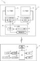
- FIG. 1 is a configuration diagram of a handwriting input system 1.
- FIG. It is a figure which shows the electrical structure of the handwriting input system.
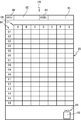
- 2 is a diagram illustrating an example of a sheet 700 of a paper medium 100.
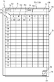
- FIG. It is an image of the paper medium 101 based on the paper medium data.
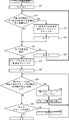
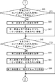
- It is a flowchart of a group specific process. It is a state transition diagram of a locus in main processing.
- FIG. 20 is a flowchart continued from FIG. 19.
- FIG. It is a figure which shows an example of the image displayed on the display 48 in 5th embodiment. It is a figure which shows an example of the image after the position of a locus
- FIG. 1 the outline
- the upper left side, lower right side, upper side, lower side, upper right side, and lower left side in FIG. 1 are defined as the left side, right side, upper side, lower side, rear side, and front side of the reading device 2, respectively. .
- the handwriting input system 1 includes a reading device 2, an electronic pen 3, a PC 4, and the like.
- the user enters text (characters, numbers, symbols, figures, etc.) on the paper medium 100 fixed to the reading device 2 using the electronic pen 3.
- the reading device 2 detects a trajectory of the electronic pen 3 for entering text on the paper medium 100 and acquires stroke data described later.
- the PC 4 can create data or the like obtained by digitizing text entered on the paper medium 100.
- the reading device 2 has a pair of left and right sensor substrates 7L and 7R.
- the sensor substrates 7L and 7R have the same shape.
- the sensor substrates 7L and 7R are rectangular thin plates.
- the sensor substrates 7L and 7R can be spread in the left-right direction.
- a large number of elongated loop coils are arranged in each of the sensor substrates 7L and 7R in the X-axis direction and the Y-axis direction.
- the sensor substrates 7L and 7R can be folded.
- the reading device 2 is a thin and lightweight handwriting input device.
- the electronic pen 3 is a known electromagnetic induction type electronic pen.
- the electronic pen 3 includes a core body 31, a coil 32, a variable capacitor 33, a substrate 34, a capacitor 35, and an ink storage unit 36.
- the core body 31 is provided at the tip of the electronic pen 3.
- the core body 31 is urged toward the distal end side of the electronic pen 3 by an elastic member (not shown).
- the tip of the core 31 protrudes outside the electronic pen 3.
- the rear end side of the core 31 is connected to an ink storage portion 36 that stores ink.
- the ink storage unit 36 supplies ink to the core body 31.
- the coil 32 is held between the core body 31 and the variable capacitor 33 while being wound around the ink storage portion 36.
- the variable capacitor 33 is fixed inside the electronic pen 3 by the substrate 34.
- a capacitor 35 is mounted on the substrate 34. The capacitor 35 and the variable capacitor 33 are connected in parallel to the coil 32 and constitute a known resonance circuit.
- the paper medium 100 can be spread in the left-right direction.
- a pair of front covers (a front cover 110L and a back cover 110R) and a plurality of papers 120 are bound at a part of each edge.
- the paper medium 100 is an A5 size notebook.
- the paper medium 100 is mounted on the reading device 2 such that the front cover 110L is placed on the upper surface of the sensor substrate 7L and the back cover 110R is placed on the upper surface of the sensor substrate 7R.
- the user With the paper medium 100 mounted on the reading device 2, the user can enter text on the paper 120 using the electronic pen 3.
- the position information of the electronic pen 3 for writing the text on the paper medium 100 is detected by one of the sensor substrates 7L and 7R facing the paper 120 on which the text is written.
- the electrical configuration of the handwriting input system 1 will be described with reference to FIG.
- the electrical configuration of the reading device 2 will be described.
- the reading device 2 includes sensor boards 7L and 7R, a main board 20, and sensor control boards 28 and 29.
- the main board 20 includes a CPU 21, a flash ROM 22, and a wireless communication unit 23.
- the flash ROM 22 and the wireless communication unit 23 are electrically connected to the CPU 21.
- the CPU 21 controls the reading device 2.
- the flash ROM 22 stores various programs that the CPU 21 executes to control the reading device 2.
- the flash ROM 22 stores stroke data.
- the stroke data includes a plurality of electronic pens 3 detected by the sensor substrates 7L and 7R over time when the locus of the electronic pen 3 when text is written on the paper medium 100 by the electronic pen 3 on the sensor substrates 7L and 7R. It is indicated by the position information.
- the stroke data includes coordinate information indicating each of a plurality of positions on the trajectory.
- the wireless communication unit 23 is a controller for executing short-range wireless communication with an external electronic device.
- the sensor board 7L is electrically connected to the ASIC 28A of the sensor control board 28.
- the ASIC 28A acquires stroke data based on the writing operation when the writing operation by the electronic pen 3 is performed on the sensor substrate 7L. Details will be described later.
- the sensor board 7R is electrically connected to the ASIC 29A of the sensor control board 29.
- the ASIC 29A acquires stroke data based on the writing operation when the writing operation by the electronic pen 3 is performed on the sensor substrate 7R. Details will be described later.
- the ASIC 28A on the master side is directly connected to the CPU 21, and the ASIC 29A on the slave side is connected to the CPU 21 via the ASIC 28A.
- the CPU 21 controls the ASICs 28A and 29A, and causes a current having a specific frequency to flow through each of the loop coils of the sensor substrates 7L and 7R. Thereby, a magnetic field is generated from each loop coil of the sensor substrates 7L and 7R.
- the resonance circuit of the electronic pen 3 resonates by electromagnetic induction and generates an induction magnetic field.
- the CPU 21 controls the ASICs 28A and 29A to stop the generation of magnetic fields from the loop coils of the sensor substrates 7L and 7R.
- the induction magnetic field generated from the resonance circuit of the electronic pen 3 is received by each loop coil of the sensor substrates 7L and 7R.
- the CPU 21 controls the ASICs 28A and 29A to detect reception currents flowing through the loop coils of the sensor boards 7L and 7R.
- the ASICs 28A and 29A execute this operation one by one for all the loop coils. Accordingly, the position of the electronic pen 3 is detected as coordinate information based on the received current.
- the electronic pen 3 when the electronic pen 3 is writing a text on the paper medium 100, writing pressure is applied to the core 31.
- the inductance of the coil 32 changes according to the writing pressure applied to the core body 31.
- the resonance frequency of the resonance circuit of the electronic pen 3 changes.
- the CPU 21 detects the change in the resonance frequency and specifies the writing pressure applied to the electronic pen 3.
- the CPU 21 can determine whether text is written on the paper medium 100 with the writing pressure specified from the electronic pen 3.
- the CPU 21 acquires stroke data including coordinate information indicating the position of the electronic pen 3 from the ASICs 28A and 29A.
- the CPU 21 stores the acquired stroke data in the flash ROM 22.
- the reading device 2 may detect the position of the electronic pen 3 by other methods.
- the reading device 2 may include a touch panel.
- the driving method of the touch panel is preferably a resistive film method.
- the paper medium 100 may be placed on the touch panel.
- CPU21 may detect the position where writing pressure was applied via the touch panel, when the operation
- the electrical configuration of PC4 will be described.
- the PC 4 includes a CPU 41 that controls the PC 4.
- the CPU 41 is electrically connected to a hard disk drive (HDD) 42, a RAM 43, a wireless communication unit 44, an input circuit 45, and an output circuit 46.
- the HDD 42 stores various data such as various programs executed by the CPU 41.
- a program for executing a main process (see FIG. 5) described later is also stored in the HDD 42.
- the PC 4 includes a medium reading device (for example, a CD-ROM drive) not shown.
- the PC 4 can read a program stored in a storage medium (for example, a CD-ROM) with a medium reader and install it in the HDD 42.
- the CPU 41 may receive a program from an external device (not shown) connected to the PC 4 or a network and install it in the HDD 42.
- the RAM 43 stores various temporary data.
- the wireless communication unit 44 is a controller for executing short-range wireless communication with an external electronic device.
- the input circuit 45 sends an instruction from the input unit 47 (for example, a mouse, a keyboard, a touch panel, etc.) to the CPU 41.
- the output circuit 46 displays an image on the display 48 in response to an instruction from the CPU 41.
- the wireless communication unit 23 of the reading device 2 and the wireless communication unit 44 of the PC 4 can execute short-range wireless communication with each other.
- the reading device 2 transmits the stroke data stored in the flash ROM 22 to the PC 4 by short-range wireless communication.
- Communication when the stroke data is transmitted from the reading device 2 to the PC 4 is not limited to wireless communication but may be wired communication.
- a sheet 700 which is an example of the sheet 120 of the paper medium 100, will be described with reference to FIG.
- the lower side, upper side, left side, and right side of FIG. 3 are defined as the front side, rear side, left side, and right side of the sheet 700, respectively.
- the front-rear direction of the paper 700 or the direction close to the front-rear direction may be referred to as “vertical”.
- the left-right direction of the paper 700 or the direction close to the left-right direction may be referred to as “lateral”.
- the paper 700 is one page of the paper medium 100. Illustration of other pages of the paper medium 100 is omitted.
- the sheet 700 is provided with an item column 74, an entry frame 75, and a check column 79.
- items “DATE”, “NAME”, “01” to “16”, and “A” to “G” are described.
- the entry frame 75 has a quadrangular shape, and a plurality of entry frames 75 are provided. More specifically, the entry frame 75 is provided on the right side of each of “DATE” and “NAME” in the item column 74.
- a plurality of entry frames 75 are arranged in front of each of the item columns 74 “A” to “G” and to the right of each of “01” to “16”.
- the check column 79 is square and is provided at the right front portion of the sheet 700. On the upper side of the check column 79, a character 78 of “SAVE” is described.
- Paper medium data that is data corresponding to paper medium 100 (see FIG. 3) will be described.
- Paper medium data is stored in the HDD 42.
- a paper medium 101 shown in FIG. 4 is a paper medium based on paper medium data.
- the paper medium data includes data of a set of coordinate information in the item column 84, the entry frame 85, the characters 88, and the check column 89.
- the item column 84, entry frame 85, character 88, and check column 89 correspond to the item column 74, entry frame 75, character 78, and check column 79 of the paper medium 100 (see FIG. 3), respectively.
- the coordinate information corresponds to the coordinate information on the sensor substrate 7L.
- the coordinates on the sensor substrate 7L corresponding to the positions of the item column 74, the entry frame 75, the character 78, and the check column 79 of the paper medium 100 are The coordinates coincide with the coordinates of the item column 84, the entry frame 85, the characters 88, and the check column 89 based on the paper medium data.
- the image shown in FIG. 4 is displayed or printed.
- the coordinate in the left-right direction of the paper medium 101 in FIG. 4 is defined as the X coordinate
- the coordinate in the front-rear direction is defined as the Y coordinate.
- the right direction and the rear direction are positive directions
- the left direction and the front direction are negative directions.
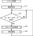
- the main process will be described with reference to FIG.
- the main processing is processing for correcting the position of the locus based on the stroke data.
- the user operates the input unit 47 and inputs an instruction to start an application for executing the main process.
- the CPU 41 of the PC 4 reads a program for executing the application from the HDD 42 and develops it in the RAM 43.
- the programs developed in the RAM 43 include programs for the CPU 41 to execute main processing.
- the CPU 41 executes main processing in accordance with a program command.
- the main process is ended when the user operates the input unit 47 and inputs an instruction to end the application for executing the main process.
- the user fills in the paper 700 of the paper medium 100 as shown in FIG. 6 is illustrated as a specific example.
- the user opens a page of the paper medium 100 and places the paper 700 on the sensor substrate 7L.
- the sheet 700 is shifted rightward with respect to the sensor substrate 7L.
- the user enters text in the entry frames 751 to 754 of the paper 700 using the electronic pen 3.
- the entry frames 751 to 754 are entry frames on the front side of the item columns 84 “A” to “D” and on the right side of the item column 84 “01”.
- the user enters the texts “123”, “68”, “90”, and “2” in the entry frames 751 to 754 using the electronic pen 3, respectively.
- the user enters a check mark 791 in the check column 79 using the electronic pen 3.
- the CPU 41 sets a connection with the CPU 21 of the reading device 2 via the wireless communication units 23 and 44.
- the CPU 41 sets a state in which communication with the CPU 21 of the reading device 2 is possible (S11).
- the CPU 41 determines whether or not stroke data has been acquired (S12). When the stroke data is not acquired (S12: NO), the CPU 41 repeats S12.
- the CPU 21 of the reading device 2 acquires the stroke data and stores it in the flash ROM 22.
- the CPU 21 determines that a check mark 791 has been entered at a position corresponding to the check field 79, the CPU 21 transmits the stroke data stored in the flash ROM 22 to the CPU 21 of the PC 4.
- CPU41 of PC4 performs a group specific process, when the transmitted stroke data is acquired (S12: YES) (S13).
- the texts “123”, “68”, “90”, and “2” are written in the center in the left-right direction of each of the entry frames 751 to 754.
- the sheet 700 is arranged in a state shifted to the right front with respect to the sensor substrate 7L, as shown in FIG.
- the group specifying process specifies, as a group, trajectories that are within a predetermined distance from each other based on the plurality of stroke data acquired in S12.
- various data such as various variables and trajectory groups are created and set.
- the data is stored in the RAM 43 or the HDD 42 as appropriate.
- CPU41 sets the variable N to 2 and sets the variable M to 1 (S21).
- the CPU 41 determines whether or not the distance between the Nth trajectory and the N ⁇ 1th trajectory is equal to or smaller than a predetermined distance (S22).
- S22 a predetermined distance
- the CPU 41 determines whether or not all the trajectories have been confirmed in S22 (S25).
- S25 an unconfirmed locus
- the CPU 41 increments the variable N (S26).
- CPU41 returns a process to S22.
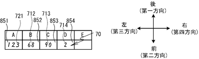
- FIG. 9A to 9C show a part of a diagram in which a trajectory based on stroke data is superimposed on the image of the paper medium 101 shown in FIG.
- the trajectories 801 to 803 are “1”, “2”, and “3” of the text “123”.
- the locus 804 is “6” of the text “68”.
- Trajectories 805 and 806 are “9” and “0” of the text “90”.
- the locus 807 is “8” of the text 68. That is, “6” and “8” of the text 68 are not described in a sequential order.
- the locus 808 is the text “2”.
- the trajectories “1”, “2”, and “3” of the text “123” are within a predetermined distance from each other. It is assumed that the trajectories “6” and “8” of the text “68” are within a predetermined distance from each other. It is assumed that the trajectories “9” and “0” of the text “90” are within a predetermined distance from each other. It is assumed that the trajectories of the texts “123”, “68”, “90”, and “2” are separated from each other by a predetermined distance.
- the distance between the second locus 802 “2” and the first locus “1” is within a predetermined distance. For this reason, when the variable N is 2, the CPU 41 determines that the distance between the second trajectory 802 and the first trajectory 801 is equal to or less than a predetermined distance (S22: YES). Since there is a locus that has not been confirmed (S25: NO), the CPU 41 sets N to 3 (S26), and returns the process to S22. The CPU 41 determines that the distance between the third locus 803 “3” and the second locus 802 “2” is within a predetermined distance (S22: YES), and sets N to 4 (S25: NO) , And S26), the process returns to S22.
- the CPU 41 determines that the distance between the fourth locus 804 “6” and the third locus 803 “3” is not within a predetermined distance (S22: NO).
- the CPU 41 groups the N-1th trajectories as the Mth group (M is the value of the variable M) (S23).
- M is the value of the variable M
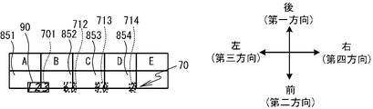
- FIG. 9B the trajectories from the first trajectory 801 “1” to the third trajectory 803 “3” are grouped as a first group 701 (S23).
- FIG. 9A to FIG. 9C the grouped group is shown surrounded by a dotted line.
- CPU41 increments the variable M (S24), and advances a process to S25.
- the processes of S22 to S26 are repeated, so that the second group 702 “6”, the third group 703 “90”, and the fourth group 704 “8” are grouped as shown in FIG. 9B. Is done.
- the user describes the locus 804 “6”, the locus 805 “9”, the locus 806 “0”, and the locus 807 “8” in this order. Therefore, as a result of the processing of S22 to S26, the trajectory 804 “6” and the trajectory 807 “8” are divided into different groups 702 and 704 even though they are within a predetermined distance.
- the trajectory 804 “6” and the trajectory 807 “8” divided into the different groups 702 and 704 are grouped by processing of S28 to S33 described later.
- the CPU 41 sets a variable P to 1 (S28).
- the CPU 41 selects the Pth group.
- the CPU 41 determines whether or not the distance between the selected locus in the Pth group and the locus in the other group is equal to or less than a predetermined distance (S29).
- a predetermined distance S29
- the CPU 41 determines that the distance between the trajectories 801 to 803 “123” in the first group 701 and the trajectories in other groups is not less than a predetermined distance ( S29: NO).
- the CPU 41 determines whether or not all groups have been selected in S29 (S32). When the group which has not been selected remains (S32: NO), the CPU 41 increments the variable P (S33), and returns the process to S29.
- the distance between the locus 804 “6” in the second group 702 shown in FIG. 9B and the locus 807 “8” in the fourth group 704 which is another group is equal to or less than a predetermined distance.
- S29: YES The CPU 41 groups the Pth group, which has been determined that the trajectory is equal to or less than the predetermined distance in S29, and other groups as the Pth group (S30). Next, the CPU 41 reassigns the group numbers after the Pth group and stores them in the RAM 43 (S31).
- the second group 702 “6” and the fourth group 704 “8” shown in FIG. 9B are grouped as a new second group 712 (S30).
- the trajectory 804 “6” and the trajectory 807 “8” are combined into one group.
- the third group 703 is set as a new third group 713
- the fifth group 705 is set as a new fourth group 714 (S31). After executing S31, the CPU 41 returns the process to S29.
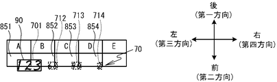
- the CPU 41 when S29 to S33 are repeated, as shown in FIG. 9C, the first group 701 “123”, the second group 712 “68”, the third group 713 “90”, and the fourth group 714 “2” is identified.
- the CPU 41 returns the process to the main process.
- the CPU 41 executes a correction process (S14).
- the first to fourth groups 701, 712, 713, and 714 may be collectively referred to as “group 70” or may not be specified.
- the group 70 is moved inside the entry frame 85 based on the entry frame data included in the paper medium data.
- the entry frame data included in the paper medium data stored in the HDD 42 is the entry frame data of the square entry frame 85.
- the back direction in the front-rear direction in which the pair of sides in the entry frame face each other may be referred to as a “first direction”, which is the direction opposite to the first direction.
- the direction may be referred to as a “second direction”.
- the left direction of the left and right directions orthogonal to the front-rear direction may be referred to as a “third direction”, and the right direction that is the opposite direction of the third direction may be referred to as a “fourth direction”.
- the CPU41 sets the variable q to 1 (S41).
- the CPU 41 acquires the group area 90 (see FIG. 11A) of the q-th group (S42).
- the group area 90 is an area including the group 70 identified in S13.
- the group area 90 acquired in S41 is a rectangular area.
- the variable q is 1, a group region 90 including the first group 701 is acquired as illustrated in FIG. 11A.
- the position of the Y coordinate closest to the first direction is the position in the front-rear direction of the side 951 on the first direction side, and
- the coordinate position is the position of the side 952 on the second direction side.
- the X coordinate position on the third direction side is the position of the side 953 on the third direction side
- the X coordinate on the fourth direction side is the position of the side 954 on the fourth direction side.
- An area surrounded by the sides 951 to 954 is acquired as the group area 90.
- the group region 90 is indicated by a solid square.
- the CPU 41 determines whether or not there is an entry frame 85 that overlaps the group area 90 acquired in S42 among the entry frames 85 based on at least one entry frame data included in the paper medium data. If it is determined (S43) that there is no entry frame 85 where the areas overlap (S43: NO), the CPU 41 advances the process to S51 described later.
- the CPU 41 selects the entry frame 85 that has the largest area that overlaps the group area 90 acquired in S42 among the entry frames 85 based on at least one entry frame data included in the paper medium data. Select (S44). In the specific example, the entry frame 851 having the largest area overlapping the group area 90 in FIG. 11A is selected.
- the CPU 41 moves the group 70 from which the group area 90 has been acquired in S42 into the entry frame 85 selected in S44 (S45 to S50). Details will be described below.
- the CPU 41 determines whether the group area 90 acquired in S42 is within the entry frame 85 selected in S44 in the front-rear direction (S45). In more detail using a specific example, the CPU 41 determines that the Y coordinate of the side 951 of the group area 90 shown in FIG. 11A is equal to or less than the Y coordinate of the side 861 on the first direction side of the entry frame 851 and the group area It is determined whether the Y coordinate of the side 952 of the 90 is equal to or greater than the Y coordinate of the side 862 on the second direction side of the entry frame 851.
- the first distance L1 is the first direction side edge 861 in the entry frame 851 selected in S44 and the first direction side of the group area 90 acquired in S42.
- the second distance L2 is a distance between the second direction side edge 862 in the entry frame 851 selected in S44 and the second direction side edge 952 of the group area 90 acquired in S42.
- the CPU 41 moves the group 701 having acquired the group region 90 in S42 in the front-rear direction by a smaller distance from the first distance L1 and the second distance L2 acquired in S46 (S47). .
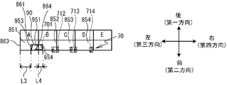
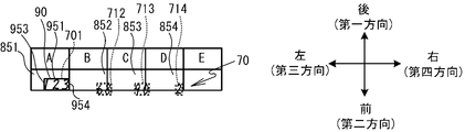
- the smaller distance between the first distance L1 and the second distance L2 is the second distance L2. Therefore, the CPU 41 moves the group 701 in the first direction by the second distance L2.
- the group 701 is positioned inside the entry frame 85 in the front-rear direction.
- the CPU 41 determines whether or not the group area 90 acquired in S42 is within the entry frame 85 selected in S44 (S48). More specifically, the CPU 41 determines that the X coordinate of the side 953 on the third direction side of the group region 90 shown in FIG. 11C is equal to or greater than the X coordinate of the side 863 on the third direction side of the entry frame 851. It is determined whether or not the X coordinate of the side 954 on the fourth direction side 90 is equal to or less than the X coordinate of the side 864 on the fourth direction side of the entry frame 851.
- the third distance L3 is between the side 863 on the third direction side in the entry frame 851 selected in S44 and the side 953 on the third direction side of the group area 90 acquired in S42. Is the distance.
- the fourth distance L4 is a distance between the side 864 on the fourth direction side in the entry frame 851 selected in S44 and the side 954 on the fourth direction side of the group region 90 acquired in S42.
- the CPU 41 moves the group 70, which has acquired the group area 90 in S42, in the left-right direction by a smaller distance from the third distance L3 and the fourth distance L4 acquired in S46 (S50). .
- the smaller distance between the third distance L3 and the fourth distance L4 is the fourth distance L4. Therefore, the CPU 41 moves the group 701 in the third direction by the fourth distance L4.
- the locus included in the group 701 is positioned inside the entry frame 851 in the left-right direction.
- the CPU 41 determines whether or not the group area 90 has been acquired in S42 for all the groups 70 (S51). When there is a group area 90 that has not acquired the group area 90 (S51: NO), the CPU 41 increments the variable q (S52), and returns the process to S42.
- the loci included in the first to fourth groups 701, 712, 713, and 714 are positioned in the entry frames 851 to 854, respectively, as shown in FIG. It becomes.
- the stroke data in which the trajectories included in the first to fourth groups 701, 712, 713, and 714 are located in the entry frames 851 to 854 are stored in the HDD.
- the PC 4 corrects the positional deviation of the locus based on the stroke data based on the positions of the entry frame 85 based on the entry frame data included in the paper medium data and the locus based on the stroke data. Then, the locus can be moved into the entry frame 85 (see FIGS. 9A and 12).
- the possibility that the group 70 can be moved to the entry frame 85 intended by the user is increased.
- PC4 moves the group 70 in the front-rear direction by the smaller distance of the first distance L1 and the second distance L2, and the smaller distance of the third distance L3 and the fourth distance L4, The group 70 is moved in the left-right direction.
- the PC 4 can move the trajectory included in the group 70 within the entry frame 85 (S45 to S50). Therefore, the PC 4 moves the group 70 in the front-rear direction by the larger distance between the first distance L1 and the second distance L2, and the larger one of the third distance L3 and the fourth distance L4.
- the trajectory included in the group 70 can be moved into the entry frame 85 with a smaller amount of movement than when moving the group 70 in the left-right direction by the distance.
- the PC 4 moves the group 70 with a smaller movement amount than when moving the group 70 so that the center of the entry frame 85 selected in S44 and the center of the group area 90 acquired in S42 are at the same position.
- the trajectory included in 70 can be moved into the entry frame 85.
- the PC 4 is an example of the “writing data processing device” of the present invention.
- the electronic pen 3 is an example of the “writing means” in the present invention.
- the CPU 41 that performs the process of S12 is an example of the “stroke data acquisition means” in the present invention.
- the CPU 41 that performs the process of S13 is an example of the “group specifying means” in the present invention.
- the CPU 41 that performs the process of S42 is an example of the “group area acquisition unit” in the present invention.
- the CPU 41 that performs the process of S44 is an example of the “entry box selection means” in the present invention.
- the CPU 41 that performs the processes of S45 to S50 is an example of the “position correcting means” in the present invention.
- the CPU 41 that performs the process of S46 is an example of the “first distance acquisition unit” in the present invention.
- the CPU 41 that performs the process of S47 is an example of the “first moving means” in the present invention.
- the CPU 41 that performs the process of S49 is an example of the “second distance acquisition unit” in the present invention.
- the CPU 41 that performs the process of S50 is an example of the “second moving means” in the present invention.
- the present invention is not limited to the above embodiment, and various modifications are possible.
- the method of moving the group 70 in the entry frame 85 is not limited to the above embodiment.
- the CPU 41 may move the group 70 so that the center of the entry frame 85 selected in S44 and the center of the group area 90 acquired in S42 are at the same position.
- this modification will be described as a second embodiment.
- FIG. 13 shows a modification of the correction process. In FIG. 13, processes similar to those in the first embodiment are denoted by the same step numbers, and detailed description thereof is omitted.
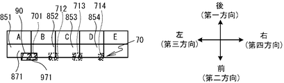
- FIG. 14A is a diagram in which the group region 90 of the group 701 is specified when the variable q is 1 as in FIG. 11A.
- the CPU 41 calculates the difference between the coordinates of the center 871 of the entry frame 851 selected in S44 and the coordinates of the center 971 of the group area 90 acquired in S42 (S61).
- the CPU 41 moves the group 701 by the difference calculated in S62 (S62).
- FIG. 14B the center 871 of the entry box 851 selected in S44 and the center 971 of the group area 90 acquired in S42 are at the same position.
- the CPU 41 executes the processing of S51 and S52, and returns the processing to S42 as in the case shown in FIG.
- the CPU 41 repeats the processes of S42 to S44, S61, S62, S51, and S52, and moves the trajectory included in each group 70 into the entry frame 85 as shown in FIG. 14C.
- the PC 4 can move the trajectory included in the first to fourth groups 701, 712, 713, and 714 to the center of the entry frames 851 to 854.
- the trajectory included in the group 70 is displayed or printed with the trajectory based on the stroke data superimposed on the image of the paper medium 101 based on the paper medium data, compared to the case where the trajectory included in the group 70 is arranged at the corner of the entry frame 85.
- the quality on the appearance is improved.
- the CPU 41 that performs the processes of S61 and S62 is an example of the “position correction unit” in the present invention.
- FIG. 15 shows a modification of the correction process.
- processes similar to those in the first embodiment and the second embodiment are denoted by the same step numbers, and detailed description thereof is omitted.
- the CPU 41 executes the processing of S41 to S44, as in the above embodiment.
- the CPU 41 compares the size of the group area 90 acquired in S42 with the size of the entry frame 85 selected in S44. As a result of the comparison, the CPU 41 determines whether or not the size of the group area 90 is larger than the size of the entry frame 85 (S71). When the size of the group area 90 is equal to or smaller than the size of the entry frame 85 (S71: NO), the CPU 41 advances the process to S61.
- the size of the locus included in the group 70 is changed so as to reduce the size of the group area 90 to be equal to or smaller than the size of the entry frame 85. (S72).
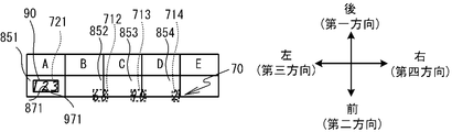
- FIG. 16A shows a case where the trajectory included in the first group 701 in FIG. 11A is described larger than the size of the entry frame 851.
- This group is referred to as a first group 721.
- the CPU 41 determines that the size of the group area 90 of the first group 721 is larger than the size of the entry frame 851 (S71: YES).
- the CPU 41 changes the size of the trajectory included in the first group 721 so as to reduce the size of the group area 90 to be equal to or smaller than the size of the entry frame 851 (S72).
- the CPU 41 reacquires the q-th group area 90 of the group 70 of the trajectory after the reduction, similarly to the case of S42 (S73).
- the CPU 41 executes the processes of S61 and S62 as in the above embodiment.
- the group area 90 (see FIG. 16B) reacquired in S73 is referred to instead of the group area 90 acquired in S42, and the processes in S61 and S62 are performed.
- the CPU 41 moves the reduced trajectory included in the first group 721 to the center of the entry frame 851.
- CPU41 returns a process to S42 after performing the process of S51 and S52 similarly to the said embodiment.
- the CPU 41 repeats the processes of S42 to S44, S71 to S73, S61, S62, S51, and S52.
- the trajectory included in each group 70 moves to the inside of the entry frames 851 to 854.
- the PC 4 changes the size and fills the entry frame. 85.
- the quality of the appearance when the trajectory based on the stroke data is displayed and printed on the image of the paper medium 101 based on the paper medium data is improved.
- FIG. 17 is a modification of the correction process.
- processes similar to those in the first to third embodiments are denoted by the same step numbers, and detailed description thereof is omitted.
- the CPU 41 executes the processes of S41 to S44 as in the above embodiment.
- the CPU 41 compares the size of the group area 90 acquired in S42 with the size of the entry frame 85 selected in S44. As a result of the comparison, the CPU 41 determines whether or not the size of the group area 90 is smaller than the size of the entry frame 85 (S81). When the size of the group area 90 is equal to or larger than the size of the entry frame 85 (S81: NO), the CPU 41 advances the process to S61.
- the CPU 41 is included in the group 70 so as to enlarge the size of the group area 90 within a range equal to or smaller than the size of the entry frame 85.
- the size of the trajectory to be changed is changed (S82).
- FIG. 18A is a view similar to FIG. 11A.
- the CPU 41 determines that the size of the group area 90 of the first group 721 is smaller than the size of the entry frame 851 (S81: YES).
- the CPU 41 changes the size of the trajectory included in the first group 701 so as to enlarge the size of the group region 90 within a range equal to or smaller than the size of the entry frame 851 (S82).
- the CPU 41 re-acquires the q-th group area 90 of the group of trajectories after the enlargement (S83).
- the CPU 41 executes the processes of S61 and S62 as in the case of FIG.
- the group area 90 acquired in S83 is referred to instead of the group area 90 acquired in S42, and the processes in S61 and S62 are performed.
- the CPU 41 moves the enlarged locus included in the group 70 to the center of the entry frame 85.
- CPU41 returns a process to S42 after performing the process of S51 and S52 similarly to the case of FIG.
- the CPU 41 repeats the processes of S42 to S44, S81 to S83, S61, S62, S51, and S52.
- the CPU 41 enlarges the trajectory included in the first to fourth groups 701, 712, 713, and 714 and moves it to the inside of the entry frames 851 to 854.
- the trajectory is enlarged within a range that fits in the entry frame 85. For this reason, for example, when the trajectory based on the stroke data is displayed or printed on the image of the paper medium 101 based on the paper medium data, the visibility of the trajectory in the entry frame 85 can be improved. Moreover, the quality on appearance improves.
- the CPU 41 compares the size of the group area 90 acquired in S42 with the size of the entry frame 85 selected in S44 (S71 and S81).
- the CPU 41 changes the size of the trajectory included in the group 70 that acquired the group area 90 in S42 according to the comparison result (S72 and S82).
- the image based on the stroke data is superimposed or displayed on the image of the paper medium 101 based on the paper medium data. In this case, the appearance quality can be improved.
- the CPU 41 that performs the processing of S71 (see FIG. 15) and S81 (see FIG. 17) is an example of the “comparison means” of the present invention.
- the CPU 41 that performs the processes of S72 (see FIG. 15) and S82 (see FIG. 17) is an example of the “size correcting means” in the present invention.
- the entry frame 85 is selected by the CPU 41 (S44). After selecting the entry frame 85, the CPU 41 may change the entry frame 85 to be selected based on a user instruction. The CPU 41 may move other groups 70 by the same movement amount when one group 70 is moved.
- S44 the CPU 41
- the CPU 41 may move other groups 70 by the same movement amount when one group 70 is moved.
- the CPU 41 executes the processes of S41 to S44 as in the above embodiment.
- CPU41 performs the process of S51 and S52, when there is no entry frame 85 which overlaps with the group area
- the entry frame 85 having the largest area overlapping with the group area 90 acquired in S42 (that is, The entry box 85) selected in S44 is referred to as a first entry box 85.
- An entry frame 85 different from the first entry frame 85 is referred to as a second entry frame 85.
- the CPU 41 displays the image of the paper medium 101 based on the paper medium data stored in the HDD 42 and the trajectory based on the stroke data on the display 48 as shown in FIG. 21 (S91).
- the display 48 is not shown.
- the CPU 41 presents the first entry frame 85 on the image of the paper medium 101 displayed on the display 48 in S91 (S92).
- the method of presenting the first entry frame 85 is not limited.
- the periphery of the first entry frame 85 may be blinked, or the color of the first entry frame 85 may be displayed in a color different from the color of the second entry frame 85.
- the first entry frame 85 (that is, entry frame 851) is displayed in a color different from that of the second entry frame 85.
- CPU41 judges whether the instruction
- the instruction to select the entry frame 85 is input to the PC 4 when the user operates the input unit 47 (see FIG. 2). For example, the user operates the input unit 47 to move the cursor 881 (see FIG. 21) displayed on the display 48 to select the entry frame 85.
- the CPU 41 repeats S93.
- the CPU 41 based on the instruction to select either the first entry frame 85 or the second entry frame 85 received in S93, The entry frame 85 is selected (S94). In the specific example shown in FIG. 21, it is assumed that the entry frame 855 below the entry frame 851 is selected.
- the CPU 91 determines whether or not the group area 90 is within the entry frame 85 selected in S94 (S95).
- the CPU 41 executes the processes of S45 to S50 as shown in FIG. That is, the CPU 41 moves the group 70 that has acquired the group area 90 in S42 into the entry frame 85 selected in S94.
- CPU41 moves the other group 70 by the same movement amount as the group 70 moved in S47 and S50 (S96). That is, the CPU 41 moves the group 70 into the entry frame 85 selected in S94 out of the first entry frame 85 and the second entry frame 85, and moves the other group 70 by the same movement amount. .
- the trajectories “68”, “90”, and “2” are moved by the same movement amount as the trajectory “123”. As a result, the trajectories “123”, “68”, “90”, and “2” move to the entry frames 855 to 858 below the entry frames 851 to 854.
- the CPU 41 ends the correction process, and returns the process to the main process.
- the CPU 41 executes the processes of S61 and S62. That is, the CPU 41 moves the group 70 that acquired the group area 90 in S42 so that the center of the entry frame 85 selected in S94 and the center of the group area 90 acquired in S42 are at the same position.
- the CPU 41 moves another group 70 by the same movement amount as the group 70 moved in S62 (S97). That is, the CPU 41 moves the group 70 into the entry frame 85 selected in S94 out of the first entry frame 85 and the second entry frame 85, and moves the other group 70 by the same movement amount. .
- the trajectories “123”, “68”, “90”, and “2” are within the entry frames 851 to 854, respectively, and the entry frame 851 that is the first entry frame 85 in S93. Is selected.
- the CPU 41 determines that the group area 90 of the locus “123” is within the entry frame 851 (S95: YES), and moves the locus “123” to the center of the entry frame 851 (S62).
- the other trajectories “68”, “90”, and “2” are moved by the amount of movement.
- the positional deviations of the trajectories “123”, “68”, “90”, and “2” with respect to the centers of the entry frames 851 to 854 tend to be the same distance from each other. Therefore, the trajectory “123”, “68” is obtained by moving the other trajectories “68”, “90”, “2” by the same amount of movement as the trajectory “123” moves to the center of the entry frame 851. ”,“ 90 ”, and“ 2 ”are easily located at the center of the entry frames 851 to 854, respectively.
- the CPU 41 ends the correction process and returns the process to the main process.
- the PC 4 can cause the user to select the entry frame 85 for moving the locus.
- the user can move the locus to a desired entry frame 85, and the convenience for the user is improved.
- the first entry frame 85 having the largest area overlapping with the group area 90 among the entry frames 85 is presented on the image of the paper medium 101 (S92). For this reason, the user can easily confirm the entry frame 85 having the largest area overlapping with the group area 90. Therefore, the convenience of the user when inputting an instruction to select the entry frame 85 is improved.
- Another group is moved by the same movement amount as the movement amount of the one group 70 from which the group area 90 was acquired in S42 (see FIG. 19). 70 is moved (S96 and S97). For this reason, it is possible to reduce the processing load of the CPU 41 as compared with the case where the positional deviation is corrected based on the positions of the entry frame 85 and the locus for each of the groups 70.
- the user selects the entry frame 85 only once (S93: YES), and the trajectory included in all the groups 70 moves at once (S47, S50, S96, S62, and S97). For this reason, compared with the case where a user selects the entry frame 85 many times, a user's convenience improves.
- the display 48 is an example of the “display unit” in the present invention.
- the CPU 41 that performs the process of S91 is an example of the “display control means” in the present invention.
- the CPU 41 that performs the process of S93 is an example of the “accepting means” in the present invention.
- the CPU 41 that performs the processes of S44, S91, and S94 is an example of the “entry box selection means” in the present invention.
- the CPU 41 that performs the processes of S62, S97, S45 to S50, and S96 is an example of the “position correcting means” in the present invention.
- the entry frame 85 is selected only once by the user (S93: YES), and the trajectories (S47, S50, S96, S62, and S97) included in all the groups 70 are moved. Has been.
- the other group 70 may be moved by the same movement amount. Even in this case, the processing load of the CPU 41 can be reduced as compared with the case where the positional deviation is corrected based on the positions of the entry frame 85 and the locus for each of the groups 70.
- the sheet 700 since the sheet 700 is arranged in a state shifted to the right front with respect to the sensor substrate 7L, the texts “123”, “68”, “90” based on the stroke data are arranged. ”And“ 2 ”are in a state of being shifted to the right front from the entry frames 851 to 854 based on the entry frame data.
- the cause of the position shift is not limited to this.
- the position shift of the coil 32 may occur due to the position of the coil 32 changing according to the inclination of the electronic pen 3 when the user writes.
- the entry frame 85 is a quadrangle, but it may be a shape different from the quadrangle.
- the main process was performed by CPU41 of PC4, it is not limited to this.
- the main process may be executed by the CPU 21 of the reading device 2.
- various data such as a program for executing the main processing may be stored in the flash ROM 22 instead of the HDD 42 and the RAM 43.
- the CPU 21 may transmit the corrected stroke data to the PC 4.
- the reading device 2 is an example of the “writing data processing device” of the present invention.
- the reading device 2 may be connected not to the PC 4 but to another mobile terminal or the like, and a CPU such as the mobile terminal may execute the main process.
- a display may be added to the reading device 2, and the image displayed on the display 48 in the above embodiment may be displayed on the display of the reading device 2.
Landscapes
- Engineering & Computer Science (AREA)
- Theoretical Computer Science (AREA)
- Physics & Mathematics (AREA)
- General Physics & Mathematics (AREA)
- Multimedia (AREA)
- Computer Vision & Pattern Recognition (AREA)
- General Engineering & Computer Science (AREA)
- Human Computer Interaction (AREA)
- Artificial Intelligence (AREA)
- User Interface Of Digital Computer (AREA)
Abstract
PCのCPUは、電子ペンの軌跡を示す複数のストロークデータを取得する。CPUは、複数のストロークデータに基づく軌跡のうち、互いに所定距離以内にある軌跡を第1グループ(70)として特定する。CPUは、特定した第1グループ(701)を含むグループ領域(90)を取得する。CPUは、紙媒体データに含まれる少なくとも1の記入枠データに基づく記入枠のうち、グループ領域(90)とが重なる領域が最も大きな記入枠(851)を選択する。CPUは、選択した記入枠(851)内に、グループ領域(90)が取得された第1グループ701を移動させる。CPUは、他のグループも第1グループ(701)と同様の処理によって移動させる。
Description
本発明は、文字等の位置ずれを補正する筆記データ処理装置に関する。
従来、紙媒体に筆記された文字等に対応するストロークデータを処理する筆記データ処理装置が知られている。筆記データ処理装置においては、紙媒体の位置ずれ等によって、紙媒体に対応するデータに基づく罫線等と、ストロークデータに基づく軌跡との間で位置ずれが発生する場合がある。このため、位置ずれを補正する筆記データ処理装置が提案されている。例えば、特許文献1に記載の補正装置は、ストロークデータに基づく軌跡の位置補正の基準となる基準マークと、基準マークの周囲の領域である周囲領域とを記憶する。ユーザは、基準マークに沿って紙媒体上に筆記する。補正装置は、取得されたストロークデータに基づく軌跡が周囲領域に含まれる場合、周囲領域に含まれるストロークデータに基づく軌跡と、基準マークとのずれ量に基づき、ストロークデータに基づく軌跡の位置を補正する。
紙媒体には、例えば、名前、日付、及び種々の項目をユーザが記入可能な記入枠が記載される場合がある。この場合、紙媒体の位置ずれ等が発生すると、紙媒体に対応するデータに基づく記入枠と、ストロークデータに基づく軌跡との間で位置ずれが生じる場合がある。
本発明の目的は、新たな補正方法により記入枠内に軌跡を移動させる筆記データ処理装置を提供することである。
本発明に係る筆記データ処理装置は、紙媒体が載置される載置部上における、筆記手段の軌跡を示す複数のストロークデータを取得するストロークデータ取得手段と、前記ストロークデータ取得手段によって取得された前記複数のストロークデータに基づく前記軌跡のうち、互いに所定距離以内にある前記軌跡をグループとして特定するグループ特定手段と、前記グループ特定手段によって特定された前記グループを含む領域であるグループ領域を取得するグループ領域取得手段と、記憶部に記憶された前記紙媒体に対応するデータである紙媒体データに含まれる少なくとも1の記入枠データに基づく記入枠のうち、前記グループ領域取得手段によって取得された前記グループ領域と重なる領域が最も大きな前記記入枠を選択する記入枠選択手段と、前記記入枠選択手段によって選択された前記記入枠内に、前記グループ領域取得手段によって前記グループ領域が取得された前記グループを移動させる位置補正手段とを備えている。
筆記データ処理装置は、紙媒体データに含まれる記入枠データに基づく記入枠と、ストロークデータに基づく軌跡との位置に基づいて、ストロークデータに基づく軌跡の位置ずれを補正する。これによって、筆記データ処理装置は、軌跡を記入枠内に移動させることができる。また、グループ領域と重なる領域が最も大きな記入枠以外の記入枠にグループが移動される場合に比べて、ユーザが意図した記入枠にグループを移動させることができる可能性が高くなる。また、従来のように、紙媒体上に基準マークを設ける必要がない。よって、基準マークを紙媒体上に設けるためのスペースを確保する必要がないので、紙媒体上のスペースを有効活用できる。また、筆記データ処理装置は、ユーザが基準マークに沿って記入を行う手間を削減できる。
前記筆記データ処理装置において、前記記憶部は、四角形の前記記入枠の前記記入枠データを記憶し、前記グループ領域取得手段は、前記グループ特定手段によって特定された前記グループを含む四角形の領域を、前記グループ領域として取得し、前記位置補正手段は、前記記入枠における一対の辺が対向する対向方向のうちの第一方向側の辺と、前記グループ領域の前記第一方向側の辺との間の第一距離と、前記記入枠における前記第一方向の反対方向である第二方向側の辺と、前記グループ領域の前記第二方向側の辺との間の第二距離とを取得する第一距離取得手段と、前記第一距離取得手段によって取得された前記第一距離と前記第二距離とのうち、小さい方の距離分、前記グループを前記対向方向に移動させる第一移動手段と、前記記入枠における前記対向方向に直交する直交方向のうちの第三方向側の辺と、前記グループ領域の前記第三方向側の辺との間の第三距離と、前記記入枠における前記第三方向の反対方向である第四方向側の辺と、前記グループ領域の前記第四方向側の辺との間の第四距離とを取得する第二距離取得手段と、前記第二距離取得手段によって取得された前記第三距離と前記第四距離とのうち、小さい方の距離分、前記グループを前記直交方向に移動させる第二移動手段とを備えている。この場合、筆記データ処理装置は、第一距離と第二距離とのうち、大きい方の距離分、グループを対向方向に移動させ、且つ、第三距離と第四距離とのうち、大きい方の距離分、グループを直交方向に移動させる場合に比べて、小さい移動量で、グループに含まれる軌跡を記入枠内に移動させることができる。
前記筆記データ処理装置において、前記位置補正手段は、前記記入枠選択手段によって選択された前記記入枠の中心と、前記グループ領域取得手段によって取得された前記グループ領域の中心とが同じ位置になるように、前記グループを移動させてもよい。この場合、筆記データ処理装置は、グループに含まれる軌跡を記入枠の中心に移動させることができる。従って、筆記データ処理装置は、グループに含まれる軌跡が記入枠の隅に配置される場合に比べて、例えば紙媒体の画像に軌跡を重ね合わせて表示又は印刷した場合、外観上の品質を向上させることがする。
前記筆記データ処理装置は、前記グループ領域取得手段によって取得された前記グループ領域のサイズと、前記記入枠選択手段によって選択された前記記入枠のサイズとを比較する比較手段と、前記比較手段による比較の結果に応じて、前記グループ領域取得手段によって前記グループ領域が取得された前記グループに含まれる前記軌跡のサイズを変更するサイズ補正手段とを備えてもよい。この場合、筆記データ処理装置は、グループ領域のサイズと記入枠のサイズとに応じて軌跡のサイズを変更することで、例えば、紙媒体データに基づく紙媒体の画像に軌跡を重ね合わせて表示又は印刷した場合、外観上の品質を向上させることができる。
前記筆記データ処理装置において、前記サイズ補正手段は、前記比較手段による比較の結果、前記グループ領域取得手段によって取得された前記グループ領域のサイズが、前記記入枠選択手段によって選択された前記記入枠のサイズより大きい場合に、前記グループ領域のサイズを前記記入枠のサイズ以下に縮小するように、前記グループに含まれる前記軌跡のサイズを変更してもよい。この場合、筆記データ処理装置は、グループ領域のサイズが記入枠のサイズより大きくても、サイズを変更して記入枠内に軌跡を収めることができる。また、筆記データ処理装置は、例えば紙媒体の画像に軌跡を重ね合わせて表示又は印刷した場合、外観上の品質を向上させることができる。
前記筆記データ処理装置において、前記サイズ補正手段は、前記比較手段による比較の結果、前記グループ領域取得手段によって取得された前記グループ領域のサイズが、前記記入枠選択手段によって選択された前記記入枠のサイズより小さい場合に、前記記入枠のサイズ以下の範囲内において、前記グループ領域のサイズを拡大するように、前記グループに含まれる前記軌跡のサイズを変更してもよい。この場合、記入枠内に収まる範囲で軌跡が拡大される。このため、筆記データ処理装置は、例えば紙媒体の画像に軌跡を重ね合わせて表示又は印刷した場合、記入枠内の軌跡の視認性を向上させることができる。
前記筆記データ処理装置は、前記紙媒体データに基づく前記紙媒体の画像を表示部に表示する表示制御手段と、前記表示制御手段によって表示された前記紙媒体の画像において前記記入枠データに基づく前記記入枠を選択する指示を受け付ける受付手段とを備え、前記記入枠選択手段は、前記記憶部に記憶された前記紙媒体データに含まれる少なくとも1の前記記入枠データに基づく前記記入枠のうち、前記グループ領域取得手段によって取得された前記グループ領域と重なる領域が最も大きな前記記入枠である第一記入枠を、前記表示制御手段によって前記表示部に表示された前記紙媒体の画像上に提示し、前記受付手段によって受け付けられた、前記第一記入枠と、前記第一記入枠とは異なる第二記入枠とのいずれかを選択する指示に基づき、前記記入枠を選択し、前記位置補正手段は、前記記入枠選択手段によって選択された前記記入枠内に、前記グループ領域取得手段によって前記グループ領域が取得された前記グループを移動させてもよい。この場合、筆記データ処理装置は、記入枠をユーザに選択させることができる。よって、ユーザは、所望の記入枠に軌跡を移動させることができるので、ユーザの利便性を向上させることができる。また、記入枠のうち、グループ領域と重なる領域が最も大きな記入枠である第一記入枠が、紙媒体の画像上に提示される。このため、ユーザは、重なる領域が最も大きな記入枠を確認し易い。よって、筆記データ処理装置は、記入枠を選択する指示を入力する場合におけるユーザの利便性を向上させることができる。
前記筆記データ処理装置において、前記グループ特定手段は、複数の前記グループを特定し、前記グループ領域取得手段は、前記グループ特定手段によって特定された複数の前記グループのうち、1の前記グループについて、前記グループ領域を取得し、前記位置補正手段は、前記記入枠選択手段によって選択された前記記入枠内に、前記グループ領域取得手段によって前記グループ領域が取得された前記グループを移動させるとともに、移動させる前記グループと同じ移動量分、他の前記グループを移動させてもよい。この場合、筆記データ処理装置は、1のグループと同じ移動量分、他のグループを移動させることができる。このため、筆記データ処理装置は、全てのグループの夫々について、記入枠と軌跡との位置に基づいて位置ずれを補正する場合に比べて、処理の負荷を低減できる。
本発明の実施形態について、図面を参照して説明する。図1を参照して、第一実施形態に係る手書入力システム1の概要を説明する。以下では、図1の左上側、右下側、上側、下側、右上側、左下側を、それぞれ、読取装置2の左側、右側、上側、下側、後側、前側と定義して説明する。
手書入力システム1は、読取装置2、電子ペン3、PC4等を含む。手書入力システム1では、ユーザが電子ペン3を用いて、読取装置2に固定された紙媒体100にテキスト(文字、数字、記号、図形等)を記入する。読取装置2は、紙媒体100にテキストを記入する電子ペン3の軌跡を検出して、後述のストロークデータを取得する。PC4は、読取装置2で取得されたストロークデータに基づいて、紙媒体100に記入されたテキストを電子化したデータ等を作成できる。
読取装置2は、左右一対のセンサ基板7L,7Rを有する。センサ基板7L,7Rは、同一形状を有する。センサ基板7L,7Rは、矩形の薄板状である。センサ基板7L,7Rは、左右方向に見開き可能である。各センサ基板7L,7Rには、X軸方向及びY軸方向の各々に細長いループコイルが多数配列されている。センサ基板7L,7Rは、折り畳むことが可能である。読取装置2は、薄型で軽量の手書き入力装置である。
電子ペン3は、公知の電磁誘導式の電子ペンである。電子ペン3は、芯体31、コイル32、可変容量コンデンサ33、基板34、コンデンサ35、及びインク収納部36を備える。芯体31は、電子ペン3の先端部に設けられている。芯体31は図示外の弾性部材によって、電子ペン3の先端側に付勢されている。芯体31の先端部は、電子ペン3の外部に突出している。芯体31の後端側は、インクが収納されているインク収納部36に接続されている。インク収納部36は、芯体31にインクを供給する。ユーザが電子ペン3を用いて筆記すると、筆記されたテキストがインクで形成される。
コイル32は、インク収納部36の周囲に巻回された状態で、芯体31と可変容量コンデンサ33との間に保持されている。可変容量コンデンサ33は、基板34によって電子ペン3の内部に固定されている。基板34には、コンデンサ35が搭載されている。コンデンサ35及び可変容量コンデンサ33はコイル32に並列に接続され、周知の共振回路を構成する。
紙媒体100は、左右方向に見開き可能である。紙媒体100では、一対の表紙(表表紙110L及び裏表紙110R)と複数の用紙120が、各々の縁部の一部で綴じられている。一例として、紙媒体100はA5サイズのノートである。紙媒体100は、表表紙110Lがセンサ基板7Lの上面に載置され、且つ、裏表紙110Rがセンサ基板7Rの上面に載置されるように、読取装置2上に装着される。紙媒体100が読取装置2に装着された状態で、ユーザは電子ペン3を用いて用紙120にテキストを記入できる。テキストが記入された用紙120に対向するセンサ基板7L,7Rのいずれかによって、紙媒体100にテキストを記入する電子ペン3の位置情報が検出される。
図2を参照して、手書入力システム1の電気的構成を説明する。読取装置2の電気的構成を説明する。読取装置2は、センサ基板7L,7R、メイン基板20、及びセンサ制御基板28,29を備える。
メイン基板20は、CPU21、フラッシュROM22、及び無線通信部23を備えている。フラッシュROM22及び無線通信部23は、CPU21に電気的に接続されている。CPU21は、読取装置2の制御を行う。フラッシュROM22には、CPU21が読取装置2を制御するために実行する各種プログラムが記憶されている。フラッシュROM22には、ストロークデータが記憶される。ストロークデータは、センサ基板7L,7R上で電子ペン3によって紙媒体100にテキストが記入された場合の電子ペン3の軌跡を、センサ基板7L,7Rによって経時的に検出された電子ペン3の複数の位置情報によって示す。ストロークデータには、軌跡上の複数の位置の夫々を示す座標情報が含まれる。無線通信部23は、外部の電子機器と近距離無線通信を実行するためのコントローラである。
センサ基板7Lは、センサ制御基板28のASIC28Aに電気的に接続されている。ASIC28Aは、電子ペン3による記入動作がセンサ基板7L上で行われた場合に、記入動作に基づいてストロークデータを取得する。詳細は後述する。センサ基板7Rは、センサ制御基板29のASIC29Aに電気的に接続されている。ASIC29Aは、電子ペン3による記入動作がセンサ基板7R上で行われた場合に、記入動作に基づいてストロークデータを取得する。詳細は後述する。ASIC28A,29Aのうち、マスター側のASIC28AはCPU21に直接接続され、スレーブ側のASIC29AはASIC28Aを介してCPU21に接続されている。
センサ基板7L,7R上で電子ペン3による記入動作が行われた場合にストロークデータが取得される原理を、概略的に説明する。CPU21はASIC28A,29Aを制御して、センサ基板7L,7Rの各々のループコイルに、一本ずつ特定の周波数の電流を流す。これにより、センサ基板7L,7Rの各々のループコイルから磁界が発生する。この状態で、例えばユーザが電子ペン3を用いて読取装置2に固定された紙媒体100にテキストを記入する動作を行うと、電子ペン3はセンサ基板7L,7Rに近接する。電子ペン3の共振回路は電磁誘導によって共振し、誘導磁界を生じる。
次に、CPU21はASIC28A,29Aを制御して、センサ基板7L,7Rの各々のループコイルからの磁界の発生を停止させる。電子ペン3の共振回路から発せられる誘導磁界は、センサ基板7L,7Rの各々のループコイルによって受信される。CPU21は、ASIC28A,29Aを制御して、センサ基板7L,7Rの各々のループコイルに流れる受信電流を検出させる。ASIC28A,29Aは、この動作を全てのループコイルについて一本ずつ実行する。これによって、受信電流に基づいて電子ペン3の位置が座標情報として検出される。
さらに、電子ペン3が紙媒体100にテキストを記入している状態では、芯体31に筆圧が付与される。芯体31に付与される筆圧に応じて、コイル32のインダクタンスが変化する。これにより、電子ペン3の共振回路の共振周波数が変化する。CPU21はこの共振周波数の変化を検出して、電子ペン3に付与された筆圧を特定する。これによって、CPU21は、電子ペン3から特定した筆圧によって、紙媒体100にテキストが記入されているか否かを判断できる。CPU21は、紙媒体100にテキストが記入されていると判断した場合、電子ペン3の位置を示す座標情報を含むストロークデータを、ASIC28A,29Aから取得する。CPU21は、取得したストロークデータをフラッシュROM22に記憶する。
読取装置2は他の方法で電子ペン3の位置を検出してもよい。例えば読取装置2はタッチパネルを備えてもよい。タッチパネルの駆動方式は、抵抗膜方式であることが好ましい。タッチパネル上に紙媒体100が載置されてもよい。CPU21は、電子ペン3によって紙媒体100にテキストを記入する動作が行われた場合、タッチパネルを介して筆圧が加えられた位置を検出してもよい。
PC4の電気的構成を説明する。PC4は、PC4の制御を行うCPU41を備えている。CPU41は、ハードディスクドライブ(HDD)42、RAM43、無線通信部44、入力回路45、及び出力回路46と電気的に接続されている。HDD42には、CPU41が実行する各種プログラム等、種々のデータが記憶される。後述のメイン処理(図5参照)を実行するためのプログラムも、HDD42に記憶されている。
PC4は、図示外の媒体読取装置(例えば、CD-ROMドライブ)を備える。PC4は、記憶媒体(例えば、CD-ROM)に記憶されているプログラムを、媒体読取装置で読み取ってHDD42にインストールできる。CPU41は、PC4に接続されている外部機器(図示外)又はネットワークからプログラムを受信して、HDD42にインストールしてもよい。
RAM43は、種々の一時データを記憶する。無線通信部44は、外部の電子機器と近距離無線通信を実行するためのコントローラである。入力回路45は、CPU41へ入力部47(例えば、マウス、キーボード、タッチパネル等)からの指示を送る。出力回路46は、CPU41からの指示に応じてディスプレイ48に画像を表示する。
読取装置2の無線通信部23とPC4の無線通信部44とは、互いに近距離無線通信を実行可能である。読取装置2は、フラッシュROM22に記憶されているストロークデータを、PC4に近距離無線通信によって送信する。読取装置2からPC4に対してストロークデータが送信される場合の通信は、無線通信に限定されず有線通信であってもよい
図3を参照して紙媒体100の用紙120の一例である用紙700について説明する。図3の下側、上側、左側、及び右側をそれぞれ、用紙700の前側、後側、左側、及び右側と定義する。用紙700の前後方向、又は前後方向に近い方向を、縦という場合がある。用紙700の左右方向、又は左右方向に近い方向を、横という場合がある。用紙700は、紙媒体100のうちの1つのページである。紙媒体100の他のページの図示は省略されている。
図3に示すように、用紙700には、項目欄74、記入枠75、及びチェック欄79が設けられている。項目欄74には、「DATE」、「NAME」、「01」~「16」、及び「A」~「G」の項目が記載されている。記入枠75は、四角形であり、複数設けられている。より詳細には、記入枠75は、項目欄74の「DATE」と「NAME」の夫々の右側に設けられている。記入枠75は、項目欄74の「A」~「G」の夫々の前側、且つ、「01」~「16」の夫々の右側に複数並べて設けられている。チェック欄79は、正方形であり、用紙700の右前部に設けられている。チェック欄79の上側には「SAVE」の文字78が記載されている。
図4を参照して、紙媒体100(図3参照)に対応するデータである紙媒体データについて説明する。紙媒体データは、HDD42に記憶されている。図4に示す紙媒体101は、紙媒体データに基づく紙媒体である。紙媒体データには、項目欄84、記入枠85、文字88、及びチェック欄89の座標情報の集合体のデータが含まれる。項目欄84、記入枠85、文字88、及びチェック欄89は、夫々、紙媒体100(図3参照)の項目欄74、記入枠75、文字78、及びチェック欄79に対応する。座標情報は、センサ基板7L上の座標情報と対応している。センサ基板7Lの周囲と、紙媒体100の周囲が一致した状態において、紙媒体100の項目欄74、記入枠75、文字78、及びチェック欄79の位置に対応するセンサ基板7L上の座標は、紙媒体データに基づく項目欄84、記入枠85、文字88、及びチェック欄89の座標と一致する。例えば、紙媒体データに基づく紙媒体101の画像がディスプレイ48に表示又は印刷された場合には、図4に示す画像が表示又は印刷される。図4の紙媒体101の左右方向の座標をX座標とし、前後方向の座標をY座標とする。右方向及び後方向が正方向であり、左方向及び前方向が負方向である。
図5を参照してメイン処理について説明する。メイン処理は、ストロークデータに基づく軌跡の位置補正等を行う処理である。ユーザは、入力部47を操作し、メイン処理を実行するためのアプリケーションを起動する指示を入力する。PC4のCPU41は、アプリケーションを実行するためのプログラムをHDD42から読み出し、RAM43に展開する。RAM43に展開されるプログラムには、メイン処理をCPU41が実行するためのプログラムが含まれる。CPU41は、プログラムのコマンドに従ってメイン処理を実行する。メイン処理は、ユーザが入力部47を操作し、メイン処理を実行するためのアプリケーションを終了する指示を入力した場合に終了される。
以下の説明では、図6に示すようにユーザが紙媒体100の用紙700に記入を行う場合を具体例として例示する。具体例においては、ユーザは、紙媒体100のページを開き、センサ基板7L上に用紙700を配置させる。このとき、センサ基板7Lに対して、用紙700が右前方にずれたとする。ユーザは、電子ペン3を使用して用紙700の記入枠751~754にテキストを記入する。記入枠751~754は、項目欄84「A」~「D」の前側、且つ、項目欄84「01」の右側の記入枠である。ユーザは、電子ペン3を使用して、記入枠751~754に、夫々、テキスト「123」、「68」、「90」、「2」を記入する。その後、ユーザは、電子ペン3を使用して、チェック欄79にチェックマーク791を記入する。
図5に示すように、CPU41は、読取装置2のCPU21との間で無線通信部23,44を介した接続の設定を行う。CPU41は、読取装置2のCPU21との間で通信可能な状態に設定する(S11)。次いで、CPU41は、ストロークデータが取得されたか否かを判断する(S12)。ストロークデータが取得されていない場合(S12:NO)、CPU41は、S12を繰り返す。
用紙700に記入されている間、読取装置2のCPU21は、ストロークデータを取得し、フラッシュROM22に記憶する。CPU21は、チェック欄79に対応する位置にチェックマーク791が記入されたと判断した場合に、フラッシュROM22に記憶したストロークデータをPC4のCPU21に送信する。PC4のCPU41は、送信されたストロークデータを取得した場合(S12:YES)、グループ特定処理を実行する(S13)。なお、図6に示すように、テキスト「123」、「68」、「90」、「2」は、記入枠751~754の夫々の左右方向中央部に記載されている。しかし、センサ基板7Lに対して、用紙700が右前方にずれた状態で配置されているので、図7に示すように、S12において取得されたストロークデータに基づくテキスト「123」、「68」、「90」、「2」の軌跡は、紙媒体データに含まれる記入枠データに基づく記入枠851~854から右前方にずれた状態となる。
図8を参照し、グループ特定処理について説明する。グループ特定処理は、S12において取得された複数のストロークデータに基づく軌跡のうち、互いに所定距離以内にある軌跡をグループとして特定する。以下の説明においては、各種の変数、軌跡のグループ等、種々のデータが作成及び設定等されるが、それらのデータは、適宜RAM43又はHDD42に記憶される。
CPU41は、変数Nを2に設定し、変数Mを1に設定する(S21)。CPU41は、N番目の軌跡とN-1番目の軌跡との間の距離が所定距離以下であるか否かを判断する(S22)。N番目の軌跡とN-1番目の軌跡との間の距離が所定距離以下である場合(S22:YES)、CPU41は、S22において全ての軌跡を確認したか否かを判断する(S25)。確認していない軌跡がある場合(S25:NO)、CPU41は、変数Nをインクリメントする(S26)。CPU41は、処理をS22に戻す。
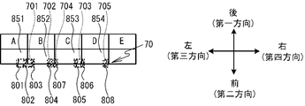
図9A~図9Cは、図7に示す紙媒体101の画像に、ストロークデータに基づく軌跡を重ね合わせた図の一部を記載したものである。具体例において、ユーザは、図9Aに示すストロークデータに基づく軌跡801~808の順番に、テキストを記入したとする。軌跡801~803は、テキスト「123」の「1」、「2」、及び「3」である。軌跡804は、テキスト「68」の「6」である。軌跡805,806は、テキスト「90」の「9」と「0」である。軌跡807は、テキスト68の「8」である。すなわち、テキスト68の「6」と「8」は連続する順番で記載されていない。軌跡808は、テキスト「2」である。
テキスト「123」の軌跡「1」、「2」、及び「3」は互いに所定距離以内にあるとする。テキスト「68」の軌跡「6」及び「8」は互いに所定距離以内にあるとする。テキスト「90」の軌跡「9」及び「0」は互いに所定距離以内であるとする。テキスト「123」、「68」、「90」、及び「2」の軌跡は、互いに所定距離より離れているとする。
図9Aにおいて、2番目の軌跡802「2」と1番目の軌跡「1」との間の距離は、所定距離以内である。このため、変数Nが2である場合、CPU41は、2番目の軌跡802と1番目の軌跡801との間の距離が所定距離以下であると判断する(S22:YES)。確認されていない軌跡があるので(S25:NO)、CPU41は、Nを3に設定し(S26)、処理をS22に戻す。CPU41は、3番目の軌跡803「3」と2番目の軌跡802「2」との間の距離が所定距離以内であると判断し(S22:YES)、Nを4に設定し(S25:NO、及びS26)、処理をS22に戻す。
CPU41は、CPU41は、4番目の軌跡804「6」と3番目の軌跡803「3」との間の距離が所定距離以内でないと判断する(S22:NO)。CPU41は、N-1番目までの軌跡を第Mグループ(Mは変数Mの値)としてグループ化する(S23)。具体例においては、図9Bに示すように、1番目の軌跡801「1」から3番目の軌跡803「3」までの軌跡を第1グループ701として、グループ化する(S23)。図9A~図9Cにおいては、グループ化されたグループが点線で囲まれて示されている。CPU41は、変数Mをインクリメントし(S24)、処理をS25に進める。
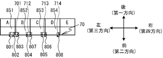
具体例においては、S22~S26の処理が繰り返されることで、図9Bに示すように、第2グループ702「6」、第3グループ703「90」、及び第4グループ704「8」がグループ化される。ユーザは、軌跡804「6」、軌跡805「9」、軌跡806「0」、及び軌跡807「8」の順に記載している。このため、S22~S26の処理の結果、軌跡804「6」と軌跡807「8」は、所定距離以内にあるにもかかわらず、異なるグループ702,704に分けられる。この異なるグループ702,704に分けられた軌跡804「6」と軌跡807「8」は、後述するS28~S33の処理によってグループ化される。
図8に示すように、CPU41は、全ての軌跡を確認した場合(S25:YES)、グループ化されていない軌跡をグループ化する(S27)。この結果、図9Bに示すように、軌跡808「2」が第5グループ705としてグループ化される。
次いで、CPU41は、変数Pを1に設定する(S28)。CPU41は、第Pグループを選択する。CPU41は、選択した第Pグループ内の軌跡と、他のグループ内の軌跡との間の距離が所定距離以下であるか否かを判断する(S29)。具体例において、変数Pが1の場合、CPU41は、第1グループ701内の軌跡801~803「123」と、他のグループ内の軌跡との間の距離は所定距離以下ではないと判断する(S29:NO)。次いで、CPU41は、S29において、全てのグループを選択したか否かを判断する(S32)。選択していないグループが残っている場合(S32:NO)、CPU41は、変数Pをインクリメントし(S33)、処理をS29に戻す。
変数Pが2の場合、図9Bに示す第2グループ702内の軌跡804「6」と、他のグループである第4グループ704内の軌跡807「8」との間の距離が、所定距離以下であると判断する(S29:YES)。CPU41は、S29において軌跡が所定距離以下であると判断した第Pグループと、他のグループとを、第Pグループとしてグループ化する(S30)。次いで、CPU41は、第Pグループ以降のグループ番号を振り直し、RAM43に記憶する(S31)。
具体例では、図9Cに示すように、図9Bに示す第2グループ702「6」と第4グループ704「8」とが新たな第2グループ712として、グループ化される(S30)。これによって、軌跡804「6」と軌跡807「8」とが1つのグループにまとめられる。そして、第3グループ703は、新たな第3グループ713と設定され、第5グループ705は、新たな第4グループ714に設定される(S31)。S31の実行後、CPU41は処理をS29に戻す。
図8に示すように、S29~S33が繰り返されると、図9Cに示すように、第1グループ701「123」、第2グループ712「68」、第3グループ713「90」、及び第4グループ714「2」が特定された状態となる。CPU41は、全てのグループを選択した場合(S32:YES)、処理をメイン処理に戻す。図5に示すように、CPU41は、補正処理を実行する(S14)。以下の説明においては、第1~第4グループ701,712,713,714を総称する場合、又はいずれかを特定しない場合、グループ70という場合がある。
図10を参照して、補正処理について説明する。補正処理は、紙媒体データに含まれる記入枠データに基づく記入枠85の内側に、グループ70を移動させる。本実施形態おいては、HDD42に記憶されている紙媒体データに含まれる記入枠データは、四角形の記入枠85の記入枠データである。以下の説明においては、図11Aに示すように、記入枠における一対の辺が対向する前後方向のうちの後方向を、「第一方向」という場合があり、第一方向の反対方向である前方向を「第二方向」という場合がある。また、前後方向と直交する左右方向のうちの左方向を「第三方向」という場合があり、第三方向の反対方向である右方向を「第四方向」という場合がある。
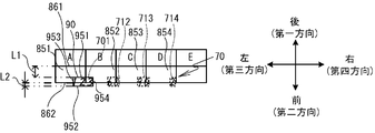
CPU41は、変数qを1に設定する(S41)。CPU41は、第qグループのグループ領域90(図11A参照)を取得する(S42)。グループ領域90とは、S13において特定されたグループ70を含む領域である。本実施形態においては、S41において取得されるグループ領域90は、四角形の領域である。具体例において、変数qが1である場合、図11Aに示すように、第1グループ701を含むグループ領域90が取得される。詳細には、第1グループ701に含まれる軌跡の座標のうち、最も第一方向側のY座標の位置が第一方向側の辺951の前後方向の位置とされ、最も第二方向側のY座標の位置が第二方向側の辺952の位置とされる。最も第三方向側のX座標の位置が第三方向側の辺953の位置とされ、最も第四方向側のX座標が第四方向側の辺954の位置とされる。辺951~954によって取り囲まれる領域が、グループ領域90として取得される。なお、図11Aにおいては、グループ領域90は実線の四角形で示されている。
図10に示すように、CPU41は、紙媒体データに含まれる少なくとも1の記入枠データに基づく記入枠85のうち、S42において取得したグループ領域90と領域が重なる記入枠85があるか否かを判断する(S43)、領域が重なる記入枠85がない場合(S43:NO)、CPU41は処理を後述するS51に進める。
領域が重なる記入枠85がある場合、CPU41は、紙媒体データに含まれる少なくとも1の記入枠データに基づく記入枠85のうち、S42において取得したグループ領域90と重なる領域が最も大きな記入枠85を選択する(S44)。具体例においては、図11Aにおいてグループ領域90と重なる領域が最も大きな記入枠851が選択される。
CPU41は、S44において選択された記入枠85内に、S42によってグループ領域90が取得されたグループ70を移動させる(S45~S50)。以下、詳細に説明する。
CPU41は、前後方向において、S42において取得したグループ領域90が、S44において選択した記入枠85内にあるか否かを判断する(S45)。具体例を用いて詳細に説明すると、CPU41は、図11Aに示すグループ領域90の辺951のY座標が、記入枠851の第一方向側の辺861のY座標以下であり、且つ、グループ領域90の辺952のY座標が、記入枠851の第二方向側の辺862のY座標以上であるか否かを判断する。
図10に示すように、前後方向において、S42において取得したグループ領域90が、S44において選択した記入枠85内にある場合(S45:YES)、CPU41は処理を後述するS48に進める。CPU41は、前後方向において、S42において取得したグループ領域90が、S44において選択した記入枠85内にない場合(S45:NO)、CPU41は、第一距離L1と、第二距離L2とを取得する(S46)。
図11Bに示すように、具体例の場合、第一距離L1は、S44において選択された記入枠851における第一方向側の辺861と、S42において取得されたグループ領域90の第一方向側の辺951の間の距離である。第二距離L2は、S44において選択された記入枠851における第二方向側の辺862と、S42において取得されたグループ領域90の第二方向側の辺952との間の距離である。
:
図10に示すように、CPU41は、S46において取得した第一距離L1と第二距離L2とのうち、小さい距離分、S42においてグループ領域90を取得したグループ701を前後方向に移動させる(S47)。具体例においては、図11Bに示すように、第一距離L1と第二距離L2とのうち小さい距離は、第二距離L2である。このため、CPU41は、第二距離L2分、第一方向にグループ701を移動させる。これによって、図11Cに示すように、前後方向において、グループ701が記入枠85の内側に位置する状態となる。
図10に示すように、CPU41は、S46において取得した第一距離L1と第二距離L2とのうち、小さい距離分、S42においてグループ領域90を取得したグループ701を前後方向に移動させる(S47)。具体例においては、図11Bに示すように、第一距離L1と第二距離L2とのうち小さい距離は、第二距離L2である。このため、CPU41は、第二距離L2分、第一方向にグループ701を移動させる。これによって、図11Cに示すように、前後方向において、グループ701が記入枠85の内側に位置する状態となる。
図10に示すように、CPU41は、左右方向において、S42において取得したグループ領域90が、S44において選択した記入枠85内にあるか否かを判断する(S48)。詳細に説明すると、CPU41は、図11Cに示すグループ領域90の第三方向側の辺953のX座標が、記入枠851の第三方向側の辺863のX座標以上であり、且つ、グループ領域90の第四方向側の辺954のX座標が、記入枠851の第四方向側の辺864のX座標以下であるか否かを判断する。
左右方向において、S42において取得したグループ領域90が、S44において選択した記入枠85内にある場合(S48:YES)、CPU41は処理をS51に進める。CPU41は、左右方向において、S42において取得したグループ領域90が、S44において選択した記入枠85内にない場合(S48:NO)、CPU41は、第三距離L3と、第四距離L4とを取得する(S49)。
図11Dに示すように、第三距離L3は、S44において選択された記入枠851における第三方向側の辺863と、S42において取得されたグループ領域90の第三方向側の辺953との間の距離である。第四距離L4は、S44において選択された記入枠851における第四方向側の辺864と、S42において取得されたグループ領域90の第四方向側の辺954との間の距離である。
:
図10に示すように、CPU41は、S46において取得した第三距離L3と第四距離L4とのうち、小さい距離分、S42においてグループ領域90を取得したグループ70を左右方向に移動させる(S50)。具体例においては、図11Dに示すように、第三距離L3と第四距離L4とのうち小さい距離は、第四距離L4である。このため、CPU41は、第四距離L4分、第三方向にグループ701を移動させる。これによって、図11Eに示すように、左右方向において、グループ701に含まれる軌跡が記入枠851の内側に位置する状態となる。
図10に示すように、CPU41は、S46において取得した第三距離L3と第四距離L4とのうち、小さい距離分、S42においてグループ領域90を取得したグループ70を左右方向に移動させる(S50)。具体例においては、図11Dに示すように、第三距離L3と第四距離L4とのうち小さい距離は、第四距離L4である。このため、CPU41は、第四距離L4分、第三方向にグループ701を移動させる。これによって、図11Eに示すように、左右方向において、グループ701に含まれる軌跡が記入枠851の内側に位置する状態となる。
図10に示すように、CPU41は、全てのグループ70について、S42においてグループ領域90を取得したか否かを判断する(S51)。グループ領域90を取得していないグループ領域90がある場合(S51:NO)、CPU41は、変数qをインクリメントし(S52)、処理をS42に戻す。S42~S52の処理が繰り返し実行されると、図12に示すように、第1~第4グループ701,712,713,714に含まれる軌跡が、夫々、記入枠851~854内に位置する状態となる。第1~第4グループ701,712,713,714に含まれる軌跡が、夫々、記入枠851~854内に位置する状態となったストロークデータは、HDD42に記憶される。
図10に示すように、全てのグループ70について、S42においてグループ領域90が取得された場合(S51:YES)、CPU41は、処理をメイン処理(図5参照)のS12に戻す。
以上のように、本実施形態のPC4は、紙媒体データに含まれる記入枠データに基づく記入枠85と、ストロークデータに基づく軌跡との位置に基づいて、ストロークデータに基づく軌跡の位置ずれを補正し、軌跡を記入枠85内に移動させることができる(図9A及び図12参照)。グループ領域90と重なる領域が最も大きな記入枠85以外の記入枠85にグループ70が移動される場合に比べて、ユーザが意図した記入枠85にグループ70を移動させることができる可能性が高くなる。従来のように、紙媒体上に基準マークを設ける必要がない。よって、基準マークを設けるためのスペースを紙媒体上に確保する必要がなく、紙媒体上のスペースを有効活用できる。ユーザが基準マークに沿って記入を行う手間を削減できるので、ユーザの利便性が向上する
PC4は、第一距離L1と第二距離L2とのうち小さい方の距離分、グループ70を前後方向に移動させ、且つ、第三距離L3と第四距離L4とのうち小さい方の距離分、グループ70を左右方向に移動させる。これによって、PC4は、記入枠85内にグループ70に含まれる軌跡を移動させることができる(S45~S50)。このため、PC4は、第一距離L1と第二距離L2とのうち大きい方の距離分、グループ70を前後方向に移動させ、且つ、第三距離L3と第四距離L4とのうち大きい方の距離分、グループ70を左右方向に移動させる場合に比べて、小さい移動量で、グループ70に含まれる軌跡を記入枠85内に移動させることができる。PC4は、S44において選択された記入枠85の中心と、S42において取得されたグループ領域90の中心とが同じ位置になるように、グループ70を移動させる場合に比べて、小さい移動量で、グループ70に含まれる軌跡を記入枠85内に移動させることができる。
上記実施形態において、PC4は本発明の「筆記データ処理装置」の一例である。電子ペン3は本発明の「筆記手段」の一例である。S12の処理を行うCPU41は本発明の「ストロークデータ取得手段」の一例である。S13の処理を行うCPU41は本発明の「グループ特定手段」の一例である。S42の処理を行うCPU41は本発明の「グループ領域取得手段」の一例である。S44の処理を行うCPU41は本発明の「記入枠選択手段」の一例である。S45~S50の処理を行うCPU41は本発明の「位置補正手段」の一例である。S46の処理を行うCPU41は本発明の「第一距離取得手段」の一例である。S47の処理を行うCPU41は本発明の「第一移動手段」の一例である。S49の処理を行うCPU41は本発明の「第二距離取得手段」の一例である。S50の処理を行うCPU41は本発明の「第二移動手段」の一例である。
本発明は上記の実施形態に限定されるものではなく、種々の変更が可能である。記入枠85内にグループ70を移動させる方法は、上記の実施形態に限定されない。CPU41は、S44において選択された記入枠85の中心と、S42において取得されたグループ領域90の中心とが同じ位置になるように、グループ70を移動させてもよい。以下、この変形例を第二実施形態として説明する。図13は、補正処理の変形例である。図13において、第一実施形態と同様の処理は、同じステップ番号で示し、詳細な説明は省略する。
図13に示すように、CPU41は、第一実施形態と同様に、S41~S44の処理を実行する。CPU41は、S44において選択された記入枠85の中心と、S42において取得されたグループ領域90の中心とが同じ位置になるように、グループ70を移動させる(S61及びS62)。詳細に説明する。図14Aは、図11Aと同様に、変数qが1である場合において、グループ701のグループ領域90が特定された図である。図13に示すように、CPU41は、S44において選択された記入枠851の中心871の座標と、S42において取得されたグループ領域90の中心971の座標との差を算出する(S61)。CPU41は、S62において算出した差の分だけ、グループ701を移動させる(S62)。これによって、図14Bに示すように、S44において選択された記入枠851の中心871と、S42において取得されたグループ領域90の中心971とが同じ位置になる。
図15に示すように、CPU41は、図10に示す場合と同様に、S51、S52の処理を実行し、処理をS42に戻す。CPU41は、S42~S44、S61、S62、S51、及びS52の処理を繰り返し、図14Cに示すように、各グループ70に含まれる軌跡を記入枠85内に移動させる。
第二実施形態の場合、図14Cに示すように、PC4は、第1~第4グループ701,712,713,714に含まれる軌跡を記入枠851~854に中心部に移動させることができる。この場合、グループ70に含まれる軌跡が記入枠85の隅に配置される場合に比べて、紙媒体データに基づく紙媒体101の画像に、ストロークデータに基づく軌跡を重ね合わせて表示又は印刷した場合の外観上の品質が向上する。第二実施形態において、S61及びS62の処理を行うCPU41は、本発明の「位置補正手段」の一例である。
上記実施形態においては、グループ70に含まれる軌跡のサイズの変更は行っていなかった。グループ70に含まれる軌跡のサイズを変更してもよい。以下、グループ70に含まれる軌跡のサイズを縮小する処理を含む補正処理を第三実施形態として説明する。図15は、補正処理の変形例である。図15において、第一実施形態及び第二実施形態と同様の処理は、同じステップ番号で示し、詳細な説明は省略する。
図15に示すように、CPU41は、上記実施形態と同様に、S41~S44の処理を実行する。CPU41は、S42において取得したグループ領域90のサイズと、S44において選択された記入枠85のサイズとを比較する。CPU41は、比較の結果、グループ領域90のサイズが記入枠85のサイズより大きいか否かを判断する(S71)。グループ領域90のサイズが記入枠85のサイズ以下である場合(S71:NO)、CPU41は、処理をS61に進める。
グループ領域90のサイズが、記入枠85のサイズより大きい場合(S71:YES)、グループ領域90のサイズを記入枠85のサイズ以下に縮小するように、グループ70に含まれる軌跡のサイズを変更する(S72)。
図16Aは、図11Aにおける第1グループ701に含まれる軌跡が、記入枠851のサイズより大きく記載された場合を示している。このグループを第1グループ721とする。変数qが1である場合、CPU41は、第1グループ721のグループ領域90のサイズが、記入枠851のサイズより大きいと判断する(S71:YES)。図16Bに示すように、CPU41は、グループ領域90のサイズを記入枠851のサイズ以下に縮小するように、第1グループ721に含まれる軌跡のサイズを変更する(S72)。
図15に示すように、S72の終了後、S42の場合と同様に、CPU41は、縮小後の軌跡のグループ70の第qグループ領域90を再取得する(S73)。CPU41は、上記実施形態と同様に、S61及びS62の処理を実行する。なお、S72において軌跡が縮小されている場合、S42において取得されたグループ領域90ではなく、S73において再取得されたグループ領域90(図16B参照)が参照されて、S61及びS62の処理が行われる。これによって、図16Cに示すように、CPU41は、第1グループ721に含まれる縮小後の軌跡を記入枠851に中心部に移動させる。
CPU41は、上記実施形態と同様に、S51及びS52の処理を実行後、処理をS42に戻す。CPU41は、S42~S44、S71~S73,S61、S62、S51、及びS52の処理を繰り返す。これによって、図16Dに示すように、各グループ70に含まれる軌跡が、記入枠851~854の内側に移動する。
第三実施形態の場合、図16Aに示すように、グループ領域90のサイズが記入枠85のサイズより大きくても、図16C及び図16Dに示すように、PC4は、サイズを変更して記入枠85内に収めることができる。また、例えば、紙媒体データに基づく紙媒体101の画像に、ストロークデータに基づく軌跡を重ね合わせて表示又は印刷した場合の外観上の品質が向上する。
グループに含まれる軌跡のサイズを拡大する処理を含む補正処理を、第四実施形態として説明する。図17は、補正処理の変形例である。図17において、第一~第三実施形態と同様の処理は、同じステップ番号で示し、詳細な説明は省略する。
図17に示すように、CPU41は、上記実施形態と同様に、S41~S44の処理を実行する。次いで、CPU41は、S42において取得したグループ領域90のサイズと、S44において選択された記入枠85のサイズとを比較する。CPU41は、比較の結果、グループ領域90のサイズが記入枠85のサイズより小さいか否かを判断する(S81)。グループ領域90のサイズが記入枠85のサイズ以上である場合(S81:NO)、CPU41は、処理をS61に進める。
グループ領域90のサイズが、記入枠85のサイズより小さい場合(S81:YES)、CPU41は、記入枠85のサイズ以下の範囲内において、グループ領域90のサイズを拡大するように、グループ70に含まれる軌跡のサイズを変更する(S82)。
図18Aは、図11Aと同様の図である。変数qが1である場合、CPU41は、第1グループ721のグループ領域90のサイズが、記入枠851のサイズより小さいと判断する(S81:YES)。図18Bに示すように、CPU41は、記入枠851のサイズ以下の範囲内において、グループ領域90のサイズを拡大するように第1グループ701に含まれる軌跡のサイズを変更する(S82)。
図17に示すように、S82の終了後、S42の場合と同様に、CPU41は、拡大後の軌跡のグループの第qグループ領域90を再取得する(S83)。次いで、CPU41は、図15の場合と同様に、S61及びS62の処理を実行する。なお、S82において軌跡が拡大されている場合、S42において取得されたグループ領域90ではなく、S83において再取得されたグループ領域90が参照されて、S61及びS62の処理が行われる。これによって、図18Cに示すように、CPU41は、グループ70に含まれる拡大後の軌跡を記入枠85に中心部に移動させる。
CPU41は、図15の場合と同様に、S51及びS52の処理を実行後、処理をS42に戻す。CPU41は、S42~S44、S81~S83,S61、S62、S51、及びS52の処理を繰り返す。これによって、図18Dに示すように、CPU41は、第1~第4グループ701,712,713,714に含まれる軌跡を拡大し、記入枠851~854の内側に移動させる。
第四実施形態の場合、図18A及び図18Dに示すように、記入枠85内に収まる範囲内で軌跡が拡大される。このため、例えば、紙媒体データの基づく紙媒体101の画像に、ストロークデータに基づく軌跡を重ね合わせて表示又は印刷した場合に、記入枠85内の軌跡の視認性を向上させることができる。また、外観上の品質が向上する。
第三実施形態及び第四実施形態のように、CPU41は、S42において取得したグループ領域90のサイズと、S44において選択した記入枠85のサイズとを比較する(S71及びS81)。CPU41は、比較の結果に応じて、S42においてグループ領域90を取得したグループ70に含まれる軌跡のサイズを変更する(S72及びS82)。グループ領域90のサイズと記入枠85のサイズとに応じて軌跡のサイズを変更することで、例えば、紙媒体データに基づく紙媒体101の画像に、ストロークデータに基づく軌跡を重ね合わせて表示又は印刷した場合の外観上の品質を向上させることができる。
第三実施形態及び第四実施形態において、S71(図15参照)及びS81(図17参照)の処理を行うCPU41は本発明の「比較手段」の一例である。S72(図15参照)及びS82(図17参照)の処理を行うCPU41は本発明の「サイズ補正手段」の一例である。
上記実施形態においては、CPU41によって記入枠85が選択されていた(S44)。CPU41は、記入枠85を選択した後、ユーザの指示に基づいて、選択する記入枠85を変更してもよい。CPU41は、1のグループ70を移動させた場合に同じ移動量分、他のグループ70も移動させてもよい。以下、これらの変形例を第五実施形態として説明する。図19において、第一~第四実施形態における処理と同様の処理は、同じステップ番号で示し、詳細な説明は省略する。
CPU41は、上記実施形態と同様に、S41~S44の処理を実行する。CPU41は、S42において取得したグループ領域90と重なる記入枠85がない場合(S43:NO)、S51及びS52の処理を実行し、処理をS42に戻す。
以下の説明においては、HDD42に記憶された紙媒体データに含まれる少なくとも1の記入枠データに基づく記入枠85のうち、S42において取得したグループ領域90と重なる領域が最も大きな記入枠85(すなわち、S44において選択された記入枠85)を第一の記入枠85という。また、第一の記入枠85とは異なる記入枠85を第二の記入枠85という。
CPU41は、S44を実行後、図21に示すように、HDD42に記憶された紙媒体データに基づく紙媒体101の画像と、ストロークデータに基づく軌跡とをディスプレイ48に表示する(S91)。図21においては、ディスプレイ48の図示は省略している。CPU41は、第一の記入枠85を、S91においてディスプレイ48に表示した紙媒体101の画像上に提示する(S92)。第一の記入枠85の提示の方法は限定されない。例えば、第一の記入枠85の周囲を点滅させてもよいし、第一の記入枠85の色を第二の記入枠85の色とは異なる色で表示してもよい。図21に示す例においては、第一の記入枠85(すなわち、記入枠851)を第二の記入枠85とは異なる色で表示している。
CPU41は、S91において表示した紙媒体101の画像において記入枠データに基づく記入枠85を選択する指示が入力されたか否かを判断する(S93)。すなわち、記入枠85を選択する指示が受け付けられたか否かを判断する。記入枠85を選択する指示は、ユーザによって入力部47(図2参照)が操作されることによってPC4に入力される。ユーザは、例えば、入力部47を操作して、ディスプレイ48に表示されるカーソル881(図21参照)を動かして、記入枠85を選択する。
記入枠85を選択する指示が受け付けられていない場合(S93:NO)、CPU41はS93を繰り返す。記入枠85を選択する指示が受け付けられた場合(S93:YES)、CPU41は、S93において受け付けた、第一の記入枠85と第二の記入枠85とのいずれかを選択する指示に基づき、記入枠85を選択する(S94)。図21に示す具体例においては、記入枠851の下側の記入枠855が選択されたとする。CPU91は、S94において選択された記入枠85内に、グループ領域90が収まっているか否かを判断する(S95)。
S94において選択された記入枠85内にグループ領域90が収まっていない場合(S95:NO)、図20に示すように、CPU41は、S45~S50の処理を実行する。すなわち、CPU41は、S94において選択した記入枠85内に、S42においてグループ領域90を取得したグループ70を移動させる。
CPU41は、S47及びS50において移動させたグループ70と同じ移動量分、他のグループ70を移動させる(S96)。すなわち、CPU41は、第一の記入枠85と第二の記入枠85とのうちS94において選択された記入枠85内にグループ70を移動するとともに、同じ移動量分、他のグループ70を移動する。具体例において、図22に示すように、軌跡「123」と同じ移動量分、軌跡「68」、「90」、「2」が移動される。これによって、軌跡「123」、「68」、「90」、「2」は、記入枠851~854の下側の記入枠855~858に移動する。次いで、図19に示すように、CPU41は補正処理を終了し、処理をメイン処理に戻す。
S94において選択された記入枠85内にグループ領域90が収まっている場合(S95:YES)、CPU41は、S61及びS62の処理を実行する。すなわち、CPU41は、S94において選択した記入枠85の中心と、S42において取得したグループ領域90の中心とが同じ位置となるように、S42においてグループ領域90を取得したグループ70を移動させる。
次いで、CPU41は、S62において移動させたグループ70と同じ移動量分、他のグループ70を移動させる(S97)。すなわち、CPU41は、第一の記入枠85と第二の記入枠85とのうちS94において選択された記入枠85内にグループ70を移動するとともに、同じ移動量分、他のグループ70を移動する。
図示しないが、例えば、軌跡「123」、「68」、「90」、「2」が、夫々、記入枠851~854内の収まっており、S93において第一の記入枠85である記入枠851が選択されたとする。この場合、CPU41は、軌跡「123」のグループ領域90が記入枠851に収まっていると判断し(S95:YES)、軌跡「123」が記入枠851の中心部に移動させ(S62)、同じ移動量分、他の軌跡「68」、「90」、「2」を移動させる。ユーザが紙媒体100に筆記した場合、記入枠851~854の中心に対する軌跡「123」、「68」、「90」、「2」の位置ずれは、互いに同じ距離になる傾向がある。このため、軌跡「123」が記入枠851の中心部に移動するのと同じ移動量分、他の軌跡「68」、「90」、「2」移動することで、軌跡「123」、「68」、「90」、「2」が、夫々、記入枠851~854の中心部に位置し易くなる。CPU41は補正処理を終了し、処理をメイン処理に戻す。
以上のように、第五実施形態においては、PC4は、軌跡を移動させる記入枠85をユーザに選択させることができる。ユーザは、所望の記入枠85に軌跡を移動させることができ、ユーザの利便性が向上する。また、記入枠85のうち、グループ領域90と重なる領域が最も大きな第一の記入枠85が、紙媒体101の画像上に提示される(S92)。このため、ユーザは、グループ領域90と重なる領域が最も大きな記入枠85を確認し易い。よって、記入枠85を選択する指示を入力する場合におけるユーザの利便性が向上する。
S13(図5参照)において特定された複数のグループ70のうち、S42(図19参照)においてグループ領域90が取得された1のグループ70が移動された移動量と同じ移動量分、他のグループ70が移動される(S96及びS97)。このため、全てのグループ70の夫々について、記入枠85と軌跡との位置に基づいて位置ずれを補正する場合に比べて、CPU41の処理の負荷を低減できる。
ユーザによって記入枠85が1回選択されるだけで(S93:YES)、全てのグループ70に含まれる軌跡が一括して移動する(S47、S50、S96、S62、及びS97)。このため、ユーザが何度も記入枠85を選択する場合に比べて、ユーザの利便性が向上する。
第五実施形態において、ディスプレイ48は本発明の「表示部」の一例である。S91の処理を行うCPU41は本発明の「表示制御手段」の一例である。S93の処理を行うCPU41は本発明の「受付手段」の一例である。S44、S91、及びS94の処理を行うCPU41は本発明の「記入枠選択手段」の一例である。S62、S97、S45~S50、及びS96の処理を行うCPU41は本発明の「位置補正手段」の一例である。
なお、第五実施形態においては、ユーザによって記入枠85が1回選択されるだけで(S93:YES)、全てのグループ70に含まれる軌跡(S47、S50、S96、S62、及びS97)が移動されている。同様に、上記第一~第四実施形態において、CPU41は、1のグループ70を移動させた場合に、同じ移動量分、他のグループ70を移動させてもよい。この場合においても、全てのグループ70の夫々について、記入枠85と軌跡との位置に基づいて位置ずれを補正する場合に比べて、CPU41の処理の負荷を低減できる。
なお、上記実施形態の種々の具体例においては、センサ基板7Lに対して、用紙700が右前方にずれた状態で配置されたために、ストロークデータに基づくテキスト「123」、「68」、「90」、「2」の軌跡が記入枠データに基づく記入枠851~854から右前方に位置ずれした状態となっていた。しかし、位置ずれする要因はこれに限定されない。例えば、ユーザが筆記する場合の電子ペン3の傾き具合に応じて、コイル32の位置が変わることで、位置ずれが発生する場合がある。
また、上記実施形態においては、記入枠85が四角形であったが、四角形とは異なる形状であってもよい。また、上記実施形態において、メイン処理は、PC4のCPU41によって実行されたが、これに限定されない。例えば、メイン処理は、読取装置2のCPU21によって実行されてもよい。この場合、HDD42及びRAM43の代わりにフラッシュROM22に、メイン処理を実行するためのプログラム等の種々のデータが記憶されてもよい。そして、CPU21は、補正後のストロークデータをPC4に送信してもよい。この場合、読取装置2が本発明の「筆記データ処理装置」の一例である。なお、読取装置2は、PC4ではなく、他の携帯端末等に接続され、携帯端末等のCPUが、メイン処理を実行してもよい。また、読取装置2にディスプレイを追加し、上記実施形態においてディスプレイ48に表示された画像を読取装置2のディスプレイに表示してもよい。
Claims (8)
- 紙媒体が載置される載置部上における、筆記手段の軌跡を示す複数のストロークデータを取得するストロークデータ取得手段と、
前記ストロークデータ取得手段によって取得された前記複数のストロークデータに基づく前記軌跡のうち、互いに所定距離以内にある前記軌跡をグループとして特定するグループ特定手段と、
前記グループ特定手段によって特定された前記グループを含む領域であるグループ領域を取得するグループ領域取得手段と、
記憶部に記憶された前記紙媒体に対応するデータである紙媒体データに含まれる少なくとも1の記入枠データに基づく記入枠のうち、前記グループ領域取得手段によって取得された前記グループ領域と重なる領域が最も大きな前記記入枠を選択する記入枠選択手段と、
前記記入枠選択手段によって選択された前記記入枠内に、前記グループ領域取得手段によって前記グループ領域が取得された前記グループを移動させる位置補正手段と
を備えたことを特徴とする筆記データ処理装置。 - 前記記憶部は、四角形の前記記入枠の前記記入枠データを記憶し、
前記グループ領域取得手段は、前記グループ特定手段によって特定された前記グループを含む四角形の領域を、前記グループ領域として取得し、
前記位置補正手段は、
前記記入枠における一対の辺が対向する対向方向のうちの第一方向側の辺と、前記グループ領域の前記第一方向側の辺との間の第一距離と、前記記入枠における前記第一方向の反対方向である第二方向側の辺と、前記グループ領域の前記第二方向側の辺との間の第二距離とを取得する第一距離取得手段と、
前記第一距離取得手段によって取得された前記第一距離と前記第二距離とのうち、小さい方の距離分、前記グループを前記対向方向に移動させる第一移動手段と、
前記記入枠における前記対向方向に直交する直交方向のうちの第三方向側の辺と、前記グループ領域の前記第三方向側の辺との間の第三距離と、前記記入枠における前記第三方向の反対方向である第四方向側の辺と、前記グループ領域の前記第四方向側の辺との間の第四距離とを取得する第二距離取得手段と、
前記第二距離取得手段によって取得された前記第三距離と前記第四距離とのうち、小さい方の距離分、前記グループを前記直交方向に移動させる第二移動手段と
を備えたことを特徴とする請求項1に記載の筆記データ処理装置。 - 前記位置補正手段は、前記記入枠選択手段によって選択された前記記入枠の中心と、前記グループ領域取得手段によって取得された前記グループ領域の中心とが同じ位置になるように、前記グループを移動させることを特徴とする請求項1に記載の筆記データ処理装置。
- 前記グループ領域取得手段によって取得された前記グループ領域のサイズと、前記記入枠選択手段によって選択された前記記入枠のサイズとを比較する比較手段と、
前記比較手段による比較の結果に応じて、前記グループ領域取得手段によって前記グループ領域が取得された前記グループに含まれる前記軌跡のサイズを変更するサイズ補正手段と
を備えたことを特徴とする請求項1から3のいずれかに記載の筆記データ処理装置。 - 前記サイズ補正手段は、前記比較手段による比較の結果、前記グループ領域取得手段によって取得された前記グループ領域のサイズが、前記記入枠選択手段によって選択された前記記入枠のサイズより大きい場合に、前記グループ領域のサイズを前記記入枠のサイズ以下に縮小するように、前記グループに含まれる前記軌跡のサイズを変更することを特徴とする請求項4に記載の筆記データ処理装置。
- 前記サイズ補正手段は、前記比較手段による比較の結果、前記グループ領域取得手段によって取得された前記グループ領域のサイズが、前記記入枠選択手段によって選択された前記記入枠のサイズより小さい場合に、前記記入枠のサイズ以下の範囲内において、前記グループ領域のサイズを拡大するように、前記グループに含まれる前記軌跡のサイズを変更することを特徴とする請求項4又は5に記載の筆記データ処理装置。
- 前記紙媒体データに基づく前記紙媒体の画像を表示部に表示する表示制御手段と、
前記表示制御手段によって表示された前記紙媒体の画像において前記記入枠データに基づく前記記入枠を選択する指示を受け付ける受付手段と
を備え、
前記記入枠選択手段は、前記記憶部に記憶された前記紙媒体データに含まれる少なくとも1の前記記入枠データに基づく前記記入枠のうち、前記グループ領域取得手段によって取得された前記グループ領域と重なる領域が最も大きな前記記入枠である第一記入枠を、前記表示制御手段によって前記表示部に表示された前記紙媒体の画像上に提示し、前記受付手段によって受け付けられた、前記第一記入枠と、前記第一記入枠とは異なる第二記入枠とのいずれかを選択する指示に基づき、前記記入枠を選択し、
前記位置補正手段は、前記記入枠選択手段によって選択された前記記入枠内に、前記グループ領域取得手段によって前記グループ領域が取得された前記グループを移動させることを特徴とする請求項1から6のいずれかに記載の筆記データ処理装置。 - 前記グループ特定手段は、複数の前記グループを特定し、
前記グループ領域取得手段は、前記グループ特定手段によって特定された複数の前記グループのうち、1の前記グループについて、前記グループ領域を取得し、
前記位置補正手段は、前記記入枠選択手段によって選択された前記記入枠内に、前記グループ領域取得手段によって前記グループ領域が取得された前記グループを移動させるとともに、移動させる前記グループと同じ移動量分、他の前記グループを移動させることを特徴とする請求項1から7のいずれかに記載の筆記データ処理装置。
Priority Applications (1)
| Application Number | Priority Date | Filing Date | Title |
|---|---|---|---|
| US15/665,825 US10551942B2 (en) | 2015-04-27 | 2017-08-01 | Writing data processing device for correcting position discrepancies in characters |
Applications Claiming Priority (2)
| Application Number | Priority Date | Filing Date | Title |
|---|---|---|---|
| JP2015090810A JP6432437B2 (ja) | 2015-04-27 | 2015-04-27 | 筆記データ処理装置 |
| JP2015-090810 | 2015-04-27 |
Related Child Applications (1)
| Application Number | Title | Priority Date | Filing Date |
|---|---|---|---|
| US15/665,825 Continuation US10551942B2 (en) | 2015-04-27 | 2017-08-01 | Writing data processing device for correcting position discrepancies in characters |
Publications (1)
| Publication Number | Publication Date |
|---|---|
| WO2016174952A1 true WO2016174952A1 (ja) | 2016-11-03 |
Family
ID=57199822
Family Applications (1)
| Application Number | Title | Priority Date | Filing Date |
|---|---|---|---|
| PCT/JP2016/058334 Ceased WO2016174952A1 (ja) | 2015-04-27 | 2016-03-16 | 筆記データ処理装置 |
Country Status (3)
| Country | Link |
|---|---|
| US (1) | US10551942B2 (ja) |
| JP (1) | JP6432437B2 (ja) |
| WO (1) | WO2016174952A1 (ja) |
Families Citing this family (2)
| Publication number | Priority date | Publication date | Assignee | Title |
|---|---|---|---|---|
| WO2019109218A1 (zh) * | 2017-12-04 | 2019-06-13 | 深圳市柔宇科技有限公司 | 手写输入装置 |
| US11301063B2 (en) * | 2018-07-18 | 2022-04-12 | John J. King, JR. | Smart pen device and method of implementing a smart pen device |
Citations (4)
| Publication number | Priority date | Publication date | Assignee | Title |
|---|---|---|---|---|
| JP2005038077A (ja) * | 2003-07-17 | 2005-02-10 | Hitachi Ltd | 筆記データ入力装置 |
| JP2005301652A (ja) * | 2004-04-12 | 2005-10-27 | Pentel Corp | 手書き筆跡入力装置用座標入力補正方法 |
| JP2007048217A (ja) * | 2005-08-12 | 2007-02-22 | Ricoh Co Ltd | 手書き情報入力装置 |
| JP2008015929A (ja) * | 2006-07-07 | 2008-01-24 | Univ Of Tokyo | 手書き入力処理装置、手書き入力処理方法、および手書き入力処理用プログラム |
Family Cites Families (6)
| Publication number | Priority date | Publication date | Assignee | Title |
|---|---|---|---|---|
| JPH10301701A (ja) | 1997-04-30 | 1998-11-13 | Casio Comput Co Ltd | 筆記データ入力装置およびそのプログラム記録媒体 |
| JP4171924B2 (ja) * | 2006-04-27 | 2008-10-29 | 富士通テン株式会社 | 機器制御システム |
| JP6119366B2 (ja) | 2013-03-27 | 2017-04-26 | ブラザー工業株式会社 | 補正装置 |
| JP2015162088A (ja) * | 2014-02-27 | 2015-09-07 | 株式会社東芝 | 電子機器、方法及びプログラム |
| US20150347364A1 (en) * | 2014-06-03 | 2015-12-03 | Lenovo (Singapore) Pte. Ltd. | Highlighting input area based on user input |
| US10489051B2 (en) * | 2014-11-28 | 2019-11-26 | Samsung Electronics Co., Ltd. | Handwriting input apparatus and control method thereof |
-
2015
- 2015-04-27 JP JP2015090810A patent/JP6432437B2/ja active Active
-
2016
- 2016-03-16 WO PCT/JP2016/058334 patent/WO2016174952A1/ja not_active Ceased
-
2017
- 2017-08-01 US US15/665,825 patent/US10551942B2/en not_active Expired - Fee Related
Patent Citations (4)
| Publication number | Priority date | Publication date | Assignee | Title |
|---|---|---|---|---|
| JP2005038077A (ja) * | 2003-07-17 | 2005-02-10 | Hitachi Ltd | 筆記データ入力装置 |
| JP2005301652A (ja) * | 2004-04-12 | 2005-10-27 | Pentel Corp | 手書き筆跡入力装置用座標入力補正方法 |
| JP2007048217A (ja) * | 2005-08-12 | 2007-02-22 | Ricoh Co Ltd | 手書き情報入力装置 |
| JP2008015929A (ja) * | 2006-07-07 | 2008-01-24 | Univ Of Tokyo | 手書き入力処理装置、手書き入力処理方法、および手書き入力処理用プログラム |
Also Published As
| Publication number | Publication date |
|---|---|
| JP6432437B2 (ja) | 2018-12-05 |
| US20170329424A1 (en) | 2017-11-16 |
| US10551942B2 (en) | 2020-02-04 |
| JP2016207092A (ja) | 2016-12-08 |
Similar Documents
| Publication | Publication Date | Title |
|---|---|---|
| US8840206B2 (en) | Nail print apparatus and printing control method | |
| US8994761B2 (en) | Information display control apparatus, information display control method, and storage medium storing information display control program | |
| US20170161869A1 (en) | Image display apparatus, control method therefor, and storage medium | |
| WO2014046302A1 (en) | Figure drawing apparatus, figure drawing method and recording medium on which figure drawing programs are recorded | |
| JP7773969B2 (ja) | 情報処理装置及び情報処理プログラム | |
| JP6119366B2 (ja) | 補正装置 | |
| US20130176214A1 (en) | Touch control method | |
| JP6432437B2 (ja) | 筆記データ処理装置 | |
| US9030708B2 (en) | Imposition apparatus, imposition method, and non-transitory computer-readable recording medium | |
| JP6171676B2 (ja) | 入力装置 | |
| JP4586539B2 (ja) | プレビュー装置およびプレビュー用プログラム並びにプレビュー方法 | |
| US20100271345A1 (en) | Electronic White Board Capable of Printing Partial Data Thereon | |
| EP2725461B1 (en) | Information management apparatus and storage medium storing information management program | |
| US20150077404A1 (en) | Paper Medium, Input Device, and Non-Transitory Computer-Readable Medium Storing Computer-Readable Instructions for Input Device | |
| JP7549869B2 (ja) | 加工ジョブ生成装置およびシート加工システム | |
| JP4887788B2 (ja) | 処理装置、プログラム及び電子ペン用帳票 | |
| EP2793108B1 (en) | Information processing apparatus and recording medium storing program | |
| JP2015056051A (ja) | 筆記データ処理装置 | |
| US11373072B2 (en) | Information processing device and information processing method for correcting orientation of images | |
| JP2005301652A (ja) | 手書き筆跡入力装置用座標入力補正方法 | |
| CN114089842B (zh) | 电磁笔的倾斜方向判断和游标位置计算的方法及显示装置 | |
| JP4337666B2 (ja) | 手書き筆跡入力装置用マウス用カーソルの表示方法 | |
| JP6268056B2 (ja) | 筆記データ処理プログラム、及び、筆記データ処理装置 | |
| CN103809775A (zh) | 电子设备以及信息处理方法 | |
| JP2015114772A (ja) | 表示制御装置 |
Legal Events
| Date | Code | Title | Description |
|---|---|---|---|
| 121 | Ep: the epo has been informed by wipo that ep was designated in this application |
Ref document number: 16786229 Country of ref document: EP Kind code of ref document: A1 |
|
| NENP | Non-entry into the national phase |
Ref country code: DE |
|
| 122 | Ep: pct application non-entry in european phase |
Ref document number: 16786229 Country of ref document: EP Kind code of ref document: A1 |