WO2016174880A1 - 濾過装置、プリーツフィルターおよびバラスト水の処理方法 - Google Patents
濾過装置、プリーツフィルターおよびバラスト水の処理方法 Download PDFInfo
- Publication number
- WO2016174880A1 WO2016174880A1 PCT/JP2016/050650 JP2016050650W WO2016174880A1 WO 2016174880 A1 WO2016174880 A1 WO 2016174880A1 JP 2016050650 W JP2016050650 W JP 2016050650W WO 2016174880 A1 WO2016174880 A1 WO 2016174880A1
- Authority
- WO
- WIPO (PCT)
- Prior art keywords
- filter
- water
- pleated filter
- peak
- treated
- Prior art date
- Legal status (The legal status is an assumption and is not a legal conclusion. Google has not performed a legal analysis and makes no representation as to the accuracy of the status listed.)
- Ceased
Links
Images


Classifications
-
- B—PERFORMING OPERATIONS; TRANSPORTING
- B01—PHYSICAL OR CHEMICAL PROCESSES OR APPARATUS IN GENERAL
- B01D—SEPARATION
- B01D33/00—Filters with filtering elements which move during the filtering operation
- B01D33/06—Filters with filtering elements which move during the filtering operation with rotary cylindrical filtering surfaces, e.g. hollow drums
- B01D33/073—Filters with filtering elements which move during the filtering operation with rotary cylindrical filtering surfaces, e.g. hollow drums arranged for inward flow filtration
-
- B—PERFORMING OPERATIONS; TRANSPORTING
- B01—PHYSICAL OR CHEMICAL PROCESSES OR APPARATUS IN GENERAL
- B01D—SEPARATION
- B01D33/00—Filters with filtering elements which move during the filtering operation
- B01D33/27—Filters with filtering elements which move during the filtering operation with rotary filtering surfaces, which are neither cylindrical nor planar, e.g. helical surfaces
-
- B—PERFORMING OPERATIONS; TRANSPORTING
- B01—PHYSICAL OR CHEMICAL PROCESSES OR APPARATUS IN GENERAL
- B01D—SEPARATION
- B01D33/00—Filters with filtering elements which move during the filtering operation
- B01D33/70—Filters with filtering elements which move during the filtering operation having feed or discharge devices
- B01D33/72—Filters with filtering elements which move during the filtering operation having feed or discharge devices for feeding
-
- B—PERFORMING OPERATIONS; TRANSPORTING
- B63—SHIPS OR OTHER WATERBORNE VESSELS; RELATED EQUIPMENT
- B63J—AUXILIARIES ON VESSELS
- B63J4/00—Arrangements of installations for treating ballast water, waste water, sewage, sludge, or refuse, or for preventing environmental pollution not otherwise provided for
- B63J4/002—Arrangements of installations for treating ballast water, waste water, sewage, sludge, or refuse, or for preventing environmental pollution not otherwise provided for for treating ballast water
-
- C—CHEMISTRY; METALLURGY
- C02—TREATMENT OF WATER, WASTE WATER, SEWAGE, OR SLUDGE
- C02F—TREATMENT OF WATER, WASTE WATER, SEWAGE, OR SLUDGE
- C02F1/00—Treatment of water, waste water, or sewage
- C02F1/001—Processes for the treatment of water whereby the filtration technique is of importance
- C02F1/004—Processes for the treatment of water whereby the filtration technique is of importance using large scale industrial sized filters
-
- C—CHEMISTRY; METALLURGY
- C02—TREATMENT OF WATER, WASTE WATER, SEWAGE, OR SLUDGE
- C02F—TREATMENT OF WATER, WASTE WATER, SEWAGE, OR SLUDGE
- C02F1/00—Treatment of water, waste water, or sewage
- C02F1/30—Treatment of water, waste water, or sewage by irradiation
- C02F1/32—Treatment of water, waste water, or sewage by irradiation with ultraviolet light
-
- C—CHEMISTRY; METALLURGY
- C02—TREATMENT OF WATER, WASTE WATER, SEWAGE, OR SLUDGE
- C02F—TREATMENT OF WATER, WASTE WATER, SEWAGE, OR SLUDGE
- C02F1/00—Treatment of water, waste water, or sewage
- C02F1/46—Treatment of water, waste water, or sewage by electrochemical methods
-
- B—PERFORMING OPERATIONS; TRANSPORTING
- B01—PHYSICAL OR CHEMICAL PROCESSES OR APPARATUS IN GENERAL
- B01D—SEPARATION
- B01D2201/00—Details relating to filtering apparatus
- B01D2201/12—Pleated filters
-
- B—PERFORMING OPERATIONS; TRANSPORTING
- B01—PHYSICAL OR CHEMICAL PROCESSES OR APPARATUS IN GENERAL
- B01D—SEPARATION
- B01D2201/00—Details relating to filtering apparatus
- B01D2201/28—Position of the filtering element
- B01D2201/282—Filtering elements with a horizontal rotation or symmetry axis
-
- B—PERFORMING OPERATIONS; TRANSPORTING
- B01—PHYSICAL OR CHEMICAL PROCESSES OR APPARATUS IN GENERAL
- B01D—SEPARATION
- B01D2201/00—Details relating to filtering apparatus
- B01D2201/32—Flow characteristics of the filter
- B01D2201/325—Outward flow filtration
-
- C—CHEMISTRY; METALLURGY
- C02—TREATMENT OF WATER, WASTE WATER, SEWAGE, OR SLUDGE
- C02F—TREATMENT OF WATER, WASTE WATER, SEWAGE, OR SLUDGE
- C02F2103/00—Nature of the water, waste water, sewage or sludge to be treated
- C02F2103/008—Originating from marine vessels, ships and boats, e.g. bilge water or ballast water
Definitions
- a discharge flow path for discharging to the outside wherein the pleat filter is in one direction around the axis Is configured to rotate, the ridges the rotational direction of the plurality of peaks of the pleats filter is a filtration apparatus, which is curved in a shape bulging in the opposite direction.
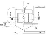
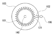
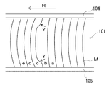
- FIG. 3 is a diagram schematically showing a configuration of a horizontal AA cross section in the filtration device of FIG. 2. It is the schematic diagram which expanded a part of side surface of a pleat filter, and is a figure which shows the state which the pleat curves to the right. It is the schematic diagram which expanded a part of side surface of a pleat filter, and is a figure which shows the state which the pleat curves to the left.
- the pleated filter becomes large, and its prevention of breakage is particularly important.
- a valve or the like is not shown in the discharge channel 108, but equipment necessary for maintenance and flow rate adjustment can be provided.
- the filtered water filtered by the pleated filter 101 is guided to the filtered water flow path 107 through the water intake hole 141 provided in the central pipe 140 inside the filter and flows out of the case.
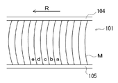
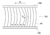
- An arrow R indicates the direction of rotation of the pleated filter 101.
- a treated water nozzle 102 is provided opposite to the side surface of the pleated filter 101, and the treated water is ejected from the nozzle port 121 toward the pleated filter 101.
- the flow of water to be treated is given in the order of e ⁇ d ⁇ c ⁇ b ⁇ a. “The ridge lines of the plurality of peaks are curved in a shape that swells in the direction opposite to the rotation direction” as shown in FIG.
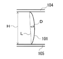
- the magnitude of the curvature of the pleated filter is determined by the relationship between the distance D between the straight line connecting both ends of the peak and the central part of the peak and the linear distance H connecting both ends of the peak. > 0.004 is preferred. In the case of D / H ⁇ 0.004, the action by the water to be treated, which will be described later, is the same as in the case of the reverse curve, and the peak portion is easily damaged.
- FIG. 6 is a diagram for explaining the definition of the magnitude of curvature.
- FIG. 6 is a diagram depicting only one ridge line of the pleated filter 101 fixed to the upper and lower lid members 104 and 105. The distance between the upper and lower lid members 104 and 105 is H.
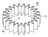
- the pleat filter demonstrated by the above filtration apparatus can be used as the filtration membrane used for the said filtration apparatus independently, and in many cases, the pleat filter as an exchange member. That is, the pleated filter is a pleated filter used in a filtration device, and when a cylindrical side surface is observed from a direction perpendicular to the axis, a plurality of ridge lines of the ridges are relative to a straight line connecting both ends of the ridges.
- the pleated filter is curved in the same direction.
- it is also preferable from the viewpoint of convenience of replacement such that the pleat filter is handled as a pleated filter cartridge in which the upper and lower sides of the pleated filter are sealed by respective lid members.
- the above-described filtration device is mounted in the hull, seawater obtained from the outside of the hull is used as water to be treated, and the filtered water treated by the filtration device is further killed Can be provided, and a ballast water treatment method and a ballast water treatment system can be provided.
- FIG. 9 is a schematic view of this state viewed from the side of the pleated filter.
- the solid line indicates the peak M and the dotted line indicates the valley V.
- the pleated filter 101 has its upper and lower ends fixed by lid members 104 and 105, respectively. Therefore, when the water to be treated flows between the pleats, the central portion of the pleated filter 101 is opened larger, and the vicinity of the upper and lower end portions of the pleated filter 101 is slightly opened.
- the entire fold is bent in the same direction, so-called bending.
- bending By forming this in an annular shape, the folds are bent in the same direction over the entire circumferential direction.
- a curve can be formed by using such a bend.
- a curved shape may be intentionally formed by using a curved mold when folding, and the method is not particularly limited.
- FIG. 10 shows a state where the bending direction of the mountain portion is a shape that swells in the direction opposite to the rotation direction.
- the portion where the deformation of the pleat peak portion concentrates differs depending on the relationship between the direction of bending and the rotation direction, a difference occurs in the damage mode in the peak portion of the filter base material. If the ridge is curved in a direction that swells in the direction opposite to the rotational direction, damage that occurs in the ridge is likely to occur in the center, and if it is swelled in the rotational direction, the damage is near the upper and lower ends. It is easy to generate.
- the used pleat filter has an outer diameter (circumferential diameter of the crest of the cylinder) of 700 mm, an axial length of 378 mm, a pleat depth of 70 mm, and a pleat count of 450. Furthermore, operating conditions, the jet flux 6.9 m / sec, when the filtration flow rate 71.7m 3 /, is when the drainage flow rate 14.3m 3 /.
- the filter substrate used is a polyethylene terephthalate nonwoven fabric (trade name: Axter G2260-1S BK0 manufactured by Toray), and the peaks and valleys are reinforced with resin.
Landscapes
- Chemical & Material Sciences (AREA)
- Engineering & Computer Science (AREA)
- Chemical Kinetics & Catalysis (AREA)
- Environmental & Geological Engineering (AREA)
- Water Supply & Treatment (AREA)
- Organic Chemistry (AREA)
- Life Sciences & Earth Sciences (AREA)
- Hydrology & Water Resources (AREA)
- Health & Medical Sciences (AREA)
- Toxicology (AREA)
- General Health & Medical Sciences (AREA)
- Public Health (AREA)
- Combustion & Propulsion (AREA)
- Mechanical Engineering (AREA)
- Ocean & Marine Engineering (AREA)
- General Chemical & Material Sciences (AREA)
- Electrochemistry (AREA)
- Physical Water Treatments (AREA)
- Separation Using Semi-Permeable Membranes (AREA)
- Filtering Materials (AREA)
- Filtration Of Liquid (AREA)
Abstract
Description
そこで、本発明は、使用による劣化や破損を防止し、長期間安定して使用することが可能なプリーツフィルター、およびそれを用いた濾過装置を提供することを目的とする。
11 フィルター基材
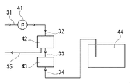
41 ポンプ
42 濾過装置
43 殺滅装置
44 タンク
31、32、33、34、35 配管
102 被処理水ノズル
103 ケース
104、105 蓋部材
106 被処理水流路
107 濾過水流路
108 排出流路
121 ノズル口
131 外筒部
132 蓋部
133 底部
140 中心配管
141 取水穴
190 モーター
以下、本願発明の実施形態としてのプリーツフィルターおよびそれを濾過膜として用いた濾過装置の構成を、以下に図面を参照しつつ説明する。なお、本発明はこれらの例示に限定されるものではなく、特許請求の範囲によって示され、特許請求の範囲と均等の意味および範囲内でのすべての変更が含まれることが意図される。
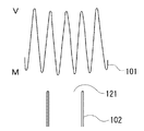
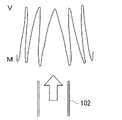
図7から図11を用いて、プリーツフィルターの破損と湾曲の関係について説明する。再び図2および図3を参照して説明すると、濾過装置において円筒状のプリーツフィルター101は、ケース103の中で回転しつつ円筒外部から内部に向けての濾過を行うために用いられる。ここで、フィルターの外表面は、ノズル口121から噴出する被処理水が流れることによって洗浄される。このようにプリーツフィルター101に被処理水ノズル102が向かい合っている部分の水平断面を拡大した状態を模式的に図7に示す。図7において、Mがプリーツフィルター101の外側である山部、Vが内側である谷部である。図8を参照して、被処理水ノズル102のノズル口121から被処理水が太矢印のように噴出すると、その被処理水によってプリーツフィルター101は開かれる。この状態をプリーツフィルターの側面から見た模式図が図9である。図9において実線が山部M、点線が谷部Vを示す。プリーツフィルター101はその上下端を蓋部材104および105によってそれぞれ固定されている。そのため、被処理水がプリーツ間に流入することによって、プリーツフィルター101の中央部はより大きく開かれ、プリーツフィルター101の上下両端部近傍は僅かしか開かない。
湾曲方向によるフィルター破損の違いを検証するため、複数のプリーツフィルターを準備して濾過装置に組み入れ、濾過実験をおこなった。用いたプリーツフィルターの外径(円筒山部の円周直径)は700mm、軸方向長さ378mm、プリーツ深さ70mm、プリーツ数450折である。また、運転条件は、噴流流束6.9m/秒、ろ過流量71.7m3/時、排水流量14.3m3/時である。記載使用したフィルター基材はポリエチレンテレフタレート製不織布(商品名:東レ製 アクスターG2260-1S BK0)であり、山部および谷部は樹脂による補強を施している。

Claims (5)
- フィルター基材が山部と谷部を繰り返すように折り目を有し、前記折り目の稜線方向を軸方向として前記山部が半径方向外側に位置する円筒形状としたプリーツフィルターを備え、
前記プリーツフィルターの外周面に向けて被処理水を流出する被処理水ノズルと、前記プリーツフィルターを囲むように設けられ前記被処理水ノズルのノズルロを内部に備えた外筒部を有するケースと、前記プリーツフィルターを透過した濾過水を前記プリーツフィルターの円筒内部から前記ケースの外部へ導出する濾過水流路と、前記プリーツフィルターで濾過されなかった排出水を前記ケースの外部へ排出する排出流路とを備えた濾過装置であって、
前記プリーツフィルターは前記軸を中心に一の方向に回転するように構成されており、前記プリーツフィルターの複数の山部の稜線が前記回転方向とは逆方向に膨らむ形状に湾曲している濾過装置。 - 前記湾曲の大きさは、前記山部の両端部を結ぶ直線と前記山部の中央部との距離Dと、前記山部の両端部を結ぶ直線距離Hとの関係が、D/H>0.004である、請求項1に記載の濾過装置。
- 前記フィルター基材はポリエチレンテレフタレート製不織布である、請求項1または請求項2に記載の濾過装置。
- 請求項1から請求項3のいずれか1項に記載の濾過装置に用いられるプリーツフィルターであって、
前記円筒形状の側面を軸直角方向から観察した場合に、複数の前記山部の稜線が前記山部の両端部を結ぶ直線に対して同一方向に湾曲している、プリーツフィルター。 - 請求項1から請求項3のいずれか1項に記載の濾過装置を船体内に搭載し、船体外部から取得した海水を被処理水として用い、前記濾過装置により処理された濾過水にさらに殺滅処理を加えた後に、バラスト水として船体内に貯留するバラスト水の処理方法。
Priority Applications (3)
| Application Number | Priority Date | Filing Date | Title |
|---|---|---|---|
| KR1020167035286A KR20170141106A (ko) | 2015-04-30 | 2016-01-12 | 여과 장치, 플리츠 필터 및 밸러스트수의 처리 방법 |
| CN201680001879.9A CN106536015A (zh) | 2015-04-30 | 2016-01-12 | 过滤装置、折叠过滤器和处理压载水的方法 |
| US15/318,048 US20170107119A1 (en) | 2015-04-30 | 2016-01-12 | Filtering device, pleated filter, and method for treating ballast water |
Applications Claiming Priority (2)
| Application Number | Priority Date | Filing Date | Title |
|---|---|---|---|
| JP2015092497A JP2016209781A (ja) | 2015-04-30 | 2015-04-30 | 濾過装置、プリーツフィルターおよびバラスト水の処理方法 |
| JP2015-092497 | 2015-04-30 |
Publications (1)
| Publication Number | Publication Date |
|---|---|
| WO2016174880A1 true WO2016174880A1 (ja) | 2016-11-03 |
Family
ID=57199194
Family Applications (1)
| Application Number | Title | Priority Date | Filing Date |
|---|---|---|---|
| PCT/JP2016/050650 Ceased WO2016174880A1 (ja) | 2015-04-30 | 2016-01-12 | 濾過装置、プリーツフィルターおよびバラスト水の処理方法 |
Country Status (5)
| Country | Link |
|---|---|
| US (1) | US20170107119A1 (ja) |
| JP (1) | JP2016209781A (ja) |
| KR (1) | KR20170141106A (ja) |
| CN (1) | CN106536015A (ja) |
| WO (1) | WO2016174880A1 (ja) |
Families Citing this family (1)
| Publication number | Priority date | Publication date | Assignee | Title |
|---|---|---|---|---|
| CN107694341A (zh) * | 2017-09-27 | 2018-02-16 | 江苏新宇天成环保有限公司 | 一种星型固液分滤机及分滤方法 |
Citations (3)
| Publication number | Priority date | Publication date | Assignee | Title |
|---|---|---|---|---|
| US20060151383A1 (en) * | 2005-01-12 | 2006-07-13 | Aaf-Mcquay Inc. | Pleated corrugated media and method of making |
| JP2012096231A (ja) * | 2005-03-04 | 2012-05-24 | Pall Corp | 波形流体処理パック |
| JP2013173093A (ja) * | 2012-02-24 | 2013-09-05 | Sumitomo Electric Ind Ltd | 船舶用バラスト水の処理システム |
Family Cites Families (3)
| Publication number | Priority date | Publication date | Assignee | Title |
|---|---|---|---|---|
| GB1056263A (en) * | 1962-10-02 | 1967-01-25 | Pierre Lucien Theobald | Filtration units |
| KR101176713B1 (ko) * | 2007-08-30 | 2012-08-23 | 고쿠리쓰다이가쿠호진 규슈다이가쿠 | 여과장치 및 여과방법 |
| JP4835785B2 (ja) * | 2010-02-25 | 2011-12-14 | 住友電気工業株式会社 | 船舶用バラスト水の処理装置 |
-
2015
- 2015-04-30 JP JP2015092497A patent/JP2016209781A/ja not_active Withdrawn
-
2016
- 2016-01-12 CN CN201680001879.9A patent/CN106536015A/zh active Pending
- 2016-01-12 US US15/318,048 patent/US20170107119A1/en not_active Abandoned
- 2016-01-12 WO PCT/JP2016/050650 patent/WO2016174880A1/ja not_active Ceased
- 2016-01-12 KR KR1020167035286A patent/KR20170141106A/ko not_active Withdrawn
Patent Citations (3)
| Publication number | Priority date | Publication date | Assignee | Title |
|---|---|---|---|---|
| US20060151383A1 (en) * | 2005-01-12 | 2006-07-13 | Aaf-Mcquay Inc. | Pleated corrugated media and method of making |
| JP2012096231A (ja) * | 2005-03-04 | 2012-05-24 | Pall Corp | 波形流体処理パック |
| JP2013173093A (ja) * | 2012-02-24 | 2013-09-05 | Sumitomo Electric Ind Ltd | 船舶用バラスト水の処理システム |
Also Published As
| Publication number | Publication date |
|---|---|
| US20170107119A1 (en) | 2017-04-20 |
| KR20170141106A (ko) | 2017-12-22 |
| CN106536015A (zh) | 2017-03-22 |
| JP2016209781A (ja) | 2016-12-15 |
Similar Documents
| Publication | Publication Date | Title |
|---|---|---|
| JP6019909B2 (ja) | 液体濾過装置およびそれを用いたバラスト水処理装置 | |
| WO2015111496A1 (ja) | プリーツフィルター、それを用いたバラスト水処理装置およびバラスト水の処理方法 | |
| EP2939724A1 (en) | Ballast water treatment device and back-washing method for ballast water treatment device | |
| JP5811162B2 (ja) | プリーツフィルター、それを用いたバラスト水処理装置およびバラスト水の処理方法 | |
| JP5982878B2 (ja) | 船舶用バラスト水の処理システムおよび船舶用バラスト水の処理方法 | |
| CN105246570B (zh) | 过滤装置、压载水处理方法以及使用过滤装置的压载水处理设备 | |
| KR20140138008A (ko) | 선박용 밸러스트수의 처리 시스템 | |
| WO2016031388A1 (ja) | バラスト水処理装置およびバラスト水の処理方法 | |
| JP6051669B2 (ja) | バラスト水処理装置およびフィルターカートリッジ | |
| JP2016209781A (ja) | 濾過装置、プリーツフィルターおよびバラスト水の処理方法 | |
| JP5765322B2 (ja) | プリーツフィルター、それを用いたバラスト水処理装置、バラスト水の処理方法、およびプリーツフィルターの製造方法 | |
| JP2015009170A (ja) | プリーツフィルター、それを用いたバラスト水処理装置およびバラスト水の処理方法 | |
| JP5716931B2 (ja) | プリーツフィルター、それを用いたバラスト水処理装置およびバラスト水の処理方法 | |
| JP6019722B2 (ja) | 液体濾過装置およびバラスト水処理装置 | |
| JP2013091017A (ja) | 液体濾過装置およびバラスト水処理装置 | |
| WO2015072381A1 (ja) | プリーツフィルター、それを用いたバラスト水処理装置およびバラスト水の処理方法 |
Legal Events
| Date | Code | Title | Description |
|---|---|---|---|
| WWE | Wipo information: entry into national phase |
Ref document number: 15318048 Country of ref document: US |
|
| 121 | Ep: the epo has been informed by wipo that ep was designated in this application |
Ref document number: 16786157 Country of ref document: EP Kind code of ref document: A1 |
|
| ENP | Entry into the national phase |
Ref document number: 20167035286 Country of ref document: KR Kind code of ref document: A |
|
| REEP | Request for entry into the european phase |
Ref document number: 2016786157 Country of ref document: EP |
|
| WWE | Wipo information: entry into national phase |
Ref document number: 2016786157 Country of ref document: EP |
|
| NENP | Non-entry into the national phase |
Ref country code: DE |