WO2016174872A1 - 粒子線治療システム、粒子線治療用管理システム及び方法 - Google Patents
粒子線治療システム、粒子線治療用管理システム及び方法 Download PDFInfo
- Publication number
- WO2016174872A1 WO2016174872A1 PCT/JP2016/002212 JP2016002212W WO2016174872A1 WO 2016174872 A1 WO2016174872 A1 WO 2016174872A1 JP 2016002212 W JP2016002212 W JP 2016002212W WO 2016174872 A1 WO2016174872 A1 WO 2016174872A1
- Authority
- WO
- WIPO (PCT)
- Prior art keywords
- treatment
- irradiation
- treatment plan
- plan data
- dose distribution
- Prior art date
- Legal status (The legal status is an assumption and is not a legal conclusion. Google has not performed a legal analysis and makes no representation as to the accuracy of the status listed.)
- Ceased
Links
Images


Classifications
-
- A—HUMAN NECESSITIES
- A61—MEDICAL OR VETERINARY SCIENCE; HYGIENE
- A61N—ELECTROTHERAPY; MAGNETOTHERAPY; RADIATION THERAPY; ULTRASOUND THERAPY
- A61N5/00—Radiation therapy
- A61N5/10—X-ray therapy; Gamma-ray therapy; Particle-irradiation therapy
- A61N5/103—Treatment planning systems
-
- A—HUMAN NECESSITIES
- A61—MEDICAL OR VETERINARY SCIENCE; HYGIENE
- A61N—ELECTROTHERAPY; MAGNETOTHERAPY; RADIATION THERAPY; ULTRASOUND THERAPY
- A61N5/00—Radiation therapy
- A61N5/10—X-ray therapy; Gamma-ray therapy; Particle-irradiation therapy
- A61N5/103—Treatment planning systems
- A61N5/1039—Treatment planning systems using functional images, e.g. PET or MRI
-
- A—HUMAN NECESSITIES
- A61—MEDICAL OR VETERINARY SCIENCE; HYGIENE
- A61N—ELECTROTHERAPY; MAGNETOTHERAPY; RADIATION THERAPY; ULTRASOUND THERAPY
- A61N5/00—Radiation therapy
- A61N5/10—X-ray therapy; Gamma-ray therapy; Particle-irradiation therapy
- A61N5/1048—Monitoring, verifying, controlling systems and methods
-
- A—HUMAN NECESSITIES
- A61—MEDICAL OR VETERINARY SCIENCE; HYGIENE
- A61N—ELECTROTHERAPY; MAGNETOTHERAPY; RADIATION THERAPY; ULTRASOUND THERAPY
- A61N5/00—Radiation therapy
- A61N5/10—X-ray therapy; Gamma-ray therapy; Particle-irradiation therapy
- A61N5/1048—Monitoring, verifying, controlling systems and methods
- A61N5/1064—Monitoring, verifying, controlling systems and methods for adjusting radiation treatment in response to monitoring
- A61N5/1065—Beam adjustment
-
- G—PHYSICS
- G06—COMPUTING OR CALCULATING; COUNTING
- G06T—IMAGE DATA PROCESSING OR GENERATION, IN GENERAL
- G06T15/00—Three-dimensional [3D] image rendering
- G06T15/005—General purpose rendering architectures
-
- G—PHYSICS
- G06—COMPUTING OR CALCULATING; COUNTING
- G06T—IMAGE DATA PROCESSING OR GENERATION, IN GENERAL
- G06T7/00—Image analysis
- G06T7/70—Determining position or orientation of objects or cameras
- G06T7/73—Determining position or orientation of objects or cameras using feature-based methods
- G06T7/74—Determining position or orientation of objects or cameras using feature-based methods involving reference images or patches
-
- H—ELECTRICITY
- H04—ELECTRIC COMMUNICATION TECHNIQUE
- H04N—PICTORIAL COMMUNICATION, e.g. TELEVISION
- H04N13/00—Stereoscopic video systems; Multi-view video systems; Details thereof
- H04N13/20—Image signal generators
- H04N13/275—Image signal generators from three-dimensional [3D] object models, e.g. computer-generated stereoscopic image signals
-
- A—HUMAN NECESSITIES
- A61—MEDICAL OR VETERINARY SCIENCE; HYGIENE
- A61N—ELECTROTHERAPY; MAGNETOTHERAPY; RADIATION THERAPY; ULTRASOUND THERAPY
- A61N5/00—Radiation therapy
- A61N5/10—X-ray therapy; Gamma-ray therapy; Particle-irradiation therapy
- A61N5/1048—Monitoring, verifying, controlling systems and methods
- A61N5/1049—Monitoring, verifying, controlling systems and methods for verifying the position of the patient with respect to the radiation beam
- A61N2005/1061—Monitoring, verifying, controlling systems and methods for verifying the position of the patient with respect to the radiation beam using an x-ray imaging system having a separate imaging source
-
- A—HUMAN NECESSITIES
- A61—MEDICAL OR VETERINARY SCIENCE; HYGIENE
- A61N—ELECTROTHERAPY; MAGNETOTHERAPY; RADIATION THERAPY; ULTRASOUND THERAPY
- A61N5/00—Radiation therapy
- A61N5/10—X-ray therapy; Gamma-ray therapy; Particle-irradiation therapy
- A61N5/1048—Monitoring, verifying, controlling systems and methods
- A61N2005/1074—Details of the control system, e.g. user interfaces
-
- A—HUMAN NECESSITIES
- A61—MEDICAL OR VETERINARY SCIENCE; HYGIENE
- A61N—ELECTROTHERAPY; MAGNETOTHERAPY; RADIATION THERAPY; ULTRASOUND THERAPY
- A61N5/00—Radiation therapy
- A61N5/10—X-ray therapy; Gamma-ray therapy; Particle-irradiation therapy
- A61N2005/1085—X-ray therapy; Gamma-ray therapy; Particle-irradiation therapy characterised by the type of particles applied to the patient
- A61N2005/1087—Ions; Protons
- A61N2005/1088—Ions; Protons generated by laser radiation
-
- A—HUMAN NECESSITIES
- A61—MEDICAL OR VETERINARY SCIENCE; HYGIENE
- A61N—ELECTROTHERAPY; MAGNETOTHERAPY; RADIATION THERAPY; ULTRASOUND THERAPY
- A61N5/00—Radiation therapy
- A61N5/10—X-ray therapy; Gamma-ray therapy; Particle-irradiation therapy
- A61N2005/1092—Details
-
- G—PHYSICS
- G06—COMPUTING OR CALCULATING; COUNTING
- G06T—IMAGE DATA PROCESSING OR GENERATION, IN GENERAL
- G06T2207/00—Indexing scheme for image analysis or image enhancement
- G06T2207/10—Image acquisition modality
- G06T2207/10116—X-ray image
- G06T2207/10121—Fluoroscopy
Definitions
- a particle beam therapy system a particle beam, or the like, which irradiates an affected area with a particle beam (hereinafter, also simply referred to as a beam) such as a heavy particle beam such as carbon or a proton beam, or simply a beam, for example
- a particle beam such as a heavy particle beam such as carbon or a proton beam, or simply a beam
- the present invention relates to a therapeutic management system and method.
- a particle beam irradiation method is used for cancer treatment.
- this particle beam irradiation method there is a method called an expanded beam method.
- the beam diameter is expanded beyond the size of the affected area by a method called the wobbler method or the double scatterer method.
- irradiation is performed in accordance with the shape of the affected area by limiting the irradiation area with a collimator.
- the expanded beam method cannot strictly match the shape of the affected area three-dimensionally, and there is a limit to reducing the influence on normal cells around the affected area.
- a three-dimensional scanning irradiation method was developed.
- One of the features of the three-dimensional irradiation method is that irradiation is performed so as to fill the affected area three-dimensionally and a collimator is not required.
- the particle beam therapy by the three-dimensional scanning irradiation method is performed by the following first to third steps.
- CT computed tomography
- the second step is patient position setting. Specifically, the patient is mounted on the treatment bed and the mark written on the surface of the fixture for fixing the patient is aligned with the irradiation center. X-ray fluoroscopic imaging is performed in this state. The fluoroscopic image obtained by the X-ray fluoroscopic imaging is compared with the reference image previously created from the CT image, and the positional deviation amount is obtained. Then, the shift amount of this position is set in the treatment bed so that the fluoroscopic image and the reference image are matched.
- the third step is particle beam irradiation. Specifically, irradiation is started after each device of the irradiation system is set in a state where irradiation can be performed after the position setting of the patient is completed.
- the three-dimensional scanning irradiation method is a method of irradiating an affected area in accordance with a treatment plan prepared based on a CT image in advance.
- the work of the first step is performed before the day before the treatment. Therefore, the position of the affected part and the position of the normal tissue are determined depending on the state of the patient's body gas and digestion and body excretion. May change. In this case, even if the position of the patient is reset on the treatment bed, position reproducibility associated therewith becomes a problem.
- the second step since the operation of moving the treatment bed after X-ray imaging is required, the demand for the position accuracy of the treatment bed becomes high, and QA (Quality Assurance) in daily life (usually before starting treatment every morning) : Quality Assurance) The test is taking time. Furthermore, after moving the treatment bed, it is necessary to perform X-ray imaging again in order to confirm that the position is correct. As a result, the apparatus setting time for X-ray imaging takes a long time and there is a problem that the exposure dose of the patient becomes high.
- QA Quality Assurance
- the problem to be solved by the present embodiment is a particle beam therapy system that can accurately irradiate the affected part with a particle beam even if the fixed position of the affected part or the state of the internal organ is different from the treatment plan that has been planned in advance.
- a particle beam therapy management system and method are provided.
- a particle beam therapy system includes a 3D image acquisition unit that is installed in a treatment room and acquires a 3D image of the body on the treatment day, and the 3D image acquired on the treatment day.
- the dose distribution display unit for displaying the dose distribution by the image and the dose distribution of the treatment plan data prepared in advance, the dose distribution by the three-dimensional image on the treatment day and the dose distribution of the treatment plan data prepared in advance
- a selection unit that selects whether or not to change the treatment plan data; and an irradiation unit that irradiates the affected part with a particle beam by treatment plan data based on the selection by the selection unit.
- the particle beam therapy management system includes a three-dimensional image acquisition unit that is installed in a treatment room and acquires a three-dimensional in-vivo image on the treatment day, a dose distribution based on the three-dimensional image acquired on the treatment day, A dose distribution display unit for displaying a dose distribution of the planned treatment plan data; and a dose distribution based on a three-dimensional image on the day of the treatment and a dose distribution of the previously planned treatment plan data, And a selection unit for selecting whether to change, wherein the treatment plan data is updated by the changed treatment plan data based on the selection by the selection unit.
- the particle beam therapy management method includes a three-dimensional image acquisition step for acquiring a three-dimensional in-vivo image on a treatment day installed in a treatment room, a dose distribution based on the three-dimensional image acquired on the treatment day, A dose distribution display step for displaying a dose distribution of the planned treatment plan data, a dose distribution based on a three-dimensional image on the day of the treatment, and a dose distribution of the pre-planned treatment plan data;
- the method includes a selection step for selecting whether to change, and an update step for updating the treatment plan data with the changed treatment plan data based on the selection in the selection step.
- the present embodiment it is possible to accurately irradiate the affected part with the particle beam even if the fixed position of the affected part or the state of the internal organs is different from the pre-planned treatment plan.
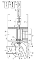
- FIG. 1 is an elevational configuration diagram illustrating a scanning irradiation apparatus to which a particle beam therapy system according to an embodiment is applied.
- the particle beam therapy system of the present embodiment generally includes a scanning irradiation device 1 as an irradiation unit, a CT device 2, an X-ray imaging device 3, and a treatment bed 4.
- the irradiation port 10, the CT apparatus 2, the X-ray imaging apparatus 3, and the treatment bed 4 of the scanning irradiation apparatus 1 are installed in the treatment room 14.
- the irradiation port 10 of the scanning irradiation apparatus 1 is disposed in the vicinity of the CT apparatus 2 and within a moving range when the CT apparatus 2 acquires an image (during imaging).
- the X-ray imaging apparatus 3 is composed of two sets, and X-ray tubes 5 a and 5 b are installed inside the floor surface 19.
- FPDs 6 a and 6 b are installed at the front ends of flat X-ray detector (Flat Panel Detector, hereinafter abbreviated as FPD) drive mechanisms 7 a and 7 b attached to the ceiling 9. Therefore, the X-ray imaging apparatus 3 is configured so that a fluoroscopic image can be acquired from two directions.
- FPD Flat X-ray detector
- the FPDs 6a and 6b can be moved up and down by driving the FPD driving mechanisms 7a and 7b, respectively.
- the FPDs 6a and 6b are in a lowered position when acquiring a fluoroscopic image. Further, when the CT apparatus 2 moves to the position of the treatment bed 4 at the CT imaging position, the FPDs 6a and 6b are raised to a position where they do not interfere with the CT apparatus 2.
- the irradiation port 10 for irradiating the patient mounted on the treatment bed 4 with the beam is installed at the distal end of the scanning irradiation apparatus 1.
- the irradiation port 10 is configured separately from the irradiation port movable unit 20 and the irradiation port fixing unit 30.
- the irradiation port movable unit 20 can move horizontally with respect to the irradiation port fixing unit 30 and is located within the movement range of the CT apparatus 2.
- the irradiation port movable unit 20 moves horizontally in a position that does not interfere with the CT apparatus 2, that is, in a direction perpendicular to the paper surface of FIG. 1.
- the scanning irradiation apparatus 1 includes an irradiation port 10 disposed in the treatment room 14, a scanning electromagnet 11 as a beam scanning electromagnet installed outside the treatment room 14, and a vacuum duct 12.
- One end of the vacuum duct 12 is fixed to the upstream side of the irradiation port 10, and the other end extends through the scanning electromagnet 11 to an accelerator take-out device 18 described later.
- the irradiation port movable unit 20 is arranged on the beam downstream side with respect to the decorative wall 13 standing in the treatment room 14.
- a range shifter 21 and a ridge filter 22 as a range adjuster are installed in the irradiation port movable unit 20.
- the irradiation port fixing part 30 is disposed on the beam upstream side with respect to the decorative wall 13.
- a part of the vacuum duct 12, a position monitor 31, and a dose monitor 32 are installed.
- the CT apparatus 2 is self-propelled, and is configured to move to the treatment bed 4 along two rails 33 laid on the floor surface 19 in the treatment room 14 in a direction perpendicular to the paper surface of FIG. ing.
- the CT apparatus 2 includes a plurality of traveling wheels 34 that travel on two rails 33, and any one of these traveling wheels 34 is connected to a drive motor (not shown). Therefore, when the drive motor is driven, the traveling wheel 34 travels along the two rails 33, so that the CT apparatus 2 can move to the treatment bed 4.
- the irradiation port movable unit 20 is at a position where it interferes. In this case, the irradiation port movable unit 20 is moved horizontally to prevent interference with the CT apparatus 2.
- the treatment bed 4 is configured to be movable up and down and left and right by a positioning device to be described later in order to finely adjust the position of the affected part of the patient on board.
- the ion source 15, the linear accelerator 16, and the synchrotron 17 constitute a beam generation unit of the present embodiment. Specifically, the beam generating unit generates ions by accelerating ions generated by the ion source 15 to energy that can reach deep into the affected area by the linear accelerator 16 and the synchrotron 17.
- the linear accelerator 16 accelerates ions generated by the ion source 15.
- a beam accelerated by the linear accelerator 16 is transported to the synchrotron 17, and this beam is circulated to further accelerate to a predetermined energy.
- the beam is taken out by the take-out device 18 and transported to the vacuum duct 12 penetrating the scanning electromagnet 11.
- the scanning electromagnet 11 scans the particle beam 8 incident on the scanning electromagnet 11 at a point (X, Y) on a plane (slice plane) perpendicular to the beam axis in the affected part in the body. This beam scanning is performed by controlling the output current of a scanning electromagnet power source (not shown).
- the range shifter 21 controls the position (Z) in the beam axis direction within the affected area in the body.
- the range shifter 21 is composed of an acrylic plate having a plurality of thicknesses, and by combining these acrylic plates, the beam energy passing through the range shifter 21, that is, the range within the body, is adjusted step by step according to the slice surface of the affected area. Can be changed. In-vivo range control in the range shifter 21 is generally switched at regular intervals.
- the ridge filter 22 is used to expand a very sharp peak dose in the body depth direction (referred to as a Bragg peak) of the monoenergetic particle beam so as to correspond to the interval of the body range switched by the range shifter 21. It is.
- the ridge filter 22 for scanning irradiation is configured by arranging a plurality of aluminum rod pieces. These bar pieces are formed in an approximately isosceles triangle shape, and the beam energy changes depending on the difference in the beam path length.
- the position monitor 31 is for identifying whether or not the beam position scanned by the scanning electromagnet 11 is in the correct position.
- the position monitor 31 has the same configuration as that of the dose monitor 32, and is divided into strips (strip type), or uses a collection electrode composed of a plurality of wires in a container (multi-wire type). used.
- the dose monitor 32 is for measuring the irradiation dose, and an ionization chamber or the like that collects charges generated by the ionizing action of the particle beam in the container with parallel electrodes is used.
- FIG. 2 is a flowchart showing an example of an irradiation procedure using the scanning irradiation apparatus of FIG.
- the incident energy of the particle beam and the plate thickness in the range shifter 21 are set so that the stop position of the particle beam corresponds to the deepest slice (Z1) of the affected area irradiation region (step S1). .
- the current value of the scanning electromagnet 11 is set so that the beam is irradiated to one point (X1, Y1) in the affected area irradiation area in this slice (step S2).
- the irradiation control device (not shown) outputs a command signal to the beam extraction control device, and the beam is emitted to start irradiation (step S3).
- the dose (preset value) to be irradiated to each position is obtained in advance.
- the irradiation control device receives a dose expiration signal, and the power supply of the scanning electromagnet 11 from the irradiation control device.
- a current switching command signal is output to the second point (X2, Y2, Z1), and the beam position is changed (step S4).
- the irradiation method in which the emission of the particle beam is temporarily stopped from when the irradiation control device outputs the current switching command signal until the switching completion command signal is received from the power source of the scanning electromagnet 11 is referred to as a spot scanning method.
- an irradiation method that does not stop the emission of the particle beam even while the current of the power source of the scanning electromagnet 11 is switched is referred to as a raster scanning method.
- the power source of the scanning electromagnet 11 is switched.
- the beam emission is stopped, and the slice position is changed to the previous slice position by changing the plate thickness of the range shifter 21 (step S5, S6).
- the current value of the scanning electromagnet 11 is set so that the beam is irradiated to one point (X1, Y1, Z2) in the affected area irradiation area in the next slice. Then, irradiation in the irradiation region is performed in the same manner as in the previous slice.
- the irradiation in the slice is sequentially performed, and a series of irradiation is completed by the end of irradiation of all the slices until the final slice (step S7).
- step S7 when the irradiation is not completed up to the final slice, the incident energy of the particle beam and the plate thickness in the range shifter 21 are set again (step S8). Thereafter, the processing from step S2 to step S7 is repeated, and a series of irradiation is completed by the end of irradiation of all slices until the last slice.
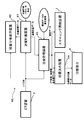
- FIG. 3 is a block diagram showing a control system of the particle beam therapy system according to one embodiment.
- the particle beam treatment system 40 includes a treatment planning device 41 as a calculation unit, a dose distribution display device 42, a treatment management device 43, a positioning device 44, a treatment bed 4, and the above-described scanning irradiation device as an irradiation unit. 1 and the CT apparatus 2 as a three-dimensional image acquisition unit.
- the CT apparatus 2 acquires a three-dimensional image of the affected area of the patient immediately before treatment (on the day of treatment) in the treatment room 14.
- the treatment management device 43 has functions as a selection unit, a deviation amount evaluation unit, and an irradiation position correction unit of the present embodiment.
- the treatment planning device 41, the dose distribution display device 42, and the treatment management device 43 constitute the particle beam treatment management system of this embodiment.
- the particle beam therapy system 40 of the present embodiment uses the CT apparatus 2 as a three-dimensional image acquisition unit, but besides this, an MRI (Magnetic Resonance Imaging) apparatus, PET (positron transmission etomography: (Positron emission tomography) —An image diagnostic apparatus capable of acquiring a three-dimensional image, such as a CT apparatus, may be used.
- an MRI Magnetic Resonance Imaging
- PET positron transmission etomography: (Positron emission tomography)
- An image diagnostic apparatus capable of acquiring a three-dimensional image, such as a CT apparatus, may be used.
- the treatment planning apparatus 41 is configured to avoid target isocenter (affected area center) information, beam angle information, affected area (Region of Interest: ROI) information, and normal to avoid irradiation.
- target isocenter (affected area center) information e.g., target isocenter (affected area center) information
- beam angle information e.g., beam angle information
- affected area e.g., ROI
- ROI affected area
- the organ position information and the like are set, the irradiation dose optimization calculation for the affected part is performed, and the setting information of the treatment bed 4 and irradiation data (pattern) to be described later are created.
- target isocenter (affected area center) information isocenter (affected area center) information, beam angle information, affected area (ROI) information, normal organ position information that should be avoided, irradiation position information, position setting data for the treatment bed 4,
- irradiation data pattern
- treatment plan data is collectively referred to as treatment plan data.
- the irradiation data is data that sets how to irradiate the irradiation area. Specifically, the irradiation data is data in which the irradiation dose at each irradiation spot is weighted so that the dose distribution to the affected area is uniform.
- the treatment planning apparatus 41 of the present embodiment can reuse at least one of the setting parameters at the time of the treatment planning that has been planned in advance for the in-vivo 3D image newly set by the CT apparatus 2.
- the setting parameters at the time of treatment planning include target isocenter (affected area center) information, beam angle information, affected area information, and normal organ position information that should be avoided from irradiation.
- the treatment planning device 41 can reuse the slice interval and the spot interval as device setting parameters necessary for creating irradiation data. Of these pieces of information, information that is not reused can be reset.
- the affected area (ROI) information and the normal organ position information to avoid irradiation are cross-sectional images of a three-dimensional image.
- the treatment planning apparatus 41 according to the present embodiment has a function of automatically setting a deviation amount or an irradiation region for another cross-sectional image when a positional deviation amount or an irradiation region is set for one cross-section with respect to the cross-sectional image. I have.
- the dose distribution display device 42 displays the newly acquired three-dimensional image, the original affected area information, the position information of the organ to avoid irradiation, and the irradiation dose distribution. That is, the dose distribution display device 42 applies the treatment plan data prepared in advance to the three-dimensional image acquired immediately before the treatment, calculates the dose distribution, and displays the irradiation dose distribution for the affected part or the normal organ. These functions are usually provided in the treatment planning apparatus 41 in many cases.
- the treatment planning device 41 and the dose distribution display device 42 may be used by being connected to the particle beam treatment system as being independent of the particle beam treatment system. In the present embodiment, however, the particle beam treatment includes them. System.
- the treatment management device 43 has a selection function for selecting whether to position the patient by the positioning device 44 or to change the treatment plan data prepared in advance in order to correct the position of the treatment bed 4 on which the patient is mounted. Have.
- the treatment management device 43 has a function of evaluating a deviation amount of the irradiation position based on the in-vivo three-dimensional image acquired immediately before the treatment (on the day of treatment), and an irradiation position for correcting the irradiation position data of the treatment plan data that is planned in advance. It has a correction function, a calculation function for performing dose optimization calculation of irradiation data in treatment plan data, and a selection function for selecting one of these functions.
- the treatment management apparatus 43 also has a function of setting irradiation position information in which the irradiation position is corrected in the scanning irradiation apparatus 1 in addition to the irradiation data of the treatment plan data prepared in advance.
- the treatment management device 43 also has a function of setting newly optimized irradiation data in the scanning irradiation device 1 without changing the position information of the treatment bed 4.
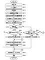
- FIG. 4 is a flowchart showing an example of a treatment sequence using the particle beam treatment system of one embodiment.
- FIG. 5 is a flowchart showing processing by the treatment planning apparatus according to the embodiment.
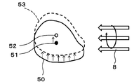
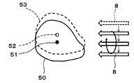
- FIG. 6 is an explanatory diagram showing an irradiation region when the treatment bed position is corrected by the particle beam therapy system of one embodiment.
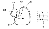
- FIG. 7 is an explanatory diagram showing an irradiation region when treatment plan data is changed in the particle beam therapy system of one embodiment.
- FIG. 8 is an explanatory diagram showing affected area information and organ position information to be avoided when target isocenter and beam angle information are used in the treatment planning apparatus of one embodiment.
- CT imaging is performed in advance (before the treatment date) in the treatment room 14 in which the CT apparatus 2 is installed to obtain a three-dimensional image.
- the position estimated as the center of the affected part is marked on the surface of the fixture for fixing the patient to the treatment bed 4.
- a treatment plan is made using the CT images acquired in the treatment room 14.
- an irradiation area is set, and irradiation data (irradiation pattern) in which how irradiation is performed for this irradiation area and position setting data of the treatment bed 4 are created.
- treatment plan data prepared in advance immediately before or when a patient enters the treatment room 14, that is, position setting data and irradiation data of the treatment bed 4 related to treatment are read from the treatment plan apparatus 41 to the treatment management apparatus 43. (Steps S11 and S12).
- the patient who entered the treatment room 14 is mounted on the treatment bed 4 and the patient is fixed with a fixture (step S13).
- the treatment bed 4 is moved using the positioning device 44 so that the mark marked on the fixture in the treatment room 14 matches the target isocenter (center of the affected part).
- the treatment management device 43 sets position setting data in the treatment bed 4 and operates the input device of the treatment bed 4 to move to the set position (step S14).
- the treatment planning device 41 retracts the irradiation port movable unit 20 from the irradiation position, sets the measurement unit (gantry) 2a of the CT apparatus 2 to the affected area, and performs CT imaging (step S15). That is, in step S15, the treatment planning device 41 acquires a three-dimensional image of the body on the treatment day using the CT device 2. The treatment planning device 41 calculates a dose distribution based on the acquired three-dimensional image (step S16), and transmits the dose distribution data to the dose distribution display device.
- the dose distribution for the treatment plan prepared in advance and the dose distribution based on the three-dimensional image of the body on the treatment day are displayed side by side or overlaid (step S17).
- step S18 it is selected whether or not to change the treatment plan data prepared in advance (step S18) and whether or not to correct the position of the treatment bed 4 on which the patient is mounted (step S19). That is, step S19 selects whether or not to perform positioning for correcting the patient's position.
- the selection processing in steps S18 and S19 is performed by operating the input / output device of the treatment management device 43. In the present embodiment, it is assumed that the medical staff performs the selection process in steps S18 and S19. However, the present invention is not limited to this, and the difference between the results displayed in step S17 is evaluated and automatically determined. You may do it.
- step S18; No When the change of the treatment plan data is not selected (step S18; No), and the correction of the position of the treatment bed 4 is selected (step S19; Yes), the treatment management device 43 preliminarily acquires the CT image acquired this time and The CT image (reference image) acquired in the treatment room 14 is compared, and the shift amount of the affected part position is evaluated (step S20).
- the treatment management apparatus 43 sets a position correction value for the treatment bed 4 based on the displacement amount of the affected part position (step S21).
- the treatment management device 43 transmits the position correction value to the treatment bed 4 and moves the treatment bed 4 by the position correction value to align the patient (step S22) (3D-3D positioning). .
- a target isocenter (affected area center) 51 in the treatment plan is set in the irradiation region 50 in which a treatment plan has been prepared in advance.
- the treatment bed 4 is moved based on the amount of displacement of the affected part position so that the affected part center and the treatment apparatus isocenter 52 coincide.
- the irradiation data uses the calculation result before the treatment date. That is, the irradiation pattern of the particle beam 8 is not affected.
- the measurement unit (gantry) 2a of the CT apparatus 2 is retracted, and the irradiation port movable unit 20 is returned to a predetermined position. Then, the affected area irradiation data is set in the scanning irradiation apparatus 1, and an irradiation start button on an irradiation console (not shown) is pressed to start irradiation on the affected area (steps S23 and S24).
- step S19 if the position of the treatment bed 4 on which the patient is mounted is not corrected (step S19; No), the process proceeds directly to step S23 without setting the steps S20 to S22, and the affected area irradiation data is set. To do.
- step S18 the treatment management device 43 determines whether or not to perform the optimization calculation of the irradiation data of the treatment plan data (step S25).
- step S25 the treatment plan data is changed (step S26). In this step S26, only the spot position (X, Y) and slice setting (Z) are corrected in the irradiation data, and the weighting of the irradiation dose of each irradiation spot is not changed.
- the treatment bed 4 is not moved, and the amount of the difference is the particle beam.
- the irradiation position of the beam 8 is moved to match the irradiation area with the affected area.
- the CT image acquired this time is compared with the CT image (reference image) acquired in advance in the treatment room 14, and the displacement of the affected part position is compared. Evaluate the amount. Then, the irradiation position information of the treatment plan data is corrected by moving in parallel by the amount of displacement of the affected part position.
- the treatment plan data is changed by translating the irradiation position.
- the present invention is not limited to this, and the range may be changed by changing the irradiation energy, for example.
- the beam angle information may be further changed and corrected.
- the measurement unit 2a of the CT apparatus 2 is retracted in the same manner as described above, and the irradiation port movable unit 20 is returned to a predetermined position. Then, the affected area irradiation data is set with the treatment plan data in which the irradiation position is changed with respect to the scanning irradiation apparatus 1, and the irradiation start button of an irradiation console (not shown) is pressed to start irradiation on the affected area (steps S23 and S24).
- the treatment planning apparatus 41 When the treatment management apparatus 43 selects execution of the irradiation data optimization calculation (step S25; Yes), the treatment planning apparatus 41 performs irradiation data optimization calculation. Specifically, as illustrated in FIG. 5, the treatment planning apparatus 41 reads the CT image acquired on the treatment day in the process of step S15 (step S27).
- the treatment management apparatus 43 determines whether to use the affected part center information and beam angle information in the original treatment plan data (step S28). When the affected part center information and beam angle information of the original treatment plan are used (step S28; Yes), the affected part center information and beam angle information are used (step S29).
- the target isocenter (affected area center) 51, the beam angle, and the pre-planned irradiation area 50 of the affected area when a treatment plan is made using the CT image acquired in the treatment room 14 are shown.
- the affected area information (ROI) and the position information of the normal organ 54 that should avoid irradiation are read. Further, the slice interval and the spot interval are read as device setting parameters necessary for creating irradiation data. Then, the target isocenter 51 and the beam angle are set as the setting conditions for the optimization calculation.
- the affected area information indicating the irradiated area 50 of the affected area and the position information of the normal organ 54 are overlaid and displayed on the irradiated area 53 and the normal organ 55 of the CT image acquired on the treatment day.
- these areas are corrected.
- correction of the affected area and the normal organ area is performed on one section of the CT image.
- the entire cross section is corrected by automatically reflecting the change amount and deformation amount of the center of gravity of these areas for the other cross sections.
- the treatment planning apparatus 41 redoes the irradiation data optimization calculation (step S30).
- the affected area (ROI) information indicating the irradiated area 50 of the affected area is set for all slices of the affected area, the center information and the beam angle information are set for the representative slice of the affected area, and normal irradiation should be avoided.
- the position information of the organ 54 other parameters are set. Then, the position and weight of each spot in the irradiation data are reset.
- the treatment planning device 41 performs the irradiation data optimization calculation again, confirms the dose distribution result, and if there is no problem, rewrites the treatment plan data and transmits it to the treatment management device 43. At this time, since the target isocenter 51 and the beam angle are not changed as described above, the position information of the treatment bed 4 is not changed.
- the treatment management device 43 retracts the measurement unit 2a of the CT device 2 and returns the irradiation port movable unit 20 to a predetermined position. At this time, since the set value of the treatment bed 4 has not changed, the movement of the treatment bed 4 is not necessary. Then, after outputting the irradiation data optimized for the scanning irradiation apparatus 1 (step S31), the irradiation data of the affected area is rewritten based on the irradiation data calculated for optimization, and the irradiation start button of the irradiation console (not shown) is pressed to enter the affected area. On the other hand, irradiation is started (steps S23 and S24).
- the treatment planning apparatus 41 When there is a problem in the dose distribution after redoing the optimization calculation using the values at the time of the previous treatment plan as the target isocenter 51 and the beam angle, or when it is clear that these values must be reset ( In step S28; No), the treatment planning apparatus 41 resets the target isocenter 51 and the beam angle (step S32), and resets the treatment plan. Then, the treatment planning device 41 transmits the re-planned treatment plan data to the treatment management device 43.
- the treatment management device 43 retracts the measurement unit 2a of the CT device 2 and returns the irradiation port movable unit 20 to a predetermined position. At this time, since the set value of the treatment bed 4 has changed, the treatment bed 4 is moved. Then, similarly to step S30, the irradiation data optimization calculation is performed again (step S33).
- the treatment management apparatus 43 outputs the position setting data to the treatment bed 4 and outputs the irradiation data calculated by optimization (Step S34), and then proceeds to Step S21.
- the dose distribution is calculated by applying pre-prepared treatment plan data to the three-dimensional image acquired immediately before the treatment, and the irradiation dose to the affected part or normal organ is displayed. Like to do.
- the present embodiment configured as described above, even if the fixed position of the affected part or the state of the internal organs is different from the treatment plan that is planned in advance, it is possible to change the treatment plan data that is planned in advance immediately before the treatment. Thus, it becomes possible to accurately irradiate the affected part with the particle beam during the treatment.
- the irradiation area of the affected part can be set based on the in-vivo three-dimensional image acquired immediately before the treatment, the affected part is acquired from the time of acquiring the three-dimensional image used for the treatment plan prepared in advance. Even if the position and the position of the normal tissue change, it is possible to avoid the normal tissue and irradiate the affected part with the beam with high accuracy.
- the present embodiment since it has a function as an irradiation position correction unit that corrects the irradiation position of treatment plan data prepared in advance, there is no need to perform optimization calculation of the treatment plan.
- the time from the acquisition of the three-dimensional image to the start of irradiation can be shortened.
- the target isocenter 51 and beam angle information of the treatment plan prepared in advance can be used, the result of performing the dose optimization calculation is set in the scanning irradiation apparatus 1. Therefore, it is not necessary to reset the position of the treatment bed 4. Therefore, time for resetting the treatment bed 4 is not required.
- the treatment bed 4 is moved, it is not necessary to perform X-ray imaging for confirming that the position is correct, and the setting time of the device for X-ray imaging becomes unnecessary. As a result, the time required for treatment can be shortened.
- the treatment planning apparatus 41 of the present embodiment it is possible to use the affected area information of the treatment plan prepared in advance or the position information of the organ to avoid irradiation, so that the time required for the treatment plan is shortened. be able to.
- the affected area information and the position of the normal organ to be avoided if the positional deviation amount is set for one cross-section with respect to the cross-sectional image of the three-dimensional image, the deviation amount is automatically set for the other cross-sectional images. , The workload of the doctor or radiologist can be reduced.
- the irradiation dose is usually divided into a plurality of doses and irradiated over several days.
- the description of the above embodiment is based on the setting parameter of the treatment plan for the CT image acquired in the treatment room 14, but from the second time, the setting parameter when recalculated in the treatment room 14 is used as the reference point. Good.
- SYMBOLS 1 Scanning irradiation apparatus (irradiation part), 2 ... CT apparatus (three-dimensional image acquisition part), 2a ... Measurement part, 3 ... X-ray imaging apparatus, 4 ... Treatment bed, 5a, 5b ... X-ray tube, 6a, 6b ... FPD, 7a, 7b ... FPD drive mechanism, 8 ... particle beam, 9 ... ceiling, 10 ... irradiation port, 11 ... scanning electromagnet, 12 ... vacuum duct, 13 ... decorative wall, 14 ... treatment room, 15 ... ion source , 16 ... Linear accelerator, 17 ... Synchrotron, 18 ... Extraction device, 19 ... Floor surface, 20 ...
- Irradiation port movable part 21 ... Range shifter, 22 ... Ridge filter, 30 ... Irradiation port fixing part, 31 ... Position monitor, 32 ... Dose monitor, 33 ... Rail, 34 ... Traveling wheel, 40 ... Particle beam therapy system, 41 ... Treatment planning device, 42 ... Dose distribution display device (dose distribution display unit), 43 ... Treatment management device (selection unit, deviation) Evaluation unit, arithmetic unit, the irradiation position correcting unit), 44 ... positioning device 50 ... irradiation region, 51 ... target isocenter, 52 ... treatment apparatus isocenter, 53 ... irradiation region, 54 ... normal organs, 55 ... normal organs
Landscapes
- Health & Medical Sciences (AREA)
- Engineering & Computer Science (AREA)
- Biomedical Technology (AREA)
- General Health & Medical Sciences (AREA)
- Life Sciences & Earth Sciences (AREA)
- Veterinary Medicine (AREA)
- Public Health (AREA)
- Pathology (AREA)
- Nuclear Medicine, Radiotherapy & Molecular Imaging (AREA)
- Radiology & Medical Imaging (AREA)
- Animal Behavior & Ethology (AREA)
- Theoretical Computer Science (AREA)
- Physics & Mathematics (AREA)
- General Physics & Mathematics (AREA)
- Computer Graphics (AREA)
- Computer Vision & Pattern Recognition (AREA)
- Multimedia (AREA)
- Signal Processing (AREA)
- Radiation-Therapy Devices (AREA)
Abstract
実施形態の粒子線治療システムは、治療室に設置されて治療当日の体内3次元画像を取得する3次元画像取得部であるCT装置(2)と、治療当日に取得した3次元画像による線量分布と、あらかじめ立案された治療計画データの線量分布とを表示する線量分布表示部である線量分布表示装置(42)と、治療当日の3次元画像による線量分布及びあらかじめ立案された治療計画データの線量分布に基づいて、治療計画データを変更するか否かを選択する選択部である治療管理装置(43)と、治療管理装置(43)での選択に基づく治療計画データによって患部に粒子線ビームを照射する照射部であるスキャニング照射装置(1)と、を備える。
Description
本発明の実施形態は、炭素等の重粒子線ビーム又は陽子ビーム等の粒子線ビーム(以下、単にビームともいう。)を例えば患部に照射し、がん治療を行う粒子線治療システム、粒子線治療用管理システム及び方法に関する。
現在、がん治療には、例えば粒子線照射方法が使用されている。この粒子線照射方法には、拡大ビーム法と呼ばれる方法がある。この拡大ビーム法では、ワブラ法、あるいは二重散乱体法と呼ばれる方法によりビーム径を患部サイズ以上に拡大している。また、拡大ビーム法は、コリメータにより照射領域を制限することにより、患部形状に合致させて照射を行う。しかし、拡大ビーム法は、厳密には3次元的に患部形状に合致させることができず、患部周りの正常細胞への影響を小さくするには限界がある。
そこで、3次元スキャニング照射法が開発された。3次元照射法では、患部を3次元的に塗りつぶすように照射を行い、コリメータを必要としないのが特徴の一つである。この3次元スキャニング照射法による粒子線治療は、次の第1ステップ~第3ステップの手順で行われる。
まず、第1ステップでは、あらかじめ治療計画を立案するためにコンピュータ断層撮影(Computed Tomography、以下、CTと略称する。)が行われる。この撮影によるCT画像は、治療計画の立案の他、治療時の患者位置決め用の参照画像を作成するためにも用いられる。この第1ステップは通常、治療の日前に行われる。
第2ステップは、患者の位置設定である。具体的には、患者を治療寝台に搭載し、患者を固定する固定具の表面に記されたマークを照射中心に合わせる。この状態で、X線透視撮影を行う。このX線透視撮影で得られた透視画像と、あらかじめCT画像により作成した上記参照画像とを比較し、位置のずれ量を求める。そして、この位置のずれ量を治療寝台に設定し、透視画像と参照画像とが合うようにする。
第3ステップは、粒子線照射である。具体的には、患者の位置設定終了後に照射システムの各機器を照射可能な状態に設定した後に照射を開始する。3次元スキャニング照射法は、あらかじめCT画像を元に立案した治療計画に従って患部の照射を行っていく方法である。
JOURNAL OF APPLIED CLINICAL MEDICAL PHYSICS, Vol.13, Num.6,2012, Patient handling system for carbon ion beam scanning therapy, S. Mori, et.al.
しかしながら、上記の手順で治療を行う場合、第1ステップの作業は、治療の前日以前に行われるため、患者の体内ガス及び消化物、体内排泄物の状態により、患部の位置及び正常組織の位置が変化してしまう場合がある。この場合、治療寝台に患者の位置を再設定したとしても、それにともなう位置再現性が問題になる。
また、第2ステップでは、X線撮影後に治療寝台を移動させる操作が必要であるため、治療寝台の位置精度に対する要求が高くなり、日常(通常は、毎朝の治療開始前)のQA(Quality Assurance:品質保証)試験に時間がかけられている。さらに、治療寝台を移動させた後に、その位置が正しいことを確認するため、再度X線撮影を行う必要がある。その結果、X線撮影のための機器設定時間が長くかかるとともに、患者の被ばく線量が高くなってしまうという問題がある。
本実施形態が解決しようとする課題は、患部の固定位置又は体内臓器の状態があらかじめ立案した治療計画と異なっていても、患部に粒子線ビームを正確に照射することのできる粒子線治療システム、粒子線治療用管理システム及び方法を提供する。
上記課題を解決するために、本実施形態に係る粒子線治療システムは、治療室に設置されて治療当日の体内3次元画像を取得する3次元画像取得部と、前記治療当日に取得した3次元画像による線量分布と、あらかじめ立案された治療計画データの線量分布とを表示する線量分布表示部と、前記治療当日の3次元画像による線量分布及び前記あらかじめ立案された治療計画データの線量分布に基づいて、前記治療計画データを変更するか否かを選択する選択部と、前記選択部での選択に基づく治療計画データによって患部に粒子線ビームを照射する照射部と、を備えることを特徴とする。
本実施形態の粒子線治療用管理システムは、治療室に設置されて治療当日の体内3次元画像を取得する3次元画像取得部と、前記治療当日に取得した3次元画像による線量分布と、あらかじめ立案された治療計画データの線量分布とを表示する線量分布表示部と、前記治療当日の3次元画像による線量分布及び前記あらかじめ立案された治療計画データの線量分布に基づいて、前記治療計画データを変更するか否かを選択する選択部とを備え、前記選択部での選択に基づく変更された前記治療計画データによって前記治療計画データを更新するようにしたことを特徴とする。
本実施形態の粒子線治療用管理方法は、治療室に設置されて治療当日の体内3次元画像を取得する3次元画像取得工程と、前記治療当日に取得した3次元画像による線量分布と、あらかじめ立案された治療計画データの線量分布とを表示する線量分布表示工程と、前記治療当日の3次元画像による線量分布及び前記あらかじめ立案された治療計画データの線量分布に基づいて、前記治療計画データを変更するか否かを選択する選択工程と、前記選択工程での選択に基づく変更された前記治療計画データによって前記治療計画データを更新する更新工程と、を有することを特徴とする。
本実施形態によれば、患部の固定位置又は体内臓器の状態があらかじめ立案した治療計画と異なっていても、患部に粒子線ビームを正確に照射することが可能になる。
以下、本実施形態に係る粒子線治療システム及び粒子線治療用管理システムについて、図面を参照して説明する。
(一実施形態)
図1は一実施形態の粒子線治療システムが適用されるスキャニング照射装置を示す立面構成図である。
図1は一実施形態の粒子線治療システムが適用されるスキャニング照射装置を示す立面構成図である。
図1に示すように、本実施形態の粒子線治療システムは、概ね照射部としてのスキャニング照射装置1と、CT装置2と、X線撮影装置3と、治療寝台4と、を備える。これらスキャニング照射装置1の照射ポート10、CT装置2、X線撮影装置3、及び治療寝台4は、治療室14内に設置されている。スキャニング照射装置1の照射ポート10は、CT装置2の近傍であって、CT装置2の画像取得時(撮影時)における移動範囲内に設置されている。
X線撮影装置3は、2セットで構成され、床面19の内部にX線管5a,5bが設置されている。X線撮影装置3は、天井9に取り付けた平面X線検出器(Flat Panel Detector、以下、FPDと略称する。)駆動機構7a,7bの先端部にFPD6a,6bが設置されている。したがって、このX線撮影装置3では、2方向から体内透視画像を取得できるように構成されている。
FPD6a,6bは、それぞれFPD駆動機構7a,7bを駆動することにより昇降可能である。FPD6a,6bは、体内透視画像を取得する場合、下降した位置にある。また、FPD6a,6bは、CT装置2がCT撮影位置の治療寝台4の位置まで移動する場合、CT装置2と干渉しない位置まで上昇している。
スキャニング照射装置1の先端部には、治療寝台4に搭載された患者にビームを照射する照射ポート10が設置されている。この照射ポート10は、照射ポート可動部20と、照射ポート固定部30とから分離して構成されている。照射ポート可動部20は、照射ポート固定部30に対して水平移動可能であって、CT装置2の移動範囲内に位置している。照射ポート可動部20は、CT装置2が治療寝台4の位置まで移動する場合、CT装置2と干渉しない位置、つまり図1の紙面に垂直な方向へ水平移動する。
スキャニング照射装置1は、治療室14内に配置された照射ポート10と、治療室14外に設置されたビーム走査電磁石としてのスキャニング電磁石11と、真空ダクト12とを備える。この真空ダクト12の一端は、照射ポート10の上流側に固定され、他端はスキャニング電磁石11を貫通して後述する加速器の取出し機器18まで延びている。
照射ポート可動部20は、治療室14内に立設された化粧壁13に対してビーム下流側に配置されている。照射ポート可動部20内には、飛程調整器としてのレンジシフタ21、リッジフィルタ22が設置されている。
照射ポート固定部30は、化粧壁13に対してビーム上流側に配置されている。照射ポート固定部30内には、真空ダクト12の一部、位置モニタ31、線量モニタ32が設置されている。
CT装置2は、自走式であり、治療室14内の床面19に、図1の紙面に垂直な方向に敷設された2本のレール33に沿って治療寝台4まで移動可能に構成されている。具体的には、CT装置2は、2本のレール33を走行する複数の走行車輪34を備え、これらの走行車輪34のうちいずれか一方が図示しない駆動モータと連結されている。したがって、上記駆動モータを駆動させると、走行車輪34が2本のレール33に沿って走行することで、CT装置2は、治療寝台4まで移動することができる。
CT装置2によるCT撮影時には、照射ポート可動部20が干渉する位置にある。この場合には、照射ポート可動部20が水平移動することで、CT装置2と干渉しないようにしている。
治療寝台4は、搭載した患者の患部の位置を微調整するために後述する位置決め装置によって上下左右に移動可能に構成されている。
次に、図1で示したスキャニング照射装置1の各機器の機能について説明する。
イオン源15、線形加速器16及びシンクロトロン17は、本実施形態のビーム生成部を構成する。具体的に、このビーム生成部は、イオン源15で発生させたイオンを線形加速器16、シンクロトロン17によって患部の奥深くまで到達可能なエネルギーまで加速してビームを生成している。
すなわち、線形加速器16は、イオン源15で発生させたイオンを加速する。シンクロトロン17には、線形加速器16で加速したビームが輸送され、このビームを周回させて所定のエネルギーまでさらに加速する。ビームの加速終了後は、取出し機器18によりビームが取り出され、スキャニング電磁石11を貫通した真空ダクト12に輸送される。
スキャニング電磁石11は、スキャニング電磁石11に入射した粒子線ビーム8を体内患部内のビーム軸に対する垂直面(スライス面)の上の点(X、Y)を走査する。このビームの走査は、図示しないスキャニング電磁石用電源の出力電流を制御することで行う。
レンジシフタ21は、体内患部内のビーム軸方向の位置(Z)を制御する。レンジシフタ21は、複数の厚さのアクリル板から構成されており、これらのアクリル板を組み合わせることにより、レンジシフタ21を通過するビームエネルギー、すなわち体内飛程を、患部のスライス面に合わせて段階的に変化させることができる。レンジシフタ21における体内飛程の制御は、一般的には一定間隔をもって切り替えられる。なお、飛程の切り替えには、レンジシフタ21のようにビームラインに物体を挿入する方法の他、ビーム上流側に設置された機器を電気的に制御することによってビームエネルギー自体を変更する方法もある。
リッジフィルタ22は、単エネルギー粒子線ビームの非常にシャープな体内深さ方向のピーク線量(ブラッグピークと呼ばれる)を、レンジシフタ21によって切り替えられる体内飛程の間隔に対応するように拡大するためのものである。
スキャニング照射用のリッジフィルタ22は、アルミニウム製の棒片が複数並べられて構成されている。これら棒片は、ほぼ二等辺三角形の形状に形成され、ビームの経路長の違いによってビームエネルギーが変化するようになっている。
位置モニタ31は、スキャニング電磁石11により走査されたビーム位置が正しい位置にあるかどうかを識別するためのものである。位置モニタ31は、線量モニタ32と同様の構成を有し、短冊状に分割されたもの(ストリップ型)、あるいは容器内に複数のワイヤからなる収集電極を用いたもの(マルチワイヤ型)等が使用される。
線量モニタ32は、照射線量を測定するためのものであり、容器内にて粒子線の電離作用により生じた電荷を平行電極で収集する電離箱等が用いられる。
このようなスキャニング照射装置1を用いて、以下の方法によりスキャニング照射が行われる。図2は図1のスキャニング照射装置を用いた照射手順の一例を示すフローチャートである。
図2に示すように、まず、粒子線ビームの停止位置が患部照射領域の最深スライス(Z1)に対応するよう、粒子線ビームの入射エネルギーとレンジシフタ21における板厚が設定される(ステップS1)。
次に、このスライスにおける患部照射領域内の一点(X1、Y1)にビームが照射されるように、スキャニング電磁石11の電流値が設定される(ステップS2)。ビーム位置(X1、Y1、Z1)の設定が完了すると、図示しない照射制御装置はビーム出射制御装置に指令信号を出力し、ビームが出射されて照射を開始する(ステップS3)。
上記照射制御装置には、各位置に照射する線量(プリセット値)があらかじめ求められている。線量モニタ32から出力される最初の点(X1、Y1、Z1)の線量測定値がプリセット値に到達すると、上記照射制御装置が線量満了信号を受信し、上記照射制御装置からスキャニング電磁石11の電源に電流切替指令信号を出力し、次の点(X2、Y2、Z1)へビーム位置の変更が行われる(ステップS4)。
ここで、上記照射制御装置が電流切替指令信号を出力してからスキャニング電磁石11の電源より切替完了指令信号を受けるまでに、粒子線ビームの出射を一旦停止する照射法をスポットスキャニング法と言う。また、スキャニング電磁石11の電源の電流切替中も粒子線ビームの出射を停止しない照射法をラスタースキャニング法と言う。
以下、線量測定値がプリセット値に到達する毎にスキャニング電磁石11の電源の電流切替を行っていく。そして、スライス中の最終照射点(XN、YN、Z1)に到達すると、ビーム出射が停止され、レンジシフタ21の板厚を変更することにより、一つ手前のスライス位置に変更される(ステップS5、S6)。
今度は、次のスライスにおける患部照射領域内の一点(X1、Y1、Z2)にビームが照射されるように、スキャニング電磁石11の電流値が設定される。そして、先のスライスと同様に照射領域内の照射を行っていく。
このように順次、スライス内の照射を行っていき、最終スライスまで、全スライスの照射の終了により一連の照射を終了する(ステップS7)。
なお、このステップS7において、最終スライスまで照射が終了していない場合には、粒子線ビームの入射エネルギーとレンジシフタ21における板厚が再び設定される(ステップS8)。その後、ステップS2からステップS7の処理を繰り返し、最終スライスまで、全スライスの照射の終了により一連の照射を終了する。
次に、本実施形態の粒子線治療システムの全体構成について説明する。
図3は一実施形態の粒子線治療システムの制御系を示すブロック図である。
図3に示すように、粒子線治療システム40は、演算部としての治療計画装置41、線量分布表示装置42、治療管理装置43、位置決め装置44、治療寝台4、照射部としての上記スキャニング照射装置1、及び3次元画像取得部としての上記CT装置2を備える。このCT装置2は、治療室14内において治療直前(治療当日)の患者の患部の3次元画像を取得する。
治療管理装置43は、本実施形態の選択部、ずれ量評価部、及び照射位置補正部としての機能を有する。治療計画装置41、線量分布表示装置42、及び治療管理装置43は、本実施形態の粒子線治療用管理システムを構成する。
なお、本実施形態の粒子線治療システム40は、3次元画像取得部としてCT装置2を用いているが、これ以外に、MRI(Magnetic Resonance Imaging:磁気共鳴画像)装置、PET(positron emission tomography:陽電子放出断層撮影)-CT装置等のように3次元画像を取得可能な画像診断装置を用いてもよい。
治療計画装置41は、CT装置2から取得した体内3次元画像に基づいて、ターゲットアイソセンター(患部中心)情報、ビーム角度情報、患部領域(Region of Interest:ROI)情報、及び照射を避けるべき正常臓器の位置情報等を設定し、患部に対する照射線量の最適化計算を行い、治療寝台4の設定情報及び後述する照射データ(パターン)を作成する。
なお、以下の説明では、ターゲットアイソセンター(患部中心)情報、ビーム角度情報、患部領域(ROI)情報、及び照射を避けるべき正常臓器の位置情報、照射位置情報、治療寝台4の位置設定データ、及び後述する照射データ(パターン)等を一括して治療計画データともいう。
上記照射データとは、照射領域に対してどのように照射を行うかを設定したデータである。具体的には、上記照射データとは、患部への線量分布が均一になるように、各照射スポットの照射線量に重み付けを設定したデータである。
本実施形態の治療計画装置41は、CT装置2により新しく設定された体内3次元画像に対して、あらかじめ立案した治療計画時の設定パラメータの少なくとも一つを再利用することが可能である。この治療計画時の設定パラメータには、例えばターゲットアイソセンター(患部中心)情報、ビーム角度情報、患部領域情報、及び照射を避けるべき正常臓器の位置情報が挙げられる。また、治療計画装置41は、照射データを作成する上で必要な機器設定パラメータとして、スライス間隔、スポット間隔を再利用することが可能である。なお、これらの情報のうち、再利用しない情報は、再設定可能である。
患部領域(ROI)情報及び照射を避けるべき正常臓器の位置情報は、3次元画像の断面像である。本実施形態の治療計画装置41は、この断面像に対して一つの断面について位置ずれ量あるいは照射領域を設定すると、他の断面像についてもずれ量あるいは照射領域が自動的に設定される機能を備えている。
線量分布表示装置42は、新たに取得した3次元画像と、元の患部領域情報、照射を避けるべき臓器の位置情報、及び照射線量分布を表示する。すなわち、線量分布表示装置42は、治療直前に取得した3次元画像に対して、あらかじめ立案された治療計画データを適用して線量分布を計算し、患部又は正常臓器に対する照射線量分布を表示する。これらの機能は、通常治療計画装置41に設けられている場合が多い。
治療計画装置41及び線量分布表示装置42は、粒子線治療システムとは独立したものとして粒子線治療システムと接続して使用される場合があるが、本実施形態では、それらを含めて粒子線治療システムとする。
治療管理装置43は、患者を搭載した治療寝台4の位置を修正するため、位置決め装置44により患者の位置決めを行うか、あらかじめ立案された治療計画データを変更するか否かを選択する選択機能を有する。
治療管理装置43は、治療直前(治療当日)に取得した体内3次元画像に基づいて照射位置のずれ量を評価する機能と、あらかじめ立案された治療計画データの照射位置データの補正を行う照射位置補正機能と、治療計画データにおける照射データの線量最適化計算を行う演算機能と、これらの機能のいずれかを選択する選択機能と、を有する。
治療管理装置43は、あらかじめ立案された治療計画データの照射データ以外に、照射位置の補正が行われた照射位置情報をスキャニング照射装置1に設定する機能も有している。また、治療管理装置43は、治療寝台4の位置情報を変更せずに、新しく最適化された照射データをスキャニング照射装置1に設定する機能も有している。
次に、本実施形態の粒子線治療システムを用いた治療順序について説明する。
図4は一実施形態の粒子線治療システムを用いた治療順序の一例を示すフローチャートである。図5は一実施形態の治療計画装置による処理を示すフローチャートである。図6は一実施形態の粒子線治療システムで治療寝台位置の補正を行った場合の照射領域を示す説明図である。図7は一実施形態の粒子線治療システムで治療計画データの変更を行った場合の照射領域を示す説明図である。図8は一実施形態の治療計画装置でターゲットアイソセンター及びビーム角度情報を利用したときの患部領域情報と避けるべき臓器の位置情報を示す説明図である。
まず、CT装置2が設置された治療室14内においてあらかじめ(治療日前)CT撮影を行い、3次元画像を取得する。このとき、治療寝台4に患者を固定するための固定具の表面に患部の中心と推定される位置をマーキングしておく。
そして、治療室14内で取得したCT画像を用いて治療計画を立案する。この治療計画では、照射領域を設定するとともに、この照射領域についてどのように照射を行うかが記録された照射データ(照射パターン)及び治療寝台4の位置設定データを作成する。
次に、本実施形態の粒子線治療システムによる治療直前(治療当日)の治療順序を図4及び図5に従って説明する。
まず、治療室14への患者の入室直前、あるいは入室時にあらかじめ立案された治療計画データ、すなわち、治療に関する治療寝台4の位置設定データ及び照射データが治療計画装置41から治療管理装置43に読み出される(ステップS11、S12)。
治療室14内に入室した患者を治療寝台4に搭載し、固定具で患者を固定する(ステップS13)。治療室14内において固定具にマーキングした印をターゲットアイソセンター(患部中心)に合致するように位置決め装置44を用いて治療寝台4を移動させる。さらに、治療管理装置43は、治療寝台4に位置設定データを設定し、治療寝台4の入力装置を操作してその設定位置に移動させる(ステップS14)。
次いで、治療計画装置41は、照射ポート可動部20を照射位置から退避させ、CT装置2の測定部(ガントリ)2aを患部領域に設定し、CT撮影を行う(ステップS15)。すなわち、ステップS15では、治療計画装置41は、CT装置2を用いて治療当日の体内の3次元画像を取得する。治療計画装置41は、この取得した3次元画像による線量分布を計算し(ステップS16)、その線量分布データを線量分布表示装置42に送信する。
線量分布表示装置42では、あらかじめ立案した治療計画に対する線量分布と、上記治療当日の体内の3次元画像による線量分布を並べて表示、あるいは重ね書き表示をする(ステップS17)。
次に、あらかじめ立案された治療計画データを変更するか否か(ステップS18)、患者を搭載した治療寝台4の位置を修正するか否か(ステップS19)を選択する。すなわち、ステップS19は、患者の位置を修正する位置決めを行うか否かを選択する。ステップS18、S19の選択処理は、治療管理装置43の入出力装置を操作することにより行う。なお、本実施形態では、ステップS18、S19の選択処理を医療従事者が行うことを想定しているが、これに限らずステップS17において表示される結果の差分を評価し、自動的に判別するようにしてもよい。
治療計画データの変更を選択しない場合(ステップS18;No)であって、治療寝台4の位置の修正を選択した場合(ステップS19;Yes)、治療管理装置43は、今回取得したCT画像とあらかじめ治療室14で取得したCT画像(参照画像)とを比較し、患部位置のずれ量を評価する(ステップS20)。
そして、治療管理装置43は、この患部位置のずれ量に基づいて治療寝台4の位置補正値を設定する(ステップS21)。また、治療管理装置43は、この位置補正値を治療寝台4に送信し、その位置補正値分、治療寝台4を移動させることにより患者の位置合せを行う(ステップS22)(3D-3D位置決め)。
すなわち、図6に示すように、あらかじめ治療計画が立案された照射領域50には、治療計画上のターゲットアイソセンター(患部中心)51が設定されている。本実施形態では、患部位置のずれ量に基づいて、患部中心と治療装置アイソセンター52とが一致するように、治療寝台4を移動する。このとき照射データは治療日前の計算結果を用いる。つまり、粒子線ビーム8の照射パターンには影響を与えない。
次いで、患者の位置合わせが完了した後は、CT装置2の測定部(ガントリ)2aを退避させ、照射ポート可動部20を所定位置に戻す。そして、スキャニング照射装置1に患部照射データを設定し、図示しない照射コンソールの照射開始ボタンを押して患部に対して照射を開始する(ステップS23、S24)。
なお、ステップS19において、患者を搭載した治療寝台4の位置を修正しない場合(ステップS19;No)には、上記ステップS20~S22を経由せず、直接ステップS23に移行して患部照射データを設定する。
また、治療計画データの変更を選択した場合(ステップS18;Yes)、治療管理装置43は、治療計画データの照射データの最適化計算を行うか否かを判断する(ステップS25)。治療計画装置41による最適化計算を行わない場合(ステップS25;No)には、治療計画データを変更する(ステップS26)。このステップS26では、上記照射データのうち、スポット位置(X,Y)、スライス設定(Z)のみを修正し、各照射スポットの照射線量の重み付けを変更しない。
本実施形態では、図7に示すように治療装置アイソセンター52と治療計画上のターゲットアイソセンター(患部中心)51とがずれていたら、治療寝台4は移動させず、そのずれ量分、粒子線ビーム8の照射位置を移動して患部に照射領域を合致させる。
具体的には、治療管理装置43にて治療計画データの変更を選択した場合は、今回取得したCT画像とあらかじめ治療室14で取得したCT画像(参照画像)とを比較し、患部位置のずれ量を評価する。そして、治療計画データの照射位置情報を患部位置のずれ量分だけ平行移動することにより補正する。
なお、本実施形態では、照射位置を平行移動して治療計画データを変更するようにしたが、これに限らず例えば照射エネルギーを変えて飛程を変更するようにしてもよい。また、回転ガントリを有するスキャニング照射装置の場合は、さらにビーム角度情報を変更して補正するようにしてもよい。
次いで、ステップS26の治療計画データの変更処理を終了した後は、上記と同様にCT装置2の測定部2aを退避させ、照射ポート可動部20を所定位置に戻す。そして、スキャニング照射装置1に対して照射位置を変更した治療計画データにより患部照射データを設定し、図示しない照射コンソールの照射開始ボタンを押して患部に対して照射を開始する(ステップS23、S24)。
治療管理装置43にて上記照射データの最適化計算の実行を選択した場合(ステップS25;Yes)には、治療計画装置41により照射データの最適化計算を行う。具体的には、図5に示すように、治療計画装置41は、ステップS15の処理で治療当日に取得したCT画像を読み込む(ステップS27)。
次いで、治療管理装置43は、元の治療計画データのうち、患部中心情報、ビーム角度情報を利用するか否かを判断する(ステップS28)。元の治療計画の患部中心情報、ビーム角度情報を利用する場合(ステップS28;Yes)には、患部中心情報、ビーム角度情報を利用することになる(ステップS29)。
この場合、図8に示すように治療室14で取得したCT画像を用いて治療計画を立案したときのターゲットアイソセンター(患部中心)51、ビーム角度、あらかじめ計画された患部の照射領域50を示す患部領域情報(ROI)、照射を避けるべき正常臓器54の位置情報を読み込む。さらに、照射データを作成する上で必要な機器設定パラメータとして、スライス間隔、スポット間隔を読み込む。そして、ターゲットアイソセンター51とビーム角度を最適化計算の設定条件として設定する。治療当日に取得したCT画像の照射領域53及び正常臓器55に、患部の照射領域50を示す患部領域情報及び正常臓器54の位置情報を重ね書き表示する。患部の照射領域50,53、正常臓器54,55の各領域が表示とずれている場合は、これらの領域の修正を行う。
患部領域、正常臓器領域の修正は、まずCT画像の一断面について行う。修正によるこれら領域の重心の変化量や変形量を他の断面について自動的に反映することで、全断面について修正する。
そして、治療計画装置41は、照射データの最適化計算のやり直しを行う(ステップS30)。この照射データの最適化計算処理では、患部の照射領域50を示す患部領域(ROI)情報は患部の全スライスについて、中心情報及びビーム角度情報は患部の代表スライスについて設定し、照射を避けるべき正常臓器54の位置情報とともに、他のパラメータを設定する。そして、照射データにおける各スポットの位置及び重みを設定し直す。
治療計画装置41は、照射データの最適化計算をやり直した後、線量分布結果を確認し、問題がなければ、治療計画データを書き換えて治療管理装置43に送信する。このとき、上記のようにターゲットアイソセンター51及びビーム角度は変化していないので、治療寝台4の位置情報は変更されていない。
治療管理装置43は、新しい治療計画データを受け取った後、CT装置2の測定部2aを退避し、照射ポート可動部20を所定位置に戻す。このとき、治療寝台4の設定値は変化していないので、治療寝台4の移動は不要である。そして、スキャニング照射装置1に最適化計算した照射データを出力した(ステップS31)後に、最適化計算した照射データに基づいて患部照射データを書き換えて、図示しない照射コンソールの照射開始ボタンを押して患部に対して照射を開始する(ステップS23、S24)。
ターゲットアイソセンター51及びビーム角度として前回の治療計画時の値を用いて最適化計算をやり直した後に線量分布に問題がある場合、あるいはこれらの値を再設定しなければならないことが明確な場合(ステップS28;No)、治療計画装置41は、ターゲットアイソセンター51及びビーム角度を再設定(ステップS32)し、治療計画を立て直す。そして、治療計画装置41は、再立案した治療計画データを治療管理装置43に送信する。
治療管理装置43は、新しい治療計画データを受け取った後、CT装置2の測定部2aを退避し、照射ポート可動部20を所定位置に戻す。このとき、治療寝台4の設定値は変化しているので、治療寝台4の移動を行う。そして、上記ステップS30と同様に、照射データの最適化計算のやり直しを行う(ステップS33)。
次いで、治療管理装置43は、治療寝台4に位置設定データを出力するとともに、最適化計算した照射データを出力した(ステップS34)後、上記ステップS21に移行する。
したがって、本実施形態の粒子線治療システムでは、治療直前に取得した3次元画像に対して、あらかじめ作成された治療計画データを適用して線量分布を計算し、患部あるいは正常臓器に対する照射線量を表示するようにしている。
このように構成された本実施形態によれば、患部の固定位置又は体内臓器の状態があらかじめ立案した治療計画と異なっていても、あらかじめ立案された治療計画データを治療直前に変更することができることから、治療の際に患部に粒子線ビームを正確に照射することが可能になる。
また、本実施形態によれば、治療直前に取得した体内3次元画像に基づいて、患部の照射領域を設定することができるため、あらかじめ立案した治療計画に使用した3次元画像の取得時から患部の位置及び正常組織の位置が変化したとしても、正常組織を回避し、患部にビームを高精度に照射することができる。
そのため、治療寝台4を移動させる必要がなくなるので、治療寝台4の位置再現性を考慮する必要がなくなり、毎日の治療寝台位置に対するQAを簡略化することができる。また、治療寝台4を移動させる必要がなくなるので、治療寝台4を再設定するための時間が不要となる。そして、治療寝台4を移動させた後の位置が正しいことを確認するためのX線撮影を行う必要がなくなり、X線撮影のための機器設定時間が不要となる。その結果、治療に要する時間を短縮することができ、患者の被ばく量を抑制することができる。
さらに、本実施形態によれば、あらかじめ立案された治療計画データの照射位置の補正を行う照射位置補正部としての機能を有することから、治療計画の最適化計算を行う必要がないため、体内の3次元画像を取得してから照射開始するまでの時間を短縮することができる。
そして、本実施形態によれば、あらかじめ立案された治療計画のターゲットアイソセンター51及びビーム角度情報を利用することができるので、線量最適化計算を行った結果をスキャニング照射装置1に設定することで、治療寝台4の位置の再設定が不要になる。よって、治療寝台4を再設定するための時間が不要になる。また、治療寝台4を移動させた後に、その位置が正しいことを確認するためのX線撮影を行う必要がなくなり、X線撮影のための機器の設定時間が不要となる。その結果、治療に要する時間を短縮することができる。
さらに、本実施形態の治療計画装置41によれば、あらかじめ立案された治療計画の患部領域情報、あるいは照射を避けるべき臓器の位置情報を利用することができるので、治療計画にかかる時間を短縮することができる。また、患部領域情報や避けるべき正常臓器の位置は、3次元画像の断面像に対して、一断面について位置ずれ量を設定すると、自動的に他の断面像についてもずれ量が設定されるので、医師あるいは放射線技師の作業負荷を軽減することができる。
(その他の実施形態)
本発明の実施形態を説明したが、この実施形態は、例として提示したものであり、発明の範囲を限定することは意図していない。この実施形態は、その他の様々な形態で実施されることが可能であり、発明の要旨を逸脱しない範囲で、種々の省略、置き換え、変更、組み合わせを行うことができる。この実施形態やその変形は、発明の範囲や要旨に含まれると同様に、特許請求の範囲に記載された発明とその均等の範囲に含まれるものである。
本発明の実施形態を説明したが、この実施形態は、例として提示したものであり、発明の範囲を限定することは意図していない。この実施形態は、その他の様々な形態で実施されることが可能であり、発明の要旨を逸脱しない範囲で、種々の省略、置き換え、変更、組み合わせを行うことができる。この実施形態やその変形は、発明の範囲や要旨に含まれると同様に、特許請求の範囲に記載された発明とその均等の範囲に含まれるものである。
なお、上記実施形態において、粒子線治療は、通常、照射線量を複数に分割し、数日かけて照射を行う。上記実施形態の説明は、治療室14で取得したCT画像に対する治療計画の設定パラメータを基点としたが、2回目からは治療室14で再計算したときの設定パラメータを基点とするようにしてもよい。
1…スキャニング照射装置(照射部)、2…CT装置(3次元画像取得部)、2a…測定部、3…X線撮影装置、4…治療寝台、5a,5b…X線管、6a,6b…FPD、7a,7b…FPD駆動機構、8…粒子線ビーム、9…天井、10…照射ポート、11…スキャニング電磁石、12…真空ダクト、13…化粧壁、14…治療室、15…イオン源、16…線形加速器、17…シンクロトロン、18…取出し機器、19…床面、20…照射ポート可動部、21…レンジシフタ、22…リッジフィルタ、30…照射ポート固定部、31…位置モニタ、32…線量モニタ、33…レール、34…走行車輪、40…粒子線治療システム、41…治療計画装置、42…線量分布表示装置(線量分布表示部)、43…治療管理装置(選択部、ずれ量評価部、演算部、照射位置補正部)、44…位置決め装置、50…照射領域、51…ターゲットアイソセンター、52…治療装置アイソセンター、53…照射領域、54…正常臓器、55…正常臓器
Claims (10)
- 治療室に設置されて治療当日の体内3次元画像を取得する3次元画像取得部と、
前記治療当日に取得した3次元画像による線量分布と、あらかじめ立案された治療計画データの線量分布とを表示する線量分布表示部と、
前記治療当日の3次元画像による線量分布及び前記あらかじめ立案された治療計画データの線量分布に基づいて、前記治療計画データを変更するか否かを選択する選択部と、
前記選択部での選択に基づく治療計画データによって患部に粒子線ビームを照射する照射部と、
を備えることを特徴とする粒子線治療システム。 - 前記選択部での選択に基づいて治療計画データを変更する場合、前記治療計画データにおける前記患部への各照射スポットの位置及び重み付けを示す照射データの線量最適化計算を行う治療計画装置をさらに備えることを特徴とする請求項1に記載の粒子線治療システム。
- 前記治療当日に取得した3次元画像に基づいて前記あらかじめ立案された治療計画データの患部の照射位置のずれ量を評価するずれ量評価部と、
前記ずれ量評価部で評価されたずれ量に基づいて前記治療計画データの照射位置の補正を行う照射位置補正部と、
をさらに備えることを特徴とする請求項1又は2に記載の粒子線治療システム。 - 前記治療計画データは、患部中心情報、ビーム角度情報、患部領域情報、及び照射を避けるべき臓器の位置情報であることを特徴とする請求項1ないし3のいずれか一項に記載の粒子線治療システム。
- 前記治療計画装置は、前記治療当日に取得した3次元画像に対し、前記患部中心情報、前記ビーム角度情報、前記患部領域情報、前記照射を避けるべき臓器の位置情報、スライス間隔、スポット間隔のうちの少なくとも一つの情報を再利用としたことを特徴とする請求項4に記載の粒子線治療システム。
- 前記治療計画装置は、前記治療当日に取得した3次元画像に対し、前記患部中心情報、前記ビーム角度情報、前記患部領域情報、前記照射を避けるべき臓器の位置情報、スライス間隔、スポット間隔のうちの少なくとも一つの情報を再設定可能としたことを特徴とする請求項4に記載の粒子線治療システム。
- 前記治療計画装置は、前記再利用する情報を用いて線量最適化計算を行うことを特徴とする請求項5に記載の粒子線治療システム。
- 前記治療計画装置は、前記再設定する情報を用いて線量最適化計算を行うことを特徴とする請求項6に記載の粒子線治療システム。
- 治療室に設置されて治療当日の体内3次元画像を取得する3次元画像取得部と、
前記治療当日に取得した3次元画像による線量分布と、あらかじめ立案された治療計画データの線量分布とを表示する線量分布表示部と、
前記治療当日の3次元画像による線量分布及び前記あらかじめ立案された治療計画データの線量分布に基づいて、前記治療計画データを変更するか否かを選択する選択部とを備え、
前記選択部での選択に基づく変更された前記治療計画データによって前記治療計画データを更新するようにしたことを特徴とする粒子線治療用管理システム。 - 治療室に設置されて治療当日の体内3次元画像を取得する3次元画像取得工程と、
前記治療当日に取得した3次元画像による線量分布と、あらかじめ立案された治療計画データの線量分布とを表示する線量分布表示工程と、
前記治療当日の3次元画像による線量分布及び前記あらかじめ立案された治療計画データの線量分布に基づいて、前記治療計画データを変更するか否かを選択する選択工程と、
前記選択工程での選択に基づく変更された前記治療計画データによって前記治療計画データを更新する更新工程と、
を有することを特徴とする粒子線治療用管理方法。
Priority Applications (5)
| Application Number | Priority Date | Filing Date | Title |
|---|---|---|---|
| CN201680024434.2A CN107530554B (zh) | 2015-04-28 | 2016-04-27 | 粒子线治疗系统、粒子线治疗用管理系统以及方法 |
| SE1751349A SE542574C2 (en) | 2015-04-28 | 2016-04-27 | Particle beam treatment system and treatment management system |
| SE1951336A SE542995C2 (en) | 2015-04-28 | 2016-04-27 | Particle beam treatment system and particle beam treatment management system |
| US15/795,788 US10232193B2 (en) | 2015-04-28 | 2017-10-27 | Particle beam treatment system, particle beam treatment management system and method |
| US16/258,049 US10653891B2 (en) | 2015-04-28 | 2019-01-25 | Particle beam treatment system, particle beam treatment management system and method |
Applications Claiming Priority (2)
| Application Number | Priority Date | Filing Date | Title |
|---|---|---|---|
| JP2015-092225 | 2015-04-28 | ||
| JP2015092225A JP6844942B2 (ja) | 2015-04-28 | 2015-04-28 | 粒子線治療システムおよび粒子線治療用管理システム |
Related Child Applications (1)
| Application Number | Title | Priority Date | Filing Date |
|---|---|---|---|
| US15/795,788 Continuation-In-Part US10232193B2 (en) | 2015-04-28 | 2017-10-27 | Particle beam treatment system, particle beam treatment management system and method |
Publications (1)
| Publication Number | Publication Date |
|---|---|
| WO2016174872A1 true WO2016174872A1 (ja) | 2016-11-03 |
Family
ID=57198334
Family Applications (1)
| Application Number | Title | Priority Date | Filing Date |
|---|---|---|---|
| PCT/JP2016/002212 Ceased WO2016174872A1 (ja) | 2015-04-28 | 2016-04-27 | 粒子線治療システム、粒子線治療用管理システム及び方法 |
Country Status (5)
| Country | Link |
|---|---|
| US (2) | US10232193B2 (ja) |
| JP (1) | JP6844942B2 (ja) |
| CN (1) | CN107530554B (ja) |
| SE (2) | SE542995C2 (ja) |
| WO (1) | WO2016174872A1 (ja) |
Cited By (1)
| Publication number | Priority date | Publication date | Assignee | Title |
|---|---|---|---|---|
| US10765387B2 (en) | 2017-12-27 | 2020-09-08 | Toshiba Energy Systems & Solutions Corporation | Position adjustment device for flat panel detector, position adjustment method for flat panel detector, and radiotherapy apparatus |
Families Citing this family (35)
| Publication number | Priority date | Publication date | Assignee | Title |
|---|---|---|---|---|
| JP6844942B2 (ja) * | 2015-04-28 | 2021-03-17 | 株式会社東芝 | 粒子線治療システムおよび粒子線治療用管理システム |
| US9855445B2 (en) | 2016-04-01 | 2018-01-02 | Varian Medical Systems, Inc. | Radiation therapy systems and methods for delivering doses to a target volume |
| WO2018216087A1 (ja) * | 2017-05-23 | 2018-11-29 | 三菱電機株式会社 | 粒子線治療装置 |
| CN111479571A (zh) | 2017-07-21 | 2020-07-31 | 瓦里安医疗系统公司 | 超高剂量率辐射和治疗剂的使用方法 |
| US10183179B1 (en) | 2017-07-21 | 2019-01-22 | Varian Medical Systems, Inc. | Triggered treatment systems and methods |
| US10549117B2 (en) | 2017-07-21 | 2020-02-04 | Varian Medical Systems, Inc | Geometric aspects of radiation therapy planning and treatment |
| US11590364B2 (en) | 2017-07-21 | 2023-02-28 | Varian Medical Systems International Ag | Material inserts for radiation therapy |
| US11712579B2 (en) | 2017-07-21 | 2023-08-01 | Varian Medical Systems, Inc. | Range compensators for radiation therapy |
| US10092774B1 (en) | 2017-07-21 | 2018-10-09 | Varian Medical Systems International, AG | Dose aspects of radiation therapy planning and treatment |
| US10843011B2 (en) | 2017-07-21 | 2020-11-24 | Varian Medical Systems, Inc. | Particle beam gun control systems and methods |
| US10507337B2 (en) * | 2017-09-13 | 2019-12-17 | Elekta, Inc. | Radiotherapy treatment plan optimization workflow |
| US11007381B2 (en) | 2017-11-16 | 2021-05-18 | Varian Medical Systems, Inc | Increased beam output and dynamic field shaping for radiotherapy system |
| EP3593858B1 (en) * | 2018-07-12 | 2024-06-05 | RaySearch Laboratories AB | Ripple filter unit for use in radiotherapy treatment, method for radiotherapy treatment planning and computer program products |
| US10910188B2 (en) | 2018-07-25 | 2021-02-02 | Varian Medical Systems, Inc. | Radiation anode target systems and methods |
| JP7218860B2 (ja) * | 2018-12-17 | 2023-02-07 | 東芝エネルギーシステムズ株式会社 | 医用装置、医療機器の制御方法、およびプログラム |
| US10814144B2 (en) | 2019-03-06 | 2020-10-27 | Varian Medical Systems, Inc. | Radiation treatment based on dose rate |
| US11116995B2 (en) | 2019-03-06 | 2021-09-14 | Varian Medical Systems, Inc. | Radiation treatment planning based on dose rate |
| US11103727B2 (en) | 2019-03-08 | 2021-08-31 | Varian Medical Systems International Ag | Model based PBS optimization for flash therapy treatment planning and oncology information system |
| US11090508B2 (en) | 2019-03-08 | 2021-08-17 | Varian Medical Systems Particle Therapy Gmbh & Co. Kg | System and method for biological treatment planning and decision support |
| US10918886B2 (en) | 2019-06-10 | 2021-02-16 | Varian Medical Systems, Inc. | Flash therapy treatment planning and oncology information system having dose rate prescription and dose rate mapping |
| JP6632015B1 (ja) * | 2019-06-21 | 2020-01-15 | 株式会社ビードットメディカル | 粒子線治療のスケジュール管理装置及び管理方法 |
| JP7464372B2 (ja) * | 2019-06-21 | 2024-04-09 | 株式会社ビードットメディカル | 放射線治療のスケジュール管理装置及び管理方法 |
| US11291859B2 (en) | 2019-10-03 | 2022-04-05 | Varian Medical Systems, Inc. | Radiation treatment planning for delivering high dose rates to spots in a target |
| JP7444387B2 (ja) * | 2019-10-10 | 2024-03-06 | 東芝エネルギーシステムズ株式会社 | 医用画像処理装置、医用画像処理プログラム、医用装置、および治療システム |
| JP7408078B2 (ja) * | 2019-11-25 | 2024-01-05 | 株式会社日立製作所 | 患者体内構造変化検出方法、患者体内構造変化検出装置およびコンピュータプログラム |
| US12390662B2 (en) | 2020-04-02 | 2025-08-19 | Siemens Healthineers International Ag | System and method for proton therapy treatment planning with proton energy and spot optimization |
| US11865361B2 (en) | 2020-04-03 | 2024-01-09 | Varian Medical Systems, Inc. | System and method for scanning pattern optimization for flash therapy treatment planning |
| US11541252B2 (en) | 2020-06-23 | 2023-01-03 | Varian Medical Systems, Inc. | Defining dose rate for pencil beam scanning |
| US11957934B2 (en) | 2020-07-01 | 2024-04-16 | Siemens Healthineers International Ag | Methods and systems using modeling of crystalline materials for spot placement for radiation therapy |
| US12064645B2 (en) | 2020-07-02 | 2024-08-20 | Siemens Healthineers International Ag | Methods and systems used for planning radiation treatment |
| EP4044585A1 (en) * | 2021-02-12 | 2022-08-17 | Canon Kabushiki Kaisha | Radiation imaging system |
| JP7539751B2 (ja) * | 2021-03-05 | 2024-08-26 | 株式会社日立ハイテク | 照射ノズル、粒子線治療装置、粒子線治療システムおよび粒子線治療システムの制御方法 |
| EP4295900A4 (en) * | 2021-04-02 | 2024-07-31 | Fudan University Shanghai Cancer Center | PROCEDURE AND SYSTEM FOR DISPOSAL OF TARGETS |
| JP7727452B2 (ja) * | 2021-09-08 | 2025-08-21 | 株式会社日立ハイテク | 放射線治療システム |
| JP2023161447A (ja) * | 2022-04-25 | 2023-11-07 | 株式会社日立製作所 | 治療計画評価システム、治療計画評価方法および治療計画評価システムを備える放射線治療システム |
Citations (6)
| Publication number | Priority date | Publication date | Assignee | Title |
|---|---|---|---|---|
| JPH10146395A (ja) * | 1996-11-18 | 1998-06-02 | Hitachi Ltd | 放射線照射システム |
| JPH10309324A (ja) * | 1997-05-12 | 1998-11-24 | Hitachi Ltd | 治療計画システム |
| JP2011200542A (ja) * | 2010-03-26 | 2011-10-13 | Mitsubishi Electric Corp | 患者位置決め方法および患者位置決めシステム |
| WO2013171631A1 (en) * | 2012-05-14 | 2013-11-21 | Koninklijke Philips N.V. | Magnetic resonance guided therapy with interleaved scanning |
| US20140019440A1 (en) * | 2012-07-12 | 2014-01-16 | Infinitt Healthcare Co., Ltd. | Radiation treatment planning apparatus and method thereof |
| JP2016032506A (ja) * | 2014-07-31 | 2016-03-10 | 三菱電機株式会社 | 治療計画装置 |
Family Cites Families (15)
| Publication number | Priority date | Publication date | Assignee | Title |
|---|---|---|---|---|
| JP3932667B2 (ja) | 1998-04-16 | 2007-06-20 | 株式会社日立製作所 | 陽子線治療計画システム |
| US8406844B2 (en) * | 2002-03-06 | 2013-03-26 | Tomotherapy Incorporated | Method for modification of radiotherapy treatment delivery |
| AU2005216070B2 (en) * | 2004-02-20 | 2012-01-19 | University Of Florida Research Foundation, Inc. | System for delivering conformal radiation therapy while simultaneously imaging soft tissue |
| JP4429839B2 (ja) | 2004-08-06 | 2010-03-10 | 株式会社日立製作所 | 放射線治療計画装置及び放射線治療計画方法 |
| EP2116278A1 (en) * | 2008-05-06 | 2009-11-11 | Ion Beam Applications S.A. | Device for 3D dose tracking in radiation therapy |
| JP5023122B2 (ja) | 2009-09-02 | 2012-09-12 | 株式会社東芝 | 粒子線ビーム照射装置 |
| WO2011162021A1 (ja) | 2010-06-23 | 2011-12-29 | 独立行政法人放射線医学総合研究所 | 照射計画作成方法、照射計画作成装置および照射計画作成プログラム |
| JP5714438B2 (ja) * | 2010-07-15 | 2015-05-07 | 株式会社東芝 | 放射線治療システム及びその作動方法 |
| CN102470257B (zh) * | 2010-07-15 | 2016-02-17 | 株式会社东芝 | 放射线治疗系统及其控制方法 |
| JP2014136054A (ja) * | 2013-01-17 | 2014-07-28 | Toshiba Corp | 放射線治療システム |
| EP3089664B1 (en) * | 2013-12-31 | 2021-09-01 | The Medical College of Wisconsin, Inc. | Adaptive replanning based on multimodality imaging |
| WO2016023786A1 (en) * | 2014-08-15 | 2016-02-18 | Koninklijke Philips N.V. | Supervised 4-d dose map deformation for adaptive radiotherapy planning |
| JP6433792B2 (ja) | 2015-01-15 | 2018-12-05 | 株式会社東芝 | 粒子線治療装置及びこれを用いた撮像方法 |
| JP6844942B2 (ja) * | 2015-04-28 | 2021-03-17 | 株式会社東芝 | 粒子線治療システムおよび粒子線治療用管理システム |
| US20170330045A1 (en) * | 2015-10-28 | 2017-11-16 | Dario B. Crosetto | Method and apparatus to build new electronic instruments and devices: the 3d-flow opra to solve applications of fast, real-time, multi-dimension object pattern recognition algorithms (opra) and the 3d-cbs (3-d complete body screening) to accurately measure minimum abnormal biological processes of diseases at an early curable stage such as cancer improving diagnosis and prognoses for maximizing reduction of premature deaths and minimize the cost per each life saved |
-
2015
- 2015-04-28 JP JP2015092225A patent/JP6844942B2/ja active Active
-
2016
- 2016-04-27 WO PCT/JP2016/002212 patent/WO2016174872A1/ja not_active Ceased
- 2016-04-27 SE SE1951336A patent/SE542995C2/en unknown
- 2016-04-27 CN CN201680024434.2A patent/CN107530554B/zh active Active
- 2016-04-27 SE SE1751349A patent/SE542574C2/en unknown
-
2017
- 2017-10-27 US US15/795,788 patent/US10232193B2/en active Active
-
2019
- 2019-01-25 US US16/258,049 patent/US10653891B2/en active Active
Patent Citations (6)
| Publication number | Priority date | Publication date | Assignee | Title |
|---|---|---|---|---|
| JPH10146395A (ja) * | 1996-11-18 | 1998-06-02 | Hitachi Ltd | 放射線照射システム |
| JPH10309324A (ja) * | 1997-05-12 | 1998-11-24 | Hitachi Ltd | 治療計画システム |
| JP2011200542A (ja) * | 2010-03-26 | 2011-10-13 | Mitsubishi Electric Corp | 患者位置決め方法および患者位置決めシステム |
| WO2013171631A1 (en) * | 2012-05-14 | 2013-11-21 | Koninklijke Philips N.V. | Magnetic resonance guided therapy with interleaved scanning |
| US20140019440A1 (en) * | 2012-07-12 | 2014-01-16 | Infinitt Healthcare Co., Ltd. | Radiation treatment planning apparatus and method thereof |
| JP2016032506A (ja) * | 2014-07-31 | 2016-03-10 | 三菱電機株式会社 | 治療計画装置 |
Cited By (1)
| Publication number | Priority date | Publication date | Assignee | Title |
|---|---|---|---|---|
| US10765387B2 (en) | 2017-12-27 | 2020-09-08 | Toshiba Energy Systems & Solutions Corporation | Position adjustment device for flat panel detector, position adjustment method for flat panel detector, and radiotherapy apparatus |
Also Published As
| Publication number | Publication date |
|---|---|
| CN107530554A (zh) | 2018-01-02 |
| JP6844942B2 (ja) | 2021-03-17 |
| SE542995C2 (en) | 2020-09-22 |
| SE542574C2 (en) | 2020-06-09 |
| US20180064955A1 (en) | 2018-03-08 |
| US10653891B2 (en) | 2020-05-19 |
| US20190151678A1 (en) | 2019-05-23 |
| SE1751349A1 (en) | 2017-10-31 |
| CN107530554B (zh) | 2019-11-19 |
| US10232193B2 (en) | 2019-03-19 |
| SE1951336A1 (en) | 2019-11-22 |
| JP2016209012A (ja) | 2016-12-15 |
Similar Documents
| Publication | Publication Date | Title |
|---|---|---|
| JP6844942B2 (ja) | 粒子線治療システムおよび粒子線治療用管理システム | |
| JP5197025B2 (ja) | 放射線治療システム、放射線治療支援装置及び放射線治療支援プログラム | |
| US9555266B2 (en) | Device for remotely cross-firing particle beams | |
| JP5197026B2 (ja) | 放射線治療システム、放射線治療支援装置及び放射線治療支援プログラム | |
| JP5197024B2 (ja) | 放射線治療システム、放射線治療支援装置及び放射線治療支援プログラム | |
| JP2008068093A (ja) | 患者の照射すべきターゲットボリュームに照射プロセスの照射野を適合させる方法および放射線治療装置 | |
| CN109999371B (zh) | 放射治疗中用于患者设置的虚拟射野方向观视成像的方法 | |
| JP6719621B2 (ja) | 粒子線治療システムおよび粒子線治療用管理システム | |
| JPH119708A (ja) | 放射線治療システム | |
| WO2013140856A1 (ja) | 荷電粒子照射システムおよび照射計画装置 | |
| US11904185B2 (en) | Particle therapy system, dose distribution evaluation system, and method for operating particle therapy system | |
| JP2016144573A (ja) | 画像処理装置および粒子線治療装置 | |
| JP6433792B2 (ja) | 粒子線治療装置及びこれを用いた撮像方法 | |
| JP2020138099A (ja) | 粒子線治療システムおよび粒子線治療用管理システム | |
| TWI597618B (zh) | 治療計畫裝置 | |
| JP2013132489A (ja) | 治療計画装置および粒子線治療システム | |
| WO2019012686A1 (ja) | 粒子線治療装置およびdrr画像作成方法 | |
| JP4643544B2 (ja) | ベッド位置決めシステム、放射線治療システム及び粒子線治療システム | |
| WO2026004192A1 (ja) | 放射線照射システム、ビーム経路監視装置、及びビーム経路の監視方法 | |
| HK40009474A (en) | Virtual beam’s-eye view imaging in radiation therapy for patient setup |
Legal Events
| Date | Code | Title | Description |
|---|---|---|---|
| 121 | Ep: the epo has been informed by wipo that ep was designated in this application |
Ref document number: 16786149 Country of ref document: EP Kind code of ref document: A1 |
|
| NENP | Non-entry into the national phase |
Ref country code: DE |
|
| 122 | Ep: pct application non-entry in european phase |
Ref document number: 16786149 Country of ref document: EP Kind code of ref document: A1 |