WO2016174852A1 - 蒸発器 - Google Patents
蒸発器 Download PDFInfo
- Publication number
- WO2016174852A1 WO2016174852A1 PCT/JP2016/002097 JP2016002097W WO2016174852A1 WO 2016174852 A1 WO2016174852 A1 WO 2016174852A1 JP 2016002097 W JP2016002097 W JP 2016002097W WO 2016174852 A1 WO2016174852 A1 WO 2016174852A1
- Authority
- WO
- WIPO (PCT)
- Prior art keywords
- cold storage
- storage mechanism
- cool
- evaporator
- refrigerant
- Prior art date
- Legal status (The legal status is an assumption and is not a legal conclusion. Google has not performed a legal analysis and makes no representation as to the accuracy of the status listed.)
- Ceased
Links
Images











Classifications
-
- B—PERFORMING OPERATIONS; TRANSPORTING
- B60—VEHICLES IN GENERAL
- B60H—ARRANGEMENTS OF HEATING, COOLING, VENTILATING OR OTHER AIR-TREATING DEVICES SPECIALLY ADAPTED FOR PASSENGER OR GOODS SPACES OF VEHICLES
- B60H1/00—Heating, cooling or ventilating devices
- B60H1/32—Cooling devices
-
- F—MECHANICAL ENGINEERING; LIGHTING; HEATING; WEAPONS; BLASTING
- F25—REFRIGERATION OR COOLING; COMBINED HEATING AND REFRIGERATION SYSTEMS; HEAT PUMP SYSTEMS; MANUFACTURE OR STORAGE OF ICE; LIQUEFACTION SOLIDIFICATION OF GASES
- F25B—REFRIGERATION MACHINES, PLANTS OR SYSTEMS; COMBINED HEATING AND REFRIGERATION SYSTEMS; HEAT PUMP SYSTEMS
- F25B39/00—Evaporators; Condensers
- F25B39/02—Evaporators
-
- F—MECHANICAL ENGINEERING; LIGHTING; HEATING; WEAPONS; BLASTING
- F28—HEAT EXCHANGE IN GENERAL
- F28D—HEAT-EXCHANGE APPARATUS, NOT PROVIDED FOR IN ANOTHER SUBCLASS, IN WHICH THE HEAT-EXCHANGE MEDIA DO NOT COME INTO DIRECT CONTACT
- F28D20/00—Heat storage plants or apparatus in general; Regenerative heat-exchange apparatus not covered by groups F28D17/00 or F28D19/00
- F28D20/02—Heat storage plants or apparatus in general; Regenerative heat-exchange apparatus not covered by groups F28D17/00 or F28D19/00 using latent heat
-
- F—MECHANICAL ENGINEERING; LIGHTING; HEATING; WEAPONS; BLASTING
- F28—HEAT EXCHANGE IN GENERAL
- F28F—DETAILS OF HEAT-EXCHANGE AND HEAT-TRANSFER APPARATUS, OF GENERAL APPLICATION
- F28F23/00—Features relating to the use of intermediate heat-exchange materials, e.g. selection of compositions
- F28F23/02—Arrangements for obtaining or maintaining same in a liquid state
-
- Y—GENERAL TAGGING OF NEW TECHNOLOGICAL DEVELOPMENTS; GENERAL TAGGING OF CROSS-SECTIONAL TECHNOLOGIES SPANNING OVER SEVERAL SECTIONS OF THE IPC; TECHNICAL SUBJECTS COVERED BY FORMER USPC CROSS-REFERENCE ART COLLECTIONS [XRACs] AND DIGESTS
- Y02—TECHNOLOGIES OR APPLICATIONS FOR MITIGATION OR ADAPTATION AGAINST CLIMATE CHANGE
- Y02E—REDUCTION OF GREENHOUSE GAS [GHG] EMISSIONS, RELATED TO ENERGY GENERATION, TRANSMISSION OR DISTRIBUTION
- Y02E60/00—Enabling technologies; Technologies with a potential or indirect contribution to GHG emissions mitigation
- Y02E60/14—Thermal energy storage
-
- Y—GENERAL TAGGING OF NEW TECHNOLOGICAL DEVELOPMENTS; GENERAL TAGGING OF CROSS-SECTIONAL TECHNOLOGIES SPANNING OVER SEVERAL SECTIONS OF THE IPC; TECHNICAL SUBJECTS COVERED BY FORMER USPC CROSS-REFERENCE ART COLLECTIONS [XRACs] AND DIGESTS
- Y02—TECHNOLOGIES OR APPLICATIONS FOR MITIGATION OR ADAPTATION AGAINST CLIMATE CHANGE
- Y02T—CLIMATE CHANGE MITIGATION TECHNOLOGIES RELATED TO TRANSPORTATION
- Y02T10/00—Road transport of goods or passengers
- Y02T10/80—Technologies aiming to reduce greenhouse gasses emissions common to all road transportation technologies
- Y02T10/88—Optimized components or subsystems, e.g. lighting, actively controlled glasses
Definitions
- the present disclosure relates to an evaporator that cools air by heat exchange with a refrigerant passing through the inside.
- An evaporator used as a part of a refrigeration cycle in an air conditioner evaporates liquid-phase refrigerant inside to lower its temperature, and cools air by heat exchange with the refrigerant.
- a compressor In a vehicle air conditioner, a compressor is operated by a driving force of an internal combustion engine, thereby circulating a refrigerant. For this reason, when the internal combustion engine is stopped, the circulation of the refrigerant is stopped, so that the air passing through the evaporator cannot be cooled.
- the cold storage mechanism is a container in which a cold storage material such as paraffin is stored inside a container, and is arranged in contact with a tube or the like through which a refrigerant passes in an evaporator.
- the cold storage mechanism (cold storage container) is cooled by heat exchange with the refrigerant having a low temperature in the evaporator, and the cold storage material stored in the cold storage container is solidified. .
- the cool storage mechanism and the tube in the vicinity thereof are maintained at a low temperature by the solidified cool storage material. For this reason, it becomes possible to continuously cool the air that passes through the evaporator and is blown into the vehicle interior for a while.
- the air conditioner compressor may be operated intermittently rather than continuously. Such an intermittent operation is performed for the purpose of suppressing the temperature drop of the evaporator and preventing the attachment of frost, reducing the energy required for the operation of the compressor, and realizing energy saving.
- the period in which the compressor operates to lower the temperature of the regenerator material and the period in which the compressor stops and the temperature of the regenerator material increases are alternately repeated.
- the period during which the regenerator material is cooled is relatively short, and the regenerator material does not completely solidify, so that the regenerator does not sufficiently perform regenerator storage. As a result, it becomes impossible to suppress the temperature rise of the air blown from the air conditioner into the vehicle interior.
- the cool storage / release performance is the ease of heat transfer when the cool storage mechanism exchanges heat with the outside, that is, the magnitude of heat conduction or heat transfer between the cool storage mechanism and the outside.
- the cool storage / release performance of the cool storage mechanism is increased, a large amount of heat is taken away from the cool storage material in a short time during the operation of the compressor. For this reason, even when the above intermittent operation is performed, the cold storage material sufficiently reduces its temperature and solidifies. Thereby, in the period when idle stop is not performed (during intermittent operation), the temperature rise of the air blown into the vehicle interior is suppressed.
- the present disclosure has been made in view of such a point, and the purpose thereof is to suppress an increase in the temperature of air during the period in which the compressor is intermittently operated, and after shifting to an idle stop state.
- An object of the present invention is to provide an evaporator that can suppress an increase in the temperature of air.
- the evaporator cools the air by heat exchange with the refrigerant passing through the inside.
- the evaporator includes a plurality of cold storage mechanisms that reduce the temperature of the cold storage material housed in the cold storage container by heat exchange with the refrigerant.
- An evaporator is provided with the 1st cool storage mechanism which is one of the cool storage mechanisms, and the 2nd cool storage mechanism which is one of the cool storage mechanisms, and has higher heat storage heat dissipation performance than the 1st cool storage mechanism.
- the evaporator cools the air by heat exchange with the refrigerant passing through the inside.
- the evaporator includes a plurality of tubes through which the refrigerant passes, and a plurality of cold storage mechanisms that are held between the tubes adjacent to each other and reduce the temperature by heat exchange with the refrigerant.
- the evaporator includes a first cool storage mechanism that is one of the cool storage mechanisms, and a second cool storage mechanism that is one of the cool storage mechanisms and has a higher heat storage performance than the first cool storage mechanism.
- the evaporator cools the air by heat exchange with the refrigerant passing through the inside.
- the evaporator includes a plurality of cool storage mechanisms that reduce the temperature of the cool storage material stored in the cool storage container by heat exchange with the refrigerant.
- the plurality of cool storage mechanisms include a first cool storage mechanism and a second cool storage mechanism having higher heat storage and heat dissipation performance than the first cool storage mechanism.
- the evaporator cools the air by heat exchange with the refrigerant passing through the inside.
- the evaporator includes a plurality of tubes through which the refrigerant passes, and a plurality of cold storage mechanisms that are held between adjacent tubes and reduce the temperature by heat exchange with the refrigerant.
- the plurality of cool storage mechanisms include a first cool storage mechanism and a second cool storage mechanism having higher heat storage and heat dissipation performance than the first cool storage mechanism.
- the temperature of the solidified cold storage material slowly rises after shifting to the idle stop state. In other words, the state where the cold storage material is at a low temperature is maintained for a long time. For this reason, the temperature rise of the air after shifting to the idle stop state can be suppressed for a long time.
- the temperature of the cool storage material decreases within a short period of time during which the compressor is operating during the intermittent operation of the compressor. For this reason, since sufficient cold storage is performed at least in the second cold storage mechanism, an increase in the temperature of the air blown into the passenger compartment is suppressed.
- an evaporator that can suppress an increase in air temperature during a period in which an intermittent operation of the compressor is performed, and can also suppress an increase in air temperature after shifting to an idle stop state.
- An evaporator 10 shown in FIG. 1 is an evaporator (evaporator) forming a part of a refrigeration cycle (not shown) configured as an air conditioning system for a vehicle.
- Refrigerant is fed into the evaporator 10 by a compressor (not shown) arranged in a part of the refrigeration cycle.
- the compressor is operated by a driving force of an internal combustion engine provided in the vehicle.
- the evaporator 10 cools the air by performing heat exchange between the refrigerant and air while evaporating the fed refrigerant inside.
- the configuration of the evaporator 10 will be described with reference to FIG.
- the evaporator 10 includes an upper tank 100, a lower tank 200, a tube 300, a corrugated fin 400, and a cold storage mechanism 500.
- the upper tank 100 is a container for temporarily storing the refrigerant supplied to the evaporator 10 and supplying the refrigerant to the tube 300.
- the upper tank 100 is formed as an elongated rod-like container.
- the upper tank 100 is disposed in the upper portion of the evaporator 10 with its longitudinal direction being along the horizontal direction.
- the lower tank 200 is a container having substantially the same shape as the upper tank 100.
- the lower tank 200 receives the refrigerant that has passed from the upper tank 100 through the tube 300.
- the lower tank 200 is arranged in the lower part of the evaporator 10 with the longitudinal direction thereof being aligned in the horizontal direction, like the upper tank 100.
- the tube 300 is an elongated pipe having a flat cross section, and a plurality of tubes 300 are provided in the evaporator 10.
- a plurality of flow paths 301 (not shown in FIG. 1) along the longitudinal direction are formed inside the tube 300.
- Each tube 300 has its longitudinal direction aligned with the vertical direction, and is laminated in a state where the main surfaces thereof are opposed to each other.
- the direction in which the plurality of stacked tubes 300 are arranged is the same as the longitudinal direction of the upper tank 100.
- Each tube 300 has one end connected to the upper tank 100 and the other end connected to the lower tank 200. With such a configuration, the internal space of the upper tank 100 and the internal space of the lower tank 200 are communicated with each other by the flow path 301 in each tube 300.
- the refrigerant moves from the upper tank 100 to the lower tank 200 through the inside of the tube 300. At that time, heat exchange is performed with the air passing through the evaporator 10, whereby the refrigerant changes from the liquid phase to the gas phase. In addition, air is deprived of heat by heat exchange with the refrigerant, and its temperature is lowered.
- the corrugated fin 400 is formed by bending a metal plate into a wave shape.
- Corrugated fin 400 has a metal plate having a wave shape.
- the corrugated fin 400 is disposed between the tubes 300.
- the tops of the corrugated fins 400 that are wavy are in contact with the outer surface of the tube 300 and brazed. For this reason, the heat of the air passing through the evaporator 10 is transmitted not only to the refrigerant via the tube 300 but also to the refrigerant via the corrugated fin 400 and the tube 300. That is, the corrugated fin 400 has a large contact area with air, and heat exchange between the refrigerant and air is performed efficiently.
- the corrugated fin 400 is the entire space formed between two adjacent tubes 300 (excluding a portion where a later-described cool storage mechanism 500 is disposed), that is, from the upper tank 100 to the lower tank 200. It is arranged over the entire range. However, in FIG. 1, only a part thereof is shown, and the other parts are not shown.
- the internal space of the upper tank 100 and the internal space of the lower tank 200 are divided into a plurality of partitions by a partition plate, and the refrigerant reciprocates between the upper tank 100 and the lower tank 200 (bidirectional). It is also possible to adopt a mode that flows.
- the route through which the refrigerant passes is not particularly limited.
- the x-axis is set with the longitudinal direction of the upper tank 100 from the left side to the right side in FIG.
- the y-axis is set with the direction in which air passes through the evaporator 10 and the direction from the back side to the near side in FIG.
- the z axis is set with the direction from the lower tank 200 toward the upper tank 100 as the z direction.
- the x axis, the y axis, and the z axis are similarly set.
- the cold storage mechanism 500 stores cold when the refrigerant is circulating, and keeps the tube 300 and the like at a low temperature even after the circulation of the refrigerant is stopped.
- the cold storage mechanism 500 is formed as an elongated rod-shaped member.
- the cool storage mechanism 500 is disposed at a position between two adjacent tubes 300 in a state where the longitudinal direction thereof is along the z direction, and is held by each tube 300.
- the corrugated fins 400 are arranged in a part thereof, and the cold storage mechanism 500 is arranged in the other part. ing.
- the corrugated fins 400, the corrugated fins 400, and the cold storage mechanism 500 are arranged in order from the left side.
- the relative positional relationship between the corrugated fins 400 and the cold storage mechanism 500 and the presence or absence of regularity in these arrangements are not particularly limited.
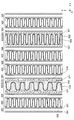
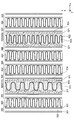
- FIG. 2 shows the internal structure of the cold storage mechanism and the like.
- the cold storage mechanism 500 is provided to reduce the temperature by heat exchange with the refrigerant and maintain a low temperature state.
- not all the cool storage mechanisms 500 have the same configuration, but there are two types of cool storage mechanisms 500 having different configurations.
- one of the cool storage mechanisms 500 is also referred to as “first cool storage mechanism 510”, and the other cool storage mechanism 500 is also referred to as “second cool storage mechanism 520”. .
- the first cool storage mechanism 510 has a configuration in which an inner fin 512 and a cool storage material 513 are housed and sealed in a cool storage container 511.
- the cold storage container 511 is a container formed of metal.
- the cold storage container 511 is formed with a plurality of recesses 514 that recede inward. Of the outer surface of the cold storage container 511, a portion other than the recess 514 is in contact with the tube 300. For this reason, when a low-temperature refrigerant
- coolant when a low-temperature refrigerant
- coolant passes the flow path 301 of the tube 300, the 1st cool storage mechanism 510 will also be cooled by heat exchange with a refrigerant
- the inner fin 512 is formed by bending a metal plate (aluminum) into a wave shape like the corrugated fin 400.
- the top of the corrugated inner fin 512 is in contact with the inner wall surface of the cold storage container 511, specifically, the inner wall surface of the recess 514, and is brazed.
- the cold storage material 513 is a liquid mainly composed of paraffin, and is filled in the cold storage container 511. That is, the space around the inner fin 512 is filled with the cool storage material 513, and the cool storage material 513 is in contact with both the inner wall surface of the cool storage container 511 and the surface of the inner fin 512.
- the heat of the cool storage material 513 is transmitted to the tube 300 through the cool storage container 511. Further, it is also transmitted to the tube 300 through the inner fin 512 and the cold storage container 511. For this reason, when the refrigerant circulates through the refrigeration cycle, the cold storage material 513 is efficiently cooled by heat exchange with the refrigerant to lower the temperature, and at least a part thereof is solidified. In this way, the inner fin 512 functions as a heat transfer promoting material for promoting heat transfer between the refrigerant and the cold storage material.
- the cool storage material 513 at this time is in a solidified state, the cool storage container 511 and the tubes 300 and the corrugated fins 400 arranged in the vicinity thereof are both kept at a low temperature. For this reason, even if the circulation of the refrigerant is stopped, the air passing through the evaporator 10 is cooled. As described above, by arranging the first cold storage mechanism 510, the evaporator 10 can maintain its cooling performance for a while even after shifting to the idle stop state.
- the second cold storage mechanism 520 is configured such that the inner fin 522 and the cold storage material 523 are housed and sealed in the cold storage container 521.
- the structure of the 2nd cool storage mechanism 520 is substantially the same as the structure of the 1st cool storage mechanism 510 demonstrated previously.
- the cold storage container 521 is a container formed of metal. Unlike the cold storage container 511 of the first cold storage mechanism 510, the cold storage container 521 is not formed with a recess, and its surface and substantially the entire inner wall surface are flat. In the portion where the cold storage container 521 and the tube 300 face each other, the entire outer surface of the cold storage container 521 is in contact with the tube 300. For this reason, the contact area between the cold storage container 521 and the tube 300 is wider than the contact area between the cold storage container 511 and the tube 300.
- the cool storage / release performance of the second cool storage mechanism 520 is higher than the cool storage / release performance of the first cool storage mechanism 510.
- the second cool storage mechanism 520 is deprived of more heat than the first cool storage mechanism 510. Therefore, the time required for the cold storage material 523 of the second cold storage mechanism 520 to solidify is shorter than the time required for the cold storage material 513 of the first cold storage mechanism 510 to solidify.
- the inner fin 522 is formed by bending a metal plate (aluminum) into a wave shape, like the corrugated fin 400 and the inner fin 512. Each top portion of the inner fin 522 having a wave shape is in contact with the inner wall surface of the cold storage container 521 and brazed.
- the pitch of the inner fins 522 (the distance between adjacent vertices) is smaller than the pitch of the inner fins 512. For this reason, the contact area between the inner fin 522 and the cool storage material 523 is larger than the contact area between the inner fin 512 and the cool storage material 513. Since the thermal resistance between the cold storage material 523 and the cold storage container 521 is smaller than the thermal resistance between the cold storage material 513 and the cold storage container 511, the cold storage / release performance of the second cold storage mechanism 520 is further enhanced.
- the cold storage material 523 is a liquid mainly composed of paraffin, and is filled in the cold storage container 521.
- the space around the inner fin 522 is filled with the cold storage material 523, and the cold storage material 523 is in contact with both the inner wall surface of the cold storage container 521 and the surface of the inner fin 522.
- the cool storage material 513 and the cool storage material 523 are the same as each other.
- the second cool storage mechanism 520 having the above-described configuration also functions in substantially the same manner as the first cool storage mechanism 510 described above. That is, by performing cold storage in the second cold storage mechanism 520, the evaporator 10 can maintain its cooling performance for a while even after shifting to the idle stop state.
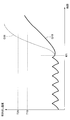
- FIG 3 is a graph showing a change in the temperature of the air blown into the vehicle interior (hereinafter also referred to as “blowing temperature”) when the vehicle shifts to the idle stop state.
- the compressor is operated, and the blowing temperature is maintained substantially constant while pulsating.
- the temperature T10 shown in FIG. 3 is the melting point of the cold storage material 513 and the cold storage material 523.
- the refrigerant temperature and the blowing temperature are sufficiently lower than the temperature T10.
- both the cool storage material 513 and the cool storage material 523 cooled by the refrigerant are in a solidified state. Note that although it varies depending on the overall size of the evaporator 10, the time required from when the compressor is driven until the regenerator material 513 is solidified is approximately 60 seconds.
- the temperature T20 shown in FIG. 3 is an upper limit value of the blowing temperature necessary to maintain the passenger compartment temperature comfortably.
- the line G11 in FIG. 3 shows a change in the blowing temperature when the cold storage mechanism 500 is not present.
- the cold storage mechanism 500 keeps the tube 300 and the corrugated fin 400 at a low temperature.
- the rate of temperature increase after time t01 is moderate. Since the period from the transition to the idle stop state until the blowing temperature exceeds the temperature T20 becomes longer (approximately 60 seconds), the temperature in the passenger compartment can be reduced while continuing the idle stop state for a long time. Can keep comfortable.
- the air conditioner equipped with the evaporator 10 is also operated so as to suppress energy consumption by relatively increasing the blowing temperature.
- energy saving mode operation is also referred to as “energy saving mode operation”.
- the energy saving mode operation intermittent operation of the compressor is performed, and thereby the blowing temperature is made higher than usual.
- the energy saving mode operation is performed, for example, by turning on / off the compressor based on the temperature measured by the thermistor so that the blowing temperature is within a certain range.
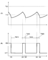
- FIG. 4 (A) is a graph showing the change in the blowing temperature when the energy saving mode operation is performed.
- FIG. 4B is a graph showing changes in the operation (driving state) of the compressor at this time.
- the blowing temperature varies across the temperature T ⁇ b> 10 (melting point of the regenerator material 513 or the like).
- the compressor is stopped during a period TM10 from time t10 to time t20, and the compressor is operated during a period TM20 from time t20 to time t30. Thereafter, the period TM10 and the period TM20 are alternately repeated.
- the period TM20 during which the compressor is driven and the refrigerant is circulated is a relatively short period. Since the cool storage mechanism 500 is cooled only for a short period, it seems that the period TM20 ends before the cool storage material 513 or the like is solidified. However, in this embodiment, as already described, since the cold storage / release performance of the second cold storage mechanism 520 is enhanced, at least the cold storage material 523 of the second cold storage mechanism 520 is solidified during the period TM20.
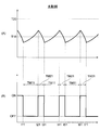
- FIG. 5 shows a graph of an evaporator (comparative example with the present embodiment) in which the cold storage mechanism 500 is not provided.
- FIG. 5A is a graph showing a change in the blowing temperature when the energy saving mode operation is performed.
- FIG. 5B is a graph showing changes in the operation (driving state) of the compressor at this time.
- intermittent operation of the compressor is performed. Specifically, the compressor is stopped in a period TM11 from time t11 to time t21, and the compressor is operated in a period TM21 from time t21 to time t31. Thereafter, the period TM11 and the period TM21 are alternately repeated.
- the change of blowing temperature when the energy saving mode operation is performed is performed. Is the same as that shown in FIG. This is because the first cold storage mechanism 510 has a low temperature storage and discharge performance, and the refrigerant does not solidify in a short period such as the period TM21 (that is, efficient cold storage is not performed).
- the 2nd cool storage mechanism 520 as a part of the cool storage mechanism 500, the raise of the blowing temperature in energy saving mode operation is suppressed and the drive frequency of the compressor is reduced.
- the cool storage material 523 solidified inside the second cool storage mechanism 520 is completely melted in a short period after the transition to the idle stop state. End up. That is, the period during which the cold storage material 523 is solidified is shortened due to the high cold storage / release performance of all the cold storage mechanisms 500. As a result, the period during which the cooling performance of the evaporator 10 is maintained during idle stop is shortened.
- the blowout temperature during the period in which the intermittent operation of the compressor is performed. Both suppression of the rise (FIG. 4) and suppression of the rise of the blowing temperature after shifting to the idle stop state (FIG. 3) are realized.
- FIG. 6 shows the internal structure of the cold storage material or the like.
- the shape of the cold storage container 521 is the same as the shape of the cold storage container 511.
- the cold storage container 521 is formed with a plurality of recesses 524 that recede inward. Of the outer surface of the cold storage container 521, a portion other than the recess 524 is in contact with the tube 300.
- the tops of the wavy inner fins 522 are in contact with the inner wall surface of the cold storage container 521, specifically, the inner wall surface of the recess 524 and are brazed.
- the pitch of the inner fins 522 is the same as the pitch of the inner fins 522 in the first embodiment (FIG. 2). That is, it is smaller than the pitch of the inner fins 512.
- the cool storage material 513 and the cool storage material 523 are the same as each other.
- phase change distance is a distance between a point (for example, point P1 in FIG. 7) farthest from the surface of the inner fin 522 (heat transfer promoting material) of the regenerator 523 and the surface of the inner fin 522. (Distance L1 in FIG. 7).
- the phase change distance of the first cold storage mechanism 510 is similarly defined.
- FIG. 8 shows the relationship between the phase change distance and the cold storage time.
- the “cold storage time” is the time required from the start of cooling by the tube 300 until the cold storage material 523 solidifies. As shown in FIG. 8, the smaller the phase change distance, the shorter the cool storage time. Note that when the graph is drawn with the horizontal axis as the pitch of the inner fins 522, the graph is similar to that shown in FIG.
- the phase change distance in the first cool storage mechanism 510 is in the range of 0.4 mm to 0.75 mm, and the phase change distance in the second cool storage mechanism 520 is 0.4 mm or less.
- the pitch of the inner fins 512 in the first cool storage mechanism 510 is in the range of 1.5 mm to 3 mm, and the pitch of the inner fins 522 in the second cool storage mechanism 520 is 1.5 mm or less.
- the plate thickness of the inner fin 522 may be larger than the plate thickness of the inner fin 512. In this case, since heat conduction in the inner fin 522 is increased, the cool storage / release performance of the second cool storage mechanism 520 is relatively enhanced.
- the inner fin 522 may be formed of a material (for example, carbon) having a higher thermal conductivity than the material of the inner fin 512 (aluminum). Also in this case, since the heat conduction of the inner fin 522 itself is increased, the cool storage / release performance of the second cool storage mechanism 520 is relatively enhanced.
- FIG. 9 shows the internal structure of the cold storage material or the like.
- the pitch of the inner fins 522 in the second cool storage mechanism 520 is the same as the pitch of the inner fins 512 in the first cool storage mechanism 510. That is, the second cool storage mechanism 520 is different from the first cool storage mechanism 510 only in the contact area between the cool storage container 521 and the tube 300. Even if it is such an aspect, there exists an effect similar to 1st Embodiment.
- the shape of the cold storage container 521 is changed as in the present embodiment.
- the shape of the tube 300 in contact with the cold storage container 521 may be changed.
- FIG. 10 shows the internal structure of the cold storage material or the like.
- the shape of the cold storage container 521 is the same as the shape of the cold storage container 521 in the second embodiment (FIG. 6). That is, the cold storage container 521 is formed with a plurality of recesses 524 that recede inward. Of the outer surface of the cold storage container 521, a portion other than the recess 524 is in contact with the tube 300.
- Each of the inner fins 522 stored in the cold storage container 521 has a flat top surface, and each wave has a trapezoidal shape when viewed along the y-axis.
- the top flat surface is in contact with the inner wall surface of the cold storage container 521, specifically, the inner wall surface of the recess 524, and is brazed.
- the contact area between the cool storage container 521 and the inner fin 522 (heat transfer promoting substance) in the second cool storage mechanism 520 is larger than the contact area between the cool storage container 511 and the inner fin 512 in the first cool storage mechanism 510. Yes. Thereby, the heat storage and heat dissipation performance of the second cold storage mechanism 520 is relatively enhanced. Even if it is such an aspect, there exists the same effect as 1st Embodiment.
- the shape of the inner fin 522 as in the present embodiment may be changed.
- the shape and the like of the cool storage container 521 and the inner fins 522 are changed in order to make the cool storage / release performance of the second cool storage mechanism 520 higher than the cool storage / release performance of the first cool storage mechanism 510.
- the material of the regenerator material 523 may be changed.
- the cold storage / release performance of the second cold storage mechanism 520 may be relatively enhanced.
- the higher the thermal conductivity of the regenerator material 523 the higher the regenerator performance and the shorter the regenerator time.
- the thermal conductivity of the regenerator material 513 in the first regenerator mechanism 510 is in the range of 0.1 W / mK to 0.6 W / mK, and the heat conduction of the regenerator material 523 in the second regenerator mechanism 520 is performed.
- the rate is preferably 0.6 W / mK or more.
- the physical property values that are different from each other between the cold storage material 513 and the cold storage material 523 may be other physical property values instead of the thermal conductivity as described above. Examples of such physical property values include melting point and latent heat.
- the higher the melting point of the cool storage material 523 the higher the cool storage / release performance of the second cool storage mechanism 520, resulting in a shorter cool storage time.
- the cool storage performance of the 2nd cool storage mechanism 520 becomes high, so that the cool storage time becomes short, so that the latent heat of the cool storage material 523 becomes small.
- the configuration for relatively enhancing the cold storage / release performance of the second cold storage mechanism 520 is not limited to the configuration described above, and various configurations can be adopted.
- the contact area between the cold storage container 521 and the cold storage material 523 may be made wider than the contact area between the cold storage container 511 and the cold storage material 513 by forming irregularities, fins, or the like on the inner wall surface of the cold storage container 521.
- the cool storage / release performance of the 2nd cool storage mechanism 520 can be made high compared with the cool storage / release performance of the 1st cool storage mechanism 510.
- the fifth embodiment of the present disclosure will be described with reference to FIGS. 12 and 13.
- the fifth embodiment differs from the first embodiment in the shape and arrangement of the first cold storage mechanism 510 and the second cold storage mechanism 520. About another structure, it is the same as 1st Embodiment.
- the first cool storage mechanism 510 and the second cool storage mechanism 520 are not arranged alternately along the x direction as in the previous examples, but the direction in which air passes through the evaporator 10 (y direction). ) Along the line. Specifically, the 2nd cool storage mechanism 520 is arrange
- the cool storage container 511 of the first cool storage mechanism 510 and the cool storage container 521 of the second cool storage mechanism 520 are not separated from each other, and the whole is configured as one container.
- a partition plate 530 is disposed at the center of the container along the y direction. The internal space of the container is divided into two by a partition plate 530. A portion on the ⁇ x direction side from the partition plate is the first cool storage mechanism 510, and a portion on the x direction side from the partition plate is the second cool storage mechanism 520.
- illustration of the inner fins 512 and 522 is omitted.
- a filling portion 515 that protrudes in the y direction is formed in the vicinity of the upper end portion of the side surface of the cold storage container 511 on the y direction side.
- the filling unit 515 is a portion that serves as an inlet of the cold storage material 513 when the cold storage material 513 is filled into the cold storage container 511.
- a filling portion 525 protruding in the ⁇ y direction is formed in the vicinity of the upper end portion of the side surface on the ⁇ y direction side of the cold storage container 521.
- the filling unit 525 is a portion that serves as an inlet of the cold storage material 523 when the cold storage material 523 is filled into the cold storage container 521.
- the pressure loss when the refrigerant passes through the evaporator 10 is relatively large, the refrigerant temperature on the upstream side (the refrigerant inlet side) along the refrigerant flow, and the downstream along the refrigerant flow.
- coolant temperature in the side (refrigerant exit side) is large.
- the evaporator is arranged such that the refrigerant inlet side portion having a relatively high refrigerant temperature is on the leeward side (y direction side) and the refrigerant outlet side portion having a relatively low refrigerant temperature is on the windward side ( ⁇ y direction side). 10 is installed.
- the second cold storage mechanism 520 that needs to store cold in a relatively short period is arranged on the windward side ( ⁇ y direction side) where the refrigerant temperature is low, cold storage in the energy saving mode operation is performed more efficiently.
- the 2nd cool storage mechanism 520 should just be arrange
- the pair of the first cold storage mechanism 510 and the second cold storage mechanism 520 are arranged along the direction in which air passes (y direction). For this reason, compared with the case where these are arranged along x direction like FIG. 2, for example, the ventilation resistance received when air passes the evaporator 10 is suppressed. As a result, it is possible to reduce the size of the blower installed for sending air while maintaining the performance of the evaporator 10.
- the filling portion 525 is configured as a pipe arranged so as to penetrate the partition plate 530 and the cold storage container 511.
- the filling portion 525 has an end on the ⁇ y direction side inserted through a through hole formed in the partition plate 530, and the internal space communicates with the internal space of the cold storage container 521.
- the end part of the y direction side among the filling parts 525 protrudes in the y direction from the side surface of the cold storage container 511 on the y direction side, like the filling part 515.
- the partition plate 530 does not exist, and the cold storage container 511 and the cold storage container 521 are formed as separate containers. Moreover, the position of the upper end part of the cool storage container 511 is lower than the position of the upper end part of the cool storage container 521.
- the filling part 525 is configured as a pipe similar to the example of FIG. 14, but the whole is disposed on the outer side (upper side) of the cold storage container 511.
- the partition plate 530 does not exist, and the internal space of the cold storage container 511 and the internal space of the cold storage container 521 are not separated.
- the portion on the y direction side from the dotted line DL in FIG. 16 is the first cold storage mechanism 510 and the portion on the ⁇ y direction side from the dotted line DL is the second cold storage mechanism 520, but the internal cold storage material (513, 523) Is shared by both parties.
- the internal cold storage material (513, 523) Is shared by both parties.
- only one filling portion 525 is formed and no filling portion 515 is formed because only one inlet of the regenerator material is required.
- the upper end of the partition plate 530 and the top plate of the cold storage containers 511 and 521 are separated.
- the upper end position of the partition plate 530 is lower than the lower end position of the filling portion 515.
- only the filling portion 515 is formed, and the filling portion 525 is not formed.
- the cold storage material 523 may be filled from the filling unit 515 with a syringe or the like.
- the upper end of the partition plate 530 and the top plate of the cold storage containers 511 and 521 are spaced apart from each other as in the example of FIG. 17.
- a top plate 531 extending from the upper end of the partition plate 530 in the y direction is formed.
- the internal space of the cold storage container 511 and the internal space of the cold storage container 521 are completely separated by the partition plate 530 and the top plate 531.
- the filling part 515 is formed below the top plate 531, and the filling part 525 is formed above the top plate 531.
- the partition plate 530 does not exist as in the example of FIG. 15, and the cold storage container 511 and the cold storage container 521 are formed as separate containers, respectively.
- the upper end portion of the cold storage container 511 and the upper end portion of the cold storage container 521 have the same height.
- a specific configuration for arranging the first cold storage mechanism 510 and the second cold storage mechanism 520 along the y direction is as shown in FIG. 13.
- various configurations can be adopted.
- the dimension of the entire cool storage mechanism 500 along the y direction is larger than the dimension of the tube 300 along the y direction. May be. That is, at least one of the first cold storage mechanism 510 or the second cold storage mechanism 520 seems to protrude outward ( ⁇ y direction side or y direction side) from the end of the tube 300 or the corrugated fin. It may be a mode.
- the first cold storage mechanism 510 in the present embodiment is not disposed in the portion of the evaporator 10 where the plurality of tubes 300 are disposed, that is, in the core portion, unlike the previous examples.
- the first cold storage mechanism 510 is disposed at a position adjacent to the lower tank 200 at a position on the outer side ( ⁇ z direction side) than the core portion.
- the 2nd cool storage mechanism 520 in this embodiment is arrange
- the lower tank 200 in this embodiment has a configuration in which two tanks (a first lower tank 201 and a second lower tank 202) having substantially the same shape are arranged so as to be aligned in the y direction. Each tank is arranged with its longitudinal direction along the x-axis. Therefore, a recess 210 along the x axis is formed between the first lower tank 201 and the second lower tank 202 (and on the lower side). The first cold storage mechanism 510 is accommodated in the recess 210.
- the external shape of the 1st cool storage mechanism 510 becomes a shape which can be accommodated in the recessed part 210, and is different from the external shape of the 1st cool storage mechanism 510 in 1st Embodiment etc. However, it is the same as that of 1st Embodiment etc. that the cool storage / release performance is lower than the cool storage / release performance of the 2nd cool storage mechanism 520.
- first cold storage mechanism 510 not all of the cold storage mechanism 500 is arranged in the core part, but a part thereof (first cold storage mechanism 510) is arranged outside the core part. Since the ventilation resistance received when air passes through the evaporator 10 is suppressed, the blower installed for feeding air can be reduced in size while maintaining the performance of the evaporator 10.
- the second cold storage mechanism 520 is arranged in the core portion as in the examples so far. Since the core portion is a portion where the cooling (heat transfer) of the second cold storage mechanism 520 is efficiently performed by the flow of the refrigerant, the cold storage in the energy saving mode operation is efficiently performed.
- the first cold storage mechanism 510 is disposed outside the core portion, but is cooled by the lower tank 200. For this reason, the function of suppressing the rise in the blowing temperature after shifting to the idle stop state is exhibited as before.
- the seventh embodiment of the present disclosure will be described with reference to FIG.
- the seventh embodiment is different from the first embodiment in the shape and arrangement of the first cold storage mechanism 510 and the second cold storage mechanism 520. About another structure, it is the same as 1st Embodiment.
- the first cool storage mechanism 510 and the second cool storage mechanism 520 are arranged in the vertical direction (z direction) in the space between the two adjacent tubes 300. . Specifically, the first cold storage mechanism 510 is disposed on the upper side, and the second cold storage mechanism 520 is disposed on the lower side.
- FIG. 22 shows the temperature change of each part after time t100 when the state is shifted to the idle stop state.
- a line G20 in FIG. 22 is a graph showing a temporal change in the blowing temperature.
- a line G21 in FIG. 22 is a graph showing a temporal change in the temperature of the cold storage material 513 in the first cold storage mechanism 510.
- a line G22 in FIG. 22 is a graph showing a temporal change in the temperature of the cold storage material 523 in the second cold storage mechanism 520.
- the temperature of the regenerator material 513 gradually increases after time t100. Since the cool storage / release performance of the first cool storage mechanism 510 is low, the performance of cooling the surrounding tube 300 and the like is also low. For this reason, immediately after the time t100, the temperature of the regenerator material 513 rises at a relatively large rate as the ambient temperature rises.
- the fact that the cool storage / release performance of the first cool storage mechanism 510 is low means that the time required for all of the internal cool storage material 513 to melt is relatively long. For this reason, the cool storage material 513 continues to cool the surroundings for a long time.
- the temperature of the regenerator material 523 (line G22) also gradually increases after time t100.
- the cool storage / release performance of the second cool storage mechanism 520 is high, the performance of cooling the surrounding tube 300 and the like is also high. For this reason, immediately after the time t100, even if the ambient temperature rises, the cool storage material 523 is kept at a low temperature.
- the fact that the second cold storage mechanism 520 has a high cold storage / release performance means that the time required for all of the internal cold storage material 523 to melt is relatively short. Since the temperature of the cool storage material 513 is increased in a short time, the time for continuously cooling the surroundings is short.
- the temperatures of the cold storage material 513 and the cold storage material 523 change as described above. For this reason, the temperature of the cool storage material 523 is lower than the temperature of the cool storage material 513 at a time t200 in which the period from the transition to the idle stop is relatively short. In addition, at the time t300 in which the period from the transition to the idle stop is relatively long, the temperature of the cold storage material 523 is higher than the temperature of the cold storage material 513.
- the refrigerant changes in the tube 300 from the liquid phase to the gas phase.
- the refrigerant that has become a gas phase on the lower side of the core part moves up the tube 300 toward the upper side, but when cooled in the upper side part, it becomes a liquid phase and moves downward again.
- the liquid phase refrigerant continues to exist for a long period of time, so that an increase in the blowing temperature is suppressed.
- the upper side when a long period of time has passed since the transition to the idle stop (time t30 in FIG. 22), the upper side The temperature becomes lower, and the blowing temperature is suppressed as described above. That is, although the temperature (G22) of the cool storage material 523 is rising, the blowing temperature is maintained in a lower state.
- FIG. The 1st cool storage mechanism 510 should just be arrange
- the second cold storage mechanism 520 may be arranged on the upper side, contrary to FIG.
- the shape of the cold storage container 511 and the shape of the cold storage container 521 are the same as each other, and each has the shape of the cold storage container 511 shown in FIG.
- the shape of the inner fin 512 and the shape of the inner fin 522 are the same as each other, which is the shape of the inner fin 512 shown in FIG. That is, in this embodiment, the structure of the 1st cool storage mechanism 510 and the 2nd cool storage mechanism 520 is mutually the same.
- the cool storage material 513 of the first cool storage mechanism 510 and the cool storage material 523 of the second cool storage mechanism 520 are different from each other.
- Other configurations are the same as those of the first embodiment shown in FIG.
- paraffin (C15) having 15 carbon atoms is used, and its melting point is 9 ° C.
- paraffin (C16) having 16 carbon atoms is used, and the melting point thereof is 17 ° C.
- the melting point of the cold storage material 523 in the second cold storage mechanism 520 is higher than the melting point of the cold storage material 513 in the first cold storage mechanism 510.
- FIG. 23A shows the temperature change of the cold storage material 513 when the first cold storage mechanism 510 according to this embodiment is cooled by the refrigerant in the tube 300.
- the melting point of the regenerator material 513 is shown as a melting point T100.
- the temperature of the regenerator material 513 at the start of cooling at time t0 is shown as the initial temperature T0.
- the temperature of the refrigerant in the tube 300 is indicated as a refrigerant temperature T200.
- the refrigerant temperature T200 is lower than both the initial temperature T0 and the melting point T100.
- the initial temperature T0 is higher than the melting point T100.
- the temperature of the regenerator material 513 gradually decreases and reaches the melting point T100 at time t100.
- the cool storage material 513 begins to solidify from time t100, and the entire cool storage material 513 is solidified at time t200.
- the temperature of the regenerator material 513 is constant (melting point T100).
- the temperature of the cool storage material 513 decreases again.
- FIG. 23B shows the temperature change of the regenerator 523 when the second regenerator 520 according to the present embodiment is cooled by the refrigerant in the tube 300.
- the melting point of the regenerator material 523 is shown as a melting point T110.
- the melting point T110 is higher than the melting point T100.
- the temperature of the regenerator material 523 at the start of cooling at time t0 is shown as the initial temperature T0.
- coolant in the tube 300 is shown as the refrigerant temperature T200.
- the initial temperature T0 and the refrigerant temperature T200 are the same as the initial temperature T0 and the refrigerant temperature T200 shown in FIG. 23A, respectively.
- the melting point T110 is a temperature that is also lower than the initial temperature T0.
- the temperature of the regenerator material 523 gradually decreases after time t0, and reaches the melting point T110 at time t110.
- the cool storage material 523 starts to solidify from time t110, and the entire cool storage material 523 is solidified at time t120.
- the temperature of the regenerator material 523 is constant (melting point T110). After time t120, the temperature of the regenerator material 523 decreases again.
- the temperature difference between the cold storage material 513 and the refrigerant when the cold storage material 513 is solidified is defined as a temperature difference ⁇ T1.
- a temperature difference between the cold storage material 523 and the refrigerant when the cold storage material 523 is solidified is defined as a temperature difference ⁇ T2.
- the temperature difference ⁇ T2 is larger than the temperature difference ⁇ T1.
- the speed at which heat is taken from the cold storage material 523 in the period TM2 is higher than the speed at which heat is taken from the cold storage material 513 in the period TM1.
- the length of the period TM2 is shorter than the length of the period TM1.
- the cold storage material 523 solidifies faster than the cold storage material 513. That is, the cool storage / release performance of the second cool storage mechanism 520 is higher than the cool storage / release performance of the first cool storage mechanism 510. As a result, the same effects as those of the first embodiment are obtained.
- a material different from the above may be used as each specific material of the cool storage material 513 and the cool storage material 523.
- the ninth embodiment of the present disclosure will be described with reference to FIGS. 24A and 24B.
- the shape of the cold storage container 511 and the shape of the cold storage container 521 are the same as each other, and each has the shape of the cold storage container 511 shown in FIG.
- the shape of the inner fin 512 and the shape of the inner fin 522 are the same as each other, which is the shape of the inner fin 512 shown in FIG. That is, in this embodiment, the structure of the 1st cool storage mechanism 510 and the 2nd cool storage mechanism 520 is mutually the same.
- the shape of the tube 300 in a part is different from the case of the first embodiment.
- Other configurations are the same as those of the first embodiment shown in FIG.
- FIG. 24A shows a cross-sectional view when the tube 300A is cut along a plane perpendicular to the refrigerant flow direction.
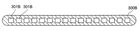
- FIG. 24B shows a cross-sectional view when the tube 300B is cut along a plane perpendicular to the refrigerant flow direction.
- Both the tube 300A and the tube 300B are formed by extrusion molding of aluminum.
- a plurality of flow paths 301 (hereinafter referred to as “flow paths 301 ⁇ / b> A”) formed in the tube 300 ⁇ / b> A are formed in the tube 300 ⁇ / b> A, and each cross-sectional shape is rectangular.
- Each flow path 301A is arranged in a line at a constant pitch.
- flow paths 301B a plurality of flow paths 301 (hereinafter referred to as “flow paths 301B”) formed in the tube 300B are formed in the tube 300B, and each cross-sectional shape is rectangular.
- Each flow path 301B is arranged in a line at a constant pitch.
- the channel cross-sectional area of each channel 301B is smaller than the channel cross-sectional area of each channel 301A.
- the arrangement pitch of the flow paths 301B is narrower than the arrangement pitch of the flow paths 301A. Comparing the tube 300A and the tube 300B, the contact area between the flow path 301B and the refrigerant is larger than the contact area between the flow path 301A and the refrigerant.
- the heat storage / heat dissipation performance of the second cold storage mechanism 520 is relatively higher than the heat storage / heat dissipation performance of the first cold storage mechanism 510. Even if it is such an aspect, there exists an effect similar to 1st Embodiment.
- the “contact area between the flow path 301B and the refrigerant” is an area obtained by adding up the area of the inner surface of the flow path 301B for all the flow paths 301B formed in one tube 300B. .
- the “contact area between the channel 301 ⁇ / b> A and the refrigerant” is similarly defined.
- FIGS. 25A and 25B A modification of the ninth embodiment described above will be described with reference to FIGS. 25A and 25B. Also in this modification, the shape of the cool storage container 511 and the shape of the cool storage container 521 are the same, and each has the shape of the cool storage container 511 shown in FIG. Further, the shape of the inner fin 512 and the shape of the inner fin 522 are the same as each other, which is the shape of the inner fin 512 shown in FIG.
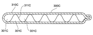
- FIG. 25A shows a cross-sectional view when the tube 300C is cut along a plane perpendicular to the refrigerant flow direction.
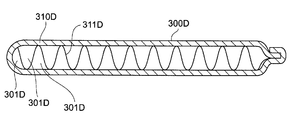
- FIG. 25B shows a cross-sectional view when the tube 300D is cut along a plane perpendicular to the refrigerant flow direction.
- the tube 300C has a container 310C and fins 311C.
- the container 310C is a container formed by bending a metal plate and crimping an end portion thereof, and has a flat cross section.
- the fin 311C is formed by bending a metal plate (aluminum) into a wave shape, similar to the corrugated fin 400.
- the top of the corrugated fin 311C is in contact with the inner wall surface of the container 310C and is brazed.
- the internal space of the container 310C is partitioned into a plurality of spaces by the fins 311C. Each space serves as a flow path 301C through which the refrigerant flows.
- the tube 300D has the same configuration as described above.
- the tube 300D has a container 310D and fins 311D.
- the container 310D is a container formed by bending a metal plate and crimping an end portion thereof, and has a flat cross section.
- the fin 311D is formed by bending a metal plate (aluminum) into a wave shape, similar to the corrugated fin 400.
- the top of the corrugated fin 311D is in contact with the inner wall surface of the container 310D and brazed.
- the internal space of the container 310D is partitioned into a plurality of spaces by the fins 311D. Each space serves as a flow path 301D through which the refrigerant flows.
- the pitch of the fins 311D that is, the interval between the tops adjacent to each other in the fin 311D is narrower than the pitch of the fins 311C, that is, the interval between the tops adjacent to each other in the fin 311C.
- the contact area between the flow path 301D and the refrigerant is larger than the contact area between the flow path 301C and the refrigerant.
- the heat storage / heat dissipation performance of the second cold storage mechanism 520 is relatively higher than the heat storage / heat dissipation performance of the first cold storage mechanism 510. Even if it is such an aspect, there exists an effect similar to 1st Embodiment.
Landscapes
- Engineering & Computer Science (AREA)
- Physics & Mathematics (AREA)
- Mechanical Engineering (AREA)
- Thermal Sciences (AREA)
- General Engineering & Computer Science (AREA)
- Air-Conditioning For Vehicles (AREA)
Abstract
蒸発器(10)は、蓄冷容器(511、521)の内部に収納された蓄冷材(513、523)の温度を冷媒との熱交換により低下させる複数の蓄冷機構(500)、を備えている。複数の蓄冷機構は、第1蓄冷機構(510)と、第1蓄冷機構よりも蓄放熱性能が高い第2蓄冷機構(520)と、を備えている。これにより、コンプレッサの間欠動作が行われている期間における空気の温度上昇を抑制し、且つ、アイドルストップの状態に移行した後における空気の温度上昇をも抑制することができる。
Description
本出願は、当該開示内容が参照によって本出願に組み込まれた、2015年4月30日に出願された日本特許出願2015-092589および、2016年4月12日に出願された日本特許出願2016-079306を基にしている。
本開示は、内部を通る冷媒との熱交換により空気を冷却する蒸発器に関する。
空調装置における冷凍サイクルの一部として用いられる蒸発器は、液相の冷媒を内部で蒸発させてその温度を低下させ、当該冷媒との熱交換によって空気を冷却するものである。
車両用の空調装置においては、内燃機関の駆動力によってコンプレッサを動作させ、これにより冷媒を循環させている。このため、内燃機関が停止している状態においては冷媒の循環が停止した状態となるので、蒸発器を通過する空気の冷却を行うことができなくなる。
近年、一時停止の際において自動的に内燃機関を停止させる、所謂アイドルストップを行う車両が普及している。このような車両では、運転中において比較的頻繁に内燃機関が停止し、その度にコンプレッサが停止する。その際、上記のように空気の冷却が行われなくなってしまうと、車室内の温度が上昇し乗員に不快感を与えてしまうこととなる。
そこで、蓄冷機構を備えた構成の蒸発器が提案されており、既に実用化されている(例えば、下記特許文献1を参照)。蓄冷機構とは、容器の内部にパラフィン等の蓄冷材が収納されたものであって、蒸発器のうち冷媒が通るチューブ等に接した状態で配置されるものである。
内燃機関の駆動力によりコンプレッサが動作しているときには、蒸発器で低温となった冷媒との熱交換により蓄冷機構(蓄冷容器)が冷却され、蓄冷容器の内部に収納された蓄冷材が凝固する。
その後、アイドルストップが行われて冷媒の循環が停止した状態となっても、凝固した蓄冷材により、蓄冷機構やその近傍のチューブ等は低温に維持される。このため、蒸発器を通過して車室内に吹き出される空気の冷却を、しばらくの間は継続して行うことが可能となる。
アイドルストップの状態ではない通常の運転中においては、空調装置のコンプレッサを連続的に動作させるのではなく、間欠的に動作させる場合がある。このような間欠動作は、蒸発器の温度低下を抑制し霜の付着を防止することや、コンプレッサの動作に必要なエネルギーを低減し省エネを実現すること等を目的として行われる。
間欠動作が行われている際には、コンプレッサが動作して蓄冷材の温度が低下する期間と、コンプレッサが停止して蓄冷材の温度が上昇する期間とが、交互に繰り返されることとなる。この場合、蓄冷材が冷却される期間は比較的短く、蓄冷材が完全に凝固しないので、蓄冷機構における蓄冷が十分には行われない。その結果、空調装置から車室内に吹き出される空気の温度上昇を抑制することができなくなってしまう。
そこで、蓄冷機構の蓄放冷性能を高くすることが考えられる。蓄放冷性能とは、蓄冷機構が外部と熱のやり取りをする際における熱の伝わりやすさ、すなわち、蓄冷機構とその外部との間における熱伝導又は熱伝達の大きさのことである。蓄冷機構の蓄放冷性能を高くすると、コンプレッサの動作中には短期間のうちに多くの熱が蓄冷材から奪われる。このため、上記のような間欠動作が行われる場合でも、蓄冷材は十分にその温度を低下させ、凝固する。これにより、アイドルストップが行われていない期間(間欠動作中)においては、車室内に吹き出される空気の温度上昇は抑制される。
しかしながら、アイドルストップの状態になると、(蓄冷機構の蓄放冷性能が高いので)短期間のうちに多く熱が蓄冷材に加えられ、蓄冷材の全てがすぐに融解してしまう。このため、車室内に吹き出される空気は、アイドルストップの状態に移行した直後においては低温となるのであるが、すぐにその温度が上昇してしまう。
このように、コンプレッサの間欠動作が行われている期間における空気の温度上昇を抑制することと、アイドルストップの状態に移行した後の空気の温度上昇を抑制することとを、両立させることは困難であった。
本開示はこのような点に鑑みてなされたものであり、その目的は、コンプレッサの間欠動作が行われている期間における空気の温度上昇を抑制し、且つ、アイドルストップの状態に移行した後における空気の温度上昇をも抑制することのできる蒸発器を提供することにある。
本開示の第1態様によると、蒸発器は、内部を通る冷媒との熱交換により空気を冷却する。蒸発器は、蓄冷容器の内部に収納された蓄冷材の温度を冷媒との熱交換により低下させる蓄冷機構、を複数備えている。蒸発器は、蓄冷機構の1つである第1蓄冷機構と、蓄冷機構の1つであって、第1蓄冷機構よりも蓄放熱性能が高い第2蓄冷機構と、を備える。
本開示の第2態様によると、蒸発器は、内部を通る冷媒との熱交換により空気を冷却する。蒸発器は、前記冷媒が内部を通る複数のチューブと、互いに隣り合う前記チューブの間に保持されており、その温度を前記冷媒との熱交換により低下させる複数の蓄冷機構と、を備える。蒸発器は、前記蓄冷機構の1つである第1蓄冷機構と、前記蓄冷機構の1つであって、前記第1蓄冷機構よりも蓄放熱性能が高い第2蓄冷機構と、を備える。
本開示の第3態様によると、蒸発器は、内部を通る冷媒との熱交換により空気を冷却する。蒸発器は、蓄冷容器の内部に収納された蓄冷材の温度を冷媒との熱交換により低下させる複数の蓄冷機構、を備えている。複数の蓄冷機構は、第1蓄冷機構と、第1蓄冷機構よりも蓄放熱性能が高い第2蓄冷機構と、を備える。
本開示の第4態様によると、蒸発器は、内部を通る冷媒との熱交換により空気を冷却する。蒸発器は、冷媒が内部を通る複数のチューブと、互いに隣り合うチューブの間に保持されており、その温度を冷媒との熱交換により低下させる複数の蓄冷機構と、を備えている。複数の蓄冷機構は、第1蓄冷機構と、第1蓄冷機構よりも蓄放熱性能が高い第2蓄冷機構と、を備える。
蓄放熱性能が比較的低い第1蓄冷機構では、アイドルストップの状態に移行した後、凝固した蓄冷材の温度がゆっくりと上昇する。換言すれば、蓄冷材が低温となっている状態が長時間維持される。このため、アイドルストップの状態に移行した後の空気の温度上昇を、長時間に亘って抑制することができる。
蓄放熱性能が比較的高い第2蓄冷機構では、コンプレッサの間欠動作が行われている期間において、コンプレッサが動作する短時間のうちに蓄冷材の温度が低下する。このため、少なくとも第2蓄冷機構においては十分な蓄冷が行われるので、車室内に吹き出される空気の温度上昇が抑制される。
このように、本開示においては、蓄放冷性能が互いに異なる複数の蓄冷容器を備えることにより、コンプレッサの間欠動作が行われている期間における空気の温度上昇を抑制することと、アイドルストップの状態に移行した後における空気の温度上昇を抑制することと、の両立を実現することができる。
本開示によれば、コンプレッサの間欠動作が行われている期間における空気の温度上昇を抑制し、且つ、アイドルストップの状態に移行した後の空気の温度上昇をも抑制することのできる蒸発器が提供される。
以下に、図面を参照しながら本開示を実施するための複数の形態を説明する。各形態において先行する形態で説明した事項に対応する部分には同一の参照符号を付して重複する説明を省略する場合がある。各形態において構成の一部のみを説明している場合は、構成の他の部分については先行して説明した他の形態を適用することができる。各実施形態で具体的に組合せが可能であることを明示している部分同士の組合せばかりではなく、特に組合せに支障が生じなければ、明示してなくとも実施形態同士を部分的に組み合せることも可能である。
(第1実施形態)
本開示の第1実施形態について図1~5を参照して説明する。図1に示される蒸発器10は、車両の空調システムとして構成された冷凍サイクル(不図示)の一部を成す蒸発器(エバポレータ)である。蒸発器10には、冷凍サイクルの一部に配置された不図示のコンプレッサにより冷媒が送り込まれる。コンプレッサは、車両に備えられた内燃機関の駆動力により動作する。蒸発器10は、送り込まれた冷媒を内部で蒸発させながら、冷媒と空気との熱交換を行うことにより空気を冷却するものである。
本開示の第1実施形態について図1~5を参照して説明する。図1に示される蒸発器10は、車両の空調システムとして構成された冷凍サイクル(不図示)の一部を成す蒸発器(エバポレータ)である。蒸発器10には、冷凍サイクルの一部に配置された不図示のコンプレッサにより冷媒が送り込まれる。コンプレッサは、車両に備えられた内燃機関の駆動力により動作する。蒸発器10は、送り込まれた冷媒を内部で蒸発させながら、冷媒と空気との熱交換を行うことにより空気を冷却するものである。
図1を参照しながら、蒸発器10の構成について説明する。蒸発器10は、上部タンク100と、下部タンク200と、チューブ300と、コルゲートフィン400と、蓄冷機構500と、を備えている。
上部タンク100は、蒸発器10に対して供給された冷媒を一時的に貯留し、当該冷媒をチューブ300に供給するための容器である。上部タンク100は、細長い棒状の容器として形成されている。上部タンク100は、その長手方向を水平方向に沿わせた状態で、蒸発器10のうち上方側部分に配置されている。
下部タンク200は、上部タンク100と略同一形状の容器である。下部タンク200は、上部タンク100からチューブ300を通って来た冷媒を受け入れるものである。下部タンク200は、上部タンク100と同様にその長手方向を水平方向に沿わせた状態で、蒸発器10のうち下方側部分に配置されている。
チューブ300は、扁平形状の断面を有する細長い配管であって、蒸発器10に複数備えられている。チューブ300の内部には、その長手方向に沿った流路301(図1では不図示)が複数形成されている。それぞれのチューブ300は、その長手方向を鉛直方向に沿わせており、互いの主面を対向させた状態で積層配置されている。積層された複数のチューブ300が並ぶ方向は、上部タンク100の長手方向と同じである。
それぞれのチューブ300は、その一端が上部タンク100に接続されており、その他端が下部タンク200に接続されている。このような構成により、上部タンク100の内部空間と、下部タンク200の内部空間とは、それぞれのチューブ300内の流路301によって連通されている。
冷媒は、チューブ300の内部を通って上部タンク100から下部タンク200へと移動する。その際、蒸発器10を通過する空気との間で熱交換が行われ、これにより冷媒は液相から気相へと変化する。また、空気は冷媒との熱交換により熱を奪われて、その温度を低下させる。
コルゲートフィン400は、金属板を波状に折り曲げることにより形成されたものである。コルゲートフィン400は、波形状を有する金属板を有する。コルゲートフィン400は、それぞれのチューブ300の間に配置されている。波状であるコルゲートフィン400のそれぞれの頂部は、チューブ300の外表面に対して当接しており、且つろう接されている。このため、蒸発器10を通過する空気の熱は、チューブ300を介して冷媒に伝達されるだけでなく、コルゲートフィン400及びチューブ300を介しても冷媒に伝達される。つまり、コルゲートフィン400によって空気との接触面積が大きくなっており、冷媒と空気との熱交換が効率よく行われる。
コルゲートフィン400は、互いに隣り合う2本のチューブ300の間に形成された空間(後述の蓄冷機構500が配置されている部分を除く)の全体、すなわち、上部タンク100から下部タンク200に至るまでの全範囲に亘って配置されている。ただし、図1においてはその一部のみが図示されており、他の部分については図示が省略されている。
尚、上部タンク100の内部空間、及び下部タンク200の内部空間が仕切り板によって複数に区分された構成とした上で、上部タンク100と下部タンク200との間を冷媒が往復しながら(双方向に)流れるような態様としてもよい。本開示を実施するにあたっては、冷媒が通る経路は特に限定されない。
図1においては、上部タンク100の長手方向であって、図1の左側から右側に向かう方向をx方向としてx軸を設定している。また、蒸発器10を空気が通過する方向であって、図1の紙面奥側から手前側に向かう方向をy方向としてy軸を設定している。更に、下部タンク200から上部タンク100へと向かう方向をz方向としてz軸を設定している。以降の図面においても、同様にしてx軸、y軸、z軸を設定している。
蓄冷機構500は、冷媒が循環しているときに蓄冷を行い、冷媒の循環が停止した後においてもチューブ300等を低温に保つためのものである。蓄冷機構500は、細長い棒状の部材として形成されている。蓄冷機構500は、その長手方向をz方向に沿わせた状態で、互いに隣り合う2本のチューブ300の間となる位置に配置され、それぞれのチューブ300によって保持されている。
図1に示されるように、チューブ300とチューブ300との間に形成された複数の空間には、その一部にコルゲートフィン400が配置されており、他の一部に蓄冷機構500が配置されている。本実施形態では、左側からコルゲートフィン400、コルゲートフィン400、蓄冷機構500、の順となるよう、これらが規則的に配置されている。しかしながら、本開示を実施するにあたっては、コルゲートフィン400と蓄冷機構500との相対的な位置関係や、これらの配置における規則性の有無は特に限定されない。
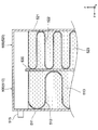
図2を参照しながら、蓄冷機構500の具体的な構成について説明する。図2は蓄冷機構等の内部構造を示している。蓄冷機構500は、冷媒との熱交換によってその温度を低下させ、低温となっている状態を維持するために設けられたものである。本実施形態では、全ての蓄冷機構500が同一の構成となっているのではなく、互いに構成の異なる2種類の蓄冷機構500が存在している。これらを区別するために、以下の説明においては、一方の蓄冷機構500のことを「第1蓄冷機構510」とも表記し、他方の蓄冷機構500のことを「第2蓄冷機構520」とも表記する。
先ず、第1蓄冷機構510の構成について説明する。第1蓄冷機構510は、蓄冷容器511の内部に、インナーフィン512と、蓄冷材513とが収納され密封された構成となっている。
蓄冷容器511は金属により形成された容器である。蓄冷容器511には、内側に向けて後退している凹部514が複数形成されている。蓄冷容器511の外側面のうち、凹部514以外の部分は、チューブ300に対して当接している。このため、チューブ300の流路301を低温の冷媒が通ると、冷媒との熱交換によって第1蓄冷機構510も冷却される。
インナーフィン512は、コルゲートフィン400と同様に、金属板(アルミニウム)を波状に折り曲げることにより形成されたものである。波状であるインナーフィン512の頂部は、蓄冷容器511の内壁面、具体的には凹部514の内壁面に対して当接しており、且つろう接されている。
蓄冷材513は、パラフィンを主成分とする液体であり、蓄冷容器511の内部に充填されている。つまり、インナーフィン512の周囲の空間は蓄冷材513で満たされており、蓄冷材513が、蓄冷容器511の内壁面及びインナーフィン512の表面のいずれに対しても接した状態となっている。
チューブ300によって蓄冷容器511が冷却されると、蓄冷材513の熱は蓄冷容器511を介してチューブ300に伝達される。また、インナーフィン512及び蓄冷容器511を介してもチューブ300に伝達される。このため、冷凍サイクルを冷媒が循環しているときにおいては、蓄冷材513は冷媒との熱交換によって効率的に冷却されて温度を低下させ、少なくともその一部が凝固した状態となる。このように、インナーフィン512は、冷媒と蓄冷材との間における伝熱を促進するための伝熱促進物として機能する。
車両がアイドルストップの状態になると、冷凍サイクルのコンプレッサが停止した状態となる。このため、冷凍サイクルにおける冷媒の循環は行われなくなり、蒸発器10における冷媒の蒸発も行われなくなる。
しかしながら、このときの蓄冷材513は凝固した状態となっているので、蓄冷容器511、及びその近傍に配置されているチューブ300やコルゲートフィン400は、いずれも低温に維持されている。このため、冷媒の循環が停止していても、蒸発器10を通過する空気は冷却される。このように、第1蓄冷機構510が配置されていることにより、アイドルストップの状態に移行した後においても、蒸発器10はその冷却性能をしばらくの間維持することができる。
続いて、第2蓄冷機構520の構成について説明する。第2蓄冷機構520は、蓄冷容器521の内部に、インナーフィン522と、蓄冷材523とが収納され密封された構成となっている。このように、第2蓄冷機構520の構成は、先に説明した第1蓄冷機構510の構成と概ね同一となっている。
蓄冷容器521は金属により形成された容器である。第1蓄冷機構510の蓄冷容器511とは異なり、蓄冷容器521には凹部が形成されておらず、その表面及び内壁面の略全体が平坦となっている。蓄冷容器521とチューブ300とが対向する部分においては、蓄冷容器521の外表面の全体がチューブ300に対して当接している。このため、蓄冷容器521とチューブ300との接触面積は、蓄冷容器511とチューブ300との接触面積よりも広くなっている。
その結果、第2蓄冷機構520の蓄放冷性能は、第1蓄冷機構510の蓄放冷性能よりも高くなっている。チューブ300によって冷却された際には、第2蓄冷機構520の方が、第1蓄冷機構510よりも多くの熱を奪われる。従って、第2蓄冷機構520の蓄冷材523が凝固するまでに要する時間は、第1蓄冷機構510の蓄冷材513が凝固するまでに要する時間よりも短い。
インナーフィン522は、コルゲートフィン400やインナーフィン512と同様に、金属板(アルミニウム)を波状に折り曲げることにより形成されたものである。波状であるインナーフィン522のそれぞれの頂部は、蓄冷容器521の内壁面に対して当接しており、且つろう接されている。
図2に示されるように、インナーフィン522のピッチ(隣り合う頂点間の距離)は、インナーフィン512のピッチよりも小さくなっている。このため、インナーフィン522と蓄冷材523との接触面積は、インナーフィン512と蓄冷材513との接触面積よりも広くなっている。蓄冷材523と蓄冷容器521との間における熱抵抗は、蓄冷材513と蓄冷容器511との間における熱抵抗よりも小さいので、第2蓄冷機構520の蓄放冷性能は更に高くなっている。
蓄冷材523は、パラフィンを主成分とする液体であり、蓄冷容器521の内部に充填されている。インナーフィン522の周囲の空間は蓄冷材523で満たされており、蓄冷材523が、蓄冷容器521の内壁面及びインナーフィン522の表面のいずれに対しても接した状態となっている。本実施形態においては、蓄冷材513と蓄冷材523とは互いに同一である。
以上のような構成の第2蓄冷機構520も、先に説明した第1蓄冷機構510と概ね同様に機能する。つまり、第2蓄冷機構520における蓄冷が行われることにより、アイドルストップの状態に移行した後においても、蒸発器10はその冷却性能をしばらくの間維持することができる。
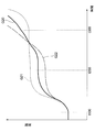
図3の線G10は、車両がアイドルストップの状態に移行した際における、車室内に吹き出される空気の温度(以下、「吹き出し温度」とも称する)の変化を示すグラフである。アイドルストップの状態となる時刻t01よりも前の期間においては、コンプレッサの運転が行われており、吹き出し温度は脈動しながらも概ね一定に維持されている。
図3に示された温度T10は、蓄冷材513及び蓄冷材523の融点である。時刻t01よりも前の期間においては、冷媒の温度及び吹き出し温度は、温度T10よりも十分に低い温度となっている。このため、冷媒によって冷却される蓄冷材513及び蓄冷材523は、いずれも凝固した状態となっている。尚、蒸発器10の全体の大きさによっても変化するのであるが、コンプレッサが駆動されてから蓄冷材513等が凝固した状態となるまでに要する時間は、概ね60秒程度である。
時刻t01以降においては、アイドルストップの状態となるため、冷媒の循環が行われない。その結果、冷媒の温度及び吹き出し温度は次第に上昇して行く。図3に示された温度T20は、車室内の気温を快適に維持するために必要な吹き出し温度の上限値である。吹き出し温度が温度T20以上になると、アイドルストップを中断し、内燃機関が自動的に駆動される。
図3の線G11で示されているのは、蓄冷機構500が存在しない場合における吹き出し温度の変化である。本実施形態(線G10)では、蓄冷機構500によってチューブ300やコルゲートフィン400が低温に保たれる。このため、蓄冷機構500が存在しない場合(線G11)に比べると、時刻t01以降における温度上昇の速度が緩やかとなっている。アイドルストップの状態に移行してから、吹き出し温度が温度T20を超えてしまうまでの期間が長くなる(概ね60秒程度)ので、アイドルストップの状態を長期間継続しながらも、車室内の気温を快適に保つことができる。
蒸発器10が搭載された空調装置では、吹き出し温度を比較的高くすることによりエネルギーの消費を抑制するような運転も行われる。このような運転を、以下では「省エネモード運転」とも称する。
省エネモード運転においては、コンプレッサの間欠運転が行われ、これにより吹き出し温度が通常よりも高くされる。省エネモード運転は、例えば、吹き出し温度が一定の範囲に収まるよう、サーミスタによる測定温度に基づいてコンプレッサをON/OFFさせることにより行われる。
図4(A)は、省エネモード運転が行われているときにおける、吹き出し温度の変化を示すグラフである。図4(B)は、このときのコンプレッサの動作(駆動状態)の変化を示すグラフである。図4に示される例では、吹き出し温度は温度T10(蓄冷材513等の融点)をまたいで変動している。
この例では、図4(B)に示されるように、時刻t10から時刻t20までの期間TM10においてコンプレッサが停止しており、時刻t20から時刻t30までの期間TM20においてコンプレッサの運転が行われている。以降は、このような期間TM10と期間TM20とが交互に繰り返される。
コンプレッサが駆動され、それに伴い冷媒の循環が行われる期間TM20は、比較的短い期間となっている。蓄冷機構500は短い期間しか冷却されないので、蓄冷材513等が凝固しないうちに期間TM20が終了してしまうようにも思われる。しかしながら、本実施形態では、既に述べたように第2蓄冷機構520の蓄放冷性能が高められているので、少なくとも第2蓄冷機構520の蓄冷材523は、期間TM20の間において凝固する。
つまり、第2蓄冷機構520においては、期間TM20での蓄冷が効率的に行われる。続く期間TM10ではコンプレッサが停止しているのであるが、蓄冷の効果により吹き出し温度の上昇速度は緩やかとなる。その結果、次にコンプレッサが駆動されるまでの期間TM10の長さは、比較的長くなる。
図5には、蓄冷機構500が備えられていない蒸発器(本実施形態との比較例)におけるグラフが示されている。図5(A)は、省エネモード運転が行われているときにおける、吹き出し温度の変化を示すグラフである。図5(B)は、このときのコンプレッサの動作(駆動状態)の変化を示すグラフである。
図5の例でも、コンプレッサの間欠運転が行われている。具体的には、時刻t11から時刻t21までの期間TM11においてコンプレッサが停止しており、時刻t21から時刻t31までの期間TM21においてコンプレッサの運転が行われている。以降は、このような期間TM11と期間TM21とが交互に繰り返される。
この比較例においては、蓄冷機構が存在しないので、期間TM21における蓄冷が行われない。従って、コンプレッサが停止した時刻(t31等)以降においては、吹き出し温度は素早く上昇してしまう。その結果、期間TM11は図4の期間TM10よりも短くなっており、コンプレッサの駆動が頻繁に行われている。図4と図5を比較すると明らかなように、本実施形態では、蓄冷機構500(特に第2蓄冷機構520)を備えることにより、コンプレッサの駆動頻度が低減され、省エネが実現されている。
尚、蒸発器10が第2蓄冷機構520を備えておらず、蓄冷機構500の全てが第1蓄冷機構510であるような場合には、省エネモード運転が行われているときにおける吹き出し温度の変化は図5(A)に示されるものと同様となる。これは、第1蓄冷機構510の蓄放冷性能が低く、期間TM21のような短期間では冷媒が凝固しない(つまり、効率的な蓄冷が行われない)からである。
このように、本実施形態では、蓄冷機構500の一部として第2蓄冷機構520を備えることにより、省エネモード運転における吹き出し温度の上昇が抑制され、コンプレッサの駆動頻度が低減されている。
ところで、上記に鑑みれば、蓄冷機構500の全てを第2蓄冷機構520とした方がよいようにも思われる。しかしながら、第1蓄冷機構510が1つも備えられていない場合には、第2蓄冷機構520の内部で凝固している蓄冷材523が、アイドルストップの状態に移行した以降において短期間で全て融解してしまう。つまり、全ての蓄冷機構500の蓄放冷性能が高いことに起因して、蓄冷材523が凝固した状態となっている期間が短くなってしまう。その結果、アイドルストップの際に蒸発器10の冷却性能が維持される期間が短くなってしまう。
以上のように、本実施形態では、蓄放冷性能が互いに異なる第1蓄冷機構510と第2蓄冷機構520との両方を備えることにより、コンプレッサの間欠動作が行われている期間における吹き出し温度の上昇の抑制(図4)、及び、アイドルストップの状態に移行した後における吹き出し温度の上昇の抑制(図3)、の両方が実現されている。
(第2実施形態)
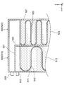
図6を参照しながら、本開示の第2実施形態について説明する。第2実施形態においては、第2蓄冷機構520の構成についてのみ第1実施形態と異なっており、他の構成については第1実施形態と同一である。図6は、蓄冷材等の内部構造を示している。
図6を参照しながら、本開示の第2実施形態について説明する。第2実施形態においては、第2蓄冷機構520の構成についてのみ第1実施形態と異なっており、他の構成については第1実施形態と同一である。図6は、蓄冷材等の内部構造を示している。
本実施形態では、蓄冷容器521の形状が、蓄冷容器511の形状と同一となっている。蓄冷容器521には、内側に向けて後退している凹部524が複数形成されている。蓄冷容器521の外側面のうち、凹部524以外の部分は、チューブ300に対して当接している。
蓄冷容器521の内部において、波状であるインナーフィン522の頂部は、蓄冷容器521の内壁面、具体的には凹部524の内壁面に対して当接しており、且つろう接されている。インナーフィン522のピッチは、第1実施形態(図2)におけるインナーフィン522のピッチと同一となっている。すなわち、インナーフィン512のピッチよりも小さくなっている。本実施形態でも、蓄冷材513と蓄冷材523とは互いに同一である。
このように、第1蓄冷機構510及び第2蓄冷機構520において、それぞれのインナーフィンのピッチのみを互いに異ならせ、これにより第2蓄冷機構520の蓄放冷性能を相対的に高めることによっても、第1実施形態と同様の効果を奏する。
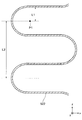
尚、インナーフィン522のピッチを小さくした場合に第2蓄冷機構520の蓄放冷性能が高くなる理由としては、インナーフィン522と蓄冷材523との接触面積が広くなることのほか、蓄冷容器521内における相変化距離が小さくなることも挙げられる。「相変化距離」とは、蓄冷材523のうちインナーフィン522(伝熱促進物)の表面から最も離れている点(例えば図7の点P1)と、インナーフィン522の表面との間の距離(図7の距離L1)、のことである。第1蓄冷機構510の相変化距離についても同様に定義される。
このような相変化距離が小さいと、第2蓄冷機構520の蓄放冷性能は更に高くなり、蓄冷材523の凝固がより短時間で行われることとなる。図8には、相変化距離と蓄冷時間との関係が示されている。「蓄冷時間」とは、チューブ300による冷却が開始されてから蓄冷材523が凝固するまでに要する時間のことである。図8に示されるように、相変化距離が小さくなるほど、蓄冷時間も短くなる。尚、横軸をインナーフィン522のピッチとしてグラフを描いた場合にも、図8に示されるものと同様のグラフとなる。
本開示を実施するにあたっては、第1蓄冷機構510における相変化距離を0.4mmから0.75mmの範囲内とし、第2蓄冷機構520における相変化距離を0.4mm以下とすることが望ましい。また、第1蓄冷機構510におけるインナーフィン512のピッチを1.5mmから3mmの範囲内とし、第2蓄冷機構520におけるインナーフィン522のピッチを1.5mm以下とすることが望ましい。
尚、インナーフィン522の板厚をインナーフィン512の板厚よりも大きくしてもよい。この場合、インナーフィン522の内部における熱伝導が大きくなるので、第2蓄冷機構520の蓄放冷性能が相対的に高められる。
また、インナーフィン512の材料(アルミニウム)よりも熱伝導率の大きい材料(例えばカーボン)で、インナーフィン522が形成されていてもよい。この場合にも、インナーフィン522自体の熱伝導が大きくなるので、第2蓄冷機構520の蓄放冷性能が相対的に高められる。
(第3実施形態)
図9を参照しながら、本開示の第3実施形態について説明する。第3実施形態においても、第2蓄冷機構520の構成についてのみ第1実施形態と異なっており、他の構成については第1実施形態と同一である。図9は、蓄冷材等の内部構造を示している。
図9を参照しながら、本開示の第3実施形態について説明する。第3実施形態においても、第2蓄冷機構520の構成についてのみ第1実施形態と異なっており、他の構成については第1実施形態と同一である。図9は、蓄冷材等の内部構造を示している。
本実施形態では、第2蓄冷機構520におけるインナーフィン522のピッチが、第1蓄冷機構510におけるインナーフィン512のピッチと同一となっている。つまり、第2蓄冷機構520は、蓄冷容器521とチューブ300との接触面積においてのみ、第1蓄冷機構510と異なっている。このような態様であっても、第1実施形態と同様の効果を奏する。
尚、蓄冷容器521とチューブ300との接触面積を、蓄冷容器511とチューブ300との接触面積よりも広くするための具体的な態様としては、本実施形態のように蓄冷容器521の形状を変更することしてもよいのであるが、蓄冷容器521に接するチューブ300の形状を変更することとしてもよい。
(第4実施形態)
図10を参照しながら、本開示の第4実施形態について説明する。第4実施形態においても、第2蓄冷機構520の構成についてのみ第1実施形態と異なっており、他の構成については第1実施形態と同一である。図10は、蓄冷材等の内部構造を示している。
図10を参照しながら、本開示の第4実施形態について説明する。第4実施形態においても、第2蓄冷機構520の構成についてのみ第1実施形態と異なっており、他の構成については第1実施形態と同一である。図10は、蓄冷材等の内部構造を示している。
本実施形態では、蓄冷容器521の形状が、第2実施形態における蓄冷容器521の形状(図6)と同一となっている。つまり、蓄冷容器521には、内側に向けて後退している凹部524が複数形成されている。蓄冷容器521の外側面のうち、凹部524以外の部分は、チューブ300に対して当接している。
蓄冷容器521内に収納されたインナーフィン522は、それぞれの頂部が平坦面となっており、y軸に沿って見た場合におけるそれぞれの波の形状が台形となっている。頂部の平坦面は、蓄冷容器521の内壁面、具体的には凹部524の内壁面に対して当接しており、且つろう接されている。
このため、第2蓄冷機構520における蓄冷容器521とインナーフィン522(伝熱促進物)との接触面積は、第1蓄冷機構510における蓄冷容器511とインナーフィン512との接触面積よりも広くなっている。これにより、第2蓄冷機構520の蓄放熱性能が相対的に高められている。このような態様であっても、第1実施形態と同一の効果を奏する。
尚、蓄冷容器521とインナーフィン522との接触面積を、蓄冷容器511とインナーフィン512との接触面積よりも広くするための具体的な態様としては、本実施形態のようにインナーフィン522の形状を変更することしてもよいのであるが、インナーフィン522に接する蓄冷容器521の形状を変更することとしてもよい。
以上の例においては、第2蓄冷機構520の蓄放冷性能を第1蓄冷機構510の蓄放冷性能よりも高くするために、蓄冷容器521やインナーフィン522の形状等を変更している。このような態様に替えて、蓄冷材523の材質を変更することとしてもよい。
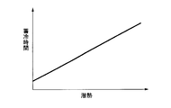
例えば、蓄冷材513の熱伝導率よりも高い熱伝導率を有する材料を、蓄冷材523として用いることで、第2蓄冷機構520の蓄放冷性能を相対的に高めることとしてもよい。図11Aに示されるように、蓄冷材523の熱伝導率が高くなるほど蓄放冷性能も高くなり、その結果として蓄冷時間が短くなる。
蓄冷材523の熱伝導率を高くするには、例えば、蓄冷材513と同一のパラフィンに、カーボンナノチューブを添加すればよい。また、蓄冷材513のパラフィンよりも熱伝導率の高いパラフィンを、蓄冷材523として用いてもよい。本開示を実施するにあたっては、第1蓄冷機構510における蓄冷材513の熱伝導率を0.1W/mKから0.6W/mKの範囲内とし、第2蓄冷機構520における蓄冷材523の熱伝導率を0.6W/mK以上することが望ましい。
蓄冷材513と蓄冷材523との間で互いに異ならせる物性値は、上記のような熱伝導率ではなく他の物性値としてもよい。このような物性値としては、例えば融点や潜熱等が挙げられる。
図11Bに示されるように、蓄冷材523の融点が高くなるほど第2蓄冷機構520の蓄放冷性能も高くなり、その結果として蓄冷時間が短くなる。また、図11Cに示されるように、蓄冷材523の潜熱が小さくなるほど第2蓄冷機構520の蓄放冷性能も高くなり、その結果として蓄冷時間が短くなる。
第2蓄冷機構520の蓄放冷性能を相対的に高めるための構成としては、以上に挙げたものに限定されず、様々な構成を採用し得る。例えば、蓄冷容器521の内壁面に凹凸やフィン等を形成することにより、蓄冷容器521と蓄冷材523との接触面積を、蓄冷容器511と蓄冷材513との接触面積よりも広くしてもよい。このような態様であっても、第2蓄冷機構520の蓄放冷性能を、第1蓄冷機構510の蓄放冷性能に比べて高くすることができる。
(第5実施形態)
図12及び図13を参照しながら、本開示の第5実施形態について説明する。第5実施形態においては、第1蓄冷機構510及び第2蓄冷機構520のそれぞれの形状や配置において第1実施形態と異なっている。他の構成については、第1実施形態と同一である。
図12及び図13を参照しながら、本開示の第5実施形態について説明する。第5実施形態においては、第1蓄冷機構510及び第2蓄冷機構520のそれぞれの形状や配置において第1実施形態と異なっている。他の構成については、第1実施形態と同一である。
本実施形態では、第1蓄冷機構510と第2蓄冷機構520とが、これまでの例のようにx方向に沿って交互に並ぶのではなく、蒸発器10を空気が通過する方向(y方向)に沿って並ぶように配置されている。具体的には、空気が通過する方向における上流側に第2蓄冷機構520が配置されており、下流側に第1蓄冷機構510が配置されている。
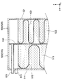
本実施形態では、第1蓄冷機構510の蓄冷容器511と、第2蓄冷機構520の蓄冷容器521とが互いに分離されておらず、全体が一つの容器として構成されている。当該容器の内部のうちy方向に沿った中央となる位置には、仕切り板530が配置されている。容器の内部空間は、仕切り板530によって2つに区切られている。仕切り板よりも-x方向側の部分が第1蓄冷機構510となっており、仕切り板よりもx方向側の部分が第2蓄冷機構520となっている。図12においては、インナーフィン512、522の図示が省略されている。
図13に示されるように、蓄冷容器511のy方向側の側面のうち上端部近傍には、y方向に向けて突出する充填部515が形成されている。充填部515は、蓄冷容器511の内部に蓄冷材513を充填する際における、蓄冷材513の入口となる部分である。
同様に、蓄冷容器521の-y方向側の側面のうち上端部近傍には、-y方向に向けて突出する充填部525が形成されている。充填部525は、蓄冷容器521の内部に蓄冷材523を充填する際における、蓄冷材523の入口となる部分である。
本実施形態では、蒸発器10を冷媒が通過する際の圧力損失が比較的大きくなっており、冷媒の流れに沿った上流側(冷媒入口側)における冷媒温度と、冷媒の流れに沿った下流側(冷媒出口側)における冷媒温度との差が大きくなっている。また、冷媒温度が比較的高い冷媒入口側の部分が風下側(y方向側)となり、冷媒温度が比較的低い冷媒出口側の部分が風上側(-y方向側)となるように、蒸発器10が設置されている。
比較的短期間で蓄冷を行う必要のある第2蓄冷機構520が、冷媒温度が低い風上側(-y方向側)に配置されているので、省エネモード運転における蓄冷がより効率的に行われる。
尚、蒸発器10を冷媒が通過する際の圧力損失が比較的小さいような場合には、冷媒入口側における冷媒温度と、冷媒出口側における冷媒温度との差も小さくなる。このような場合には、空気負荷の低い風下側(y方向側)に、第2蓄冷機構520を配置すればよい。
本実施形態では、一対の第1蓄冷機構510及び第2蓄冷機構520が、空気が通過する方向(y方向)に沿って並べられている。このため、例えば図2のようにx方向に沿ってこれらが並べられている場合比べると、蒸発器10を空気が通過する際に受ける通風抵抗が抑制されている。その結果、蒸発器10の性能を維持しながらも、空気を送り込むために設置されるブロアを小型化することができる。
第1蓄冷機構510と第2蓄冷機構520とをy方向に沿って並べるための具体的な構成としては、図13に示されるような構成のほか、様々な構成を採用し得る。
図14に示される例では、充填部525が、仕切り板530及び蓄冷容器511を貫くように配置された配管として構成されている。充填部525は、-y方向側の端部が仕切り板530に形成された貫通穴に挿通されており、その内部空間と蓄冷容器521の内部空間とが連通されている。また、充填部525のうちy方向側の端部は、充填部515と同様に、蓄冷容器511のy方向側の側面からy方向に向けて突出している。
図15に示される例では、仕切り板530が存在しておらず、蓄冷容器511と蓄冷容器521とがそれぞれ別体の容器として形成されている。また、蓄冷容器511の上端部の位置は、蓄冷容器521の上端部の位置よりも低くなっている。充填部525は、図14の例と同様の配管として構成されているのであるが、その全体が蓄冷容器511の外側(上方側)に配置されている。
図16に示される例では、仕切り板530が存在しておらず、蓄冷容器511の内部空間と蓄冷容器521の内部空間とが分離されていない。図16の点線DLよりもy方向側の部分が第1蓄冷機構510であり、点線DLよりも-y方向側の部分が第2蓄冷機構520なのであるが、内部の蓄冷材(513、523)が双方で共有された構成となっている。この構成においては蓄冷材の入口は1箇所でよいため、充填部525のみが形成されており充填部515は形成されていない。
図17に示される例では、仕切り板530の上端と、蓄冷容器511、521の天板との間が離間している。仕切り板530の上端位置は、充填部515の下端位置よりも下方側となっている。この例では充填部515のみが形成されており、充填部525は形成されていない。蓄冷材513とは異なる材質の蓄冷材523を蓄冷容器521に充填する場合には、注射器などにより、充填部515から蓄冷材523を充填すればよい。
図18に示される例では、図17の例と同様に、仕切り板530の上端と、蓄冷容器511、521の天板との間が離間している。また、仕切り板530の上端から、y方向に向けて伸びる天板531が形成されている。蓄冷容器511の内部空間と、蓄冷容器521の内部空間とは、仕切り板530と天板531とによって完全に分離されている。充填部515は天板531よりも下方側に形成されており、充填部525は天板531よりも上方側に形成されている。
図19に示される例では、図15の例と同様に仕切り板530が存在しておらず、蓄冷容器511と蓄冷容器521とがそれぞれ別体の容器として形成されている。この例では、蓄冷容器511の上端部と、蓄冷容器521の上端部とは同じ高さとなっている。
以上、図13乃至図19を参照しながら説明したように、第1蓄冷機構510と第2蓄冷機構520とをy方向に沿って並べるための具体的な構成としては、図13に示されるような構成のほか、様々な構成を採用し得る。尚、第1蓄冷機構510と第2蓄冷機構520とをy方向に沿って並べるにあたっては、蓄冷機構500全体のy方向に沿った寸法が、チューブ300のy方向に沿った寸法よりも大きくなってもよい。つまり、第1蓄冷機構510又は第2蓄冷機構520のうち少なくとも一方が、チューブ300やコルゲートフィンの端部よりも外方側(-y方向側、又はy方向側)に向かって突出しているような態様であってもよい。
(第6実施形態)
図20を参照しながら、本開示の第6実施形態について説明する。第2実施形態においては、第1蓄冷機構510の構成及び配置についてのみ第1実施形態と異なっており、他の構成については第1実施形態と同一である。
図20を参照しながら、本開示の第6実施形態について説明する。第2実施形態においては、第1蓄冷機構510の構成及び配置についてのみ第1実施形態と異なっており、他の構成については第1実施形態と同一である。
本実施形態における第1蓄冷機構510は、これまでの例とは異なり、蒸発器10のうち複数のチューブ300が配置された部分、すなわちコア部には配置されていない。第1蓄冷機構510は、コア部よりも外側(-z方向側)となる位置において、下部タンク200に隣接する位置に配置されている。一方、本実施形態における第2蓄冷機構520は、これまでの例と同様にコア部に配置されている(図20では不図示)。
本実施形態における下部タンク200は、互いに略同一形状の二つのタンク(第1下部タンク201、第2下部タンク202)が、y方向に沿って並ぶように配置された構成となっている。それぞれのタンクは、その長手方向をx軸に沿わせた状態で配置されている。このため、第1下部タンク201と第2下部タンク202との間(且つ下方側)には、x軸に沿った凹部210が形成されている。第1蓄冷機構510は、この凹部210内に収納されている。
尚、第1蓄冷機構510(蓄冷容器511)の外形は、凹部210に収納可能な形状となっており、第1実施形態等における第1蓄冷機構510の外形とは異なっている。しかしながら、その蓄放冷性能が第2蓄冷機構520の蓄放冷性能よりも低い点については、第1実施形態などと同じである。
このような構成においては、蓄冷機構500の全てがコア部に配置されているのではなく、その一部(第1蓄冷機構510)がコア部の外側に配置されている。蒸発器10を空気が通過する際に受ける通風抵抗が抑制されるので、蒸発器10の性能を維持しながらも、空気を送り込むために設置されるブロアを小型化することができる。
第2蓄冷機構520は、これまでの例と同様にコア部に配置されている。コア部は、冷媒の流れによって第2蓄冷機構520の冷却(熱伝達)が効率的に行われる部分であるから、省エネモード運転における蓄冷が効率的に行われる。
また、第1蓄冷機構510はコア部の外側に配置されるのであるが、下部タンク200によって冷却される。このため、アイドルストップの状態に移行した後に吹き出し温度の上昇を抑制するという機能は、これまでと同様に発揮される。
(第7実施形態)
図21を参照しながら、本開示の第7実施形態について説明する。第7実施形態においては、第1蓄冷機構510及び第2蓄冷機構520のそれぞれの形状や配置において第1実施形態と異なっている。他の構成については、第1実施形態と同一である。
図21を参照しながら、本開示の第7実施形態について説明する。第7実施形態においては、第1蓄冷機構510及び第2蓄冷機構520のそれぞれの形状や配置において第1実施形態と異なっている。他の構成については、第1実施形態と同一である。
本実施形態では、互いに隣り合う2本のチューブ300に挟まれた空間内において、第1蓄冷機構510と第2蓄冷機構520とが上下方向(z方向)に沿って並ぶように配置されている。具体的には、上方側に第1蓄冷機構510が配置されており、下方側に第2蓄冷機構520が配置されている。
蓄冷機構500がこのように配置された場合の効果について、図21及び図22を参照しながら説明する。図22には、アイドルストップの状態に移行した時刻t100以降における、各部の温度変化が示されている。図22の線G20は、吹き出し温度の時間変化を示すグラフである。図22の線G21は、第1蓄冷機構510における蓄冷材513の温度の時間変化を示すグラフである。図22の線G22は、第2蓄冷機構520における蓄冷材523の温度の時間変化を示すグラフである。
蓄冷材513の温度(線G21)は、時刻t100以降において次第に上昇して行く。第1蓄冷機構510の蓄放冷性能は低いので、周囲のチューブ300等を冷却する性能も低い。このため、時刻t100の直後においては、周囲の温度上昇に伴って、比較的大きな速度で蓄冷材513の温度が上昇して行く。
ただし、第1蓄冷機構510の蓄放冷性能が低いということは、内部の蓄冷材513の全てが融解するまでに要する時間は比較的長いということである。このため、蓄冷材513は長時間に亘って周囲を冷却し続ける。
蓄冷材523の温度(線G22)も、時刻t100以降において次第に上昇して行く。ただし、第2蓄冷機構520の蓄放冷性能は高いので、周囲のチューブ300等を冷却する性能も高い。このため、時刻t100の直後においては、周囲の温度が上昇しても蓄冷材523は低温に保たれている。
ただし、第2蓄冷機構520の蓄放冷性能が高いということは、内部の蓄冷材523の全てが融解するまでに要する時間は比較的短いということである。蓄冷材513は短時間のうちにその温度を上昇させるので、周囲を冷却し続ける時間は短い。
蓄冷材513及び蓄冷材523のそれぞれの温度は上記のように変化する。このため、アイドルストップに移行してからの期間が比較的短い時刻t200においては、蓄冷材513の温度よりも蓄冷材523の温度の方が低い。また、アイドルストップに移行してからの期間が比較的長い時刻t300においては、蓄冷材513の温度よりも蓄冷材523の温度の方が高い。
ところで、アイドルストップの状態となり、コンプレッサが停止すると、チューブ300内では冷媒が液相から気相へと変化していく。このとき、コア部の下方側で気相となった冷媒はチューブ300を上方側に向かって移動するのであるが、上方側の部分において冷却されると、再び液相となって下方側に移動する(図21の矢印AR1)。その結果、液相となった冷媒が長期間に亘り存在し続けるので、吹き出し温度の上昇が抑制される。
例えば、図21のように第1蓄冷機構510の方が上方側に配置されている場合には、アイドルストップに移行してから長期間が経過したとき(図22の時刻t30)に、上方側の方が低温となり、上記のように吹き出し温度が抑制される。すなわち、蓄冷材523の温度(G22)は上昇しているのであるが、吹き出し温度はそれよりも低い状態に維持される。
一方、図21の例とは逆に、第2蓄冷機構520の方が上方側に配置されている場合には、アイドルストップに移行してから短期間が経過したとき(図22の時刻t20)にのみ、上方側の方が低温となり、上記のように吹き出し温度が抑制される。すなわち、蓄冷材513の温度(G21)は上昇しているのであるが、吹き出し温度はそれよりも低い状態に維持される。
アイドルストップに移行した後、吹き出し温度がある程度上昇することは許容しながらも、空気の冷却を長期間に亘って行いたい場合(時刻t30のタイミングで効果を発揮させたい場合)には、図21のように第1蓄冷機構510を上方側に配置すればよい。一方、アイドルストップに移行した後、空気の冷却が短期間で終了することは許容しながらも、当該期間における空気の温度上昇を極力抑えたい場合(時刻t20のタイミングで効果を発揮させたい場合)には、図21とは逆に第2蓄冷機構520を上方側に配置すればよい。
(第8実施形態)
本開示の第8実施形態について説明する。図示は省略するが、本実施形態においては、蓄冷容器511の形状と蓄冷容器521の形状は互いに同一であり、それぞれが図1に示される蓄冷容器511の形状となっている。また、インナーフィン512の形状とインナーフィン522の形状は互いに同一であり、図1に示されるインナーフィン512の形状となっている。つまり、本実施形態においては、第1蓄冷機構510及び第2蓄冷機構520の構造は互いに同一となっている。ただし、本実施形態では、第1蓄冷機構510の蓄冷材513と、第2蓄冷機構520の蓄冷材523とが互いに異なっている。その他の構成においては、図1等に示される第1実施形態の構成と同じである。
本開示の第8実施形態について説明する。図示は省略するが、本実施形態においては、蓄冷容器511の形状と蓄冷容器521の形状は互いに同一であり、それぞれが図1に示される蓄冷容器511の形状となっている。また、インナーフィン512の形状とインナーフィン522の形状は互いに同一であり、図1に示されるインナーフィン512の形状となっている。つまり、本実施形態においては、第1蓄冷機構510及び第2蓄冷機構520の構造は互いに同一となっている。ただし、本実施形態では、第1蓄冷機構510の蓄冷材513と、第2蓄冷機構520の蓄冷材523とが互いに異なっている。その他の構成においては、図1等に示される第1実施形態の構成と同じである。
蓄冷材513としては、炭素数が15のパラフィン(C15)が用いられており、その融点は9℃となっている。また、蓄冷材523としては、炭素数が16のパラフィン(C16)が用いられており、その融点は17℃となっている。このように、第2蓄冷機構520における蓄冷材523の融点が、第1蓄冷機構510における蓄冷材513の融点よりも高くなっている。
このように、蓄冷材の融点を異ならせることの効果について、図23A、23Bを参照しながら説明する。図23Aに示されるのは、本実施形態に係る第1蓄冷機構510がチューブ300内の冷媒で冷却される際における、蓄冷材513の温度変化である。図23Aでは、蓄冷材513の融点が融点T100として示されている。また、図23Aでは、時刻t0の冷却開始時における蓄冷材513の温度が初期温度T0として示されている。更に、チューブ300内の冷媒の温度が冷媒温度T200として示されている。冷媒温度T200は、初期温度T0及び融点T100のいずれよりも低い温度である。また、初期温度T0は、融点T100よりも高い温度である。
図23Aに示されるように、時刻t0以降においては蓄冷材513の温度が次第に低くなって行き、時刻t100において融点T100となる。時刻t100からは蓄冷材513が凝固し始めて、時刻t200において蓄冷材513の全体が凝固した状態となる。時刻t100から時刻t200までの期間TM1においては蓄冷材513の温度は一定(融点T100)である。時刻t200以降は、再び蓄冷材513の温度が低下して行く。
図23Bに示されるのは、本実施形態に係る第2蓄冷機構520がチューブ300内の冷媒で冷却される際における、蓄冷材523の温度変化である。図23Bにおいては、蓄冷材523の融点が融点T110として示されている。既に述べたように、融点T110は融点T100よりも高い。
図23Bでは、時刻t0の冷却開始時における蓄冷材523の温度が初期温度T0として示されている。また、図23Bでは、チューブ300内の冷媒の温度が冷媒温度T200として示されている。初期温度T0及び冷媒温度T200は、図23Aに示される初期温度T0及び冷媒温度T200とそれぞれ同じ温度である。また、融点T110は、初期温度T0も低い温度である。
図23Bの例においても、時刻t0以降においては蓄冷材523の温度が次第に低くなって行き、時刻t110において融点T110となる。時刻t110からは蓄冷材523が凝固し始めて、時刻t120において蓄冷材523の全体が凝固した状態となる。時刻t110から時刻t120までの期間TM2においては蓄冷材523の温度は一定(融点T110)である。時刻t120以降は、再び蓄冷材523の温度が低下して行く。
ここで、蓄冷材513が凝固しているときにおける、蓄冷材513と冷媒との温度差を温度差ΔT1とする。また、蓄冷材523が凝固しているときにおける、蓄冷材523と冷媒との温度差を温度差ΔT2とする。この場合、蓄冷材523の融点T110が、蓄冷材513の融点T100よりも高いので、温度差ΔT2は温度差ΔT1よりも大きい。このため、期間TM2において蓄冷材523から熱が奪われて行く速度は、期間TM1において蓄冷材513から熱が奪われて行く速度よりも大きくなっている。その結果、期間TM2の長さは、期間TM1の長さよりも短くなっている。
本実施形態では、蓄冷材523として融点の高い材料が用いられたことで、蓄冷材523の方が蓄冷材513よりも早く凝固する。つまり、第2蓄冷機構520の蓄放冷性能が、第1蓄冷機構510の蓄放冷性能よりも高くなっている。その結果、第1実施形態と同様の効果を奏する。尚、蓄冷材513及び蓄冷材523のそれぞれの具体的な材料としては、上記とは異なる材料とが用いられてもよい。
(第9実施形態)
図24A、24Bを参照しながら、本開示の第9実施形態について説明する。図示は省略するが、本実施形態においては、蓄冷容器511の形状と蓄冷容器521の形状は互いに同一であり、それぞれが図1に示される蓄冷容器511の形状となっている。また、インナーフィン512の形状とインナーフィン522の形状は互いに同一であり、図1に示されるインナーフィン512の形状となっている。つまり、本実施形態においては、第1蓄冷機構510及び第2蓄冷機構520の構造は互いに同一となっている。ただし、本実施形態では、一部におけるチューブ300の形状が、第1実施形態の場合とは異なっている。その他の構成においては、図1等に示される第1実施形態の構成と同じである。
図24A、24Bを参照しながら、本開示の第9実施形態について説明する。図示は省略するが、本実施形態においては、蓄冷容器511の形状と蓄冷容器521の形状は互いに同一であり、それぞれが図1に示される蓄冷容器511の形状となっている。また、インナーフィン512の形状とインナーフィン522の形状は互いに同一であり、図1に示されるインナーフィン512の形状となっている。つまり、本実施形態においては、第1蓄冷機構510及び第2蓄冷機構520の構造は互いに同一となっている。ただし、本実施形態では、一部におけるチューブ300の形状が、第1実施形態の場合とは異なっている。その他の構成においては、図1等に示される第1実施形態の構成と同じである。
以下では、複数のチューブ300のうち第1蓄冷機構510に接触しているものを「チューブ300A」と表記する。また、複数のチューブ300のうち第2蓄冷機構520に接触しているものを「チューブ300B」と表記する。図24Aに示されるのは、チューブ300Aを冷媒の流れ方向に沿って垂直な面で切断した場合における断面図である。図24Bに示されるのは、チューブ300Bを冷媒の流れ方向に沿って垂直な面で切断した場合における断面図である。チューブ300A及びチューブ300Bは、いずれもアルミニウムの押し出し成形によって形成されている。
チューブ300Aに形成された流路301(以下、「流路301A」と表記する)は、チューブ300Aにおいて複数個形成されており、それぞれの断面形状が矩形となっている。それぞれの流路301Aは、一定のピッチで一列に並んでいる。
同様に、チューブ300Bに形成された流路301(以下、「流路301B」と表記する)は、チューブ300Bにおいて複数個形成されており、それぞれの断面形状が矩形となっている。それぞれの流路301Bは、一定のピッチで一列に並んでいる。ただし、それぞれの流路301Bの流路断面積は、それぞれの流路301Aの流路断面積よりも小さくなっている。また、流路301Bの配置ピッチは、流路301Aの配置ピッチよりも狭くなっている。チューブ300Aとチューブ300Bとを比較すると、流路301Bと冷媒との接触面積が、流路301Aと冷媒との接触面積よりも大きくなっている。その結果、第2蓄冷機構520の蓄放熱性能は、第1蓄冷機構510の蓄放熱性能よりも相対的に高くなっている。このような態様であっても、第1実施形態と同様の効果を奏する。
尚、「流路301Bと冷媒との接触面積」とは、流路301Bの内面の面積を、1本のチューブ300Bに形成された全ての流路301Bについて合計して得られる面積のことである。「流路301Aと冷媒との接触面積」についても同様に定義される。
以上に説明した第9実施形態の変形例について、図25A、25Bを参照しながら説明する。この変形例においても、蓄冷容器511の形状と蓄冷容器521の形状は互いに同一であり、それぞれが図1に示される蓄冷容器511の形状となっている。また、インナーフィン512の形状とインナーフィン522の形状は互いに同一であり、図1に示されるインナーフィン512の形状となっている。
この変形例では、チューブ300Aに替えて、図25Aに示されるチューブ300Cが用いられる。また、チューブ300Bに替えて、図25Bに示されるチューブ300Dが用いられる。図25Aに示されるのは、チューブ300Cを冷媒の流れ方向に沿って垂直な面で切断した場合における断面図である。図25Bに示されるのは、チューブ300Dを冷媒の流れ方向に沿って垂直な面で切断した場合における断面図である。
チューブ300Cは、容器310Cとフィン311Cとを有している。容器310Cは、金属板を折り曲げて端部を加締めることによって形成された容器であって、その断面が扁平形状となっている。
フィン311Cは、コルゲートフィン400と同様に、金属板(アルミニウム)を波状に折り曲げることにより形成されたものである。波状であるフィン311Cの頂部は、容器310Cの内壁面に対して当接しており、且つろう接されている。その結果、容器310Cの内部空間は、フィン311Cによって複数の空間に区画されている。それぞれの空間が、冷媒の流れる流路301Cとなっている。
チューブ300Dも、上記と同様の構成となっている。チューブ300Dは、容器310Dとフィン311Dとを有している。容器310Dは、金属板を折り曲げて端部を加締めることによって形成された容器であって、その断面が扁平形状となっている。
フィン311Dは、コルゲートフィン400と同様に、金属板(アルミニウム)を波状に折り曲げることにより形成されたものである。波状であるフィン311Dの頂部は、容器310Dの内壁面に対して当接しており、且つろう接されている。その結果、容器310Dの内部空間は、フィン311Dによって複数の空間に区画されている。それぞれの空間が、冷媒の流れる流路301Dとなっている。
図25A、25Bに示されるように、フィン311Dのピッチ、すなわちフィン311Dにおいて隣り合う頂部同士の間隔は、フィン311Cのピッチ、すなわちフィン311Cにおいて隣り合う頂部同士の間隔よりも狭くなっている。その結果、この変形例においても、流路301Dと冷媒との接触面積が、流路301Cと冷媒との接触面積よりも大きくなっている。その結果、第2蓄冷機構520の蓄放熱性能が、第1蓄冷機構510の蓄放熱性能よりも相対的に高くなっている。このような態様であっても、第1実施形態と同様の効果を奏する。
以上、具体例を参照しつつ本開示の実施の形態について説明した。しかし、本開示はこれらの具体例に限定されるものではない。すなわち、これら具体例に、当業者が適宜設計変更を加えたものも、本開示の特徴を備えている限り、本開示の範囲に包含される。例えば、前述した各具体例が備える各要素およびその配置、材料、条件、形状、サイズなどは、例示したものに限定されるわけではなく適宜変更することができる。また、前述した各実施の形態が備える各要素は、技術的に可能な限りにおいて組み合わせることができ、これらを組み合わせたものも本開示の特徴を含む限り本開示の範囲に包含される。
本開示は、実施例に準拠して記述されたが、本開示は当該実施例や構造に限定されるものではないと理解される。本開示は、様々な変形例や均等範囲内の変形をも包含する。加えて、様々な組み合わせや形態、さらには、それらに一要素のみ、それ以上、あるいはそれ以下、を含む他の組み合わせや形態をも、本開示の範疇や思想範囲に入るものである。
Claims (22)
- 内部を通る冷媒との熱交換により空気を冷却する蒸発器(10)であって、
蓄冷容器(511、521)の内部に収納された蓄冷材(513、523)の温度を前記冷媒との熱交換により低下させる蓄冷機構(500)、を複数備えており、
前記蓄冷機構の1つである第1蓄冷機構(510)と、
前記蓄冷機構の1つであって、前記第1蓄冷機構よりも蓄放熱性能が高い第2蓄冷機構(520)と、を備えた蒸発器。 - 前記第1蓄冷機構及び前記第2蓄冷機構は、いずれも、前記冷媒が内部を通るチューブ(300)に対し接触した状態で配置されており、
前記第2蓄冷機構と前記チューブとの接触面積は、前記第1蓄冷機構と前記チューブとの接触面積よりも広くなっており、これにより前記第2蓄冷機構の蓄放熱性能が相対的に高められている、請求項1に記載の蒸発器。 - 前記第2蓄冷機構における前記蓄冷容器と前記蓄冷材との接触面積は、前記第1蓄冷機構における前記蓄冷容器と前記蓄冷材との接触面積よりも広くなっている、請求項1に記載の蒸発器。
- 前記第1蓄冷機構及び前記第2蓄冷機構は、いずれも、前記蓄冷材への伝熱を促進するための伝熱促進物(512、522)が前記蓄冷容器の内部に収納された構成となっている、請求項1に記載の蒸発器。
- 前記第2蓄冷機構における前記蓄冷容器と前記伝熱促進物との接触面積は、前記第1蓄冷機構における前記蓄冷容器と前記伝熱促進物との接触面積よりも広くなっている、請求項4に記載の蒸発器。
- 前記第2蓄冷機構における前記伝熱促進物と前記蓄冷材との接触面積は、前記第1蓄冷機構における前記伝熱促進物と前記蓄冷材との接触面積よりも広くなっている、請求項4に記載の蒸発器。
- 前記蓄冷材のうち前記伝熱促進物の表面から最も離れている点と、前記伝熱促進物の表面との間の距離、を相変化距離と定義したときにおいて、
前記第2蓄冷機構における前記相変化距離は、前記第1蓄冷機構における前記相変化距離よりも小さくなっている、請求項4に記載の蒸発器。 - 前記伝熱促進物は、金属板を波状に折り曲げることにより形成されたインナーフィンであって、
前記第1蓄冷機構における前記インナーフィンと、前記第2蓄冷機構における前記インナーフィンとは、その形状又は材質において互いに異なっている、請求項4に記載の蒸発器。 - 前記第2蓄冷機構における前記インナーフィンのピッチは、前記第1蓄冷機構における前記インナーフィンのピッチよりも小さい、請求項8に記載の蒸発器。
- 前記第2蓄冷機構における前記インナーフィンの板厚は、前記第1蓄冷機構における前記インナーフィンの板厚よりも大きい、請求項8に記載の蒸発器。
- 前記第2蓄冷機構における前記インナーフィンの熱伝導率は、前記第1蓄冷機構における前記インナーフィンの熱伝導率よりも大きい、請求項8に記載の蒸発器。
- 前記第2蓄冷機構における前記蓄冷材の熱伝導率は、前記第1蓄冷機構における前記蓄冷材の熱伝導率よりも大きくなっている、請求項1に記載の蒸発器。
- 前記第1蓄冷機構と前記第2蓄冷機構とが、上下方向に沿って並ぶように配置されている、請求項1に記載の蒸発器。
- 前記第1蓄冷機構と前記第2蓄冷機構とが、空気が通過する方向に沿って並ぶように配置されている、請求項1に記載の蒸発器。
- 前記冷媒が内部を通る複数のチューブと、
前記チューブに対する前記冷媒の供給、または前記チューブを通った前記冷媒の受け入れのうち少なくとも一方を行うタンク(200)と、を備えており、
前記第2蓄冷機構は、複数の前記チューブが配置された部分であるコア部に配置されており、
前記第1蓄冷機構は、前記コア部とは異なる位置であり且つ前記タンクに隣接する位置に配置されている、請求項1に記載の蒸発器。 - 前記第2蓄冷機構における前記蓄冷材の融点は、前記第1蓄冷機構における前記蓄冷材の融点よりも高くなっている、請求項1に記載の蒸発器。
- 前記冷媒の通る流路が内部に形成されたチューブを複数備え、
前記第1蓄冷機構及び前記第2蓄冷機構は、いずれも、前記チューブに対し接触した状態で配置されており、
前記チューブのうち前記第2蓄冷機構に接触しているもの、に形成された前記流路と前記蓄冷材との接触面積は、
前記チューブのうち前記第1蓄冷機構に接触しているもの、に形成された前記流路と前記蓄冷材との接触面積よりも大きくなっており、これにより前記第2蓄冷機構の蓄放熱性能が相対的に高められている、請求項1に記載の蒸発器。 - 内部を通る冷媒との熱交換により空気を冷却する蒸発器であって、
前記冷媒が内部を通る複数のチューブと、
互いに隣り合う前記チューブの間に保持されており、その温度を前記冷媒との熱交換により低下させる複数の蓄冷機構と、を備えており、
前記蓄冷機構の1つである第1蓄冷機構と、
前記蓄冷機構の1つであって、前記第1蓄冷機構よりも蓄放熱性能が高い第2蓄冷機構と、を備えた蒸発器。 - 前記伝熱促進物は、波形状を有する金属板を有するインナーフィンであって、
前記第1蓄冷機構における前記インナーフィンと、前記第2蓄冷機構における前記インナーフィンとは、その形状又は材質において互いに異なっている、請求項4に記載の蒸発器。 - 前記冷媒の通る流路が内部に形成された複数のチューブを備え、
前記第1蓄冷機構及び前記第2蓄冷機構は、いずれも、前記チューブに対し接触した状態で配置されており、
前記チューブのうち前記第2蓄冷機構に接触しているもの、に形成された前記流路と前記冷媒との接触面積は、
前記チューブのうち前記第1蓄冷機構に接触しているもの、に形成された前記流路と前記冷媒との接触面積よりも大きくなっており、これにより前記第2蓄冷機構の蓄放熱性能が相対的に高められている、請求項1に記載の蒸発器。 - 内部を通る冷媒との熱交換により空気を冷却する蒸発器(10)であって、
蓄冷容器(511、521)の内部に収納された蓄冷材(513、523)の温度を前記冷媒との熱交換により低下させる複数の蓄冷機構(500)、を備えており、
前記複数の蓄冷機構は、第1蓄冷機構(510)と、前記第1蓄冷機構よりも蓄放熱性能が高い第2蓄冷機構(520)と、を備える、蒸発器。 - 内部を通る冷媒との熱交換により空気を冷却する蒸発器であって、
前記冷媒が内部を通る複数のチューブと、
互いに隣り合う前記チューブの間に保持されており、その温度を前記冷媒との熱交換により低下させる複数の蓄冷機構と、を備えており、
前記複数の蓄冷機構は、第1蓄冷機構と、前記第1蓄冷機構よりも蓄放熱性能が高い第2蓄冷機構と、を備える、蒸発器。
Priority Applications (3)
| Application Number | Priority Date | Filing Date | Title |
|---|---|---|---|
| CN201680024276.0A CN107532861B (zh) | 2015-04-30 | 2016-04-19 | 蒸发器 |
| DE112016001957.2T DE112016001957T5 (de) | 2015-04-30 | 2016-04-19 | Verdampfer |
| US15/569,838 US10677537B2 (en) | 2015-04-30 | 2016-04-19 | Evaporator |
Applications Claiming Priority (4)
| Application Number | Priority Date | Filing Date | Title |
|---|---|---|---|
| JP2015-092589 | 2015-04-30 | ||
| JP2015092589 | 2015-04-30 | ||
| JP2016079306A JP6623912B2 (ja) | 2015-04-30 | 2016-04-12 | 蒸発器 |
| JP2016-079306 | 2016-04-12 |
Publications (1)
| Publication Number | Publication Date |
|---|---|
| WO2016174852A1 true WO2016174852A1 (ja) | 2016-11-03 |
Family
ID=57199115
Family Applications (1)
| Application Number | Title | Priority Date | Filing Date |
|---|---|---|---|
| PCT/JP2016/002097 Ceased WO2016174852A1 (ja) | 2015-04-30 | 2016-04-19 | 蒸発器 |
Country Status (1)
| Country | Link |
|---|---|
| WO (1) | WO2016174852A1 (ja) |
Cited By (1)
| Publication number | Priority date | Publication date | Assignee | Title |
|---|---|---|---|---|
| WO2019232503A1 (en) * | 2018-06-01 | 2019-12-05 | University Of Southern California | Diverse antigen binding domains, novel platforms and other enhancements for cellular therapy |
Citations (6)
| Publication number | Priority date | Publication date | Assignee | Title |
|---|---|---|---|---|
| JP2008020177A (ja) * | 2006-06-15 | 2008-01-31 | Matsushita Electric Ind Co Ltd | 蓄熱システム |
| JP2010043779A (ja) * | 2008-08-12 | 2010-02-25 | Mitsubishi Electric Corp | 蓄冷パネルおよびこれを備えた冷凍・冷蔵装置 |
| JP2011012947A (ja) * | 2009-06-05 | 2011-01-20 | Denso Corp | 蓄冷熱交換器 |
| JP2013018299A (ja) * | 2011-07-07 | 2013-01-31 | Keihin Thermal Technology Corp | 車両用空調装置のクーリングユニット |
| WO2013042273A1 (ja) * | 2011-09-21 | 2013-03-28 | ナサコア株式会社 | 空気調和装置 |
| WO2013186983A1 (ja) * | 2012-06-14 | 2013-12-19 | 株式会社デンソー | 蓄冷熱交換器 |
-
2016
- 2016-04-19 WO PCT/JP2016/002097 patent/WO2016174852A1/ja not_active Ceased
Patent Citations (6)
| Publication number | Priority date | Publication date | Assignee | Title |
|---|---|---|---|---|
| JP2008020177A (ja) * | 2006-06-15 | 2008-01-31 | Matsushita Electric Ind Co Ltd | 蓄熱システム |
| JP2010043779A (ja) * | 2008-08-12 | 2010-02-25 | Mitsubishi Electric Corp | 蓄冷パネルおよびこれを備えた冷凍・冷蔵装置 |
| JP2011012947A (ja) * | 2009-06-05 | 2011-01-20 | Denso Corp | 蓄冷熱交換器 |
| JP2013018299A (ja) * | 2011-07-07 | 2013-01-31 | Keihin Thermal Technology Corp | 車両用空調装置のクーリングユニット |
| WO2013042273A1 (ja) * | 2011-09-21 | 2013-03-28 | ナサコア株式会社 | 空気調和装置 |
| WO2013186983A1 (ja) * | 2012-06-14 | 2013-12-19 | 株式会社デンソー | 蓄冷熱交換器 |
Cited By (3)
| Publication number | Priority date | Publication date | Assignee | Title |
|---|---|---|---|---|
| WO2019232503A1 (en) * | 2018-06-01 | 2019-12-05 | University Of Southern California | Diverse antigen binding domains, novel platforms and other enhancements for cellular therapy |
| IL279100B1 (en) * | 2018-06-01 | 2025-02-01 | Univ Southern California | Diverse antigen binding sites, new platforms and other improvements for cell therapy |
| IL279100B2 (en) * | 2018-06-01 | 2025-06-01 | Univ Southern California | Diverse antigen binding domains, novel platforms and other enhancements for cellular therapy |
Similar Documents
| Publication | Publication Date | Title |
|---|---|---|
| JP6623912B2 (ja) | 蒸発器 | |
| JP5868088B2 (ja) | 車両用空調装置のクーリングユニット | |
| WO2013186983A1 (ja) | 蓄冷熱交換器 | |
| JP5910415B2 (ja) | 蓄冷熱交換器 | |
| US11059345B2 (en) | Storage evaporator having phase change material for use in vehicle air conditioning system | |
| EP3147617B1 (en) | Heat exchanger | |
| JP5274175B2 (ja) | 蓄冷熱交換器 | |
| JP6281394B2 (ja) | 蓄冷熱交換器 | |
| US10401062B2 (en) | Cold storage heat exchanger | |
| US10696128B2 (en) | Cold storage heat exchanger | |
| JP2010261658A (ja) | 蓄冷機能付きエバポレータ | |
| JP6658875B2 (ja) | 蓄冷蒸発器およびそれを備える車両用冷凍サイクル装置 | |
| JP2010203748A (ja) | 蓄冷機能付きエバポレータ | |
| WO2016174852A1 (ja) | 蒸発器 | |
| JP2010139201A (ja) | 蓄冷器およびこれを用いた車両用空調装置 | |
| JP2010243066A (ja) | 蓄冷熱交換器 | |
| JP6206209B2 (ja) | 蓄冷熱交換器 | |
| JP6699507B2 (ja) | 空調装置 | |
| CN105202819A (zh) | 带蓄冷功能的蒸发器 | |
| JP2019099137A (ja) | 熱交換器 | |
| JP6720927B2 (ja) | 熱交換器 | |
| WO2019107001A1 (ja) | 熱交換器 | |
| JP2013200073A (ja) | 蓄冷機能付きエバポレータ | |
| JP2021101137A (ja) | 蓄冷用熱交換器 | |
| JP2019182085A (ja) | 蒸発器 |
Legal Events
| Date | Code | Title | Description |
|---|---|---|---|
| 121 | Ep: the epo has been informed by wipo that ep was designated in this application |
Ref document number: 16786131 Country of ref document: EP Kind code of ref document: A1 |
|
| WWE | Wipo information: entry into national phase |
Ref document number: 15569838 Country of ref document: US |
|
| WWE | Wipo information: entry into national phase |
Ref document number: 112016001957 Country of ref document: DE |
|
| 122 | Ep: pct application non-entry in european phase |
Ref document number: 16786131 Country of ref document: EP Kind code of ref document: A1 |