US10696128B2 - Cold storage heat exchanger - Google Patents
Cold storage heat exchanger Download PDFInfo
- Publication number
- US10696128B2 US10696128B2 US15/765,101 US201615765101A US10696128B2 US 10696128 B2 US10696128 B2 US 10696128B2 US 201615765101 A US201615765101 A US 201615765101A US 10696128 B2 US10696128 B2 US 10696128B2
- Authority
- US
- United States
- Prior art keywords
- cold storage
- refrigerant
- storage material
- material container
- area
- Prior art date
- Legal status (The legal status is an assumption and is not a legal conclusion. Google has not performed a legal analysis and makes no representation as to the accuracy of the status listed.)
- Active
Links
- 238000003860 storage Methods 0.000 title claims abstract description 101
- 239000003507 refrigerant Substances 0.000 claims abstract description 807
- 239000011232 storage material Substances 0.000 claims abstract description 488
- 238000012546 transfer Methods 0.000 claims abstract description 102
- 238000005304 joining Methods 0.000 claims description 48
- 238000002844 melting Methods 0.000 claims description 43
- 238000011144 upstream manufacturing Methods 0.000 claims description 30
- 238000005192 partition Methods 0.000 claims description 17
- 230000008018 melting Effects 0.000 claims description 15
- 238000004891 communication Methods 0.000 claims description 5
- 230000008020 evaporation Effects 0.000 claims description 5
- 238000001704 evaporation Methods 0.000 claims description 5
- 230000000694 effects Effects 0.000 description 44
- 230000004048 modification Effects 0.000 description 15
- 238000012986 modification Methods 0.000 description 15
- 239000000463 material Substances 0.000 description 14
- 230000008859 change Effects 0.000 description 12
- 238000010586 diagram Methods 0.000 description 11
- 230000005484 gravity Effects 0.000 description 8
- 238000001816 cooling Methods 0.000 description 7
- 238000005219 brazing Methods 0.000 description 6
- 230000007704 transition Effects 0.000 description 6
- 229910052782 aluminium Inorganic materials 0.000 description 4
- XAGFODPZIPBFFR-UHFFFAOYSA-N aluminium Chemical compound [Al] XAGFODPZIPBFFR-UHFFFAOYSA-N 0.000 description 4
- 239000003638 chemical reducing agent Substances 0.000 description 4
- 238000009826 distribution Methods 0.000 description 4
- 229910052751 metal Inorganic materials 0.000 description 4
- 239000002184 metal Substances 0.000 description 4
- 238000005338 heat storage Methods 0.000 description 3
- 239000007788 liquid Substances 0.000 description 3
- 238000002485 combustion reaction Methods 0.000 description 2
- 230000000052 comparative effect Effects 0.000 description 2
- 230000007423 decrease Effects 0.000 description 2
- 230000008014 freezing Effects 0.000 description 2
- 238000007710 freezing Methods 0.000 description 2
- 238000000034 method Methods 0.000 description 2
- 229920006395 saturated elastomer Polymers 0.000 description 2
- 238000000638 solvent extraction Methods 0.000 description 2
- 230000002123 temporal effect Effects 0.000 description 2
- 240000006829 Ficus sundaica Species 0.000 description 1
- 239000000853 adhesive Substances 0.000 description 1
- 230000001070 adhesive effect Effects 0.000 description 1
- 238000005452 bending Methods 0.000 description 1
- 230000008901 benefit Effects 0.000 description 1
- 230000015572 biosynthetic process Effects 0.000 description 1
- 238000005520 cutting process Methods 0.000 description 1
- 238000013461 design Methods 0.000 description 1
- 238000007599 discharging Methods 0.000 description 1
- 238000001125 extrusion Methods 0.000 description 1
- 238000007667 floating Methods 0.000 description 1
- 239000011888 foil Substances 0.000 description 1
- 239000000446 fuel Substances 0.000 description 1
- 230000007246 mechanism Effects 0.000 description 1
- 239000011347 resin Substances 0.000 description 1
- 229920005989 resin Polymers 0.000 description 1
Images


Classifications
-
- B—PERFORMING OPERATIONS; TRANSPORTING
- B60—VEHICLES IN GENERAL
- B60H—ARRANGEMENTS OF HEATING, COOLING, VENTILATING OR OTHER AIR-TREATING DEVICES SPECIALLY ADAPTED FOR PASSENGER OR GOODS SPACES OF VEHICLES
- B60H1/00—Heating, cooling or ventilating [HVAC] devices
- B60H1/32—Cooling devices
- B60H1/3204—Cooling devices using compression
- B60H1/3227—Cooling devices using compression characterised by the arrangement or the type of heat exchanger, e.g. condenser, evaporator
-
- B—PERFORMING OPERATIONS; TRANSPORTING
- B60—VEHICLES IN GENERAL
- B60H—ARRANGEMENTS OF HEATING, COOLING, VENTILATING OR OTHER AIR-TREATING DEVICES SPECIALLY ADAPTED FOR PASSENGER OR GOODS SPACES OF VEHICLES
- B60H1/00—Heating, cooling or ventilating [HVAC] devices
- B60H1/00321—Heat exchangers for air-conditioning devices
- B60H1/00335—Heat exchangers for air-conditioning devices of the gas-air type
-
- B—PERFORMING OPERATIONS; TRANSPORTING
- B60—VEHICLES IN GENERAL
- B60H—ARRANGEMENTS OF HEATING, COOLING, VENTILATING OR OTHER AIR-TREATING DEVICES SPECIALLY ADAPTED FOR PASSENGER OR GOODS SPACES OF VEHICLES
- B60H1/00—Heating, cooling or ventilating [HVAC] devices
- B60H1/00492—Heating, cooling or ventilating [HVAC] devices comprising regenerative heating or cooling means, e.g. heat accumulators
- B60H1/005—Regenerative cooling means, e.g. cold accumulators
-
- Y—GENERAL TAGGING OF NEW TECHNOLOGICAL DEVELOPMENTS; GENERAL TAGGING OF CROSS-SECTIONAL TECHNOLOGIES SPANNING OVER SEVERAL SECTIONS OF THE IPC; TECHNICAL SUBJECTS COVERED BY FORMER USPC CROSS-REFERENCE ART COLLECTIONS [XRACs] AND DIGESTS
- Y02—TECHNOLOGIES OR APPLICATIONS FOR MITIGATION OR ADAPTATION AGAINST CLIMATE CHANGE
- Y02E—REDUCTION OF GREENHOUSE GAS [GHG] EMISSIONS, RELATED TO ENERGY GENERATION, TRANSMISSION OR DISTRIBUTION
- Y02E60/00—Enabling technologies; Technologies with a potential or indirect contribution to GHG emissions mitigation
- Y02E60/14—Thermal energy storage
-
- Y02E60/145—
Definitions
- the present disclosure relates to a cold storage heat exchanger to evaporate refrigerant, which configures a refrigerating cycle together with a compressor compressing and discharging refrigerant, a radiator cooling high-temperature refrigerant, and a decompressor decompressing the cooled refrigerant.
- a refrigerating cycle apparatus has been conventionally used in an air conditioner. Many attempts have been made to provide a limited cooling operation even when the refrigerating cycle apparatus is in a stopped state. For example, in a vehicle air conditioner, a refrigerating cycle apparatus is driven by an engine for traveling. Thus, when the engine comes to a stop during a temporal stop of the vehicle, the refrigerating cycle apparatus also comes to a stop.
- a cold storage heat exchanger that includes a cold storage material added to an evaporator of a refrigerating cycle apparatus in order to provide a limited cooling operation during such a temporal stop of the vehicle.
- a cold storage heat exchanger described in Patent Literature 1 is known.
- a compressor for compressing and ejecting a refrigerant is present on the downstream side in the flow of the refrigerant relative to a cold storage heat exchanger.
- a return of the refrigerant in a liquid state to the compressor causes a failure.
- the refrigerant forms a single gas layer near an outlet of a refrigerant passage, and the pressure thereof exceeds the saturated vapor pressure.
- a refrigerant temperature rapidly transitions to a high temperature, that is, an overheated area.
- an overheated area may be present at any location on the refrigerant passage in the cold storage heat exchanger.
- a cold storage material is typically disposed adjacent to a refrigerant tube that constitutes a refrigerant passage and cooled by a refrigerant flowing through the refrigerant tube.
- the inventor has made a close study and found out the following issue.
- an overheated area is formed on a refrigerant tube, the temperature of a refrigerant in the overheated area becomes high.
- a cold storage material is less cooled due to the influence of the overheated area.
- a cold storage performance of the cold storage heat exchanger may be deteriorated.
- a cold storage heat exchanger includes: a plurality of refrigerant tubes disposed at intervals, each of the refrigerant tubes including a refrigerant passage that allows a refrigerant to flow therethrough; a cold storage material adjacent to the refrigerant tubes; and a heat transfer suppressor that suppresses heat transfer from the refrigerant tubes to the cold storage material in an overheated area of the refrigerant formed in the refrigerant passage.
- the above structure makes it possible to suppress heat transfer from the refrigerant tubes to the cold storage material in the overheated area of the refrigerant formed in the refrigerant passage.
- it is possible to avoid a situation in which the cold storage material is less cooled due to the influence of the overheated area where the refrigerant temperature becomes high.
- it is possible to ensure the cold storage performance by reducing the influence of the overheated area.
- a cold storage heat exchanger can be provided, which can secure a cold storage performance, while there is an overheated area, by reducing influence of the overheated area.
- FIG. 1 is a block diagram illustrating a configuration of a refrigerating cycle apparatus which uses an evaporator as a cold storage heat exchanger according to a first embodiment.
- FIG. 2 is a plan view of the evaporator as the cold storage heat exchanger in FIG. 1 .
- FIG. 3 is a side view of the evaporator as the cold storage heat exchanger in FIG. 1 .
- FIG. 4 is a diagram schematically illustrating a flow of refrigerant in the evaporator.
- FIG. 5 is a schematic view of the evaporator exploded into an upstream side and a downstream side in an airflow direction.
- FIG. 6 is a plan view schematically illustrating the flow of refrigerant in the evaporator.
- FIG. 7 is a graph showing a transition of a refrigerant temperature in a refrigerant passage inside the evaporator.
- FIG. 8 is a sectional view taken along a line VIII-VIII in FIG. 3 illustrating cold storage material containers, refrigerant tubes, and air passages.
- FIG. 9 is a sectional view schematically illustrating the shape of an inner fin which functions as a heat transfer suppressor.
- FIG. 10 is a sectional view taken along a line A 1 -A 1 in FIG. 9 .
- FIG. 11 is a sectional view schematically illustrating a modification of the shape of the inner fin.
- FIG. 12 is a sectional view schematically illustrating a modification of the shape of the inner fin.
- FIG. 13 is a diagram illustrating an example in which the flow of refrigerant differs from that illustrated in FIG. 4 .
- FIG. 14 is a schematic view of an evaporator illustrated in FIG. 13 exploded into the upstream side and the downstream side in the airflow direction.
- FIG. 15 is a plan view schematically illustrating the flow of refrigerant in the evaporator illustrated in FIG. 13 .
- FIG. 16 is a graph showing a transition of a refrigerant temperature in a refrigerant passage inside the evaporator illustrated in FIG. 13 .
- FIG. 17 is a diagram illustrating an example in which the flow of refrigerant differs from that illustrated in FIG. 4 .
- FIG. 18 is a diagram illustrating an example in which the flow of refrigerant differs from that illustrated in FIG. 4 .
- FIG. 19 is a diagram illustrating an example in which the flow of refrigerant differs from that illustrated in FIG. 4 .
- FIG. 20 is a diagram illustrating an example in which the flow of refrigerant differs from that illustrated in FIG. 4 .
- FIG. 21 is a sectional view schematically illustrating the shape of a cold storage material container which functions as a heat transfer suppressor in an evaporator according to a second embodiment.
- FIG. 22 is a sectional view taken along a line A 2 -A 2 in FIG. 21 .
- FIG. 23 is a sectional view schematically illustrating a modification of the shape of the cold storage material container.
- FIG. 24 is a sectional view schematically illustrating the shape of a cold storage material container which functions as a heat transfer suppressor in an evaporator according to a third embodiment.
- FIG. 25 is a sectional view taken along a line A 3 -A 3 in FIG. 24 .
- FIG. 26 is a sectional view schematically illustrating a modification of the shapes of the cold storage material container and the inner fin.
- FIG. 27 is a sectional view schematically illustrating the shape of an inner fin which functions as a heat transfer suppressor in an evaporator according to a fourth embodiment.
- FIG. 28 is a sectional view taken along a line A 4 -A 4 in FIG. 27 .
- FIG. 29 is a sectional view schematically illustrating the shape of a cold storage material container which functions as a heat transfer suppressor in an evaporator according to a fifth embodiment.
- FIG. 30 is a sectional view taken along a line A 5 -A 5 in FIG. 29 .
- FIG. 31 is a sectional view schematically illustrating the shape of a cold storage material container which functions as a heat transfer suppressor in an evaporator according to a sixth embodiment.
- FIG. 32 is a sectional view taken along a line A 6 -A 6 in FIG. 31 .
- FIG. 33 is a diagram schematically illustrating the flow of refrigerant in an evaporator according to a seventh embodiment.
- FIG. 34 is a schematic view of the evaporator illustrated in FIG. 33 exploded into the upstream side and the downstream side in the airflow direction.
- FIG. 35 is a plan view schematically illustrating the flow of refrigerant in the evaporator illustrated in FIG. 33 .
- FIG. 36 is a diagram schematically illustrating the flow of refrigerant in an evaporator according to a comparative example of the seventh embodiment.
- FIG. 37 is a schematic view of the evaporator illustrated in FIG. 36 exploded into the upstream side and the downstream side in the airflow direction.
- FIG. 38 is a plan view schematically illustrating the flow of refrigerant in the evaporator illustrated in FIG. 36 .
- FIG. 39 is a diagram schematically illustrating the flow of refrigerant in an evaporator according to a modification of the seventh embodiment.
- FIG. 40 is a plan view schematically illustrating the flow of refrigerant in the evaporator illustrated in FIG. 39 .
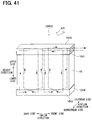
- FIG. 41 is a diagram schematically illustrating the flow of refrigerant in an evaporator according to a modification of the seventh embodiment.
- FIG. 42 is a plan view schematically illustrating the flow of refrigerant in the evaporator illustrated in FIG. 41 .
- FIG. 43 is a sectional view schematically illustrating the shape of an inner fin which functions as a heat transfer suppressor in an evaporator according to an eighth embodiment.
- FIG. 44 is a sectional view taken along a line A 7 -A 7 in FIG. 43 .
- FIG. 45 is a sectional view taken along a line B 7 -B 7 in FIG. 43 .
- FIG. 46 is a sectional view schematically illustrating the shape of a cold storage material container which functions as a heat transfer suppressor in an evaporator according to a ninth embodiment.
- FIG. 47 is a sectional view taken along a line A 8 -A 8 in FIG. 46 .
- FIG. 48 is a sectional view taken along a line B 8 -B 8 in FIG. 46 .
- FIG. 49 is a sectional view schematically illustrating the shape of a cold storage material container which functions as a heat transfer suppressor in an evaporator according to a tenth embodiment.
- FIG. 50 is a sectional view taken along a line A 9 -A 9 in FIG. 49 .
- FIG. 51 is a sectional view taken along a line B 9 -B 9 in FIG. 49 .
- FIG. 52 is a plan view schematically illustrating the flow of refrigerant in an evaporator according to an eleventh embodiment.
- FIG. 53 is a plan view schematically illustrating the flow of refrigerant in an evaporator according to a twelfth embodiment.
- FIG. 54 is a plan view schematically illustrating the flow of refrigerant in an evaporator according to a thirteenth embodiment.
- FIG. 55 is a schematic view illustrating an internal structure of a cold storage material container of an evaporator according to a fourteenth embodiment.
- FIG. 56 is a schematic view illustrating a structure of a cold storage material container of an evaporator according to a fifteenth embodiment.
- a refrigerating cycle apparatus 1 is used in a vehicle air conditioner. As illustrated in FIG. 1 , the refrigerating cycle apparatus 1 includes a compressor 10 , a radiator 20 , a pressure reducer 30 , and an evaporator 40 . These components are annularly connected to each other through piping to constitute a refrigerant circulation passage. In the refrigerating cycle apparatus 1 , a cold storage heat exchanger according to the first embodiment is used as the evaporator 40 . In the following description, the cold storage heat exchanger 40 according to the present embodiment is also referred to as the “evaporator 40 ”.
- the compressor 10 is driven by an internal combustion engine which is a power source 2 for traveling of a vehicle. Thus, when the power source 2 comes to a stop, the compressor 10 also comes to a stop.
- the compressor 10 draws a refrigerant from the evaporator 40 , compresses the drawn refrigerant, and ejects the compressed refrigerant to the radiator 20 .
- the radiator 20 cools the high-temperature refrigerant.
- the radiator 20 is also called a condenser.
- the pressure reducer 30 reduces the pressure of the refrigerant cooled by the radiator 20 .
- the pressure reducer 30 may be provided as a fixed orifice, a temperature expansion valve, or an ejector.
- the evaporator 40 evaporates the refrigerant with the pressure reduced by the pressure reducer 30 and cools a medium.
- the evaporator 40 cools air supplied to a vehicle cabin.
- the refrigerating cycle apparatus 1 may further include an internal heat exchanger which performs heat exchange between a high-pressure side liquid refrigerant and a low-pressure side gas refrigerant and a tank element such as a receiver or an accumulator which stores an excessive refrigerant.
- the power source 2 may be provided as an internal combustion engine or an electric motor.
- an up-down direction on the sheets of FIGS. 2 and 3 is referred to as a “height direction”, an upper side in the height direction is referred to as an “upper side”, and a lower side in the height direction is referred to as a “lower side”.
- the height direction is typically the gravity direction, the height direction may be another direction.
- a right-left direction on the sheet of FIG. 3 is referred to as an “airflow direction” in which air flows through an air passage 53 , a left side in the airflow direction is referred to as an “upstream side”, and a right side in the airflow direction is referred to as a “downstream side”.
- the evaporator 40 includes a refrigerant passage member which has a plurality of branches.
- the refrigerant passage member is provided as a passage member made of metal such as aluminum.
- the refrigerant passage member includes a first header 41 , a second header 42 , a third header 43 , and a fourth header 44 which are positioned in pairs, and a plurality of refrigerant tubes 45 which couple the headers.
- the first header 41 , the second header 42 , the third header 43 , and the fourth header 44 extend in the inflow direction.
- the refrigerant tubes 45 extend in the height direction which is perpendicular to the inflow direction.
- the first header 41 is paired with the second header 42 .
- the first header 41 and the second header 42 are disposed apart from each other by a predetermined distance in the height direction and parallel to each other in the inflow direction.
- the third header 43 is paired with the fourth header 44 .
- the third header 43 and the fourth header 44 are disposed apart from each other by a predetermined distance in the height direction and parallel to each other in the inflow direction.
- the first header 41 and the third header 43 are disposed on the upper side in the height direction.
- the second header 42 and the fourth header 44 are disposed on the lower side in the height direction.
- a plurality of refrigerant tubes 45 are arrayed at regular intervals between the first header 41 and the second header 42 .
- Each of the refrigerant tubes 45 communicates with the inside of the first header 41 and the inside of the second header 42 at one end thereof.
- the first header 41 , the second header 42 , and the refrigerant tubes 45 disposed between the first header 41 and the second header 42 form a first heat exchange unit 48 .
- a plurality of refrigerant tubes 45 are arrayed at regular intervals between the third header 43 and the fourth header 44 .
- Each of the refrigerant tubes 45 communicates with the inside of the third header 43 and the inside of the fourth header 44 at the other end thereof.
- the third header 43 , the fourth header 44 , and the refrigerant tubes 45 disposed between the third header 43 and the fourth header 44 form a second heat exchange unit 49 .
- the evaporator 40 includes the first heat exchange unit 48 and the second heat exchange unit 49 which are disposed in two layers.
- the second heat exchange unit 49 is disposed at the upstream side
- the first heat exchange unit 48 is disposed at the downstream side.
- the refrigerant tubes 45 are disposed in two rows in the inflow direction so as to be paired in the airflow direction.
- a joint as a refrigerant inlet is disposed at an end (the end at the front side in the inflow direction) of the first header 41 .
- the inside of the first header 41 is partitioned into a first section and a second section by a partition plate which is disposed at substantially the center in the length direction (inflow direction) of the first header 41 .
- the refrigerant tubes 45 are divided into a first group G 1 corresponding to the first section and a second group G 2 corresponding to the second section.
- the refrigerant is supplied to the first section of the first header 41 .
- the refrigerant is distributed to the refrigerant tubes 45 belonging to the first group G 1 from the first section.
- the refrigerant flows into the second header 42 through the refrigerant tubes 45 of the first group G 1 so as to be collected in the second header 42 .
- the refrigerant is redistributed to the refrigerant tubes 45 belonging to the second group G 2 from the second header 42 .
- the refrigerant flows into the second section of the first header 41 through the refrigerant tubes 45 of the second group G 2 . In this manner, a U-shaped flow passage for the refrigerant is formed in the first heat exchange unit 48 .
- a joint as a refrigerant outlet is disposed at an end (the end at the front side in the inflow direction in the present embodiment, but may be an end at the back side) of the third header 43 .
- the inside of the third header 43 is partitioned into a first section and a second section by a partition plate which is disposed at substantially the center in the length direction of the third header 43 .
- the first section of the third header 43 is adjacent to the second section of the first header 41 .
- the first section of the third header 43 communicates with the second section of the first header 41 .
- the refrigerant tubes 45 are divided into a third group G 3 corresponding to the first section and a fourth group G 4 corresponding to the second section.
- the refrigerant flows into the first section of the third header 43 from the second section of the first header 41 .
- the refrigerant is distributed to the refrigerant tubes 45 belonging to the third group G 3 from the first section.
- the refrigerant flows into the fourth header 44 through the refrigerant tubes 45 of the third group G 3 so as to be collected in the fourth header 44 .
- the refrigerant is redistributed to the refrigerant tubes 45 belonging to the fourth group G 4 from the fourth header 44 .
- the refrigerant flows into the second section of the third header 43 through the refrigerant tubes 45 of the fourth group G 4 . In this manner, a U-shaped flow passage for the refrigerant is formed in the second heat exchange unit 49 .
- the refrigerant inside the second section of the third header 43 flows out of the refrigerant outlet and flows toward the compressor 10 .
- the refrigerant tube 45 is a multi-hole tube which includes a plurality of refrigerant passages inside thereof.
- the refrigerant tube 45 is also called a flat tube.
- the multi-hole tube can be obtained by an extrusion method or a method of bending and forming a plate.
- the refrigerant passages extend in the longitudinal direction of the refrigerant tube 45 , and are open on both ends of the refrigerant tube 45 .
- the refrigerant tubes 45 are arranged in rows. In each of the rows, the refrigerant tubes 45 are disposed with the principal faces thereof facing each other.
- the air passage 53 for heat exchange with air or a storage area for storing a cold storage material container 47 (described below) is formed between each adjacent two of the refrigerant tubes 45 .
- the evaporator 40 includes a fin member for increasing the contact area with air supplied to the vehicle cabin.
- the fin member is provided as a plurality of fins 46 each having a corrugated shape.
- Each of the fins 46 is disposed in the air passage 53 which is formed between two adjacent refrigerant tubes 45 .
- the fin 46 is thermally coupled to the two adjacent refrigerant tubes 45 .
- the fin 46 is joined to the two adjacent refrigerant tubes 45 with a joining material that is excellent in heat transfer. A brazing material can be used as the joining material.
- the fin 46 is made of a thin metal plate, such as a thin aluminum plate, which is formed into a wave shape.
- the fin 46 includes an air passage called a louver.
- the evaporator 40 further includes a plurality of cold storage material containers 47 .
- the cold storage material container 47 is made of metal such as aluminum.
- the cold storage material container 47 has a flat tubular shape.
- the cold storage material container 47 forms a chamber for storing a cold storage material 50 inside thereof by joining two plates having a hollow shape.
- the cold storage material container 47 includes wide principal faces at both sides thereof. Further, two principal walls which form the respective two principal faces are parallel to the refrigerant tubes 45 .
- the cold storage material container 47 is disposed between two adjacent refrigerant tubes 45 .
- the cold storage material container 47 is disposed between the two refrigerant tubes 45 which are adjacent to each other in the inflow direction.
- the cold storage material container 47 is thermally coupled to the two refrigerant tubes 45 disposed on both sides thereof.
- the cold storage material container 47 is joined to the two adjacent refrigerant tubes 45 with a joining material that is excellent in heat transfer.
- a brazing material or a resin material such as an adhesive can be used as the joining material.
- the cold storage material container 47 is brazed to the refrigerant tubes 45 .
- the brazing material is disposed between the cold storage material container 47 and each of the refrigerant tubes 45 so as to couple the cold storage material container 47 and the refrigerant tubes 45 through a large sectional area.
- brazing material a material clad with a brazing material may be used, or a brazing material foil may be disposed between the cold storage material container 47 and each of the refrigerant tubes 45 .
- a brazing material foil may be disposed between the cold storage material container 47 and each of the refrigerant tubes 45 .
- excellent heat transfer is exhibited between the cold storage material container 47 and the refrigerant tubes 45 .
- the surface of the cold storage material container 47 may have recesses and projections, and the projections may be joined to the refrigerant tubes 45 .
- the refrigerant tubes 45 are arranged at substantially regular intervals. A plurality of spaces are formed between the refrigerant tubes 45 .
- the fins 46 and the cold storage material containers 47 are arranged in the spaces with a predetermined regularity.
- FIGS. 2 and 8 illustrate a structure in which two fins 46 (air passages 53 ) and one cold storage material container 47 are repeatedly arranged in this order. However, an arrangement other than the illustrated arrangement may be employed. Some of the spaces serve as the air passages 53 . The remaining spaces serve as the storage areas.
- the fins 46 are disposed in the respective air passages 53 .
- the cold storage material containers 47 are disposed in the respective storage areas.
- Each of two refrigerant tubes 45 that are located on both sides of the cold storage material container 47 defines the air passage for heat exchange with air at the side opposite to the cold storage material container 47 .
- two refrigerant tubes 45 are disposed between two fins 46 , and one cold storage material container 47 is further disposed between the two refrigerant tubes 45 . It is possible to transfer heat of the refrigerant to the cold storage material 50 without receiving a heat load of air flowing through the fin 46 by the cold storage material container 47 disposed between the two refrigerant tubes 45 . Thus, the cold storage efficiency is improved.
- One cold storage material container 47 and two refrigerant tubes 45 located on both sides of the cold storage material container 47 constitute one cold storage unit.
- a plurality of cold storage units having the same structure are arranged on the evaporator 40 .
- the cold storage units are arranged at regular intervals. Further, the cold storage units are equally arranged right and left. Furthermore, the cold storage units are symmetrically arranged right and left.
- the cold storage material container 47 is joined to both of the refrigerant tubes 45 of the first heat exchange unit 48 and the second heat exchange unit 49 in the airflow direction.
- the cold storage material container 47 includes an outer shell 47 a .
- the outer shell 47 a is made of a plate material which is formed into a flat tubular shape.
- An inner fin 47 b having a corrugated shape is stored in the outer shell 47 a .
- the inner fin 47 b is made of a metal plate, such as a thin aluminum plate, which is formed into a wave shape like the fin 46 .
- a plurality of tops of the inner fin 47 b are brazed to the inner faces of principal walls (the walls whose outer surfaces are principal faces joined to the refrigerant tubes 45 ) on both sides in the inflow direction of the outer shell 47 a .
- the inner fin 47 b extends in the longitudinal direction (height direction) of the cold storage material container 47 . Peaks and valleys of the inner fin 47 b extend in the airflow direction. With such a structure, the inner fin 47 b increases the contact area between the cold storage material 50 and the cold storage material container 47 . Details of the shape of the inner fin 47 b will be described below.
- the first header 41 is also referred to as an inlet side passage which includes an inlet of the refrigerant passage.
- the third header 43 is also referred to as an outlet side passage which includes an outlet of the refrigerant passage.
- the first header 41 and the third header 43 are disposed in parallel in the airflow direction at the same position in the height direction and collectively referred to as a first header tank 51 .
- the second header 42 and the fourth header 44 are disposed in parallel in the airflow direction at the same position in the height direction and collectively referred to as a second header tank 52 .
- a refrigerant flowing into the first section of the first header 41 flows into the first section of the second header 42 through the refrigerant tubes 45 of the first group G 1 (first turn).
- the refrigerant flowing into the first section of the second header 42 flows into the second section of the second header 42 .
- the refrigerant flowing into the second section of the second header 42 flows into the second section of the first header 41 through the refrigerant tubes 45 of the second group G 2 (second turn).
- the second section of the first header 41 and the second section of the third header 43 communicate with each other.
- the refrigerant flowing into the second section of the first header 41 flows into the second section of the third header 43 .
- the refrigerant flowing into the second section of the third header 43 flows into the second section of the fourth header 44 through the refrigerant tubes 45 of the third group G 3 (third turn).
- the refrigerant flowing into the second section of the fourth header 44 flows into the first section of the fourth header 44 .
- the refrigerant flowing into the first section of the fourth header 44 flows into the first section of the third header 43 through the refrigerant tubes 45 of the fourth group G 4 (fourth turn).
- the refrigerant flowing into the first section of the third header 43 flows out to the outside. That is, the evaporator 40 of the present embodiment is configured to include a so-called four-turn type refrigerant passage.
- the compressor 10 for compressing and ejecting the refrigerant is typically present on the downstream side in the flow of the refrigerant relative to the evaporator 40 .
- a return of the refrigerant in a liquid state to the compressor 10 causes a failure.
- the refrigerant forms a single gas layer near the outlet of the refrigerant passage, and the pressure thereof exceeds the saturated vapor pressure.
- FIG. 7 illustrates an example of the characteristics of the refrigerant temperature in the four-turn type refrigerant passage.
- the horizontal axis of FIG. 7 represents the position in the refrigerant passage.
- the left side (an origin point side) of the horizontal axis corresponds to the inlet, and the right side thereof corresponds to the outlet.
- the vertical axis of FIG. 7 represents the refrigerant temperature in each passage position.
- the refrigerant temperature decreases after the refrigerant is introduced into the refrigerant passage.
- the refrigerant temperature rapidly transitions to a high temperature at a substantially intermediate position in the fourth turn (that is, the fourth group G 4 ), and the overheated area S is formed in a part thereafter.
- the overheated area S is formed in a substantially half area on the upper side in the height direction in the refrigerant tubes 45 of the fourth group G 4 .
- the cold storage material container 47 is joined to both of the refrigerant tubes 45 of the first heat exchange unit 48 and the second heat exchange unit 49 in the airflow direction.
- cold storage is interrupted at the refrigerant tubes 45 of the fourth group G 4 , due to the influence of the overheated area S, that is, cold storage is interrupted only in the cold storage material 50 in a part that is in contact with the refrigerant tubes 45 on the upstream side in the airflow direction.
- a blowout temperature between the back side and the front side in the inflow direction (that is, between an area that does not include the overheated area S and an area that includes the overheated area S) during cold release.
- the inner fin 47 b has a shape that is not joined to the cold storage material container 47 in the overheated area S of the refrigerant.
- the inner fin 47 b is not joined to the inner wall surface of the outer shell 47 a of the cold storage material container 47 in a part that is in contact with the overheated area S of the refrigerant tube 45 and is joined to the inner wall surface in a part that is in contact with an area other than the overheated area S of the refrigerant tube 45 .
- a part where the tops of the inner fin 47 b are joined to the cold storage material container 47 is indicated by solid lines, and a part where the tops of the inner fin 47 b are not joined to the cold storage material container 47 is indicated by dotted lines.
- the plurality of refrigerant tubes 45 include at least two refrigerant tubes 45 disposed in the airflow direction of air in the air passages 53 .
- the cold storage material container 47 is joined to the at least two refrigerant tubes 45 disposed in the airflow direction.
- the joined part may have recesses and projections, and the projections may be joined to the refrigerant tubes 45 .
- the inner fin 47 b overlaps the at least two refrigerant tubes 45 when viewed in an array direction of the refrigerant tubes 45 and the cold storage material container 47 (inflow direction).
- the cold storage material container 47 which is joined to the at least two refrigerant tubes 45 including the refrigerant tube 45 having the overheated area S includes a part that is in contact with the overheated area S of the refrigerant tube 45 .
- the inner fin 47 b is not joined to the inner wall of the cold storage material container 47 in an area that overlaps the part, and is joined to the inner wall of the cold storage material container 47 in the other area.
- the inner fin 47 b is not joined to the cold storage material container 47 , that is, the refrigerant tubes 45 in the overheated area S. Thus, heat from the overheated refrigerant is less likely to be transferred to the inside of the cold storage material 50 . Further, the inner fin 47 b itself is disposed (is floating) inside the cold storage material container 47 also in the overheated area S. Thus, cold of the refrigerant in a non-overheated area is transferred also to the cold storage material 50 in the overheated area through the inner fin 47 b .
- the inner fin 47 b is not joined to the cold storage material container 47 in the overheated area S. Accordingly, the inner fin 47 b functions as a “heat transfer suppressor” which suppresses heat transfer from the refrigerant tube 45 to the cold storage material 50 in the overheated area S which is formed by evaporation of the refrigerant near the outlet of the refrigerant passage. Further, the inner fin 47 b having such a structure makes it possible to suppress heat transfer from the refrigerant tube 45 to the cold storage material 50 in the overheated area S and avoid a situation in which the cold storage material 50 is less cooled due to the influence of the overheated area S where the refrigerant temperature becomes high. As a result, the evaporator 40 as the cold storage heat exchanger of the first embodiment is capable of ensuring the cold storage performance by reducing the influence of the overheated area S even when there is the overheated area S.
- the inner fin 47 b is not joined to the inner wall surface of the outer shell 47 a of the cold storage material container 47 in the part that is in contact with the overheated area S of the refrigerant tube 45 and is joined to the inner wall surface in the part that is in contact with the area other than the overheated area S of the refrigerant tube 45 .
- an inner fin 471 b may be joined to an inner wall surface of an outer shell 471 a of a cold storage material container 471 with a relatively low joining ratio in a part that is in contact with the overheated area S of the refrigerant tube 45 and joined to the inner wall surface with a relatively high joining ratio in a part that is in contact with an area other than the overheated area S of the refrigerant tube 45 .
- the “relatively low joining ratio” indicates that the number of peaks and valleys of the inner fin 471 b that are joined to the inner wall surface of the outer shell 471 a is relatively small.
- the “relatively high joining ratio” indicates that the number of peaks and valleys of the inner fin 471 b that are joined to the inner wall surface of the outer shell 471 a is relatively large.
- the evaporator 401 is capable of suppressing heat transfer from the refrigerant tube 45 to the cold storage material 50 in the overheated area S by making the heat transfer amount through the inner fin 471 b in the overheated area S relatively small or making the joining ratio between the inner fin 471 b and the cold storage material container 471 relatively low in this manner. As a result, it is possible to obtain an effect similar to the effect of the evaporator 40 of the first embodiment.
- the corrugated shape of the inner fin 47 b is continuous in the longitudinal direction (height direction) of the cold storage material container 47 , that is, the peaks and the valleys of the inner fin 47 b extend in the airflow direction.
- the corrugated shape of the inner fin 47 b may be continuous in a direction different from the above direction.
- the corrugated shape of an inner fin 472 b may be continuous in the short direction (airflow direction) of a cold storage material container 472 , that is, peaks and valleys of the inner fin 472 b may extend in the height direction.
- the peaks and valleys of the inner fin 472 b are not joined to an inner wall surface of an outer shell 472 a of the cold storage material container 472 in a part that is in contact with the overheated area S of the refrigerant tube 45 in the height direction and are joined to the inner wall surface in a part that is in contact with an area other than the overheated area S of the refrigerant tube 45 . Accordingly, the evaporator 402 is capable of suppressing heat transfer from the refrigerant tube 45 to the cold storage material 50 in the overheated area S. As a result, it is possible to obtain an effect similar to the effect of the evaporator 40 of the first embodiment.
- the four-turn type has been described as an example of the structure of the refrigerant passage inside the evaporator 40 .
- the present disclosure is not limited thereto.
- a first header 41 A, a second header 42 A, a third header 43 A, and a fourth header 44 A there may be no section inside a first header 41 A, a second header 42 A, a third header 43 A, and a fourth header 44 A.
- a refrigerant flowing into the first header 41 A flows into the second header 42 A through the refrigerant tubes 45 of the first heat exchange unit 48 (first turn).
- the second header 42 A and the fourth header 44 A communicate with each other.
- the refrigerant flowing into the second header 42 A flows into the fourth header 44 A.
- the refrigerant flowing into the fourth header 44 A flows into the third header 43 A through the refrigerant tubes 45 of the second heat exchange unit 49 (second turn).
- the refrigerant flowing into the third header 43 A flows out to the outside. That is, the cold storage heat exchanger 40 A is configured to include a so-called two-turn type refrigerant passage.
- FIG. 16 illustrates an example of the characteristics of a refrigerant temperature in the two-turn type refrigerant passage.
- the refrigerant temperature decreases after the refrigerant is introduced into the refrigerant passage.
- the refrigerant temperature rapidly transitions to a high temperature at a position in the second half of the second turn, and an overheated area S is formed in the following part.
- the overheated area S is formed in an area on the upper side in the height direction in refrigerant tubes 45 of the second heat exchange unit 49 .
- the inner fin 47 b of the first embodiment can also be used in a cold storage heat exchanger that forms the flow of a refrigerant as formed in the cold storage heat exchanger 40 A and can function as the heat transfer suppressor.
- the cold storage heat exchange 40 A there is no section inside the first header 41 A, the second header 42 A, the third header 43 A, and the fourth header 44 A. However, there may be more sections inside the headers.
- each of a first header 41 B, a second header 42 B, a third header 43 B, and a fourth header 44 B is partitioned into three sections.
- the refrigerant flowing into the second section of the first header 41 B flows into a third section of the first header 41 B.
- the refrigerant flowing into the third section of the first header 41 B flows into a third section of the second header 42 B through refrigerant tubes 45 (third turn).
- the third section of the second header 42 B and a third section of the fourth header 44 B communicate with each other.
- the refrigerant flowing into the third section of the second header 42 B flows into the third section of the fourth header 44 B.
- the refrigerant flowing into the third section of the fourth header 44 B flows into a third section of the third header 43 B through refrigerant tubes 45 (fourth turn).
- the refrigerant flowing into the third section of the third header 43 B flows into a second section of the third header 43 B.
- the refrigerant flowing into the second section of the third header 43 B flows into a second section of the fourth header 44 B through refrigerant tubes 45 (fifth turn).
- the refrigerant flowing into the second section of the fourth header 44 B flows into a first section of the fourth header 44 B.
- the refrigerant flowing into the first section of the fourth header 44 B flows into a first section of the third header 43 B through refrigerant tubes 45 (sixth turn).
- the refrigerant flowing into the first section of the third header 43 B flows out to the outside. That is, the cold storage heat exchanger 40 B is configured to include a so-called six-turn type refrigerant passage.
- the inner fin 47 b of the first embodiment can also be used in a cold storage heat exchanger that forms the flow of a refrigerant as formed in the cold storage heat exchanger 40 B and can function as the heat transfer suppressor.
- the inlet and the outlet for the refrigerant are formed on the first headers 41 , 41 A, 41 B and the third headers 43 , 43 A, 43 B which are disposed on the upper side in the gravity direction (height direction).
- the inlet and the outlet for the refrigerant are not limited to the above form.
- the cold storage heat exchangers 40 , 40 A, 40 B may be configured upside down.
- a first header 41 R and a third header 43 R are disposed on the lower side in the gravity direction (height direction), and a second header 42 R and a fourth header 44 R are disposed on the upper side in the gravity direction.
- a refrigerant flowing into a first section of the first header 41 R flows into a first section of the second header 42 R through refrigerant tubes 45 (first turn).
- the refrigerant flowing into the first section of the second header 42 R flows into a second section of the second header 42 R.
- the refrigerant flowing into the second section of the second header 42 R flows into a second section of the first header 41 R through refrigerant tubes 45 (second turn).
- the second section of the first header 41 R and a second section of the third header 43 R communicate with each other.
- the refrigerant flowing into the second section of the first header 41 R flows into the second section of the third header 43 R.
- the refrigerant flowing into the second section of the third header 43 R flows into a second section of the fourth header 44 R through refrigerant tubes 45 (third turn).
- the refrigerant flowing into the second section of the fourth header 44 R flows into a first section of the fourth header 44 R.
- the refrigerant flowing into the first section of the fourth header 44 R flows into a first section of the third header 43 R through the refrigerant tubes 45 (fourth turn).
- the refrigerant flowing into the first section of the third header 43 R flows out to the outside. That is, the cold storage heat exchanger 40 R is configured to include a so-called four-turn type refrigerant passage in which the arrangement of the cold storage heat exchanger 40 is reversed in the height direction.
- a cold storage heat exchanger 40 RA illustrated in FIG. 19 is upside down of the cold storage heat exchanger 40 A illustrated in FIG. 13 .
- the cold storage heat exchanger 40 RA includes a so-called two-turn type refrigerant passage.
- a first header 41 RA and a third header 43 RA are disposed on the lower side in the gravity direction (height direction).
- a second header 42 RA and a fourth header 44 RA are disposed on the upper side in the gravity direction.
- a cold storage heat exchanger 40 RB illustrated in FIG. 20 is upside down of the cold storage heat exchanger 40 B illustrated in FIG. 17 .
- the cold storage heat exchanger 40 RB includes a so-called six-turn type refrigerant passage.
- a first header 41 RB and a third header 43 RB are disposed on the lower side in the gravity direction (height direction).
- a second header 42 RB and a fourth header 44 RB are disposed on the upper side in the gravity direction.
- An evaporator 140 of the second embodiment differs from the evaporator 40 of the first embodiment in the structure of a heat transfer suppressor which suppresses heat transfer from a refrigerant tube 45 to a cold storage material 50 in an overheated area S.
- the shape of a cold storage material container 147 has a structure that is not joined to the refrigerant tube 45 in the overheated area S of a refrigerant, and the cold storage material container 147 having the above structure functions as the heat transfer suppressor.
- the evaporator 140 of the second embodiment differs from the evaporator 40 of the first embodiment also in that no inner fin is disposed inside the cold storage material container 147 .
- the cold storage material container 147 which is joined to the refrigerant tube 45 having the overheated area S is separated from the refrigerant tube 45 without being joined to the refrigerant tube 45 in a part (area 147 c ) that is in contact with the overheated area S of the refrigerant tube 45 and joined to the refrigerant tube 45 in a part (outer shell 147 a ) that is in contact with an area other than the overheated area S of the refrigerant tube 45 .
- 21 and 22 illustrate, as an example of such a structure, a shape in which the surface of the area 147 c which overlaps the overheated area S in the outer shell 147 a of the cold storage material container 147 is recessed in a direction separating from the refrigerant tube 45 .
- a plurality of refrigerant tubes 45 include at least two refrigerant tubes 45 disposed in the airflow direction of air in an air passage 53 .
- the cold storage material container 147 is joined to the at least two refrigerant tubes 45 which are disposed in the airflow direction.
- the cold storage material container 147 which is joined to the at least two refrigerant tubes 45 including the refrigerant tube 45 having the overheated area S is separated from the refrigerant tubes 45 without being joined to the refrigerant tubes 45 in the area 147 c which includes a part that is in contact with the overheated area S of the refrigerant tube 45 and overlaps the part when viewed in the airflow direction, and the cold storage material container 147 is joined to the refrigerant tubes 45 in an area 147 a other than the area 147 c.
- the cold storage material container 147 is not joined to the refrigerant tubes 45 in the overheated area S. Thus, heat from the overheated refrigerant is less likely to be transferred to the inside of the cold storage material 50 . Further, the cold storage material container 147 itself is in contact with a non-overheated area. Thus, cold of the refrigerant in the non-overheated area is transferred also to the cold storage material 50 in the overheated area S. Accordingly, the evaporator 140 of the second embodiment is capable of achieving an effect similar to the effect of the evaporator 40 of the first embodiment.
- the shape of the cold storage material container 147 of the second embodiment is not limited to the above shape and may have another structure that makes a heat transfer amount from the refrigerant tube 45 to the cold storage material 50 through the cold storage material container 147 in the overheated area S relatively smaller than a heat transfer amount in an area other than the overheated area S. In other words, it may only be required to make the heat transfer performance of the cold storage material container 147 in the overheated area S relatively lower than that in the other part. For example, as illustrated in FIG.
- a cold storage material container 1471 is jointed to the refrigerant tube 45 with a relatively low joining ratio in a part (area 1471 c ) that is in contact with the overheated area S of the refrigerant tube 45 and joined to the refrigerant tube 45 with a relatively high joining ratio in a part (outer shell 1471 a ) that is in contact with an area other than the overheated area S of the refrigerant tube 45 .
- the “relatively low joining ratio” indicates that the ratio of a part joined to the refrigerant tube 45 in the outer surface of the cold storage material container 1471 is relatively small.
- the “relatively high joining ratio” indicates that the ratio of a part joined to the refrigerant tube 45 in the outer surface of the cold storage material container 1471 is relatively large.
- the evaporator 1401 is capable of suppressing heat transfer from the refrigerant tube 45 to the cold storage material 50 in the overheated area S by making the heat transfer amount of the cold storage material container 1471 in the overheated area S relatively small or making the joining ratio between the cold storage material container 1471 and the refrigerant tube 45 in the overheated area relatively low in this manner. As a result, it is possible to obtain an effect similar to the effect of the evaporator 40 of the first embodiment.
- An evaporator 240 of the third embodiment differs from the evaporator 40 of the first embodiment in the structure of a heat transfer suppressor which suppresses heat transfer from a refrigerant tube 45 to a cold storage material 50 in an overheated area S.
- the shape of a cold storage material container 247 has a structure that is not joined to the refrigerant tube 45 in the overheated area S of the refrigerant, and the cold storage material container 247 having the structure functions as the heat transfer suppressor.
- the evaporator 240 of the third embodiment differs from the evaporator 40 of the first embodiment also in that an inner fin 247 b which is disposed inside the cold storage material container 247 is joined to an inner wall surface of an outer shell 247 a over the entire area in the longitudinal direction.
- the inner fin 247 b extends in the longitudinal direction (height direction) inside the cold storage material container 247 , and is joined to an inner wall of the cold storage material container 247 .
- the cold storage material container 247 which is joined to the refrigerant tube 45 having the overheated area S is separated from the refrigerant tube 45 without being joined to the refrigerant tube 45 in a part (area 247 c ) that is in contact with the overheated area S of the refrigerant tube 45 and joined to the refrigerant tube 45 in a part (outer shell 147 a ) that is in contact with an area other than the overheated area S of the refrigerant tube 45 .
- a plurality of refrigerant tubes 45 include at least two refrigerant tubes 45 disposed in the airflow direction of air in an air passage 53 .
- the cold storage material container 247 is joined to the at least two refrigerant tubes 45 which are disposed in the airflow direction.
- the inner fin 247 b overlaps the at least two refrigerant tubes 45 when viewed in an array direction (inflow direction) of the refrigerant tubes 45 and the cold storage material container 247 .
- the cold storage material container 247 which is joined to the at least two refrigerant tubes 45 including the refrigerant tube 45 having the overheated area S is separated from the refrigerant tubes 45 without being joined to the refrigerant tubes 45 in the area 247 c which includes a part that is in contact with the overheated area S of the refrigerant tube 45 and overlaps the part when viewed in the airflow direction and joined to the refrigerant tubes 45 in an area 247 a other than the area 247 c.
- the cold storage material container 247 is not joined to the refrigerant tubes 45 in the overheated area S. Further, the inner fin 247 b which is joined to the inside of the cold storage material container 247 is also not joined to the refrigerant tubes 45 . Thus, heat from the overheated refrigerant is less likely to be transferred to the inside of the cold storage material 50 .
- the inner fin 247 b itself is disposed also inside the cold storage material container 47 in the overheated area S. Thus, cold of the refrigerant in a non-overheated area is transferred also to the cold storage material 50 in the overheated area S through the inner fin 247 b . Further, the cold storage material container 247 itself is in contact with the non-overheated area.
- the evaporator 240 of the third embodiment is capable of achieving an effect similar to the effect of the evaporator 40 of the first embodiment.
- the evaporator 240 of the third embodiment may also have a structure in which the inner fin 247 b is not joined to the inner wall surface of the outer shell 247 a of the cold storage material container 247 in a part that is in contact with the overheated area S of the refrigerant tube 45 similarly to the first embodiment.
- the inner fin 247 b is not joined to the cold storage material container 247 , that is, the refrigerant tube 45 in the overheated area S, heat from the overheated refrigerant is further less likely to be transferred to the inside of the cold storage material 50 .
- the shape of the cold storage material container 247 of the third embodiment is not limited to the above shape and may have another structure that makes a heat transfer amount from the refrigerant tube 45 to the cold storage material 50 through the cold storage material container 247 in the overheated area S relatively smaller than a heat transfer amount in an area other than the overheated area S. In other words, it may only be required to make the heat transfer performance of the cold storage material container 247 in the overheated area S relatively lower than that in the other part.
- the structure described in the second embodiment with reference to FIG. 23 as illustrated in FIG.
- a cold storage material container 2471 may be jointed to the refrigerant tube 45 with a relatively low joining ratio in a part (area 2471 c ) that is in contact with the overheated area S of the refrigerant tube 45 and joined to the refrigerant tube 45 with a relatively high joining ratio in a part (outer shell 2471 a ) that is in contact with an area other than the overheated area S of the refrigerant tube 45 .
- the evaporator 2401 is capable of suppressing heat transfer from the refrigerant tube 45 to the cold storage material 50 in the overheated area S by making the heat transfer amount of the cold storage material container 2471 in the overheated area S relatively small or making the joining ratio between the cold storage material container 2471 and the refrigerant tube 45 in the overheated area S relatively low in this manner. As a result, it is possible to obtain an effect similar to the effect of the evaporator 40 of the first embodiment.
- the inner fin 2471 b may be joined to the inner wall surface of the outer shell 2471 a of the cold storage material container 2471 with a relatively low joining ratio in a part that is in contact with the overheated area S of the refrigerant tube 45 and joined to the inner wall surface with a relatively high joining ratio in a part that is in contact with an area other than the overheated area S of the refrigerant tube 45 .
- the evaporator 2401 is capable of suppressing heat transfer from the refrigerant tube 45 to the cold storage material 50 in the overheated area S also by making the joining ratio between the inner fin 2471 b and the cold storage material container 2471 relatively low in this manner. As a result, it is possible to obtain an effect similar to the effect of the evaporator 40 of the first embodiment.
- the corrugated shape of the inner fin 247 b may be continuous in the short direction (airflow direction) of the cold storage material container 247 , that is, peaks and valleys of the inner fin 247 b may extend in the height direction.
- the evaporator 240 is capable of suppressing heat transfer from the refrigerant tube 45 to the cold storage material 50 in the overheated area S. As a result, it is possible to obtain an effect similar to the effect of the evaporator 40 of the first embodiment.
- a fourth embodiment will be described with reference to FIGS. 27 and 28 .
- the shape of an inner fin 347 b as the heat transfer suppressor differs from the shape of the inner fin 47 b in the evaporator 40 of the first embodiment.
- an overheated area S is typically formed on the upstream side.
- the fourth embodiment differs from the first embodiment in that the inner fin 347 b is not joined to a cold storage material container 347 only on the upstream side.
- a plurality of refrigerant tube 45 include at least two refrigerant tubes 45 disposed in the airflow direction of air in an air passage 53 .
- the cold storage material container 347 is joined to the at least two refrigerant tubes which are disposed in the airflow direction.
- the inner fin 347 b overlaps the at least two refrigerant tubes 45 when viewed in an array direction (inflow direction) of the refrigerant tubes 45 and the cold storage material container 347 .
- the inner fin 347 b is joined to the inner wall of the cold storage material container 347 over the entire area in the longitudinal direction in an area overlapping the refrigerant tube 45 having no overheated area S. Further, in an area overlapping the refrigerant tube 45 having the overheated area S, the inner fin 347 b is not joined to the inner wall of the cold storage material container 347 in a part that is in contact with the overheated area S of the refrigerant tube 45 and joined to the inner wall of the cold storage material container 347 in the other part.
- the evaporator 340 achieves an effect similar to the effect of the first embodiment. Further, since the inner fin 347 b is in contact with the refrigerant tube 45 in a non-overheated area on the downstream side, cold can be transferred from the upstream side to the downstream side. Thus, it is possible to further suppress heat transfer from the refrigerant tube 45 to the cold storage material 50 .
- a fifth embodiment will be described with reference to FIGS. 29 and 30 .
- the shape of a cold storage material container 447 as the heat transfer suppressor differs from the shape of the cold storage material container 147 in the evaporator 140 of the second embodiment.
- an overheated area S is typically formed on the upstream side.
- the fifth embodiment differs from the second embodiment in that the cold storage material container 447 is not joined to the refrigerant tubes 45 only on the upstream side.
- a plurality of refrigerant tubes 45 include at least two refrigerant tubes 45 disposed in the airflow direction of air in an air passage 53 .
- the cold storage material container 447 is joined to the at least two refrigerant tubes 45 which are disposed in the airflow direction.
- the cold storage material container 447 which is joined to the at least two refrigerant tubes 45 including the refrigerant tube 45 having the overheated area S is joined to the refrigerant tubes 45 over the entire area in the extending direction (height direction) in an area overlapping the refrigerant tube 45 having no overheated area S.
- the cold storage material container 447 is separated from the refrigerant tubes 45 without being joined to the refrigerant tubes 45 in a part (area 447 c ) that is in contact with the overheated area S of the refrigerant tube 45 and joined to the refrigerant tube 45 in a part 447 a other than the area 447 c.
- the evaporator 440 of the fifth embodiment achieves an effect similar to the effect of the second embodiment. Further, since the cold storage material container 447 is in contact with the refrigerant tube 45 in a non-overheated area on the downstream side, cold can be transferred from the upstream side to the downstream side. Thus, it is possible to further suppress heat transfer from the refrigerant tube 45 to the cold storage material 50 . Further, the capacity of the cold storage material container 447 can be increased compared to that of the second embodiment. Thus, it is possible to store a larger amount of cold storage material 50 .
- a sixth embodiment will be described with reference to FIGS. 31 and 32 .
- the shape of a cold storage material container 547 as the heat transfer suppressor differs from the shape of the cold storage material container 247 in the evaporator 240 of the third embodiment.
- an overheated area S is typically formed on the upstream side.
- the sixth embodiment differs from the third embodiment in that the cold storage material container 547 is not joined to the refrigerant tubes 45 only on the upstream side.
- a plurality of refrigerant tubes 45 include at least two refrigerant tubes 45 disposed in the airflow direction of air in an air passage 53 .
- the cold storage material container 547 is joined to the at least two refrigerant tubes 45 which are disposed in the airflow direction.
- An inner fin 547 b overlaps the at least two refrigerant tubes 45 when viewed in an array direction (inflow direction) of the refrigerant tubes 45 and the cold storage material container 547 .
- the cold storage material container 547 which is joined to the at least two refrigerant tubes 45 including the refrigerant tube 45 having the overheated area S is joined to the refrigerant tube 45 over the entire area in the extending direction (height direction) in an area overlapping the refrigerant tube 45 having no overheated area S. Further, in an area overlapping the refrigerant tube 45 having the overheated area S, the cold storage material container 547 is separated from the refrigerant tube 45 without being joined to the refrigerant tube 45 in a part (area 547 c ) that is in contact with the overheated area S of the refrigerant tube 45 and joined to the refrigerant tube 45 in a part 547 a other than the area 547 c.
- the evaporator 540 of the sixth embodiment achieves an effect similar to the effect of the third embodiment. Further, since the cold storage material container 547 and the inner fin 547 b are in contact with the refrigerant tube 45 in a non-overheated area on the downstream side, cold can be transferred from the upstream side to the downstream side. Thus, it is possible to further suppress heat transfer from the refrigerant tube 45 to the cold storage material 50 . Further, the capacity of the cold storage material container 547 can be increased compared to that of the third embodiment. Thus, it is possible to store a larger amount of cold storage material 50 .
- a seventh embodiment will be described with reference to FIGS. 33 to 38 .
- an overheated area S 1 as a subject differs from the overheated area S of the first to sixth embodiments.
- An evaporator 1040 (cold storage heat exchanger) according to the seventh embodiment suppresses heat transfer from a refrigerant tube 45 to a cold storage material 50 in the overheated area S 1 which is formed due to flow rate variations in a refrigerant passage when the flow rate of a refrigerant is low.
- a refrigerant flowing into a first header 2041 flows into a second header 2042 through refrigerant tubes 45 of a first heat exchange unit 48 (first turn).
- the second header 2042 and a fourth header 2044 communicate with each other.
- the refrigerant flowing into the second header 2042 flows into the fourth header 2044 .
- the refrigerant flowing into the fourth header 2044 flows into a third header 2043 through refrigerant tubes 45 of a second heat exchange unit 49 (second turn).
- the refrigerant flowing into the third header 2043 flows out to the outside.
- an overheated area S 1 in an area on the back side in the inflow direction.
- An overheated area S 2 (second overheated area) illustrated in FIG. 37 is an overheated area which is formed near an outlet and a subject in the first to sixth embodiments.
- the evaporator 1040 of the seventh embodiment is characterized in the structure of the refrigerant passage in order to reduce the influence of the overheated area S 1 as described above and ensure a cold storage performance of the cold storage material 50 .
- the evaporator 1040 is similar to the evaporator 1040 of the first embodiment in the basic structure, but differs from the evaporator 1040 of the first embodiment in the structure of the refrigerant passage, more specifically, in sections inside a first header 1041 , a second header 1042 , a third header 1043 , and a fourth header 1044 and a mutual communication relationship therebetween.
- a first section and a second section communicate with each other inside the first header 1041 differently from the first header 41 of the first embodiment.
- a refrigerant supplied to the first header 1041 is distributed to a plurality of refrigerant tubes 45 belonging to a first group G 1 and a second group G 2 .
- the refrigerant flows into a first section of the second header 1042 through the refrigerant tubes 45 of the first group G 1 and flows into a second section of the second header 1042 through the refrigerant tubes 45 of the second group G 2 .
- the second header 1042 differs from the second header 42 of the first embodiment in that the first section and the second section are uncommunicably sealed.
- the fourth header 1044 differs from the fourth header 44 of the first embodiment in that a first section and a second section are uncommunicably sealed.
- the first section of the second header 42 which is located on the front side in the inflow direction and the downstream side in the airflow direction communicates with the first section of the fourth header 1044 which is located on the back side in the inflow direction and the upstream side in the airflow direction.
- the refrigerant flows into the first section of the fourth header 1044 from the first section of the second header 1042 and flows into the second section of the fourth header 1044 from the second section of the second header 1042 .
- a first section and a second section communicate with each other inside the third header 1043 differently from the third header 43 of the first embodiment.
- the refrigerant flowing into the first section of the fourth header 1044 is distributed to a plurality of refrigerant tubes 45 belonging to a third group G 3 .
- the refrigerant flowing into the second section of the fourth header 1044 is distributed to a plurality of refrigerant tubes 45 belonging to a fourth group G 4 .
- the refrigerant flows into the third header 1043 through the refrigerant tubes 45 of the third group G 3 and the fourth group G 4 so as to be collected therein.
- the refrigerant inside the third header 1043 flows out of the refrigerant outlet and flows toward the compressor 10 .
- the refrigerant passage has a structure that changes the position in the inflow direction of the refrigerant introduced from the first header 1041 on the upper side in the height direction in a second header tank 52 on the lower side in the height direction. That is, the position of the refrigerant introduced from the front side in the inflow direction through the refrigerant tubes 45 of the first group G 1 is changed to the back side in the inflow direction. Further, the position of the refrigerant introduced from the back side in the inflow direction through the refrigerant tubes 45 of the second group G 2 is changed to the front side in the inflow direction. As illustrated in FIGS.
- a schematic shape of the refrigerant passage inside the second header tank 52 is an X shape when viewed in the height direction. Further, a schematic shape of the refrigerant passage inside the evaporator 1040 is a crossed shape of two two-turn type refrigerant passages. The structure of the refrigerant passage of the seventh embodiment is referred to as a “flow change type” for convenience.
- the structure of the flow change type refrigerant passage of the seventh embodiment can be described as follows.
- the evaporator 1040 includes a first header tank 51 which is formed in such a manner that refrigerant tubes 45 communicate with the first header tank 51 at one end side thereof and the longitudinal direction of the first header tank 51 is aligned with the array direction (inflow direction) of the refrigerant tubes 45 and the cold storage material container 47 and the second header tank 52 which is formed in such a manner that the refrigerant tubes 45 communicate with the second header tank 52 at the other end side thereof and the longitudinal direction of the second header tank 52 is aligned with the inflow direction.
- the refrigerant tubes 45 are arranged in two rows so as to be paired in the airflow direction of air in the air passage 53 .
- the inside of the first header tank 51 is divided into the first header 1041 and the third header 1043 .
- the first header 1041 is an inlet side passage which communicates with some of the refrigerant tubes 45 disposed on the downstream side in the airflow direction and includes an inlet of the refrigerant passage on one end in the longitudinal direction thereof.
- the third header 1043 is an outlet side passage which communicates with some of the refrigerant tubes 45 disposed on the upstream side in the airflow direction and includes an outlet of the refrigerant passage on one end (or the other end) in the longitudinal direction thereof.
- the refrigerant tubes 45 are divided into the first group G 1 , the second group G 2 , the third group G 3 , and the fourth group G 4 .
- the refrigerant tubes 45 of the first group G 1 communicate with the first header 1041 as the inlet side passage, and are disposed on one end side in the longitudinal direction (the front side in the inflow direction).
- the refrigerant tubes 45 of the second group G 2 communicate with the first header 1041 as the inlet side passage, and are disposed on the other end side in the longitudinal direction (the back side in the inflow direction).
- the refrigerant tubes 45 of the third group G 3 communicate with the third header 1043 as the outlet side passage, and are disposed on the other end side in the longitudinal direction.
- the refrigerant tubes 45 of the fourth group G 4 communicate with the third header 1043 as the outlet side passage, and are disposed on the one end side in the longitudinal direction.
- the second header tank 52 is configured to allow communication between the first group G 1 and the third group G 3 and communication between the second group G 2 and the fourth group G 4 and change the position of a refrigerant introduced to the front side in the inflow direction from the first header 1041 and the position of a refrigerant introduced to the back side in the inflow direction from the first header 1041 to the back side and the front side, respectively, so as to be led to the third header 1043 .
- the overheated area S 1 is formed in the second group G 2 and the fourth group G 4 of the refrigerant tubes 45 due to flow rate variations in the refrigerant passage when the flow rate of the refrigerant is low.
- the refrigerant flows through one of the two refrigerant tubes 45 with a relatively high flow rate. Accordingly, even when the overheated area S 1 is formed on the other one of the two refrigerant tubes 45 to which the cold storage material container 47 is joined, cold in a non-overheated area can be transferred to the cold storage material 50 in the overheated area S 1 . Thus, it is possible to cool the cold storage material 50 inside the cold storage material container 47 in an excellent manner.
- the seventh embodiment is characterized in a refrigerant passage structure 1045 in which a single cold storage material container 47 is joined to both of the refrigerant tube 45 having the overheated area S 1 and the refrigerant tube 45 having no overheated area by changing the position in the inflow direction of the refrigerant in the second header tank 52 by the flow change type refrigerant passage.
- the refrigerant passage structure 1045 functions as a “heat transfer suppressor” which suppresses heat transfer from the refrigerant tube 45 to the cold storage material 50 in the overheated area S 1 which is formed due to flow rate variations in the refrigerant passage when the flow rate of the refrigerant is low.
- the refrigerant passage structure 1045 as described above makes it possible to suppress heat transfer from the refrigerant tube 45 to the cold storage material 50 in the overheated area S 1 and avoid a situation in which the cold storage material 50 is less cooled due to the influence of the overheated area S 1 where the refrigerant temperature becomes high.
- the evaporator 1040 as the cold storage heat exchanger of the seventh embodiment is capable of ensuring the cold storage performance by reducing the influence of the overheated area S 1 even when there is the overheated area S 1 .
- the surface of the cold storage material container 47 may have recesses and projections, and the projections may be joined to the refrigerant tubes 45 .
- one flow change type refrigerant passage that is, the refrigerant passage structure 1045 in which the position in the inflow direction of the refrigerant is changed at one location in the second header tank 52 .
- another structure that includes at least one flow change type refrigerant passage may be employed.
- an evaporator 1040 A illustrated in FIGS. 39 and 40 uses one flow change type refrigerant passage in combination with a conventional two-turn type refrigerant passage.
- An evaporator 1040 B illustrated in FIGS. 41 and 42 uses two flow change type refrigerant passages which are disposed in the inflow direction in combination.
- a plurality of flow change type refrigerant passages may be disposed in the inflow direction.
- the refrigerant passages of the evaporator 1040 A and the evaporator 1040 B also make it possible to achieve a structure similar to the refrigerant passage structure 1045 of the seventh embodiment. Thus, it is possible to achieve an effect similar to the effect of the evaporator 1040 of the seventh embodiment.
- An eight embodiment will be described with reference to FIGS. 43 to 45 .
- An evaporator 1140 of the eighth embodiment differs from the evaporator 1040 of the seventh embodiment in that a function of an inner fin 1147 b is further provided in addition to the structure of the seventh embodiment as the heat transfer suppressor which suppresses heat transfer from the refrigerant tube 45 to the cold storage material 50 in the overheated area 51 which is formed due to flow rate variations in the refrigerant passage when the flow rate of the refrigerant is low.
- a function of an inner fin 1147 b is further provided in addition to the structure of the seventh embodiment as the heat transfer suppressor which suppresses heat transfer from the refrigerant tube 45 to the cold storage material 50 in the overheated area 51 which is formed due to flow rate variations in the refrigerant passage when the flow rate of the refrigerant is low.
- the evaporator 1140 of the eighth embodiment differs from the evaporator 1040 of the seventh embodiment in that, in a cold storage material container 1147 which is in contact with the overheated area 51 (the back and downstream side, the front and upstream side), the inner fin 1147 b is not in contact with the overheated area 51 .
- the inner fin 1147 b extends in the longitudinal direction (height direction) of the cold storage material container 1147 inside the cold storage material container 1147 .
- the inner fin 1147 b is not joined to the inner wall of the cold storage material container 1147 in a part where the cold storage material container 1147 is joined to refrigerant tubes 45 of the second group G 2 and the fourth group G 4 having the overheated area 51 (a cross section taken along line B 7 -B 7 in FIG. 43 ).
- the inner fin 1147 b is joined to the inner wall of the cold storage material container 1147 in a part where the cold storage material container 1147 is in contact with refrigerant tubes 45 of the first group G 1 and the third group G 3 having no overheated area 51 (a cross section taken along line A 7 -A 7 in FIG. 43 ).
- the inner fin 1147 b functions as the heat transfer suppressor.
- the evaporator 1140 of the eighth embodiment achieves an effect similar to the effect of the seventh embodiment. Further, since the inner fin 1147 b is not in contact with the cold storage material container 1147 in the overheated area S 1 , heat in the overheated area S 1 is less likely to be transferred to the cold storage material 50 inside the cold storage material container 1147 . Thus, it is possible to more appropriately cool the cold storage material inside the cold storage material container 1147 with cold in a non-overheated area without the influence of the heat in the overheated area S 1 .
- a joining structure between the inner fin 1147 b and the cold storage material container 1147 of the eighth embodiment is not limited to the above structure and may have another structure that makes a heat transfer amount from the refrigerant tube 45 to the cold storage material 50 through the inner fin 1147 b in the overheated area S 1 relatively smaller than a heat transfer amount in an area other than the overheated area S 1 .
- it may only be required to make the heat transfer performance of the inner fin 1147 b in the overheated area S 1 relatively lower than the other part.
- the inner fin 1171 b may be joined to the inner wall surface of an outer shell 1147 a of the cold storage material container 1147 with a relatively low joining ratio in a part that is in contact with the overheated area S 1 of the refrigerant tube 45 and joined to the inner wall surface with a relatively high joining ratio in a part that is in contact with an area other than the overheated area S 1 of the refrigerant tube 45 .
- the corrugated shape of the inner fin 1147 b may be continuous in the short direction (airflow direction) of the cold storage material container 1147 , that is, peaks and valleys of the inner fin 1147 b may extend in the height direction.
- peaks and valleys of the inner fin 1147 b that are in contact with the overheated area S 1 of the refrigerant tube 45 in the airflow direction are not joined to the inner wall surface of the outer shell 1147 a of the cold storage material container 1147 , and peaks and valleys of the inner fin 1147 b that are in contact with an area other than the overheated area S 1 are joined to the inner wall surface.
- An evaporator 1240 of the ninth embodiment differs from the evaporator 1040 of the seventh embodiment in that a function of a cold storage material container 1247 is also provided in addition to the structure of the seventh embodiment as the heat transfer suppressor which suppresses heat transfer from the refrigerant tube 45 to the cold storage material 50 in the overheated area S 1 which is formed due to flow rate variations in the refrigerant passage when the flow rate of the refrigerant is low. Specifically, as illustrated in FIGS.
- the evaporator 1240 of the ninth embodiment differs from the evaporator 1040 of the seventh embodiment in that the cold storage material container 1247 which is in contact with the overheated area S 1 (the back and downstream side, the front and upstream side) is not joined to the refrigerant tube 45 having the overheated area S 1 . Further, the evaporator 1240 of the ninth embodiment differs from the evaporator 1040 of the seventh embodiment in that no inner fin is disposed inside the cold storage material container 1247 .
- the cold storage material container 1247 is separated from the refrigerant tubes 45 without being joined to the refrigerant tubes 45 in a part that is in contact with refrigerant tubes 45 of the second group G 2 and the fourth group G 4 having the overheated area S 1 (a cross section taken along line B 8 -B 8 in FIG. 46 , an area 1247 c ). Further, the cold storage material container 1247 is joined to the refrigerant tubes 45 in a part that is in contact with refrigerant tubes 45 of the first group G 1 and the third group G 3 having no overheated area S 1 (a cross section taken along line A 8 -A 8 in FIG. 46 , an outer shell 1247 a ).
- the cold storage material container 1247 functions as the heat transfer suppressor.
- the evaporator 1240 of the ninth embodiment achieves an effect similar to the effect of the seventh embodiment. Further, since the cold storage material container 1247 is not in contact with the refrigerant tubes 45 in the overheated area S 1 , heat in the overheated area S 1 is less likely to be transferred to the cold storage material 50 inside the cold storage material container 1247 . Thus, it is possible to more appropriately cool the cold storage material 50 inside the cold storage material container 1247 with cold in a non-overheated area without the influence of the heat in the overheated area S 1 .
- the shape of the cold storage material container 1247 of the ninth embodiment is not limited to the above shape and may have another structure that makes a heat transfer amount from the refrigerant tube 45 to the cold storage material 50 through the cold storage material container 1247 in the overheated area S 1 relatively smaller than a heat transfer amount in an area other than the overheated area S 1 . In other words, it may only be required to make the heat transfer performance of the cold storage material container 1247 in the overheated area S relatively lower than that in the other area.
- the cold storage material container 1247 may be jointed to the refrigerant tube 45 with a relatively low joining ratio in a part (area 1247 c ) that is in contact with the overheated area S 1 of the refrigerant tube 45 and joined to the refrigerant tube 45 with a relatively high joining ratio in a part (outer shell 1247 a ) that is in contact with an area other than the overheated area S 1 of the refrigerant tube 45 .
- An evaporator 1340 of the tenth embodiment differs from the evaporator 1040 of the seventh embodiment in that a function of a cold storage material container 1247 is also provided in addition to the structure of the seventh embodiment as the heat transfer suppressor which suppresses heat transfer from the refrigerant tube 45 to the cold storage material 50 in the overheated area S 1 which is formed due to flow rate variations in the refrigerant passage when the flow rate of the refrigerant is low.
- a function of a cold storage material container 1247 is also provided in addition to the structure of the seventh embodiment as the heat transfer suppressor which suppresses heat transfer from the refrigerant tube 45 to the cold storage material 50 in the overheated area S 1 which is formed due to flow rate variations in the refrigerant passage when the flow rate of the refrigerant is low.
- the evaporator 1340 of the tenth embodiment differs from the evaporator 1040 of the seventh embodiment in that the cold storage material container 1247 which is in contact with the overheated area S 1 (the back and downstream side, the front and upstream side) is not joined to the refrigerant tube 45 having the overheated area S 1 .
- an inner fin 1347 b extends in the longitudinal direction (height direction) of the cold storage material container 1347 inside the cold storage material container 1347 , and is joined to the inner wall of the cold storage material container 1347 over the entire area in the longitudinal direction.
- the cold storage material container 1347 is separated from the refrigerant tubes 45 without being joined to the refrigerant tubes 45 in a part that is in contact with refrigerant tubes 45 of the second group G 2 and the fourth group G 4 having the overheated area S 1 (a cross section taken along line B 9 -B 9 in FIG. 49 , an area 1347 c ).
- the cold storage material container 1347 is joined to the refrigerant tubes 45 in a part that is in contact with refrigerant tubes 45 of the first group G 1 and the third group G 3 having no overheated area S 1 (a cross section taken along line A 9 -A 9 in FIG. 49 , an outer shell 1347 a ).
- the cold storage material container 1347 functions as the heat transfer suppressor.
- the evaporator 1340 of the tenth embodiment achieves an effect similar to the effect of the seventh embodiment. Further, since the cold storage material container 1347 is not in contact with the refrigerant tubes 45 in the overheated area S 1 , heat in the overheated area S 1 is less likely to be transferred to the cold storage material 50 inside the cold storage material container 1347 . Further, since the inner fin 1347 b is disposed inside the cold storage material container 1347 , cold in a non-overheated side is easily transferred to the overheated area side. Thus, it is possible to more appropriately cool the cold storage material 50 inside the cold storage material container 1347 with cold in the non-overheated area without the influence of the heat in the overheated area S 1 .
- the evaporator 1340 of the tenth embodiment may have a structure in which the inner fin 1347 b is not joined to the inner wall of the cold storage material container 1347 in a part (area 1347 c ) where the cold storage material container 1347 is joined to the refrigerant tubes 45 of the second group G 2 and the fourth group G 4 having the overheated area S 1 .
- the inner fin 1347 b is not joined to the cold storage material container 1347 , that is, the refrigerant tubes 45 in the overheated area S 1 .
- heat from the overheated refrigerant is further less likely to be transferred to the inside of the cold storage material 50 .
- the shape of the cold storage material container 1347 of the tenth embodiment is not limited to the above shape and may have another structure that makes a heat transfer amount from the refrigerant tube 45 to the cold storage material 50 through the cold storage material container 1247 in the overheated area S 1 relatively smaller than a heat transfer amount in an area other than the overheated area S 1 . In other words, it may only be required to make the heat transfer performance of the cold storage material container 1347 in the overheated area S relatively lower than that in the other part.
- the cold storage material container 1347 may be jointed to the refrigerant tube 45 with a relatively low joining ratio in a part (area 1347 c ) that is in contact with the overheated area S 1 of the refrigerant tube 45 and joined to the refrigerant tube 45 with a relatively high joining ratio in a part (outer shell 1347 a ) that is in contact with an area other than the overheated area S 1 of the refrigerant tube 45 .
- the inner fin 1347 b is joined to the inner wall surface of the outer shell 1347 a of the cold storage material container 1347 with a relatively low joining ratio in a part that is in contact with the overheated area S 1 of the refrigerant tube 45 and joined to the inner wall surface with a relatively high joining ratio in a part that is in contact with an area other than the overheated area S 1 of the refrigerant tube 45 . It is possible to suppress heat transfer from the refrigerant tube 45 to the cold storage material 50 in the overheated area S 1 also by making the joining ratio between the inner fin 1347 b and the cold storage material container 1347 relatively low in this manner. As a result, it is possible to obtain an effect similar to the effect of the evaporator 1340 of the present embodiment
- the corrugated shape of the inner fin 1347 b may be continuous in the short direction (airflow direction) of the cold storage material container 1347 , that is, peaks and valleys of the inner fin 1347 b may extend in the height direction. Also with the above structure, it is possible to suppress heat transfer from the refrigerant tube 45 to the cold storage material 50 in the overheated area S 1 and obtain an effect similar to the effect of the evaporator 1340 of the present embodiment.
- An eleventh embodiment will be described with reference to FIG. 52 .
- An evaporator 1440 of the eleventh embodiment differs from the evaporator 1040 of the seventh embodiment (refer to FIGS. 33 to 35 ) in that, in a plurality of refrigerant tubes 45 , a high-melting point cold storage material 50 A is disposed in a part that is in contact with the second group G 2 and the fourth group G 4 having an overheated area S 1 , the high-melting point cold storage material 50 A having a relatively high melting point compared to the other part (the first group G 1 in the present embodiment), and the high-melting point cold storage material 50 A is disposed also in a part that is in contact with the third group G 3 having an overheated area S 2 .
- the overheated area S 1 is formed in the second group G 2 and the fourth group G 4 of the refrigerant tubes 45 due to flow rate variations in the refrigerant passage when the flow rate of the refrigerant is low. Further, the overheated area S 2 is formed near the outlet of the third group G 3 of the refrigerant tubes 45 by a mechanism similar to that of the overheated area S of the first to sixth embodiments.
- the high-melting point cold storage material 50 A is stored inside each of cold storage material containers 47 which are in contact with the refrigerant tubes 45 having the overheated areas S 1 , S 2 (that is, the second group G 2 , the third group G 3 , and the fourth group G 4 ).
- a part that is in contact with the first group G 1 (the half part on the downstream side in the airflow direction) is filled with the cold storage material 50 having a normal melting point
- a part that is in contact with the fourth group G 4 (the half part on the upstream side in the airflow direction) is filled with the high-melting point cold storage material 50 A.
- Such a structure can be achieved, for example, by partitioning an internal space of a single cold storage material container 47 with a partition plate which is embedded inside the cold storage material container 47 at a substantially intermediate position in the airflow direction.
- the entire internal space thereof is merely filled with the high-melting point cold storage material 50 A.
- a temperature difference from a refrigerant which cools the cold storage material increases.
- the cold storage material is more easily cooled (more easily congealed).
- a temperature of the refrigerant in a normal area of the refrigerant tube 45 is ⁇ 3° C.
- a temperature of the refrigerant in the overheated areas S 1 , S 2 of the refrigerant tube 45 is 0° C.
- a melting point of the cold storage material which performs heat exchange with the refrigerant in the normal area of the refrigerant tube 45 is 5° C.
- the melting point of the cold storage material in the overheated areas S 1 , S 2 is made higher than the melting point of the cold storage material in the normal area by a temperature difference (here, +3° C.) between the refrigerant in the normal area and the refrigerant in the overheated areas S 1 , S 2 , the congealability of the cold storage material in the overheated areas S 1 , S 2 becomes equal to that in the normal area.
- the melting point of the cold storage material in the overheated areas S 1 , S 2 is made higher than the melting point of the cold storage material in the normal area by more than the temperature difference between the refrigerant in the normal area and the refrigerant in the overheated areas S 1 , S 2 , the congealability of the cold storage material in the overheated areas S 1 , S 2 becomes higher than that in the normal area.
- the evaporator 1440 of the eleventh embodiment has the structure in which the high-melting point cold storage material 50 A is disposed in each part that is in contact with the refrigerant tubes 45 having the overheated areas S 1 , S 2 .
- the refrigerant which performs heat exchange with the cold storage material is located in the overheated areas S 1 , S 2 or in the normal area. Accordingly, it is possible to reduce the influence of the overheated areas S 1 , S 2 and improve the heat storage and release performance of the evaporator 1440 .
- the high-melting point cold storage material 50 A may be filled at least in a part that is in contact with the overheated area S 2 .
- the high-melting point cold storage material 50 A may be stored only in a part that is in contact with the vicinity of the outlet side passage having the overheated area S 2 in the cold storage material container 47 that is in contact with the refrigerant tubes 45 of the third group G 3 .
- Such a structure can be achieved, for example, by partitioning an internal space of a single cold storage material container 47 with a partition plate which is embedded inside the cold storage material container 47 along a part overlapping the overheated area S 2 (e.g., a quarter part of the cold storage material container 47 on the upstream side in the airflow direction and the upper side in the height direction).
- An evaporator 1540 of the twelfth embodiment differs from the evaporator 1040 of the seventh embodiment (refer to FIGS. 33 to 35 ) in that, in a plurality of refrigerant tubes 45 , a high-melting point cold storage material 50 A is disposed in a part that is in contact with the second group G 2 and the fourth group G 4 having an overheated area 51 .
- the evaporator 1540 of the twelfth embodiment differs from the evaporator 1440 of the eleventh embodiment (refer to FIG. 52 ) in that the high-melting point cold storage material 50 A is not disposed in a part that is in contact with the third group G 3 having an overheated area S 2 .
- a part that is in contact with the third group G 3 (the half part on the upstream side in the airflow direction) is filled with the cold storage material 50 having a normal melting point
- a part that is in contact with the second group G 2 (the half part on the downstream side in the airflow direction) is filled with the high-melting point cold storage material 50 A.
- the structure of the cold storage material container 47 that is in contact with both of the first group G 1 and the fourth group G 4 of the refrigerant tubes 45 is similar to that in the eleventh embodiment described above with reference to FIG. 52 .
- the evaporator 1540 of the twelfth embodiment has the structure in which the high-melting point cold storage material 50 A is disposed in the part that is in contact with the refrigerant tube 45 having the overheated area S 1 similarly to the evaporator 1440 of the eleventh embodiment.
- the refrigerant which performs heat exchange with the cold storage material is located in the overheated area S 1 or in the normal area similarly to the eleventh embodiment. Accordingly, it is possible to achieve an effect of reducing the influence of the overheated area S 1 and improving the heat storage and release performance.
- the cold storage materials having two different melting points are stored inside the cold storage material container 47 equally in the right and left (with the same amount in the airflow direction) corresponding to a distribution of the refrigerant temperature (the distribution in the order from the normal area to the overheated area S 1 in the airflow direction).
- the cold storage materials having two different melting points are equally congealed. As a result, it is possible to equalize a blowout temperature distribution during heat release.
- An evaporator 1640 of the thirteenth embodiment differs from the evaporator 40 of the first embodiment in that the cold storage material in a part that is in contact with the overheated area S is a high-melting point cold storage material 50 A.
- the overheated area S is formed by evaporation of a refrigerant in the substantially half area on the upper side in the height direction in the refrigerant tubes 45 of the fourth group G 4 , that is, near the outlet of the refrigerant passage.
- the high-melting point cold storage material 50 A is stored in each cold storage material container 47 that is in contact with the refrigerant tube 45 having the overheated area S (that is, the fourth group G 4 ).
- the high-melting point cold storage material 50 A may be filled inside the cold storage material container 47 that is in contact with the refrigerant tube 45 of the fourth group G 4 having the overheated area S over the entire area in the height direction of the cold storage material container 47 or may be filled only in a part that is in contact with the overheated area S.
- the evaporator 1640 of the thirteenth embodiment has the structure in which the high-melting point cold storage material 50 A is disposed in the part that is in contact with the refrigerant tube 45 having the overheated area S 1 similarly to the evaporator 1440 of the eleventh embodiment.
- the four-turn type refrigerant passage structure it is possible to equalize the congealability of the cold storage materials without depending on whether the refrigerant which performs heat exchange with the cold storage material is located in the overheated area S 1 or in the normal area similarly to the flow change type refrigerant flow passage structure 1045 of the eleventh embodiment. Accordingly, it is possible to achieve an effect of reducing the influence of the overheated area S and improving the heat storage and release performance.
- the structure of the third embodiment can also be applied to the second to sixth embodiments relating to the four-turn type refrigerant passage structure.
- An evaporator 1740 of the fourteenth embodiment differs from each of the above embodiments in that a pair of partition plates 47 d which partitions an internal space of the cold storage material container 47 in the longitudinal direction (that is, the height direction) which is the extending direction of the refrigerant tubes 45 is disposed inside the cold storage material container 47 .
- one of the partition plates 47 d (the right plate in FIG. 55 ) has a space in an end on one side in the longitudinal direction (the lower side in the height direction in FIG. 55 ) of the cold storage material container 47 .
- the other one of the partition plates 47 d (the left plate in FIG. 55 ) has a space in an end on the other side in the longitudinal direction (on the upper side in the height direction in FIG. 55 ) of the cold storage material container 47 .
- the partition plates 47 d are disposed at substantially regular intervals in the airflow direction.
- the cold storage material container 47 is provided with a cold storage material filling pipe 47 e on one of side walls in the airflow direction that is closer to the right partition plate.
- the cold storage material 50 is filled into the cold storage material container 47 through the cold storage material filling pipe 47 e .
- an approximately 15% of space is typically left on the upper side of the inside of the cold storage material container 47 without completely filling the internal space of the cold storage material container 47 with the cold storage material 50 as a countermeasure against expansion by freezing.
- a space having an approximately height C 1 is left on the upper end in the internal space.
- the overheated areas S 1 , S 2 described in the above embodiments are mainly formed on the upper side in the height direction of the refrigerant tubes 45 .
- the upper side in the height direction of the cold storage material container 47 may be less cooled, and a cooling failure may occur.
- the internal space of the cold storage material container 47 is partitioned into three areas by the pair of partition plates 47 d , and the partitioned areas lie in a line in series.
- a space 47 f is formed only in an area communicating with the cold storage material filling pipe 47 e , and each of the other two areas on the back side is filled with the cold storage material 50 over the entire area in the height direction thereof.
- a height c 2 from the upper end is larger than a conventional height c 1 when only the space 47 f is viewed, there is no position where the cold storage material 50 is not present in the height direction when the entire internal space of the cold storage material container 47 is viewed.
- the cold storage material 50 is disposed over the entire area in the height direction. Accordingly, it is possible to prevent formation of a space on the upper end inside the cold storage material container 47 and eliminate an uncooled part on the upper side in the height direction of the cold storage material container 47 .
- partition plates 47 d may only be required that at least a pair of partition plates 47 d be disposed inside the cold storage material container 47 , and a plurality of pairs of partition plates may be provided.
- An evaporator 1840 of the fifteenth embodiment differs from the evaporator 40 of the first embodiment in that the cold storage material container 47 which is joined to the refrigerant tube 45 having the overheated area S is not disposed in a part that is in contact with the overheated area S of the refrigerant tube 45 and disposed only in a part that is in contact with an area other than the overheated area S of the refrigerant tube 45 .
- the overheated area S is formed by evaporation of a refrigerant in the substantially half area on the upper side in the height direction in the refrigerant tubes 45 of the fourth group G 4 , that is, near the outlet of the refrigerant passage.
- the cold storage material container 47 that is in contact with the refrigerant tube 45 having the overheated area S, that is, the refrigerant tube 45 of the fourth group G 4 is not disposed in an area having the overheated area S (the vicinity of the outlet of the refrigerant passage).
- the evaporator 1840 of the fifth embodiment is capable of cutting heat exchange between the refrigerant and the cold storage material 50 in the overheated area S and improve the cooling efficiency. Accordingly, it is possible to further improve fuel consumption by increasing an off time of an air conditioner during an idle stop of a vehicle equipped with the evaporator 1840 by facilitating congelation of the cold storage material 50 to increase cooling time as compared to a conventional product.
- the structure of the fifteenth embodiment can also be applied to the second to sixth embodiments relating to the four-turn type refrigerant passage structure.
- the method described in the first to sixth embodiments for reducing the influence on cold storage by the overheated areas S, S 2 which are formed by evaporation of the refrigerant near the outlet of the refrigerant passage can be combined with the structures of the seventh to tenth embodiments.
- the present disclosure is not limited to the above structure.
- the refrigerant tubes 45 and the cold storage material containers 47 may be formed as integrated members extending in the same direction, and the air passages 53 may be formed in spaces between these members.
- the structure in which the cold storage material 50 is stored in the cold storage material container 47 there has been described, as an example, the structure in which the cold storage material 50 is stored in the cold storage material container 47 .
- the present disclosure is not limited to the above structure.
- the cold storage material 50 may not be stored in the cold storage material container 47 , but may have direct contact with the refrigerant tube 45 so as to directly transfer heat from the refrigerant tube 45 to the cold storage material 50 .
Abstract
Description
- Patent Literature 1: JP 2010-91250 A
Claims (37)
Applications Claiming Priority (5)
| Application Number | Priority Date | Filing Date | Title |
|---|---|---|---|
| JP2015-195818 | 2015-10-01 | ||
| JP2015195818 | 2015-10-01 | ||
| JP2016-173410 | 2016-09-06 | ||
| JP2016173410A JP6409836B2 (en) | 2015-10-01 | 2016-09-06 | Cold storage heat exchanger |
| PCT/JP2016/077976 WO2017057174A1 (en) | 2015-10-01 | 2016-09-23 | Cold storage heat exchanger |
Publications (2)
| Publication Number | Publication Date |
|---|---|
| US20180281553A1 US20180281553A1 (en) | 2018-10-04 |
| US10696128B2 true US10696128B2 (en) | 2020-06-30 |
Family
ID=58492196
Family Applications (1)
| Application Number | Title | Priority Date | Filing Date |
|---|---|---|---|
| US15/765,101 Active US10696128B2 (en) | 2015-10-01 | 2016-09-23 | Cold storage heat exchanger |
Country Status (3)
| Country | Link |
|---|---|
| US (1) | US10696128B2 (en) |
| JP (1) | JP6409836B2 (en) |
| CN (1) | CN108139173B (en) |
Families Citing this family (3)
| Publication number | Priority date | Publication date | Assignee | Title |
|---|---|---|---|---|
| JP7159757B2 (en) * | 2018-09-27 | 2022-10-25 | 株式会社デンソー | Heat exchanger |
| JP7226364B2 (en) * | 2019-03-13 | 2023-02-21 | 株式会社デンソー | Heat exchanger |
| JP2023161995A (en) * | 2022-04-26 | 2023-11-08 | パナソニックIpマネジメント株式会社 | Cooler |
Citations (13)
| Publication number | Priority date | Publication date | Assignee | Title |
|---|---|---|---|---|
| US20040104020A1 (en) | 2002-11-29 | 2004-06-03 | Valeo Climatisation S.A | Heat exchanger with thermal inertia for a heat transfer fluid circuit, particularly of a motor vehicle |
| US6854286B2 (en) | 2001-01-05 | 2005-02-15 | Behr Gmbh & Co. | Air-conditioner for a motor vehicle |
| JP2005195316A (en) | 2003-12-08 | 2005-07-21 | Showa Denko Kk | Heat exchanger |
| JP2006029697A (en) | 2004-07-16 | 2006-02-02 | Denso Corp | Refrigerant evaporator |
| US20070074861A1 (en) | 2003-10-29 | 2007-04-05 | Showa Denko K.K. | Heat exchanger |
| US7448436B2 (en) * | 2003-04-21 | 2008-11-11 | Denso Corporation | Heat exchanger |
| US20100065244A1 (en) | 2008-09-12 | 2010-03-18 | Denso Corporation | Cool-storage type heat exchanger |
| JP2010149814A (en) | 2008-12-26 | 2010-07-08 | Showa Denko Kk | Evaporator with cold storage function |
| JP2013217573A (en) | 2012-04-09 | 2013-10-24 | Denso Corp | Vehicle heat exchanger with cold storage function |
| JP2013256262A (en) | 2012-06-14 | 2013-12-26 | Denso Corp | Cold storage heat exchanger |
| JP2015007518A (en) * | 2013-06-26 | 2015-01-15 | サンデン株式会社 | Cold storage heat exchanger |
| JP2015010740A (en) | 2013-06-27 | 2015-01-19 | サンデン株式会社 | Cold storage heat exchanger and its process of manufacture |
| US9803933B2 (en) * | 2013-06-26 | 2017-10-31 | Sanden Holdings Corporation | Cold storage medium container |
Family Cites Families (4)
| Publication number | Priority date | Publication date | Assignee | Title |
|---|---|---|---|---|
| CN101285630B (en) * | 2003-10-29 | 2010-06-16 | 昭和电工株式会社 | Heat exchanger |
| JP2007113904A (en) * | 2005-09-20 | 2007-05-10 | Denso Corp | Cold storage tank apparatus and refrigeration cycle apparatus using the same |
| JP5923262B2 (en) * | 2011-08-31 | 2016-05-24 | 株式会社ケーヒン・サーマル・テクノロジー | Evaporator with cool storage function |
| JP5862507B2 (en) * | 2012-08-07 | 2016-02-16 | 株式会社デンソー | Cold storage heat exchanger |
-
2016
- 2016-09-06 JP JP2016173410A patent/JP6409836B2/en active Active
- 2016-09-23 US US15/765,101 patent/US10696128B2/en active Active
- 2016-09-23 CN CN201680057193.1A patent/CN108139173B/en active Active
Patent Citations (19)
| Publication number | Priority date | Publication date | Assignee | Title |
|---|---|---|---|---|
| US6854286B2 (en) | 2001-01-05 | 2005-02-15 | Behr Gmbh & Co. | Air-conditioner for a motor vehicle |
| US20040104020A1 (en) | 2002-11-29 | 2004-06-03 | Valeo Climatisation S.A | Heat exchanger with thermal inertia for a heat transfer fluid circuit, particularly of a motor vehicle |
| JP2004184071A (en) | 2002-11-29 | 2004-07-02 | Valeo Climatisation | Thermal-inertia heat exchanger for automobile cooling liquid circuit |
| US20070068650A1 (en) | 2002-11-29 | 2007-03-29 | Regine Haller | Heat exchanger with thermal inertia for a heat transfer fluid circuit, particularly of a motor vehicle |
| US7448436B2 (en) * | 2003-04-21 | 2008-11-11 | Denso Corporation | Heat exchanger |
| US20070074861A1 (en) | 2003-10-29 | 2007-04-05 | Showa Denko K.K. | Heat exchanger |
| JP2005195316A (en) | 2003-12-08 | 2005-07-21 | Showa Denko Kk | Heat exchanger |
| JP2006029697A (en) | 2004-07-16 | 2006-02-02 | Denso Corp | Refrigerant evaporator |
| US20100065244A1 (en) | 2008-09-12 | 2010-03-18 | Denso Corporation | Cool-storage type heat exchanger |
| JP2010091250A (en) | 2008-09-12 | 2010-04-22 | Denso Corp | Heat regenerator |
| JP2010149814A (en) | 2008-12-26 | 2010-07-08 | Showa Denko Kk | Evaporator with cold storage function |
| US20110239696A1 (en) | 2008-12-26 | 2011-10-06 | Showa Denko K.K. | Evaporator having cold thermal energy storage function |
| US20140318176A1 (en) | 2008-12-26 | 2014-10-30 | Keihin Thermal Technology Corporation | Evaporator with cool storage function |
| JP2013217573A (en) | 2012-04-09 | 2013-10-24 | Denso Corp | Vehicle heat exchanger with cold storage function |
| JP2013256262A (en) | 2012-06-14 | 2013-12-26 | Denso Corp | Cold storage heat exchanger |
| US20150168047A1 (en) | 2012-06-14 | 2015-06-18 | Denso Corporation | Cold storage heat exchanger |
| JP2015007518A (en) * | 2013-06-26 | 2015-01-15 | サンデン株式会社 | Cold storage heat exchanger |
| US9803933B2 (en) * | 2013-06-26 | 2017-10-31 | Sanden Holdings Corporation | Cold storage medium container |
| JP2015010740A (en) | 2013-06-27 | 2015-01-19 | サンデン株式会社 | Cold storage heat exchanger and its process of manufacture |
Also Published As
| Publication number | Publication date |
|---|---|
| JP2017067430A (en) | 2017-04-06 |
| JP6409836B2 (en) | 2018-10-24 |
| US20180281553A1 (en) | 2018-10-04 |
| CN108139173B (en) | 2020-03-24 |
| CN108139173A (en) | 2018-06-08 |
Similar Documents
| Publication | Publication Date | Title |
|---|---|---|
| JP5444782B2 (en) | Cold storage heat exchanger | |
| JP6183100B2 (en) | Cold storage heat exchanger | |
| US9746217B2 (en) | Evaporator with cool storage function | |
| US20150168047A1 (en) | Cold storage heat exchanger | |
| US20100223949A1 (en) | Evaporator with cool storage function | |
| WO2014030306A1 (en) | Cold storage heat exchanger | |
| JP5768480B2 (en) | Cold storage heat exchanger | |
| JP5274175B2 (en) | Cold storage heat exchanger | |
| WO2016170751A1 (en) | Cold storage heat exchanger | |
| US10696128B2 (en) | Cold storage heat exchanger | |
| JP2011133127A (en) | Evaporator with cold storage function | |
| US11268769B2 (en) | Heat exchanger | |
| JP5717436B2 (en) | Evaporator with cool storage function | |
| JP5920087B2 (en) | Cold storage heat exchanger | |
| JP2010243066A (en) | Cold storage heat exchanger | |
| WO2016067551A1 (en) | Stacked heat exchanger | |
| WO2017057174A1 (en) | Cold storage heat exchanger | |
| JP2012102969A (en) | Evaporator with cool storage function | |
| KR101437055B1 (en) | A heat exchanger equipped with cold reserving part | |
| JP6327386B2 (en) | Cold storage heat exchanger | |
| JP6214242B2 (en) | Heat exchanger | |
| JP6597458B2 (en) | Refrigerant evaporator | |
| JP6627538B2 (en) | Cool storage heat exchanger | |
| JP6428473B2 (en) | Cold storage heat exchanger | |
| KR101329756B1 (en) | Evaporator |
Legal Events
| Date | Code | Title | Description |
|---|---|---|---|
| AS | Assignment |
Owner name: DENSO CORPORATION, JAPAN Free format text: ASSIGNMENT OF ASSIGNORS INTEREST;ASSIGNORS:ABEI, JUN;NAGASAWA, TOSHIYA;TORIGOE, EIICHI;AND OTHERS;SIGNING DATES FROM 20180109 TO 20180112;REEL/FRAME:045397/0561 |
|
| FEPP | Fee payment procedure |
Free format text: ENTITY STATUS SET TO UNDISCOUNTED (ORIGINAL EVENT CODE: BIG.); ENTITY STATUS OF PATENT OWNER: LARGE ENTITY |
|
| STPP | Information on status: patent application and granting procedure in general |
Free format text: DOCKETED NEW CASE - READY FOR EXAMINATION |
|
| STPP | Information on status: patent application and granting procedure in general |
Free format text: NON FINAL ACTION MAILED |
|
| STPP | Information on status: patent application and granting procedure in general |
Free format text: RESPONSE TO NON-FINAL OFFICE ACTION ENTERED AND FORWARDED TO EXAMINER |
|
| STPP | Information on status: patent application and granting procedure in general |
Free format text: NOTICE OF ALLOWANCE MAILED -- APPLICATION RECEIVED IN OFFICE OF PUBLICATIONS |
|
| STCF | Information on status: patent grant |
Free format text: PATENTED CASE |
|
| FEPP | Fee payment procedure |
Free format text: MAINTENANCE FEE REMINDER MAILED (ORIGINAL EVENT CODE: REM.); ENTITY STATUS OF PATENT OWNER: LARGE ENTITY |