WO2016170941A1 - 内視鏡 - Google Patents
内視鏡 Download PDFInfo
- Publication number
- WO2016170941A1 WO2016170941A1 PCT/JP2016/060422 JP2016060422W WO2016170941A1 WO 2016170941 A1 WO2016170941 A1 WO 2016170941A1 JP 2016060422 W JP2016060422 W JP 2016060422W WO 2016170941 A1 WO2016170941 A1 WO 2016170941A1
- Authority
- WO
- WIPO (PCT)
- Prior art keywords
- heat
- chamber
- exterior
- endoscope
- main body
- Prior art date
- Legal status (The legal status is an assumption and is not a legal conclusion. Google has not performed a legal analysis and makes no representation as to the accuracy of the status listed.)
- Ceased
Links
Images






Classifications
-
- A—HUMAN NECESSITIES
- A61—MEDICAL OR VETERINARY SCIENCE; HYGIENE
- A61B—DIAGNOSIS; SURGERY; IDENTIFICATION
- A61B1/00—Instruments for performing medical examinations of the interior of cavities or tubes of the body by visual or photographical inspection, e.g. endoscopes; Illuminating arrangements therefor
-
- G—PHYSICS
- G02—OPTICS
- G02B—OPTICAL ELEMENTS, SYSTEMS OR APPARATUS
- G02B23/00—Telescopes, e.g. binoculars; Periscopes; Instruments for viewing the inside of hollow bodies; Viewfinders; Optical aiming or sighting devices
- G02B23/24—Instruments or systems for viewing the inside of hollow bodies, e.g. fibrescopes
Definitions
- This invention relates to the endoscope which provided the heat source in the space part of the operation part, or the space part of the vicinity.
- Endoscopes used in the medical field can observe the inside of the body by inserting the insertion portion into the body, which is the subject.
- An endoscope has a configuration in which an insertion portion and an operation portion are integrated, or a configuration in which the insertion portion and the operation portion are separable.
- the insertion portion includes a hard type and a soft type.
- an endoscope used in the industrial field inserts a soft insertion portion into a subject jet engine, a factory piping, etc., and inspects for the presence of scratches or corrosion. Be able to.
- a relay substrate that amplifies the signal of the image pickup device in the operation portion in order to improve image quality
- a battery-driven endoscope equipped with a rechargeable battery is realized as an endoscope.
- a battery-driven endoscope is easy to carry and can be used in places where there is no power source, so it is suitable for emergency use.
- Japanese Patent Application Laid-Open No. 2003-135395 discloses an endoscope apparatus in which a battery-type light source using a dry battery as a power source is detachably attached to an endoscope operation unit.
- Japanese Unexamined Patent Publication No. 2006-280542 discloses an electronic endoscope in which battery power is supplied to each part of the electronic endoscope from a power supply unit controlled by a CPU.
- a configuration in which an LED light source is arranged at the distal end portion and a configuration in which the LED light source is arranged not in the distal end portion but in the operation portion and guided to the distal end portion by a light guide are shown.
- heat is emitted from a substrate such as a relay substrate, an LED light source, and an illumination lamp.
- the operation portion of the endoscope and the battery housing portion have a sealed space, and a heat source is provided in the sealed space. For this reason, when the endoscope is used for a long time, the heat generated from the heat source raises the temperature in the sealed space, and the surface temperature of the exterior operation unit or the battery housing surface rises. .
- the surface temperature of the operation unit or the surface temperature of the battery housing unit becomes high, it may adversely affect the gripping property of the operation unit and cause a decrease in operability.
- the present invention has been made in view of the above circumstances, and suppresses the temperature rise of the heat source provided in the sealed space, so that the surface temperature of the operation unit held by the hand or the surface temperature of the battery housing unit becomes high.
- An object of the present invention is to provide an endoscope that is excellent in operability by preventing it.
- An endoscope includes an insertion portion that is inserted into a subject, an operation portion that is provided on a proximal end side of the insertion portion, and a first chamber that is a sealed space, and is gripped by hand.
- the figure explaining the other structure of the operation part which suppresses the temperature rise of the heat source provided in the 1st chamber The figure explaining the other structural example of the endoscope provided with the operation part comprised by the operation part main body which has a 1st chamber, and the cover part which has a 2nd chamber.
- the figure explaining the structure of the operation part which radiates the heat of the heat source provided in the first chamber to the outside from the heat radiator provided in the second chamber The figure explaining the structure which has arrange
- the figure which shows the portable endoscope which a battery type light source can attach or detach freely The figure explaining the connection part of an operation part and a battery type light source The figure explaining the structure which thermally radiates the heat of the heat source provided in the first chamber from the second chamber to the outside
- each drawing used for the following description is shown schematically, and in order to show each component to the extent that it can be recognized on the drawing, the dimensional relationship and scale of each member are for each component.
- the scales are different, and the present invention is limited to the quantity of components described in these drawings, the shape of components, the ratio of the sizes of components, and the relative positional relationship of each component. It is not limited to.
- the endoscope 1 mainly includes an insertion portion 2 and an operation portion 3 provided on the proximal end side of the insertion portion 2.
- the insertion portion 2 is configured by connecting a hard distal end portion 4 in order from the distal end side, a bending portion 5 that can be bent in the vertical direction, and a flexible tube portion 6 having flexibility.
- An imaging element 7 is built in the distal end portion 4 of the insertion portion 2, and an observation window (not shown) and an illumination window (not shown) are provided on the distal end surface.
- the operation unit 3 includes, for example, a resin operation unit main body 8 that is a first exterior unit including a first chamber, and a resin cover unit 9 that is a second exterior unit including a second chamber. Configured.
- the operation portion main body 8 includes a grip portion formed in a shape suitable for being gripped by a user's hand, and includes an up / down knob 8a serving as a bending operation device for bending the bending portion 5, various operation buttons 8b, 8c etc. are provided.
- the up / down knob 8a, the various operation buttons 8b, 8c, and the like are operated by the user's fingers.
- the operation unit main body 8 includes a main body space 8S that is a sealed space as a first chamber.
- a heat source 10 a heat pipe 20 that is a heat transfer body, and a heat sink 30 that is a heat concentrating portion are disposed. Has been.
- the heat source 10 is a substrate on which electronic components are mounted, or a light emitting element such as an LED light source.
- the heat pipe 20 has a first end and a second end.
- the heat source 10 is connected to a distal end portion 21 which is a first end, and a disc-shaped heat sink is connected to a proximal end portion 22 which is a second end. 30 is connected. That is, the heat source 10 is connected to the heat sink 30 via the heat pipe 20. Note that the heat source 10 may be directly connected to the heat sink 30.
- the heat sink 30 has, for example, a disk shape having a first surface 31 to which the base end portion 22 is connected and a second surface 32 that is the opposite surface of the first surface 31.
- a fin portion (not shown) that increases the surface area and enhances the cooling effect may be provided on the second surface 32 side.
- a first through hole 8h that connects the main body space 8S and the outside is formed in the base end wall surface 8w of the base end side wall portion of the operation unit main body 8.
- the first through-hole 8h is integrally fixed so that the outer peripheral surface of the heat sink 30 is in close contact and watertight.
- the cover portion 9 has, for example, a dome shape and includes a covering space 9S as a second chamber.
- the cover portion 9 is provided with two or more ventilation holes 9h, which are through holes, for example, as communication paths that connect the outside and the covering space 9S.
- the opening side end surface 9 f of the cover portion 9 is disposed on the outer side surface 8 o of the base end wall surface 8 w of the operation unit main body 8.
- the second surface 32 of the heat sink 30 is arranged in the covering space 9S.
- the hole diameter of the vent hole 9h is set so as to prevent the user's fingers from directly touching the second surface 32 of the heat sink 30, that is, to prevent entry into the covering space 9S.
- part of the heat generated from the heat source 10 is conducted to the tip 21 of the heat pipe 20. Thereafter, the heat conducted to the distal end portion 21 of the heat pipe 20 is conducted from the distal end portion 21 to the proximal end portion 22.
- the heat transferred to the base end portion 22 is absorbed from the first surface 31 side of the heat sink 30 and is transferred to the second surface 32 side to be dissipated. Since the second surface 32 is exposed to the outside air, heat is efficiently radiated.
- part of the heat generated from the heat source 10 is radiated to the outside from the second surface 32 of the heat sink 30 via the heat pipe 20.
- the temperature rise of the heat source 10 is suppressed, the amount of heat radiated from the heat source 10 into the main body space 8S of the operation unit main body 8 is reduced, and the occurrence of the problem that the surface temperature of the operation unit main body 8 increases to a high temperature can be prevented. .
- the operation unit body 8 is configured by assembling a plurality of members (not shown) and fixing them together.
- the operation portion main body 8 and the cover portion 9 are configured to be detachable, and the cover portion 9 is integrally fixed to the operation portion main body 8 by, for example, a mounting screw which is a connecting member (not shown). ing. Therefore, the endoscope 1 can be cleaned and disinfected after removing the cover 9 from the operation unit body 8 by removing the mounting screws.
- the operation unit main body 8 and the cover unit 9 can be freely attached and detached by providing a male screw part on the outer peripheral surface of the operation unit main body 8 and a female screw part on the inner peripheral surface of the cover unit 9 or vice versa. You may make it comprise.
- the operation unit 3A includes an operation unit main body 8A and a cover unit 9A.
- a heat source 10 In the main body space 8S of the operation unit main body 8A, a heat source 10, a heat pipe 20, and a heat sink 30 are disposed.
- the second surface 32 of the heat sink 30 is attached and fixed to the inner surface wall 8i of the proximal end wall surface 8w. That is, the operation portion main body 8A does not require the first through hole 8h.
- the configuration of the cover portion 9A is substantially the same as that of the above-described embodiment, and a plurality of notches 9c are provided on the opening side end face 9f instead of the vent holes 9h.
- the notch 9c plays the same role as the vent hole 9h by attaching the cover portion 9 to the operation portion main body 8.
- the opening side end surface 9f of the cover portion 9A is disposed on the outer side surface 8o of the base end wall surface 8w of the operation portion main body 8A.
- the outer side surface 8o of the base end wall surface 8w is disposed in the covering space 9S.
- the outer side surface 8o of the base end wall surface 8w enters the notch 9c and is constantly exposed to the outside air to lower the temperature.
- the conducted heat is radiated from the base end wall surface 8w by the outside surface 8o of the base end wall surface 8w being exposed to the outside air, and the temperature rise of the heat source 10 is suppressed.
- the operation unit 3 ⁇ / b> B includes an operation unit body 8 and, for example, a cover unit 9.
- a heat source 10 is disposed in the main body space 8S of the operation unit main body 8, and the heat source 10 is directly attached and fixed to the inner wall 8i of the base end wall surface 8w.
- the outer side surface 8o of the proximal end wall surface 8w is disposed in the covering space 9S by disposing the opening side end surface 9f of the cover portion 9 on the outer surface 8o of the proximal end wall surface 8w of the operation unit main body 8.
- a part of the heat generated from the heat source 10 is directly conducted from the heat source 10 to the proximal end wall surface 8w through the interface of the inner wall surface 8i.
- the conducted heat is radiated from the base wall surface 8w by the outside surface 8o of the base wall surface 8w being exposed to the outside air, and the temperature rise of the heat source 10 is suppressed, and the same as in the above-described embodiment. Actions and effects can be obtained.
- the operation unit 3 ⁇ / b> C includes an operation unit body 8 ⁇ / b> C and, for example, a cover unit 9.
- the heat source 10 and the heat pipe 20 are disposed in the main body space 8S of the operation unit main body 8C.
- the base end wall surface 8w is provided with a pipe hole 8p which is a second through hole.
- the pipe hole 8p communicates with the main body space 8S and the outside, and is integrally fixed so that the outer peripheral surface of the heat pipe 20 is in close contact with the pipe hole 8p to maintain watertightness.
- the base end portion 22 side of the heat pipe 20 can protrude from the outer side surface 8o of the base end wall surface 8w, and the heat sink 30 can be disposed outside the outer side surface 8o of the base end wall surface 8w.
- the configuration of the cover portion 9 is substantially the same as that of the above-described embodiment.
- the cover portion 9 is provided in the covering space 9S.
- the base end portion 22 side of the heat pipe 20 protruding from the outer side surface 8o of the base end wall surface 8w and the heat sink 30 are constantly exposed to the outside air as they enter from the air holes 9h.
- the endoscope of the present embodiment is, for example, a portable endoscope. As shown in FIG. 5A, the endoscope 40 is mainly configured by including an insertion portion 41 and an operation portion 42. Yes.
- the insertion portion 41 is configured by connecting a rigid distal end portion 43, a bending portion 44 that can be bent in the vertical direction, and a flexible tube portion 45 having flexibility in order from the distal end side.
- An imaging element (not shown) is built in the distal end portion 43 of the insertion portion 41, and an observation window (not shown) and an illumination window (not shown) are provided on the distal end surface.
- the operation part 42 is an exterior part, and is composed of an operation part body 50 that is a first exterior part having a first chamber, and a cover part 60 that is a second exterior part having a second chamber. .
- the cover unit 60 also serves as a battery case that is detachable from the operation unit body 50.
- the operation unit main body 50 includes a main body space 51 as a first chamber.
- a heat source 70, a heat sink 71 for heat absorption, and heat pipes 72 and 73 as heat transfer bodies are arranged in the main body space 51.
- a heat source 70, a heat sink 71 for heat absorption, and heat pipes 72 and 73 as heat transfer bodies are arranged in the main body space 51.
- the heat source 70 is a substrate 74 on which electronic components are mounted, or a light source such as an LED light source 75, and heat is emitted from the substrate 74 and the LED light source 75 during endoscopic observation.
- the heat-absorbing heat sink 71 is a heat-absorbing body that absorbs the heat of the substrate 74, and the heat-absorbing heat sink 71 is integrally connected to one surface side of the substrate 74 that the first heat pipe 72 faces.
- the first heat pipe 72 has a first end and a second end, and a tip end portion 72a which is the first end is connected to the other surface which is the opposite surface of the one surface of the heat sink 71 for heat absorption.
- the second heat pipe 73 has a first end and a second end, and a tip end portion 73 a that is the first end is connected to the LED light source 75.
- the pipe base end portions 72 b and 73 b of the heat pipes 72 and 73 are disposed at the base end portion 52 of the operation unit main body 50.
- the pipe base end portion 72 b of the first heat pipe 72 and the pipe base end portion 73 b of the second heat pipe 73 are integral.
- the base end surfaces 72f and 73f of the pipe base end portions 72b and 73b and the surface of the base end portion 52 are arranged in the same plane, that is, in plane matching.
- the battery cell 62 is disposed in the cover part internal space 61 which is the second chamber of the cover part 60.
- the battery cell 62 is a power supply unit that supplies power to the electronic components mounted on the substrate 74 and the LED light source 75.
- a heat sink 76 for heat dissipation is provided on the proximal side wall 53 of the operation unit main body 50.
- One surface of the heat sink 76 for heat dissipation is a contact surface 76f.
- the base end surface 72f of the pipe base end portion 72b of the first heat pipe 72 and the base end surface 73f of the pipe base end portion 73b of the second heat pipe 73 are in contact with the contact surface 76f.
- the surface opposite to the contact surface 76f is a heat radiating surface and is provided with a plurality of fins.
- the side surface of the heat sink 76 for heat dissipation is integrally fixed so as to maintain watertightness in a through hole 55 provided in the proximal end wall surface 53 of the operation unit main body 50.
- a plurality of ventilation holes 77 which are through-holes passing through the outside and the cover portion internal space 61 are arranged in the circumferential direction on the outer peripheral surface on the front end side of the cover portion 60.
- a fixing ring (not shown) having, for example, an internal thread portion is rotatably provided in the cover portion 60, and an external thread portion is provided on the base end side outer peripheral surface of the operation portion main body 50.
- the cover portion 60 and the operation portion main body 50 are integrally fixed by screwing the female screw portion of the fixing ring into the male screw portion, whereby the operation portion 42 is configured. At this time, the heat dissipation surface of the heat sink 76 for heat dissipation is covered with the cover portion 60.
- the outside and the inside of the cover portion internal space 61 are always in communication with each other through the vent hole 77. Therefore, the heat sink 76 for heat dissipation provided in the cover portion internal space 61 is always exposed to the outside air as it enters from the vent hole 77.
- the heat generated from the substrate 74 is absorbed by the heat sink 71 for heat absorption, then conducted to the distal end portion 72a of the first heat pipe 72, and then moves to the proximal end portion 72b.
- the heat generated from the LED light source 75 is conducted to the distal end portion 73a of the second heat pipe 73 and then moves to the proximal end portion 73b.
- tip parts 72a and 73a of the heat pipes 72 and 73 are connected to the heat source 70, and the base end parts 72b and 73b are for heat dissipation.
- the heat sink 76 is placed in close contact. Then, the base end side portion of the heat sink 76 for heat dissipation is disposed in the cover portion internal space 61 of the cover portion 60 having the air holes 77.
- the temperature rise of the heat source 70 is suppressed, the amount of heat radiated from the heat source 70 into the main body space 51 of the operation unit main body 50 decreases, and the surface temperature of the operation unit main body 50 rises to a high temperature. Can be prevented.
- the heat sink 70 becomes high temperature, a user's finger
- the pipe base end portion 72b of the first heat pipe 72 and the pipe base end portion 73b of the second heat pipe 73 may be separate.
- the proximal end portion of the first heat pipe 72 is shown in FIG. 5C.
- 72b is fixed in a watertight manner to the first through hole 55 provided in the base end wall surface 53 of the operation unit main body 50
- the base end portion 73b of the second heat pipe 73 is provided in the base end wall surface 53 of the operation unit main body 50. You may fix to the 2nd through-hole 56 watertight.
- heat pipes 72 and 73 and the heat sink 76 for heat dissipation may be configured integrally.
- a base end portion (not shown) configured integrally is fixed in a watertight manner to a through hole 54 provided in the base end wall surface 53 of the operation unit main body 50.
- the endoscope of the present embodiment is a portable endoscope in which a battery-type light source is detachable.
- the endoscope 100 includes an insertion unit 101, an operation unit 102, a battery type.
- the light source 103 is mainly configured.
- Reference numeral 104 denotes an eyepiece.
- the insertion portion 101 is configured by connecting a rigid distal end portion 105 in order from the distal end side, a bending portion 106 that can be bent in the vertical direction, and a flexible tube portion 107 having flexibility.
- An observation window (not shown) and an illumination window (not shown) are provided on the distal end surface of the distal end portion 105 of the insertion unit 101, and an image guide fiber that transmits an observation image to the eyepiece unit 104 in the insertion unit 101.
- a light guide fiber (not shown) for transmitting illumination light (not shown) and illumination light is inserted and arranged.
- the battery-type light source 103 is an illumination light supply unit, and is detachable with respect to the connection unit 110 provided on the side of the operation unit 102.
- the connection part 110 is provided with a connection base 111 and a light guide base 112, and a male screw part 113 is provided on the outer periphery of the connection base 111.
- one end of the light guide fiber is disposed in the light guide base 112, and the other end faces the illumination window.
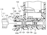
- the battery-type light source 103 is an exterior part, and an illumination lamp 121 and a battery (not shown) such as a dry battery or a storage battery that supplies power to the illumination lamp 121 are incorporated therein. .
- Reference numeral 120 shown in FIGS. 6B and 6C is an attachment portion and is provided in the battery-type light source 103.
- the mounting portion 120 is detachable from the connecting portion 110 of the endoscope 100, that is, can be attached and detached.
- Reference numeral 122 denotes a lamp storage unit in which the illumination lamp 121 is stored.
- Reference numeral 123 denotes a battery storage unit in which a battery (not shown) that supplies power to the illumination lamp 121 is stored.
- the mounting portion 120 is mainly provided with a pipe-shaped mounting portion main body 124 in which the light guide base 112 is inserted and disposed, and a cylindrical female threaded portion 125 that is screwed into the male threaded portion 113 on the inner peripheral surface.
- An attachment ring 126 and a connection base 128 on which the attachment ring 126 is rotatably arranged are provided.
- Numeral 126h is a vent hole, which is a through hole that passes through the outer periphery of the attachment ring 126 and the ring internal space 127 of the attachment ring 126.
- a plurality of vent holes 126 h are arranged in the circumferential direction of the mounting ring 126.
- the ring internal space 127 is a space that can be a second chamber.
- connection base 128 is fixed at a predetermined position on the front end side of the lamp housing tube 129.
- the illumination lamp 121 is disposed in the lamp housing hole 130 of the lamp housing tube 129.
- Reference numeral 131 denotes a lamp contact portion.
- the illumination lamp 121 is connected in contact with the lamp contact portion 131 and is disposed in the lamp storage space 129 ⁇ / b> S serving as a first chamber located on the distal end side of the contact portion 131.
- the lamp housing cylinder 129 is a heat transfer body, and an illumination lamp 121 that is a heat source is connected to a lamp contact portion 131 provided on the first end side.
- the connection cap 128 is a heat radiating body and is connected to the other end of the lamp housing cylinder 129 that is the second end.
- symbol 132 of FIG. 6B is a power switch.
- the user attaches the attachment part 120 of the battery-type light source 103 to the connection part 110 of the operation part 102. That is, the female screw part 125 of the attachment ring 126 is screwed into the male screw part 113 provided on the connection base 111 of the connection part 110. Then, as shown in FIG. 6D, the battery-type light source 103 is integrally fixed and disposed on the operation unit 102, the light guide base 112 is engaged and disposed in the attachment main body 124, and the connection base 111 is in the ring internal space 127. Placed inside. As a result, the opening on the front end side of the ring inner space 127 is closed by the connection cap 111 or the like, and the ring inner space 127 is configured as the second chamber.
- the user operates the power switch 132 to turn it on.
- the illumination lamp 121 is turned on, illumination light is supplied to the light incident end of the light guide fiber, is transmitted through the light guide fiber, and is irradiated onto the observation site from the illumination window.
- the heat generated from the illumination lamp 121 is conducted from the lamp contact portion 131 to the lamp housing tube 129.
- the connection cap 128 disposed in the second chamber is always exposed to the outside air because the second chamber communicates with the outside through the vent hole 126h. Therefore, the heat conducted to the storage cylinder 129 is then conducted to the connection cap 128 and radiated.
- the illumination lamp 121 serving as a heat source is provided inside the battery-type light source 103 attached to the operation unit 102
- the illumination lamp 121 is connected to the lamp contact portion 131 of the lamp housing cylinder 129, and the lamp housing cylinder is connected.
- the base end portion of 129 is placed in close contact with the connection base 128 arranged in the second chamber. Then, the second chamber is communicated with the outside through the vent hole 126h.
- connection base 128 arranged in the second chamber is always exposed to the outside air, the heat generated from the illumination lamp 121 is not trapped in the lamp storage cylinder 129, and the connection base 128 is removed from the lamp storage cylinder 129. It is conducted and is dissipated.
- the heat generated from the illumination lamp 121 is conducted to the exterior parts such as the lamp housing part 122 and the battery housing part 123 of the battery-type light source 103, and the occurrence of a problem that the surface temperature rises to a high temperature can be prevented.
- the operation unit 102 can be prevented from being heated.
- the temperature rise of the heat source provided in the sealed space is suppressed, and the surface temperature of the operation unit held by the hand or the surface temperature of the battery housing unit is prevented from becoming high, and the operability is excellent.
- An endoscope can be realized.
Landscapes
- Physics & Mathematics (AREA)
- Health & Medical Sciences (AREA)
- Life Sciences & Earth Sciences (AREA)
- Surgery (AREA)
- Optics & Photonics (AREA)
- Biomedical Technology (AREA)
- Medical Informatics (AREA)
- Nuclear Medicine, Radiotherapy & Molecular Imaging (AREA)
- Pathology (AREA)
- Radiology & Medical Imaging (AREA)
- Astronomy & Astrophysics (AREA)
- Engineering & Computer Science (AREA)
- General Physics & Mathematics (AREA)
- Biophysics (AREA)
- Molecular Biology (AREA)
- Heart & Thoracic Surgery (AREA)
- Animal Behavior & Ethology (AREA)
- General Health & Medical Sciences (AREA)
- Public Health (AREA)
- Veterinary Medicine (AREA)
- Endoscopes (AREA)
- Instruments For Viewing The Inside Of Hollow Bodies (AREA)
Abstract
内視鏡1は、操作部3と、密閉空間である本体空間8Sを有し、手で把持するのに適した操作部本体8と、操作部本体8の本体空間8Sに配設される熱源10と、熱源10から発する熱を伝導によって集めたヒートシンク30と、ヒートシンク30を覆い囲む被覆空間9S、および、被覆空間9S内と外部とを連絡する通気孔9hを有するカバー部9と、を具備する。
Description
本発明は、熱源を操作部の空間部またはその近傍の空間部に設けた内視鏡に関する。
近年、内視鏡は、医療分野及び工業用分野等において利用されている。
医療分野において用いられる内視鏡は、挿入部を被検体である体内に挿入することによって、体内の観察等を行うことができるようになっている。内視鏡には挿入部と操作部とを一体にした構成、あるいは、挿入部と操作部とを分離可能にした構成、がある。また、挿入部には、硬性なタイプと、軟性なタイプと、がある。また、挿入部に撮像部を配設した内視鏡、操作部に撮像部を配設した内視鏡がある。
一方、工業用分野において用いられる内視鏡は、軟性な挿入部を被検体であるジェットエンジン内、工場の配管内等に挿入して、傷の有無、或いは、腐蝕の有無等の検査を行うことができるようになっている。
挿入部の先端部に設けられた撮像素子と例えばビデオプロセッサとを結ぶ伝送路が長距離である内視鏡においては、画質の向上を図るため、操作部内に撮像素子の信号を増幅させる中継基板を設けたものがある。この構成によれば、信号ケーブルの細径化を実現しつつ画質の向上を図れる(日本国特開2009-279148号公報)。
また、医療分野及び工業用分野に関わらず、内視鏡には、充電式のバッテリを搭載したバッテリ駆動型の内視鏡が実現されている。バッテリ駆動型の内視鏡は持ち運びが容易であるとともに、電源の無い所での使用が可能になるので緊急時の使用などに好適である。
例えば、日本国特開2003-135395号公報には、電源に乾電池を用いたバッテリ型光源を内視鏡操作部に着脱自在に取り付けられるようにした内視鏡装置が示されている。
日本国特開2006-280542号公報には、バッテリの電力がCPUにより制御される電力供給部から、電子内視鏡の各部に供給される電子内視鏡が示されている。この電子内視鏡においては、先端部にLED光源を配する構成、及び先端部ではなく操作部の内部にLED光源を配してライトガイドで先端部に導光する構成が示されている。
しかしながら、中継基板等の基板、LED光源、および、照明ランプ等からは、熱が発せられる。一般に、内視鏡の操作部、および、バッテリ収容部は、密閉空間を有し、該密閉空間内に熱源が設けられる。外装部このため、内視鏡を長時間に渡って使用した場合、熱源から発せられる熱が密閉空間内の温度を上昇させて外装部操作部表面温度、あるいは、バッテリ収容部表面温度が上昇する。
そして、操作部の表面温度、或いは、バッテリ収容部の表面温度が高温になると、操作部把持性に悪影響を及ぼして操作性を低下させる要因に成り得る。
本発明は上記事情に鑑みてなされたものであり、密閉空間内に設けられた熱源の温度上昇を抑え手で把持される操作部の表面温度或いはバッテリ収容部の表面温度が高温になることを防止して操作性に優れた内視鏡を提供することを目的にしている。
本発明の一態様の内視鏡は、被検体に挿入される挿入部と、前記挿入部の基端側に設けられた操作部と、密閉空間である第一室を有し、手で把持するのに適した前記操作部を構成する第1の外装部と、前記第1外装部の第一室内に配設される熱源と、前記熱源から発する熱を伝導によって集めた熱集中部と、前記熱集中部を覆い囲む空間である第二室、および、該第二室内と外部とを連絡する連絡路を有する前記操作部を構成する第2の外装部と、を具備している。
以下、図面を参照して本発明の実施の形態を説明する。
なお、以下の説明に用いる各図面は、模式的に示すものであり、各構成要素を図面上で認識可能な程度に示すために、各部材の寸法関係や縮尺等は、各構成要素毎に縮尺を異ならせてあるものであり、本発明は、これらの図に記載された構成要素の数量、構成要素の形状、構成要素の大きさの比率、及び各構成要素の相対的な位置関係のみに限定されるものではない。
図1に示すように内視鏡1は、挿入部2と、この挿入部2の基端側に設けられた操作部3と、を備えて主に構成されている。
挿入部2は、先端側から順に硬性の先端部4と、例えば上下方向に湾曲自在な湾曲部5と、可撓性を有する可撓管部6と、を連設して構成されている。
挿入部2の先端部4内には撮像素子7が内蔵されており、先端面には観察窓(不図示)及び照明窓(不図示)が設けられている。
操作部3は、第一室を備える第1の外装部である例えば樹脂製の操作部本体8と、第二室を備える第2の外装部である例えば樹脂製のカバー部9と、を具備して構成されている。
操作部本体8は、ユーザーの手によって把持するのに適した形状に形作られた把持部を含み、湾曲部5を湾曲操作するための湾曲操作装置としての上下用ノブ8a、各種操作ボタン8b、8c等が設けられている。上下用ノブ8a、各種操作ボタン8b、8c等は、ユーザーの手指によって操作される。
操作部本体8は、第一室として密閉空間である本体空間8Sを備え、本体空間8S内には、熱源10、伝熱体であるヒートパイプ20、及び熱集中部となるヒートシンク30が配設されている。
熱源10は、電子部品を実装した基板、或いは、発光素子である例えばLED光源等である。ヒートパイプ20は、第1端と第2端とを有し、第1端である先端部21には熱源10が接続され、第2端である基端部22には例えば円板形状のヒートシンク30が接続されている。つまり、熱源10は、ヒートパイプ20を介してヒートシンク30に接続されている。なお、熱源10を直接ヒートシンク30に接続するようにしてもよい。
ヒートシンク30は、基端部22が接続される第1面31と、該第1面31の反対面である第2面32とを有する例えば円板形状である。第2面32側に表面積を増大させて冷却効果を高めるフィン部(不図示)を設けるようにしてよい。
操作部本体8の基端側の壁部の基端壁面8wには本体空間8Sと外部とを連絡する第1貫通孔8hが形成されている。第1貫通孔8hにはヒートシンク30の外周面が密着して水密を保持するように一体固定されている。
カバー部9は、例えばドーム形状であって、第二室として被覆空間9Sを備えている。カバー部9には、外部と被覆空間9Sとを連絡する連絡路として例えば貫通孔である2つ以上の通気孔9hが設けられている。
カバー部9の開口側端面9fは、操作部本体8の基端壁面8wの外側面8oに配置される。この配置状態において、被覆空間9S内にはヒートシンク30の第2面32が配置される。
この構成によれば、カバー部9によって操作部本体8を把持するユーザーの手指が基端壁面8wに露出されたヒートシンク30の第2面32に誤って触れてしまうことが防止される。また、通気孔9hによって外部と被覆空間9S内とが連通状態であるので、被覆空間9S内に配設されたヒートシンク30の第2面32は、通気孔9hから侵入するに外気に、常時、晒される。
なお、通気孔9hの孔径は、ユーザーの手指がヒートシンク30の第2面32に直接触れることを防止する寸法、すなわち、被覆空間9S内に侵入することを防止するように設定してある。
上述した内視鏡1によれば、熱源10から発生した熱の一部は、ヒートパイプ20の先端部21に伝導される。その後、ヒートパイプ20の先端部21に伝導された熱は、該先端部21から基端部22に伝導されていく。
そして、基端部22に移動された熱は、ヒートシンク30の第1面31側から吸熱され、第2面32側に伝熱されて放熱されるようになっている。第2面32は、外気に晒されているので熱が効率良く放熱される。
この結果、熱源10の温度上昇が抑制される。
このように、操作部3の操作部本体8内に熱源10を配設する構成において、熱源10をヒートパイプ20を介して、あるいは、直接通気孔9hによって外気に晒されている第2面32を有する操作部本体8に固設されたヒートシンク30に伝導する。
この結果、熱源10から発生する熱の一部がヒートパイプ20を介してヒートシンク30の第2面32から外部に放熱される。
したがって、熱源10の温度上昇が抑制されて熱源10から操作部本体8の本体空間8S内に放射される熱量が低下して操作部本体8の表面温度が高温に上昇する不具合の発生を防止できる。
なお、操作部本体8は、図示されていない複数の部材を組み付けて一体に固定して構成されている。
また、操作部本体8とカバー部9とは着脱自在に構成されており、図示されていない連結部材である例えば取付ネジによってカバー部9が操作部本体8に対して一体固定されるようになっている。したがって、取付ネジを取り外すことによって操作部本体8からカバー部9の取り外しを行った上で内視鏡1の洗浄消毒等を行える。
また、操作部本体8の外周面に雄ねじ部を設け、カバー部9の内周面に雌ねじ部を設ける構成、あるいは、その逆の構成にして操作部本体8とカバー部9とを着脱自在な構成にするようにしてもよい。
図2を参照して操作部の他の構成例を説明する。
図2に示すように操作部3Aは、操作部本体8Aと、カバー部9Aと、を具備して構成されている。
操作部本体8Aの本体空間8S内には、熱源10、ヒートパイプ20、及びヒートシンク30が配設されている。本実施形態において、ヒートシンク30の第2面32が基端壁面8wの内面壁8iに取付固定されている。すなわち、操作部本体8Aは、第1貫通孔8hを不要としている。
一方、カバー部9Aの構成は上述した実施形態と略同様であって、通気孔9hの代わりに複数の切欠9cを開口側端面9fに設けている。
この構成とすることで、カバー部9を操作部本体8に装着することにより切り欠き9cが通気孔9hと同様の役割を果たす。
その他の構成は上述した実施形態と同様で有り、同部材には同符号を付して説明を省略する。
本実施形態において、カバー部9Aの開口側端面9fは、操作部本体8Aの基端壁面8wの外側面8oに配置される。この結果、被覆空間9S内に基端壁面8wの外側面8oが配置される。
この構成によれば、基端壁面8wの外側面8oが切欠9cから侵入するに外気に、常時、晒されて温度が低くされる。
この結果、熱源10から発生した熱の一部は、ヒートパイプ20を介して、あるいは、直接ヒートシンク30に伝導され、その後、ヒートシンク30の第2面32から内面壁8iの界面を介して基端壁面8wに伝導される。
伝導された熱は、基端壁面8wの外側面8oが外気に晒されていることによって、基端壁面8wから放熱されて、熱源10の温度上昇が抑制される。
したがって、上述した実施形態と同様の作用及び効果を得ることができる。
図3を参照して操作部の別の構成例を説明する。
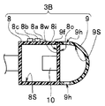
図3に示すように操作部3Bは、操作部本体8と、例えばカバー部9と、を具備して構成されている。そして、操作部本体8の本体空間8S内には熱源10が配設され、その熱源10が直接基端壁面8wの内面壁8iに取付固定されている。
その他の構成は上述した図1に示した実施形態と同様で有り、同部材には同符号を付して説明を省略する。
本実施形態においては、カバー部9の開口側端面9fを操作部本体8の基端壁面8wの外側面8oに配置することにより、被覆空間9S内に基端壁面8wの外側面8oが配置される。
この構成によれば、熱源10から発生した熱の一部は、直接熱源10から内面壁8iの界面を介して基端壁面8wに伝導される。伝導された熱は、基端壁面8wの外側面8oが外気に晒されていることによって、基端壁面8wから放熱されて、熱源10の温度上昇が抑制されて、上述した実施形態と同様の作用及び効果を得ることができる。
図4を参照して操作部の別の構成例を説明する。
図4に示すように操作部3Cは、操作部本体8Cと、例えばカバー部9と、を具備して構成されている。本実施形態において、操作部本体8Cの本体空間8S内には、熱源10及びヒートパイプ20が配設されている。
基端壁面8wには第2の貫通孔であるパイプ孔8pが設けられている。
パイプ孔8pは、本体空間8Sと外部とを連絡し、パイプ孔8pにはヒートパイプ20の外周面が密着して水密を保持するように一体固定されている。
この構成によれば、ヒートパイプ20の基端部22側が基端壁面8wの外側面8oから突出させること、および、ヒートシンク30を基端壁面8wの外側面8oより外側に配置させることができる。
カバー部9の構成は、上述した実施形態と略同様であり、カバー部9の開口側端面9fを操作部本体8Cの基端壁面8wの外側面8oに配置することにより、被覆空間9S内にはヒートシンク30およびヒートパイプ20の基端部22側が配置される。
その他の構成は上述した実施形態と同様で有り、同部材には同符号を付して説明を省略する。
この構成によれば、基端壁面8wの外側面8oより突出したヒートパイプ20の基端部22側及びヒートシンク30が通気孔9hから侵入するに外気に、常時、晒される。
この結果、熱源10から発生した熱の一部は、ヒートパイプ20を介してヒートシンク30に伝導されつつ、外気に常時晒されたヒートパイプ20の基端部22及びヒートシンク30から放熱されて、熱源10の温度上昇が抑制される。
したがって、上述した実施形態と同様の作用及び効果を得ることができる。
ここで、図5A、図5Bを参照して内視鏡の他の構成例を説明する。
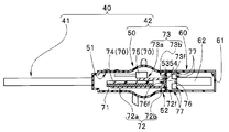
本実施形態の内視鏡は、例えば携帯型の内視鏡であって、図5Aに示すように内視鏡40は、挿入部41と、操作部42と、を備えて主に構成されている。
挿入部41は、先端側から順に硬性の先端部43と、例えば上下方向に湾曲自在な湾曲部44と、可撓性を有する可撓管部45と、を連設して構成されている。
挿入部41の先端部43内には撮像素子(不図示)が内蔵されており、先端面には観察窓(不図示)及び照明窓(不図示)が設けられている。
操作部42は外装部であって、第一室を有する第1の外装部である操作部本体50と、第二室を有する第2の外装部であるカバー部60と、で構成されている。カバー部60は、操作部本体50に対して着脱自在なバッテリーケースを兼用する。
図5Bに示すように操作部本体50は、第一室として本体空間51を備え、本体空間51内には、熱源70、吸熱用ヒートシンク71及び伝熱体であるヒートパイプ72、73が配設されている。
熱源70は、電子部品を実装した基板74、或いは、発光素子である例えばLED光源75等であり、内視鏡観察中、基板74及びLED光源75からは熱が発せられる。
吸熱用ヒートシンク71は、基板74の熱を吸熱する吸熱体であって、第1ヒートパイプ72が対面する基板74の一面側には吸熱用ヒートシンク71が一体的に接続されている。
第1ヒートパイプ72は、第1端と第2端とを有し、第1端である先端部72aが吸熱用ヒートシンク71の一面の反対面である他面に接続されている。第2ヒートパイプ73は、第1端と第2端とを有し、第1端である先端部73aがLED光源75に接続されている。
一方、ヒートパイプ72、73のパイプ基端部72b、73bは、操作部本体50の基端部52に配置されている。本実施形態においては、第1ヒートパイプ72のパイプ基端部72bと、第2ヒートパイプ73のパイプ基端部73bとは一体である。
上述した配置状態において、パイプ基端部72b、73bの基端面72f、73fと、基端部52の表面とが同一平面、すなわち、面一致に配置される。
一方、カバー部60は、第二室であるカバー部内部空間61内にバッテリーセル62が配設される。バッテリーセル62は、基板74に実装された電子部品、及び、LED光源75に電力を供給する給電部である。
操作部本体50の基端側壁53には放熱用ヒートシンク76が設けられている。放熱用ヒートシンク76の一面は、当接面76fである。当接面76fには、第1ヒートパイプ72のパイプ基端部72bの基端面72f及び第2ヒートパイプ73のパイプ基端部73bの基端面73fがそれぞれ当接している。
なお、当接面76fの反対面は、放熱面であって、複数のフィンが設けられている。放熱用ヒートシンク76の側面は、操作部本体50の基端壁面53に設けられた貫通孔55に水密を保持するように一体固定されている。
また、カバー部60の先端側の外周面には、外部とカバー部内部空間61とを通じる貫通孔である複数の通気孔77が周方向に配列されている。
本実施形態において、カバー部60には例えば雌ねじ部を有する固定リング(不図示)が回動自在に設けられ、操作部本体50の基端側外周面には雄ねじ部が設けられている。
固定リングの雌ねじ部を雄ねじ部に螺合していくことによって、カバー部60と操作部本体50とが一体に固設されて操作部42が構成される。このとき、放熱用ヒートシンク76の放熱面は、カバー部60によって覆われる。
この構成によれば、外部とカバー部内部空間61内とが通気孔77によって常時連通される。したがって、カバー部内部空間61内に設けられている放熱用ヒートシンク76は、通気孔77から侵入するに外気に、常時、晒された状態になる。
したがって、基板74から発生する熱は、吸熱用ヒートシンク71に吸熱された後、第1ヒートパイプ72の先端部72aに伝導され、その後、基端部72bに移動していく。
一方、LED光源75から発生する熱は、第2ヒートパイプ73の先端部73aに伝導され、その後、基端部73bに移動していく。
このように、操作部42の操作部本体50内に熱源70を配設する構成において、熱源70にヒートパイプ72、73の先端部72a、73aを接続し、基端部72b、73bを放熱用ヒートシンク76に密着配置させる。そして、放熱用ヒートシンク76の基端側部分を通気孔77を有するカバー部60のカバー部内部空間61内には配設する。
この結果、熱源70から発生する熱の一部は、ヒートパイプ72、73の先端部72a、73aに伝導され、その後、常に、外気に晒されて温度が低い放熱用ヒートシンク76に密着配置された基端部72b、73bに移動され、その後放熱用ヒートシンク76に吸熱されて該ヒートシンク76から放熱される。
したがって、熱源70の温度上昇が抑制されて熱源70から熱が操作部本体50の本体空間51内に放射される熱量が低下して操作部本体50の表面温度が高温に上昇する不具合の発生を防止できる。また、ヒートシンク70は、高温度となるが、ヒートシンク70の放熱面が固設されたカバー部60によって覆われていることにより、ユーザーの手指が高温部に触れることがない。
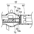
なお、第1ヒートパイプ72のパイプ基端部72bと第2ヒートパイプ73のパイプ基端部73bとが別体であってもよい。この構成において、放熱用ヒートシンク76の側面を操作部本体50の基端壁面53に設けられた貫通孔54に水密に固定する代わりに、図5Cに示すように第1ヒートパイプ72の基端部72bを操作部本体50の基端壁面53に設けられた第1貫通孔55に水密に固定し、第2ヒートパイプ73の基端部73bを操作部本体50の基端壁面53に設けられた第2貫通孔56に水密に固定してもよい。
また、ヒートパイプ72、73と放熱用ヒートシンク76とを一体に構成するようにしてもよい。この構成においては、一体に構成した基端部(不図示)を、操作部本体50の基端壁面53に設けられた貫通孔54に水密に固定する。
次に、図6A-図6Dを参照して内視鏡の別の構成例を説明する。
本実施形態の内視鏡は、バッテリ型光源が着脱自在な携帯型の内視鏡であって、図6Aに示すように内視鏡100は、挿入部101と、操作部102と、バッテリ型光源103と、を備えて主に構成されている。符号104は、接眼部である。
挿入部101は、先端側から順に硬性の先端部105と、例えば上下方向に湾曲自在な湾曲部106と、可撓性を有する可撓管部107と、を連設して構成されている。
挿入部101の先端部105の先端面には観察窓(不図示)及び照明窓(不図示)が設けられており、挿入部101内には観察像を接眼部104まで伝送するイメージガイドファイバ(不図示)及び照明光を伝送するライトガイドファイバ(不図示)が挿通配置されている。
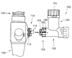
図6Bに示すようにバッテリ型光源103は、照明光供給部であって、操作部102の側部に設けられた連結部110に対して着脱自在である。連結部110には連結口金111及びライトガイド口金112が設けられており、連結口金111の外周部には雄ねじ部113が設けられている。
なお、ライトガイドファイバの一端部は、ライトガイド口金112内に配設され、他端部は照明窓に臨まれている。
図6Cに示すようにバッテリ型光源103は、外装部であって、その内部には照明ランプ121及びこの照明ランプ121に電源を供給する例えば乾電池又は蓄電池などの電池(不図示)が内蔵される。
図6B、図6Cに示す符号120は、取付部であってバッテリ型光源103に設けられている。
取付部120は、内視鏡100の連結部110に対して着脱自在、すなわち、取り付け、取り外し自在である。符号122は、ランプ収納部であって照明ランプ121が収納される。符号123は、電池収納部であって照明ランプ121に電源を供給する電池(不図示)が収納される。
取付部120には、主に、パイプ形状で、ライトガイド口金112が係入配置される取付け部本体124と、筒状で、雄ねじ部113に螺合する雌ねじ部125を内周面に設けた取付環126と、取り付け環126が回動自在に配設される接続口金128と、が設けられている。
符号126hは、通気孔であって、取付環126の外周外方と、取付環126の環内部空間127と、を通じる貫通孔である。通気孔126hは、取付環126の周方向に複数配列されている。環内部空間127は、第二室と成り得る空間である。
接続口金128は、ランプ収納筒129の先端側の予め定めた位置に固定されている。照明ランプ121は、ランプ収納筒129のランプ収納穴130内に配設される。符号131は、ランプ当接部である。照明ランプ121は、ランプ当接部131に当接して接続され、該当接部131より先端側に位置する第一室となるランプ収納空間129Sに配置される。
本実施形態において、ランプ収納筒129は、伝熱体であって、第1端側に設けられたランプ当接部131に熱源である照明ランプ121が接続される。また、接続口金128は、放熱体であって、ランプ収納筒129の第2端である他端側端部に接続されている。
なお、図6Bの符号132は、電源スイッチである。
上述した内視鏡100の作用を説明する。
内視鏡100を使用する際、ユーザーは、操作部102の連結部110にバッテリ型光源103の取付部120を取り付ける。すなわち、連結部110の連結口金111に設けられた雄ねじ部113に取付環126の雌ねじ部125を螺合していく。すると、図6Dに示すように操作部102にバッテリ型光源103が一体的に固定配置されて、ライトガイド口金112が取付部本体124に係入配置されると共に、連結口金111が環内部空間127内に配置される。この結果、環内部空間127の先端側の開口が連結口金111等によって塞がれて、環内部空間127が第二室として構成される。
次に、ユーザーは、電源スイッチ132を操作してオン状態にする。すると、照明ランプ121が点灯し、照明光がライトガイドファイバの光入射端に供給され、該ライトガイドファイバを伝送されて照明窓から観察部位に照射される。
照明ランプ121から発生する熱は、ランプ当接部131からランプ収納筒129に伝導されていく。第二室に配置されている接続口金128は、第二室と外部とが通気孔126hを介して通じているため常に、外気に晒されている。したがって、収納筒129に伝導された熱は、その後、接続口金128に伝導されて放熱されていく。
このように、操作部102に取り付けられるバッテリ型光源103の内部に熱源となる照明ランプ121を設けた構成において、照明ランプ121をランプ収納筒129のランプ当接部131に接続し、ランプ収納筒129の基端部を第二室に配置されている接続口金128に密着配置させる。そして、第二室を通気孔126hを介して外部と連通させる。
この結果、第二室に配置された接続口金128が、常に、外気に晒されるため、照明ランプ121から発生する熱が、ランプ収納筒129内にこもること無く、ランプ収納筒129から接続口金128に伝導されて放熱されていく。
したがって、照明ランプ121から発生する熱がバッテリ型光源103のランプ収納部122、電池収納部123等の外装部に伝導されてその表面温度が高温に上昇する不具合の発生を防止することができるとともに、操作部102が加熱されることを防止できる。
尚、本発明は、以上述べた実施形態のみに限定されるものではなく、発明の要旨を逸脱しない範囲で種々変形実施可能である。
また、上述した実施形態は、挿入部と操作部とを一体に構成した内視鏡を有する内視鏡装置について述べたが、挿入部と操作部とが分離可能であり、熱源である撮像素子が操作部内に配置された内視鏡を有する実施形態においても採用できる。
本発明によれば、密閉空間内に設けられた熱源の温度上昇を抑え手で把持される操作部の表面温度或いはバッテリ収容部の表面温度が高温になることを防止して操作性に優れた内視鏡を実現できる。
本出願は、2015年4月24日に日本国に出願された特願2015-089706号を優先権主張の基礎として出願するものであり、上記の開示内容は、本願明細書、請求の範囲に引用されるものとする。
Claims (10)
- ユーザーによって把持するのに適した把持部を有する操作部と、
密閉空間である第一室を有し、手で把持するのに適した前記操作部を構成する第1の外装部と、
前記第1の外装部の前記第一室内に配設される熱源と、
前記熱源から発する熱を伝導によって集めた熱集中部と、
前記熱集中部を覆い囲む空間である第二室、および、該第二室内と外部とを連絡する連絡路を有する前記操作部を構成する第2の外装部と、
を具備することを特徴とする内視鏡。 - 前記熱集中部は、第1面と該第1面の反対面である第2面とを有する放熱体であって、
前記放熱体の前記第1面には、前記熱源が直接、または、該熱源が第1端と第2端とを有する伝熱体を介して接続される
ことを特徴とする請求項1に記載の内視鏡。 - 前記放熱体を前記第1の外装部の壁部に設けられた前記第一室と前記外部とを連絡する第1の貫通孔に水密に固設して該第1の外装部の壁部に該放熱体の前記第2面を露出させ、露出した該第2面を前記第2の外装部の前記第二室内に配置することを特徴とする請求項2に記載の内視鏡。
- 前記第2の外装部の前記第二室内に前記第1の外装部の壁部の外側面を配置する構成において、
前記放熱体の前記第2面を該第1の外装部の壁部の内面壁に取付固定して、該放熱体に集められた熱をさらに当該第1の外装部の壁部に伝導することを特徴とする請求項2に記載の内視鏡。 - 前記第2の外装部の前記第二室内に前記第1の外装部の壁部の外側面を配置する構成において、
前記熱源を該第1の外装部の壁部の内面壁に取付固定して、該熱源から発する熱を伝導によって当該第1の外装部の壁部に伝導することを特徴とする請求項1に記載の内視鏡。 - 前記伝熱体を、前記第1の外装部の壁部に設けられた前記第一室と前記外部とを連絡する第2の貫通孔に水密に固設する構成において、
前記放熱体を前記第1の外装部の壁部の外側に配設して少なくとも該放熱体を前記第2の外装部の前記第二室内に配置することを特徴とする請求項2に記載の内視鏡。 - 前記第二室内と前記外部とを連絡する前記連絡路は、通気孔、または、切欠であって、該通気孔、または、該切欠の大きさは手指が前記第二室内に侵入することを防止することを特徴とする請求項1に記載の内視鏡。
- 前記第2の外装部は、前記第1の外装部に着脱自在であることを特徴とする請求項2-7の何れか1項に記載の内視鏡。
- 前記切欠は、前記第2の外装部の開口側端面側に設けられ、前記第2の外装部を前記第1の外装部に装着することによって該切欠が前記連絡路として構成されることを特徴とする請求項7に記載の内視鏡。
- 前記通気孔は、2つ以上であることを特徴とする請求項7に記載の内視鏡。
Applications Claiming Priority (2)
| Application Number | Priority Date | Filing Date | Title |
|---|---|---|---|
| JP2015-089706 | 2015-04-24 | ||
| JP2015089706 | 2015-04-24 |
Publications (1)
| Publication Number | Publication Date |
|---|---|
| WO2016170941A1 true WO2016170941A1 (ja) | 2016-10-27 |
Family
ID=57143582
Family Applications (1)
| Application Number | Title | Priority Date | Filing Date |
|---|---|---|---|
| PCT/JP2016/060422 Ceased WO2016170941A1 (ja) | 2015-04-24 | 2016-03-30 | 内視鏡 |
Country Status (1)
| Country | Link |
|---|---|
| WO (1) | WO2016170941A1 (ja) |
Cited By (1)
| Publication number | Priority date | Publication date | Assignee | Title |
|---|---|---|---|---|
| JP2023516652A (ja) * | 2020-03-05 | 2023-04-20 | エヌエスブイ、インコーポレイテッド | ビジョンセンサ装置 |
Citations (6)
| Publication number | Priority date | Publication date | Assignee | Title |
|---|---|---|---|---|
| JPH1043133A (ja) * | 1996-08-02 | 1998-02-17 | Olympus Optical Co Ltd | 内視鏡 |
| JPH11206707A (ja) * | 1998-01-20 | 1999-08-03 | Asahi Optical Co Ltd | 簡易型内視鏡装置 |
| JP2000056239A (ja) * | 1998-08-07 | 2000-02-25 | Olympus Optical Co Ltd | 内視鏡装置 |
| JP2003310547A (ja) * | 2002-02-25 | 2003-11-05 | Olympus Optical Co Ltd | 内視鏡装置 |
| JP2011036365A (ja) * | 2009-08-10 | 2011-02-24 | Olympus Corp | 内視鏡装置 |
| US20140206939A1 (en) * | 2013-01-22 | 2014-07-24 | Karl Storz Gmbh & Co. Kg | Endoscopic and/or medical device and cooling device for an endoscope or a medical instrument |
-
2016
- 2016-03-30 WO PCT/JP2016/060422 patent/WO2016170941A1/ja not_active Ceased
Patent Citations (6)
| Publication number | Priority date | Publication date | Assignee | Title |
|---|---|---|---|---|
| JPH1043133A (ja) * | 1996-08-02 | 1998-02-17 | Olympus Optical Co Ltd | 内視鏡 |
| JPH11206707A (ja) * | 1998-01-20 | 1999-08-03 | Asahi Optical Co Ltd | 簡易型内視鏡装置 |
| JP2000056239A (ja) * | 1998-08-07 | 2000-02-25 | Olympus Optical Co Ltd | 内視鏡装置 |
| JP2003310547A (ja) * | 2002-02-25 | 2003-11-05 | Olympus Optical Co Ltd | 内視鏡装置 |
| JP2011036365A (ja) * | 2009-08-10 | 2011-02-24 | Olympus Corp | 内視鏡装置 |
| US20140206939A1 (en) * | 2013-01-22 | 2014-07-24 | Karl Storz Gmbh & Co. Kg | Endoscopic and/or medical device and cooling device for an endoscope or a medical instrument |
Cited By (1)
| Publication number | Priority date | Publication date | Assignee | Title |
|---|---|---|---|---|
| JP2023516652A (ja) * | 2020-03-05 | 2023-04-20 | エヌエスブイ、インコーポレイテッド | ビジョンセンサ装置 |
Similar Documents
| Publication | Publication Date | Title |
|---|---|---|
| JP5443677B2 (ja) | 照明装置および内視鏡 | |
| JP5178239B2 (ja) | 医療用システム | |
| JP5139742B2 (ja) | 内視鏡 | |
| CN101099662B (zh) | 内窥镜 | |
| CN103037749B (zh) | 内窥镜 | |
| US8801255B2 (en) | Endoscope | |
| JP5389731B2 (ja) | 内視鏡 | |
| JP5341279B2 (ja) | 内視鏡装置 | |
| US20190183324A1 (en) | Digital disposable endoscope system | |
| JP5642904B2 (ja) | 内視鏡 | |
| WO2020121435A1 (ja) | 内視鏡の先端部および内視鏡 | |
| JP2005027851A (ja) | 内視鏡 | |
| JP5231071B2 (ja) | 内視鏡装置、アダプタ | |
| US11744449B2 (en) | Endoscopy system | |
| WO2016170941A1 (ja) | 内視鏡 | |
| JP6210764B2 (ja) | 電子内視鏡 | |
| JP5174330B2 (ja) | 内視鏡 | |
| CN223158365U (zh) | 腹腔镜摄像手柄结构 | |
| US20230414087A1 (en) | Insertion instrument | |
| JP2003169777A (ja) | 内視鏡用バッテリ型光源装置 | |
| JP2009022588A (ja) | 照明装置、及びこの照明装置を備えた内視鏡 | |
| JP5836189B2 (ja) | 内視鏡用撮像モジュール及び電子内視鏡装置 | |
| JP2007244904A (ja) | 内視鏡 | |
| JP5509003B2 (ja) | 内視鏡 | |
| JP5356049B2 (ja) | 内視鏡 |
Legal Events
| Date | Code | Title | Description |
|---|---|---|---|
| 121 | Ep: the epo has been informed by wipo that ep was designated in this application |
Ref document number: 16782963 Country of ref document: EP Kind code of ref document: A1 |
|
| NENP | Non-entry into the national phase |
Ref country code: DE |
|
| NENP | Non-entry into the national phase |
Ref country code: JP |
|
| 122 | Ep: pct application non-entry in european phase |
Ref document number: 16782963 Country of ref document: EP Kind code of ref document: A1 |