WO2016166858A1 - 顕微鏡観察システム、顕微鏡観察方法、及び顕微鏡観察プログラム - Google Patents
顕微鏡観察システム、顕微鏡観察方法、及び顕微鏡観察プログラム Download PDFInfo
- Publication number
- WO2016166858A1 WO2016166858A1 PCT/JP2015/061640 JP2015061640W WO2016166858A1 WO 2016166858 A1 WO2016166858 A1 WO 2016166858A1 JP 2015061640 W JP2015061640 W JP 2015061640W WO 2016166858 A1 WO2016166858 A1 WO 2016166858A1
- Authority
- WO
- WIPO (PCT)
- Prior art keywords
- image
- slice
- images
- omnifocal
- unit
- Prior art date
- Legal status (The legal status is an assumption and is not a legal conclusion. Google has not performed a legal analysis and makes no representation as to the accuracy of the status listed.)
- Ceased
Links
Images









Classifications
-
- G—PHYSICS
- G02—OPTICS
- G02B—OPTICAL ELEMENTS, SYSTEMS OR APPARATUS
- G02B21/00—Microscopes
- G02B21/36—Microscopes arranged for photographic purposes or projection purposes or digital imaging or video purposes including associated control and data processing arrangements
- G02B21/365—Control or image processing arrangements for digital or video microscopes
- G02B21/367—Control or image processing arrangements for digital or video microscopes providing an output produced by processing a plurality of individual source images, e.g. image tiling, montage, composite images, depth sectioning, image comparison
-
- G—PHYSICS
- G02—OPTICS
- G02B—OPTICAL ELEMENTS, SYSTEMS OR APPARATUS
- G02B21/00—Microscopes
- G02B21/36—Microscopes arranged for photographic purposes or projection purposes or digital imaging or video purposes including associated control and data processing arrangements
-
- G—PHYSICS
- G06—COMPUTING OR CALCULATING; COUNTING
- G06T—IMAGE DATA PROCESSING OR GENERATION, IN GENERAL
- G06T5/00—Image enhancement or restoration
- G06T5/50—Image enhancement or restoration using two or more images, e.g. averaging or subtraction
-
- G—PHYSICS
- G06—COMPUTING OR CALCULATING; COUNTING
- G06T—IMAGE DATA PROCESSING OR GENERATION, IN GENERAL
- G06T5/00—Image enhancement or restoration
- G06T5/73—Deblurring; Sharpening
-
- H—ELECTRICITY
- H04—ELECTRIC COMMUNICATION TECHNIQUE
- H04N—PICTORIAL COMMUNICATION, e.g. TELEVISION
- H04N23/00—Cameras or camera modules comprising electronic image sensors; Control thereof
- H04N23/95—Computational photography systems, e.g. light-field imaging systems
- H04N23/958—Computational photography systems, e.g. light-field imaging systems for extended depth of field imaging
-
- G—PHYSICS
- G02—OPTICS
- G02B—OPTICAL ELEMENTS, SYSTEMS OR APPARATUS
- G02B21/00—Microscopes
- G02B21/02—Objectives
- G02B21/025—Objectives with variable magnification
-
- G—PHYSICS
- G02—OPTICS
- G02B—OPTICAL ELEMENTS, SYSTEMS OR APPARATUS
- G02B21/00—Microscopes
- G02B21/06—Means for illuminating specimens
- G02B21/08—Condensers
- G02B21/088—Condensers for both incident illumination and transillumination
-
- G—PHYSICS
- G02—OPTICS
- G02B—OPTICAL ELEMENTS, SYSTEMS OR APPARATUS
- G02B21/00—Microscopes
- G02B21/24—Base structure
- G02B21/26—Stages; Adjusting means therefor
-
- G—PHYSICS
- G03—PHOTOGRAPHY; CINEMATOGRAPHY; ANALOGOUS TECHNIQUES USING WAVES OTHER THAN OPTICAL WAVES; ELECTROGRAPHY; HOLOGRAPHY
- G03B—APPARATUS OR ARRANGEMENTS FOR TAKING PHOTOGRAPHS OR FOR PROJECTING OR VIEWING THEM; APPARATUS OR ARRANGEMENTS EMPLOYING ANALOGOUS TECHNIQUES USING WAVES OTHER THAN OPTICAL WAVES; ACCESSORIES THEREFOR
- G03B15/00—Special procedures for taking photographs; Apparatus therefor
-
- G—PHYSICS
- G06—COMPUTING OR CALCULATING; COUNTING
- G06T—IMAGE DATA PROCESSING OR GENERATION, IN GENERAL
- G06T2207/00—Indexing scheme for image analysis or image enhancement
- G06T2207/10—Image acquisition modality
- G06T2207/10056—Microscopic image
-
- G—PHYSICS
- G06—COMPUTING OR CALCULATING; COUNTING
- G06T—IMAGE DATA PROCESSING OR GENERATION, IN GENERAL
- G06T2207/00—Indexing scheme for image analysis or image enhancement
- G06T2207/10—Image acquisition modality
- G06T2207/10141—Special mode during image acquisition
- G06T2207/10148—Varying focus
-
- G—PHYSICS
- G06—COMPUTING OR CALCULATING; COUNTING
- G06T—IMAGE DATA PROCESSING OR GENERATION, IN GENERAL
- G06T2207/00—Indexing scheme for image analysis or image enhancement
- G06T2207/20—Special algorithmic details
- G06T2207/20212—Image combination
- G06T2207/20221—Image fusion; Image merging
Definitions
- the present invention relates to a microscope observation system, a microscope observation method, and a microscope observation program for observing a subject through an image acquired in a microscope apparatus.
- a multifocal image generated by superimposing a Z stack image is restored using a blur function, or a focused region is extracted from each of a plurality of images having different focal planes.
- each image having a different focal plane is also referred to as a slice image.
- Patent Document 1 calculates the degree of focus in each slice image, selects a candidate area to be synthesized based on this degree of focus, and weights the candidate area according to the degree of focus. And a technique for synthesizing them.
- the user can instantly grasp the position of the structure in the subject in the Z direction on the two-dimensional XY plane.
- Patent Document 2 a user selects an area through a user interface for an omnifocal image generated from a Z stack image, and the area is focused on A technique for displaying a slice image is disclosed.
- a transparent subject such as a living body may have a plurality of focused structures in the Z direction, it is difficult to grasp the position of the structure in the Z direction from the omnifocal image.
- a plurality of structures are overlapped in the Z direction, it is also difficult to grasp the front-rear relationship between the structures, that is, the positional relationship in the Z direction.
- Patent Document 2 since a slice image having the highest degree of focus is extracted with respect to the region selected from the omnifocal image, when a plurality of structures with different Z positions overlap on the plane, The area selected by the user is not necessarily extracted.
- the present invention has been made in view of the above, and even when observing an omnifocal image of a transparent subject such as a living body, the user visually determines the position of the structure in the Z direction and the front-rear relationship between the structures. It is another object of the present invention to provide a microscope observation system, a microscope observation method, and a microscope observation program that can be intuitively grasped.
- the microscope observation system is generated by capturing a subject image while shifting the focal position along the optical axis of the observation optical system included in the microscope.
- An image acquisition unit that acquires a plurality of slice images, and an image that relatively shifts another slice image with respect to one slice image of the plurality of slice images in a plane including the one slice image
- the shift processing unit, the one slice image, and the other slice image shifted relative to the one slice image have different shift amounts of the other slice image with respect to the one slice image.
- An omnifocal image generation unit that generates a plurality of omnifocal images by combining under a plurality of conditions, and a display unit that displays the plurality of omnifocal images. It is characterized in.
- the microscope observation system includes an input unit that inputs information according to an operation performed from the outside, and a shift amount acquisition processing unit that calculates the shift amount in each of the plurality of conditions according to the information input from the input unit
- the image shift processing unit shifts the other slice image according to the shift amount calculated by the shift amount acquisition processing unit.
- the microscope observation system includes an observation region determination processing unit that determines, as an observation region, a region selected from any one of the plurality of omnifocal images according to an operation performed from the outside, and the observation region The region corresponding to the observation region is extracted from the omnifocal image other than the selected omnifocal image, and the position of the observation region in the omnifocal image from which the observation region is selected and the total region from which the region is extracted.
- An attention image extraction processing unit that extracts a slice image including the observation region from the plurality of slice images based on a shift amount with respect to a position of the region in the focus image.
- the omnifocal image generation unit is configured to be relative to the one slice image and the one slice image based on the position of the observation region in the omnifocal image where the observation region is selected.
- a cutout range determination processing unit that determines a range to be used when generating each of the plurality of omnifocal images with respect to the other slice image that has been shifted to is further provided.
- the microscope observation method includes an image acquisition step of acquiring a plurality of slice images generated by capturing a subject image while shifting a focal position along an optical axis of an observation optical system included in the microscope, An image shift processing step of shifting another slice image relative to one of the slice images in a plane including the slice image, the slice image, By synthesizing the other slice image shifted relative to the slice image under a plurality of conditions with different shift amounts of the other slice image with respect to the one slice image, And an omnifocal image generating step for generating a focal image, and a display step for displaying the plurality of omnifocal images.
- the microscope observation program includes a plurality of slice images for a plurality of slice images generated by capturing a subject image while shifting a focal position along an optical axis of an observation optical system included in the microscope.
- An image shift processing step of shifting another slice image relative to the one slice image in a plane including the one slice image, the one slice image, and the one slice image The plurality of omnifocal images are generated by synthesizing the other slice images that have been shifted relative to each other under a plurality of conditions with different shift amounts of the other slice images with respect to the one slice image.
- An omnifocal image generation step and a display step for displaying the plurality of omnifocal images are executed by a computer.
- the shift amounts of other slice images with respect to one slice image are different based on a plurality of slice images acquired by performing imaging while shifting the focal position along the optical axis of the observation optical system. Since a plurality of omnifocal images are generated and displayed under a plurality of conditions, a state in which the subject is viewed from a plurality of viewpoints can be reproduced virtually. Therefore, the user can visually and intuitively grasp the position of the structure in the Z direction and the context between the structures.
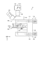
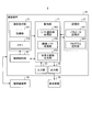
- FIG. 1 is a block diagram showing a configuration example of a microscope observation system according to Embodiment 1 of the present invention.
- FIG. 2 is a schematic diagram illustrating a configuration example of the microscope apparatus illustrated in FIG. 1.
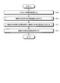
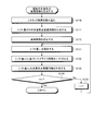
- FIG. 3 is a flowchart showing the operation of the microscope observation system shown in FIG.
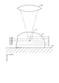
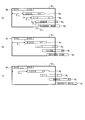
- FIG. 4 is a schematic diagram for explaining an operation of acquiring a Z stack image.
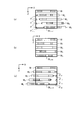
- FIG. 5 is a flowchart showing details of a process for generating a plurality of multi-focus superimposed images.
- FIG. 6 is a schematic diagram for explaining a process for generating a plurality of multi-focus superimposed images.
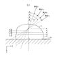
- FIG. 7 is a schematic diagram for explaining a method for setting the shift amount of the slice image.
- FIG. 1 is a block diagram showing a configuration example of a microscope observation system according to Embodiment 1 of the present invention.
- FIG. 2 is a schematic diagram illustrating a configuration example of the microscope apparatus illustrated in FIG. 1.
- FIG. 3 is
- FIG. 8 is a flowchart showing details of a process for generating a plurality of omnifocal images.
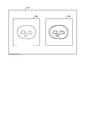
- FIG. 9 is a schematic diagram illustrating an example in which two omnifocal images are displayed side by side on the display device illustrated in FIG. 1.
- FIG. 10 is a flowchart showing details of the multi-focus superimposed image generation process in the first modification of the first embodiment of the present invention.
- FIG. 11 is a schematic diagram for explaining a method for setting the shift amount of the slice image in Modification 1 of Embodiment 1 of the present invention.
- FIG. 12 is a block diagram showing a configuration example of a microscope observation system according to Embodiment 2 of the present invention.
- FIG. 13 is a flowchart showing the operation of the microscope observation system shown in FIG. FIG.
- FIG. 14 is a flowchart showing details of a process for generating a plurality of multi-focus superimposed images.
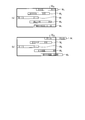
- FIG. 15 is a schematic diagram for explaining a process for generating a plurality of multi-focus superimposed images.
- FIG. 16 is a schematic diagram for explaining a process for generating a plurality of multi-focus superimposed images.
- FIG. 17 is a schematic diagram for explaining slice image shift amount calculation processing in Modification 2-2 of Embodiment 2 of the present invention.
- FIG. 18 is a schematic diagram for explaining slice image shift amount calculation processing in Modification 2-2 of Embodiment 2 of the present invention.
- FIG. 19 is a schematic diagram showing an example of a screen displayed on the display device in Modification 2-3 of Embodiment 2 of the present invention.
- FIG. 20 is a block diagram illustrating a configuration example of a microscope observation system according to Embodiment 3 of the present invention.
- FIG. 21 is a flowchart showing the operation of the microscope observation system shown in FIG.
- FIG. 22 is a schematic diagram showing a slice image shifted with respect to the reference image.
- FIG. 23 is a schematic diagram illustrating an example of a method for selecting an observation region.
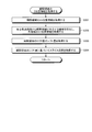
- FIG. 24 is a flowchart showing details of the processing for acquiring the Z position information of the observation area.
- FIG. 25 is a block diagram showing a configuration example of a microscope observation system according to Embodiment 4 of the present invention.
- FIG. 26 is a flowchart showing the operation of the microscope observation system shown in FIG. FIG.
- FIG. 27 is a schematic diagram for explaining the operation of the microscope observation system shown in FIG.
- FIG. 28 is a schematic diagram illustrating a slice image shift method according to a modification of the fourth embodiment.
- FIG. 29 is a schematic diagram showing another method for shifting a slice image in a modification of the fourth embodiment.
- FIG. 1 is a block diagram showing a configuration example of a microscope observation system according to Embodiment 1 of the present invention.
- a microscope observation system 1 according to Embodiment 1 includes a microscope apparatus 10 that generates an enlarged image of a subject, and an imaging apparatus that acquires and processes an image of the enlarged image generated by the microscope apparatus 10. 20 and a display device 30 that displays an image processed by the imaging device 20.
- FIG. 2 is a schematic diagram illustrating a configuration example of the microscope apparatus 10.
- the microscope apparatus 10 includes a substantially C-shaped arm 100, a lens barrel 102 and an eyepiece unit 103 supported on the arm 100 via a trinocular tube unit 101, and the arm 100.
- an objective lens 140 that forms an image of observation light from the subject S.
- the objective lens 140, the lens barrel 102 connected via the trinocular tube unit 101, and an imaging unit 211 (described later) provided on the other end side of the lens barrel 102 are an observation optical system (imaging optical system). ) 104 is configured.
- the trinocular tube unit 101 branches the observation light incident from the objective lens 140 in the direction of an eyepiece unit 103 for the user to directly observe the subject S and an imaging unit 211 described later.
- the epi-illumination unit 110 includes an epi-illumination light source 111 and an epi-illumination optical system 112 and irradiates the subject S with epi-illumination light.
- the epi-illumination optical system 112 condenses the illumination light emitted from the epi-illumination light source 111 and guides it in the direction of the optical axis L of the observation optical system 104, specifically a filter unit, a shutter, and a field of view. Including diaphragm, aperture diaphragm, etc.
- the transmitted illumination unit 120 includes a transmitted illumination light source 121 and a transmitted illumination optical system 122 and irradiates the subject S with transmitted illumination light.
- the transmission illumination optical system 122 includes various optical members that condense the illumination light emitted from the transmission illumination light source 121 and guide it in the direction of the optical axis L, specifically, a filter unit, a shutter, a field stop, an aperture stop, and the like. Including.
- any one of these epi-illumination units 110 and transmission illumination units 120 is selected and used according to the spectroscopic method.
- the microscope apparatus 10 may be provided with only one of the epi-illumination unit 110 and the transmission illumination unit 120.
- the electric stage unit 130 includes a stage 131, a stage drive unit 132 that moves the stage 131, and a position detection unit 133.
- the stage driving unit 132 is configured by, for example, a motor, and is a moving unit that moves the stage 131 under the control of the imaging control unit 22 described later.
- a subject placement surface 131 a of the stage 131 is provided so as to be orthogonal to the optical axis of the objective lens 140. In the following, it is assumed that the subject placement surface 131a is the XY plane, and the normal direction of the XY plane, that is, the direction parallel to the optical axis is the Z direction. In the Z direction, the downward direction in the figure, that is, the direction away from the objective lens 140 is the plus direction.
- the observation field of the objective lens 140 can be changed by moving the stage 131 in the XY plane. Further, by moving the stage 131 in the Z direction, the slice of the subject S positioned at the focal point of the objective lens 140 can be changed along the optical axis.
- the stage 131 can be moved by electrical control.
- the stage 131 may be manually moved by the user using an adjustment knob or the like.
- the position of the observation optical system 104 including the objective lens 140, the lens barrel 102, and the imaging unit 211 is fixed and moved on the stage 131 side, but the position of the stage 131 is fixed,
- the observation optical system 104 side may be moved.
- both the stage 131 and the observation optical system 104 may be moved in opposite directions. That is, any configuration may be used as long as the observation optical system 104 and the subject S are relatively movable.
- the position detection unit 133 is configured by an encoder that detects the amount of rotation of the stage drive unit 132 made of a motor, for example, and detects the position of the stage 131 and outputs a detection signal.
- a pulse generation unit and a stepping motor that generate pulses in accordance with the control of the imaging control unit 22 described later may be provided.
- the objective lens 140 is attached to a revolver 142 that can hold a plurality of objective lenses having different magnifications (for example, the objective lenses 140 and 141).
- the imaging magnification can be changed by rotating the revolver 142 and changing the objective lenses 140 and 141 facing the stage 131.
- FIG. 2 shows a state in which the objective lens 140 faces the stage 131.
- the imaging device 20 includes an image acquisition unit 21 that acquires an image by imaging the subject S, an imaging control unit 22 that controls the imaging operation of the image acquisition unit 21, and the imaging device 20.
- a control unit 23 that controls the various operations in the image acquisition unit 21, processes the image acquired by the image acquisition unit 21, a storage unit 24 that stores various information such as image data of the image acquired by the image acquisition unit 21 and a control program,
- the image acquisition unit 21 includes an imaging unit 211 and a memory 212.
- the image pickup unit 211 includes an image pickup device (imager) 211a made of, for example, a CCD or a CMOS, and pixel levels (R (red), G (green), and B (blue)) in each pixel included in the image pickup device 211a ( It is configured using a camera capable of capturing a color image having a pixel value. Or you may comprise the imaging part 211 using the camera which can image the monochrome image which outputs the luminance value Y as a pixel level (pixel value) in each pixel.
- the imaging unit 211 is provided at one end of the lens barrel 102 so that the optical axis L passes through the center of the light receiving surface of the imaging element 211a, and receives the light receiving surface via the objective lens 140 to the lens barrel 102.
- Image data of an image that has entered the field of view of the objective lens 140 is generated by photoelectrically converting the observation light incident on.
- the memory 212 includes a recording device such as a flash memory that can be updated and recorded, a semiconductor memory such as a RAM, and a ROM, and temporarily stores the image data generated by the imaging unit 211.
- a recording device such as a flash memory that can be updated and recorded
- a semiconductor memory such as a RAM, and a ROM
- the imaging control unit 22 outputs a control signal to the microscope apparatus 10 and moves the stage 131 to change the region of the subject S that enters the field of view of the objective lens 140 and the focal position, and causes the imaging unit 211 to perform imaging.
- a control for sequentially acquiring a plurality of images is performed.
- a set of a plurality of images having the same coordinates of the subject S on the XY plane and different focal positions is also referred to as a Z stack image.
- An image at each focal position included in the Z stack image is also referred to as a slice image.
- the control unit 23 is configured by hardware such as a CPU, for example, and by reading a program stored in the storage unit 24, based on various parameters stored in the storage unit 24, information input from the input unit 25, and the like, The overall operation of the imaging device 20 and the microscope observation system 1 is controlled. In addition, the control unit 23 generates an image by performing predetermined image processing on the image data input from the image acquisition unit 21, and further performs a process of generating an omnifocal image by combining the plurality of generated images. Do.
- control unit 23 synthesizes a plurality of slice images included in the Z stack image by combining the image shift processing unit 231 that relatively shifts the position in the image plane and the plurality of slice images. And an omnifocal image generation unit 232 that generates an omnifocal image by generating a superimposed image and restoring the multifocal superimposed image using a point spread function representing a blur of the image.
- the storage unit 24 includes a recording device such as a flash memory, RAM, and ROM that can be updated and recorded, a recording medium such as a hard disk, MO, CD-R, and DVD-R that is built-in or connected by a data communication terminal, and the like.
- a writing / reading apparatus that writes information to a recording medium and reads information recorded on the recording medium.
- the storage unit 24 includes a parameter storage unit 241 that stores parameters used for calculation in the control unit 23 and a program storage unit 242 that stores various programs.
- the parameter storage unit 241 stores parameters such as a shift amount according to the focal position when the image shift processing unit 231 shifts the slice image.
- the program storage unit 242 stores a control program for causing the imaging device 20 to execute a predetermined operation, an image processing program, and the like.
- the input unit 25 includes an input device such as a keyboard, various buttons, and various switches, a pointing device such as a mouse and a touch panel, and the like, and inputs signals corresponding to operations performed on these devices to the control unit 23. .
- the output unit 26 outputs an image based on the image data acquired by the image acquisition unit 21, an omnifocal image generated by the control unit 23, and other various information to an external device such as the display device 30, and a predetermined format This is an external interface to be displayed with.
- Such an imaging device 20 can be configured by combining a general-purpose digital camera via an external interface with a general-purpose device such as a personal computer or a workstation.
- the display device 30 is configured by, for example, an LCD, an EL display, a CRT display, or the like, and displays an image and related information output from the output unit 26.
- the display device 30 is provided outside the imaging device 20, but may be provided inside the imaging device 20.
- FIG. 3 is a flowchart showing the operation of the microscope observation system 1.
- step S ⁇ b> 10 the image acquisition unit 21 acquires a Z stack image by imaging the subject S set on the stage 131 (see FIG. 2) of the microscope apparatus 10 under the control of the imaging control unit 22.
- FIG. 4 is a schematic diagram for explaining the operation of acquiring the Z stack image, and shows the subject S placed on the slide glass SG.
- each time imaging is performed the distance between the objective lens 140 and the stage 131 is changed by ⁇ z, and the focal position F of the objective lens 140 is moved along the Z direction, so that a plurality of slices are obtained.
- FIG. 4 shows a case where five slice images are acquired by sequentially setting the focal position F to the slice positions F 1 to F 5 and capturing images five times.
- the upper limit value of the subscript j) may be set arbitrarily.
- the Z stack image is acquired in real time while imaging is performed in the imaging unit 211 provided in the microscope apparatus 10, but the Z stack image stored in the server or the like is acquired via the network.
- the Z stack image may be acquired via a storage medium.
- the image acquisition unit 21 includes an interface for inputting / outputting information to / from an external network, a reading device for reading information stored in a storage medium, and the like.
- the control unit 23 In subsequent step S11, the control unit 23 generates a plurality of multifocal superimposed images in which slice images are superimposed differently from the Z stack image acquired in step S10. Specifically, the shift amount between the multi-focus superimposed image obtained by shifting a part of the slice image in the Z stack image with a predetermined (non-zero) shift amount with respect to the other image and the slice image is set to zero. A set multi-focus superimposed image, that is, a multi-focus superimposed image that does not shift any slice image is generated.
- FIG. 5 is a flowchart showing details of the generation processing of a plurality of multifocus superimposed images in step S11.
- FIG. 6 is a schematic diagram for explaining a process for generating a plurality of multi-focus superimposed images.
- the state (XZ plane) is shown.
- processing for the slice image M j shown in FIG. 6 will be described.
- the subscript j of the slice image M j indicates the stack order in the Z stack image, and corresponds to the slice order. Further, the shaded area shown in each slice image M j indicates an area in which the structure existing at the slice position F j is shown.
- step S110 the control unit 23 reads slice images M 1 to M 5 from the image acquisition unit 21 as Z stack images.
- the control unit 23 In subsequent step S111, the control unit 23 generates multiple focuses superimposed image SI 0 shift amount zero. Specifically, the omnifocal image generation unit 232 adds and averages the pixel values of pixels corresponding to positions in the slice images M 1 to M 5 , thereby obtaining the pixel value of each pixel of the multifocal superimposed image SI 0. Is calculated. For example, as shown in FIG. 6 (a), by adding the pixel values of the pixels in each slice image M 1 ⁇ M 5 in the coordinates (x 0, y 0), the coordinates in the multi-focal superimposed image SI 0 ( The pixel value of the pixel of x 0 , y 0 ) is obtained. The image data of the multi-focus superimposed image SI 0 generated in this way is temporarily stored in the storage unit 24.
- the image shift processing unit 231 sets an arbitrary slice image M j in the Z stack image as a reference image M k (k is any one of 1 to 5).
- the reference image M k may be set as appropriate according to information input from the input unit 25 according to a user operation.
- the slice image M 1 is set as the reference image M k .
- the image shift processing unit 231 sets a shift amount ⁇ (pixel) for shifting another slice image M j with respect to the reference image M k .
- a value stored in advance in the parameter storage unit 241 may be read and set, or an arbitrary value may be set according to information (user instruction information) input from the input unit 25. good.
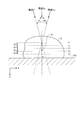
- FIG. 7 is a schematic diagram for explaining a method for setting the shift amount ⁇ of the slice image M j .
- the shift amount ⁇ is the distance z between the slice position F i of the other slice images M j to the slice position F k of the reference image M k, the angle ⁇ and the pixel pitch p of the image pickup device provided in the imaging unit 211 ( ⁇ m / pixel) and is given by the following equation (1).
- ⁇ (z ⁇ tan ⁇ ) / p (1)
- the distance z between the slice position F 1 and the slice position F 5 is shown.
- step S114 the image shift processing unit 231 shifts the slice image based on the shift amount ⁇ determined in step S113.
- FIG. 6B shows a state in which the other slice images M 2 to M 5 are shifted in the minus X direction by the shift amount ⁇ with respect to the slice image M 1 set as the reference image.
- the total focus image generation unit 232 a Z-stack images after shift processing of the slice image to generate a multi-focal superimposed image SI 1 of the shift amount sigma. That is, the pixel value of each pixel of the multifocal superimposed image SI 1 is calculated by averaging the pixel values of the pixels corresponding in position between the reference image M k and the slice image M j after the shift process. . Specifically, in the case of FIG. 6B, the pixel value of the pixel at the coordinates (x 0 , y 0 ) in the slice image M 1 that is the reference image, and the coordinates in each of the slice images M 2 to M 5 .
- the pixel value of the pixel at the coordinate (x 0 , y 0 ) in the multifocal superimposed image SI 1 is obtained by averaging the pixel values of the pixel of (x 0 + ⁇ , y 0 ).
- the image data of the multi-focus superimposed image SI 1 generated in this way is temporarily stored in the storage unit 24. Thereafter, the operation of the control unit 23 returns to the main routine.
- step S12 the omnifocal image generation unit 232 generates a plurality of omnifocal images from the plurality of multifocal superimposed images S 0 and SI 1 generated in step S11.
- FIG. 8 is a flowchart showing details of the generation processing of a plurality of omnifocal images in step S12.
- the total focus image generation unit 232 the point spread represents the image blur in each slice image M j function (point spread function: PSF) to obtain information, to generate a PSF image based on the PSF information.
- the point spread function is stored in advance in the parameter storage unit 241 in association with imaging conditions such as the magnification of the objective lens 140 in the microscope apparatus 10 and the slice position F j .
- the omnifocal image generation unit 232 reads a point spread function corresponding to the slice position F j from the parameter storage unit 241 based on the imaging conditions such as the magnification of the objective lens 140, and based on the point spread function, the slice image M j A PSF image is generated by calculating a pixel value corresponding to each pixel position.
- a shift amount corresponding to the multifocal superimposed image S 0 generates multiple focuses superimposed PSF image PI 0 zero.
- the pixel value of each pixel of the multi-focus superimposed PSF image PI 0 is calculated by averaging the pixel values of the pixels corresponding in position among the plurality of PSF images generated in step S121.
- the total focus image generation unit 232 obtains a shift amount sigma used in generating multiple focuses superimposed image SI 1, to shift the PSF image based on the shift amount sigma. That is, as in the case of generating the multifocal superimposed image SI 1 , the PSF image corresponding to the other slice image M j is shifted by the shift amount ⁇ with respect to the PSF image corresponding to the reference image M k .
- the total focus image generating unit 232 by using a plurality of PSF image after the shift processing in step S122, it generates a multi-focal superimposed PSF image PI 1 of shift sigma. Specifically, by averaging the pixel values of the pixels corresponding to the positions between the PSF image corresponding to the reference image M k and the PSF image after the shift processing corresponding to the other slice image M j. Then, the pixel value of each pixel of the multi-focus superimposed PSF image PI 1 is calculated.
- step S124 the total focus image generating unit 232, by using the multi-focal superimposed PSF image PI 0, PI 1, resulting multifocal superimposed image SI 0, SI 1 to restore, respectively, in step S11. That is, the multi-focus superimposed image SI 0 is restored by using the multi-focus superimposed PSF image PI 0 with zero shift amount to generate the omni-focus image AI 0, and the multi-focus superimposed PSF image PI i with the shift amount ⁇ is generated. generating a full-focus image AI i by restoring multiple focuses superimposed image SI i used. Thereafter, the operation of the control unit 23 returns to the main routine.
- step S13 subsequent to step S12 the imaging device 20 outputs the image data of the plurality of omnifocal images AI 0 and AI 1 generated in step S12 to the display device 30, and these omnifocal images AI 0 and AI 1 are output.
- Display The display method of the omnifocal images AI 0 and AI 1 is not particularly limited.
- the omnifocal images AI 0 and AI 1 may be displayed side by side, or the omnifocal images AI 0 and AI 1 may be alternately displayed in the same region.
- the omnifocal images AI 0 and AI 1 may be automatically switched at a predetermined cycle, or manually input to the user using the input unit 25. It is good also as making it switch with.
- FIG. 9 is a schematic diagram illustrating a display example of an omnifocal image on the display device 30.
- two omnifocal images AI 0 and AI 1 are displayed side by side. Thereafter, the operation of the microscope observation system 1 ends.
- an arbitrary slice image in the Z stack image is set as a reference image, and another slice image is set in the plane of the reference image with respect to this reference image.
- the omnifocal image is acquired by superimposing the Z stack image.
- the subject S can be virtually viewed from a plurality of viewpoints. You can reproduce what you see.
- the shift amount is set to zero and ⁇ .
- the user can visually and intuitively grasp the position in the Z direction of the structure in the subject S, the anteroposterior relationship between the structures, the overlapping state of the structures, and the like. It becomes possible.
- the first embodiment it is possible to significantly reduce the amount of calculation and the amount of data compared to the case where 3D volume data is generated and displayed based on the Z stack image.
- the omnifocal image is generated by restoring the multifocal superimposed image using the multifocal superimposed PSF image generated from the PSF image.
- each slice image is generated using the PSF image.
- An omnifocal image may be generated by superimposing the image after restoring.
- the omnifocal image generation method is not limited to this method, and a method of extracting and synthesizing a focused area from each slice image after the shift may be used.
- the slice image is shifted only in the X direction in order to facilitate understanding.
- the same processing can be performed in the Y direction.
- an omnifocal image corresponding to the case where the virtual viewpoint with respect to the subject S is moved along the Y direction can be generated.
- by shifting the slice image in two directions, the X direction and the Y direction it is possible to generate an omnifocal image corresponding to the case where the virtual viewpoint with respect to the subject S is moved in the horizontal plane.
- one omnifocal image having the shift amount ⁇ using the slice image M 1 as the reference image M k is generated.
- a plurality of appropriately selected images from the slice images M 1 to M 5 are used.
- a plurality of omnifocal images with the shift amount ⁇ may be generated by sequentially setting the slice image as the reference image M k .
- Modification 1 Next, a first modification of the first embodiment of the present invention will be described.
- the configuration and operation of the microscope observation system according to Modification 1 are generally the same as those in Embodiment 1 (see FIGS. 1 and 3), and details of the processing for generating a plurality of multifocal superimposed images in Step S11 are implemented. Different from Form 1.
- FIG. 10 is a flowchart showing details of the multi-focus superimposed image generation process in the first modification. Note that steps S110 to S112 shown in FIG. 10 are the same as those in the first embodiment (see FIG. 5).
- FIG. 11 is a schematic diagram for explaining a method of setting the slice image shift amount ⁇ i in the first modification.
- symbol i is a variable representing the number of times of shifting another slice image M j with respect to the reference image M k
- the shift amount ⁇ i a predetermined value may be determined in advance, or an arbitrary value may be determined according to information input from the input unit 25 according to a user operation.
- step S132 the image shift processing unit 231 shifts another slice image M j with respect to the reference image M k based on the shift amount ⁇ i determined in step S131.
- FIG. 11B shows a state in which the slice images M 2 to M 5 in the Z stack image shown in FIG. 11A are shifted in the minus X direction by the shift amount ⁇ 1 .
- the omnifocal image generation unit 232 generates a multifocal superimposed image SI i with the shift amount ⁇ i from the Z stack image after the shift processing of the slice image. That is, each pixel of the multifocal superimposed image SI i is obtained by averaging the pixel values of pixels corresponding to positions between the reference image M k and the slice image M j after the shift processing of the shift amount ⁇ i. The pixel value of is calculated. For (b) of FIG.
- the image data of the multi-focus superimposed image SI i generated in this way is temporarily stored in the storage unit 24.
- step S134 the control unit 23 determines whether or not the variable i has reached the maximum value n.
- step S134: No the control unit 23 increments the variable i (step S135). Thereafter, the operation of the control unit 23 returns to step S131.
- step S134 Yes
- the operation of the control unit 23 returns to the main routine.
- step S11 step S12 (see FIGS. 3 and 8) is similar to the first embodiment as a whole, in step S122 ⁇ S124 shown in FIG. 8, to produce a multi-focal superimposed image SI i
- a multi-focus superimposed PSF image is generated for each multi-focus superimposed image SI i using the shift amount ⁇ i used at the time, and the multi-focus superimposed image SI i is restored using each of these multi-focus superimposed PSF images. Is done.
- a plurality of omnifocal images having different shift amounts ⁇ i are acquired from one Z stack image.
- the omnifocal images may be displayed side by side in the order of the shift amount ⁇ i in ascending order or descending order.
- These omnifocal images may be sequentially switched and displayed in the same area. For example, a plurality of omnifocal images respectively acquired from a plurality of multifocal superimposed images SI i shown in (a) to (d) of FIG. 11 are shifted from zero shift amount ⁇ shift amount ⁇ 1 ⁇ shift amount ⁇ 2 ⁇ shift amount. Switching may be repeated in the order of ⁇ 3 ⁇ shift amount ⁇ 2 ⁇ shift amount ⁇ 1 ⁇ shift amount zero ⁇ .
- a plurality of omnifocal images having different shift amounts ⁇ i with respect to the reference image M k are acquired and displayed. It becomes possible to grasp in more detail the degree of overlap and the front-rear relationship in the Z direction between the internal structures.
- FIG. 12 is a block diagram showing a configuration example of a microscope observation system according to Embodiment 2 of the present invention.
- the microscope observation system 2 according to the second embodiment includes a microscope apparatus 10, an imaging apparatus 40 that acquires and processes an enlarged image generated by the microscope apparatus 10, and an imaging apparatus 40. And a display device 30 that displays the processed image and the like.
- the configurations and operations of the microscope apparatus 10 and the display apparatus 30 are the same as those in the first embodiment (see FIGS. 1 and 2).
- the imaging device 40 includes a control unit 41 instead of the control unit 23 shown in FIG.
- the control unit 41 further includes a shift amount acquisition processing unit 411 with respect to the control unit 23.
- the configuration and operation of each unit of the imaging apparatus 40 other than the control unit 41 and the operations of the image shift processing unit 231 and the omnifocal image generation unit 232 are the same as those in the first embodiment.
- the shift amount acquisition processing unit 411 acquires the shift amount of each of the other slice images with respect to the reference image, which is used when generating the multifocus superimposed image from the Z stack image. This shift amount is acquired based on shift parameters stored in advance in the parameter storage unit 241.
- the shift parameter includes the direction of the virtual viewpoint with respect to the subject S and the unit shift amount of the slice image set for each viewpoint.
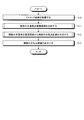
- FIG. 13 is a flowchart showing the operation of the microscope observation system 2.
- Step S10 shown in FIG. 13 is the same as that in the first embodiment (see FIG. 3), but in the second embodiment, at least three slice images having different focal positions are obtained by performing imaging at least three times.
- a Z stack image is acquired. In the following, as will be described later, processing for a Z stack image composed of five slice images will be described.
- step S21 following step S10 the control unit 41 generates a plurality of multifocus superimposed images having different shift amounts of slice images.
- FIG. 14 is a flowchart showing details of a process for generating a plurality of multi-focus superimposed images.
- FIGS. 15 and 16 are schematic diagrams for explaining a process for generating a plurality of multi-focus superimposed images.
- step S210 the shift amount acquisition processing unit 411 reads a Z stack image from the image acquisition unit 21.
- the shift amount acquisition processing unit 411 sets an arbitrary slice image M j in the Z stack image as the reference image M k .
- the reference image M k may be set as appropriate according to information input from the input unit 25 according to a user operation.
- the slice image M 1 is set as the reference image M k .
- step S ⁇ b> 212 the shift amount acquisition processing unit 411 acquires a shift parameter from the parameter storage unit 241.
- the parameter ⁇ ⁇ 1, 0, +1 representing the viewpoint V ⁇ and the unit shift amount ⁇ are acquired as the shift parameters.
- the parameter ⁇ zero, it means that the viewpoint V ⁇ is set right above the subject S.
- the parameter ⁇ is a positive value, it means that the viewpoint V ⁇ is set in the + X direction with respect to the subject S.
- the parameter ⁇ is a negative value, it means that the viewpoint V ⁇ is set in the ⁇ X direction directly above the subject S.
- the shift amount acquisition processing unit 411 calculates the shift amount ⁇ ⁇ j of each slice image M j based on the shift parameter acquired in step S212.
- This shift amount ⁇ ⁇ j is sequentially calculated for each viewpoint V ⁇ .
- the shift amount ⁇ ⁇ j is given by the following equation (2) using the unit shift amount ⁇ (pixel).
- ⁇ ⁇ j ⁇ ⁇ ⁇ ⁇ (j ⁇ k) ⁇ (2)
- the image shift processing unit 231 shifts the slice image M j based on the shift amount ⁇ ⁇ j calculated in step S213.
- the slice image M j is shifted in the + X direction
- the sign of the shift amount ⁇ ⁇ j is negative
- the slice image M j is shifted in the ⁇ X direction.
- the shift amount ⁇ ⁇ j is zero
- the slice image M j is not shifted.
- FIG. 16A shows that the other slice images M 2 to M 5 are shifted by shift amounts ⁇ -12 , ⁇ -13 , ⁇ -14 , and ⁇ -15 with respect to the slice image M 1 that is the reference image. It shows the state that was made to.
- step S216 the control unit 41 determines whether or not processing has been performed for all viewpoints based on the shift parameter acquired in step S212. If there is still a viewpoint that has not been processed (step S216: No), the shift amount acquisition processing unit 411 changes the parameter ⁇ (step S217), and steps S213 to S216 are performed based on the changed parameter ⁇ . Repeat the process.
- the shift amounts ⁇ 02 to ⁇ 05 of the slice images M 2 to M 5 are all zero.
- step S216: Yes the operation of the control unit 41 returns to the main routine.
- step S12 following step S21 is generally the same as in the first embodiment, but in steps S122 to S124, the multifocal superimposed image SI ⁇ is generated.
- a multi-focus superimposed PSF image is generated for each multi-focus superimposed image SI ⁇ using the shift amount ⁇ ⁇ j of each slice image M j used, and a multi-focus superimposed image is generated using each of these multi-focus superimposed PSF images.
- SI ⁇ is restored.
- a plurality of omnifocal images having different shift amounts ⁇ ⁇ j are acquired from one Z stack image.
- the second embodiment of the present invention it is possible to reproduce a state in which the subject S is virtually observed from a plurality of directions by using a plurality of omnifocal images having different shift amounts. Therefore, the user can more intuitively grasp the position in the Z direction of the structure in the subject S, the degree of overlap between the structures, and the front-rear relationship.
- ⁇ ⁇ j ⁇ (d j, k ⁇ tan ⁇ ⁇ ) / p (4)
- the distance d 4,1 between the slice position F 1 and the slice position F 4 is shown.
- Modification 2-2 of Embodiment 2 of the present invention will be described.
- the configuration and operation of the microscope observation system according to the modified example 2-2 are generally the same as those in the second embodiment (see FIGS. 12 and 13).
- FIGS. 17 and 18 are schematic diagrams for explaining the calculation processing of the shift amount ⁇ ⁇ j of the slice image in Modification 2-2.
- the shift amount ⁇ ⁇ j of each slice image M j when generating the multifocal superimposed image SI ⁇ increases as the angle ⁇ of the virtual viewpoint V ⁇ increases.
- the viewpoints V 1 , V 2 ,... are changed in one direction (rightward in FIG. 17) with respect to the direction directly above the subject S. You may change to both right and left with respect to the direction.
- the shift amount of each slice image M j is determined according to the shift parameter stored in advance in the parameter storage unit 241.
- the shift amount may be determined according to a user operation.
- control unit 41 first generates a plurality of omnifocal images based on the shift parameters stored in advance in the parameter storage unit 241 and causes the display device 30 to display them. Then, an input field for allowing the user to input the viewpoint V ⁇ is displayed on the display device 30.
- FIG. 19 is a schematic diagram illustrating an example of a screen displayed on the display device 30.
- This screen m2 includes a omnifocal image display area m3 in which a plurality of omnifocal image is displayed by switching, and a perspective input field m4 for inputting a viewpoint V alpha to the user.
- the view input field m4, and scale m5 indicating the angle ⁇ of the viewpoint V alpha is displayed.
- the pointer operation using the input unit 25 for the scale m5 when the user desired angle theta alpha is selected, a signal representing the angle theta alpha is input to the control unit 41.
- the control unit 41 generates an omnifocal image by calculating the shift amount ⁇ ⁇ j corresponding to the angle ⁇ ⁇ and causes the display device 30 to display it.
- Modification 2-3 it is possible to reproduce the state in which the subject S is observed from the viewpoint desired by the user. Therefore, it is possible to adjust the position in the Z direction of the structure in the subject S, the degree of overlap between the structures, and the front-rear relationship so that the user can easily see.
- FIG. 20 is a block diagram illustrating a configuration example of a microscope observation system according to Embodiment 3 of the present invention.
- the microscope observation system 3 according to the third embodiment includes a microscope device 10, an imaging device 50 that acquires and processes an enlarged image generated by the microscope device 10, and an imaging device 50. And a display device 60 that displays the processed image and the like.
- the configuration and operation of the microscope apparatus 10 are the same as those in the first embodiment (see FIG. 2).
- the imaging device 50 includes a control unit 51 instead of the control unit 23 shown in FIG.
- the control unit 51 further includes a shift amount acquisition processing unit 411 and an attention image determination processing unit 511 with respect to the control unit 23.
- the operation of the shift amount acquisition processing unit 411 is the same as that of the second embodiment.
- the attention image determination processing unit 511 determines, as the attention image, a slice image including an observation region input from the display device 60 described later via the input unit 25.
- the display device 60 is configured by, for example, an LCD, an EL display, a CRT display, or the like, and an image display unit 61 that displays an image output from the output unit 26 and related information, and an image display unit according to an operation performed from the outside.
- An observation area determination unit 62 that determines an area in the omnifocal image displayed on 61 as an observation area and inputs a signal representing the observation area to the control unit 51.
- FIG. 21 is a flowchart showing the operation of the microscope observation system 3.
- the operations in steps S10, S21, S12, and S13 are the same as those in the second embodiment.
- FIG. 6 is a schematic diagram showing a state where 5 is shifted.
- step S31 No
- the operation of the microscope observation system 3 returns to step S13.
- FIG. 23 is a schematic diagram illustrating an example of a method for selecting an observation region.
- the observation region is selected by surrounding a desired region in the omnifocal image displayed on the image display unit 61 by a pointer operation using a mouse or the like.
- step S ⁇ b> 33 the control unit 51 acquires the Z position information of the observation region based on the information indicating the observation region input from the observation region determination unit 62.
- FIG. 24 is a flowchart showing details of the processing for acquiring the Z position information of the observation area.
- the shift amount ⁇ ⁇ j of each slice image M j in the omnifocal image AI ⁇ is given by the following equation (6) as described in the second embodiment. Therefore, given the shift amount
- ⁇ ⁇ j ⁇ ⁇ ⁇ ⁇ (j ⁇ k) ⁇ (6)
- the attention image determination processing unit 511 outputs the slice position F j acquired in this way as the Z position information of the observation region. Thereafter, the operation of the control unit 51 returns to the main routine.
- step S34 following step S33 the control unit 51 extracts and outputs a slice image M j including an observation region based on the Z position information output by the attention image determination processing unit 511.
- the display device 60 displays the slice image M j including the observation region.
- other (i.e., front and rear) of the slice locations are adjacent on the slice image M j may be displayed slice image.
- the user can intuitively and easily grasp the position in the Z direction of the structures that appear to overlap each other on the plane and the front-rear relationship between the structures.
- FIG. 25 is a block diagram showing a configuration example of a microscope observation system according to Embodiment 4 of the present invention.
- the microscope observation system 4 according to the fourth embodiment includes a microscope apparatus 10, an imaging apparatus 70 that acquires and processes an enlarged image generated by the microscope apparatus 10, and an imaging apparatus 70. And a display device 60 that displays the processed image and the like.
- the configuration and operation of the microscope apparatus 10 are the same as those in the first embodiment (see FIG. 2).
- the configuration and operation of the display device 60 are the same as those in the third embodiment (see FIG. 20).
- the imaging device 70 includes a control unit 71 instead of the control unit 51 shown in FIG.
- the control unit 71 includes an omnifocal image generation unit 711 instead of the omnifocal image generation unit 232 with respect to the control unit 51.
- the configuration and operation of each unit of the imaging device 70 other than the control unit 71 and the configuration and operation of each unit of the control unit 71 other than the omnifocal image generation unit 711 are the same as those in the third embodiment.
- the omnifocal image generation unit 711 includes a cutout range determination processing unit 712 that cuts out a range of the multifocal superimposed image used for generation of the omnifocal image, and the omnifocal image is generated from the range cut out by the cutout range determination processing unit 712. Generate.
- FIG. 26 is a flowchart showing the operation of the microscope observation system 4. Steps S10 to S34 are the same as in the third embodiment (see FIG. 21).
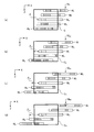
- FIG. 27 is a schematic diagram for explaining the operation of the microscope observation system 4. In the following description, the observation area determined in step S32 is, it is assumed that was found to contain the slice image M 3 (see step S33).
- step S41 following step S34 the shift amount obtaining unit 411, sets the slice image M 3 including the observation area determined in step S32 to the new reference image.
- the shift amount acquisition processing unit 411 acquires the shift amount of another slice image M j with respect to a new reference image when generating a multifocal superimposed image from the original Z stack image.
- This shift amount determination method can be calculated using Equation (2), as in the second embodiment.
- FIGS. 27A to 27D show cases where the shift amounts of other slice images M j with respect to the slice image M 3 as the reference image are set to ⁇ 1 , ⁇ 2 , ⁇ 3 , and ⁇ 4 , respectively. ing. Note that the shift amount between the slice images M j in each multi-focus superimposed image is the same.
- the image shift processing unit 231 shifts another slice image M j with respect to the new reference image based on the shift amounts ⁇ 1 , ⁇ 2 , ⁇ 3 , and ⁇ 4 acquired in step S42.
- the omnifocal image generation unit 711 regenerates a plurality of multifocal superimposed images SI 01 , SI 02 , SI 03 , SI 04 from the reference image after this shift processing and the other slice images M j .
- the method for generating the multifocal superimposed image is the same as in the second embodiment.
- the cutout range determination processing unit 712 determines the XY position of the observation region determined in step S32 for the multiple multifocal superimposed images SI 01 , SI 02 , SI 03 , SI 04 regenerated in step S43.
- the cutout range to be cut out from each multi-focus superimposed image SI 01 , SI 02 , SI 03 , SI 04 is determined so as not to change.
- the clipping ranges C 1 to C 4 shown in FIGS. 27A to 27D are set.
- the cutout ranges C 1 to C 4 are set so that the X position of the slice image M 3 is constant.
- the omnifocal image generation unit 711 cuts out each multi-focus superimposed image SI 01 , SI 02 , SI 03 , SI 04 in the cut-out range determined in step S44, and performs restoration processing on the cut-out range. By executing this, an omnifocal image is generated.
- step S46 the imaging device 70 causes the display device 60 to display the plurality of omnifocal images generated in step S45. Thereafter, the operation of the microscope observation system 4 ends.
- a plurality of omnifocal images with different virtual viewpoints can be displayed without changing the position of the observation region selected by the user in the omnifocal image. Therefore, the user can intuitively grasp the position of the observation region in the Z direction, the front-rear relationship with other structures, and the like without changing the line of sight with respect to the observation region selected by the user.
- FIG. 28 is a schematic diagram showing a slice image shift method in a modification of the fourth embodiment, and shows three multi-focus superimposed images using the slice image M 1 as a reference image.
- a shift amount between the same slice images (for example, a shift amount of the slice image M 2 with respect to the slice image M 1) between the multifocal superimposed images SI 11 , SI 12 , and SI 13 shown in FIGS. ) Increases in the order of the multi-focus superimposed images SI 11 , SI 12 , SI 13 ( ⁇ 11 ⁇ 21 ⁇ 31 ).
- the closer the slice position on the slice image M 1 is in each multifocal superimposed image it has many shift amount between the slice images.
- the shift amounts have a relationship of ⁇ 11 > ⁇ 12 > ⁇ 13 > ⁇ 14 in order from the closest to the slice image M 1 .
- the shift amount is sequentially increased or sequentially increased with respect to the highest slice image M 1 or the lowest slice image M 5 so that the slice images M 1 to M 5 are arranged in one direction. Decreased.
- the increase or decrease of the shift amount may be changed according to the positional relationship of the slice images.
- FIG. 29 is a schematic diagram showing another method of shifting a slice image in a modification of the fourth embodiment, and shows two multi-focus superimposed images using the slice image M 3 as a reference image.
- the shift amount is increased or decreased according to the slice position with the slice image M 3 as a boundary.
- Embodiments 1 to 4 and the modifications described above are not limited as they are, and various inventions are formed by appropriately combining a plurality of constituent elements disclosed in the embodiments and modifications. be able to. For example, some components may be excluded from all the components shown in the embodiment. Or you may form combining the component shown in different embodiment suitably.
- Microscope observation system 10 Microscope device 20, 40, 50, 70 Imaging device 21 Image acquisition unit 22 Imaging control unit 23, 41, 51, 71 Control unit 24 Storage unit 25 Input unit 26 Output unit 30, DESCRIPTION OF SYMBOLS 60 Display apparatus 61 Image display part 62 Observation area determination part 100 Arm 101 Trinocular tube unit 102 Lens tube 103 Eyepiece unit 104 Observation optical system 110 Epi-illumination unit 111 Epi-illumination light source 112 Epi-illumination optical system 120 Transmission illumination unit 121 Transmission Illumination light source 122 Transmission illumination optical system 130 Electric stage unit 131 Stage 132 Stage drive unit 133 Position detection unit 140, 141 Objective lens 142 Revolver 211 Imaging unit 212 Memory 231 Image shift processing unit 232, 711 All-focus image generation unit 241 Parameter Data storage unit 242 program storage unit 411 shift amount acquisition processing unit 511 attention image determination processing unit 712 clipping range determination processing unit
Landscapes
- Engineering & Computer Science (AREA)
- Physics & Mathematics (AREA)
- General Physics & Mathematics (AREA)
- Multimedia (AREA)
- Theoretical Computer Science (AREA)
- Optics & Photonics (AREA)
- Analytical Chemistry (AREA)
- Chemical & Material Sciences (AREA)
- Computer Vision & Pattern Recognition (AREA)
- Computing Systems (AREA)
- Signal Processing (AREA)
- Microscoopes, Condenser (AREA)
- Image Processing (AREA)
- Image Analysis (AREA)
Abstract
Description
図1は、本発明の実施の形態1に係る顕微鏡観察システムの構成例を示すブロック図である。図1に示すように、実施の形態1に係る顕微鏡観察システム1は、被写体の拡大像を生成する顕微鏡装置10と、該顕微鏡装置10が生成した拡大像の画像を取得して処理する撮像装置20と、撮像装置20が処理した画像を表示する表示装置30とを備える。
σ=(z・tanθ)/p …(1)
なお、図7においては、スライス位置F1とスライス位置F5との距離zを示している。
次に、本発明の実施の形態1の変形例1について説明する。変形例1に係る顕微鏡観察システムの構成及び動作は、全体として実施の形態1と同様であり(図1、図3参照)、ステップS11における複数の多重焦点重畳画像の生成処理の詳細が実施の形態1と異なる。
次に、本発明の実施の形態2について説明する。図12は、本発明の実施の形態2に係る顕微鏡観察システムの構成例を示すブロック図である。図12に示すように、実施の形態2に係る顕微鏡観察システム2は、顕微鏡装置10と、該顕微鏡装置10が生成した拡大像の画像を取得して処理する撮像装置40と、撮像装置40が処理した画像等を表示する表示装置30とを備える。このうち、顕微鏡装置10及び表示装置30の構成及び動作は、実施の形態1と同様である(図1及び図2参照)。
σαj=-α×{δ×(j-k)} …(2)
σ-11=-(-1)×{1×(1-1)}=0(ピクセル) …(3-1)
σ-12=-(-1)×{1×(2-1)}=+1(ピクセル)…(3-2)
σ-13=-(-1)×{1×(3-1)}=+2(ピクセル)…(3-3)
σ-14=-(-1)×{1×(4-1)}=+3(ピクセル)…(3-4)
σ-15=-(-1)×{1×(5-1)}=+4(ピクセル)…(3-5)
次に、本発明の実施の形態2の変形例2-1について説明する。上記実施の形態2においては、単位シフト量δを用いて、視点Vαごとに各スライス画像Mjのシフト量σαjを算出したが、各視点Vαの方向を表すθ(図15においてはθ=-θ0、0、+θ0)を用いてシフト量σαjを算出しても良い。
σαj=-(dj,k・tanθα)/p …(4)
なお、図15においては、スライス位置F1とスライス位置F4との距離d4,1を示している。
次に、本発明の実施の形態2の変形例2-2について説明する。変形例2-2に係る顕微鏡観察システムの構成及び動作は、全体として実施の形態2と同様であり(図12及び図13参照)、ステップS21の複数の多重焦点重畳画像の生成処理のうち、図14に示すステップS213においてシフト量σαjの算出処理を実行する際に、さらに視点Vαを増やす場合について説明する。図17及び図18は、変形例2-2におけるスライス画像のシフト量σαjの算出処理を説明するための模式図である。
σαj=-α×{δ×(j-k)} …(2)
次に、上記実施の形態2の変形例2-3について説明する。上記実施の形態2においては、パラメータ記憶部241に予め記憶されているシフトパラメータに従って、各スライス画像Mjのシフト量を決定したが、このシフト量をユーザ操作に従って決定しても良い。
次に、本発明の実施の形態3について説明する。図20は、本発明の実施の形態3に係る顕微鏡観察システムの構成例を示すブロック図である。図20に示すように、実施の形態3に係る顕微鏡観察システム3は、顕微鏡装置10と、該顕微鏡装置10が生成した拡大像の画像を取得して処理する撮像装置50と、撮像装置50が処理した画像等を表示する表示装置60とを備える。このうち、顕微鏡装置10の構成及び動作は、実施の形態1と同様である(図2参照)。
σαj=-α×{δ×(j-k)} …(6)
|σαj-σ(α+1)j|=|{α-(α+1)}×{δ×(j-k)}|
|σαj-σ(α+1)j|=|δ×(j-k)| …(7)
次に、本発明の実施の形態4について説明する。図25は、本発明の実施の形態4に係る顕微鏡観察システムの構成例を示すブロック図である。図25に示すように、実施の形態4に係る顕微鏡観察システム4は、顕微鏡装置10と、該顕微鏡装置10が生成した拡大像の画像を取得して処理する撮像装置70と、撮像装置70が処理した画像等を表示する表示装置60とを備える。このうち、顕微鏡装置10の構成及び動作は、実施の形態1と同様である(図2参照)。また、表示装置60の構成及び動作は、実施の形態3と同様である(図20参照)。
次に、本発明の実施の形態4の変形例について説明する。上記実施の形態4では、各多重焦点重畳画像内において隣り合うスライス画像間のシフト量を同一としたが(ステップS42参照)、1つの多重焦点重畳画像内においても、隣り合うスライス画像間のシフト量を変化させても良い。
10 顕微鏡装置
20、40、50、70 撮像装置
21 画像取得部
22 撮像制御部
23、41、51、71 制御部
24 記憶部
25 入力部
26 出力部
30、60 表示装置
61 画像表示部
62 観察領域決定部
100 アーム
101 三眼鏡筒ユニット
102 鏡筒
103 接眼レンズユニット
104 観察光学系
110 落射照明ユニット
111 落射照明用光源
112 落射照明光学系
120 透過照明ユニット
121 透過照明用光源
122 透過照明光学系
130 電動ステージユニット
131 ステージ
132 ステージ駆動部
133 位置検出部
140、141 対物レンズ
142 レボルバ
211 撮像部
212 メモリ
231 画像シフト処理部
232、711 全焦点画像生成部
241 パラメータ記憶部
242 プログラム記憶部
411 シフト量取得処理部
511 注目画像決定処理部
712 切り出し範囲決定処理部
Claims (6)
- 顕微鏡が備える観察光学系の光軸に沿って焦点位置をずらしながら被写体像を撮像することにより生成された複数のスライス画像を取得する画像取得部と、
前記複数のスライス画像のうちの1のスライス画像に対して他のスライス画像を、当該1のスライス画像が含まれる面内において相対的にシフトさせる画像シフト処理部と、
前記1のスライス画像と、該1のスライス画像に対して相対的にシフトさせた前記他のスライス画像とを、前記1のスライス画像に対する前記他のスライス画像のシフト量が異なる複数の条件の下で合成することにより、複数の全焦点画像を生成する全焦点画像生成部と、
前記複数の全焦点画像を表示する表示部と、
を備えることを特徴とする顕微鏡観察システム。 - 外部からなされる操作に応じた情報を入力する入力部と、
前記入力部から入力された情報に従って、前記複数の条件の各々における前記シフト量を算出するシフト量取得処理部と、
をさらに備え、
前記画像シフト処理部は、前記シフト量取得処理部が算出した前記シフト量に従って、前記他のスライス画像をシフトさせる、
ことを特徴とする請求項1に記載の顕微鏡観察システム。 - 外部からなされる操作に応じて前記複数の全焦点画像のうちのいずれかの全焦点画像から選択された領域を観察領域として決定する観察領域決定処理部と、
前記観察領域が選択された全焦点画像以外の全焦点画像から前記観察領域に対応する領域を抽出すると共に、前記観察領域が選択された全焦点画像における前記観察領域の位置と、前記領域が抽出された全焦点画像における前記領域の位置との間のシフト量に基づいて、前記複数のスライス画像から前記観察領域が含まれるスライス画像を抽出する注目画像抽出処理部と、
をさらに備えることを特徴とする請求項1に記載の顕微鏡観察システム。 - 前記全焦点画像生成部は、前記観察領域が選択された全焦点画像における前記観察領域の位置に基づき、前記1のスライス画像と、該1のスライス画像に対して相対的にシフトさせた前記他のスライス画像とに対し、前記複数の全焦点画像の各々を生成する際に用いる範囲を決定する切り出し範囲決定処理部をさらに備える、ことを特徴とする請求項3に記載の顕微鏡観察システム。
- 顕微鏡が備える観察光学系の光軸に沿って焦点位置をずらしながら被写体像を撮像することにより生成された複数のスライス画像を取得する画像取得ステップと、
前記複数のスライス画像のうちの1のスライス画像に対して他のスライス画像を、当該1のスライス画像が含まれる面内において相対的にシフトさせる画像シフト処理ステップと、
前記1のスライス画像と、該1のスライス画像に対して相対的にシフトさせた前記他のスライス画像とを、前記1のスライス画像に対する前記他のスライス画像のシフト量が異なる複数の条件の下で合成することにより、複数の全焦点画像を生成する全焦点画像生成ステップと、
前記複数の全焦点画像を表示する表示ステップと、
を含むことを特徴とする顕微鏡観察方法。 - 顕微鏡が備える観察光学系の光軸に沿って焦点位置をずらしながら被写体像を撮像することにより生成された複数のスライス画像に対し、前記複数のスライス画像のうちの1のスライス画像に対して他のスライス画像を、当該1のスライス画像が含まれる面内において相対的にシフトさせる画像シフト処理ステップと、
前記1のスライス画像と、該1のスライス画像に対して相対的にシフトさせた前記他のスライス画像とを、前記1のスライス画像に対する前記他のスライス画像のシフト量が異なる複数の条件の下で合成することにより、複数の全焦点画像を生成する全焦点画像生成ステップと、
前記複数の全焦点画像を表示する表示ステップと、
をコンピュータに実行させることを特徴とする顕微鏡観察プログラム。
Priority Applications (4)
| Application Number | Priority Date | Filing Date | Title |
|---|---|---|---|
| DE112015006312.9T DE112015006312T5 (de) | 2015-04-15 | 2015-04-15 | Mikroskopiesystem, Mikroskopieverfahren und Mikroskopieprogramm |
| PCT/JP2015/061640 WO2016166858A1 (ja) | 2015-04-15 | 2015-04-15 | 顕微鏡観察システム、顕微鏡観察方法、及び顕微鏡観察プログラム |
| JP2017512142A JPWO2016166858A1 (ja) | 2015-04-15 | 2015-04-15 | 顕微鏡観察システム、顕微鏡観察方法、及び顕微鏡観察プログラム |
| US15/782,108 US10429632B2 (en) | 2015-04-15 | 2017-10-12 | Microscopy system, microscopy method, and computer-readable recording medium |
Applications Claiming Priority (1)
| Application Number | Priority Date | Filing Date | Title |
|---|---|---|---|
| PCT/JP2015/061640 WO2016166858A1 (ja) | 2015-04-15 | 2015-04-15 | 顕微鏡観察システム、顕微鏡観察方法、及び顕微鏡観察プログラム |
Related Child Applications (1)
| Application Number | Title | Priority Date | Filing Date |
|---|---|---|---|
| US15/782,108 Continuation US10429632B2 (en) | 2015-04-15 | 2017-10-12 | Microscopy system, microscopy method, and computer-readable recording medium |
Publications (1)
| Publication Number | Publication Date |
|---|---|
| WO2016166858A1 true WO2016166858A1 (ja) | 2016-10-20 |
Family
ID=57125912
Family Applications (1)
| Application Number | Title | Priority Date | Filing Date |
|---|---|---|---|
| PCT/JP2015/061640 Ceased WO2016166858A1 (ja) | 2015-04-15 | 2015-04-15 | 顕微鏡観察システム、顕微鏡観察方法、及び顕微鏡観察プログラム |
Country Status (4)
| Country | Link |
|---|---|
| US (1) | US10429632B2 (ja) |
| JP (1) | JPWO2016166858A1 (ja) |
| DE (1) | DE112015006312T5 (ja) |
| WO (1) | WO2016166858A1 (ja) |
Cited By (1)
| Publication number | Priority date | Publication date | Assignee | Title |
|---|---|---|---|---|
| JPWO2016166871A1 (ja) * | 2015-04-16 | 2018-02-08 | オリンパス株式会社 | 顕微鏡観察システム、顕微鏡観察方法、及び顕微鏡観察プログラム |
Families Citing this family (4)
| Publication number | Priority date | Publication date | Assignee | Title |
|---|---|---|---|---|
| US10896482B2 (en) * | 2017-05-11 | 2021-01-19 | Lockheed Martin Corporation | Slice scan imaging system and methods of use |
| CN109374621A (zh) * | 2018-11-07 | 2019-02-22 | 杭州迪英加科技有限公司 | 切片扫描仪的对焦方法、系统和装置 |
| CN110673325A (zh) * | 2019-09-25 | 2020-01-10 | 腾讯科技(深圳)有限公司 | 显微镜系统、智能医疗设备、自动对焦方法和存储介质 |
| WO2022076361A1 (en) * | 2020-10-05 | 2022-04-14 | Thrive Bioscience, Inc. | Method and apparatus for displaying cultured cells |
Citations (5)
| Publication number | Priority date | Publication date | Assignee | Title |
|---|---|---|---|---|
| JPH08161530A (ja) * | 1994-12-09 | 1996-06-21 | Olympus Optical Co Ltd | アイコン作成方法及び動画用のコマ作成方法 |
| JP2008067915A (ja) * | 2006-09-14 | 2008-03-27 | Canon Inc | 医用画像表示装置 |
| WO2013069215A1 (ja) * | 2011-11-10 | 2013-05-16 | ソニー株式会社 | 画像処理装置、画像処理方法、および画像ファイルのデータ構造 |
| JP2014021489A (ja) * | 2012-07-19 | 2014-02-03 | Sony Corp | 顕微鏡法における被写界深度(dof)を改善するための方法及び装置 |
| JP2014021490A (ja) * | 2012-07-19 | 2014-02-03 | Sony Corp | スタックされた顕微鏡画像をナビゲートするための方法及び装置 |
Family Cites Families (1)
| Publication number | Priority date | Publication date | Assignee | Title |
|---|---|---|---|---|
| SG140484A1 (en) * | 2006-08-24 | 2008-03-28 | Sony Corp | An electron emitter and a display apparatus utilizing the same |
-
2015
- 2015-04-15 JP JP2017512142A patent/JPWO2016166858A1/ja active Pending
- 2015-04-15 DE DE112015006312.9T patent/DE112015006312T5/de not_active Withdrawn
- 2015-04-15 WO PCT/JP2015/061640 patent/WO2016166858A1/ja not_active Ceased
-
2017
- 2017-10-12 US US15/782,108 patent/US10429632B2/en active Active
Patent Citations (5)
| Publication number | Priority date | Publication date | Assignee | Title |
|---|---|---|---|---|
| JPH08161530A (ja) * | 1994-12-09 | 1996-06-21 | Olympus Optical Co Ltd | アイコン作成方法及び動画用のコマ作成方法 |
| JP2008067915A (ja) * | 2006-09-14 | 2008-03-27 | Canon Inc | 医用画像表示装置 |
| WO2013069215A1 (ja) * | 2011-11-10 | 2013-05-16 | ソニー株式会社 | 画像処理装置、画像処理方法、および画像ファイルのデータ構造 |
| JP2014021489A (ja) * | 2012-07-19 | 2014-02-03 | Sony Corp | 顕微鏡法における被写界深度(dof)を改善するための方法及び装置 |
| JP2014021490A (ja) * | 2012-07-19 | 2014-02-03 | Sony Corp | スタックされた顕微鏡画像をナビゲートするための方法及び装置 |
Cited By (1)
| Publication number | Priority date | Publication date | Assignee | Title |
|---|---|---|---|---|
| JPWO2016166871A1 (ja) * | 2015-04-16 | 2018-02-08 | オリンパス株式会社 | 顕微鏡観察システム、顕微鏡観察方法、及び顕微鏡観察プログラム |
Also Published As
| Publication number | Publication date |
|---|---|
| JPWO2016166858A1 (ja) | 2018-02-08 |
| US10429632B2 (en) | 2019-10-01 |
| DE112015006312T5 (de) | 2017-12-28 |
| US20180081161A1 (en) | 2018-03-22 |
Similar Documents
| Publication | Publication Date | Title |
|---|---|---|
| US20210312596A1 (en) | Image processing device, image processing program, image processing method, and imaging device | |
| JP6563486B2 (ja) | 顕微鏡観察システム、顕微鏡観察方法、及び顕微鏡観察プログラム | |
| JP5555014B2 (ja) | バーチャルスライド作成装置 | |
| US10429632B2 (en) | Microscopy system, microscopy method, and computer-readable recording medium | |
| JP6548367B2 (ja) | 画像処理装置、撮像装置、画像処理方法及びプログラム | |
| EP2786340A1 (en) | Image processing apparatus and image processing method | |
| US11109916B2 (en) | Personalized hand-eye coordinated digital stereo microscopic systems and methods | |
| EP3151719B1 (en) | Image processing apparatus and program | |
| JP2024019639A (ja) | 顕微鏡システム、プログラム、及び、投影画像生成方法 | |
| JP2013211827A (ja) | 画像処理方法および装置、プログラム。 | |
| JP2018181333A (ja) | 医学−光学式表示システムを作動させるための方法 | |
| US10721413B2 (en) | Microscopy system, microscopy method, and computer readable recording medium | |
| WO2015107872A1 (en) | Image acquisition apparatus and control method thereof | |
| US10089768B2 (en) | Image processing device, image processing method, image processing program, and imaging system | |
| JP6736670B2 (ja) | 内視鏡システム | |
| WO2025088159A1 (en) | Endoscopic systems and methods for imaging an object | |
| JP2017143759A (ja) | 細胞観察装置および細胞観察方法 | |
| JP6312410B2 (ja) | アライメント装置、顕微鏡システム、アライメント方法、及びアライメントプログラム | |
| JP6422761B2 (ja) | 顕微鏡システム、及び、z位置と補正装置の設定値との関係算出方法 | |
| WO2024178045A1 (en) | Systems, methods, and devices providing fluorescence microscopy confocally sectioned images | |
| JP4346888B2 (ja) | 顕微鏡装置 | |
| CN114730070B (zh) | 图像处理方法、图像处理装置和图像处理系统 | |
| JP2024104391A (ja) | 焦点位置推定方法、焦点位置推定プログラム、焦点位置推定システム、モデル生成方法、モデル生成プログラム、モデル生成システム及び焦点位置推定モデル | |
| WO2012049022A1 (en) | Method and device for digital image processing | |
| JP2016114796A (ja) | 顕微鏡システム、関数算出方法、及び、プログラム |
Legal Events
| Date | Code | Title | Description |
|---|---|---|---|
| 121 | Ep: the epo has been informed by wipo that ep was designated in this application |
Ref document number: 15889196 Country of ref document: EP Kind code of ref document: A1 |
|
| ENP | Entry into the national phase |
Ref document number: 2017512142 Country of ref document: JP Kind code of ref document: A |
|
| WWE | Wipo information: entry into national phase |
Ref document number: 112015006312 Country of ref document: DE |
|
| 122 | Ep: pct application non-entry in european phase |
Ref document number: 15889196 Country of ref document: EP Kind code of ref document: A1 |