WO2016166832A1 - Turbocharger - Google Patents

Turbocharger Download PDF

Info

Publication number
WO2016166832A1
WO2016166832A1 PCT/JP2015/061569 JP2015061569W WO2016166832A1 WO 2016166832 A1 WO2016166832 A1 WO 2016166832A1 JP 2015061569 W JP2015061569 W JP 2015061569W WO 2016166832 A1 WO2016166832 A1 WO 2016166832A1
Authority
WO
WIPO (PCT)
Prior art keywords
sleeve
turbocharger
rolling bearing
rotating shaft
outer ring
Prior art date
Application number
PCT/JP2015/061569
Other languages
French (fr)
Japanese (ja)
Inventor
善友 野田
幹 惠比寿
Original Assignee
三菱重工業株式会社
Priority date (The priority date is an assumption and is not a legal conclusion. Google has not performed a legal analysis and makes no representation as to the accuracy of the date listed.)
Filing date
Publication date
Application filed by 三菱重工業株式会社 filed Critical 三菱重工業株式会社
Priority to US15/565,496 priority Critical patent/US10539074B2/en
Priority to PCT/JP2015/061569 priority patent/WO2016166832A1/en
Priority to JP2017512116A priority patent/JP6508490B2/en
Priority to EP15889170.5A priority patent/EP3284926B1/en
Priority to CN201580078742.9A priority patent/CN107429607B/en
Publication of WO2016166832A1 publication Critical patent/WO2016166832A1/en

Links

Images

Classifications

    • FMECHANICAL ENGINEERING; LIGHTING; HEATING; WEAPONS; BLASTING
    • F16ENGINEERING ELEMENTS AND UNITS; GENERAL MEASURES FOR PRODUCING AND MAINTAINING EFFECTIVE FUNCTIONING OF MACHINES OR INSTALLATIONS; THERMAL INSULATION IN GENERAL
    • F16CSHAFTS; FLEXIBLE SHAFTS; ELEMENTS OR CRANKSHAFT MECHANISMS; ROTARY BODIES OTHER THAN GEARING ELEMENTS; BEARINGS
    • F16C35/00Rigid support of bearing units; Housings, e.g. caps, covers
    • F16C35/04Rigid support of bearing units; Housings, e.g. caps, covers in the case of ball or roller bearings
    • F16C35/06Mounting or dismounting of ball or roller bearings; Fixing them onto shaft or in housing
    • F16C35/07Fixing them on the shaft or housing with interposition of an element
    • F16C35/077Fixing them on the shaft or housing with interposition of an element between housing and outer race ring
    • FMECHANICAL ENGINEERING; LIGHTING; HEATING; WEAPONS; BLASTING
    • F02COMBUSTION ENGINES; HOT-GAS OR COMBUSTION-PRODUCT ENGINE PLANTS
    • F02CGAS-TURBINE PLANTS; AIR INTAKES FOR JET-PROPULSION PLANTS; CONTROLLING FUEL SUPPLY IN AIR-BREATHING JET-PROPULSION PLANTS
    • F02C7/00Features, components parts, details or accessories, not provided for in, or of interest apart form groups F02C1/00 - F02C6/00; Air intakes for jet-propulsion plants
    • F02C7/06Arrangements of bearings; Lubricating
    • FMECHANICAL ENGINEERING; LIGHTING; HEATING; WEAPONS; BLASTING
    • F02COMBUSTION ENGINES; HOT-GAS OR COMBUSTION-PRODUCT ENGINE PLANTS
    • F02BINTERNAL-COMBUSTION PISTON ENGINES; COMBUSTION ENGINES IN GENERAL
    • F02B39/00Component parts, details, or accessories relating to, driven charging or scavenging pumps, not provided for in groups F02B33/00 - F02B37/00
    • FMECHANICAL ENGINEERING; LIGHTING; HEATING; WEAPONS; BLASTING
    • F02COMBUSTION ENGINES; HOT-GAS OR COMBUSTION-PRODUCT ENGINE PLANTS
    • F02CGAS-TURBINE PLANTS; AIR INTAKES FOR JET-PROPULSION PLANTS; CONTROLLING FUEL SUPPLY IN AIR-BREATHING JET-PROPULSION PLANTS
    • F02C6/00Plural gas-turbine plants; Combinations of gas-turbine plants with other apparatus; Adaptations of gas- turbine plants for special use
    • F02C6/04Gas-turbine plants providing heated or pressurised working fluid for other apparatus, e.g. without mechanical power output
    • F02C6/10Gas-turbine plants providing heated or pressurised working fluid for other apparatus, e.g. without mechanical power output supplying working fluid to a user, e.g. a chemical process, which returns working fluid to a turbine of the plant
    • F02C6/12Turbochargers, i.e. plants for augmenting mechanical power output of internal-combustion piston engines by increase of charge pressure
    • FMECHANICAL ENGINEERING; LIGHTING; HEATING; WEAPONS; BLASTING
    • F16ENGINEERING ELEMENTS AND UNITS; GENERAL MEASURES FOR PRODUCING AND MAINTAINING EFFECTIVE FUNCTIONING OF MACHINES OR INSTALLATIONS; THERMAL INSULATION IN GENERAL
    • F16CSHAFTS; FLEXIBLE SHAFTS; ELEMENTS OR CRANKSHAFT MECHANISMS; ROTARY BODIES OTHER THAN GEARING ELEMENTS; BEARINGS
    • F16C19/00Bearings with rolling contact, for exclusively rotary movement
    • F16C19/02Bearings with rolling contact, for exclusively rotary movement with bearing balls essentially of the same size in one or more circular rows
    • F16C19/14Bearings with rolling contact, for exclusively rotary movement with bearing balls essentially of the same size in one or more circular rows for both radial and axial load
    • F16C19/18Bearings with rolling contact, for exclusively rotary movement with bearing balls essentially of the same size in one or more circular rows for both radial and axial load with two or more rows of balls
    • F16C19/181Bearings with rolling contact, for exclusively rotary movement with bearing balls essentially of the same size in one or more circular rows for both radial and axial load with two or more rows of balls with angular contact
    • F16C19/183Bearings with rolling contact, for exclusively rotary movement with bearing balls essentially of the same size in one or more circular rows for both radial and axial load with two or more rows of balls with angular contact with two rows at opposite angles
    • F16C19/184Bearings with rolling contact, for exclusively rotary movement with bearing balls essentially of the same size in one or more circular rows for both radial and axial load with two or more rows of balls with angular contact with two rows at opposite angles in O-arrangement
    • FMECHANICAL ENGINEERING; LIGHTING; HEATING; WEAPONS; BLASTING
    • F16ENGINEERING ELEMENTS AND UNITS; GENERAL MEASURES FOR PRODUCING AND MAINTAINING EFFECTIVE FUNCTIONING OF MACHINES OR INSTALLATIONS; THERMAL INSULATION IN GENERAL
    • F16CSHAFTS; FLEXIBLE SHAFTS; ELEMENTS OR CRANKSHAFT MECHANISMS; ROTARY BODIES OTHER THAN GEARING ELEMENTS; BEARINGS
    • F16C27/00Elastic or yielding bearings or bearing supports, for exclusively rotary movement
    • F16C27/04Ball or roller bearings, e.g. with resilient rolling bodies
    • F16C27/045Ball or roller bearings, e.g. with resilient rolling bodies with a fluid film, e.g. squeeze film damping
    • FMECHANICAL ENGINEERING; LIGHTING; HEATING; WEAPONS; BLASTING
    • F16ENGINEERING ELEMENTS AND UNITS; GENERAL MEASURES FOR PRODUCING AND MAINTAINING EFFECTIVE FUNCTIONING OF MACHINES OR INSTALLATIONS; THERMAL INSULATION IN GENERAL
    • F16CSHAFTS; FLEXIBLE SHAFTS; ELEMENTS OR CRANKSHAFT MECHANISMS; ROTARY BODIES OTHER THAN GEARING ELEMENTS; BEARINGS
    • F16C27/00Elastic or yielding bearings or bearing supports, for exclusively rotary movement
    • F16C27/06Elastic or yielding bearings or bearing supports, for exclusively rotary movement by means of parts of rubber or like materials
    • F16C27/066Ball or roller bearings
    • FMECHANICAL ENGINEERING; LIGHTING; HEATING; WEAPONS; BLASTING
    • F05INDEXING SCHEMES RELATING TO ENGINES OR PUMPS IN VARIOUS SUBCLASSES OF CLASSES F01-F04
    • F05DINDEXING SCHEME FOR ASPECTS RELATING TO NON-POSITIVE-DISPLACEMENT MACHINES OR ENGINES, GAS-TURBINES OR JET-PROPULSION PLANTS
    • F05D2220/00Application
    • F05D2220/40Application in turbochargers
    • FMECHANICAL ENGINEERING; LIGHTING; HEATING; WEAPONS; BLASTING
    • F05INDEXING SCHEMES RELATING TO ENGINES OR PUMPS IN VARIOUS SUBCLASSES OF CLASSES F01-F04
    • F05DINDEXING SCHEME FOR ASPECTS RELATING TO NON-POSITIVE-DISPLACEMENT MACHINES OR ENGINES, GAS-TURBINES OR JET-PROPULSION PLANTS
    • F05D2260/00Function
    • F05D2260/96Preventing, counteracting or reducing vibration or noise
    • FMECHANICAL ENGINEERING; LIGHTING; HEATING; WEAPONS; BLASTING
    • F05INDEXING SCHEMES RELATING TO ENGINES OR PUMPS IN VARIOUS SUBCLASSES OF CLASSES F01-F04
    • F05DINDEXING SCHEME FOR ASPECTS RELATING TO NON-POSITIVE-DISPLACEMENT MACHINES OR ENGINES, GAS-TURBINES OR JET-PROPULSION PLANTS
    • F05D2260/00Function
    • F05D2260/98Lubrication
    • FMECHANICAL ENGINEERING; LIGHTING; HEATING; WEAPONS; BLASTING
    • F16ENGINEERING ELEMENTS AND UNITS; GENERAL MEASURES FOR PRODUCING AND MAINTAINING EFFECTIVE FUNCTIONING OF MACHINES OR INSTALLATIONS; THERMAL INSULATION IN GENERAL
    • F16CSHAFTS; FLEXIBLE SHAFTS; ELEMENTS OR CRANKSHAFT MECHANISMS; ROTARY BODIES OTHER THAN GEARING ELEMENTS; BEARINGS
    • F16C2360/00Engines or pumps
    • F16C2360/23Gas turbine engines
    • F16C2360/24Turbochargers

Definitions

  • the turbocharger is configured such that one of the first sleeve and the second sleeve in the turbocharger of the second or third aspect is made of a metal material, and the first sleeve and the second sleeve The other of the sleeves may be formed from a damping material.
  • the turbine rotor 2 and the compressor rotor 3 are disposed on one end side and the other end side of the housing 6.
  • the turbine rotor 2 is provided integrally with the first end portion 4 a of the rotating shaft 4.
  • the compressor rotor 3 is coupled to the second end portion 4 b by the screw action of the screw portion 4 n formed on the second end portion 4 b of the rotating shaft 4 and the nut 31.
  • the rotating shaft 4, the turbine rotor 2, and the compressor rotor 3 rotate around the central axis C together with the rotating shaft 4.
  • the outer ring 51 of the rolling bearing 5 is inserted into the sleeve 80A.
  • the inner diameter of the sleeve 80 ⁇ / b> A is slightly larger than the outer diameter of the outer ring 51 of the rolling bearing 5. Thereby, a gap S is formed between the outer peripheral surface of the outer ring 51 of the rolling bearing 5 and the inner peripheral surface of the sleeve 80A.
  • a thrust receiving member 63 is attached to the end 61b of the accommodating portion 61 on the compressor rotor 3 side.
  • the thrust receiving member 63 receives a thrust load toward the compressor rotor 3 side of the rolling bearing 5.
  • the thrust receiving member 63 is formed in a disk shape having an opening 64 at the center.
  • the end portions of the sleeve 80A and the outer ring 51 on the compressor rotor 3 side are in contact with the peripheral edge portion of the opening 64 of the thrust receiving member 63.
  • the thrust receiving portion 62 and the thrust receiving member 63 may be provided as necessary and may be omitted.
  • a plate 65 that closes the opening 60 b is provided in the opening 6 b of the housing 6.
  • the plate 65 is formed in a disc shape having an opening 65a at the center.
  • a peripheral wall portion 65b extending toward the thrust receiving member 63 in the axial direction in which the central axis C extends is integrally formed on the outer peripheral portion of the plate 65.
  • the plate 65 is provided in a state where the bush 45 is inserted into the opening 65 a and the peripheral wall 65 b is abutted against the thrust receiving member 63.
  • the sleeves 80A and 80B may include a plurality of dividers 85 divided in the circumferential direction. Further, a plurality of such dividers 85 may be provided at intervals in the circumferential direction.

Landscapes

  • Engineering & Computer Science (AREA)
  • General Engineering & Computer Science (AREA)
  • Mechanical Engineering (AREA)
  • Chemical & Material Sciences (AREA)
  • Combustion & Propulsion (AREA)
  • Chemical Kinetics & Catalysis (AREA)
  • General Chemical & Material Sciences (AREA)
  • Supercharger (AREA)
  • Support Of The Bearing (AREA)
  • Rolling Contact Bearings (AREA)

Abstract

This turbocharger (1) is provided with: a rotating shaft (4) extending along an axis line (O); a turbine rotor (2) provided at one end of the rotating shaft (4); a compressor rotor (3) provided at the other end of the rotating shaft (4); a roller bearing (5) rotatably supporting the rotating shaft (4) around the axis line (O) between the turbine rotor (2) and the compressor rotor (3); a housing (6) covering the roller bearing (5) from the outer circumferential side; and a cylindrical sleeve (80A) provided inside the housing (6) and disposed on the outer circumferential side of an outer ring (51) of the roller bearing (5) so as to be spaced apart from the outer ring (51) by a gap (S) for holding lubricating oil between the sleeve (80A) and the outer ring (51), the cylindrical sleeve having at least a portion thereof made of a damping material.

Description

ターボチャージャTurbocharger
 この発明は、ターボチャージャに関する。 This invention relates to a turbocharger.
 ターボチャージャには、転がり軸受によって回転軸を支持する構成のものがある。このようなターボチャージャは、転がり軸受を収容するための筒状の収容部を有するハウジングを備えている。ハウジングの収容部の中に転がり軸受の外輪を嵌め込むことで、転がり軸受がハウジングに支持される。ターボチャージャの回転軸は、回転自在の内輪の中に嵌入されている。これによって、回転軸がハウジングに対して相対的に回転可能となる。 Some turbochargers have a configuration in which a rotating shaft is supported by a rolling bearing. Such a turbocharger includes a housing having a cylindrical housing portion for housing a rolling bearing. The rolling bearing is supported by the housing by fitting the outer ring of the rolling bearing into the housing portion of the housing. The rotating shaft of the turbocharger is fitted in a rotatable inner ring. As a result, the rotation shaft can rotate relative to the housing.
 このようなターボチャージャにおいては、回転軸の回転時における騒音や振動を抑える必要がある。
 特許文献1には、ハウジングの収容部の内周面と転がり軸受の外輪の外周面との間の微小な隙間に、油膜を介在させる構成が開示されている。この構成により、回転軸で振動が発生したときに、油膜のスクイズフィルムダンパ現象によるダンピング効果(振動を減衰させる効果)を得ることができる。
In such a turbocharger, it is necessary to suppress noise and vibration during rotation of the rotating shaft.
Patent Document 1 discloses a configuration in which an oil film is interposed in a minute gap between an inner peripheral surface of a housing accommodating portion and an outer peripheral surface of an outer ring of a rolling bearing. With this configuration, it is possible to obtain a damping effect (an effect of damping the vibration) due to the squeeze film damper phenomenon of the oil film when vibration is generated on the rotating shaft.
特開2009-270612号公報JP 2009-270612 A
 各種の機器において、作動時の騒音や振動の抑制は、常に改善が望まれている。ターボチャージャにおいても、より一層、作動時の騒音や振動を低減することが要求されている。
 この発明は、作動時における騒音や振動をより一層低減することのできるターボチャージャを提供することを目的とする。
In various devices, improvements in noise and vibration suppression during operation are always desired. Turbochargers are also required to further reduce noise and vibration during operation.
An object of the present invention is to provide a turbocharger that can further reduce noise and vibration during operation.
 この発明に係る第一態様によれば、ターボチャージャは、軸線に沿って延びる回転軸と、前記回転軸の一端側に設けられたタービンロータと、前記回転軸の他端側に設けられたコンプレッサロータと、を備える。ターボチャージャは、前記タービンロータと前記コンプレッサロータとの間で、前記回転軸を前記軸線回りに回転可能に支持する転がり軸受と、前記転がり軸受を外周側から覆うハウジングと、を更に備える。ターボチャージャは、前記ハウジング内に設けられ、前記転がり軸受の外輪の外周側に、前記外輪との間で潤滑油を保持する隙間を隔てて配された、少なくとも一部が制振材料からなるスリーブと、を更に備える。 According to the first aspect of the present invention, the turbocharger includes a rotating shaft extending along an axis, a turbine rotor provided on one end side of the rotating shaft, and a compressor provided on the other end side of the rotating shaft. And a rotor. The turbocharger further includes a rolling bearing that rotatably supports the rotating shaft about the axis between the turbine rotor and the compressor rotor, and a housing that covers the rolling bearing from the outer peripheral side. A turbocharger is provided in the housing, and is arranged on the outer peripheral side of the outer ring of the rolling bearing with a gap for holding lubricating oil between the outer ring and a sleeve made of at least a part of a damping material. And further comprising.
 この発明に係る第二態様によれば、ターボチャージャは、第一態様のターボチャージャにおける前記スリーブが、内周側に配置された第一スリーブと、前記第一スリーブの外周側に配置された第二スリーブと、を備えるようにしてもよい。 According to the second aspect of the present invention, the turbocharger includes a first sleeve disposed on the inner peripheral side and a first sleeve disposed on the outer peripheral side of the first sleeve in the turbocharger of the first aspect. And two sleeves.
 この発明に係る第三態様によれば、ターボチャージャは、第二態様のターボチャージャにおける前記第一スリーブと前記第二スリーブとが、互いに異なる制振材料から形成されているようにしてもよい。 According to the third aspect of the present invention, the turbocharger may be configured such that the first sleeve and the second sleeve in the turbocharger of the second aspect are formed of different damping materials.
 この発明に係る第四態様によれば、ターボチャージャは、第二又は第三態様のターボチャージャにおける前記第一スリーブおよび前記第二スリーブの一方が金属材料からなり、前記第一スリーブおよび前記第二スリーブの他方が制振材料から形成されているようにしてもよい。 According to the fourth aspect of the present invention, the turbocharger is configured such that one of the first sleeve and the second sleeve in the turbocharger of the second or third aspect is made of a metal material, and the first sleeve and the second sleeve The other of the sleeves may be formed from a damping material.
 この発明に係る第五態様によれば、ターボチャージャは、第二から第四の何れか一つの態様のターボチャージャにおける前記第一スリーブが、前記第二スリーブよりも剛性の高い材料で形成されているようにしてもよい。 According to a fifth aspect of the present invention, in the turbocharger, the first sleeve in the turbocharger according to any one of the second to fourth aspects is formed of a material having higher rigidity than the second sleeve. You may make it.
 上述したターボチャージャによれば、作動時における騒音や振動を、より一層低減することが可能となる。 The turbocharger described above can further reduce noise and vibration during operation.
この発明の第一実施形態におけるターボチャージャの構成を示す断面図である。It is sectional drawing which shows the structure of the turbocharger in 1st embodiment of this invention. この発明の第一実施形態におけるターボチャージャに設けたスリーブを示す拡大断面図である。It is an expanded sectional view showing the sleeve provided in the turbocharger in the first embodiment of this invention. この発明の第二実施形態におけるターボチャージャの構成を示す断面図である。It is sectional drawing which shows the structure of the turbocharger in 2nd embodiment of this invention. この発明の第二実施形態におけるターボチャージャに設けたスリーブを示す拡大断面図である。It is an expanded sectional view which shows the sleeve provided in the turbocharger in 2nd embodiment of this invention. この発明の第一、第二実施形態におけるターボチャージャに備えたスリーブの他の形状例を示す斜視図である。It is a perspective view which shows the other example of a shape of the sleeve with which the turbocharger in 1st, 2nd embodiment of this invention was equipped. この発明の第一、第二実施形態におけるターボチャージャに備えたスリーブの他の形状例を示す斜視図である。It is a perspective view which shows the other example of a shape of the sleeve with which the turbocharger in 1st, 2nd embodiment of this invention was equipped. この発明の第一、第二実施形態におけるターボチャージャに備えたスリーブの他の形状例を示す斜視図である。It is a perspective view which shows the other example of a shape of the sleeve with which the turbocharger in 1st, 2nd embodiment of this invention was equipped. この発明の第一、第二実施形態におけるターボチャージャに備えたスリーブの他の形状例を示す断面図である。It is sectional drawing which shows the other example of a shape of the sleeve with which the turbocharger in 1st, 2nd embodiment of this invention was equipped.
(第一実施形態)
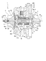
 図1は、この発明の第一実施形態におけるターボチャージャの構成を示す断面図である。図2は、この発明の第一実施形態におけるターボチャージャに設けたスリーブを示す拡大断面図である。
 図1に示すように、ターボチャージャ1は、タービンロータ2、コンプレッサロータ3、回転軸4、転がり軸受5、及びハウジング6を備える。このターボチャージャ1は、回転軸4が水平方向に延在するような姿勢で自動車等に搭載される。ここで、図1に示す鎖線は、回転軸4の中心軸Cを示している。以下の説明において、ターボチャージャ1を自動車等に搭載した状態において上方を向く側を「上方」、下方を向く側を「下方」と称する。
(First embodiment)
FIG. 1 is a cross-sectional view showing the configuration of the turbocharger in the first embodiment of the present invention. FIG. 2 is an enlarged cross-sectional view showing a sleeve provided in the turbocharger according to the first embodiment of the present invention.
As shown in FIG. 1, the turbocharger 1 includes a turbine rotor 2, a compressor rotor 3, a rotating shaft 4, a rolling bearing 5, and a housing 6. The turbocharger 1 is mounted on an automobile or the like in such a posture that the rotating shaft 4 extends in the horizontal direction. Here, the chain line shown in FIG. 1 indicates the central axis C of the rotating shaft 4. In the following description, the side facing upward when the turbocharger 1 is mounted on an automobile or the like is referred to as “upward”, and the side facing downward is referred to as “downward”.
 ターボチャージャ1は、図示しないエンジンから供給される排気ガス流によってタービンロータ2が中心軸Cを中心に回転する。回転軸4及びコンプレッサロータ3は、タービンロータ2の回転に伴って中心軸Cを中心に回転する。コンプレッサロータ3は、回転することによって空気を圧縮する。この圧縮された空気は、図示しないエンジンに供給される。 In the turbocharger 1, the turbine rotor 2 rotates about the central axis C by an exhaust gas flow supplied from an engine (not shown). The rotating shaft 4 and the compressor rotor 3 rotate around the central axis C as the turbine rotor 2 rotates. The compressor rotor 3 compresses air by rotating. This compressed air is supplied to an engine (not shown).
 ハウジング6は、例えば、ブラケット(図示せず)、コンプレッサ、タービン等を介して車体等に支持される。ハウジング6は、その内部に転がり軸受5を収容する収容部61を有している。さらに、ハウジング6は、中心軸Cが延びる方向の一端側に開口部60aを有し、他端側に開口部60bを有している。回転軸4は、収容部61に収容された転がり軸受5によって、中心軸C回りに回転自在に支持されている。この回転軸4の第一端部4a、第二端部4bは、開口部60a、60bを通してハウジング6の外部に突出している。 The housing 6 is supported on the vehicle body via a bracket (not shown), a compressor, a turbine, and the like. The housing 6 has an accommodating portion 61 for accommodating the rolling bearing 5 therein. Furthermore, the housing 6 has an opening 60a on one end side in the direction in which the central axis C extends, and an opening 60b on the other end side. The rotating shaft 4 is rotatably supported around the central axis C by the rolling bearing 5 accommodated in the accommodating portion 61. The first end portion 4a and the second end portion 4b of the rotating shaft 4 project outside the housing 6 through the openings 60a and 60b.
 タービンロータ2とコンプレッサロータ3とは、ハウジング6の一端側と他端側に配設されている。タービンロータ2は、回転軸4の第一端部4aに一体に設けられている。コンプレッサロータ3は、回転軸4の第二端部4bに形成されたネジ部4nとナット31とのネジ作用により、第二端部4bに結合されている。回転軸4、タービンロータ2及びコンプレッサロータ3は、回転軸4と一体に中心軸C回りに回転する。 The turbine rotor 2 and the compressor rotor 3 are disposed on one end side and the other end side of the housing 6. The turbine rotor 2 is provided integrally with the first end portion 4 a of the rotating shaft 4. The compressor rotor 3 is coupled to the second end portion 4 b by the screw action of the screw portion 4 n formed on the second end portion 4 b of the rotating shaft 4 and the nut 31. The rotating shaft 4, the turbine rotor 2, and the compressor rotor 3 rotate around the central axis C together with the rotating shaft 4.
 転がり軸受5は、内輪50と、外輪51と、転動体52と、保持器(図示せず)と、を備えている。
 内輪50は、円筒状に形成されている。この内輪50は、回転軸4の外周面に嵌め込み等により固定されて回転軸4と一体に回転する。
The rolling bearing 5 includes an inner ring 50, an outer ring 51, a rolling element 52, and a cage (not shown).
The inner ring 50 is formed in a cylindrical shape. The inner ring 50 is fixed to the outer peripheral surface of the rotary shaft 4 by being fitted or the like, and rotates integrally with the rotary shaft 4.
 外輪51は、内輪50よりも径が大きな円筒状に形成されている。外輪51は、内輪50の外周側に配されるとともに、内輪50と径方向に間隔を空けて配されている。 The outer ring 51 is formed in a cylindrical shape having a larger diameter than the inner ring 50. The outer ring 51 is disposed on the outer peripheral side of the inner ring 50 and is spaced from the inner ring 50 in the radial direction.
 転動体52は、球状に形成されている。転動体52は、内輪50と外輪51の間に複数設けられている。これら複数の転動体52は、上述した保持器によってそれぞれ周方向に間隔を空けて設けられている。内輪50の外周面には、中心軸Cの延びる軸線方向の両端部に、それぞれ、周方向に連続する軌道溝53が形成されている。同様に、外輪51の内周面には、中心軸C方向の両端部に、各軌道溝53の外周側で対向するように、周方向に連続する軌道溝54が形成されている。複数の転動体52は、転がり軸受5の中心軸Cの延びる軸線方向の両端部のそれぞれにおいて、軌道溝53,54の間に挟み込まれている。これにより、外輪51に対して回転軸4とともに内輪50が回転すると、これら複数の転動体52が内輪50と外輪51との間で転動する。 The rolling element 52 is formed in a spherical shape. A plurality of rolling elements 52 are provided between the inner ring 50 and the outer ring 51. The plurality of rolling elements 52 are provided at intervals in the circumferential direction by the cage described above. On the outer peripheral surface of the inner ring 50, raceway grooves 53 that are continuous in the circumferential direction are formed at both ends in the axial direction in which the central axis C extends. Similarly, on the inner peripheral surface of the outer ring 51, track grooves 54 that are continuous in the circumferential direction are formed at both ends in the direction of the central axis C so as to face each other on the outer periphery side of each track groove 53. The plurality of rolling elements 52 are sandwiched between raceway grooves 53 and 54 at both ends in the axial direction in which the central axis C of the rolling bearing 5 extends. Thereby, when the inner ring 50 rotates together with the rotating shaft 4 with respect to the outer ring 51, the plurality of rolling elements 52 roll between the inner ring 50 and the outer ring 51.
 ハウジング6の内部に形成される収容部61は、中心軸Cの延びる軸線方向から見て断面円形に形成されている。この収容部61は、中心軸Cの延びる軸線方向に連続するように形成されている。この収容部61に転がり軸受5が収容される。
 図1、図2に示すように、収容部61の内側には、スリーブ80Aが嵌め込み等により固定されている。この実施形態におけるスリーブ80Aは、円筒状に形成される場合を例示している。スリーブ80Aは、いわゆる制振合金によって形成することができる。具体的には、スリーブ80Aを形成する制振合金としては、例えば片状黒鉛鋳鉄、アルミニウム・亜鉛(Al-Zn)合金、マグネシウム(Mg)合金、鉄(Fe)13%クロム(Cr)、ニッケル・チタン(Ni-Ti)合金、銅・アルミニウム・ニッケル(Cu-Al-Ni)合金、マンガン・銅(Mn-Cu)合金等を例示できる。
The accommodating part 61 formed inside the housing 6 is formed in a circular cross section when viewed from the axial direction in which the central axis C extends. The accommodating portion 61 is formed so as to be continuous in the axial direction in which the central axis C extends. The rolling bearing 5 is accommodated in the accommodating portion 61.
As shown in FIGS. 1 and 2, a sleeve 80 </ b> A is fixed inside the accommodating portion 61 by fitting or the like. The sleeve 80A in this embodiment is exemplified as being formed in a cylindrical shape. The sleeve 80A can be formed of a so-called damping alloy. Specifically, as the damping alloy for forming the sleeve 80A, for example, flake graphite cast iron, aluminum / zinc (Al—Zn) alloy, magnesium (Mg) alloy, iron (Fe) 13% chromium (Cr), nickel Examples include titanium (Ni—Ti) alloys, copper / aluminum / nickel (Cu—Al—Ni) alloys, and manganese / copper (Mn—Cu) alloys.
 スリーブ80A内には、転がり軸受5の外輪51が挿入されている。スリーブ80Aの内径は、転がり軸受5の外輪51の外径よりも僅かに大きく形成されている。これにより、転がり軸受5の外輪51の外周面と、スリーブ80Aの内周面との間には、隙間Sが形成される。 The outer ring 51 of the rolling bearing 5 is inserted into the sleeve 80A. The inner diameter of the sleeve 80 </ b> A is slightly larger than the outer diameter of the outer ring 51 of the rolling bearing 5. Thereby, a gap S is formed between the outer peripheral surface of the outer ring 51 of the rolling bearing 5 and the inner peripheral surface of the sleeve 80A.
 図1に示すように、収容部61には、タービンロータ2側の端部61aに、スラスト受け部62が形成されている。このスラスト受け部62は、転がり軸受5のタービンロータ2側へのスラスト荷重を受ける。スラスト受け部62は、収容部61の端部61aから半径方向内側に突出している。このスラスト受け部62には、収容部61に収容されたスリーブ80Aと転がり軸受5の外輪51とのタービンロータ2側の各端部が突き当たった状態となる。 As shown in FIG. 1, a thrust receiving portion 62 is formed in the accommodating portion 61 at an end portion 61 a on the turbine rotor 2 side. The thrust receiving portion 62 receives a thrust load on the rolling bearing 5 toward the turbine rotor 2 side. The thrust receiving portion 62 protrudes radially inward from the end portion 61 a of the accommodating portion 61. In the thrust receiving portion 62, the end portions on the turbine rotor 2 side of the sleeve 80A accommodated in the accommodating portion 61 and the outer ring 51 of the rolling bearing 5 are in contact with each other.
 一方で、収容部61には、そのコンプレッサロータ3側の端部61bに、スラスト受け部材63が取り付けられている。このスラスト受け部材63は、転がり軸受5のコンプレッサロータ3側へのスラスト荷重を受ける。スラスト受け部材63は、中央部に開口部64を有した円板状に形成されている。このスラスト受け部材63の開口部64の周縁部には、スリーブ80Aと外輪51とのコンプレッサロータ3側の各端部が突き当たった状態となる。ここで、スラスト受け部62および、スラスト受け部材63は、必要に応じて設ければ良く、省略しても良い。 On the other hand, a thrust receiving member 63 is attached to the end 61b of the accommodating portion 61 on the compressor rotor 3 side. The thrust receiving member 63 receives a thrust load toward the compressor rotor 3 side of the rolling bearing 5. The thrust receiving member 63 is formed in a disk shape having an opening 64 at the center. The end portions of the sleeve 80A and the outer ring 51 on the compressor rotor 3 side are in contact with the peripheral edge portion of the opening 64 of the thrust receiving member 63. Here, the thrust receiving portion 62 and the thrust receiving member 63 may be provided as necessary and may be omitted.
 回転軸4には、転がり軸受5の内輪50に対してタービンロータ2側に、大径部4dが設けられている。大径部4dは、内輪50の内径よりも大きな外径を有している。内輪50は、タービンロータ2側の端部を回転軸4の大径部4dに突き当てた状態で設けられている。
 さらに、回転軸4には、転がり軸受5の内輪50に対してコンプレッサロータ3側に、円筒状のブッシュ45が設けられている。ブッシュ45は、内輪50とコンプレッサロータ3との間に挟み込まれて設けられている。
 このようにして、転がり軸受5の内輪50は、回転軸4の大径部4dと、ブッシュ45との間に挟み込まれて設けられている。
The rotary shaft 4 is provided with a large-diameter portion 4 d on the turbine rotor 2 side with respect to the inner ring 50 of the rolling bearing 5. The large diameter portion 4 d has an outer diameter larger than the inner diameter of the inner ring 50. The inner ring 50 is provided in a state in which the end portion on the turbine rotor 2 side is abutted against the large diameter portion 4 d of the rotating shaft 4.
Further, the rotary shaft 4 is provided with a cylindrical bush 45 on the compressor rotor 3 side with respect to the inner ring 50 of the rolling bearing 5. The bush 45 is provided between the inner ring 50 and the compressor rotor 3.
Thus, the inner ring 50 of the rolling bearing 5 is provided so as to be sandwiched between the large-diameter portion 4d of the rotating shaft 4 and the bush 45.
 ハウジング6の開口部6bには、開口部60bを閉塞するプレート65が設けられている。プレート65は、中央部に開口部65aを有した円板状に形成されている。プレート65の外周部には、中心軸Cの延びる軸線方向のスラスト受け部材63側に延びる周壁部65bが一体に形成されている。プレート65は、開口部65aにブッシュ45が挿入されるとともに、周壁部65bをスラスト受け部材63に突き当てた状態で設けられる。 A plate 65 that closes the opening 60 b is provided in the opening 6 b of the housing 6. The plate 65 is formed in a disc shape having an opening 65a at the center. A peripheral wall portion 65b extending toward the thrust receiving member 63 in the axial direction in which the central axis C extends is integrally formed on the outer peripheral portion of the plate 65. The plate 65 is provided in a state where the bush 45 is inserted into the opening 65 a and the peripheral wall 65 b is abutted against the thrust receiving member 63.
 さらに、ハウジング6には、転がり軸受5を潤滑油により潤滑するため、以下のような構成を有している。
 ハウジング6には、外周面6fからハウジング6の径方向内方に向かって延びる給油管接続口71が形成されている。この給油管接続口71には、潤滑油を供給する潤滑油供給管(図示せず)が接続される。
 給油管接続口71の先端部と、収容部61との間には、複数の供給流路72が形成されている。供給流路72は、転がり軸受5の両端部にそれぞれ設けられた転動体52よりも内側に開口している。
Further, the housing 6 has the following configuration in order to lubricate the rolling bearing 5 with lubricating oil.
In the housing 6, an oil supply pipe connection port 71 extending from the outer peripheral surface 6 f toward the radially inner side of the housing 6 is formed. A lubricating oil supply pipe (not shown) that supplies lubricating oil is connected to the oil supply pipe connection port 71.
A plurality of supply flow paths 72 are formed between the distal end portion of the oil supply pipe connection port 71 and the accommodating portion 61. The supply flow path 72 opens to the inner side of the rolling elements 52 provided at both ends of the rolling bearing 5.
 さらに、収容部61に収容されたスリーブ80A、転がり軸受5の外輪51には、収容部61の内面に開口した供給流路72に対向する位置に、それそれ、スリーブ80A、外輪51を径方向、言い換えれば厚さ方向に貫通する潤滑油導入孔73、74が形成されている。 Further, the sleeve 80A accommodated in the accommodating portion 61 and the outer ring 51 of the rolling bearing 5 are arranged so that the sleeve 80A and the outer ring 51 are radially arranged at positions facing the supply flow path 72 opened on the inner surface of the accommodating portion 61. In other words, lubricating oil introduction holes 73 and 74 penetrating in the thickness direction are formed.
 さらに、転がり軸受5の外輪51、スリーブ80A、収容部61には、それぞれの最下端部に、下方に向かって貫通する排出流路75、76、77が形成されている。 Further, the outer ring 51, the sleeve 80A, and the accommodating portion 61 of the rolling bearing 5 are formed with discharge passages 75, 76, 77 penetrating downward at the lowest end portions thereof.
 ハウジング6は、収容部61の下方に、排油室78を備えている。排油室78の上部に、上記の排出流路75、76、77が開口している。また、ハウジング6には、排油室78の下端部と、ハウジング6の最下部における外周面6fとを貫通する排油口79が形成されている。 The housing 6 includes an oil discharge chamber 78 below the accommodating portion 61. In the upper part of the oil discharge chamber 78, the discharge flow paths 75, 76, 77 are opened. Further, the housing 6 is formed with an oil discharge port 79 that penetrates the lower end portion of the oil discharge chamber 78 and the outer peripheral surface 6 f at the lowermost portion of the housing 6.
 まず、給油管接続口71に接続された潤滑油供給管(図示せず)から潤滑油が送り込まれると、潤滑油は、給油管接続口71の先端部から供給流路72を通り、収容部61内に送り込まれる。収容部61内に送り込まれた潤滑油は、さらに潤滑油導入孔73,74を通り、外輪51の内側に送り込まれる。これにより、転がり軸受5の内輪50と外輪51との間に潤滑油が供給され、転動体52が潤滑される。 First, when lubricating oil is fed from a lubricating oil supply pipe (not shown) connected to the oil supply pipe connection port 71, the lubricating oil passes through the supply flow path 72 from the distal end portion of the oil supply pipe connection port 71, and the accommodating portion 61 is fed into. The lubricating oil sent into the accommodating portion 61 is further sent into the outer ring 51 through the lubricating oil introduction holes 73 and 74. Thereby, lubricating oil is supplied between the inner ring | wheel 50 and the outer ring | wheel 51 of the rolling bearing 5, and the rolling element 52 is lubricated.
 スリーブ80Aに形成された潤滑油導入孔73を通過した潤滑油の一部は、スリーブ80Aと外輪51との隙間S(図2参照)に流れ込む。これによって、スリーブ80Aと外輪51との間に油膜Mが形成される。 Part of the lubricating oil that has passed through the lubricating oil introduction hole 73 formed in the sleeve 80A flows into the gap S (see FIG. 2) between the sleeve 80A and the outer ring 51. As a result, an oil film M is formed between the sleeve 80 </ b> A and the outer ring 51.
 転がり軸受5の外輪51と内輪50との間に送り込まれた潤滑油は、外輪51に形成された排出流路75、スリーブ80Aに形成された排出流路76、収容部61に形成された排出流路77を通り、排油室78に排出される。
 スリーブ80Aと外輪51との隙間S(図2参照)に送り込まれた潤滑油は、排出流路75、76の周縁部から排出流路76、77に流れ出し、排油室78に排出される。
 排油室78の潤滑油は、排油口79を通してハウジング6の外部に排出される。
The lubricating oil fed between the outer ring 51 and the inner ring 50 of the rolling bearing 5 is discharged from the discharge passage 75 formed in the outer ring 51, the discharge passage 76 formed in the sleeve 80A, and the discharge formed in the housing portion 61. It passes through the flow path 77 and is discharged into the oil discharge chamber 78.
Lubricating oil fed into the gap S (see FIG. 2) between the sleeve 80 </ b> A and the outer ring 51 flows out from the peripheral portions of the discharge passages 75, 76 to the discharge passages 76, 77 and is discharged into the oil discharge chamber 78.
The lubricating oil in the oil discharge chamber 78 is discharged to the outside of the housing 6 through the oil discharge port 79.
 上述した第一実施形態では、転がり軸受5の外輪51の外周側に、油膜Mが形成される隙間Sを隔てて、制振材料からなるスリーブ80Aを設けるようにした。これによって、ターボチャージャ1の作動時に、回転軸4の回転にともなって転がり軸受5等で発生する騒音や振動を、油膜Mおよびスリーブ80Aで減衰することができる。これにより、騒音や振動がハウジング6を介してターボチャージャ1の外部に伝わることを抑制できる。その結果、ターボチャージャ1の作動時における騒音や振動を、より一層低減することが可能となる。 In the first embodiment described above, the sleeve 80A made of a damping material is provided on the outer peripheral side of the outer ring 51 of the rolling bearing 5 with a gap S in which the oil film M is formed. As a result, when the turbocharger 1 is operated, noise and vibration generated in the rolling bearing 5 and the like as the rotating shaft 4 rotates can be attenuated by the oil film M and the sleeve 80A. Thereby, it is possible to suppress noise and vibration from being transmitted to the outside of the turbocharger 1 through the housing 6. As a result, noise and vibration during the operation of the turbocharger 1 can be further reduced.
(第二実施形態)
 次に、この発明にかかるターボチャージャの第二実施形態について説明する。この第二実施形態で示すターボチャージャは、第一実施形態のターボチャージャに対して、転がり軸受5の外輪51の外周側に設けたスリーブ80Bが異なるのみである。したがって、第二実施形態の説明においては、第一実施形態と同一部分に同一符号を付して説明するとともに重複説明を省略する。つまり、第一実施形態で説明した構成と共通するターボチャージャ1の全体構成については、その説明を省略する。
(Second embodiment)
Next, a second embodiment of the turbocharger according to the present invention will be described. The turbocharger shown in the second embodiment is different from the turbocharger of the first embodiment only in the sleeve 80B provided on the outer peripheral side of the outer ring 51 of the rolling bearing 5. Therefore, in the description of the second embodiment, the same portions as those in the first embodiment are denoted by the same reference numerals and redundant description is omitted. That is, the description of the overall configuration of the turbocharger 1 common to the configuration described in the first embodiment is omitted.
 図3は、この発明の第二実施形態におけるターボチャージャの構成を示す断面図である。図4は、この発明の第二実施形態におけるターボチャージャに設けたスリーブを示す拡大断面図である。
 図3に示すように、収容部61の内側には、円筒状のスリーブ80Bが嵌入されている。
 このスリーブ80Bは、内周側に設けられた第一スリーブ81と、第一スリーブ81の外周側に設けられた第二スリーブ82と、を備えた二重構造をなしている。
FIG. 3 is a cross-sectional view showing the configuration of the turbocharger in the second embodiment of the present invention. FIG. 4 is an enlarged sectional view showing a sleeve provided in the turbocharger according to the second embodiment of the present invention.
As shown in FIG. 3, a cylindrical sleeve 80 </ b> B is fitted inside the accommodating portion 61.
The sleeve 80B has a double structure including a first sleeve 81 provided on the inner peripheral side and a second sleeve 82 provided on the outer peripheral side of the first sleeve 81.
 第一スリーブ81は、転がり軸受5の外輪を支持する必要があることから、第二スリーブ82よりも剛性の高い材料となる組み合わせで形成する。第一スリーブ81は、例えば金属材料で形成することができる。ここで、第一スリーブ81は、制振材料ではない金属材料で形成してもよいが、金属系の制振材料で形成すれば、スリーブ80Bにおける制震性能がさらに高まる。このような制振材料としては、上記第一実施形態におけるスリーブ80Aと同様、例えば片状黒鉛鋳鉄、アルミニウム・亜鉛(Al-Zn)合金、マグネシウム(Mg)合金、鉄(Fe)13%クロム(Cr)、ニッケル・チタン(Ni-Ti)合金、銅・アルミニウム・ニッケル(Cu-Al-Ni)合金、マンガン・銅(Mn-Cu)合金等の制振合金を例示できる。 Since the first sleeve 81 needs to support the outer ring of the rolling bearing 5, the first sleeve 81 is formed of a combination that is a material having higher rigidity than the second sleeve 82. The first sleeve 81 can be formed of, for example, a metal material. Here, the first sleeve 81 may be formed of a metal material that is not a vibration damping material. However, if the first sleeve 81 is formed of a metal vibration damping material, the vibration damping performance of the sleeve 80B is further enhanced. As such a vibration damping material, for example, flake graphite cast iron, aluminum / zinc (Al—Zn) alloy, magnesium (Mg) alloy, iron (Fe) 13% chromium (like the sleeve 80A in the first embodiment) Cr), nickel-titanium (Ni-Ti) alloy, copper-aluminum-nickel (Cu-Al-Ni) alloy, manganese-copper (Mn-Cu) alloy, and the like.
 第二スリーブ82は、制振材料から形成されている。第二スリーブ82を形成する制振材料としては、例えば、ポリエーテルエーテルケトン(PEEK)、ポリフェニレンサルファイド(PPS)、ポリテトラフロロエチレン(PTFE)、ポリエーテルスルホン(PES)、ポリアミドイミド(PAI)、ポリプロメリトイミド(芳香族ポリイミドPI)、ポリアリレート(芳香族ポリエステル)、ポリメタフェニレン、フッ素系樹脂等の樹脂材料を例示できる。
 第二スリーブ82は、上記した以外にも、ゴム系材料、セラミック系材料等の制振材料で形成しても良い。
The second sleeve 82 is made of a vibration damping material. Examples of the vibration damping material forming the second sleeve 82 include polyether ether ketone (PEEK), polyphenylene sulfide (PPS), polytetrafluoroethylene (PTFE), polyether sulfone (PES), polyamideimide (PAI), Examples thereof include resin materials such as polypromelitoimide (aromatic polyimide PI), polyarylate (aromatic polyester), polymetaphenylene, and fluorine-based resin.
In addition to the above, the second sleeve 82 may be formed of a vibration damping material such as a rubber material or a ceramic material.
 上述した第二スリーブ82は、上記第一スリーブ81として示した制振合金のうち、第一スリーブ81とは異なる制振合金で形成しても良い。
 ターボチャージャ1の作動時、ハウジング6内は高温となる。そのため、第一スリーブ81および第二スリーブ82は、ターボチャージャ作動時のハウジング内温度に対する耐熱性を有した材料で形成するのが好ましい。
The second sleeve 82 described above may be formed of a damping alloy different from the first sleeve 81 among the damping alloys shown as the first sleeve 81.
During operation of the turbocharger 1, the inside of the housing 6 becomes hot. Therefore, the first sleeve 81 and the second sleeve 82 are preferably formed of a material having heat resistance against the temperature in the housing when the turbocharger is operated.
 ここで、第二スリーブ82の制振材料として例示した樹脂材料の連続使用可能温度の上限は、ポリエーテルエーテルケトンが240℃、ポリフェニレンサルファイド(PPS)が220℃である。さらに、ポリテトラフロロエチレン(PTFE)が260℃、ポリエーテルスルホン(PES)が180℃、ポリアミドイミド(PAI)が210℃である。さらに、ポリプロメリトイミド(芳香族ポリイミドPI)が300℃、ポリアリレート(芳香族ポリエステル)が300℃、ポリメタフェニレンが220℃、フッ素系樹脂が250℃である。 Here, the upper limit of the continuous usable temperature of the resin material exemplified as the vibration damping material of the second sleeve 82 is 240 ° C. for polyetheretherketone and 220 ° C. for polyphenylene sulfide (PPS). Furthermore, polytetrafluoroethylene (PTFE) is 260 ° C, polyethersulfone (PES) is 180 ° C, and polyamideimide (PAI) is 210 ° C. Furthermore, polypromellitic imide (aromatic polyimide PI) is 300 ° C., polyarylate (aromatic polyester) is 300 ° C., polymetaphenylene is 220 ° C., and fluororesin is 250 ° C.
 上述した第二実施形態では、上記第一実施形態と同様、転がり軸受5の外輪51の外周側に、油膜Mが形成される隙間Sを隔てて、制振材料からなるスリーブ80Bを設けるようにした。これによって、ターボチャージャ1の作動時に、回転軸4の回転にともなって転がり軸受5等で発生する騒音や振動を、油膜Mおよびスリーブ80Bで減衰することができる。これにより、騒音や振動がハウジング6を介してターボチャージャ1の外部に伝わるのを抑えることができる。その結果、ターボチャージャ1の作動時における騒音や振動を、より一層低減することが可能となる。 In the second embodiment described above, as in the first embodiment, a sleeve 80B made of a damping material is provided on the outer peripheral side of the outer ring 51 of the rolling bearing 5 with a gap S in which the oil film M is formed. did. As a result, when the turbocharger 1 is operated, noise and vibration generated in the rolling bearing 5 and the like as the rotating shaft 4 rotates can be attenuated by the oil film M and the sleeve 80B. Thereby, it is possible to suppress noise and vibration from being transmitted to the outside of the turbocharger 1 through the housing 6. As a result, noise and vibration during the operation of the turbocharger 1 can be further reduced.
 さらに、スリーブ80Bは、内周側の第一スリーブ81と、外周側の第二スリーブ82とからなる二重構造となっている。これに加えて、第一スリーブ81を第二スリーブ82よりも剛性の高い材料で形成している。そのため、第一スリーブ81によって転がり軸受5を強固に支持しつつ、より軟らかい第二スリーブ82によって制振性能を発揮することができる。
 さらに、第一スリーブ81と第二スリーブ82とを、互いに異なる制振材料で形成すれば、より効果的に制振性能を発揮することもできる。
Furthermore, the sleeve 80B has a double structure including a first sleeve 81 on the inner peripheral side and a second sleeve 82 on the outer peripheral side. In addition to this, the first sleeve 81 is formed of a material having higher rigidity than the second sleeve 82. Therefore, while the rolling bearing 5 is firmly supported by the first sleeve 81, the vibration damping performance can be exhibited by the softer second sleeve 82.
Furthermore, if the first sleeve 81 and the second sleeve 82 are formed of different damping materials, the damping performance can be exhibited more effectively.
 上記第二実施形態で示した第一スリーブ81を形成する材料と、第二スリーブ82を形成する材料とを、入れ替えてスリーブ80Bを形成することもできる。 The material for forming the first sleeve 81 and the material for forming the second sleeve 82 shown in the second embodiment can be interchanged to form the sleeve 80B.
(その他の実施形態)
 この発明は、上述した実施形態に限定されるものではなく、この発明の趣旨を逸脱しない範囲において、設計変更可能である。
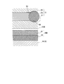
 例えば、上記第二実施形態では、スリーブ80Bを構成する第一スリーブ81と第二スリーブ82とを二重に備えるようにしたが、一つのスリーブにおいて、内周面側の層と外周面側の層とを備えた二層構造として、それぞれの層を異なる材料から形成するようにしてもよい。例えば、金属製の筒体の内周面または外周面に、上記実施形態で示したような制振材料からなる制振層を一体に形成するようにしてもよい。
(Other embodiments)
The present invention is not limited to the above-described embodiment, and design changes can be made without departing from the spirit of the present invention.
For example, in the second embodiment, the first sleeve 81 and the second sleeve 82 constituting the sleeve 80B are provided twice. However, in one sleeve, the inner peripheral surface side layer and the outer peripheral surface side layer are provided. As a two-layer structure including layers, each layer may be formed of different materials. For example, a damping layer made of a damping material as shown in the above embodiment may be integrally formed on the inner or outer peripheral surface of a metal cylinder.
 上述した各実施形態において、スリーブ80A,80Bを円筒状としたが、これに限らない。図5~図8は、上記第一及び第二実施形態で示したスリーブ80A,80Bの変形例における外観を示す図である。
 図5に示すように、スリーブ80A,80Bを、転がり軸受5の外輪51における中心軸C方向の長さよりも短く形成し、このようなスリーブ80A,80Bを、中心軸C方向に沿って間隔を空けて複数設けるようにしても良い。
In each embodiment mentioned above, sleeve 80A, 80B was made into cylindrical shape, However, It is not restricted to this. FIGS. 5 to 8 are views showing the external appearances of the modified examples of the sleeves 80A and 80B shown in the first and second embodiments.
As shown in FIG. 5, the sleeves 80A and 80B are formed to be shorter than the length of the outer ring 51 of the rolling bearing 5 in the direction of the central axis C, and the sleeves 80A and 80B are spaced along the direction of the central axis C. A plurality of them may be provided.
 また、図6に示すように、スリーブ80A,80Bを、周方向に分割した複数の分割子85からなるようにしてもよい。さらに、このような分割子85は、周方向に間隔を空けて複数設けるようにしてもよい。 Further, as shown in FIG. 6, the sleeves 80A and 80B may include a plurality of dividers 85 divided in the circumferential direction. Further, a plurality of such dividers 85 may be provided at intervals in the circumferential direction.
 さらに、図7に示すように、スリーブ80A,80Bの外周面に、中心軸C方向に連続する突条86を周方向に複数備えたスプライン形状等としても良い。さらに、ハウジング6の収容部61の内面にスリーブ80A,80Bのスプライン形状の突条86に対応する凹部(図示せず)を形成してもよい。このようにすることで、突条86が凹部に嵌り込み、収容部61に対してスリーブ80A,80Bの周方向の位置決めをすることができる。そのため、排出流路76の位置決めを容易に行うことができる。ここで、図7ではスプライン形状を例示したが、収容部61に対してスリーブ80A,80Bの周方向の変位を抑制できる形状であればスプライン形状に限られない。また、突条86の形成される数は、複数に限られない。 Furthermore, as shown in FIG. 7, it is good also as a spline shape etc. which provided the protrusion 86 continuous in the center axis C direction on the outer peripheral surface of sleeve 80A, 80B in the circumferential direction. Furthermore, you may form the recessed part (not shown) corresponding to the spline-shaped protrusion 86 of sleeve 80A, 80B in the inner surface of the accommodating part 61 of the housing 6. FIG. By doing in this way, the protrusion 86 fits into the recess, and the sleeves 80 </ b> A and 80 </ b> B can be positioned in the circumferential direction with respect to the accommodating portion 61. Therefore, the discharge channel 76 can be easily positioned. Here, although the spline shape is illustrated in FIG. 7, the shape is not limited to the spline shape as long as the displacement of the sleeves 80 </ b> A and 80 </ b> B in the circumferential direction can be suppressed with respect to the accommodating portion 61. Further, the number of protrusions 86 formed is not limited to a plurality.
 さらに、図8に示すように、スリーブ80A,80Bを、中心軸C回りの周方向に連続する凹凸87を中心軸C方向に連続して形成した、いわゆる蛇腹状とすることもできる。
 このような形状とすることでも、スリーブ80A,80Bと、その外周側の収容部61との接触面積を小さくすることができ、振動や騒音が伝わりにくくなる。
Further, as shown in FIG. 8, the sleeves 80 </ b> A and 80 </ b> B can be formed in a so-called bellows shape in which the unevenness 87 continuous in the circumferential direction around the central axis C is continuously formed in the central axis C direction.
Even with such a shape, the contact area between the sleeves 80A and 80B and the accommodating portion 61 on the outer peripheral side can be reduced, and vibration and noise are hardly transmitted.
 さらに、例えば、転がり軸受5の外輪51と、スリーブ80A,80Bとの間に、油膜Mを保持するためのO-リング等を設けてもよい。このようなO-リングは、外輪51とスリーブ80Aの中心軸C方向両端部にそれぞれ設けられる。 Furthermore, for example, an O-ring for holding the oil film M may be provided between the outer ring 51 of the rolling bearing 5 and the sleeves 80A and 80B. Such O-rings are provided at both ends of the outer ring 51 and the sleeve 80A in the central axis C direction.
 さらに、転がり軸受5の構成は、上記実施形態で示したものに限らず、適宜他の構成とすることができる。
 さらに、上記実施形態では、転がり軸受5を例えば1つだけ備えた構成となっているが、これに限るものではなく、例えば複数の転がり軸受を回転軸4の中心軸方向に直列に並んで備える構成であってもよい。
 さらに、ターボチャージャ1の構成も、上記実施形態で示した構成に限らず、適宜他の構成とすることができる。
Furthermore, the configuration of the rolling bearing 5 is not limited to that shown in the above embodiment, and other configurations can be appropriately employed.
Furthermore, in the said embodiment, although it becomes the structure provided with only one rolling bearing 5, for example, it is not restricted to this, For example, a several rolling bearing is arranged in series in the center axis direction of the rotating shaft 4. It may be a configuration.
Furthermore, the configuration of the turbocharger 1 is not limited to the configuration shown in the above embodiment, and other configurations can be appropriately employed.
 制振材料からなるスリーブを、転がり軸受の外周側に、油膜が形成される隙間を隔てて設けることで、ターボチャージャの作動時における騒音や振動をより一層低減することができる。 The noise and vibration during the operation of the turbocharger can be further reduced by providing the sleeve made of a damping material on the outer peripheral side of the rolling bearing with a gap where an oil film is formed.
1 ターボチャージャ
2 タービンロータ
3 コンプレッサロータ
4 回転軸
4a 第一端部
4b 第二端部
4d 大径部
4n ネジ部
5 転がり軸受
6 ハウジング
6a、6b 開口部
6f 外周面
31 ナット
45 ブッシュ
50 内輪
51 外輪
52 転動体
53,54 軌道溝
60a 開口部
61 収容部
61a 端部
61b 端部
62 スラスト受け部
63 スラスト受け部材
64 開口部
65 プレート
65a 開口部
65b 周壁部
71 給油管接続口
72 供給流路
73,74 潤滑油導入孔
75 排出流路
76 排出流路
77 排出流路
78 排油室
79 排油口
80A,80B スリーブ
80a 一端
80b 他端
81 第一スリーブ
82 第二スリーブ
85 分割子
86 突条
87 凹凸
C 中心軸
M 油膜
S 隙間
DESCRIPTION OF SYMBOLS 1 Turbocharger 2 Turbine rotor 3 Compressor rotor 4 Rotating shaft 4a 1st end part 4b 2nd end part 4d Large diameter part 4n Screw part 5 Rolling bearing 6 Housing 6a, 6b Opening part 6f Outer peripheral surface 31 Nut 45 Bush 50 Inner ring 51 Outer ring 52 Rolling elements 53, 54 Track groove 60 a Opening part 61 Housing part 61 a End part 61 b End part 62 Thrust receiving part 63 Thrust receiving member 64 Opening part 65 Plate 65 a Opening part 65 b Perimeter wall part 71 Oil supply pipe connection port 72 Supply flow path 73, 74 Lubricating oil introduction hole 75 Discharge flow path 76 Discharge flow path 77 Discharge flow path 78 Oil discharge chamber 79 Oil discharge port 80A, 80B Sleeve 80a One end 80b Other end 81 First sleeve 82 Second sleeve 85 Divider 86 Projection 87 Concavity and convexity C Center axis M Oil film S Clearance

Claims (5)

  1.  軸線に沿って延びる回転軸と、
     前記回転軸の一端側に設けられたタービンロータと、
     前記回転軸の他端側に設けられたコンプレッサロータと、
     前記タービンロータと前記コンプレッサロータとの間で、前記回転軸を前記軸線回りに回転可能に支持する転がり軸受と、
     前記転がり軸受を外周側から覆うハウジングと、
     前記ハウジング内に設けられ、前記転がり軸受の外輪の外周側に、前記外輪との間で潤滑油を保持する隙間を隔てて配された、少なくとも一部が制振材料からなるスリーブと、
    を備えるターボチャージャ。
    A rotation axis extending along the axis;
    A turbine rotor provided on one end side of the rotating shaft;
    A compressor rotor provided on the other end of the rotating shaft;
    Between the turbine rotor and the compressor rotor, a rolling bearing that rotatably supports the rotating shaft around the axis line;
    A housing covering the rolling bearing from the outer peripheral side;
    A sleeve provided in the housing and disposed on the outer peripheral side of the outer ring of the rolling bearing with a gap holding the lubricating oil between the outer ring and at least a part made of a damping material;
    Turbocharger with
  2.  前記スリーブは、内周側に配置された第一スリーブと、前記第一スリーブの外周側に配置された第二スリーブと、を備える請求項1に記載のターボチャージャ。 The turbocharger according to claim 1, wherein the sleeve includes a first sleeve disposed on an inner peripheral side and a second sleeve disposed on an outer peripheral side of the first sleeve.
  3.  前記第一スリーブと前記第二スリーブとは、互いに異なる制振材料から形成されている請求項2に記載のターボチャージャ。 The turbocharger according to claim 2, wherein the first sleeve and the second sleeve are formed of different damping materials.
  4.  前記第一スリーブおよび前記第二スリーブの一方が金属材料からなり、前記第一スリーブおよび前記第二スリーブの他方が制振材料から形成されている請求項2または3に記載のターボチャージャ。 4. The turbocharger according to claim 2, wherein one of the first sleeve and the second sleeve is made of a metal material, and the other of the first sleeve and the second sleeve is made of a vibration damping material.
  5.  前記第一スリーブは、前記第二スリーブよりも剛性の高い材料で形成されている請求項2から4の何れか一項に記載のターボチャージャ。 The turbocharger according to any one of claims 2 to 4, wherein the first sleeve is formed of a material having higher rigidity than the second sleeve.
PCT/JP2015/061569 2015-04-15 2015-04-15 Turbocharger WO2016166832A1 (en)

Priority Applications (5)

Application Number Priority Date Filing Date Title
US15/565,496 US10539074B2 (en) 2015-04-15 2015-04-15 Turbocharger
PCT/JP2015/061569 WO2016166832A1 (en) 2015-04-15 2015-04-15 Turbocharger
JP2017512116A JP6508490B2 (en) 2015-04-15 2015-04-15 Turbocharger
EP15889170.5A EP3284926B1 (en) 2015-04-15 2015-04-15 Turbocharger
CN201580078742.9A CN107429607B (en) 2015-04-15 2015-04-15 Turbocharger

Applications Claiming Priority (1)

Application Number Priority Date Filing Date Title
PCT/JP2015/061569 WO2016166832A1 (en) 2015-04-15 2015-04-15 Turbocharger

Publications (1)

Publication Number Publication Date
WO2016166832A1 true WO2016166832A1 (en) 2016-10-20

Family

ID=57126628

Family Applications (1)

Application Number Title Priority Date Filing Date
PCT/JP2015/061569 WO2016166832A1 (en) 2015-04-15 2015-04-15 Turbocharger

Country Status (5)

Country Link
US (1) US10539074B2 (en)
EP (1) EP3284926B1 (en)
JP (1) JP6508490B2 (en)
CN (1) CN107429607B (en)
WO (1) WO2016166832A1 (en)

Cited By (1)

* Cited by examiner, † Cited by third party
Publication number Priority date Publication date Assignee Title
US11719124B2 (en) 2019-02-21 2023-08-08 Mitsubishi Heavy Industries Engine & Turbocharger, Ltd. Turbocharger

Families Citing this family (4)

* Cited by examiner, † Cited by third party
Publication number Priority date Publication date Assignee Title
JP6510096B1 (en) * 2018-02-08 2019-05-08 三菱重工業株式会社 Turbocharger
WO2019213202A1 (en) * 2018-05-02 2019-11-07 Borgwarner Inc. Bearing unit
US11021998B2 (en) * 2019-08-08 2021-06-01 General Electric Company Shape memory alloy sleeve support assembly for a bearing
US11572825B1 (en) * 2021-12-29 2023-02-07 Garrett Transportation I Inc. Turbocharger flexible bearing cartridge assembly

Citations (2)

* Cited by examiner, † Cited by third party
Publication number Priority date Publication date Assignee Title
JPH0571358A (en) * 1991-09-09 1993-03-23 Aisin Seiki Co Ltd Bearing device of turbocharger
JPH0710037Y2 (en) * 1988-05-02 1995-03-08 日産自動車株式会社 Supercharger bearing device

Family Cites Families (12)

* Cited by examiner, † Cited by third party
Publication number Priority date Publication date Assignee Title
DE4230037A1 (en) 1991-09-09 1993-03-11 Aisin Seiki CENTRIFUGAL RECHARGE BLOWER
KR100600668B1 (en) * 2004-10-18 2006-07-13 한국과학기술연구원 Air foil bearing having a porous foil
JP2009270612A (en) 2008-05-07 2009-11-19 Toyota Motor Corp Bearing structure of turbocharger
CN102388209B (en) 2009-04-20 2015-06-17 博格华纳公司 Insulating and damping sleeve for a rolling element bearing cartridge
JP2011137395A (en) 2009-12-28 2011-07-14 Jtekt Corp Bearing device for turbocharger
DE102010004870A1 (en) * 2010-01-18 2011-07-21 Bosch Mahle Turbo Systems GmbH & Co. KG, 70376 Pivot bearing arrangement for rotor of turbocharger, has inner ring and outer ring between rotor and housing body, particularly between rotor shaft and housing body of turbocharger
DE102011007250A1 (en) * 2011-04-13 2012-10-18 Schaeffler Technologies AG & Co. KG Turbocharger cartridge with plain bearing supported rolling bearing
EP2743461A1 (en) * 2011-08-30 2014-06-18 Aktiebolaget SKF Turbocharger bearing comprising an insulating sleeve between the inner bearing ring and the shaft
US8911202B2 (en) * 2011-09-20 2014-12-16 Honeywell International Inc. Turbocharger rotating assembly
JP5919745B2 (en) * 2011-11-15 2016-05-18 株式会社島津製作所 Vacuum pump
JP5510592B2 (en) 2013-06-05 2014-06-04 トヨタ自動車株式会社 Bearing device
DE102014200743A1 (en) * 2014-01-16 2015-07-16 Bosch Mahle Turbo Systems Gmbh & Co. Kg turbocharger

Patent Citations (2)

* Cited by examiner, † Cited by third party
Publication number Priority date Publication date Assignee Title
JPH0710037Y2 (en) * 1988-05-02 1995-03-08 日産自動車株式会社 Supercharger bearing device
JPH0571358A (en) * 1991-09-09 1993-03-23 Aisin Seiki Co Ltd Bearing device of turbocharger

Cited By (1)

* Cited by examiner, † Cited by third party
Publication number Priority date Publication date Assignee Title
US11719124B2 (en) 2019-02-21 2023-08-08 Mitsubishi Heavy Industries Engine & Turbocharger, Ltd. Turbocharger

Also Published As

Publication number Publication date
EP3284926A4 (en) 2018-12-05
CN107429607B (en) 2019-12-03
JPWO2016166832A1 (en) 2018-02-08
EP3284926B1 (en) 2020-01-15
CN107429607A (en) 2017-12-01
US20180073433A1 (en) 2018-03-15
US10539074B2 (en) 2020-01-21
JP6508490B2 (en) 2019-05-08
EP3284926A1 (en) 2018-02-21

Similar Documents

Publication Publication Date Title
WO2016166832A1 (en) Turbocharger
US8628247B2 (en) Bearing structure of turbocharger
JP5529714B2 (en) Electric supercharger rotating shaft support structure
US9739310B2 (en) Tilt pad bearing with through-pivot lubrication
JP2009079628A (en) Rolling bearing device and turbocharger using the same
AU2008208471B2 (en) Rotary compressor
US10415644B2 (en) Rotary machine
JP6410006B2 (en) Tilting pad bearing and turbo compressor
JP6079057B2 (en) Rolling bearing device for turbocharger
JP2007071356A (en) Turbocharger rotation supporting device
JP2008008412A (en) Journal bearing unit
JP2014125921A (en) Ball bearing unit for turbocharger
JP6728907B2 (en) Rolling bearing
JP5569114B2 (en) Turbocharger
WO2017082205A1 (en) Roller bearing for very low temperature environments
JP6536417B2 (en) Turbocharger
JP6074966B2 (en) Bearing device
WO2017043425A1 (en) Rolling bearing
JP2009063095A (en) Rolling bearing
JP6403593B2 (en) Journal bearing and rotating machine
JP2020133831A5 (en)
WO2021166180A1 (en) Turbocharger
JP4259208B2 (en) Rolling bearing device
JP2017223317A (en) Bearing mechanism for turbocharger
WO2020067119A1 (en) Ball bearing with pressure-resistant seal

Legal Events

Date Code Title Description
121 Ep: the epo has been informed by wipo that ep was designated in this application

Ref document number: 15889170

Country of ref document: EP

Kind code of ref document: A1

REEP Request for entry into the european phase

Ref document number: 2015889170

Country of ref document: EP

WWE Wipo information: entry into national phase

Ref document number: 15565496

Country of ref document: US

ENP Entry into the national phase

Ref document number: 2017512116

Country of ref document: JP

Kind code of ref document: A

NENP Non-entry into the national phase

Ref country code: DE