WO2016166831A1 - Device for assisting in release of molded product - Google Patents
Device for assisting in release of molded product Download PDFInfo
- Publication number
- WO2016166831A1 WO2016166831A1 PCT/JP2015/061568 JP2015061568W WO2016166831A1 WO 2016166831 A1 WO2016166831 A1 WO 2016166831A1 JP 2015061568 W JP2015061568 W JP 2015061568W WO 2016166831 A1 WO2016166831 A1 WO 2016166831A1
- Authority
- WO
- WIPO (PCT)
- Prior art keywords
- pin member
- cylindrical
- horizontal
- rod
- hole
- Prior art date
Links
Images


Classifications
-
- B—PERFORMING OPERATIONS; TRANSPORTING
- B29—WORKING OF PLASTICS; WORKING OF SUBSTANCES IN A PLASTIC STATE IN GENERAL
- B29C—SHAPING OR JOINING OF PLASTICS; SHAPING OF MATERIAL IN A PLASTIC STATE, NOT OTHERWISE PROVIDED FOR; AFTER-TREATMENT OF THE SHAPED PRODUCTS, e.g. REPAIRING
- B29C45/00—Injection moulding, i.e. forcing the required volume of moulding material through a nozzle into a closed mould; Apparatus therefor
- B29C45/17—Component parts, details or accessories; Auxiliary operations
- B29C45/26—Moulds
- B29C45/33—Moulds having transversely, e.g. radially, movable mould parts
-
- B—PERFORMING OPERATIONS; TRANSPORTING
- B29—WORKING OF PLASTICS; WORKING OF SUBSTANCES IN A PLASTIC STATE IN GENERAL
- B29C—SHAPING OR JOINING OF PLASTICS; SHAPING OF MATERIAL IN A PLASTIC STATE, NOT OTHERWISE PROVIDED FOR; AFTER-TREATMENT OF THE SHAPED PRODUCTS, e.g. REPAIRING
- B29C45/00—Injection moulding, i.e. forcing the required volume of moulding material through a nozzle into a closed mould; Apparatus therefor
- B29C45/17—Component parts, details or accessories; Auxiliary operations
- B29C45/40—Removing or ejecting moulded articles
- B29C45/44—Removing or ejecting moulded articles for undercut articles
-
- B—PERFORMING OPERATIONS; TRANSPORTING
- B29—WORKING OF PLASTICS; WORKING OF SUBSTANCES IN A PLASTIC STATE IN GENERAL
- B29C—SHAPING OR JOINING OF PLASTICS; SHAPING OF MATERIAL IN A PLASTIC STATE, NOT OTHERWISE PROVIDED FOR; AFTER-TREATMENT OF THE SHAPED PRODUCTS, e.g. REPAIRING
- B29C45/00—Injection moulding, i.e. forcing the required volume of moulding material through a nozzle into a closed mould; Apparatus therefor
- B29C45/17—Component parts, details or accessories; Auxiliary operations
- B29C45/26—Moulds
- B29C45/2628—Moulds with mould parts forming holes in or through the moulded article, e.g. for bearing cages
-
- B—PERFORMING OPERATIONS; TRANSPORTING
- B29—WORKING OF PLASTICS; WORKING OF SUBSTANCES IN A PLASTIC STATE IN GENERAL
- B29C—SHAPING OR JOINING OF PLASTICS; SHAPING OF MATERIAL IN A PLASTIC STATE, NOT OTHERWISE PROVIDED FOR; AFTER-TREATMENT OF THE SHAPED PRODUCTS, e.g. REPAIRING
- B29C45/00—Injection moulding, i.e. forcing the required volume of moulding material through a nozzle into a closed mould; Apparatus therefor
- B29C45/17—Component parts, details or accessories; Auxiliary operations
- B29C45/26—Moulds
- B29C45/33—Moulds having transversely, e.g. radially, movable mould parts
- B29C45/332—Mountings or guides therefor; Drives therefor
Definitions
- the present invention relates to a release support device for molded products that facilitates the release of molded products made from various plastic materials, and in particular, a cylindrical shape that is formed as an undercut portion in a mold having an inclined slide mechanism.
- the present invention relates to a mold release support device.
- plastic molded products are used in a wide range of fields such as home appliances, daily necessities, office supplies, various industrial machines and devices, automobiles, railways, aircraft, and many other transportation and transportation facilities. Is growing more and more.
- Various plastic products used for these products have three-dimensional or complicated shapes and structures. In the formation of such complex shapes and structures, conventional parts or units that can be punched are molded in multiple steps, and then the parts are combined in units and bonded, welded, and screwed together. Measures are taken such that a proper form such as a stop or connection auxiliary metal fitting is used to configure the assembly in the required form.
- a cylindrical body (pipe-like body) is manufactured as a single body, and integral molding with a mold is hardly required.
- a cylindrical body that is not configured as an undercut part and simply protrudes on a flat plate and is released using a sleeve pin and a core pin by a normal die-cutting mold that does not have an inclined slide function.
- the release resistance of the cylindrical body held by the core pin that holds the hollow portion of the cylindrical body is increased, so that the cylindrical body is pushed up by the sleeve pin to assist the release.
- the mold release is performed.
- Patent Document 1 exists as a prior document regarding such a mold.
- This document discloses an injection mold in which protrusions such as ribs and bosses are integrally formed on the back surface side of a molded product.
- a middle pin serving as a nest for forming a hole portion of a boss at the tip portion thereof is disclosed.
- the sleeve pin is configured to be slidably fitted to the outer periphery of the intermediate pin so as to form the protruding end surface of the boss at the tip surface, and the tip surface of the sleeve pin presses the protruding end surface of the boss, thereby
- the purpose is to prevent sink marks (sink marks) generated on the surface side of the molded product as it is cooled and solidified.
- the boss molded with this mold is not formed as an undercut portion.
- Patent Document 2 exists as a prior document relating to a mold having an inclined slide mechanism for surely releasing the undercut portion.
- Patent Document 2 discloses a mold cavity 2 used for manufacturing a resin molded product, a core 3 that can move relative to the cavity, and a back part of the core that can move relative to the core.
- the mold apparatus for resin molding which has the inclination slide 6 provided with the slide unit 23 which slides freely the other end side of this with respect to the ejector plate 4 is disclosed.
- the inclined slide 6 has a smaller amount of the inclined core portion 21 protruding from the core 3 than the distance by which the ejector plate 4 advances toward the core 3 when the cavity 2 and the core 3 are separated from each other.
- a protrusion amount restricting means for guiding the inclined pin 22 is provided.
- the undercut portion is not bent and the occurrence of breakage or the like cannot be completely prevented particularly when the thin and long molded product is released.
- An object of the present invention is to provide a mold release support device for a molded product that smoothly releases a resin molded product in which cylindrical projections formed as undercut portions in a mold having an inclined slide mechanism are combined. That is.
- the present invention facilitates mold release, for example, when manufacturing complex various products composed of a plurality of parts such as vehicle parts such as engine parts, communication parts such as wiring parts, and home appliances in a single unit.
- a mold release assisting device that can be manufactured with as few steps as possible is provided.
- the present invention has been made possible to integrally mold various plastic products having a three-dimensional or complex shape and structure in which cylindrical projections are combined.
- the present invention relates to a mold release apparatus for a mold having an inclined slide mechanism, in which a part near the upper end portion forms a vertical vertical portion 11 and the lower side of the vertical portion is processed to be inclined outward.
- a rod-like shape in which a horizontal through hole 13 is formed inside the vertical portion, a horizontal portion 14 perpendicular to the upper side is fixed, and a rod-shaped pin member 30 is fixed to the rear end portion in the horizontal direction.
- An inclined shaft 10 having pin member fixing portions 15 formed therein and a vertical portion 11 of the inclined shaft which are parallel to each other and formed in substantially the same length as the inclined shaft, the horizontal through hole of the inclined shaft
- a cylindrical pin member 21 that is movably inserted in a space 40 formed between the inner wall surface 113 and the outer peripheral surface 31 of the rod-shaped pin member is fixed in the horizontal direction, and the inside of the cylindrical pin member
- a vertical shaft 20 having a through-hole 22 in which the rod-shaped pin member is movable, and the vertical portion 11 of the inclined shaft corresponds to the shape of a hanging portion 51 in which the molded product 50 side is formed below the molded product.
- the rod-shaped pin member 30 is inserted into the center of the horizontal through-hole 13 formed in the vertical portion until reaching the bottom of the cylindrical projection 52 protruding from the hanging portion.
- the space 40 of the hole receives the outer peripheral frame body 152 of the cylindrical protrusion having a predetermined thickness from the bottom of the cylindrical protrusion to the position 41 in contact with the tip of the cylindrical pin member 21 of the vertical shaft.
- a cylindrical pin member 21 having substantially the same thickness as that of the outer peripheral frame body is movably inserted in a space from the position 41 where the front end portion of the outer peripheral frame body contacts to the end portion of the horizontal through hole.
- the rod-shaped pin member 30 is inserted into the horizontal through-hole 13 with a certain interval (constant width) 153 between the bottom side of the cylindrical protrusion and the tip surface 32 of the rod-shaped pin member.
- the inclined shaft 10 and the vertical shaft 20 are extended in the horizontal direction, and a set of components including the horizontal through-hole 13, the rod-shaped pin member 30, the cylindrical pin member 21, and the through-hole 22 is a cylindrical object to be molded.
- a number corresponding to the number of protrusions is arranged in the horizontal direction, and a mechanism for operating the rod-shaped pin member and the cylindrical pin member is configured to operate simultaneously.
- the set of components is arranged in the vertical direction by a number corresponding to the number of cylindrical projections to be molded, and the mechanism for operating the rod-shaped pin member and the cylindrical pin member operates simultaneously. It is comprised so that it may do.
- a plurality of release assisting devices according to the present invention described above are arranged in the same direction, and the mechanism for operating the rod-shaped pin member and the cylindrical pin member operates simultaneously, Further, the mold release assisting apparatus according to the present invention is disposed with the inclined shaft 10 facing each other, and a mechanism for operating the rod-shaped pin member and the cylindrical pin member is operated simultaneously.
- the cross-sectional shape of the horizontal through-hole 13, the rod-shaped pin member 30, the cylindrical pin member 21, and the through-hole 22 formed inside the vertical shaft according to the present invention is the outer peripheral frame of the cylindrical projection 52 to be molded. 152 and / or a shape corresponding to the cross-sectional shape of the hollow portion 154 of the cylindrical protrusion is determined and processed.
- the mold release assisting device includes an inclined slide part that functions as an inclined slide mechanism, an inclined shaft that forms a vertical part including a horizontal through hole and a rod-shaped pin member, and the vertical part as a whole.
- a shaft that is formed to have the same length as that of the inclined shaft, and a through-hole through which the rod-shaped pin member can move is formed, and is formed between the inner wall surface of the horizontal through-hole of the inclined shaft and the outer peripheral surface of the rod-shaped pin member.
- the molded part side of the vertical part of the inclined shaft is processed into a shape corresponding to the shape of the hanging part of the molded part, and a rod-shaped pin member projects into the hanging part at the center of the horizontal through hole of the vertical part.
- the outer peripheral frame of the cylindrical protrusion having a predetermined thickness is received in the space of the horizontal through hole until reaching a predetermined position, and the tip of the outer peripheral frame is inserted.
- a cylindrical pin member having substantially the same thickness as the outer peripheral frame body is movably inserted into a space from the position where the portion contacts to the end of the horizontal through hole.
- the inclined shaft and the vertical shaft move up and down at the same time, and the inclined shaft moves closer to the vertical shaft side with the upward movement.
- the vertical portion of the inclined shaft is separated from the hanging part and the cylindrical projection of the molded product, and the rod-shaped pin member is pulled out from the hollow portion of the cylindrical projection and inserted into the space described above.
- the tip of the pin member protrudes from the horizontal through hole, and operates so that the tip of the cylindrical pin member comes into contact with the tip of the outer peripheral frame body of the cylindrical protrusion and presses so that the cylindrical protrusion does not move. Therefore, without using an external control means, etc., it is possible to reliably prevent deformation and breakage that tend to occur in the mold release process of the cylindrical protrusion formed as an undercut part below the molded product. It can assist and assist in the release.
- the bottom-side pin member is configured so as to be inserted into the horizontal through hole with a certain interval (constant width) between the bottom side of the cylindrical projection and the tip surface of the rod-shaped pin member.
- a bottomed cylindrical projection that forms a bottom surface of a certain thickness on the side can be formed.
- a set of constituent parts including horizontal through holes, rod-shaped pin members, cylindrical pin members, and through holes are arranged in the horizontal direction in a number corresponding to the number of cylindrical projections to be molded, and pins are provided.
- a plurality of the above-mentioned mold release assisting devices according to the present invention are arranged in the same direction or facing the inclined shaft side so as to operate the pin member operating mechanism simultaneously.
- a molded product in which the cylindrical protrusions are arranged in two or more rows in the vertical direction can be molded.
- the cross-sectional shape of the through hole formed in the horizontal through hole, the rod-shaped pin member, the cylindrical pin member, and the vertical shaft is set to the outer peripheral frame body and / or the hollow portion of the cylindrical projection part to be molded.
- FIG. 1 It is a figure which shows the example of the cylindrical projection part with the circular cross-sectional shape of the hollow part to which the mold release assistance apparatus which concerns on this invention is applied, (A) is circular in cross-sectional shape of an outer periphery frame, (B) is an outer periphery frame. It is a figure which shows the example which made the cross-sectional shape of a body a triangle, (C) made the cross-sectional shape of an outer periphery frame a quadrangle, and (D) made the cross-sectional shape of an outer periphery frame a circle which forms a protrusion part in an outer periphery.
- FIG. 1 It is a figure which shows the example of the cross-sectional shape of the hollow part of a cylindrical projection part and the outer periphery frame which applied the mold release assistance apparatus which concerns on this invention
- (A) is a rhombus in the cross-sectional shape of a hollow part and an outer periphery frame
- (B) is a figure which shows the example which made the cross-sectional shape of a hollow part and an outer periphery frame a triangle
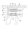
- FIG. 1 is a schematic cross-sectional view showing a main part of a configuration example of the first embodiment of the present apparatus
- FIG. 2 shows an internal structure of a horizontal through hole of an inclined shaft, an initial state (A) of a releasing process, and a cylindrical protrusion.
- A initial state
- B mold release state
- this apparatus has a simple structure constituted by an inclined shaft 10 and a vertical shaft 20 that exert an inclined slide function in a mold release apparatus for a mold having an inclined slide mechanism.
- the inclined shaft 10 is a tilted slide part 12 that is bent so that a part near the upper end is a vertical part 11 and the lower side of the vertical part is inclined outward.
- the tilt angle is not strictly defined.
- a horizontal through-hole 13 is opened in the vertical part, and a horizontal part 14 that forms a right angle is formed on the upper side, and the upper surface of the horizontal part is in contact with a cavity plate that is a molded product located above.
- a rod-shaped pin member fixing portion 15 for fixing the rod-shaped pin member 30 in the horizontal direction is formed at the rear end portion.
- the entire vertical direction of the vertical shaft 20 is parallel to the vertical portion 11 of the inclined shaft, and is formed to have substantially the same length as the inclined shaft.
- a cylindrical pin member 21 is fixed to the vertical shaft in the horizontal direction, and a through hole 22 is formed inside.
- a rod-shaped pin member is inserted inside the cylindrical pin member, and the cylindrical pin member is movably inserted into a space 40 formed between the inner wall surface 113 of the horizontal through hole and the outer peripheral surface 31 of the rod-shaped pin member.
- the rod-like pin member is inserted into the through-hole 22 in a state in which the rod-like pin member is movable inside the cylindrical pin member 21, and the rod-like pin member passes through the inside of the through-hole 22 of the vertical shaft and the inside of the tubular pin member 21 to form a horizontal through-hole. Is inserted through the center of the.
- the inclined shaft, the vertical shaft, and the pin member are preferably made of metal, and more preferably made of hard metal.
- the vertical shaft side of the vertical portion of the inclined shaft is a vertical surface.
- the inner surface of the vertical portion can be an inclined surface, and the same inclined surface as the inclined surface of the inclined slide portion. Also good.
- the molded product side of the vertical portion 11 of the inclined shaft is processed so as to have a corresponding shape according to the shape of the hanging part 51 formed below the molded product, and the size and shape such as the width and length of the hanging part. Can be arbitrarily changed by processing the shape of the part in contact with the hanging part on the molded product side of the vertical part.
- the rod-shaped pin member 30 is inserted into the middle portion of the horizontal through hole 13 formed in the vertical portion without moving to the bottom of the cylindrical projection 52 projecting from the hanging portion, and the inner wall surface of the horizontal through hole
- the outer peripheral frame of the cylindrical projecting portion having a predetermined thickness extends from the bottom of the cylindrical projecting portion to the position 41 in contact with the distal end portion of the cylindrical pin member 21.
- Body 152 is received.
- a cylindrical pin member 21 having substantially the same thickness as the outer peripheral frame is movably inserted in a space from the position 41 where the tip of the outer peripheral frame contacts the end of the horizontal through hole.
- the cylindrical pin member 21 is configured to be inserted into a space 40 formed between the inner wall surface of the horizontal through hole and the outer peripheral surface of the rod-shaped pin member.
- the molten resin injected from the injection molding machine passes through the hanging part 51 from the cavity plate, into a space formed between the inner wall surface of the horizontal through-hole and the outer peripheral surface of the rod-shaped pin member inserted through the center part.
- the outer peripheral frame body 152 of the cylindrical projection portion is formed as a molded product that is filled up to the position 41 in contact with the tip end portion of the cylindrical pin member 21 inserted into the space and protrudes from the hanging portion. That is, the space between the inner wall surface of the horizontal through hole and the outer peripheral surface of the rod-shaped pin member to the tip end surface of the cylindrical pin member forms a molten material filling space that becomes the outer peripheral frame of the cylindrical protrusion. It will be.
- FIG. 3 is a view for explaining the operation and function of the apparatus in the mold release process of the present apparatus according to the first embodiment.
- the initial state (A) of the mold release process, the operating state (B) during the shaft ascending, The operation state (C) at the time of mold release is shown.
- the inclined shaft 10 and the vertical shaft 20 move up and down simultaneously in a synchronized state.
- the inclined shaft has a function of an inclined slide mechanism and executes an inclined slide motion, and the vertical portion 11 moves closer to the vertical shaft side by the operation of the inclined slide mechanism of the inclined slide portion 12.
- the mold release process proceeds, the mold moves upward in the U direction and moves horizontally in the H direction to approach the vertical shaft side.
- the vertical shaft only moves up and down simultaneously with the inclined shaft and does not move in the horizontal direction. Therefore, even if the mold release process proceeds from the start of the mold release process and the shaft rises, the state where the tip of the cylindrical pin member is in contact with the tip of the cylindrical protrusion 52 is maintained as it is. Become.
- the molded product side of the vertical portion is in contact with the hanging portion 51, and the horizontal through hole 13
- a rod-shaped pin member 30 is inserted through the center portion, and a cylindrical pin member 21 is inserted into the space 40 up to a predetermined position.
- the outer peripheral frame of the cylindrical projection portion up to a position 41 that contacts the tip of the cylindrical pin member.
- the molten resin to be 152 is filled.
- the mold release process is started after the molten resin is cooled and solidified.
- the tip of the cylindrical pin member inserted through the space 40 protrudes from the horizontal through-hole 13, and the tip of the cylindrical pin member does not leave even when the mold release process proceeds and the shaft rises to the maximum.
- the cylindrical projection is pressed against the tip of the outer peripheral frame body so as not to move (see FIGS. 2B and 3C). If the cylindrical protrusion is in contact with the vertical part of the inclined shaft, the cylindrical protrusion moves along with the rising and horizontal movement of the inclined shaft.
- the cylindrical protrusion is prevented from moving together with the inclined shaft by pressing the cylindrical pin member so that the cylindrical protrusion does not move by contacting the distal end of the cylindrical protrusion with the distal end of the cylindrical protrusion. be able to.
- the vertical portion is separated from the hanging portion 51 and the cylindrical projection 52, and the rod-shaped pin member 30 is the cylindrical projection. 52 from the hollow portion 154.
- the distal end portion of the cylindrical pin member is pressed against the distal end portion of the outer peripheral frame body of the cylindrical projection portion so that the cylindrical projection portion does not move.
- the contact of the tip of the cylindrical pin member with the tip of the cylindrical protrusion does not give a pressing force from the side of the cylindrical pin member, but is merely touching so that the cylindrical protrusion does not move. It is in a state. Thereafter, the molded product is pushed upward while the tip of the cylindrical pin member presses the cylindrical protrusion, and the mold release process is completed. With such operations and functions, the mold release assisting apparatus assists and assists the mold release process to be performed smoothly.
- the timing for executing such a mold release support operation should be an appropriate processing time that is not excessive or deficient in consideration of various conditions such as the type of plastic used as a raw material and the influence of auxiliary materials used, the structure of the molded body, and the ambient temperature. It should be decided in consideration.
- an elevating guide portion having a guide hole for receiving the inclined shaft and the vertical shaft from the lower side is fixedly disposed in the mold, and the vertical shaft of the inclined shaft is arranged according to the guide of the elevating guide portion. The horizontal movement to the side and the simultaneous raising and lowering movement of the inclined shaft and the vertical shaft are reliably performed.
- a set of structures including a horizontal through hole, a rod-shaped pin member, a cylindrical pin member, and a through-hole formed in a vertical shaft, which are necessary elements for forming and releasing the cylindrical protrusion.
- a molded product in the case where the first embodiment is applied is a molded product in which one cylindrical protrusion shown in FIG. 10A is formed.
- a molded product in which a plurality of cylindrical protrusions are formed by arranging a plurality of the above-mentioned set of constituent parts in the horizontal and vertical directions, and by installing a plurality of the apparatus. Can be formed (see FIGS. 10B and 10C).
- FIG. 4 is a schematic cross-sectional view showing the main part of the configuration example of the second embodiment
- FIG. 5 is an initial state (A) in the mold release process of the second embodiment, and an operating state (B) in the middle of raising the shaft.
- the operation state (C) at the time of mold release is shown.
- the tip end surface 32 of the rod-shaped pin member 52 extends from the bottom of the cylindrical protrusion 52 to the horizontal through hole 13 formed in the vertical portion of the inclined shaft.
- the rod-shaped pin member 30 is configured to be inserted with a certain interval (constant width) 153 between them.
- the cylindrical projection to be molded is a hollow cylindrical body that is open at both ends, and the cylindrical projection in which the rod-shaped pin member protrudes from the hanging portion.
- the tip of the rod-shaped pin member penetrates through the hollow portion of the cylindrical projection portion until it reaches the bottom of the portion.
- the bottom surface is formed on one end side of the cylindrical projecting portion to be molded by configuring the rod-shaped pin member so as to be inserted from the bottom side of the cylindrical projecting portion at a constant interval. It can be set as the bottomed cylindrical body which forms.
- the bottom side of the cylindrical projection is the bottom, and the thickness of the bottom is arbitrarily determined by the distance between the tip surface of the rod-shaped pin member and the bottom of the cylindrical projection.
- the thickness of the bottom is arbitrarily determined by the distance between the tip surface of the rod-shaped pin member and the bottom of the cylindrical projection.
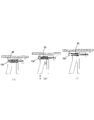
- FIG. 6 is a schematic perspective view showing a configuration example of the third embodiment.
- the inclined shaft 10 and the vertical shaft 20 in which the horizontal portion 14 and the rod-shaped pin member fixing portion 15 are formed are extended in the horizontal direction to form a cylindrical protrusion.
- a set of constituent parts including a horizontal through hole 13, a rod-shaped pin member 30, a cylindrical pin member 21, and a through-hole 22 formed in a vertical shaft.
- a component portion is referred to as a horizontal number corresponding to the number of cylindrical projections to be molded, and the rod-shaped pin member and the mechanism for operating the cylindrical pin member are operated simultaneously. Configured.
- FIG. 6 three sets of components are arranged.
- one set of three constituent parts is arranged, but in the present invention, one set of two or more arbitrary numbers of constituent parts can be arranged.
- the number of components arranged in a set is determined by comprehensively adjusting the scale of the mold, the length (height), width, and inclination angle of the inclined slide portion of the inclined shaft. Note that the description of the operation of each set of components, the operation and function of the apparatus has been described above, and is omitted here.
- FIG. 7 is a schematic cross-sectional view showing the main part of the configuration example of the fourth embodiment.
- the fourth embodiment of the present apparatus has a set of components in the vertical direction as shown in FIG.
- a plurality of components are arranged in the vertical direction by a number corresponding to the number of cylindrical projections to be molded, and a rod-shaped pin member and a cylindrical pin member are provided.
- a mechanism for actuating is configured to actuate simultaneously.
- FIG. 7 shows a configuration in which two sets of components are arranged in the vertical direction.
- a molded product is formed in which two cylindrical protrusions shown in the front row of FIG.
- a set of constituent parts can be arranged in an arbitrary number of three or more in the vertical direction.
- a molded product is formed in which three cylindrical protrusions shown in the rear row of FIG. Note that the number of components arranged in a set is determined by comprehensively adjusting the size of the mold. Note that the description of the operation of each set of components, the operation and function of the apparatus has been described above, and is omitted here.
- the object to be molded is a single cylindrical projection that protrudes from one drooping portion.
- a set of components is arranged in the horizontal direction.
- the number of cylindrical protrusions to be molded can be increased by the desired number in the horizontal direction, and the desired number can be continuously formed in the vertical direction.
- each cylindrical pin member tip portion presses the respective cylindrical projections so as not to move until the molded product is pushed upward and the mold release is performed. Even if it is the mold release process of the molded product which formed the shape projection part, it will assist and support so that it may be implemented smoothly.
- FIG. 8 is a schematic cross-sectional view showing a main part of a configuration example of the fifth embodiment.
- a plurality of release support devices according to the first to fourth embodiments each including the inclined shaft 10 and the vertical shaft 20 are arranged in the same direction.
- a mechanism for operating the rod-shaped pin member and the cylindrical pin member is configured to operate simultaneously.
- two devices are arranged in the same direction, but in the present invention, three or more devices can be arranged.
- the number of the apparatus is determined by comprehensively adjusting the size of the mold.
- the sixth embodiment has a first to a fourth shaft including an inclined shaft and a vertical shaft, as shown in FIG.
- Any one of the mold release assisting devices according to the embodiment is arranged so that the inclined shaft faces each other, and a mechanism for operating the rod-shaped pin member and the cylindrical pin member is configured to operate simultaneously.
- two devices are arranged so that the inclined shaft side of the device faces each other, but two devices can also be arranged so that the rod-shaped pin member fixing portion 15 side of the inclined shaft of the device faces each other.
- the arrangement of the apparatus is determined by comprehensively adjusting the size of the mold.
- FIGS. 10 (B) and 10 (C) it is possible to mold the molded products arranged in two rows in the longitudinal direction. .
- the molded products are arranged in two rows in the longitudinal direction, but three or more rows of the molded products can be arranged in the vertical direction by arranging three or more apparatuses.
- the description of the components, operations, functions, and the like of this apparatus has been described above and is omitted here.
- FIG. 10A shows an example of a molded product formed by applying the first embodiment, and shows an example of a molded product formed with one cylindrical protrusion.
- FIG. 10B is an example of a molded product formed by applying the third, fifth, or sixth embodiment, and three cylindrical protrusions arranged in the horizontal direction are arranged in two rows of the front row and the rear row, respectively.
- FIG. 10C is an example of a molded product formed by applying the third, fourth, fifth, or sixth embodiment, and three cylindrical protrusions formed by connecting two upper and lower rows in the front row.
- the three cylindrical projections formed by connecting the upper, middle, and lower three lines in the rear row are respectively arranged in the horizontal direction.
- the molded product shown here is an example, It is not limited to these, The molded product to which the mold release assistance apparatus which concerns on this invention is applied can be made into various shapes.
- the horizontal through-hole 13, the rod-shaped pin member 30, the cylindrical pin member 21, and the through-hole 22 formed in the vertical shaft have the cross-sectional shape of the outer peripheral frame body or hollow of the cylindrical projection portion to be molded.
- a cylindrical protrusion having a desired shape can be formed.
- the outer peripheral frame 152 and the hollow portion 154 of the cylindrical projection portion to be molded have a circular cylindrical shape, but in the present invention, a horizontal through hole, a rod-shaped pin member, etc. are appropriately processed.
- the cross-sectional shape of the outer peripheral frame body and the hollow portion of the cylindrical protrusion can be made not only circular but also triangular, quadrangular, rhombus, floral pattern and other various shapes.
- cross-sectional shapes are determined by the cross-sectional shape of the space between the inner wall surface of the horizontal through-hole and the outer peripheral surface of the rod-shaped pin member, the horizontal through-hole that becomes a necessary part for changing the shape of the space,
- a cylindrical protrusion having a desired shape can be formed.
- the cross-sectional shapes of the outer peripheral frame body 152 and the hollow portion 154 of the cylindrical projection of the molded product to which the present invention is applied can be various.
- FIG. 11 is a diagram showing an example of the cylindrical protrusion 52 having a circular cross-sectional shape of the hollow portion
- (A) is an example in which the cross-sectional shape of the outer peripheral frame 152 is circular
- (B) is an example of the outer peripheral frame.
- An example in which the cross-sectional shape is a triangle
- (C) is an example in which the cross-sectional shape of the outer peripheral frame is a quadrangle
- (D) is an example in which the cross-sectional shape of the outer peripheral frame is a circular shape that forms a protrusion on the outer periphery.
- 12A and 12B are diagrams showing an example of a cylindrical projection having a circular cross-sectional shape on the outer peripheral surface of the outer peripheral frame 152.
- FIG. 12A is an example in which the cross-sectional shape of the hollow portion 154 is a rhombus
- FIG. (C) shows an example in which the cross-sectional shape of the hollow portion is a quadrangle.
- FIG. 13 is a view showing an example of the cross-sectional shape of both the hollow portion 154 of the cylindrical protrusion and the outer peripheral frame body 152
- (A) is an example in which the cross-sectional shape of the hollow portion and the outer peripheral frame body is a rhombus
- (B) Shows an example in which the cross-sectional shapes of the hollow part and the outer peripheral frame are triangular
- (C) shows an example in which the cross-sectional shape of the hollow part and the outer peripheral frame is rectangular.
- these shapes are illustrations and are not limited to these.
- the outer diameter D1, the inner diameter D2, and the length L of the cylindrical projection 52 to be molded and the thickness T of the outer peripheral frame 152 of the cylindrical projection are each set.
- the outer diameter, inner diameter, and length of the cylindrical projection to be molded, and the thickness of the outer peripheral frame of the cylindrical projection are determined.
- the length (height) size of the cylindrical protrusion is not limited to the length from the bottom of the cylindrical protrusion in the space 40 to the end surface of the cylindrical pin member, but the width of the vertical portion of the inclined shaft, the inclined slide portion Are determined by comprehensively adjusting the inclination angle and the length (height) of the inclined shaft.
- any number, shape, and size can be formed inside the case where the ribs that are open on one side become the outer frame. It is possible to integrally mold a plastic product having a very complicated shape and structure in which the cylindrical projection portion protrudes. Furthermore, by applying a combination of the above-mentioned apparatus and the mold release assisting apparatus proposed by the inventor described above (Japanese Patent Application No. 2014-555013) as appropriate, a non-cylindrical protruding part can be obtained. It is possible to integrally mold plastic products having a more complicated shape and structure.
- plastic molded products are used in a wide range of fields such as household electrical appliances and other daily necessities, office supplies, various industrial machines and devices, automobiles, railways, airplanes, and other transportation / transportation engines. It is used for the manufacture of molded products in Japan and is expected to contribute to a wide range of industrial fields.
Abstract
Description
11 垂直部位
12 傾斜スライド部位
13 水平貫通孔
14 水平部
15 棒状ピン部材固着部
20 垂直シャフト
21 筒状ピン部材
22 貫通孔
30、30-1、30-2、30-3 棒状ピン部材
31 棒状ピン部材外周面
32 棒状ピン部材先端面
40 空間(溶融樹脂充填空間、筒状ピン部材挿通空間)
41 筒状突起部外周枠体と筒状ピン部材先端部が接する位置
50 成形品(キャビティプレート)
51 垂下部
52 筒状突起部
113 水平貫通孔内壁面
152 筒状突起部外周枠体
153 筒状突起部底辺と棒状ピン部材先端面との間隔(幅)
154 筒状突起部中空部
D1 筒状突起部外径
D2 筒状突起部内径
L 筒状突起部長さ
T 筒状突起部外周枠体の厚さ
U 上昇移動方向
H 水平移動方向
DESCRIPTION OF
41 Position at which the outer peripheral frame of the cylindrical protrusion contacts the cylindrical
51 Hanging
154 Tubular projection hollow D1 Tubular projection outer diameter D2 Tubular projection inner diameter L Tubular projection length T Thickness of cylindrical projection outer peripheral frame U Ascending movement direction H Horizontal movement direction
Claims (7)
- 傾斜スライド機構を備えた金型における成形品の離型装置において、
上端部付近における一部が垂直状の垂直部位を形成し、当該垂直部位の下方側が外向き傾斜状に加工され傾斜スライド部位となるように形成し、垂直部位の内部に水平貫通孔を、上辺に直角をなす水平部を、後端部に棒状ピン部材を水平方向に向けて固着する棒状ピン部材固着部をそれぞれ形成した傾斜シャフトと、前記傾斜シャフトの垂直部位と全体が並行をなし該傾斜シャフトとほぼ同じ長さに形成されたシャフトであって、傾斜シャフトの水平貫通孔の内壁面と棒状ピン部材の外周面との間に形成される空間に移動可能に挿通される筒状ピン部材を水平方向に向けて固着し、当該筒状ピン部材内部を前記棒状ピン部材が移動可能な貫通孔を形成した垂直シャフトと、を備え、
前記傾斜シャフトの垂直部位は、成形品側が成形品の下方に形成される垂下部の形状に対応する形状となるように加工され、垂直部位に形成される水平貫通孔の中心部には棒状ピン部材が垂下部に突出する筒状突起部の底辺に至るまで挿通され、当該水平貫通孔の前記空間には筒状突起部の底辺から垂直シャフトの筒状ピン部材の先端部に接する位置に至るまで所定厚さの筒状突起部の外周枠体が受容され、当該外周枠体の先端部が接する位置から水平貫通孔の端部に至る空間には外周枠体と略同一厚さの筒状ピン部材が移動可能に挿通され、
前記傾斜シャフトと垂直シャフトは同時に昇降運動し、傾斜シャフトの上昇運動の際の垂直シャフト側への接近移動に伴って、傾斜シャフトの垂直部位が成形品の垂下部及び筒状突起部から離れ、前記棒状ピン部材は筒状突起部の中空部から抜け出し、前記空間に挿通された筒状ピン部材先端は当該水平貫通孔から突き出て、筒状ピン部材先端部が筒状突起部の外周枠体先端部に接触して筒状突起部が動かないように押え付け、円滑な離型を支援するように構成されたことを特徴とする成形品の離型支援装置。 In a mold release device for a mold having an inclined slide mechanism,
A part near the upper end part forms a vertical vertical part, and the lower side of the vertical part is formed so as to be inclined outward to form an inclined slide part. A horizontal through-hole is formed inside the vertical part. A tilted shaft formed with a horizontal portion perpendicular to the shaft, and a rod-shaped pin member fixing portion for fixing the rod-shaped pin member to the rear end portion in the horizontal direction, and the vertical portion of the tilted shaft is in parallel with the inclined shaft. A cylindrical pin member that is formed in substantially the same length as the shaft and is movably inserted into a space formed between the inner wall surface of the horizontal through hole of the inclined shaft and the outer peripheral surface of the rod-shaped pin member And a vertical shaft that has a through hole through which the rod-shaped pin member can move inside the cylindrical pin member.
The vertical portion of the inclined shaft is processed so that the molded product side has a shape corresponding to the shape of the hanging portion formed below the molded product, and a bar-like pin is formed at the center of the horizontal through hole formed in the vertical portion. The member is inserted to reach the bottom of the cylindrical projection protruding from the drooping portion, and the space of the horizontal through hole reaches the position in contact with the tip of the cylindrical pin member of the vertical shaft from the bottom of the cylindrical projection. The outer peripheral frame of the cylindrical protrusion having a predetermined thickness is received until the space from the position where the front end of the outer peripheral frame contacts to the end of the horizontal through-hole has the same thickness as the outer peripheral frame. The pin member is movably inserted,
The inclined shaft and the vertical shaft move up and down at the same time, and as the inclined shaft moves upward, the vertical portion of the inclined shaft moves away from the hanging part and the cylindrical protrusion, The rod-shaped pin member comes out of the hollow portion of the cylindrical projection, the tip of the cylindrical pin member inserted into the space protrudes from the horizontal through hole, and the tip of the cylindrical pin member is the outer peripheral frame of the cylindrical projection. A molded product release assisting device configured to support the smooth release by pressing the cylindrical projection so as not to move by contacting the tip. - 前記棒状ピン部材が、筒状突起部の底辺から棒状ピン部材の先端面の間に一定間隔を確保して水平貫通孔に対し挿通される、ことを特徴とする請求項1に記載の成形品の離型支援装置。 2. The molded product according to claim 1, wherein the rod-shaped pin member is inserted into the horizontal through hole with a certain interval between the bottom of the cylindrical protrusion and the tip surface of the rod-shaped pin member. Mold release support device.
- 前記傾斜シャフト及び垂直シャフトが水平方向に延伸され、水平貫通孔、棒状ピン部材、筒状ピン部材、貫通孔からなる一組の構成部分が成形対象とする筒状突起部の数に応じて対応する数だけ水平方向に配設され、棒状ピン部材及び筒状ピン部材を作動させるための機構が同時に作動するように構成される、ことを特徴とする請求項1又は2のいずれかに記載の成形品の離型支援装置。 The inclined shaft and the vertical shaft are extended in the horizontal direction, and a set of components including a horizontal through hole, a rod-shaped pin member, a cylindrical pin member, and a through-hole corresponds to the number of cylindrical protrusions to be molded. 3. The device according to claim 1, wherein a number of the horizontal pins are arranged in a horizontal direction, and a mechanism for operating the rod-shaped pin member and the cylindrical pin member is configured to operate simultaneously. Mold release support device for molded products.
- 前記一組の構成部分が成形対象とする筒状突起部の数に応じて対応する数だけ垂直方向に配設され、棒状ピン部材及び筒状ピン部材を作動させるための機構が同時に作動するように構成される、ことを特徴とする請求項1~3のいずれかに記載の成形品の離型支援装置。 The set of components is arranged in a vertical direction corresponding to the number of cylindrical protrusions to be molded, and the rod-shaped pin member and the mechanism for operating the cylindrical pin member are operated simultaneously. The mold release assisting device according to any one of claims 1 to 3, wherein the device is configured as follows.
- 請求項1~4のいずれかに記載の離型支援装置が同一方向に向けて複数配設され、前記棒状ピン部材及び筒状ピン部材を作動させるための機構が同時に作動する、ことを特徴とする成形品の離型支援装置。 A plurality of mold release support apparatuses according to any one of claims 1 to 4 are arranged in the same direction, and a mechanism for operating the rod-shaped pin member and the cylindrical pin member operates simultaneously. Mold release support device for molded products.
- 請求項1~4のいずれかに記載の離型支援装置が傾斜シャフト側を対向させて配設され、前記棒状ピン部材及び筒状ピン部材を作動させるための機構が同時に作動する、ことを特徴とする成形品の離型支援装置。 5. The mold release assisting device according to claim 1, wherein the releasing shaft support device is arranged with the inclined shaft side facing each other, and the mechanism for operating the rod-shaped pin member and the cylindrical pin member operates simultaneously. Mold release support device for molded products.
- 前記水平貫通孔、棒状ピン部材、筒状ピン部材および垂直シャフト内部に形成される貫通孔の断面形状が、成形対象とする筒状突起部の外周枠体および/または筒状突起部の中空部の断面形状に対応する形状に応じて決定され加工される、ことを特徴とする請求項1~6のいずれかに記載の成形品の離型支援装置。
The cross-sectional shape of the horizontal through hole, the rod-shaped pin member, the cylindrical pin member, and the through-hole formed inside the vertical shaft has an outer peripheral frame body of the cylindrical projection portion to be molded and / or a hollow portion of the cylindrical projection portion. The mold release assisting device according to any one of claims 1 to 6, characterized in that it is determined and processed according to a shape corresponding to the cross-sectional shape of the molded product.
Priority Applications (3)
| Application Number | Priority Date | Filing Date | Title |
|---|---|---|---|
| EP15889169.7A EP3235617B1 (en) | 2015-04-15 | 2015-04-15 | Device for assisting in release of molded product |
| JP2015534844A JP5872120B1 (en) | 2015-04-15 | 2015-04-15 | Mold release support device |
| PCT/JP2015/061568 WO2016166831A1 (en) | 2015-04-15 | 2015-04-15 | Device for assisting in release of molded product |
Applications Claiming Priority (1)
| Application Number | Priority Date | Filing Date | Title |
|---|---|---|---|
| PCT/JP2015/061568 WO2016166831A1 (en) | 2015-04-15 | 2015-04-15 | Device for assisting in release of molded product |
Publications (1)
| Publication Number | Publication Date |
|---|---|
| WO2016166831A1 true WO2016166831A1 (en) | 2016-10-20 |
Family
ID=55362176
Family Applications (1)
| Application Number | Title | Priority Date | Filing Date |
|---|---|---|---|
| PCT/JP2015/061568 WO2016166831A1 (en) | 2015-04-15 | 2015-04-15 | Device for assisting in release of molded product |
Country Status (3)
| Country | Link |
|---|---|
| EP (1) | EP3235617B1 (en) |
| JP (1) | JP5872120B1 (en) |
| WO (1) | WO2016166831A1 (en) |
Citations (4)
| Publication number | Priority date | Publication date | Assignee | Title |
|---|---|---|---|---|
| JPH0347110U (en) * | 1989-09-16 | 1991-05-01 | ||
| JPH0735015U (en) * | 1993-12-14 | 1995-06-27 | 河西工業株式会社 | Injection-molded products and injection-molding dies |
| US20060045933A1 (en) * | 2004-08-24 | 2006-03-02 | Chihyu Chen | Mold assembly for forming a plastic article having a complicated shape |
| JP2007118429A (en) * | 2005-10-28 | 2007-05-17 | Toyota Motor Corp | Structure of mold for injection molding |
Family Cites Families (1)
| Publication number | Priority date | Publication date | Assignee | Title |
|---|---|---|---|---|
| WO2015193936A1 (en) * | 2014-06-16 | 2015-12-23 | ケンモールドサービス株式会社 | Release assistance device for molded article |
-
2015
- 2015-04-15 WO PCT/JP2015/061568 patent/WO2016166831A1/en active Application Filing
- 2015-04-15 EP EP15889169.7A patent/EP3235617B1/en active Active
- 2015-04-15 JP JP2015534844A patent/JP5872120B1/en active Active
Patent Citations (4)
| Publication number | Priority date | Publication date | Assignee | Title |
|---|---|---|---|---|
| JPH0347110U (en) * | 1989-09-16 | 1991-05-01 | ||
| JPH0735015U (en) * | 1993-12-14 | 1995-06-27 | 河西工業株式会社 | Injection-molded products and injection-molding dies |
| US20060045933A1 (en) * | 2004-08-24 | 2006-03-02 | Chihyu Chen | Mold assembly for forming a plastic article having a complicated shape |
| JP2007118429A (en) * | 2005-10-28 | 2007-05-17 | Toyota Motor Corp | Structure of mold for injection molding |
Non-Patent Citations (1)
| Title |
|---|
| See also references of EP3235617A4 * |
Also Published As
| Publication number | Publication date |
|---|---|
| EP3235617B1 (en) | 2020-01-01 |
| EP3235617A1 (en) | 2017-10-25 |
| JPWO2016166831A1 (en) | 2017-04-27 |
| EP3235617A4 (en) | 2018-05-16 |
| JP5872120B1 (en) | 2016-03-01 |
Similar Documents
| Publication | Publication Date | Title |
|---|---|---|
| US6659760B2 (en) | Mechanism for moving a screw rod relative to molds for manufacturing products having holds | |
| JP5872120B1 (en) | Mold release support device | |
| JP5698988B2 (en) | Injection mold, injection molding method using the same, injection molded product, and injection molding machine | |
| JP5858437B2 (en) | Undercut processing mechanism | |
| CN103158231A (en) | Injection mold | |
| JP5414009B2 (en) | Mold for resin molding, resin molding method and resin molded product | |
| CN103909630A (en) | Ejector sleeve ejection mechanism | |
| KR101696068B1 (en) | Slide core assembly for processing under cut with two angles at a time | |
| JP5307634B2 (en) | Injection mold | |
| CN104245271A (en) | Mold for vehicle bumper fascia and associated molding technique | |
| JP6613579B2 (en) | Injection mold and method of manufacturing injection molded product | |
| JP5762649B1 (en) | Mold release support device | |
| JP6679470B2 (en) | Mold device, insert molded article manufacturing method, and insert molded article | |
| KR100652262B1 (en) | Length regulator of mold | |
| KR101813677B1 (en) | Injection molding apparatus | |
| KR101655987B1 (en) | Injection mold having many of undercut molding core with shrinkable and expandable | |
| CN203496180U (en) | Sliding block thimble delay ejector mechanism | |
| CN203092972U (en) | Ejector sleeve ejection mechanism | |
| CN105438089A (en) | Plastic part with reduced reading defaults | |
| JP6054565B1 (en) | Mold | |
| JP2011178090A (en) | Mold assembly | |
| CN103264478A (en) | Four-open type mold | |
| JP2012143906A (en) | Injection mold | |
| JP5826648B2 (en) | Mold for partial compression molding | |
| JP2016144916A (en) | Injection molding die and production method of resin molding article using the same |
Legal Events
| Date | Code | Title | Description |
|---|---|---|---|
| ENP | Entry into the national phase |
Ref document number: 2015534844 Country of ref document: JP Kind code of ref document: A |
|
| 121 | Ep: the epo has been informed by wipo that ep was designated in this application |
Ref document number: 15889169 Country of ref document: EP Kind code of ref document: A1 |
|
| REEP | Request for entry into the european phase |
Ref document number: 2015889169 Country of ref document: EP |
|
| WWE | Wipo information: entry into national phase |
Ref document number: 2015889169 Country of ref document: EP |
|
| NENP | Non-entry into the national phase |
Ref country code: DE |