WO2016163470A1 - 医療機器 - Google Patents
医療機器 Download PDFInfo
- Publication number
- WO2016163470A1 WO2016163470A1 PCT/JP2016/061428 JP2016061428W WO2016163470A1 WO 2016163470 A1 WO2016163470 A1 WO 2016163470A1 JP 2016061428 W JP2016061428 W JP 2016061428W WO 2016163470 A1 WO2016163470 A1 WO 2016163470A1
- Authority
- WO
- WIPO (PCT)
- Prior art keywords
- battery
- medical device
- expansion
- housing
- sensor
- Prior art date
- Legal status (The legal status is an assumption and is not a legal conclusion. Google has not performed a legal analysis and makes no representation as to the accuracy of the status listed.)
- Ceased
Links
Images









Classifications
-
- A—HUMAN NECESSITIES
- A61—MEDICAL OR VETERINARY SCIENCE; HYGIENE
- A61N—ELECTROTHERAPY; MAGNETOTHERAPY; RADIATION THERAPY; ULTRASOUND THERAPY
- A61N7/00—Ultrasound therapy
-
- H—ELECTRICITY
- H01—ELECTRIC ELEMENTS
- H01M—PROCESSES OR MEANS, e.g. BATTERIES, FOR THE DIRECT CONVERSION OF CHEMICAL ENERGY INTO ELECTRICAL ENERGY
- H01M10/00—Secondary cells; Manufacture thereof
- H01M10/60—Heating or cooling; Temperature control
- H01M10/65—Means for temperature control structurally associated with the cells
- H01M10/658—Means for temperature control structurally associated with the cells by thermal insulation or shielding
-
- H—ELECTRICITY
- H01—ELECTRIC ELEMENTS
- H01M—PROCESSES OR MEANS, e.g. BATTERIES, FOR THE DIRECT CONVERSION OF CHEMICAL ENERGY INTO ELECTRICAL ENERGY
- H01M10/00—Secondary cells; Manufacture thereof
- H01M10/42—Methods or arrangements for servicing or maintenance of secondary cells or secondary half-cells
- H01M10/48—Accumulators combined with arrangements for measuring, testing or indicating the condition of cells, e.g. the level or density of the electrolyte
-
- H—ELECTRICITY
- H01—ELECTRIC ELEMENTS
- H01M—PROCESSES OR MEANS, e.g. BATTERIES, FOR THE DIRECT CONVERSION OF CHEMICAL ENERGY INTO ELECTRICAL ENERGY
- H01M50/00—Constructional details or processes of manufacture of the non-active parts of electrochemical cells other than fuel cells, e.g. hybrid cells
- H01M50/20—Mountings; Secondary casings or frames; Racks, modules or packs; Suspension devices; Shock absorbers; Transport or carrying devices; Holders
- H01M50/204—Racks, modules or packs for multiple batteries or multiple cells
- H01M50/207—Racks, modules or packs for multiple batteries or multiple cells characterised by their shape
- H01M50/209—Racks, modules or packs for multiple batteries or multiple cells characterised by their shape adapted for prismatic or rectangular cells
-
- H—ELECTRICITY
- H01—ELECTRIC ELEMENTS
- H01M—PROCESSES OR MEANS, e.g. BATTERIES, FOR THE DIRECT CONVERSION OF CHEMICAL ENERGY INTO ELECTRICAL ENERGY
- H01M50/00—Constructional details or processes of manufacture of the non-active parts of electrochemical cells other than fuel cells, e.g. hybrid cells
- H01M50/20—Mountings; Secondary casings or frames; Racks, modules or packs; Suspension devices; Shock absorbers; Transport or carrying devices; Holders
- H01M50/233—Mountings; Secondary casings or frames; Racks, modules or packs; Suspension devices; Shock absorbers; Transport or carrying devices; Holders characterised by physical properties of casings or racks, e.g. dimensions
- H01M50/242—Mountings; Secondary casings or frames; Racks, modules or packs; Suspension devices; Shock absorbers; Transport or carrying devices; Holders characterised by physical properties of casings or racks, e.g. dimensions adapted for protecting batteries against vibrations, collision impact or swelling
-
- H—ELECTRICITY
- H01—ELECTRIC ELEMENTS
- H01M—PROCESSES OR MEANS, e.g. BATTERIES, FOR THE DIRECT CONVERSION OF CHEMICAL ENERGY INTO ELECTRICAL ENERGY
- H01M50/00—Constructional details or processes of manufacture of the non-active parts of electrochemical cells other than fuel cells, e.g. hybrid cells
- H01M50/20—Mountings; Secondary casings or frames; Racks, modules or packs; Suspension devices; Shock absorbers; Transport or carrying devices; Holders
- H01M50/247—Mountings; Secondary casings or frames; Racks, modules or packs; Suspension devices; Shock absorbers; Transport or carrying devices; Holders specially adapted for portable devices, e.g. mobile phones, computers, hand tools or pacemakers
-
- Y—GENERAL TAGGING OF NEW TECHNOLOGICAL DEVELOPMENTS; GENERAL TAGGING OF CROSS-SECTIONAL TECHNOLOGIES SPANNING OVER SEVERAL SECTIONS OF THE IPC; TECHNICAL SUBJECTS COVERED BY FORMER USPC CROSS-REFERENCE ART COLLECTIONS [XRACs] AND DIGESTS
- Y02—TECHNOLOGIES OR APPLICATIONS FOR MITIGATION OR ADAPTATION AGAINST CLIMATE CHANGE
- Y02E—REDUCTION OF GREENHOUSE GAS [GHG] EMISSIONS, RELATED TO ENERGY GENERATION, TRANSMISSION OR DISTRIBUTION
- Y02E60/00—Enabling technologies; Technologies with a potential or indirect contribution to GHG emissions mitigation
- Y02E60/10—Energy storage using batteries
Definitions
- the present invention relates to a medical device equipped with a rechargeable battery.
- US 2012/0078278 A1 discloses a medical device (ultrasonic treatment instrument) having a battery assembly including a plurality of batteries.
- the battery assembly is detachable from the ultrasonic treatment instrument.
- a battery such as a lithium ion secondary battery generates gas due to aging or the like and expands.
- the peripheral member for example, a casing housing the battery
- the peripheral member is deformed or damaged by the pressure due to the expansion, and there is a possibility that the medical device cannot be used normally.
- casings in medical devices must be watertight, their deformation and breakage can be a problem.
- the peripheral member applies a force for suppressing the expansion of the battery, the battery itself may be damaged.
- the battery in an expanded state is continuously used, there is a risk of causing a malfunction or malfunction of the medical device.
- An object of the present invention is to provide a medical device that can detect an expansion state of a battery.
- a medical device includes a first battery that generates electrical energy using an electrolyte solution or an electrolyte polymer, a detection circuit that detects expansion of the first battery, and a detection result of the detection circuit. And a notification unit for notifying that the first battery has expanded.
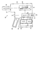
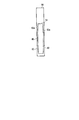
- FIG. 1 is a diagram schematically illustrating one aspect of a medical device according to a first embodiment of the present invention.
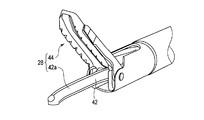
- FIG. 2 is a schematic perspective view showing an example of an end effector of the medical device body.
- FIG. 3 is a diagram schematically illustrating another aspect of the medical device according to the first embodiment.
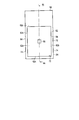
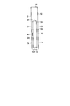
- FIG. 4A is a diagram schematically showing only a battery, an outer case, and a sensor in order to explain the concept of battery expansion detection.
- 4B is a diagram schematically showing a cross section taken along line 4A-4A of FIG. 4A in one mode when the battery is in a new state.
- 4C is a diagram schematically showing a cross section taken along line 4A-4A of FIG. 4A in one mode when the battery is in an aged state.
- FIG. 4A is a diagram schematically showing only a battery, an outer case, and a sensor in order to explain the concept of battery expansion detection.
- 4B is a diagram schematically showing a cross section taken along line 4A-4A
- FIG. 5A is a diagram schematically showing a vertical cross section taken along line 4A-4A of FIG. 4A in another mode when the battery is in a new state.
- FIG. 5B is a diagram schematically showing a vertical cross section taken along line 4A-4A of FIG. 4A in another mode when the battery is in an aged state.
- FIG. 6 is a front view schematically showing an example of a battery assembly having a plurality of batteries in the first embodiment.
- FIG. 7A is a schematic longitudinal sectional view taken along line 6A-6A in FIG. 6 when the battery assembly is in a new state.
- FIG. 7B is a schematic longitudinal sectional view taken along line 6A-6A in FIG. 6 when the battery assembly is in an aged state.
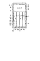
- FIG. 8A is a schematic longitudinal sectional view when the battery assembly is in a new state in the second embodiment.
- FIG. 8B is a schematic vertical cross-sectional view when the battery assembly is in a deteriorated state over time in the second embodiment.
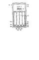
- FIG. 9A is a schematic longitudinal sectional view when the battery assembly is in a new state in the third embodiment.
- FIG. 9B is a schematic vertical cross-sectional view when the battery assembly is in a deteriorated state over time in the third embodiment.
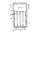
- FIG. 10A is a schematic vertical cross-sectional view when the battery assembly is in a new state in a modification of the third embodiment.
- FIG. 10B is a schematic vertical cross-sectional view of the modified example of the third embodiment when the battery assembly is in a deteriorated state over time.
- FIG. 1 is a diagram schematically showing a medical device 10 according to a first embodiment of the present invention.
- the medical device 10 includes a medical device body 12 and a medical device battery assembly 14.
- a cordless ultrasonic treatment instrument will be described as an example of the medical device body 12.
- the battery assembly 14 can also be used for a medical device body 12 that is different from an ultrasonic treatment instrument such as a cordless high-frequency treatment instrument or a cordless endoscope.
- the medical device body 12 is not limited to a cordless device, and the battery assembly 14 may be used as a backup power source.
- the medical device body 12 is supplied with electric power from the battery assembly 14 by appropriate electrical connection (for example, contact power supply between the contacts 16a and 18a, for example, contact power supply between the contacts 16b and 18b).
- the medical device body 12 may be supplied with electric power from the battery assembly 14 by non-contact power feeding.
- a contactless power feeding method a known electromagnetic resonance method or electromagnetic induction method can be appropriately selected and used.
- the medical device main body 12 and the battery assembly 14 each have a coil (not shown) that transmits and receives power.
- the medical device body 12 includes a housing 22, a switch 24, an energy conversion unit 26, and an end effector 28 that treats living tissue using energy converted by the energy conversion unit 26.
- the energy conversion unit 26 is an ultrasonic transducer.
- the housing 22 includes a housing body 32, a grip 34 integrated with the housing body 32, and a movable handle 36.
- the grip 34 is formed with a slot 38 into which the battery assembly 14 is attached and detached.
- the housing 22 accommodates the battery assembly 14.
- the slot 38 may be formed in the housing body 32 instead of the grip 34.
- the slot 38 may be formed across the housing body 32 and the grip 34.
- the battery assembly 14 is attached from the proximal end of the grip 34 to the slot 38 of the grip 34 held by the operator of the medical device main body 12, for example. For this reason, the battery assembly 14 is formed as a part of the grip 34 held by the operator.
- the battery assembly 14 may be disposed at a position in the medical device body 12 that is not gripped by the operator of the medical device body 12. That is, the battery assembly 14 may be incorporated in the medical device body 12. For example, when a lid (not shown) is formed in the slot 38, the battery assembly 14 is used by being incorporated inside the medical device main body 12 and is not directly gripped by the operator.
- the ultrasonic transducer 26 is provided inside the housing body 32.
- the ultrasonic transducer 26 may be detachable from the housing body 32.
- the switch 24 is disposed in the housing 22 at a position where the operator can operate it while holding the grip 34.
- the switch 24 is electrically connected to a controller 52 described later in a state where the battery assembly 14 is attached to the medical device main body 12. When the switch 24 is pressed, the controller 52 supplies appropriate power to the ultrasonic transducer 26 from a battery (first battery) 54 described later.
- FIG. 2 is a schematic perspective view showing an example of the end effector 28 of the medical device main body 12.
- the end effector 28 includes, for example, a probe 42 connected to the ultrasonic transducer 26 and a jaw 44 that opens and closes between the treatment portion 42a at the distal end of the probe 42 in accordance with the operation of the movable handle 36. Since the ultrasonic transducer 26 converts electric power into ultrasonic vibration, the ultrasonic vibration generated by the ultrasonic transducer 26 is transmitted from the proximal end of the probe 42 toward the treatment portion 42a at the distal end.
- the energy conversion unit 26 is not limited to an ultrasonic transducer, and may be a heater that converts electric power into thermal energy, or a high-frequency energy output body (electrode) that converts electric power into high-frequency energy.
- the structure of the end effector 28 can be changed as appropriate.
- the battery assembly 14 includes a controller 52, a battery 54 that generates electrical energy using an electrolyte solution or an electrolyte polymer, and an outer case (housing) 56 that houses the battery 54.
- the battery assembly 14 includes a detection circuit 92 that detects expansion of the battery 54 and a notification unit 94 that notifies expansion of the battery 54 based on the detection result of the detection circuit 92.
- One or more sensors 96 are provided in the outer case 56. The sensor 96 constitutes a part of the detection circuit 92.
- the controller 52 includes a part of the detection circuit 92. For this reason, the controller 52 may integrate the detection circuit 92 as a part of the controller 52.
- the controller 52 is disposed in a state in which the battery 54 is disposed in the outer case 56.
- the battery assembly 14 has the controller 52 here, but the medical device main body 12 may have the controller 52 as shown in FIG. That is, the medical device main body 12 and the controller 52 of the battery assembly 14 may be configured to be electrically detachably connected to each other through the contacts 16a, 18a, 16b, 18b (see FIG. 1).
- the main body 12 and the controller 52 that controls the battery assembly 14 may be electrically connected at all times (see FIG. 3).
- the controller 52 includes a processor including a CPU or an ASIC.
- the contacts 18a and 18b of the controller 52 of the battery assembly 14 are electrically connected to the contacts 16a and 16b of the medical device main body 12, respectively.
- the switch 24 and the controller 52 are electrically connected by contact between the contacts 16a and 18a.
- the ultrasonic transducer 26 and the controller 52 are electrically connected by contact between the contacts 16b and 18b. Therefore, for example, when the surgeon operates the switch 24 and inputs a signal to the controller 52, the controller 52 supplies power to the ultrasonic transducer 26 from the battery 54 through the controller 52.
- the ultrasonic transducer 26 converts electric power into ultrasonic vibration, and the ultrasonic vibration is transmitted from the ultrasonic transducer 26 to the probe 42.
- the controller 52 optimizes, for example, charging of the battery 54 of the battery assembly 14 when charging, and appropriately controls the electrical energy (electric power) supplied to the ultrasonic transducer 26 when supplying electrical energy.
- the controller 52 stores the number of times the battery assembly 14 is used with respect to the medical device main body 12 and the state of use in a memory (not shown) of the controller 52, and is used to check the voltage value (starting force) of the battery 54. Can be done. That is, the controller 52 can measure the degree of deterioration of the battery 54 of the battery assembly 14.
- FIG. 4A is a diagram schematically showing only the battery 54, the outer case 56, and the sensor 96 in order to explain the concept of battery 54 expansion detection.
- 4B is a diagram schematically showing a cross section taken along line 4A-4A in FIG. 4A when the battery 54 is in a new state.
- FIG. 4C is a diagram schematically showing a cross section taken along line 4A-4A in FIG. 4A when the battery 54 is in a deteriorated state over time.
- FIG. 4C schematically shows a state in which the body 62 of the battery 54 is inflated to reduce the internal pressure of the battery 54 due to the influence of the gas generated in the battery 54.
- the body 62 of the battery 54 is formed in a rectangular parallelepiped shape, for example.
- Each body 62 has a pair of first body surface 62a, second body surface 62b, and third body surface 62c.
- the surface area of the body 62 decreases in the order of the first body surface 62a, the second body surface 62b, and the third body surface 62c.
- the first body surface 62a is formed to be several times larger than the second body surface 62b, for example, and several times larger than the third body surface 62c.
- the second body surface 62b and the third body surface 62c may have the same surface area or may be different.
- first body surface 62a to the third body surface 62c are formed of the same material and with the same thickness, when the battery 54 expands due to an increase in internal pressure due to gas generated according to the aging of the battery 54, the surface area is increased. The probability that the large first body surface 62a will swell is much higher than the probability that the other surface swells (FIG. 4C).
- a material that is brittlely broken by internal pressure is not used for the body 62, but a material that exhibits appropriate ductility and is appropriately deformed and expanded.
- the expansion amount of the first body surface 62a becomes larger than the expansion amount of the second body surface 62b, and the expansion amount of the first body surface 62a becomes larger than the expansion amount of the third body surface 62c. .
- the outer case 56 is made of, for example, a metal material such as a stainless steel material or a plastic material. A material similar to that for forming the housing 22 of the medical device body 12, that is, the exterior can be used for the exterior case 56.
- the exterior case 56 includes a bottom surface portion 72 and a wall portion 74 that extends in one direction from the outer edge of the bottom surface portion 72 toward the normal direction of the bottom surface portion 72.
- the bottom surface portion 72 and the wall portion 74 form a storage portion 76 in which one or more batteries 54 are stored.
- the wall portion 74 has four planes (a pair of first case surface 82 and second case surface 84, respectively).
- the first case surface 82 of the outer case 56 faces the first body surface 62 a of the battery 54.
- the second case surface 84 of the exterior case 56 faces the second body surface 62 b of the battery 54.
- the sensor 96 is a detection unit that can detect the expansion of the battery 54 as a change in physical quantity.
- the sensor 96 is, for example, a pressure sensor that measures pressure applied to the battery 54 or the outer case 56, a strain sensor that measures strain of the battery 54 or the outer case 56, or a distance between the battery 54 and the outer case 56. A distance sensor or the like can be used.
- the pressure sensor 96 is a pressure sensor.
- the pressure sensor 96 is attached to the battery 54.
- the pressure sensor 96 is attached near the center of one of the pair of first body surfaces 62a of the battery 54, for example, as schematically shown in FIGS. 4A to 4C.
- the pressure sensor 96 measures the force (pressure) applied from the inside of the body 62 to the attached first body surface 62a, converts it into an electrical signal, and outputs it.
- the first body surface 62a is more than the other surfaces (the second body surface 62b and the third body surface 62c) when the battery 54 is expanded due to an increase in internal pressure due to the generation of gas due to aging of the battery 54.
- the pressure sensor 96 can detect an increase in pressure due to expansion of the battery 54 with high sensitivity.
- the pressure sensor 96 may be attached to the outer case 56 as schematically shown in FIGS. 5A and 5B.
- the pressure sensor 96 detects the expansion of the battery 54 by detecting the pressure applied to the battery 54 or the outer case 56 of the housing 22. Even when the pressure sensor 96 is attached to the exterior case 56, the pressure sensor 96 is disposed near the center of the first case surface 82 of the exterior case 56 facing the first body surface 62a of the battery 54 for the above-described reason. Is preferred.
- the pressure sensor 96 can immediately detect the expansion of the battery 54.
- the pressure sensor 96 cannot immediately detect the expansion of the battery 54. Absent. That is, it should be noted that the expansion of the battery 54 is not detected unless the battery 54 expands to some extent and exerts a pressure on the pressure sensor 96 that can be detected by the pressure sensor 96.
- the strain sensor 96 is a strain sensor.
- the strain sensor 96 is attached to the battery 54.
- the strain sensor 96 is attached near the center of one of the pair of first body surfaces 62a of the battery 54, for example, as schematically shown in FIGS. 4A to 4C.
- the strain sensor 96 measures a strain (a minute change in mechanical dimensions) generated in the attached first body surface 62a as a change in electrical resistance.
- the first body surface 62a is easier to expand than the other surfaces, and in particular, the vicinity of the center is most likely to expand. That is, the amount of distortion near the center of the first body surface 62a is the largest when the battery 54 is expanded. For this reason, by disposing the strain sensor 96 in the vicinity of the center of the first body surface 62a having the largest strain amount, the strain sensor 96 can detect the strain due to the expansion of the battery 54 with high sensitivity.
- the strain sensor 96 may be attached to the outer case 56. That is, the strain sensor 96 detects the expansion of the first battery 54 a by detecting the amount of strain generated in the first battery 54 or the housing 22. When the strain sensor 96 is attached to the exterior case 56, the strain is not detected until the exterior case 56 is deformed by the expansion of the battery 54, and it is considered that the sensitivity of the strain sensor 96 detecting the expansion of the battery 54 is low. For this reason, when the strain sensor 96 is used as the sensor, it is preferable that the strain sensor 96 is attached to the battery 54 rather than the outer case 56 from the viewpoint of sensitivity.
- the distance sensor 96 is a distance sensor.
- the distance sensor 96 is attached to the battery 54 (FIGS. 4A to 4C) or the outer case 56 (FIGS. 5A and 5B).
- the distance sensor 96 detects the distance between the battery 54 and the outer case 56 using, for example, reflection of laser light or the like. That is, the distance sensor 96 detects the expansion of the battery 54 by detecting the distance between the battery 54 and the housing 22.
- the first body surface 62a is easier to expand than the other surfaces, and in particular, the vicinity of the center is most likely to expand.
- the distance between the vicinity of the center of the first body surface 62a of the battery 54 and the vicinity of the center of the first case surface 82 of the outer case 56 facing the first body surface 62a is most likely to change due to an increase in the pressure of the battery 54. .
- the distance sensor 96 is also disposed near the center of the first body surface 62 a of the battery 54 or near the center of the first case surface 82 of the exterior case 56. Thereby, the distance sensor 96 can detect the change of the distance between them with expansion with high sensitivity.
- a sensor 96 may be attached. That is, since the pair of first body surfaces 62a does not always expand symmetrically, the battery 54 may be provided with a plurality of sensors 96.
- FIGS. 5A and 5B the example in which the sensor 96 is attached to only one of the pair of first case surfaces 82 of the exterior case 56 has been described. However, each of the pair of first case surfaces 82 ( Sensor 96 may be attached to both).
- a plurality of sensors 96 may be provided in the outer case 56.
- the sensor 96 may be provided on both the battery 54 and the outer case 56.
- the sensor 96 may be attached to the outer surface of the outer case 56 or disposed outside as long as the expansion of the battery 54 can be detected as a change in physical quantity that is a detection target of the sensor 96.
- a signal detected by the detection circuit 92 by the sensor 96 is input to the controller 52.
- a notification unit 94 is connected to the controller 52.
- the notification unit 94 detects an expansion (deformation) of the battery 54 or the outer case 56 that is not allowable or greater than a predetermined value. At that time, the user is notified of this based on the control signal from the controller 52.
- the notification unit 94 may be provided in the battery assembly 14 (see FIG. 1), may be provided in the medical device body 12 (see FIG. 3), or separately from the medical device body 12 and the battery assembly 14. It may be provided.
- the notification unit 94 includes, for example, a display unit, and performs visual notification by displaying a warning screen using characters or the like, or emitting light from an LED.
- the notification unit 94 includes, for example, a sound generation unit, and makes an auditory notification such as a warning sound or a voice message.
- the notification unit 94 makes a notification by combining these.
- the controller 52 can disable the use of the battery assembly 14 once the detection circuit 92 detects that the battery 54 has expanded a predetermined amount or more. That is, the controller 52 stops outputting electric energy from the battery assembly 14 to the outside. After detecting that the battery 54 has expanded by a predetermined amount or more, the controller 52 terminates the current treatment and then removes the battery assembly 14 from the slot 38 so that the battery assembly 14 cannot be reused. It may be.
- the notification unit 94 does not necessarily notify when the battery 54 or the outer case 56 is detected to have a predetermined or higher expansion (deformation) that is not acceptable.
- the sensor 96 detects the state of the battery assembly 14 from the time when changes in pressure, strain, distance, and the like can be measured, and when an unacceptable expansion (deformation) of the battery 54 or the outer case 56 is detected. Until you can continue to be determined. For this reason, the notification unit 94 can notify the deterioration degree of the battery 54. For this reason, when the sensor 96 detects an unacceptable expansion (deformation) of the battery 54 or the outer case 56 that is unacceptable, it is preferable that the notification unit 94 makes a notice so as to be particularly noticeable.
- FIG. 6 is a front view schematically showing an example of the battery assembly 14 having a plurality of batteries 54 (here, four batteries 54a, 54b, 54c, 54d) in the first embodiment.
- 7A is a schematic longitudinal sectional view taken along the line 6A-6A in FIG. 6 when the battery assembly 14 is in a new state
- FIG. 7B is a diagram when the battery assembly 14 is in a deteriorated state over time.
- FIG. 6 is a schematic longitudinal sectional view taken along line 6A-6A.
- Each battery 54 a-54 d of the battery assembly 14 includes a body 62 that stores, for example, an electrolyte solution or an electrolyte polymer, and a contact 64 that is electrically connected to the controller 52.
- Examples of the battery 54 having an electrolyte solution or an electrolyte polymer are a lithium ion battery, a sodium ion battery, an alkaline ion battery, and the like.
- the internal structure of the battery 54 is a known appropriate one.
- One or more batteries 54 are disposed in the storage portion 76 of the exterior case 56.
- four batteries 54a-54d are arranged in the storage unit 76 with their orientations aligned. Since the body 62 of each battery 54 a-54 d is formed in a rectangular parallelepiped shape, a plurality of batteries can be easily arranged in the storage portion 76.
- the sensor 96 is, for example, near the center of the first body surface 62a facing the first case surface 82 of the exterior case 56 of the pair of first body surfaces 62a of the first battery 54a. Is attached. Of course, the sensor 96 may be attached to any of the other batteries 54b-54d, a plurality of sensors 96 may be attached to each of the two or more batteries 54a-54d, or a plurality of sensors 96 may be connected to one It may be attached to batteries 54a-54d.
- a gap C1 is formed between the batteries 54a and 54b, between the batteries 54b and 54c, and between the batteries 54c and 54d. That is, a gap C1 is formed between the first body surfaces 62a.
- the battery (first battery) 54 a is installed with a gap C ⁇ b> 1 with respect to the housing 22. In the new state, the gap C ⁇ b> 1 is formed smaller than the allowable expansion amount of the first body surface 62 a of the battery 54. As an example, the gap C1 is smaller than 0.5 mm, for example.
- the first body surface 62a of the battery 54 has a length (height) of about 50 mm and a width of about 40 mm, for example.
- the second body surface 62b of the battery 54 has, for example, a length (height) of about 50 mm and a width of about 10 mm.
- the contact 64 between the controller 52 and the batteries 54a-54d is preferably formed as large as possible.
- the positions of the batteries 54a-54d with respect to the outer case 56 gradually shift in the direction of the normal line N1 of the first body surface 62a. Go.
- the contact 64 is formed in a size that takes into account the maximum amount of positional deviation of the battery 54. That is, the contact 64 is formed so that the first body surface 62a of the first battery 54a swells as the battery assembly 14 is used from the state in which the battery assembly 14 is new, and the first body surface 62a of the adjacent second battery 54b is expanded. Even if the second battery (second battery) 54b is displaced due to the pressing, it is formed large enough to ensure electrical connection.
- the battery assembly 14 is cleaned, disinfected, and sterilized (for example, autoclave sterilization or plasma sterilization) after use of the medical device 10. For this reason, the battery assembly 14 is airtight and watertight.
- the battery assembly 14 is used by being connected to the medical device body 12. Specifically, when the battery assembly 14 is disposed in the slot 38 of the medical device main body 12, the switch 24 and the controller 52 are electrically connected, and the ultrasonic transducer 26 and the controller 52 are electrically connected. Connected to.
- the controller 52 supplies power to the ultrasonic transducer 26 from the battery 54 through the controller 52.
- the ultrasonic transducer 26 converts electric power into ultrasonic vibration, and the ultrasonic vibration is transmitted from the ultrasonic transducer 26 to the probe 42.
- a treatment for incising a living tissue sandwiched between the jaws 44 is performed with heat generated by ultrasonic vibration.
- the battery assembly 14 is removed from the slot 38 of the medical device main body 12.
- the medical device body 12 and the battery assembly 14 are reused after being cleaned, disinfected, and sterilized, respectively. If the charger (not shown) for the battery assembly 14 is not sterilized, the battery assembly is used if the charger is sterilized before the battery assembly 14 is cleaned, disinfected, or sterilized. After the cleaning, disinfection, and sterilization processes of the battery 14, the batteries 54a to 54d of the battery assembly 14 are charged.
- an appropriate sterilization method such as plasma sterilization or autoclave sterilization is used.
- the method of sterilizing the battery assembly 14 is appropriately selected according to the allowable temperature of the battery 54 and the structure of the battery assembly 14. Plasma sterilization is performed at about 50 ° C., and autoclave sterilization is performed at 100 ° C. or higher.
- the battery assembly 14 As the battery assembly 14 is used repeatedly, as the number of uses increases or as it deteriorates with age, gas is generated in the body 62 of the battery 54, and the internal pressure in the body 62 increases.
- the surface area of the first body surface 62a is larger than the surface areas of the second and third body surfaces 62b and 62c.
- the pair of first body surfaces 62a having the largest area among the first batteries 54a swell.
- the pair of first body surfaces 62a may swell substantially symmetrically or may swell asymmetrically.
- there are individual differences in the batteries 54a-54d and the expansion timing is different. Therefore, which battery 54a-54d first body surface 62a swells first differs for each battery assembly 14.
- the pair of first body surfaces 62a of the first battery 54a first expands substantially symmetrically.
- the sensor 96 attached in the vicinity of the center of the first body surface 62a facing the first case surface 82 of the exterior case 56 changes the first body surface 62a of the battery 54 due to expansion (pressure change, distortion). Change in the amount, or change in the distance between the first body surface 62a and the first case surface 82).
- the detection circuit 92 including the sensor 96 (not shown in FIG. 7B, see FIG. 1) detects the expansion of the first battery 54a.
- the detection result of the detection circuit 92 including the sensor 96 is transmitted to the notification unit 94 via the controller 52.
- the controller 52 detection circuit 92
- the controller 52 notifies the user of a control signal for notifying the user that expansion of the battery 54 has been detected.
- the notification unit 94 notifies the expansion of the battery 54 based on the detection result of the detection circuit 92.
- the notification unit 94 informs the user that the battery 54 has been expanded by a screen display of warnings by characters, visual notifications by light emission of LEDs, auditory notifications such as warning sounds and voice messages, or a combination thereof. Inform.
- the controller 52 outputs electric energy from the battery assembly 14 to the outside so that the user can no longer use the battery assembly 14. You may stop doing.
- the medical device that allows the user to recognize the expansion (deterioration or abnormality) of the battery 54 by detecting that the battery 54 has expanded by the detection circuit 92 and notifying the user by the notification unit 94. 10 can be provided.
- this makes it possible to detect an abnormality (expansion) of the battery 54 before a serious failure occurs, so that a failure (such as damage to the outer case 56 or the battery 54) or malfunction due to the expansion of the battery 54 can be detected in advance.
- the medical device 10 that can be prevented can be provided. Preventing damage to the outer case 56 and the like is particularly important for the medical device 10 that requires the batteries 54a to 54d to be watertight and housed in the outer case 56.
- the detection circuit 92 includes one or more sensors 96, and the sensor 96 is attached to the first body surface 62 a or the outer case 56 that is most easily expanded (that is, has the largest surface area) of the battery 54.
- the opposing first case surface 82 is disposed, in particular, near the center of these surfaces that are most easily expanded. Accordingly, it is possible to provide the medical device 10 that can detect the expansion of the battery 54 with high sensitivity and prevent a failure caused by the expansion of the battery 54 in advance.
- FIG. 8A is a schematic longitudinal sectional view when the battery assembly 14 is in a new state in the second embodiment
- FIG. 8B is a state in which the battery assembly 14 is in a new state and has deteriorated over time in the second embodiment.
- It is a schematic longitudinal cross-sectional view when it is.
- the detection circuit 92 does not include a sensor as in the first embodiment.
- the detection circuit 92 indirectly detects the expansion of the batteries 54a-54d by the expansion of at least one of the batteries 54a-54d and the disconnection of at least one of the batteries 54a-54d. To do.
- the batteries 54a-54d have contacts 55a-55d, respectively.
- the contacts 55a-55 are, for example, connection portions extending substantially parallel to the first body surface 62a from the third body surface 62c, and have a smaller (thin) cross-sectional area than the batteries 54a-54d.
- the exterior case 56 is provided with contacts (electrical terminals) 64a-64d connected to the contacts 55a-55d, respectively.
- the contacts 55a to 55d are connection portions extending substantially vertically from the bottom surface portion 72 of the outer case 56, for example.
- the contacts 64a to 64d are electrically connected to the controller 52 (detection circuit 92) in the same manner as the contact 64 of the first embodiment.
- the contacts 55a-55d support the batteries 54a-54d, respectively.
- the arrangement of the contacts 55a-55d and the contacts 64a-64d is not limited to the arrangement shown in FIGS. 8A and 8B (on the bottom surface portion 72 side of the outer case 56), and may be arranged on the opposite side.
- a gap C2 is formed between the batteries 54a and 54b, between the batteries 54b and 54c, and between the batteries 54c and 54d.
- the batteries 54a-54d can expand about 1 mm, for example.
- the gap C2 between adjacent batteries is set to be smaller than 0.5 mm. That is, when the batteries 54a-54d are expanded, they contact and press the adjacent batteries 54a-54d.
- the pair of first body surfaces 62a of the first battery 54a first expands substantially symmetrically.
- the first body surface 62a of the first battery 54a expands to some extent (clearance C2 or more) and comes into contact with the first body surface 62a of the second battery 54b facing the first body surface 62a, the first body surface 62a of the first battery 54a.
- the first body surface 62a of the second battery 54b Presses the first body surface 62a of the second battery 54b in a direction substantially perpendicular to the first body surface 62a.
- the 1st body surface 62a of the 2nd battery 54b inclines.
- the second battery 54b is further inclined by the force pressed from the first body surface 62a of the first battery 54a, and the contact 55b of the second battery 54b The connection with the contact 64b is released.
- the detection circuit 92 detects that the contact 55b and the contact 64b of the second battery 54b are disconnected. Thereby, the detection circuit 92 indirectly detects expansion of the first battery 54a. That is, in the detection circuit 92, the electrical connection between the second battery (second battery) 54b and the contact (electrical terminal) 64b is cut by the pressing due to the expansion of the first battery (first battery) 54a. Is detected. The detection result of the detection circuit 92 is transmitted to the notification unit 94 via the controller 52.
- the controller 52 When the controller 52 detects that no current flows between the contacts 55a-55d and the contacts 64a-64d, the controller 52 can stop the energy output for treatment. In this case, even if the contacts other than the contacts 55b and 64b of the second battery 54b are connected, all outputs can be stopped.
- the detection circuit 92 that does not include a sensor detects expansion of the battery 54 based on the connection state between the contacts. That is, in this embodiment, the detection circuit 92 detects that the electrical connection has been disconnected due to the mechanical action due to the expansion of the battery 54 and notifies the user by the notification unit 94, so that the expansion (deterioration or deterioration of the battery 54). It is possible to provide the medical device 10 in which the user can recognize (abnormal).
- the detection circuit 92 may determine that the batteries 54a to 54d have expanded by detecting the change in the voltage value. That is, it is not always necessary to disconnect the contacts.
- FIG. 9A is a schematic longitudinal sectional view when the battery assembly 14 is in a new state in the third embodiment of the present invention
- FIG. 9B is a schematic diagram showing how the battery assembly 14 is aged in the third embodiment of the present invention. It is a schematic longitudinal cross-sectional view when it is in the deteriorated state.
- FIG. 9B shows a state where all the pair of first body surfaces 62a of the four batteries 54a-54d are similarly expanded.
- the gap between the batteries 54a-54d when the batteries 54a-54d are arranged corresponds to the expansion / contraction member (corresponding to the expansion rate of the batteries 54a-54d).
- (Elastic member) 98 that is, the gap is filled with the expansion / contraction member 98 that expands / contracts in accordance with the increase / decrease of the stress generated in the batteries 54a-54d.
- the elastic member 98 is a member having a heat insulating effect (heat insulating member), and is, for example, a polystyrene foam.
- the elastic member is not limited to a sheet shape, and may be granular, a spring, or a gel shape.
- the battery assembly 14 needs to be sterilized by an appropriately selected sterilization method.
- autoclave sterilization is selected, the battery assembly 14 is exposed to a temperature of 100 ° C. or higher.
- the batteries 54a-54d may deteriorate when exposed to temperatures of 60 ° C. or higher and should not be exposed to high temperatures such as 100 ° C.
- the batteries 54a to 54d are covered with a heat-insulating elastic member 98, and are protected from heat by the elastic member 98. Therefore, even if sterilization is performed at a high temperature such as autoclave sterilization, the batteries 54a to 54d are not easily affected by the high temperature and are not easily deteriorated.
- the medical device 10 that can prevent the deterioration of the batteries 54a to 54d due to sterilization such as autoclave sterilization performed on the battery assembly 14 at a high temperature.
- the expansion / contraction member 98 filled in the gap between the batteries 54a-54d in the storage portion 76 in the exterior case 56 is deformed as the expansion occurs ( FIG. 9B). Due to the deformation of the elastic member 98, the outer case 56 hardly deforms even when the batteries 54a to 54d expand. Further, the positions of the batteries 54a-54d hardly change. In other words, the position of each battery 54a-54d is fixed by the expansion / contraction member 98 buried in the gap with almost no change in the position of each battery 54a-54d.
- the elastic member 98 disposed therebetween is deformed, so that the outer case 56 is not deformed, that is, the battery 54. Therefore, it is possible to provide the medical device 10 that can prevent the outer case 56 from being damaged due to the expansion of the medical device.
- the position of the batteries 54a-54d is fixed by the expansion / contraction member 98 buried in the gap, so that the medical device 10 that reduces the positional deviation of the contact 64 before and after the expansion can be provided.
- FIG. 10A is a schematic longitudinal sectional view when the battery assembly 14 is in a new state in the modification of the third embodiment
- FIG. 10B is a schematic diagram of the battery assembly 14 over time in the modification of the third embodiment. It is a schematic longitudinal cross-sectional view when it is in the deteriorated state.
- the elastic member 98 corresponding to the expansion rate of the batteries 54a-54d is disposed only in a part between the batteries 54a-54d and the outer case 56.
- the expansion / contraction member 98 may not be filled in the entire gap between the batteries 54a-54d in the storage portion 76 in the exterior case 56.
- the manufacturing process is less complicated than spreading (filling) the elastic member 98 over the entire gap. That is, the medical device 10 with a simplified manufacturing process can be provided. Further, since the amount of the elastic member 98 to be used is small, the manufacturing cost can be suppressed.
Landscapes
- Chemical & Material Sciences (AREA)
- Chemical Kinetics & Catalysis (AREA)
- Electrochemistry (AREA)
- General Chemical & Material Sciences (AREA)
- Engineering & Computer Science (AREA)
- Manufacturing & Machinery (AREA)
- Life Sciences & Earth Sciences (AREA)
- Computer Hardware Design (AREA)
- Biophysics (AREA)
- Health & Medical Sciences (AREA)
- Biomedical Technology (AREA)
- Nuclear Medicine, Radiotherapy & Molecular Imaging (AREA)
- Radiology & Medical Imaging (AREA)
- Animal Behavior & Ethology (AREA)
- General Health & Medical Sciences (AREA)
- Public Health (AREA)
- Veterinary Medicine (AREA)
- Battery Mounting, Suspending (AREA)
- Surgical Instruments (AREA)
Abstract
医療機器は、電解質液又は電解質ポリマにより電気エネルギを発生する第1の電池と、第1の電池の膨張を検知する検知回路と、検知回路の検知結果に基づいて第1の電池の膨張を告知していることを告知する告知部とを具備する。
Description
本発明は、充電式電池を搭載した医療機器に関する。
リチウムイオン二次電池などの充電式電池(バッテリ)を搭載した医療機器が知られている。例えば、US 2012/0078278 A1には、複数のバッテリを備えたバッテリアッセンブリを有する医療機器(超音波処置具)が開示されている。バッテリアッセンブリは、超音波処置具に対して着脱可能である。
US 2012/0078278 A1に記載の医療機器において、リチウムイオン二次電池のようなバッテリは、経年劣化等によってガスを発生し膨張することが知られている。バッテリが膨張すると、膨張による圧力でその周辺部材(例えば、バッテリを収納しているケーシング)に変形や破損が生じ、医療機器が正常に使用できなくなる虞がある。特に、医療機器におけるこのようなケーシングは水密を取らなければならないので、その変形や破損は問題となりうる。また、周辺部材によりバッテリにその膨張を抑制する力が加えられると、バッテリ自体が損傷する可能性がある。さらに、膨張状態のバッテリを使用し続けると医療機器の故障や誤動作を招く危険性がある。
本発明は、バッテリの膨張状態を検知することができる医療機器を提供することを目的とする。
本発明の一実施形態に係る医療機器は、電解質液又は電解質ポリマにより電気エネルギを発生する第1の電池と、前記第1の電池の膨張を検知する検知回路と、前記検知回路の検知結果に基づいて前記第1の電池が膨張していることを告知する告知部とを有する。
以下、図面を参照しながらこの発明を実施するための形態について説明する。
図1は、本発明の第1の実施形態による医療機器10を概略的に示す図である。医療機器10は、医療機器本体12と、医療機器用バッテリアッセンブリ14とを有する。以下、医療機器本体12の一例としてコードレスの超音波処置具について説明する。なお、バッテリアッセンブリ14は、コードレスの高周波処置具あるいはコードレスの内視鏡など、超音波処置具とは異なる医療機器本体12にも用いられることができる。また、医療機器本体12はコードレスの機器に限定されず、バッテリアッセンブリ14がバックアップ電源として使用されてもよい。
医療機器本体12には、バッテリアッセンブリ14から、適宜の電気的接続(例えばコンタクト16a,18a同士の接触給電、例えばコンタクト16b,18b同士の接触給電)により電力が供給される。なお、医療機器本体12には、バッテリアッセンブリ14から非接触給電により電力が供給されてもよい。非接触給電の方式として、公知の電磁界共鳴方式又は電磁誘導方式等を適宜に選択して用いることができる。なお、非接触給電を行う場合、医療機器本体12及びバッテリアッセンブリ14はそれぞれ電力を送受信するコイル(図示せず)を有する。
医療機器本体12は、ハウジング22と、スイッチ24と、エネルギ変換部26と、エネルギ変換部26で変換したエネルギを利用して生体組織を処置するエンドエフェクタ28とを有する。以下、エネルギ変換部26は超音波トランスデューサであるとして説明する。
ハウジング22は、ハウジングボディ32と、ハウジングボディ32に一体化されたグリップ34と、可動ハンドル36とを有する。例えばグリップ34には、バッテリアッセンブリ14が着脱されるスロット38が形成されている。このため、ハウジング22はバッテリアッセンブリ14を収容する。スロット38はグリップ34ではなく、ハウジングボディ32に形成されていてもよい。また、スロット38はハウジングボディ32及びグリップ34にまたがって形成されていてもよい。
本実施形態では、バッテリアッセンブリ14は、例えば医療機器本体12の術者が把持するグリップ34のスロット38に対してグリップ34の基端から取り付けられる。このため、バッテリアッセンブリ14は、術者に把持されるグリップ34の一部として形成されている。なお、バッテリアッセンブリ14は、医療機器本体12のうち、その医療機器本体12の術者に把持されない位置に配置されてもよい。すなわち、バッテリアッセンブリ14は医療機器本体12の内部に組み込まれてもよい。例えば、スロット38に図示しない蓋が形成されている場合、バッテリアッセンブリ14は医療機器本体12の内部に組み込まれて使用され、術者に直接的には把持されない。
超音波トランスデューサ26は、ハウジングボディ32の内部に設けられている。超音波トランスデューサ26は、ハウジングボディ32に対して着脱可能であってもよい。スイッチ24はハウジング22のうち、術者がグリップ34を把持しながら操作可能な位置に配置されている。スイッチ24は、医療機器本体12にバッテリアッセンブリ14が取り付けられた状態で後述するコントローラ52に電気的に接続される。スイッチ24が押圧されると、コントローラ52は後述するバッテリ(第1の電池)54から超音波トランスデューサ26に適宜の電力を供給する。
図2は、医療機器本体12のエンドエフェクタ28の一例を示す概略的な斜視図である。エンドエフェクタ28は、例えば、超音波トランスデューサ26に接続されたプローブ42と、可動ハンドル36の操作に応じてプローブ42の先端の処置部42aとの間を開閉するジョー44とを有する。超音波トランスデューサ26は電力を超音波振動に変換するので、超音波トランスデューサ26で発生させた超音波振動はプローブ42の基端から先端の処置部42aに向かって伝達される。
なお、エネルギ変換部26は超音波トランスデューサに限定されず、電力を熱エネルギに変換するヒータ、あるいは電力を高周波エネルギに変換する高周波エネルギ出力体(電極)であってもよい。この場合、エンドエフェクタ28の構造も適宜に変更されることができる。
図1を参照すると、バッテリアッセンブリ14は、コントローラ52と、電解質液又は電解質ポリマにより電気エネルギを発生するバッテリ54と、バッテリ54を収納している外装ケース(ハウジング)56とを有する。また、バッテリアッセンブリ14は、バッテリ54の膨張を検知する検知回路92と、検知回路92の検知結果に基づいてバッテリ54の膨張を告知する告知部94とを有する。外装ケース56内には1以上のセンサ96が設けられている。センサ96は、検知回路92の一部を構成している。コントローラ52は、検知回路92の一部を含んでいる。このため、コントローラ52は検知回路92をコントローラ52の一部として一体化しても良い。
図1に示される態様では、外装ケース56内にバッテリ54が配設された状態でコントローラ52が配設されている。すなわち、ここでは、バッテリアッセンブリ14がコントローラ52を有するが、図3に示されるように、医療機器本体12がコントローラ52を有してもよい。すなわち、医療機器本体12とバッテリアッセンブリ14のコントローラ52とは、コンタクト16a,18a,16b,18b同士により電気的に着脱可能に接続される構造であってもよいし(図1参照)、医療機器本体12とバッテリアッセンブリ14を制御するコントローラ52とが常時電気的に接続されている構造であってもよい(図3参照)。なお、コントローラ52は、CPU又はASIC等を含むプロセッサを備える。
図1に示されるように、バッテリアッセンブリ14のコントローラ52のコンタクト18a、18bは、医療機器本体12のコンタクト16a、16bにそれぞれ電気的に接続される。具体的には、バッテリアッセンブリ14が医療機器本体12のスロット38に取り付けられたとき、スイッチ24とコントローラ52とがコンタクト16a,18a同士の接触により電気的に接続される。同様に、超音波トランスデューサ26とコントローラ52とがコンタクト16b,18b同士の接触により電気的に接続される。このため、例えば術者がスイッチ24を操作してコントローラ52に信号を入力すると、コントローラ52は、バッテリ54からコントローラ52を通して超音波トランスデューサ26に電力を供給する。超音波トランスデューサ26は電力を超音波振動に変換して、超音波トランスデューサ26からプローブ42に超音波振動が伝達される。
コントローラ52は、充電の際には例えばバッテリアッセンブリ14のバッテリ54の充電を最適化し、電気エネルギを供給する際には超音波トランスデューサ26に供給する電気エネルギ(電力)を適宜に制御する。また、コントローラ52は、例えば、医療機器本体12に対するバッテリアッセンブリ14の使用回数、使用状態をコントローラ52が有する図示しないメモリに記憶させるとともに、バッテリ54の電圧値(起動力)を検査するのに用いられることができる。すなわち、コントローラ52は、バッテリアッセンブリ14のバッテリ54の劣化度合いを計測することができる。
図4Aは、バッテリ54の膨張検知の概念を説明するためにバッテリ54、外装ケース56及びセンサ96のみを概略的に示す図である。図4Bは、バッテリ54が新品状態であるときの図4Aの4A-4A線に沿った断面を概略的に示す図である。図4Cは、バッテリ54が経年劣化した状態であるときの図4Aの4A-4A線に沿った断面を概略的に示す図である。特に、図4Cには、バッテリ54内に発生したガスの影響により、バッテリ54の内圧を下げるためにバッテリ54のボディ62が膨張している状態を概略的に示す。
バッテリ54のボディ62は、例えば直方体状に形成されている。ボディ62は、それぞれ1対の第1ボディ面62a、第2ボディ面62b及び第3ボディ面62cを有する。ボディ62の表面積は、例えば、第1ボディ面62a、第2ボディ面62b、第3ボディ面62cの順に小さくなる。第1ボディ面62aは、第2ボディ面62bに比べて例えば数倍程度大きく、第3ボディ面62cに比べて例えば数倍程度大きく形成されている。第2ボディ面62b及び第3ボディ面62cは同一の表面積であってもよいし、異なっていてもよい。
第1ボディ面62aから第3ボディ面62cが同一素材で同一の肉厚で形成されている場合、バッテリ54の経年劣化に応じて発生するガスによる内圧の増加によりバッテリ54が膨張する際、表面積の大きな第1ボディ面62aが膨らむ確率が他の面が膨らむ確率に比べて格段に高い(図4C)。ボディ62には内圧により脆性的に破壊される素材は用いられず、適宜の延性を発揮して適宜に変形して膨らむ素材が用いられる。ボディ62内の内圧により第2ボディ面62bの膨張量よりも第1ボディ面62aの膨張量が大きくなるとともに、第3ボディ面62cの膨張量よりも第1ボディ面62aの膨張量が大きくなる。
外装ケース56は、例えばステンレス鋼材等の金属材や、プラスチック材等で形成されている。外装ケース56には、医療機器本体12のハウジング22すなわち外装を形成するのと同様の素材が用いられることができる。外装ケース56は、底面部72と、底面部72の外縁から底面部72の法線方向に向かって一方向に延出された壁部74とを有する。底面部72及び壁部74は、1以上のバッテリ54が収納される収納部76を形成している。ここでは、壁部74が4つの平面(それぞれ1対の第1ケース面82及び第2ケース面84)を有するとして説明する。外装ケース56の第1ケース面82は、バッテリ54の第1ボディ面62aに対向する。外装ケース56の第2ケース面84は、バッテリ54の第2ボディ面62bに対向する。
センサ96は、バッテリ54の膨張を物理量の変化として検知可能な検知部である。センサ96は、例えば、バッテリ54又は外装ケース56に加わる圧力を測定する圧力センサ、バッテリ54又は外装ケース56の歪みを測定する歪みセンサ、あるいはバッテリ54と外装ケース56との間の距離を測定する距離センサなどが用いられ得る。
センサ96が圧力センサである場合について説明する。
圧力センサ96は、バッテリ54に取り付けられる。圧力センサ96は、例えば、図4Aから図4Cに概略的に示されるように、バッテリ54の1対の第1ボディ面62aの一方の中央付近に取り付けられる。圧力センサ96は、取り付けられた第1ボディ面62aに対してボディ62の内部から加わる力(圧力)を計測し、電気信号に変換して出力する。上述したように、第1ボディ面62aは、バッテリ54の経年劣化によるガスの発生による内圧の増加に基づくバッテリ54の膨張時に他の面(第2ボディ面62b及び第3ボディ面62c)よりも膨張しやすく、特に、その中央付近が最も膨張しやすい。すなわち、バッテリ54が膨張した際にはバッテリ54の第1ボディ面62aの中央付近の圧力が最も増加している。このため、圧力センサ96を圧力変化の最も大きい第1ボディ面62aの中央付近に配置することにより、圧力センサ96がバッテリ54の膨張による圧力の増加を感度良く検知可能となる。
圧力センサ96は、バッテリ54に取り付けられる。圧力センサ96は、例えば、図4Aから図4Cに概略的に示されるように、バッテリ54の1対の第1ボディ面62aの一方の中央付近に取り付けられる。圧力センサ96は、取り付けられた第1ボディ面62aに対してボディ62の内部から加わる力(圧力)を計測し、電気信号に変換して出力する。上述したように、第1ボディ面62aは、バッテリ54の経年劣化によるガスの発生による内圧の増加に基づくバッテリ54の膨張時に他の面(第2ボディ面62b及び第3ボディ面62c)よりも膨張しやすく、特に、その中央付近が最も膨張しやすい。すなわち、バッテリ54が膨張した際にはバッテリ54の第1ボディ面62aの中央付近の圧力が最も増加している。このため、圧力センサ96を圧力変化の最も大きい第1ボディ面62aの中央付近に配置することにより、圧力センサ96がバッテリ54の膨張による圧力の増加を感度良く検知可能となる。
圧力センサ96は、図5A及び図5Bに概略的に示されるように、外装ケース56に取り付けられてもよい。圧力センサ96は、バッテリ54若しくはハウジング22の外装ケース56に負荷される圧力を検知することでバッテリ54の膨張を検知する。圧力センサ96を外装ケース56に取り付ける場合も、上述の理由から、バッテリ54の第1ボディ面62aに対向している外装ケース56の第1ケース面82の中央付近に圧力センサ96を配置することが好ましい。なお、圧力センサ96をバッテリ54に取り付けると圧力センサ96はバッテリ54の膨張をただちに検知可能であるが、圧力センサ96を外装ケース56に取り付けると圧力センサ96はバッテリ54の膨張をただちに検知可能ではない。すなわち、バッテリ54がある程度膨張して圧力センサ96で検知可能な圧力を圧力センサ96に及ぼさない限り、バッテリ54の膨張は検出されないことに留意すべきである。
センサ96が歪みセンサである場合について説明する。
歪みセンサ96は、バッテリ54に取り付けられる。歪みセンサ96は、例えば、図4Aから図4Cに概略的に示されるように、バッテリ54の1対の第1ボディ面62aの一方の中央付近に取り付けられる。歪みセンサ96は、取り付けられた第1ボディ面62aに発生する歪み(機械的な寸法の微小変化)を電気抵抗の変化として測定する。上述したように、第1ボディ面62aは他の面よりも膨張しやすく、特に、その中央付近が最も膨張しやすい。すなわち、バッテリ54の膨張時に第1ボディ面62aの中央付近の歪み量が最も大きい。このため、歪みセンサ96を歪み量の最も大きい第1ボディ面62aの中央付近に配置することにより、歪みセンサ96がバッテリ54の膨張による歪みを感度良く検知可能となる。
歪みセンサ96は、バッテリ54に取り付けられる。歪みセンサ96は、例えば、図4Aから図4Cに概略的に示されるように、バッテリ54の1対の第1ボディ面62aの一方の中央付近に取り付けられる。歪みセンサ96は、取り付けられた第1ボディ面62aに発生する歪み(機械的な寸法の微小変化)を電気抵抗の変化として測定する。上述したように、第1ボディ面62aは他の面よりも膨張しやすく、特に、その中央付近が最も膨張しやすい。すなわち、バッテリ54の膨張時に第1ボディ面62aの中央付近の歪み量が最も大きい。このため、歪みセンサ96を歪み量の最も大きい第1ボディ面62aの中央付近に配置することにより、歪みセンサ96がバッテリ54の膨張による歪みを感度良く検知可能となる。
歪みセンサ96は外装ケース56に取り付けられてもよい。すなわち、歪みセンサ96は、第1バッテリ54若しくはハウジング22に発生する歪み量を検知することで第1バッテリ54aの膨張を検知する。歪みセンサ96が外装ケース56に取り付けられると、バッテリ54の膨張により外装ケース56が変形されるまで歪みが検知されず、歪みセンサ96がバッテリ54の膨張を検知する感度は低いと考えられる。このため、センサとして歪みセンサ96を用いる場合には、感度の観点から、歪みセンサ96が外装ケース56よりもバッテリ54に取り付けられることが好ましい。
センサ96が距離センサである場合について説明する。
距離センサ96は、バッテリ54(図4Aから図4C)又は外装ケース56(図5A及び図5B)に取り付けられる。距離センサ96は、例えば、レーザ光などの反射を利用して、バッテリ54と外装ケース56との間の距離を検知する。すなわち、距離センサ96は、バッテリ54とハウジング22との間の距離を検知することでバッテリ54の膨張を検知する。上述したように、第1ボディ面62aは他の面よりも膨張しやすく、特に、その中央付近が最も膨張しやすい。すなわち、バッテリ54の第1ボディ面62aの中央付近とこれに対向している外装ケース56の第1ケース面82の中央付近との間の距離が、バッテリ54の圧力の増加により最も変化しやすい。このため、距離センサ96もまた、バッテリ54の第1ボディ面62aの中央付近又は外装ケース56の第1ケース面82の中央付近に配置される。これにより、距離センサ96が膨張によるこれらの間の距離の変化を感度良く検知可能となる。
距離センサ96は、バッテリ54(図4Aから図4C)又は外装ケース56(図5A及び図5B)に取り付けられる。距離センサ96は、例えば、レーザ光などの反射を利用して、バッテリ54と外装ケース56との間の距離を検知する。すなわち、距離センサ96は、バッテリ54とハウジング22との間の距離を検知することでバッテリ54の膨張を検知する。上述したように、第1ボディ面62aは他の面よりも膨張しやすく、特に、その中央付近が最も膨張しやすい。すなわち、バッテリ54の第1ボディ面62aの中央付近とこれに対向している外装ケース56の第1ケース面82の中央付近との間の距離が、バッテリ54の圧力の増加により最も変化しやすい。このため、距離センサ96もまた、バッテリ54の第1ボディ面62aの中央付近又は外装ケース56の第1ケース面82の中央付近に配置される。これにより、距離センサ96が膨張によるこれらの間の距離の変化を感度良く検知可能となる。
なお、図4Aから図4Cでは、バッテリ54の1対の第1ボディ面62aの一方にのみセンサ96が取り付けられている例について説明したが、1対の第1ボディ面62aのそれぞれ(両方)にセンサ96が取り付けられてもよい。すなわち、1対の第1ボディ面62aは、両者が対称的に膨張するとは限らないため、バッテリ54に複数のセンサ96が設けられてもよい。同様に、図5A及び図5Bでは、外装ケース56の1対の第1ケース面82の一方にのみセンサ96が取り付けられている例について説明したが、1対の第1ケース面82のそれぞれ(両方)にセンサ96が取り付けられてもよい。すなわち、1対の第1ボディ面62aは、両者が対称的に膨張するとは限らないため、外装ケース56に複数のセンサ96が設けられてもよい。あるいは、バッテリ54と外装ケース56との双方にセンサ96が設けられてもよい。また、センサ96は、バッテリ54の膨張をセンサ96の検知対象となる物理量の変化として検知可能であれば、外装ケース56の外面に取り付けらたり外部に配置されたりしてもよい。
センサ96により検知回路92で検知された信号はコントローラ52に入力される。コントローラ52には、告知部94が接続されている。告知部94は、センサ96を含む検知回路92による検知データが所定の数値(閾値)を超えたとき、すなわち、バッテリ54又は外装ケース56の許容可能でない所定以上の膨張(変形)が検知されたとき、コントローラ52からの制御信号に基づいてそのことをユーザに知らせる。告知部94は、バッテリアッセンブリ14に設けられてもよいし(図1参照)、医療機器本体12に設けられてもよく(図3参照)、あるいは医療機器本体12及びバッテリアッセンブリ14とは別個に設けられてもよい。告知部94は、例えば表示部を有し、文字等による警告の画面表示やLEDの発光等による視覚的告知をする。あるいは、告知部94は、例えば発音部を有し、警告音や音声メッセージ等の聴覚的告知をする。あるいは、告知部94は、これらを組み合せて告知をする。
コントローラ52は、検知回路92がバッテリ54が所定量以上膨張したことを一旦検知すると、そのバッテリアッセンブリ14を使用できないようにすることができる。すなわち、コントローラ52は、バッテリアッセンブリ14から電気エネルギを外部に出力するのを停止する。コントローラ52は、バッテリ54が所定量以上膨張したことを検知した後は、現在行っている処置を終了させた後、バッテリアッセンブリ14がスロット38から取り外されると、そのバッテリアッセンブリ14を再使用できないようにしてもよい。
なお、告知部94で告知するのは、バッテリ54又は外装ケース56の許容可能でない所定以上の膨張(変形)が検知された際、とは限らない。センサ96は、例えば、バッテリアッセンブリ14の状態を、圧力、歪み、距離等の変化を測定できた時点から、バッテリ54又は外装ケース56の許容可能でない所定以上の膨張(変形)が検知される際まで、側定し続けることができる。このため、バッテリ54の劣化具合を告知部94で告知することができる。このため、バッテリ54又は外装ケース56の許容可能でない所定以上の膨張(変形)がセンサ96で検知されたときには、告知部94で特に目立つように告知することが好適である。
図6は、第1の実施形態において、複数のバッテリ54(ここでは4つのバッテリ54a、54b、54c、54d)を有するバッテリアッセンブリ14の一例を概略的に示す正面図である。図7Aはバッテリアッセンブリ14が新品状態であるときの図6の6A-6A線に沿った概略的な縦断面図であり、図7Bは、バッテリアッセンブリ14が経年劣化した状態であるときの図6の6A-6A線に沿った概略的な縦断面図である。
バッテリアッセンブリ14の各バッテリ54a-54dは、例えば電解質液若しくは電解質ポリマを収納しているボディ62と、コントローラ52に電気的に接続されるコンタクト64とを有する。電解質液若しくは電解質ポリマを有するバッテリ54の例は、リチウムイオンバッテリ、ナトリウムイオンバッテリ、アルカリイオンバッテリ等である。また、バッテリ54の内部構造は公知の適宜のものが使用される。
外装ケース56の収納部76内には、1以上のバッテリ54が配置される。図6A及び図6Bに示される例では、収納部76内に4つのバッテリ54a-54dが向きを揃えて並べられている。各バッテリ54a-54dのボディ62は直方体状に形成されているため、複数のバッテリを収納部76内に並設しやすくなっている。
図7A及び図7B中、センサ96は、例えば、第1バッテリ54aの1対の第1ボディ面62aのうち外装ケース56の第1ケース面82に対向している第1ボディ面62aの中央付近に取り付けられている。もちろん、センサ96が他のバッテリ54b-54dのいずれかに取り付けられてもよいし、複数のセンサ96が2以上のバッテリ54a-54dにそれぞれ取り付けられてもよいし、複数のセンサ96が1つのバッテリ54a-54dに取り付けられてもよい。
バッテリ54a、54b間、バッテリ54b、54c間、バッテリ54c、54d間には、それぞれ隙間C1が形成されている。すなわち、第1ボディ面62a同士の間には、隙間C1が形成されている。バッテリ(第1の電池)54aは、ハウジング22に対して隙間C1を設けて設置される。新品の状態では、隙間C1は、バッテリ54の第1ボディ面62aの膨張許容量よりも小さく形成されている。一例として、隙間C1は、例えば0.5mmよりも小さい。なお、バッテリ54の第1ボディ面62aは、例えば50mm程度の長さ(高さ)と40mm程度の幅とを有する。バッテリ54の第2ボディ面62bは、例えば50mm程度の長さ(高さ)と10mm程度の幅とを有する。
コントローラ52とバッテリ54a-54dとの間のコンタクト64は、極力大きく形成されていることが好ましい。複数のバッテリ54a-54dのいずれかが膨張して隣接するバッテリ54a-54dを押圧すると、外装ケース56に対する各バッテリ54a-54dの位置が第1ボディ面62aの法線N1の方向に次第にずれていく。このため、コンタクト64は、バッテリ54の最大位置ずれ量を考慮した大きさに形成されている。すなわち、コンタクト64は、バッテリアッセンブリ14が新品の状態から、バッテリアッセンブリ14が使用されていくにつれて第1バッテリ54aの第1ボディ面62aが膨らんで隣接する第2バッテリ54bの第1ボディ面62aを押圧して第2バッテリ(第2の電池)54bが位置ずれしても電気接続が確保される程度に大きく形成されている。
なお、バッテリアッセンブリ14は、医療機器10の使用後に洗浄、消毒、滅菌(例えば、オートクレーブ滅菌、あるいは、プラズマ滅菌等)が行われる。このため、バッテリアッセンブリ14は気密化及び水密化されている。
次に、医療機器10の使用時の動作、作用について説明する。
バッテリアッセンブリ14は、医療機器本体12に接続されて使用される。具体的には、医療機器本体12のスロット38にバッテリアッセンブリ14を配置すると、スイッチ24とコントローラ52との間が電気的に接続されるとともに、超音波トランスデューサ26とコントローラ52との間が電気的に接続される。
バッテリアッセンブリ14は、医療機器本体12に接続されて使用される。具体的には、医療機器本体12のスロット38にバッテリアッセンブリ14を配置すると、スイッチ24とコントローラ52との間が電気的に接続されるとともに、超音波トランスデューサ26とコントローラ52との間が電気的に接続される。
スイッチ24が押圧されると、コントローラ52は、バッテリ54からコントローラ52を通して超音波トランスデューサ26に電力を供給する。超音波トランスデューサ26は電力を超音波振動に変換して、超音波トランスデューサ26からプローブ42に超音波振動が伝達される。超音波プローブ42の先端部に形成された処置部42aにおいて、超音波振動により発生する熱で、ジョー44との間に挟んだ生体組織を例えば切開する処置を行う。
処置の終了後、バッテリアッセンブリ14は医療機器本体12のスロット38から取り外される。医療機器本体12及びバッテリアッセンブリ14は、それぞれ、洗浄、消毒、滅菌処理を行った後、再使用される。なお、バッテリアッセンブリ14のための充電器(図示せず)が滅菌されていないのであれば、バッテリアッセンブリ14の洗浄、消毒、滅菌処理前に、充電器が滅菌されているのであれば、バッテリアッセンブリ14の洗浄、消毒、滅菌処理後に、バッテリアッセンブリ14のバッテリ54a-54dを充電する。
滅菌処理には、例えばプラズマ滅菌やオートクレーブ滅菌等の適宜の滅菌処理法が用いられる。バッテリアッセンブリ14の滅菌処理の方法は、バッテリ54の許容温度やバッテリアッセンブリ14の構造により適宜に選択される。プラズマ滅菌は50℃程度で行われ、オートクレーブ滅菌は100℃以上で行われる。
次に、医療機器10のバッテリアッセンブリ14の繰り返しの使用によるバッテリ54の膨張検知について説明する。
バッテリアッセンブリ14を繰り返し使用し、使用数が増すごと又は経年劣化するにつれて、バッテリ54のボディ62内にガスが発生し、ボディ62内の内圧が高まっていく。バッテリ54において、第1ボディ面62aの表面積は第2及び第3ボディ面62b,62cの表面積よりも大きい。このとき、ボディ62内の体積を大きくしてガス圧を小さくするため、例えば第1バッテリ54aのうち最も面積が大きい1対の第1ボディ面62aが膨らむ。1対の第1ボディ面62aは略対称的に膨らむ場合もあるし、非対称的に膨らむ場合もある。また、バッテリ54a-54dには個体差があり、膨張するタイミングはそれぞれ異なる。このため、いずれのバッテリ54a-54dの第1ボディ面62aが最初に膨らむのかは、バッテリアッセンブリ14ごとに異なる。
バッテリアッセンブリ14を繰り返し使用し、使用数が増すごと又は経年劣化するにつれて、バッテリ54のボディ62内にガスが発生し、ボディ62内の内圧が高まっていく。バッテリ54において、第1ボディ面62aの表面積は第2及び第3ボディ面62b,62cの表面積よりも大きい。このとき、ボディ62内の体積を大きくしてガス圧を小さくするため、例えば第1バッテリ54aのうち最も面積が大きい1対の第1ボディ面62aが膨らむ。1対の第1ボディ面62aは略対称的に膨らむ場合もあるし、非対称的に膨らむ場合もある。また、バッテリ54a-54dには個体差があり、膨張するタイミングはそれぞれ異なる。このため、いずれのバッテリ54a-54dの第1ボディ面62aが最初に膨らむのかは、バッテリアッセンブリ14ごとに異なる。
例えば、図7Bに示されるように、第1バッテリ54aの1対の第1ボディ面62aが最初に略対称的に膨張したとする。このとき、外装ケース56の第1ケース面82に対向している第1ボディ面62aの中央付近に取り付けられたセンサ96は、膨張によるバッテリ54の第1ボディ面62aの変化(圧力変化、歪み量変化、あるいは第1ボディ面62aと第1ケース面82との間の距離変化)を検知する。すなわち、センサ96を含む検知回路92(図7Bには示されない、図1参照)により第1バッテリ54aの膨張が検知される。
センサ96を含む検知回路92の検知結果は、コントローラ52を介して告知部94に伝達される。例えば、センサ96による出力が所定の数値(許容可能値)を超えたとき、コントローラ52(検知回路92)は、バッテリ54の膨張が検知されたことをユーザに知らせるための制御信号を告知部94に伝達する。告知部94は、検知回路92の検知結果に基づいてバッテリ54の膨張を告知する。告知部94は、文字等による警告の画面表示やLEDの発光等による視覚的告知、警告音や音声メッセージ等の聴覚的告知、あるいはこれらの組合せにより、バッテリ54が膨張していることをユーザに報知する。
また、コントローラ52は、検知回路92がバッテリ54が所定量以上膨張したことを一旦検知すると、ユーザがこれ以上バッテリアッセンブリ14を使用することができないように、バッテリアッセンブリ14から電気エネルギを外部に出力するのを停止してもよい。
本実施形態によれば、バッテリ54が膨張したことを検知回路92で検知して告知部94でユーザに知らせることにより、バッテリ54の膨張(劣化や異常)をユーザが認識することができる医療機器10を提供することができる。また、これにより、重大な故障が起きる前にバッテリ54の異常(膨張)を検知することができるので、バッテリ54の膨張に伴う故障(外装ケース56やバッテリ54の損傷など)や誤動作を未然に防ぐことができる医療機器10を提供することができる。外装ケース56などの破損を防ぐことは、特に、バッテリ54a-54dが水密を取って外装ケース56に収納されることを必要とする医療機器10にとって非常に重要である。
また、本実施形態によれば、検知回路92は1以上のセンサ96を含み、センサ96がバッテリ54の最も膨張しやすい(すなわち最も表面積の大きい)第1ボディ面62a又は外装ケース56のこれに対向する第1ケース面82に、特に、これら面の中でも最も膨張しやすいこれら面の中央付近に配置されている。これにより、バッテリ54の膨張を感度良く検知してバッテリ54の膨張に伴う故障などを未然に防ぐことができる医療機器10を提供することができる。
以下、本発明の第2及び第3の実施形態について説明する。以下の説明では、第1の実施形態と同様の構成部材には同様の参照符号を付してその説明を省略し、第1の実施形態と異なるところを説明する。
図8Aは、第2の実施形態においてバッテリアッセンブリ14が新品状態であるときの概略的な縦断面図であり、図8Bは、第2の実施形態においてバッテリアッセンブリ14が新品状態及び経年劣化した状態であるときの概略的な縦断面図である。本実施形態では、検知回路92は第1の実施形態のようなセンサを含まない。本実施形態では、検知回路92は、バッテリ54a-54dの少なくとも1つが膨張して、バッテリ54a-54dの少なくとも1つの電気接続が切断されたことにより、バッテリ54a-54dの膨張を間接的に検知する。
バッテリ54a-54dは、それぞれ、コンタクト55a-55dを有する。コンタクト55a-55は、例えば第3ボディ面62cから第1ボディ面62aに略平行に延びた接続部分であり、バッテリ54a-54dよりもその横断面積が小さくなっている(細い)。また、外装ケース56には、それぞれ、コンタクト55a-55dと接続するコンタクト(電気端子)64a-64dが設けられている。コンタクト55a-55dは、例えば外装ケース56の底面部72から略垂直に延びた接続部分である。コンタクト64a-64dは、第1の実施形態のコンタクト64と同様に、コントローラ52(検知回路92)に電気的に接続される。コンタクト55a-55dとコンタクト64a-64dとが接続されているとき、コンタクト55a-55dはそれぞれバッテリ54a-54dを支持している。なお、コンタクト55a-55d及びコンタクト64a-64dの配置は、図8A及び図8Bに示される配置(外装ケース56の底面部72側)に限定されず、その対向側に配置されてもよい。
バッテリ54a、54b間、バッテリ54b、54c間、バッテリ54c、54d間には、それぞれ隙間C2が形成されている。バッテリ54a-54dは、例えば1mm程度膨張しうる。この場合、隣り合うバッテリ間の隙間C2は0.5mmよりも小さく設定される。すなわち、バッテリ54a-54dは、膨張した際、隣のバッテリ54a-54dに接触して押圧するようになっている。
例えば、図8Bに示されるように、第1バッテリ54aの1対の第1ボディ面62aが最初に略対称的に膨張したとする。第1バッテリ54aの第1ボディ面62aがある程度(隙間C2以上)膨張してこれに対向している第2バッテリ54bの第1ボディ面62aに接触すると、第1バッテリ54aの第1ボディ面62aが第2バッテリ54bの第1ボディ面62aを第1ボディ面62aと略垂直方向に押圧する。これにより、第2バッテリ54bの第1ボディ面62aが傾いていく。そして、第1バッテリ54aの第1ボディ面62aがさらに膨張すると、第1バッテリ54aの第1ボディ面62aから押圧された力により第2バッテリ54bがさらに傾いて、第2バッテリ54bのコンタクト55bとコンタクト64bとの接続が外れる。
検知回路92は、第2バッテリ54bのコンタクト55bとコンタクト64bとの接続が外れたことを検知する。これにより、検知回路92は、第1バッテリ54aの膨張を間接的に検知する。すなわち、検知回路92は、第1バッテリ(第1の電池)54aの膨張による押圧によって第2バッテリ(第2の電池)54bとコンタクト(電気端子)64bとの間の電気的な接続が切断されたことを検知する。検知回路92の検知結果は、コントローラ52を介して告知部94に伝達される。
コントローラ52は、検知回路92がコンタクト55a-55dとコンタクト64a-64dとの間において電流が流れない状態になっていることを検知すると、処置用のエネルギ出力を停止することができる。この場合、第2バッテリ54bのコンタクト55b、64b間以外のコンタクトは接続されていても、全ての出力を停止することができる。
本実施形態によれば、センサを含まない検知回路92においてバッテリ54の膨張をコンタクト間の接続状態に基づいて検知する。すなわち、本実施形態では、バッテリ54の膨張による機械的な作用により電気的な接続が外れたことを検知回路92が検知して告知部94でユーザに知らせることにより、バッテリ54の膨張(劣化や異常)をユーザが認識することができる医療機器10を提供することができる。
なお、バッテリ54a-54dの少なくとも1つが膨張するとコントローラ52(検知回路92)が検知する電圧値に変化が現れる。例えば、膨張しているバッテリ54a-54dは電圧が出せない状態になっている。検知回路92は、この電圧値の変化を検知することによりバッテリ54a-54dが膨張したことを判断してもよい。すなわち、コンタクト間の接続が必ずしも外れる必要はない。
図9Aは、本発明の第3の実施形態においてバッテリアッセンブリ14が新品状態であるときの概略的な縦断面図であり、図9Bは、本発明の第3の実施形態においてバッテリアッセンブリ14が経年劣化した状態であるときの概略的な縦断面図である。図9Bでは、4つのバッテリ54a-54dの全ての1対の第1ボディ面62aが同様に膨張している状態が示される。
本実施形態では、図9Aに示されるように、外装ケース56内の収納部76において、バッテリ54a-54dを配置した際のこれら間の隙間がバッテリ54a-54dの膨張率に対応した伸縮部材(弾性部材)98で充填されている。つまり、隙間が、バッテリ54a-54dに発生する応力の増減に合わせて伸縮する伸縮部材98で埋められている。伸縮部材98は、断熱効果を有する部材(断熱部材)であり、例えば、発泡スチロールである。伸縮部材は、シート状のものに限定されず、粒状であってもよいし、バネでもよいし、ジェル状のものでもよい。
上述したように、バッテリアッセンブリ14は適宜選択された滅菌方法によって滅菌される必要があるが、オートクレーブ滅菌が選択された場合、バッテリアッセンブリ14は100℃以上の温度に晒されることとなる。しかしながら、バッテリ54a-54dは60℃以上の温度に晒されると劣化しうるため、100℃のような高温に晒されるべきでない。
本実施形態では、バッテリ54a-54dは、その周囲を断熱性の伸縮部材98で覆われており、伸縮部材98により熱から保護されている。したがって、オートクレーブ滅菌のような高温による滅菌処理がなされても、バッテリ54a-54dが高温による影響を受けにくく、劣化しにくい。
このように、本実施形態によれば、バッテリアッセンブリ14に対して高温で行われるオートクレーブ滅菌などの滅菌によるバッテリ54a-54dの劣化を防止することができる医療機器10を提供することができる。
本実施形態では、バッテリ54a-54dの少なくとも1つが膨張したとき、外装ケース56内の収納部76にあるバッテリ54a-54d間の隙間に充填された伸縮部材98がその膨張に伴って変形する(図9B)。伸縮部材98が変形することにより、バッテリ54a-54dが膨張しても外装ケース56はほとんど変形しない。また、バッテリ54a-54dの位置もほとんど変動しない。すなわち、隙間に埋められた伸縮部材98により、膨張前後で各バッテリ54a-54dの位置がほとんど変わることなく、その位置が固定される。
このように、本実施形態によれば、1以上のバッテリ54a-54dの膨張時にこれらの間に配置された伸縮部材98が変形することにより、外装ケース56を変形させることのない、すなわちバッテリ54の膨張による外装ケース56の破損を防止することができる医療機器10を提供することができる。また、隙間に埋められた伸縮部材98によりバッテリ54a-54dの位置が固定されることにより、膨張前後でのコンタクト64の位置ずれを小さくする医療機器10を提供することができる。
図10Aは、第3の実施形態の変形例においてバッテリアッセンブリ14が新品状態であるときの概略的な縦断面図であり、図10Bは、第3の実施形態の変形例においてバッテリアッセンブリ14が経年劣化した状態であるときの概略的な縦断面図である。本変形例では、バッテリ54a-54dの膨張率に対応した伸縮部材98がバッテリ54a-54dと外装ケース56との間の一部にのみ配置されている。このように、伸縮部材98は、外装ケース56内の収納部76にあるバッテリ54a-54d間の隙間全体に充填されなくてもよい。
本変形例によれば、伸縮部材98を隙間全体に敷き詰める(充填する)よりも製造工程が複雑でない。すなわち、製造工程が簡略化された医療機器10を提供することができる。また、使用する伸縮部材98の量も少なくて済むため、製造コストを抑えることができる。
これまで、いくつかの実施形態について図面を参照しながら具体的に説明したが、この発明は、上述した実施形態に限定されるものではなく、その要旨を逸脱しない範囲で行なわれるすべての実施を含む。
Claims (14)
- 電解質液又は電解質ポリマにより電気エネルギを発生する第1の電池と、
前記第1の電池の膨張を検知する検知回路と、
前記検知回路の検知結果に基づいて前記第1の電池が膨張していることを告知する告知部と、
を具備する医療機器。 - 前記第1の電池を収容するハウジングを具備し、
前記第1の電池は、水密をとって前記ハウジングに収納される請求項1に記載の医療機器。 - 前記検知回路は、前記第1の電池の膨張を検知するセンサを有する請求項2に記載の医療機器。
- 前記第1の電池は、1対の第1ボディ面、1対の第2ボディ面及び1対の第3ボディ面を有し、
前記センサは、前記第1の電池において、最も表面積の大きい前記第1ボディ面の膨張を検知する請求項3に記載の医療機器。 - 前記センサは、前記第1ボディ面の中央に配置されている請求項4に記載の医療機器。
- 前記ハウジングに収納され、電解質液又は電解質ポリマにより電気エネルギを発生する第2の電池と、
前記第2の電池と電気的に接続される電気端子と、
を有し、
前記第2の電池は、膨張した前記第1の電池によって押圧される位置に配置されている請求項2に記載の医療機器。 - 前記検知回路は、前記第1の電池の膨張による押圧によって前記第2の電池と前記電気端子との間の電気的な接続が切断されたことを検知する請求項6に記載の医療機器。
- 前記センサは、前記第1の電池若しくは前記ハウジングに負荷される圧力を検知することで前記第1の電池の膨張を検知する請求項4に記載の医療機器。
- 前記センサは、前記第1の電池若しくは前記ハウジングに発生する歪み量を検知することで前記第1の電池の膨張を検知する請求項4に記載の医療機器。
- 前記センサは、前記第1の電池と前記ハウジングとの間の距離を検知することで前記第1の電池の膨張を検知する請求項4に記載の医療機器。
- 前記第1の電池は、前記ハウジングに対して隙間を設けて設置される請求項2に記載の医療機器。
- 前記第1の電池と前記ハウジングとの間の前記隙間に設けられ、前記第1の電池に発生する応力の増減に合わせて伸縮する伸縮部材を有する請求項11に記載の医療機器。
- 前記伸縮部材は、断熱効果を有する請求項12に記載の医療機器。
- 前記検知回路は、前記第1の電池の膨張を検知した後、前記第1の電池からの出力を停止する請求項1に記載の医療機器。
Applications Claiming Priority (2)
| Application Number | Priority Date | Filing Date | Title |
|---|---|---|---|
| JP2015-080095 | 2015-04-09 | ||
| JP2015080095A JP2018088944A (ja) | 2015-04-09 | 2015-04-09 | 医療機器 |
Publications (1)
| Publication Number | Publication Date |
|---|---|
| WO2016163470A1 true WO2016163470A1 (ja) | 2016-10-13 |
Family
ID=57073259
Family Applications (1)
| Application Number | Title | Priority Date | Filing Date |
|---|---|---|---|
| PCT/JP2016/061428 Ceased WO2016163470A1 (ja) | 2015-04-09 | 2016-04-07 | 医療機器 |
Country Status (2)
| Country | Link |
|---|---|
| JP (1) | JP2018088944A (ja) |
| WO (1) | WO2016163470A1 (ja) |
Cited By (2)
| Publication number | Priority date | Publication date | Assignee | Title |
|---|---|---|---|---|
| CN112272899A (zh) * | 2018-06-26 | 2021-01-26 | 喜利得股份公司 | 软包电芯 |
| CN113608120A (zh) * | 2021-08-04 | 2021-11-05 | 深圳丰汇汽车电子有限公司 | 汽车电瓶检测方法、装置、设备及存储介质 |
Citations (5)
| Publication number | Priority date | Publication date | Assignee | Title |
|---|---|---|---|---|
| JP2006218226A (ja) * | 2005-02-14 | 2006-08-24 | Olympus Corp | バッテリユニット、そのバッテリユニットを有するバッテリ装置、医療機器および内視鏡 |
| JP2008226496A (ja) * | 2007-03-08 | 2008-09-25 | Nikon Corp | 電池収容装置および携帯装置 |
| JP2008234840A (ja) * | 2007-03-16 | 2008-10-02 | Katsumasa Ishihara | 保護装置 |
| JP2011142003A (ja) * | 2010-01-07 | 2011-07-21 | Nec Corp | 携帯電子機器 |
| JP2012033328A (ja) * | 2010-07-29 | 2012-02-16 | Suzuki Motor Corp | 電池劣化検出装置 |
-
2015
- 2015-04-09 JP JP2015080095A patent/JP2018088944A/ja active Pending
-
2016
- 2016-04-07 WO PCT/JP2016/061428 patent/WO2016163470A1/ja not_active Ceased
Patent Citations (5)
| Publication number | Priority date | Publication date | Assignee | Title |
|---|---|---|---|---|
| JP2006218226A (ja) * | 2005-02-14 | 2006-08-24 | Olympus Corp | バッテリユニット、そのバッテリユニットを有するバッテリ装置、医療機器および内視鏡 |
| JP2008226496A (ja) * | 2007-03-08 | 2008-09-25 | Nikon Corp | 電池収容装置および携帯装置 |
| JP2008234840A (ja) * | 2007-03-16 | 2008-10-02 | Katsumasa Ishihara | 保護装置 |
| JP2011142003A (ja) * | 2010-01-07 | 2011-07-21 | Nec Corp | 携帯電子機器 |
| JP2012033328A (ja) * | 2010-07-29 | 2012-02-16 | Suzuki Motor Corp | 電池劣化検出装置 |
Cited By (2)
| Publication number | Priority date | Publication date | Assignee | Title |
|---|---|---|---|---|
| CN112272899A (zh) * | 2018-06-26 | 2021-01-26 | 喜利得股份公司 | 软包电芯 |
| CN113608120A (zh) * | 2021-08-04 | 2021-11-05 | 深圳丰汇汽车电子有限公司 | 汽车电瓶检测方法、装置、设备及存储介质 |
Also Published As
| Publication number | Publication date |
|---|---|
| JP2018088944A (ja) | 2018-06-14 |
Similar Documents
| Publication | Publication Date | Title |
|---|---|---|
| WO2016163473A1 (ja) | 医療機器用バッテリアッセンブリ及び医療機器ユニット | |
| EP3517066B1 (en) | Recharge system for medical devices | |
| US10425894B2 (en) | System and method for providing power from a battery to a medical device | |
| JP6662319B2 (ja) | 異常検出装置 | |
| EP2635216B1 (en) | User feedback through handpiece of surgical instrument | |
| JP2025037927A (ja) | バッテリを充電するシステム及びその操作方法 | |
| CN102088914B (zh) | 带有信号反馈的模块化工具 | |
| CN113365510B (zh) | 气溶胶生成装置 | |
| EP1900327A1 (en) | An ultrasonic probe, an ultrasonic diagnostic device, an ultrasonic-probe-monitoring system, and a method of state management of the ultrasonic probe | |
| EP1495727A2 (en) | Ultrasonic surgical system and probe | |
| US20120116364A1 (en) | User feedback through handpiece of surgical instrument | |
| US20140015535A1 (en) | Devices, systems, and methods for battery cell fault detection | |
| IN2012DN00339A (ja) | ||
| US20120101493A1 (en) | Surgical treatment apparatus | |
| KR20180086462A (ko) | 수술 기구를 위한 제한 사용량 특징부 | |
| CN107708586A (zh) | 用于外科器械的生命周期监测特征部 | |
| WO2016163470A1 (ja) | 医療機器 | |
| AU2016211455A1 (en) | Battery enclosure for sterilizeable surgical tools having thermal insulation | |
| CN107112470B (zh) | 医疗设备用电池组件以及医疗设备单元 | |
| JP2016513527A (ja) | 非侵襲的光学モニタリングのためのプローブ | |
| EP3556475A1 (en) | Controller for an aerosol generator | |
| JP7204924B2 (ja) | エアロゾル生成装置 | |
| KR101722256B1 (ko) | 고주파 온열 치료기 | |
| JPH1156746A (ja) | 内視鏡装置 | |
| KR20230160032A (ko) | 의료기기 표면 쾌속 살균장치 |
Legal Events
| Date | Code | Title | Description |
|---|---|---|---|
| 121 | Ep: the epo has been informed by wipo that ep was designated in this application |
Ref document number: 16776636 Country of ref document: EP Kind code of ref document: A1 |
|
| NENP | Non-entry into the national phase |
Ref country code: DE |
|
| 122 | Ep: pct application non-entry in european phase |
Ref document number: 16776636 Country of ref document: EP Kind code of ref document: A1 |
|
| NENP | Non-entry into the national phase |
Ref country code: JP |