WO2016163339A1 - Stent - Google Patents
Stent Download PDFInfo
- Publication number
- WO2016163339A1 WO2016163339A1 PCT/JP2016/061036 JP2016061036W WO2016163339A1 WO 2016163339 A1 WO2016163339 A1 WO 2016163339A1 JP 2016061036 W JP2016061036 W JP 2016061036W WO 2016163339 A1 WO2016163339 A1 WO 2016163339A1
- Authority
- WO
- WIPO (PCT)
- Prior art keywords
- stent
- balloon
- strut
- skeleton
- skeleton structure
- Prior art date
Links
Images


Classifications
-
- A—HUMAN NECESSITIES
- A61—MEDICAL OR VETERINARY SCIENCE; HYGIENE
- A61F—FILTERS IMPLANTABLE INTO BLOOD VESSELS; PROSTHESES; DEVICES PROVIDING PATENCY TO, OR PREVENTING COLLAPSING OF, TUBULAR STRUCTURES OF THE BODY, e.g. STENTS; ORTHOPAEDIC, NURSING OR CONTRACEPTIVE DEVICES; FOMENTATION; TREATMENT OR PROTECTION OF EYES OR EARS; BANDAGES, DRESSINGS OR ABSORBENT PADS; FIRST-AID KITS
- A61F2/00—Filters implantable into blood vessels; Prostheses, i.e. artificial substitutes or replacements for parts of the body; Appliances for connecting them with the body; Devices providing patency to, or preventing collapsing of, tubular structures of the body, e.g. stents
- A61F2/82—Devices providing patency to, or preventing collapsing of, tubular structures of the body, e.g. stents
Definitions
- the present invention relates to a stent that is inserted and placed in a body lumen such as a blood vessel.
- a stent treatment is performed in which a stent is inserted into the lumen and the lumen is held in an expanded state.
- the stent has a cylindrical shape as a whole, and has a small diameter when inserted into the lumen. The diameter is expanded in place.
- stents such as prevention of restenosis of the body lumen, ease of positioning to the stenosis site in the body lumen, and allow deformation according to the curvature or branching of the indwelling site in the body lumen. Performance is required. Therefore, a biodegradable stent that can be decomposed and absorbed by living tissue has been developed as a stent that can suppress the occurrence of restenosis, and self-expanding that is easy to position to a predetermined position by self-expandability due to superelasticity etc. Stents are also being developed.
- a stent treatment is performed in which a stent is inserted into a stenosis site in the lumen and the lumen is held in an expanded state.
- This stent enables expansion / contraction deformation, and in consideration of reduction of burden on the living body and improvement of biofusion, as described in, for example, JP-A-2007-267844 (Patent Document 1), A skeletal structure such as a mesh shape or a coil shape is adopted, and many window-like gaps that open through the peripheral wall portion inward and outward are provided.
- the atheroma may re-extrude through the gap between the struts forming the skeleton structure of the stent, and there is a possibility that restenosis may occur at the stent placement position. It was. In addition, the atheroma that re-projected to the inner peripheral side of the stent diffused downstream of the stent placement position due to blood flow, and there was a risk that restenosis would occur downstream of the stent placement position.
- Patent Document 2 Japanese translations of PCT publication No. 2004-522494 (Patent Document 2), the second stent is delivered to the inside of the first stent previously placed in the blood vessel and overlapped with the inner periphery of the first stent.
- a technique for relocating is disclosed. In this prior art, it is said that the edema which re-projects through the clearance of a 1st stent can be suppressed with the 2nd stent indwelled later.
- the stent when an abnormality such as stenosis or occlusion occurs in a lumen such as a blood vessel, the stent is delivered to a lesion in the lumen using, for example, a stent delivery catheter, and the stent is expanded and pressed against the lumen wall.
- stent treatment for holding the lumen in an expanded state is performed.
- the stent has a small diameter when inserted into the lumen, but is expanded and placed in the lumen.
- As a method for expanding the diameter of the stent in the lumen there are self-expansion using a shape memory material and mechanical expansion, and expansion using a balloon.
- the balloon is folded with respect to the distal end portion of the catheter shaft as in the stent described in JP-A-2008-55187 (Patent Document 3).
- the stent is externally attached to the folded balloon. Then, by inserting the distal end portion of the stent delivery catheter into the lesioned part in the lumen and expanding the balloon, the stent extrapolated to the balloon is expanded in diameter and pressed against the lumen wall. Thereafter, the stent is placed in the lumen by deflating the balloon and withdrawing the catheter.
- a stent in which a recess or the like is provided in the stent strut and a drug or the like exhibiting, for example, a cell growth inhibitory effect is carried in the recess is also proposed.
- Patent Document 4 Japanese Patent Application Laid-Open No. 2009-22771 (Patent Document 4) also mentions such a stent.
- a through hole is provided in the stent strut, and a drug is accommodated in the through hole. Then, in the through hole, the opening on the inner peripheral side of the stent is substantially closed to prevent the drug from diffusing into the lumen, so that the drug can enter the lumen wall through the opening on the outer peripheral side of the stent when the stent is placed. Stable and sustained release.
- An object of the present invention is to provide a stent having a novel structure.
- An object of the present invention is to provide a stent having a novel structure that can be used.
- An object of the present invention is to provide a stent having a novel structure capable of effectively preventing restenosis of a body lumen while avoiding a burden.
- 1st aspect of this invention is a stent provided with the cylindrical frame
- the time required for biodegradation of the stent can be set with a large degree of freedom by adjusting the biodegradation rate of the core layer of the skeleton with the laminated core decomposition control layer. Therefore, it is possible to secure a sufficient expansion support period for the stenosis site by the placed stent, and risks such as inflammation of the body lumen and associated restenosis due to the stent being placed over a long period of time. Can also be reduced.
- the core layer and the core degradation control layer are composed of a combination of magnesium and poly-L-lactic acid
- water ions generated when magnesium is decomposed are water generated during biodegradation of poly-L-lactic acid.
- Neutralization with oxide ions reduces the influence of hydrogen ions on living tissues.
- a second aspect of the present invention is the stent according to the first aspect, wherein the core decomposition control layer is laminated on both the inner peripheral surface and the outer peripheral surface of the core layer.
- the core degradation control layer covers both surfaces of the core layer, whereby the biodegradation of the core layer can be controlled more effectively.
- both surfaces of the core layer are protected by the core decomposition control layer, damage and deterioration of the core layer can be suppressed.
- a third aspect of the present invention is the stent according to the first or second aspect, wherein the core layer is formed of one of a biodegradable metal and a biodegradable resin, and the core decomposition
- the control layer is formed of either the biodegradable metal or the biodegradable resin.
- the stent having a structure according to this aspect by adopting a biodegradable metal and a biodegradable resin having different properties laminated, it is possible to realize a target characteristic with a greater degree of freedom.
- the core layer is formed of a biodegradable metal and the core decomposition control layer is formed of a biodegradable resin
- the core layer constituting the main part of the skeleton is made a relatively high strength metal material.
- the stenosis part of the body lumen can be stably maintained in an expanded state.
- the resin core layer can be protected by the metal core decomposition control layer,
- the biodegradation rate of the resin-made core layer that is relatively easily decomposed can be adjusted by a metal core-decomposing control layer that is relatively difficult to decompose.
- a fourth aspect of the present invention is a stent according to any one of the first to third aspects, wherein the core layer has a multilayer structure.
- the skeleton characteristics can be adjusted with a greater degree of freedom by making the core layer a multilayer structure.
- the core layer has a multilayer structure in which a plurality of biodegradable metal layers and biodegradable resin layers are alternately laminated
- the biodegradation rate can be adjusted with higher accuracy, It may be possible to provide flexibility and easily cope with bending or bending of the body lumen.
- the complex required for a stent depending on the lesion It is also possible to realize the characteristics as appropriate.
- a fifth aspect of the present invention is a stent according to any one of the first to fourth aspects, wherein the skeleton has a contrast layer formed of a radiopaque material.
- the stent having a structure according to this aspect has a contrast layer that exhibits high visibility under X-ray fluoroscopy, so that the position of the stent can be easily confirmed in stent placement under X-ray fluoroscopy.
- the contrast layer is made of a stable material that is difficult to biodegrade, such as gold or platinum, even if the skeleton of the stent is biodegraded and disappears, the contrast layer remains in the body. By this, it is possible to confirm the trace where the stent is placed.
- the contrast layer since the contrast layer is not required to have a strength capable of maintaining the structure against an external force like a skeleton of a stent, it can be a thin film, and the contrast layer can be formed of a material that is not biodegradable. The effect on living tissue is extremely small. In particular, by selecting a material having excellent biocompatibility such as gold or platinum, residual in vivo is not a problem.
- a sixth aspect of the present invention is the stent according to any one of the first to fifth aspects, wherein the core layer and the core decomposition control layer are at least one of spraying, vapor deposition, etching, and electroforming. It is formed by.
- a stent having a structure according to this aspect a stent having a laminated structure including a core layer and a core degradation control layer can be easily manufactured with a good yield.
- a stent having a cylindrical skeleton capable of expanding and contracting in the radial direction, the skeleton including a self-expanding region that is deformed into a preset shape by superelasticity, and the skeleton.
- a portion of the self-expanding region that is off in the axial direction is an over-deformation region that can be deformed larger than the self-expanding region.
- the over-deformation region can be appropriately deformed according to the shape of the indwelling site by mechanical expansion using a balloon or a mechanical device, and is particularly allowed to be deformed larger than the self-expansion region.
- the degree of freedom in setting the shape is great.
- the stent skeleton is composed of such self-expanding regions and over-deformed regions having mutually different characteristics, which greatly increases the degree of freedom of shape when the stent is placed and the shape stability when it is placed. Can be set with degrees of freedom.
- An eighth aspect of the present invention is the stent according to the seventh aspect, wherein at least one end in the axial direction of the skeleton is the over-deformed region.
- the axial end of the skeleton is pressed against the lumen wall by, for example, expanding and deforming the hyperdeformed region so as to have a larger diameter than the self-expanding region.
- the position and the indwelling posture are stably maintained, and the flow of blood and the like is prevented from stagnation due to the gap between the axial end of the stent and the lumen wall, and thrombus generation is suppressed.
- a ninth aspect of the present invention is the stent according to the seventh or eighth aspect, wherein the over-deformed region can be expanded and deformed to a larger diameter than the self-expanding region.
- the hyperdeformation region can be expanded and deformed to have a larger diameter than the self-expansion region.
- the diameter of the stenosis portion can be increased.
- the hyperdeformation region can be expanded to a larger diameter than the self-expanding region. By this, it may be possible to push the stenosis site with a greater force.
- a tenth aspect of the present invention is the stent according to any one of the seventh to ninth aspects, wherein the over-deformed region is expanded by a balloon so as to be deformable to a greater extent than the self-expanding region. It is what.
- the hyperdeformed region can be easily deformed into a shape corresponding to the lumen shape by expanding the balloon, and the stenotic site can be adjusted by adjusting the internal pressure of the balloon. It is possible to accurately apply an appropriate force to.
- the over-deformed region is not only greatly deformed in the radial direction with respect to the self-expanded region, but also the stent is bent or curved by largely deforming in the axial direction. It is also possible to deform with a large degree of freedom in accordance with the shape. For example, deformation as in the following eleventh aspect can also be realized.
- An eleventh aspect of the present invention is the stent according to the tenth aspect, wherein a gap in the peripheral wall portion of the over-deformation region is expanded by the balloon and can be deformed to be larger than a gap in the self-expansion region. It is what.
- a stent having a structure according to this embodiment is used when a stent is placed at a branching site of a lumen by pushing a gap between struts in an over-deformed region having a plurality of annular shapes, mesh shapes, spiral shapes, or the like with a balloon. Can also be suitably employed. Note that it is also possible to insert another stent into the branch lumen through the gap in the hyperdeformed region pushed and expanded by the balloon.
- a twelfth aspect of the present invention is the stent according to any one of the seventh to eleventh aspects, wherein the self-expanding region and the overdeformed region are at least one of spraying, vapor deposition, etching, and electroforming. It is formed by one.
- a stent having a structure including a self-expanding region and an overdeformed region can be easily manufactured with a good yield.
- a thirteenth aspect of the present invention is a peripheral wall structure in which a first skeleton structure provided with a first gap and a second skeleton structure provided with a second gap are integrated so as not to be separated.
- the stent is characterized in that the second gap in the second skeleton structure is reduced by the first skeleton structure.
- the stent according to this aspect has a peripheral wall structure in which the first skeleton structure and the second skeleton structure are integrated so as not to be separated from each other.
- a plurality of operations such as placing the second stent after placing the first stent are not required, and the stent is placed in the lumen by one operation. Thereby, a burden of a patient or a practitioner can be reduced with certainty.
- the first skeletal structure is meshed, while the second skeletal structure is folded back in the length direction in the circumferential direction.
- the first skeleton structure is integrated and positioned on the inner peripheral side of the second skeleton structure.
- the stent having the structure according to the present aspect since the first skeleton structure on the inner peripheral side is mesh-like, the gap opened to the inner peripheral side is relatively small, and the inner peripheral surface of the stent is The curved surface has few irregularities. This suppresses stagnation and turbulence such as blood flow that flows in the stent while the stent is placed in the lumen, thereby forming thrombus and adhering to the inner peripheral surface of the stent. Restenosis can be more effectively suppressed.
- the second skeleton structure on the outer peripheral side has a coil shape extending in the circumferential direction while being folded back in the axial direction, and the gap opening on the outer peripheral side is relatively large, and the outer peripheral surface of the stent is accompanied by the skeleton structure. Unevenness is formed larger than the inner peripheral surface. Thereby, when the stent is placed in the lumen, the convex portion on the outer peripheral surface is pressed so as to bite into the lumen wall, so that the stent positioning effect by the convex portion can be improved.
- the second skeleton structure in this aspect includes, for example, a structure in which a plurality of coiled cells extending annularly in the circumferential direction are arranged in series in the axial direction and are connected to each other by a link to form a tube shape.
- a coiled structure that extends at a predetermined lead angle and is connected in a spiral shape may be employed.
- the first skeleton structure has a mesh shape, while the second skeleton structure is folded in the length direction in the circumferential direction.
- the first skeleton structure is integrated with the first skeleton structure positioned at the middle portion in the thickness direction of the second skeleton structure.
- the mesh-shaped first skeleton structure is positioned in the middle portion in the thickness direction so as to enter the coil-shaped second skeleton structure.
- the thickness dimension (diameter dimension) of the stent can be kept small.
- first and second skeletal structures constituting the stent of the present invention the following modes can also be adopted.
- each of the first skeleton structure and the second skeleton structure is meshed, and these first skeleton structures And the second skeleton structure are superposed in the thickness direction of the peripheral wall.
- each of the first skeleton structure and the second skeleton structure has a coil shape extending in the circumferential direction while being folded back in the axial direction.
- the first skeleton structure and the second skeleton structure are superposed in the thickness direction of the peripheral wall.
- the second stent when the second stent is placed after placement of the first stent as in the conventional structure described in Patent Document 2, the skeletal structures of both stents overlap at the same position, and the gap is not reduced.
- the same skeletal structure in the form of mesh or coil is used as the first and second skeletal structures. Even when employed as a skeletal structure, the desired effect can be stably obtained by reliably reducing the gap by being integrated in advance.
- the same structure can be adopted as the first skeleton structure and the second skeleton structure.
- the stent according to the sixteenth and seventeenth aspects even if the strength of the single skeleton structure is insufficient, not only the two but also the two can be integrated with each other. Thus, it is possible to efficiently ensure strength and rigidity while avoiding an increase in thickness dimension. Moreover, even if it is difficult to achieve with a mesh-like or coil-like skeleton structure with a small gap, it is realized by considering the selection of the first skeleton structure and the second skeleton structure and the mutual integration conditions. Therefore, the degree of freedom for setting the characteristics of the stent can be greatly secured.
- the first gap in the first skeleton structure is made small in the second skeleton structure, and In the second skeleton structure, the second gap is made smaller in the first skeleton structure.
- the gap between the first skeleton structure and the second skeleton structure is reduced, so that the effect of reducing the gap due to the combination of the skeleton structure is further increased. Can be achieved efficiently.
- the first gap in the first skeleton structure is smaller than the second gap in the second skeleton structure.
- the second skeleton structure is superimposed on the outer peripheral side of the first skeleton structure.
- the inner circumferential surface has a smaller axial interval on the inner circumferential side than the outer circumferential side, that is, the gap in the skeletal structure.
- large irregularities can be formed on the outer peripheral surface.
- At least one of the first skeleton structure and the second skeleton structure is integrated with each other by electroforming or etching. It is formed with a different structure.
- the stent having a structure according to this aspect compared to laser cutting or the like, since the discarded portion can be reduced, the yield can be improved and the shape and material can be adjusted as appropriate. The degree of design freedom can be improved.
- first skeleton structure and the second skeleton structure are overlapped in the thickness direction of the stent peripheral wall so as to be sandwiched between the inner periphery side, the outer periphery side, or the intermediate portion in the thickness direction, appropriate masking, etc. It is possible to form the first skeleton structure and the second skeleton structure continuously and integrally by electroforming or etching. As a result, the stability of the characteristics and the reliability can be greatly improved as compared with the fixation of the first skeleton structure and the second skeleton structure by ex-post adhesion or welding.
- a balloon linking protrusion that protrudes from the surface of a strut constituting the peripheral wall and cooperates with the balloon is provided. Stent.
- the balloon linking protrusion protruding from the surface of the strut can be linked to, for example, locked or frictionally contacted with the balloon,
- the joint action is performed by deforming in response to the expansion deformation. Therefore, in the stent according to the present invention, any problem that has been a problem in the prior art, such as a good positioning action with respect to the surface of the balloon or a reduction action of the remaining drug solution when releasing the drug in the body lumen.
- the technical effect that can effectively solve the problem can be exhibited.
- the balloon linkage projection locked to the inner peripheral side of the strut is locked to the outer peripheral surface of the balloon by the balloon linkage action in the mounted state on the balloon.
- the retention force of the stent on the balloon is improved, so that the caulking force of the stent at the time of mounting on the balloon can be reduced, for example.
- the flexibility of the stent can be improved, and it is also possible to improve the follow-up deformation performance with respect to the bent lumen at the distal end portion of the stent, and thus the delivery catheter to which the stent is attached.
- the balloon linking protrusion is a protruding piece protruding from the surface of the strut, and the linking action to the balloon is As the balloon is expanded and deformed, the balloon linking projection is deformed and superimposed on the surface of the strut.
- the balloon linkage protrusion is deformed and superimposed on the surface of the strut as the balloon is expanded and deformed, and the protrusion amount of the protrusion-like balloon linkage protrusion is obtained.
- the balloon linkage protrusion when the balloon linkage protrusion is provided so as to protrude on the inner peripheral side of the strut or on both sides in the axial direction, the balloon linkage protrusion is deformed in the overlapping direction on the strut surface as the balloon is expanded. Thereby, the protrusion height of the balloon-linked protrusion from the strut surface into the body lumen is reduced in the indwelling state in the body lumen. As a result, the surface of the stent exposed in the body lumen is made smoother, so that blood vessels and the like associated with the formation of thrombus due to blood stagnation and turbulence, etc., and adhesion of the thrombus to the stent surface, etc. Luminal restenosis can be effectively prevented.
- the balloon linkage protrusion when the balloon linkage protrusion is provided so as to protrude from the inner peripheral surface of the strut, it is possible to reduce the diameter expansion force exerted from the balloon to the strut by the deformation of the balloon linkage protrusion. It is also possible to reduce a rapid force exerted on the peripheral wall of the lumen.
- the balloon linking projection when the balloon linking projection is provided so as to protrude from the outer peripheral surface of the strut, the protruding tip of the balloon linking projection first comes into contact with the peripheral wall of the body lumen when expanding the diameter.
- the expansion force of the strut is also effectively applied to the lumen by deforming the balloon linkage protrusion so as to overlap the outer surface of the strut. Can be exerted.
- the balloon linkage protrusion and the strut surface do not have to be completely closely overlapped with each other, and may be overlapped leaving a certain gap. That is, the effect as described above can be exhibited if the distance between the balloon linkage protrusion and the inner peripheral surface of the strut after the balloon expansion becomes smaller than before the balloon expansion.
- the deformation of the balloon linkage protrusion is preferably plastic deformation.
- the deformation of the balloon linkage protrusion in the present invention is not limited to plastic deformation, and may be elastic deformation. .
- plastic deformation it is not necessary to maintain the completely deformed state, and the deformation may be performed to such an extent that the original shape is not restored.
- the deformation of the balloon linking protrusion is not limited to the form of being deformed by being pressed to the outer peripheral side as the balloon is expanded as described above.
- the balloon linking protrusion is not limited to the expansion of the balloon. What is necessary is just to deform
- the strut in the stent according to any one of the twenty-first to twenty-third aspects, is provided with a drug-accommodating recess in which a drug is accommodated, and is associated with the balloon.
- the balloon linking projection is deformed to reduce the volume of the medicine-receiving recess and allow the medicine to be discharged to the outside.
- the stent having the structure according to this aspect when the balloon is expanded and deformed and the stent is indwelled in the lumen, the balloon linkage protrusion is deformed by the linkage action with respect to the balloon, and the volume of the drug containing recess is reduced.
- the medicine is brought out of the medicine housing recess. That is, like the conventional structure described in Patent Document 4, when the stent is placed in the lumen, it is positively released to the outside of the drug containing recess. The residue of the drug in the drug receiving recess can be effectively reduced.
- the medicine accommodating recess may be opened in any direction on the strut surface, or may be opened in a plurality of directions.
- the drug containing recess is provided to open on the outer peripheral surface of the strut, and the balloon linking protrusion is the balloon. It is comprised by the outer periphery connection protrusion which deform
- the stent having the structure according to the present aspect since the drug containing recess is provided to open on the outer peripheral surface of the strut, the balloon is expanded on the outer wall of the lumen along with the expansion of the balloon. Is released towards.
- medical agent accommodation recess can be made to act directly with respect to a lumen wall.
- the outer periphery connection protrusion which concerns on this aspect can also be employ
- the drug containing recess is provided through the strut in the thickness direction, and the balloon linking protrusion is formed on the balloon. It is constituted by an extruding portion that is deformed along with the expansion deformation and enters the drug containing recess from the inner peripheral side of the strut.
- the stent having the structure according to this aspect since the drug containing recess is provided through the strut, it is also possible to set a large amount of drug in the drug containing recess.
- the balloon linkage protrusion may be provided so as to protrude from the stent to the inner peripheral side and be positioned by a locking action to the balloon.
- the balloon linkage protrusion is configured to fit into the drug-receiving recess.
- the balloon linking protrusion when the balloon is expanded, the balloon linking protrusion is fitted into the drug receiving recess, so that the balloon linking protrusion from the stent surface is suppressed in height and the drug is stored. It is possible to efficiently secure the amount of medicine contained in the recess.
- the insertion of the balloon linkage protrusion into the drug receiving recess gradually progresses with the pressure of the body lumen wall and the decrease in the stored drug solution after placement of the stent, thereby actively releasing the drug solution. It is possible to carry out over a predetermined period, and the balloon linkage is secured while securing the initial amount of drug solution by fitting the balloon linkage projection into the medicine receiving recess when the balloon is expanded.
- By setting the residual volume in the medicine housing recess with the protrusions fitted it is possible to set so that the drug solution remaining there is released over time. In this embodiment, it is possible to make such various settings, and thereby control the release of the chemical solution over time.
- the axial displacement on the balloon due to the provision of the balloon linking projection protruding from the surface of the strut can be effectively suppressed.
- a protruding direction that avoids being caught in the body lumen can be set, and in the balloon linkage protrusion provided on the inner peripheral surface of the strut, the engagement with the balloon is possible.
- the rearward displacement on the balloon sent into the lumen by the stopping action can be suppressed.
- the balloon linkage protrusion is integrally formed on the surface of the strut by at least one of electroforming and etching. It is.
- the stent having the structure according to the present invention since the balloon linking protrusion is formed integrally with the strut surface by electroforming or etching, the stent having a shape that is difficult to achieve by conventional laser cutting or the like is manufactured. May also be feasible.
- the connecting part between the strut and the balloon linking projection can be formed stably with good accuracy while being a fine part compared to the case of post-processing, and the stability of the desired effect Can also be achieved.
- the stent skeleton has a structure in which the core decomposition control layer formed of the biodegradable material is laminated on the surface of the core layer formed of the biodegradable material.
- the biodegradation rate of the core layer can be adjusted by the core decomposition control layer, and the indwelling period of the stent in the body can be set with a high degree of freedom and accuracy.
- the skeleton of the stent is constituted by a self-expanding region that automatically expands by superelasticity, and an overdeformed region that is mechanically deformed by a balloon or the like,
- the overdeformation region can be deformed larger than the self-expansion region. Therefore, the self-expanding region realizes rapid deformation to the initial shape and maintenance of the stenotic region in the expanded state due to the shape stability after deformation, while the hyperdeformation region allows the shape of the lumen to be maintained. It is possible to deform with a large degree of freedom according to the above, and to cope with various indwelling sites.
- the first skeletal structure and the second skeleton structure are combined and integrated to form a small gap efficiently and stably. Problems such as protrusion of plaque through the gap and restenosis of the lumen can be effectively prevented. Further, since the stent having such a small gap can be placed in the lumen of the patient by one operation, the burden on the patient and the practitioner can be surely reduced.
- positioning at the time of delivery to a predetermined site in a body lumen is provided by providing a balloon linking projection that acts in conjunction with the balloon on the surface of the strut. It is possible to realize a strut having a novel structure capable of exhibiting special effects as needed, which have been difficult to realize with a stent having a conventional structure, such as improvement of action and control of drug solution release.
- skeleton of the stent shown in FIG. The cross-sectional enlarged view of the strut which comprises the frame
- the front enlarged view which shows the structural example of the chemical
- the cross-sectional enlarged view which shows the structural example of the ultrasonic marker which can be grasped
- the front view of a cover stent provided with the ultrasonic marker shown in FIG. The perspective view of the stent retriever comprised with the ultrasonic marker shown in FIG.
- the front view which shows the whole shape of the stent as 1 aspect which can be grasped
- FIG. 19 is a cross-sectional view showing a specific example of a skeleton that can be used in the stents of FIGS. 16 to 18, and shows a substantially triangular shape (a) and a generally inverted triangular shape (b).
- FIG. 19 is an explanatory diagram schematically showing the position of a fragile portion that can be employed in the stent of FIGS.
- FIG. 19 is an explanatory view schematically showing a position of a preferred weak portion in the stent of FIGS.
- FIG. 22 The front view which shows the whole shape in the molding state of the stent as another aspect which can be grasped
- (A) is a perspective view which expands and shows the cross section of the axis orthogonal direction in the stent shown by FIG. 22,
- (b) is a principal part enlarged view in the axial direction view of (a).
- size of the center angle of the outer peripheral surface and the depression angle of the circumferential direction both sides in sectional drawing of the skeleton shown by FIG.19 (b).
- (A) is an axial view in the diameter-reduced state of the stent shown by FIG. 25, (b) is explanatory drawing which expands and shows the principal part of (a).
- the front view which shows the whole shape of the stent as still another aspect which can be grasped
- the front view which shows the whole shape of the stent as another aspect which can be grasped
- FIG. 27 is an explanatory diagram for explaining a main part in a reduced diameter state of the stent shown in FIG. 31 and corresponding to FIG. 26. It is explanatory drawing for demonstrating the principal part of the diameter-reduced state of the stent shown by FIG. 30, Comprising: The figure corresponding to FIG.
- FIG. 33 It is explanatory drawing for demonstrating the principal part of the diameter-reduced state of the stent shown by FIG. 33, Comprising:
- the figure corresponding to FIG. FIG. 23 is an explanatory diagram for explaining the result of confirming the flow velocity using the stent shown in FIG. 22 which is an embodiment of a stent that can be grasped as an invention different from the present invention, and
- FIG. The velocity distribution near the wall surface is shown by a vector, and (b) shows the velocity distribution near the blood vessel wall surface by a plane.
- FIG. 36 is an explanatory view for explaining the result of confirming the flow velocity using the stent shown in FIG. 29 which is another embodiment of the stent which can be grasped as another invention different from the present invention, and corresponds to FIG.
- FIG. 30 is a comparative example of the stent which can be grasped as another invention different from the present invention, and corresponds to FIG. Figure.
- FIG. 39 is a cross sectional view showing, in an enlarged manner, main portions of a XXXIX-XXXIX cross section in FIG. 38.
- FIG. 40 is an enlarged cross-sectional view showing a main part of a stent as a tenth embodiment of the present invention, corresponding to FIG. 39.
- the top view which shows the stent as the 11th Embodiment of this invention.
- skeleton structure which comprises the stent shown by FIG. The top view which shows the 2nd frame structure which comprises the stent shown by FIG.
- skeleton structure which comprises the stent shown by FIG. The perspective view which shows the stent as a 13th Embodiment of this invention.
- the perspective view which expands and shows the principal part of the stent shown by FIG. The perspective view which expands and shows the principal part of the stent shown by FIG. 50 from another direction.
- the perspective view which expands the principal part of the stent shown by FIG. 50 and shows it from another direction.
- FIG. 57 is an explanatory view for explaining a balloon linking protrusion in the stent shown in FIG. 56, and is an enlarged view showing a main part in the LVII-LVII cross section in FIG. 56 (b).
- B) shows the expanded state of the balloon. It is explanatory drawing for demonstrating the balloon linkage protrusion part in the stent as 15th Embodiment of this invention, Comprising: The figure corresponding to FIG.
- FIG. 1 shows a stent 10 as a first embodiment of the present invention in a molded state before being contracted or expanded.
- the stent 10 is delivered to a stenotic site of a body lumen such as a blood vessel and is placed in an expanded state at the stenotic site, so that the body lumen is maintained in an expanded state.
- the axial direction refers to the vertical direction in FIG.
- the stent 10 of the present embodiment is linearly extended in a generally cylindrical shape as a whole, and includes a plurality of annular portions 12 provided at a predetermined distance in the axial direction. .
- the annular portion 12 is formed to continuously extend in the circumferential direction by repeatedly curving or bending in a wave shape.
- each annular portion 12 and 12 adjacent in the axial direction are connected to each other by a link portion 14 extending substantially in the axial direction, whereby the stent 10 having a cylindrical shape with a predetermined length is formed.
- each annular portion 12 and each link portion 14 are integrally connected to constitute a strut 16 as a skeleton.
- the cylindrical strut 16 can be expanded and contracted in the radial direction of the stent 10.
- each annular portion 12 is folded at both ends in the axial direction, and the folded portions of the annular portions 12, 12 facing each other in the axial direction are connected by the link portion 14.
- the specific shapes of the annular portion 12 and the link portion 14 are not limited in the present invention, and the wave shape of the annular portion 12 and the connection by the link portion 14 are considered in consideration of the characteristics required for the stent 10.
- part, the number of the link parts 14 on the periphery of the annular part 12, etc. can be set suitably.
- the position of the link portion 14 provided between the annular portions 12 and 12 is not limited in any way, but the link portion 14 is formed in the central portion of the annular portion 12 in the thickness direction (vertical direction in FIG. 2). It is desirable. Furthermore, the link part 14 in this embodiment is located in the center part of the width direction (circumferential direction of the stent 10) of the folded part in the annular part 12, that is, the top part of the folded part in the annular part 12.
- the link portion 14 may be a weakened portion having a thickness dimension or a width dimension smaller than that of the annular portion 12. That is, in the skeleton of the stent 10, the cross-sectional area of the link portion 14 can be made smaller than that of the annular portion 12, so that it can be formed as a weakened portion having a partially reduced strength. Then, by forming the fragile portion, the stent 10 may be easily deformed or broken at the fragile portion.
- the width and thickness dimensions of the annular portion 12 and the link portion 14 are not particularly limited, but the annular portion 12 has a width and thickness dimension of about 30 to 200 ⁇ m for the purpose of ensuring strength.
- the link portion 14 preferably has a width dimension and a thickness dimension of about 10 to 100 ⁇ m.
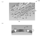
- the strut 16 has a laminated structure as shown in FIG. That is, in the strut 16 of the present embodiment, the core decomposition control layer 20a is laminated on the inner peripheral surface (the lower surface in FIG. 2) of the core layer 18, and the outer peripheral surface (the upper surface in FIG. 2) of the core layer 18.
- the core decomposition control layer 20b is laminated.
- the core layer 18 is formed of a biodegradable material that is decomposed and absorbed in a predetermined period by a living tissue constituting a body lumen, and is formed of a biodegradable resin in this embodiment.
- the biodegradable resin material forming the core layer 18 is not particularly limited as long as it is a biodegradable material that is decomposed and absorbed by a living body and is a biocompatible material that has a small influence on the living body when placed in the body.
- PLLA poly-L-lactic acid
- polycaprolactone polyglycolic acid
- copolymer or composite thereof is suitably employed, and PLLA is employed in this embodiment.
- the core decomposition control layer 20 is made of a biodegradable material, and in this embodiment is made of a biodegradable metal.
- the biodegradable metal material forming the core decomposition control layer 20 is not particularly limited as long as it has both biodegradability and biocompatibility.
- Mg, Ca, Zn, Li, Fe, or their main components are used.
- An alloy or the like is preferably employed, and an Mg alloy is employed in the present embodiment.
- the Mg alloy which is a material for forming the core decomposition control layer 20 is obtained by adding the above-described biodegradable metal elements (except for Mg) and other biocompatible metal elements to the main component Mg. Has been.
- the core decomposition control layer 20a and the core decomposition control layer 20b are formed of the same material, but the materials for forming the core decomposition control layers 20a and 20b may be different from each other.
- the core decomposition control layer 20 a is stacked on the inner peripheral surface of the core layer 18, and the core decomposition control layer 20 b is stacked on the outer peripheral surface of the core layer 18.
- core decomposition control layers 20a and 20b are laminated so as to cover substantially the entire surfaces of the core layer 18.
- the core decomposition control layers 20a and 20b are preferably porous structures having a large number of fine voids penetrating in the thickness direction, whereby the surface of the core layer 18 is microscopically. It is desirable that the core decomposition control layers 20a and 20b are exposed to the outside through gaps.
- the stent 10 having the struts 16 having such a laminated structure is produced by integrally forming a plurality of annular portions 12 and link portions 14 each formed of the struts 16 by thermal spraying.
- the sprayed particles of the material that has been melted or brought close to it by heating are sprayed onto a base material that has been masked corresponding to the peripheral wall structure of the stent 10, so that a large number of the sprayed particles have a predetermined shape.
- the stent 10 can be formed by solidifying.
- the entire skeleton of the stent 10 is integrally formed, and the laminated structure shown in FIG. 2 is applied not only to the annular portion 12 but also to the link portion 14.
- the laminated structure of the core layer 18 and the core decomposition control layers 20a and 20b as shown in FIG. 2 does not have to be applied to the entire skeleton.
- several annular portions 12 have such a laminated structure and other structures.
- the annular portion 12 may have a single layer structure made of one kind of biodegradable material, or the link portion 14 may have a single layer structure.
- the stent 10 of the present embodiment has a laminated structure, it is manufactured through the following processes, for example. That is, first, sprayed particles of Mg alloy are sprayed on the base material, and the inner core decomposition control layer 20a is spray-formed, and then sprayed particles of PLLA are sprayed on the surface of the core decomposition control layer 20a. 18 is formed by thermal spray molding. Finally, sprayed particles of Mg alloy are sprayed on the surface of the core layer 18 to form the outer core decomposition control layer 20b, whereby the stent 10 in which the core decomposition control layers 20a and 20b are laminated on both surfaces of the core layer 18. Is formed.
- spray forming by various known methods such as flame spraying, high-speed flame spraying, and explosion spraying can be employed.
- cold spray molding is also possible, in which the thermal spray material is plastically deformed into a film or a layer by colliding the thermal spray material with a solid layer at a high speed without being melted or close to the state by heating.
- the forming material (spraying material) of the core layer 18 and the core decomposition control layers 20a and 20b to be formed it can be adopted as one of the spray forming methods of the stent 10.
- the stent 10 of the present embodiment having the above-described structure can be expanded and contracted in the radial direction, and is mechanically reduced in diameter from a state before contraction shown in FIG. 1 to a predetermined size.
- the diameter-reduced stent 10 is delivered to, for example, a stenosis site of a blood vessel by a delivery catheter or the like.
- the stent 10 is mechanically expanded by a balloon catheter or other mechanical device, or when the stent 10 is formed of a shape memory material, it is automatically expanded by releasing it from the delivery catheter. In the state shown in FIG. 1, it is placed in a body lumen such as a blood vessel.
- the stent 10 when the stent 10 according to the present invention is inserted into a lumen such as a blood vessel, the stent 10 is deformed from its initial shape and is delivered by a catheter.
- the balloon 10 is expanded using the balloon so that the stent 10 is placed in a state of being pressed against the inner peripheral surface of the blood vessel. It is automatically expanded when released. It is also possible to have an almost initial shape in such an expanded state. In this case, the shape in the expanded state is stably expressed, and strain and residual stress in the expanded indwelling state are also generated. Effectively suppressed.
- the present invention is not limited to such an embodiment, and can be formed with an initial shape having a diameter different from the shape at the time of indwelling.
- the stent 10 formed of the biodegradable material keeps the narrowed portion of the body lumen in the expanded state for a necessary period, and a predetermined period has elapsed. After that, by being decomposed and absorbed by body tissues such as blood vessel walls, the indwelling in the body is eliminated.
- the surface of the core layer 18 is covered with the core decomposition control layers 20a and 20b, and the time required for the decomposition absorption of the core layer 18 is controlled by the core decomposition control layers 20a and 20b.
- the core decomposition control layers 20a and 20b are made of an Mg alloy, and the biodegradation speed of the core decomposition control layers 20a and 20b is made slower than that of the core layer 18 formed of PLLA. Therefore, the core decomposition control layers 20a and 20b covering the surface of the core layer 18 act so as to suppress the decomposition of the core layer 18 in the body for a relatively long period of time, so that the stent 10 is set for a predetermined period. It is easy to adjust the period required for the decomposition so that it is left without being decomposed.
- hydrogen ions generated during biodegradation of the core decomposition control layers 20a and 20b formed of Mg alloy are combined with hydroxide ions generated during biodegradation of the core layer 18 formed of PLLA to generate water. This prevents hydrogen ions generated during the decomposition of the core decomposition control layers 20a and 20b from adversely affecting the body tissue, thereby realizing a less invasive stent placement.
- the thickness dimensions of the core layer 18 and the core decomposition control layers 20a and 20b and the roughness of the porous core decomposition control layers 20a and 20b are determined according to a predetermined period required for biodegradation of the stent 10. In consideration of the above, it is desirable that the neutralization reaction at the time of biodegradation of the core layer 18 and the core decomposition control layers 20a and 20b is appropriately set. This is because if only one of the core layer 18 and the core decomposition control layers 20a and 20b is decomposed first, the remaining biodegradation reaction may affect the body tissue. As is clear from the above, it is desirable that the combination of the forming materials of the core layer 18 and the core decomposition control layers 20a and 20b is selected so that the influence of the biodegradation reaction on the body tissue is reduced.
- the core decomposition control layers 20a and 20b are made porous, the core layer 18 covered with the core decomposition control layers 20a and 20b is biodegraded at a certain rate by the body tissue. It has become. Thereby, prior to the core layer 18, only the core decomposition control layers 20a and 20b are hardly biodegraded.
- the core layer 18 and the core degradation control layers 20a and 20b are laminated to form a multilayer structure, thereby eliminating the narrowing of the body lumen. It is possible to achieve a high degree of avoiding restenosis.
- the material for forming the core layer and the core decomposition control layer and the specific structure of the core layer and the core decomposition control layer are not construed as limited to those of the first embodiment. .
- FIG. 3 shows a cross section of the strut 22 constituting the stent according to the second embodiment of the present invention.
- the struts 22 have the same laminated structure as the struts 16 of the first embodiment.
- the core disassembly control layer 26a is laminated on the inner peripheral surface of the core layer 24, and the core disassembly control is performed on the outer peripheral surface.
- the layer 26b is stacked. Also in the present embodiment, both the inner peripheral surface and the outer peripheral surface of the core layer 24 are covered with the core decomposition control layer 26.
- the core layer 24 is formed of an Mg alloy, and the core decomposition control layers 26a and 26b are formed of PLLA.
- the core layer 24 may be formed of a biodegradable metal, and the core decomposition control layers 26a and 26b may be formed of a biodegradable resin.
- the core layer 24 which is the main part of the stent is formed of a metal material, so that the stent after placement is more firmly maintained in an expanded shape, and the stenotic site of the body lumen is pushed and expanded. Can be kept stable.
- the core decomposition control layers 26a and 26b which are outer layers, are formed by a polymer supporting the drug. It is also possible to efficiently release thrombus and prevent inflammation of the blood vessel wall.
- the ratio of the thickness dimension of the core decomposition control layers 26a and 26b to the core layer 24 is set to be higher than that in the first embodiment. It is desirable to enlarge it.
- FIG. 4 shows a cross section of a strut 28 constituting a stent as a third embodiment of the present invention.
- the core layer 30 has a multilayer structure.
- the core layer 30 has an inner peripheral metal layer 34a stacked on the inner peripheral surface of the central resin layer 32, an outer peripheral metal layer 34b stacked on the outer peripheral surface, and the inner periphery of the inner peripheral metal layer 34a.
- the inner peripheral resin layer 36a is laminated on the surface
- the outer peripheral resin layer 36b is laminated on the outer peripheral surface of the outer peripheral metal layer 34b.
- the core layer 30 of the present embodiment is a multilayer structure in which three resin layers formed of PLLA and two metal layers formed of Mg alloy are alternately stacked. Yes.
- the number of layers and the forming material of the core layer 30 having a multilayer structure are merely examples, and are not particularly limited.
- core decomposition control layers 20a and 20b formed of a biodegradable material are laminated on both surfaces of the core layer 30 as in the first embodiment, and the core decomposition control layer 20a is an inner peripheral resin layer. While being fixed to the inner peripheral surface of 36a, the core decomposition control layer 20b is fixed to the outer peripheral surface of the outer peripheral resin layer 36b.
- the strut 28 of the present embodiment has a seven-layer structure in which one core decomposition control layer 20a, 20b is fixed to both surfaces of a five-layer core layer 30, and is formed of an Mg alloy. Metal layers and resin layers formed of PLLA are alternately stacked.
- all the resin layers 32, 36a, and 36b are formed of PLLA, and all the metal layers 20a, 20b, 34a, and 34b are formed of Mg alloy. Different resin materials may be used, and each metal layer may be formed of different metal materials.
- the entire core layer, which is the main portion of the stent, is formed of resin. Compared to the case, the stability of the shape is excellent, and recoil is easily suppressed.
- both surfaces of the strut 28 are covered with thick metal core decomposition control layers 20a and 20b. In comparison, excessive suppression of biodegradation of the core layer 30 can also be avoided. In addition, since both surfaces of the strut 28 are covered with the metal core decomposition control layers 20a and 20b, it is easy to prevent the biodegradation rate of the core layer 30 from becoming too fast.
- the biodegradation rate in the stent 10 of the first embodiment can be easily controlled, and the stent in the second embodiment is excellent in the indwelling state. Shape stability can be realized at the same time.
- a contrast layer 40 may be further provided on the strut 28 of the third embodiment.
- FIG. 5 shows a cross section of a strut 38 constituting a stent according to a fourth embodiment of the present invention.
- the contrast layer 40 is formed of a biocompatible radiopaque material, and a thin film such as Au, Pt, or tantalum can be suitably used.
- the core layer 30 is configured to include four contrast layers 40, 40, 40, 40 laminated on both surfaces of the inner metal layer 34a and both surfaces of the outer metal layer 34b.
- the core decomposition control layer includes four contrast layers 40, 40, 40, and 40 stacked on both surfaces thereof.
- the inner and outer core disassembly control layers also have a multilayer structure.
- the contrast layer 40 is not necessarily required to cover the entire surfaces of the core decomposition control layers 20a and 20b and the metal layers 34a and 34b, and may be partially laminated. Further, in this embodiment, the contrast layer 40 is laminated on both surfaces of the core decomposition control layers 20a and 20b and the metal layers 34a and 34b, but the core decomposition control layers 20a and 20b and the metal layers 34a and 34b are stacked. It may be selectively laminated on only one or several, or may be laminated only on one of the surfaces of the core decomposition control layers 20a and 20b and the metal layers 34a and 34b.
- contrast layer 40 By providing such a contrast layer 40, it becomes easy to confirm the position of the stent in stent placement under fluoroscopy.
- the contrast layer 40 is formed into a plurality of thin layers arranged apart from each other, particularly excellent visibility is exhibited in the overlapping portion of the contrast layers 40 under X-ray fluoroscopy.
- the contrast layer 40 is formed of a material that does not have biodegradability such as Au or Pt
- the decomposition rate of each of the core layer 30 and the core decomposition control layers 20a and 20b formed of the biodegradable material is It can also be adjusted by the contrast layer 40.
- the contrast layer 40 remains in the body tissue even after all the portions of the stent formed of the biodegradable material are decomposed and absorbed, the contrast layer 40 remaining in the body tissue can be confirmed by fluoroscopy. For example, it is possible to grasp the site where the stent is placed in the blood vessel even after the stent body is decomposed and absorbed.
- the contrast layer 40 has excellent biocompatibility and is formed of Au or Pt, which is a stable material, and is sufficiently thin, so restenosis or the like does not pose a problem.
- FIGS. 6 to 9 show other embodiments of stents 50, 60, 62, and 68 in which the shape after placement can be highly adapted to the shape of the stenosis site in the body lumen. Has been.
- FIG. 6 shows a stent 50 as a fifth embodiment of the present invention.
- the stent 50 has a cylindrical shape that extends substantially linearly before placement, and, like the stent 10 of the first embodiment, a plurality of annular portions 52 are arranged side by side in the axial direction, and the shaft 50 By connecting the annular portions 52 and 52 adjacent to each other in the direction by the link portion 54, a cylindrical skeleton is formed.
- members and portions that are substantially the same as those in the first to fourth embodiments are denoted by the same reference numerals in the drawings, and the description thereof is omitted.
- FIG. 6 shows the stent 50 housed in the delivery catheter in a reduced diameter state
- (b) shows the stent 50 placed in the body lumen.
- the stent 50 has a plurality of self-expanding regions 56 and a plurality of overdeformed regions 58.
- the stent 50 has a plurality of self-expanding regions 56 and a plurality of overdeformed regions 58.
- five self-expanding regions 56 arranged in the axial direction are provided, and overdeformation regions 58 are provided between the self-expanding regions 56 in the axial direction.
- the self-expanding region 56 is formed of a metal material having a shape memory effect, and is released from a delivery catheter accommodated in a reduced diameter state, so that the self-expanding region 56 is automatically shaped in advance by superelasticity (during molding). The shape is restored and expanded.
- Each self-expanding region 56 includes two annular portions 52a and 52a that are adjacent in the axial direction, and a plurality of link portions 54a that connect them, and the annular portions 52a and 52a and a plurality of links.
- the portion 54a is integrally formed of a shape memory material.
- the material for forming the self-expanding region 56 is not particularly limited as long as it is a biocompatible superelastic material. For example, various alloys such as a NiTi alloy are preferably used.
- the over-deformation region 58 is provided in a portion that is off the self-expanding region 56 in the axial direction, is formed of a metal material that does not have a shape memory effect, and is released from a delivery catheter accommodated in a reduced diameter state. After that, it can be mechanically expanded by a balloon or the like. Further, the excessive deformation region 58 can be deformed to be larger than the self-expanding region 56 by adjusting the force exerted by the balloon or the like. It can be extended in the axial direction larger than the expansion region 56.
- the material for forming the over-deformed region 58 is not particularly limited as long as it is a biocompatible material and can be easily deformed by a balloon or the like.
- stainless steel (SUS316L), CrCo alloy, tantalum Etc. can be suitably employed.
- Each over-deformed region 58 includes two annular portions 52b and 52b adjacent in the axial direction and a link portion 54b that connects them, and the annular portions 52b and 52b and the link portion 54b are described above. It is formed with the following materials.
- the annular portion 52a and the annular portion 52b have substantially the same shape in the molded state and have different forming materials, and the annular portion 52 includes two types of annular portions 52a and 52b that are different in forming material.
- the link portion 54a and the link portion 54b are also formed of different forming materials having substantially the same shape
- the link portion 54 is composed of two types of link portions 54a and link portions 54b having different forming materials.
- the self-expanding region 56 and the hyperdeformed region 58 may be covered with a thin layer such as radiopaque Au, Pt, or Ta so that the visibility of the stent 50 can be seen under fluoroscopy. Is improved.
- a thin layer such as radiopaque Au, Pt, or Ta
- the stent 50 of the present embodiment expands into a bent shape so as to correspond to the bent blood vessel, the bending direction in the expanded state of the stent 50 can be grasped under fluoroscopy. For example, it is desirable to provide an X-ray marker indicating the bent inner peripheral side.
- the stent 50 is formed by providing the self-expanding regions 56 and the excessively deforming regions 58 alternately and continuously in the axial direction. That is, both end portions in the axial direction of the stent 50 are self-expanding regions 56, and overdeformation regions 58, 58, 58, 58 and self-expanding regions 56 are formed inside the self-expanding regions 56, 56 constituting the both end portions. , 56, 56 are alternately arranged.
- the self-expanding region 56 and the overdeformed region 58 of this embodiment are integrally formed by means such as spraying, vacuum deposition, etching, electroforming, etc., but are fixed to each other by welding after being formed separately. May be.
- the stent 50 having such a structure is accommodated in a delivery catheter in a reduced diameter state shown in FIG. 6A, and is carried to a stenotic site of a body lumen by the delivery catheter, and then from the delivery catheter. It is released and placed at the stenosis site in the body lumen.
- the stent 50 of the present embodiment is applied when the stenosis portion of the body lumen is curved or bent, and as shown in FIG. 6B, the bent or bent corresponding to the body lumen. Detained in shape. That is, when the stent 50 is placed in a curved or bent stenosis site, the self-expanding region 56 is automatically expanded by superelasticity and pressed against the inner wall of the body lumen, and the The deformation or bending of the stent 50 is adjusted according to the shape of the body lumen. Further, the hyperdeformed region 58 is allowed to deform larger than the self-expanding region 56 and can be shaped by a balloon or the like after releasing the stent 50 from the delivery catheter.
- the shape of the stent 50 can be adjusted after the expansion deformation of the self-expanding region 56 to be more adapted to the shape of the body lumen.
- FIG. 6B shows an example in which the left part of the over-deformed region 58 in the figure is deformed to be larger than the right part in the figure so that the curved shape is inclined to the right in the figure as it goes to both ends in the axial direction.
- region 58 is not limited to this.
- the stent 50 of the present embodiment that expands into a curved or bent shape is particularly effective for highly curved or bent portions of, for example, a blood vessel of a patient who has advanced arteriosclerosis.
- the stenosis part of the body lumen when the stenosis part of the body lumen is hard enough not to be expanded in the self-expanding region 56, the stenosis part can be expanded by balloon expansion of the hyperdeformation region 58.
- the stenosis part When the stenosis part is pushed and expanded by balloon expansion of the over-deformation region 58, if the restriction by the stenosis part is released and the self-expansion area 56 is expanded, the stenosis part is supported by the self-expansion area 56 and stenosis by recoil is performed. Is avoided.
- the over-deformed region 58 that is covered and formed of SUS is relatively easily deformed by the action of an external force, as is understood from allowing expansion by a balloon, but the self-formed region formed of NiTi alloy. This is because the expansion region 56 exhibits expansion deformation due to transformation from the martensite phase to the parent phase, and exhibits high deformation rigidity after expansion.
- FIG. 7 shows a stent 60 as a sixth embodiment of the present invention.
- the stent 60 has a linear cylindrical shape as a whole, and has an intermediate portion as a self-expanding region 56 and both end portions as an overdeformed region 58.
- (a) shows the stent 60 housed in the delivery catheter in a reduced diameter state
- (b) shows the stent 60 in a state of being placed in the body lumen. .
- both the self-expanding region 56 and the over-deformed region 58 are reduced in diameter, and as shown in FIG. It has a constant outer diameter.
- the stent 60 carried to the stenosis portion of the body lumen by the delivery catheter is placed in an expanded state as shown in FIG. That is, in the stent 60 released from the delivery catheter, the self-expanding region 56 automatically expands and deforms to expand the wall portion of the stenosis site, and the over-deformation regions 58 at both ends have the expanded self-expanding region.
- the diameter is expanded and deformed by a balloon so as to have a larger diameter than 56.
- the overdeformed region 58 is deformed into a tapered shape having a diameter that increases outward in the axial direction, and both ends of the overdeformed region 58 are stabilized against the inner wall of the body lumen. To be pressed.
- both ends of the stent 60 are easily brought into close contact with the inner wall of the body lumen, thrombus formation due to blood flow disturbance at both ends is reduced or avoided, and restenosis or the like is performed. Can be avoided.
- both ends of the stent 60 are constituted by the hyperdeformed region 58 and can be deformed later by a balloon in accordance with the shape of the body lumen, the stent 60 is securely attached to the blood vessel wall or the like. While being able to indwell in a more stable state, the formation of thrombus can be suppressed.
- FIG. 8 shows a stent 62 as a seventh embodiment of the present invention.
- the stent 62 has a structure in which a hyperdeformed region 58 is provided at the distal end (lower end in FIG. 8) of the self-expanding region 56.
- FIG. 8A shows a state where the stent 62 is accommodated in the delivery catheter 64.
- B shows a state in which the self-expanding region 56 of the stent 62 is accommodated in the delivery catheter 64 and the over-deformed region 58 is released from the delivery catheter 64.
- C shows an indwelling state in which the stent 62 is released from the delivery catheter 64.
- the stent 62 accommodated in the delivery catheter 64 is transported to the stenosis part of the body lumen, and then, as shown in FIG. While housed in the delivery catheter 64, the distal end hyperdeformed region 58 is released from the delivery catheter 64 and is expanded by the balloon catheter 66. As a result, the hyperdeformed region 58 is pressed against the inner wall surface of the body lumen, and the stent 62 is positioned with respect to the body lumen.
- the delivery catheter 64 and the balloon catheter 66 are not requirements for configuring the present invention, but are shown in FIGS. 8A and 8B for the purpose of facilitating understanding.
- the self-expanding region 56 is released from the delivery catheter 64 and is pressed against the constriction portion of the body lumen by self-expansion based on superelasticity. It is expanded by the stent 62.
- a distal force acts on the stent, and the placement position may be shifted due to jumping.
- the stent 62 of the present embodiment is positioned with respect to the body lumen by the pre-expanded hyperdeformed region 58, jumping can be prevented from occurring when the self-expanding region 56 is released.
- FIG. 9 shows a stent 68 as an eighth embodiment of the present invention.
- the stent 68 has a self-expanding region 56 at both ends in the axial direction and an over-deformed region 58 at the intermediate portion.
- the stent 68 has a tubular skeleton formed by a part of the wall portion of the skeleton constituting the over-deformed region 58 being expanded by a balloon or the like.
- a branch opening 69 that opens to the side is formed in a part of the wall. More specifically, in the stent 68 of the present embodiment, a balloon is inserted between the axial directions of the adjacent annular portions 52a and 52b, and the gap between the annular portions 52a and 52b is expanded by the balloon.
- the over-deformed region 58 is deformed larger than the self-expanding region 56 to form a branch opening 69 that penetrates the peripheral wall portion of the skeleton.
- the stent 68 can be suitably used as a stent to be placed in the branch portion of the blood vessel.
- the branch opening 69 is formed by the post-deformation of the hyperdeformed region 58 by the balloon in a state where the stent 68 is positioned with respect to the body lumen by the deformation of the self-expanding region 56, The shape can be more accurately matched to the branch portion of the blood vessel.
- another stent can be inserted into the branch vessel through the branch opening 69 after the stent 68 is placed.
- the branch opening 69 is formed between the axial directions of the adjacent annular portions 52a and 52b.
- the branch opening 69 is formed between the axial directions of the adjacent annular portions 52b and 52b. It can also be formed.
- the branch opening 69 may be formed by deforming the annular portion 52b so as to expand in the axial direction, or the branch opening 69 can be formed by expanding the annular portion 52b in the circumferential direction.
- the structure is not limited to the structure in which the core decomposition control layers 20 and 26 are laminated on the entire surface of the core layers 18, 24 and 30. It may be partially provided on the surface of the core layers 18, 24, 30.
- the core decomposition control layers 20 and 26 may be formed only on the surface of any one of the core layers 18, 24 and 30.
- the core layer 18 is formed of a biodegradable metal, or the core decomposition control layers 20a and 20b are formed of a biodegradable resin. It may be formed of a degradable resin or a biodegradable metal.
- the core layer and the core decomposition control layer may be formed of the same material, but are preferably formed of different materials. For example, even when both the core layer and the core decomposition control layer are formed of an Mg alloy, the core layer and the core are made different by changing the kind of metal element added to Mg, which is the main component, and the proportion of the metal element. It is desirable to impart suitable characteristics to the decomposition control layer.
- the core layer and the core decomposition control layer have a laminated structure like the core layer 30 of the third and fourth embodiments, the production as in the third and fourth embodiments is performed.
- the structure is not limited to a structure in which a degradable resin layer and a biodegradable metal layer are alternately arranged, and a multi-layer core layer (core decomposition control layer) may be formed of a plurality of types of biodegradable resin layers. Further, it may be composed of a plurality of types of biodegradable metal layers. Note that both the core layer and the core decomposition control layer may have a multilayer structure.
- the contrast layer 40 as in the fourth embodiment may be provided.
- the contrast layer 40 may be formed of a single material having excellent contrast properties such as Au and Pt.
- the contrast material is mixed with the biodegradable material substantially uniformly and sprayed (co-spray).
- the core layers 18 and 24 and the core decomposition control layers 20 and 26 can also be formed so as to serve as a contrast layer.
- the self-expanding region 56 and the over-deformed region 58 are arranged at different positions in the axial direction. For example, their arrangement can be changed as appropriate.
- an appropriate shape such as embossing may be attached to the surface of the stent, and when the stent is produced by thermal spraying, by appropriately setting the shape of the base material or mask used for thermal spraying.
- An appropriate shape such as embossing can be easily formed on the surface.
- it can be effectively used as a drug-eluting stent. That is, for example, by applying or depositing a drug that suppresses cell growth or a resin layer containing such a drug on the outer peripheral surface of a stent with irregularities, the drug can be eluted from the blood vessel wall. it can. At that time, the wettability is improved by such unevenness, and the applied drug or the resin layer can be easily attached to the outer peripheral surface of the stent and can be made difficult to peel off.
- a medicine containing recess 70 for containing medicine may be formed in the skeleton of the stent, that is, the annular portion 12 and the link portion 14.
- the stent is formed by thermal spraying or electroforming, for example, by treating the surface of the molding base (base material) with a protrusion or the like, the inner surface of the stent formed on the surface is processed.
- a recess having a size corresponding to the peripheral surface can be transferred and formed.
- a peripheral wall surrounding the island-shaped mask portion is formed, and the central mask portion It is also possible to form a recess opening in the outer peripheral surface of the stent.
- a medicine receiving recess 70 can be formed in any shape and size, and other than the groove shape extending in the length direction of the annular portion 12 and the link portion 14 as shown in FIG. It may be a hole such as a circle.
- the stent is formed by electroforming, for example, using a eutectoid plating technique using an electrolytic solution in which a non-conductive powder is dispersed, a porous structure or microporous corresponding to the eutectoid fine particles is used. It is also possible to give the structure to the annular part 12 and the link part 14.
- the amount of metal constituting the stent can be reduced.
- a drug-eluting stent as described above can be formed, and the drug can be effectively eluted into the blood vessel wall.
- the drug containing recess 70 formed in the stent may be not only a bottomed shape but also a through hole.
- the through hole in the stent in this way, the loading of the drug can be further facilitated and the amount of the drug loaded can be increased.
- the through-hole becomes hollow after the drug or the like is eluted, blood can pass through the through-hole. For example, blood flow is inhibited as compared with the case where the recess is bottomed. Therefore, the effect of preventing turbulent flow and restenosis can be exhibited.
- the medicine may be directly placed in the medicine housing recess 70, for example, a biodegradable resin cotton impregnated with the medicine or a capsule filled with the medicine is placed in the medicine housing recess 70. Also good.
- the unevenness formed on the stent may be formed directly on the surface of the stent.
- a convex portion on the surface of the stent, a relatively concave portion is formed. May be.
- the stent 10 may be provided with an ultrasonic marker 72 as shown in FIG.
- the ultrasonic marker 72 is made of resin or metal, and has a large number of minute voids 74 therein.
- the minute voids 74 contain a gas such as air.
- the ultrasonic marker 72 is excellent under the fluoroscopic perspective because the irradiated ultrasonic wave is reflected at the boundary between the solid part formed of resin or metal and the gas phase of the minute gap 74. Visibility is demonstrated.
- the microscopic voids 74 of the ultrasonic marker 72 may have a porous structure that is continuous to some extent, but it is desirable that the microscopic voids 74 be made of a liquid such as blood. It becomes difficult to satisfy, and high visibility under ultrasonic fluoroscopy can be maintained for a long time.
- the minute gap 74 does not necessarily need to be filled with gas, and may be filled with a liquid, or an individual made of a material different from the solid portion may be accommodated.
- the ultrasonic marker 72 is formed by thermal spray molding, for example.
- the spraying density of spray particles is set to be small during spray forming, a relatively large number of pores and a coarse spray coating is formed.
- the ultrasonic marker 72 having the minute gap 74 can be easily formed.
- thermal spray molding it is possible to select a molding material from a wide range of resin materials and metal materials, and a molding material that takes into account the required characteristics such as biodegradability and biocompatibility can be selected with great flexibility. can do.
- the method of forming the ultrasonic marker 72 is not limited to thermal spraying, and can be formed by etching in addition to vacuum deposition and electroforming, which are the same film formation techniques as thermal spraying.
- FIG. 12 shows a covered stent 76 used as a flow diverter or a stent graft.
- the covered stent 76 has a structure in which a stent main body 80 composed of a plurality of annular portions 78 arranged away from each other in the axial direction is fixed to the outer peripheral surface of a cylindrical cover 82 formed of a resin thin film such as PTFE. Has been.
- the annular portion 78 has a shape that extends in the circumferential direction while undulating in the axial direction, and has at least one of self-expandability by superelasticity and mechanical expandability using a balloon stent or the like. I have.
- the ultrasonic marker 72 of this embodiment is integrally fixed to the surface of the stent body 80 or the surface of the cover 82, for example. This improves the visibility of the covered stent 76 under ultrasonic fluoroscopy, and makes it easier to grasp the position of the covered stent 76 in the stent placement under echo.
- the ultrasonic marker 72 can be applied to a stent that does not have the cover 82, such as the stent retriever 84 shown in FIG.
- the stent retriever 84 is a cylindrical mesh-type stent-type thrombectomy device, for example, for pressing and removing a thrombus with a net to remove it.
- the entire skeleton has a structure including the minute gap 74, and the skeleton itself is the ultrasonic marker 72.
- the ultrasonic marker 72 is not limited to the one provided on the surface of the stent, and for example, the entire skeleton of the stent may be the ultrasonic marker 72.
- the microvoids 74 are continuously penetrating into the surface so that the blood contact area with the blood vessel wall becomes large and less invasive.
- the indwelling position can be stabilized by fine surface roughening.
- the ultrasonic marker 72 as described above is not necessarily applied only in an aspect combined with the present invention, and can be applied to, for example, a medical device other than a stent.
- the present invention can be applied to a catheter 86 as shown in FIG. 14, a coil 88 for stagnating the blood flow of an aneurysm as shown in FIG. 15, a guide wire used for introducing a catheter, and the like.
- the ultrasonic marker 72 is improved in visibility even when the position is confirmed using, for example, IVUS (intravascular ultrasound), and the position is easily grasped.
- IVUS intravascular ultrasound
- the invention relating to the ultrasonic marker 72 can also be recognized as an independent invention that can solve a different problem from the present invention.
- the first aspect of the present invention is a medical device to be inserted into a body lumen, comprising an ultrasonic marker formed of a sparsely structured structure having a minute gap inside, and the ultrasonic marker. Is formed by at least one of thermal spraying, vapor deposition, etching, and electroforming.
- the second aspect is the medical device according to the first aspect, wherein at least one of a catheter, a stent, a coil, and a thrombus collection device provided with the ultrasonic marker is used.
- a third aspect is a stent having a cylindrical skeleton that can be expanded and contracted in the medical device according to the first or second aspect, wherein the skeleton is the ultrasonic marker.
- the shape of the stent is not limited to a simple straight shape as illustrated in the above embodiment or a shape in which a thick portion is provided at an end or center in the length direction, but a tapered cylindrical shape, Thick end shape, Y-shaped branch shape including a main cylinder portion and a branch cylinder portion, a shape in which the diameter of the main cylinder portion and the branch cylinder portion are different in the Y-shaped branch shape,
- the present invention is applicable to various types of irregularly shaped stents, such as at least one having a tapered cylindrical shape and a shape partially tapered in the length direction.
- the rigidity of both end portions in the axial direction of the stent may be increased by making the both end portions in the axial direction of the stent thick or adopting a metal having high rigidity as both end portions in the axial direction. According to this, lifting from the blood vessel at both axial end portions of the stent is suppressed, and the stent is stably placed at the stenosis site of the blood vessel. In particular, since the lift from the blood vessel is suppressed at both axial ends of the stent, the risk of thrombus formation due to blood flow disturbance is reduced, and restenosis can be effectively prevented.
- the cross-sectional shapes of the annular portion 12 and the link portion 14 may be different in the skeleton of the stent 10.
- the link portion is not essential, and the annular portions adjacent in the axial direction of the stent may be continuously connected in a spiral structure. In this case, there is no need to provide a link portion, and the skeleton of the stent can be formed without the link portion.
- the stent having the self-expanding region 56 and the over-deformed region 58 as shown in the fifth to eighth embodiments is formed in a structure in which the struts are spirally continuous, the struts in the length direction To form a stent with a self-expanding region 56 partially in the axial direction.
- the thickness dimension and cross-sectional shape of the strut need not be uniform over the entire length.
- it may be partially thick or thin in the length direction of the strut.
- a weak part may be formed of the thin part of the strut.
- a stent having a structure according to the present invention may be formed by electroforming or vacuum deposition known as a molding technique such as film formation as well as thermal spraying.
- a molding technique such as film formation as well as thermal spraying.
- a molded base is immersed in an electrolytic bath in which a predetermined metal is ionized to form a stent by electrodepositing metal ions and integrating them into a predetermined shape, or particles of a material that is vaporized or sublimated by heating. It is also possible to form a stent by integrating a large number of these into a predetermined shape. Even when the stent is formed by electroforming or vacuum deposition, it can be easily manufactured by appropriately masking the surface of the molding base. It is also possible to form a stent with a predetermined shape by etching. That is, a stent can be formed by removing unnecessary portions of a cylindrical body made of a predetermined material with a chemical solution or an active group by gas discharge.
- stents 90, 104, 106, 108, 110, and 112 that can be recognized as independent inventions that can solve problems different from the present invention.
- These stents 90, 104, 106, 108, 110, 112 are formed by, for example, the above-described spraying, vapor deposition, etching, electroforming, or the like.
- the stent 90 shown in FIG. 16 includes a substantially cylindrical shape and a trunk cylinder portion 92 and a branch cylinder portion 96 that extend linearly, and a branch portion provided at an intermediate portion in the length direction of the trunk cylinder portion 92.
- the branch cylinder portion 96 is inclined to the side from 94 and extends to have a substantially Y-shaped branch shape.
- the number of tube portions is different in the length direction (vertical direction in FIG. 16) by the branch portion 94, that is, the stent 90 has a cross-sectional shape in the length direction. It is an irregularly shaped cylinder shape that changes.
- Each of the trunk tube portion 92 and the branch tube portion 96 is provided with a plurality of annular portions 98 that are continuously curved in the circumferential direction and repeatedly bent or bent in a wavy shape with a predetermined distance from each other in the axial direction.
- a series of struts 102a constituting the trunk cylinder portion 92 and a series of struts 102b constituting the branch cylinder portion 96 are formed.
- the annular parts 98 and 98 adjacent to each other in the axial direction in the struts 102a and 102b are respectively connected by the link parts 100 extending in the substantially axial direction, thereby forming a cylindrical shape having a predetermined length.
- the annular portion 98 that constitutes the basic cylinder portion 92 and the annular portion 98 that constitutes the branch cylinder portion 96 are continuous on the circumference of the basic cylinder portion 92 and the branch cylinder portion 96. It extends.
- the integral structure of each strut 102a, 102b is implement
- the skeleton of the stent 90 of the present embodiment is configured by connecting the annular portions 98 and 98 adjacent in the axial direction by the link portion 100.
- the specific shapes of the annular portion 98 and the link portion 100 are not limited in the present invention, and the wave shape of the annular portion 98 and the connection by the link portion 100 are considered in consideration of the characteristics required for the stent 90. A part, the number of the link parts 100 on the periphery of the annular part 98, etc. can be set suitably.
- the width dimension and the thickness dimension of the annular portion 98 and the link portion 100 are not particularly limited, but the strut 102 constituting the annular portion 98 is about 30 to 200 ⁇ m for the purpose of ensuring the strength.
- the width dimension and the thickness dimension are desirable, and the link portion 100 is desirably a width dimension and a thickness dimension of about 10 to 100 ⁇ m.
- Such a branched stent 90 is produced by integrally forming a plurality of annular portions 98 and link portions 100 constituting the strut 102 by electroforming.
- a molding base having the shapes and sizes of the target basic cylinder portion 92 and the branch cylinder portion 96 is prepared by using a conductor such as stainless steel. Then, on the surface of the molding base, an exposed surface is formed in a shape corresponding to each of the plurality of annular portions 98 and the link portions 100, and a non-conductive mask is applied to other regions. Then, it is immersed in an electrolytic bath in which a predetermined metal is ionized, and metal ions are electrodeposited on the exposed surface of the molding base to perform electroforming. After obtaining a metal having a predetermined thickness, the mask 90 is removed, and the molded base is extracted or dissolved to obtain the stent 90 having the above-described target structure.
- a conductor such as stainless steel.
- the stent 90 of this embodiment having the above-described structure is capable of expanding and contracting in the radial direction in the trunk cylinder portion 92 and the branch cylinder portion 96, and has a predetermined dimension from the state before contraction shown in FIG. The diameter is reduced mechanically.
- the stent 90 is delivered to, for example, a stenosis site of a blood vessel by a delivery catheter or the like. Thereafter, the stent 90 is expanded by a balloon catheter, or when the stent 90 is formed of a shape memory material, the stent 90 is automatically expanded by being released from the delivery catheter, and in the state shown in FIG. Etc. are placed in the body lumen.
- the stent 90 of this embodiment is manufactured by electroforming, a branched shape having a trunk cylinder portion 92 and a branch cylinder portion 96 can be integrally formed. Therefore, compared to the case where two stents obtained by laser processing straight cylindrical metal fittings as in the conventional structure are joined to form a branched shape, the portion to be excised can be reduced, The yield can be improved and a complicated branch shape can be obtained with high accuracy. Therefore, it is possible to realize the stent 90 with high yield with respect to a complicated shape part such as a blood vessel of a living body with high accuracy.
- the stent 104 as another embodiment having a tapered cylindrical shape whose inner and outer diameter dimensions change in the axial direction is also integrally formed by electroforming with an initial shape of a target taper angle. Can do.
- the stent 104 of the present embodiment has such a tapered shape and a deformed cylindrical shape whose cross-sectional shape changes in the length direction.
- the same members and parts as those in the above-described aspect are denoted by the same reference numerals as those in the above-described aspect, and detailed description thereof is omitted.
- a stent 104 is tapered in an initial shape when placed in a blood vessel or the like whose diameter is changed, distortion and residual stress in the placed state can be suppressed.
- the skeletons of the stents 90 and 104 as described above, that is, the struts 102 and the link part 100 are manufactured by electroforming, it is possible to have a laminated structure of different materials. Specifically, after forming a non-conductive mask on the surface of the molding base as described above and performing the first electroforming, the electroforming is performed in the second electrolytic bath of another metal ion. By performing the casting, a metal layer of another material can be formed on the surface of the metal formed by the first electroforming by the second electroforming. As can be seen from this, the invention of this aspect can be adopted in combination with the inventions according to the first to fourth embodiments. Similarly, the invention of this aspect can be adopted in combination with the inventions according to the fifth to eighth embodiments.
- Such a laminated structure of metals can be performed any number of times, for example, a structure in which a surface layer portion is provided by coating another metal so as to cover a core portion formed of a specific metal is also possible. It is. In that case, for example, it is preferable that the metal of the surface layer portion has a higher ductility than the metal of the core portion. As a result, the followability when the stent is bent is improved, and the concentration of strain and stress in the surface layer portion is avoided.
- the metal in the surface layer portion has a smaller ionization tendency than the metal in the core portion.
- the core portion is formed of stainless steel (SUS316L), CrCo alloy, tantalum, NiTi, etc., while the surface layer portion is Ni, NiCo, Cu, NiW, Pt, Au, Ag, Cr, Zn, etc.
- it can be formed of Au or Pt. Accordingly, it is possible to improve biocompatibility by suppressing the potential difference from the living body with the metal in the surface layer portion while efficiently ensuring strength and rigidity with the metal constituting the core member.
- the ionization tendency of Au, Pt, etc. is very low, metal elution can be suppressed.
- the annular portion 98 and the link portion 100 can be formed of different metal materials, and the material of the annular portion 98 can be partially different in the length direction and the circumferential direction of the stent 90. become.
- the straight cylindrical stent 106 only one or a plurality of annular portions 98 positioned at the axial ends thereof are provided.
- the thickness can be increased by increasing the number of times of electroforming as compared with the other annular portion 98 located in the central portion in the axial direction. That is, in the stent 106 of the present embodiment, the cross-sectional shape changes in the length direction with a shape in which the thickness dimension changes in the length direction.
- the axial end portion may have a larger outer diameter size, a smaller inner diameter size, or both than the central portion. .
- this thick part may be provided in one edge part of an axial direction, and may be provided in an axial direction both ends.
- the rigidity of the axial end portion is made larger than that of the central portion. It is also possible to prevent restenosis by suppressing the lifting from the blood vessel at the axial end while securing the degree of freedom.
- the mask is formed again, and the second electroforming is performed so as to straddle over the annular portions 98 and 98 adjacent to each other located at the end in the axial direction. It is also possible to form an annular portion 98 that is offset by a half pitch in the axial direction so as to cover the outer periphery. Since it is possible to reinforce the rigidity of the axial end portion with such a complicated structure, a large degree of freedom in design is realized.
- the rigidity of the end portion on the outer side in the axial direction is substantially the same as or smaller than that of the central portion at the axial end where the rigidity is increased compared to the central portion. .
- the load which the axial direction terminal part of the stent detained so that it may bite into the blood vessel wall can exert on the blood vessel wall can be reduced.
- Such a rigid end portion can be realized, for example, by forming only the end portion with a soft metal, or by adjusting the number of times of electroforming, a mask or the like to reduce the thickness or width of the end portion.
- FIGS. 19A and 19B show the cross-sectional shape of the strut 102 whose width dimension changes from the inner peripheral surface toward the outer peripheral surface. That is, in the embodiment shown in FIGS. 19A and 19B, the cross-sectional shape of the strut 102 has a deformed structure that changes in the thickness direction.
- the upper side is the outer peripheral side, that is, the side in contact with the blood vessel wall
- the lower side is the inner peripheral side, that is, the side located in the blood vessel lumen.
- a strut 102 having a substantially triangular cross section can also be used.
- the width dimension is reduced from the inner peripheral surface toward the outer peripheral surface, and the side in contact with the blood vessel wall is gradually narrowed. Therefore, when the stent is expanded, the pressing force against the blood vessel wall of the stent is increased. Can be concentrated on the tapered portion of the strut 102. As a result, the blood vessel can be expanded with a smaller pressing pressure of the stent, in other words, with the expansion pressure of the stent.
- the taper portion of the strut 102 bites and breaks against the calcified lesion portion, so that it is difficult to expand with a conventional rectangular cross section.
- Vascularized vessels can also be dilated.
- a strut 102 having a substantially inverted triangular cross section can also be employed.
- the width dimension is reduced from the outer peripheral surface toward the inner peripheral surface, and the side located in the blood vessel lumen is gradually narrowed. It can be suppressed as much as possible.
- the risk of blood clots and the like being generated can be reduced.
- the area exposed to the blood vessel lumen is small, the period until it is covered with the vascular endothelial cells can be shortened, and the strut 102 is buried in the blood vessel at an early stage. From this, the enlargement of the vascular endothelium can be suppressed, and the stent placement portion can be cured in a relatively short period of time.
- the strut 102 having such a shape can be formed by adjusting the shape of the mask during electroforming to a desired shape by etching or the like, and can greatly improve the degree of freedom of setting the cross-sectional shape. That is, a stent whose cross-sectional shape changes in the thickness direction as shown in FIGS. 19A and 19B can be easily manufactured by electroforming only by appropriately setting the masking shape.
- the cross-sectional shape of the strut 102 is not limited to the approximate triangular shape or the generally inverted triangular shape shown in FIGS. 19A and 19B, and for example, a semicircular shape or a double tapered shape is also employed. Can be done.
- the stents 90, 104, and 106 as described above are manufactured by electroforming, the cross-sectional shape of the link portion 100 that connects the annular portions 98 and 98, as well as the degree of freedom in designing the strength and the brittleness are greatly increased. Can be secured.
- the fragile portion applied when the expanded stent is bent is easily deformed or cut, so that the stent has a shape of a body lumen. It is easy to follow.
- an opening is formed in a stent corresponding to a branched blood vessel or the like, an operator can easily perform an operation of cutting or expanding the fragile site.
- the link portion 100 in the stents 90, 104, and 106, in the skeleton, constitutes a weakened portion whose strength is smaller than that of the annular portion 98.
- a link portion 100 by electroforming, only a thin shape in the width direction of the strut 102 can be formed by laser processing of the conventional structure, but not only the thin shape but also the thickness of the strut 102. Thin shapes can also be formed in the vertical direction.
- the cross-sectional shape of the link part 100 was only a simple rectangular cross section by the conventional laser processing, but shapes other than a rectangle can also be formed.
- the position of the link portion 100 in the thickness direction can be appropriately changed with respect to the annular portions 98 and 98.
- the upper side shows the blood vessel wall side
- the lower side shows the blood vessel lumen side. That is, in FIG. 20 (a), the annular portions 98, 98 are connected by the link portion 100 on the blood vessel wall side, while in FIG. 20 (b), the annular portions 98, 98 are the link portions at the central portion in the thickness direction. 100 are connected.
- the annular portions 98 and 98 are connected by the link portion 100 on the blood vessel lumen side.
- the link portions 100 positioned on the blood vessel wall side, the central portion, and the blood vessel lumen side.
- the strut 102 and the link portion 100 are shown as a rectangular cross section, but FIG. 20 simply shows the relative positions of the annular portions 98 and 98 and the link portion 100, and the strut 102 and the link portion 100.
- the shape of is not limited in any way.
- the annular portion and the link portion can only be formed with the same thickness, whereas the stent 90 , 104, 106 are manufactured by electroforming, the thickness dimension of the link portion 100 can be reduced.
- the link part 100 can be formed thinly and thinly, and when the link part 100 is cut
- a method of forming the annular portion 98 and the link portion 100 separately and then fixing them together has been adopted.
- by manufacturing the stents 90, 104, and 106 by electroforming The link part 100 is integrally formed, and manufacturing can be facilitated while ensuring high dimensional accuracy. Furthermore, since the cut surface of the link part 100 is made small, irritation
- the design of the position of the link portion 100 can be changed as appropriate in the width direction of the strut 102, and it can be formed at the end in the width direction with respect to the strut 102, but is shown in FIG.
- the link portion 100 is preferably formed in the center portion in the width direction of the strut 102, that is, in the center portion in the width direction in the bent portion of the annular portion 98 in the above-described embodiment.
- the link portion 100 is preferably located at the central portion of the strut 102 in the thickness direction.
- FIG. 21 also shows the strut 102 and the link portion 100 as a rectangular cross section, but FIG. 21 merely shows the relative positions of the annular portion 98 and the link portion 100.
- the shape is not limited at all.
- FIGS. 22 and 23 show a stent 108 as still another embodiment.
- the stent 108 is generally cylindrical and extends linearly as a whole.
- the cross-sectional shape of the strut 102 in the stent 108 of this embodiment is formed as a deformed structure that is different in the thickness direction (vertical direction in FIG. 19B) as shown in FIG. 19B.
- the width dimension (the dimension in the left-right direction in FIG. 19B) is increased from the inner peripheral surface toward the outer peripheral surface.
- the cross-sectional shape of the strut 102 is a substantially inverted triangle. Further, in this embodiment, the edge portion in the inverted trapezoidal cross-sectional shape shown in FIG. 23B is subjected to chamfering such as sand blasting, chemical polishing, electrolytic polishing, etc., so that it is shown in FIG. 19B. A generally inverted triangular cross-sectional shape is formed.
- W width dimension of the outer peripheral surface
- the central angle ⁇ in the arc of the inner peripheral surface is made smaller than the central angle ⁇ in the arc of the outer peripheral surface of the strut 102 ( ⁇ ⁇ ). That is, two points A and B on the outer peripheral surface where the width dimension is the largest in the cross-sectional shape of the strut 102 before the chamfering process (thick one-dot chain line in FIG. 24) pass through these points A and B.
- An arc Co that is convex to the side and a center of curvature O located on the inner peripheral side of the strut 102 are assumed as the center of curvature of the arc Co.
- the depression angle ⁇ on both side surfaces is made larger ( ⁇ ⁇ ) than the central angle ⁇ in the arc of the outer peripheral surface of the strut 102.
- the depression angle ⁇ is formed by the intersection of the straight line AD and the straight line BE in FIG. 24 in the cross-sectional shape of the strut 102 before the chamfering process.
- the central angle ⁇ of the outer peripheral surface is preferably 1 ° ⁇ ⁇ ⁇ 45 °, and more preferably 4 ° ⁇ ⁇ ⁇ 15 °.
- the central angle ⁇ of the inner peripheral surface is preferably set to 0 ° ⁇ ⁇ ⁇ 30 °, and more preferably set within a range of 0 ° ⁇ ⁇ ⁇ 10 °.
- the depression angle ⁇ on both side surfaces is preferably set to 15 ° ⁇ ⁇ ⁇ 90 °, and more preferably set within a range of 30 ° ⁇ ⁇ ⁇ 90 °.
- the stent 108 according to this embodiment having such a shape is manufactured as a metal skeleton in which the struts 102 and the link portions 100 are integrally formed by electroforming.
- the stent 108 of this embodiment is capable of expanding and contracting in the radial direction.
- the stent 108 is mechanically contracted from a state before contraction shown in FIG. 22 to a predetermined size, and contracted as shown in FIGS. State.
- FIG. 25 shows one of the annular parts 98 constituting the stent 108, and the illustration of the other annular part 98 and the link part 100 connecting the annular parts 98, 98 is omitted.
- the cross-sectional shape of the strut 102 is an approximately inverted triangle as shown in FIG. 19B, and when the diameter is reduced, the circumferential direction in the strut 102 is formed at both axial end portions of the annular portion 98. Adjacent parts abut. At that time, as shown in FIG. 26 (b), the peripheral end portions on the outer peripheral side in the cross-sectional shape of the strut 102 are in contact with each other, so that the diameter of the stent 108 is limited and the diameter of the stent 108 is reduced.
- the outer diameter dimension of the stent 108 is defined.
- the stent 108 of this embodiment having the above-described structure, since the cross-sectional shape of the strut 102 is a substantially inverted triangle, for example, compared to a stent having a conventional structure having a rectangular cross-section, the stent 108 has an internal structure. The part exposed to the peripheral blood flow can be reduced. This prevents the stent 108 from obstructing the blood flow and prevents the blood flow from becoming slow or turbulent (turbulent) due to the stent 108 being placed in the blood vessel. Is done.
- the area exposed from the blood vessel wall is reduced, it is buried in the vascular endothelial cells at an early stage. That is, since the blood vessel wall that has cracked due to the placement of the stent 108 can be healed in a relatively short time, the enlargement of the vascular endothelial cells is suppressed and a thrombus adheres to the enlarged vascular endothelial cells. Thus, restenosis at the indwelling position of the stent 108 can be avoided.
- the stent 108 is not limited in diameter reduction as compared with a stent having a conventional structure, and the outer diameter dimension at the time of diameter reduction can be further reduced.
- the possibility of contact on the inner peripheral side is further reduced, so the outer diameter size at the time of diameter reduction Can be reliably reduced.
- the delivery of the stent 108 and the delivery catheter equipped with the stent 108 can be improved.
- the depression angle ⁇ on both sides is set to 15 ° ⁇ ⁇ ⁇ 90 °, whereby the circumferential dimension in the cross-sectional shape of the strut 102 can be kept small.
- the wave number in the circumferential direction of the stent the number of repeating units in the circumferential direction
- the outer diameter dimension when the diameter is reduced can be stably reduced.
- FIG. 27 shows a stent 110 as still another embodiment.
- the stent 110 of this aspect has a skeleton structure composed of the struts 102 and the link portions 100, and the cross-sectional shape of the struts 102 is the shape shown in FIG.
- the stent 110 of this embodiment has a deformed cylindrical shape in which the outer diameter dimension at both end portions in the axial direction (vertical direction in FIG. 27) is larger than the outer diameter dimension at the central portion in the axial direction.
- the stent 110 of this aspect is, for example, a plurality of annular portions 98 positioned at both axial end portions relative to the straight cylindrical stent 108 shown in FIG. 22 than the annular portion 98 positioned at the axial central portion. Also, it can be formed by increasing the number of times of electroforming to make it thick. That is, it is preferable that the stent 110 of this aspect has a laminated structure made of a plurality of types of metals.
- Such a laminated structure does not need to be formed over the entire stent, and a specific portion of the stent may be a laminated structure.
- the shape of the inner hole of the stent 110 is not limited in any way. For example, a straight shape extending in the axial direction may be used, and both end portions may have larger diameters than the central portion in the axial direction.
- the stent 110 has both end portions in the axial direction being thicker than the central portion in the axial direction, so that the rigidity of both end portions is larger than that in the central portion.
- the cross-sectional shape of the skeleton is the same as that of the stent 108, the same effect as that of the stent 108 can be exhibited.
- both end portions in the axial direction are larger in outer diameter than the central portion in the axial direction and have increased rigidity, the axial end portions of the stent 110 are lifted from the blood vessel. Suppressed and stably placed at the stenosis site of the blood vessel. In particular, when the axial end of the stent is separated from the blood vessel in a state where it is placed in the blood vessel, there is an increased possibility that blood flow is disturbed and a thrombus is formed.
- the lift from the blood vessel is suppressed at both axial ends of the stent 110, so that restenosis at the stent placement position can be more effectively prevented. Furthermore, by reducing the rigidity of the axial end portion, the load exerted on the blood vessel wall by the axial end portion of the stent placed so as to bite can be reduced.
- FIG. 28 shows a stent 112 as another embodiment.
- the stent 112 of this embodiment has a substantially Y-shaped skeleton structure composed of the struts 102 and the link portions 100, and the cross-sectional shape of the struts 102 is the shape shown in FIG.
- the stent 112 of this embodiment may be formed by, for example, forming the main cylinder portion 114 and the branch cylinder portion 116 separately and joining them together by means such as welding. 114 and the branch cylinder part 116 may be formed integrally.
- the stent 112 of this embodiment having such a shape, since the cross-sectional shape of the strut 102 is the same as that of the above-described embodiment shown in FIG. 19, the same effect as the stent 108 of this embodiment is exhibited. obtain.
- the stent 112 according to this embodiment has a branched shape and can correspond to a complicated shape such as a blood vessel of a living body, and blood flow disturbance is suppressed even at the branched portion of the blood vessel, thereby further reducing the restenosis of the blood vessel. It can be effectively prevented.
- Example 1 of this invention a stent 108 having a structure according to the embodiment shown in FIG. 19 shown in FIGS. 22 and 23 was virtually manufactured on a computer. Further, as Example 2 of the present invention, as shown in FIG. 29, a stent 118 is adopted in which the cross-sectional shape of the skeleton is reduced to a width dimension from the inner peripheral surface to the outer peripheral surface to form an approximate triangle. As a comparative example, a stent 120 having a conventional structure with a rectangular cross section as shown in FIG. 30 was adopted, and each was virtually manufactured on a computer.
- Example 2 and the stent 118,120 of a comparative example shown by FIG.29,30 have shown the thing of the shaping
- these stents 108 of Example 1,2 and a comparative example 108, 118 and 120 were prepared assuming that the edge portions were not chamfered.
- FIG. 32 (b) and FIG. 34 (b) when the diameter reduction process is performed, the inner peripheral sides of the skeletons adjacent in the circumferential direction are brought into contact with each other quickly, and further diameter reduction is limited. Is done.
- the stent 108 of Example 1 has a skeleton that is adjacent in the circumferential direction because the width of the inner peripheral surface is smaller than the width of the outer peripheral surface. It is surmised that the diameter reduction is not limited until the outer peripheral sides of the two come into contact with each other, and the outer diameter dimension becomes smaller.
- the outer diameter of the stent 108 of the first embodiment can be made smaller than that of the stent 118 having the substantially triangular cross section of the second embodiment and the stent 120 having the rectangular cross section of the conventional structure. Since the outer diameter at the time of mounting can be reduced, good delivery can be exhibited.
- the velocity distribution in the vicinity of the wall surface is shown by a plane. 35 to 37 are difficult to see because the analysis results output and displayed as colored images are displayed in gray scale for patent application, but the flow is fast in the dark gray part in the figure. On the other hand, the light color portion indicates that the flow is slow, and the flow velocity changes stepwise corresponding to the change from the dark gray portion to the light color portion.
- This analysis was performed using software “ANSYS R14.5” manufactured by ANSYS.
- FIG. 35 (a) has a large and many dark gray vector lines representing a fast flow as a whole.
- the reason why the number of vector lines is small is that the lines are thin and the flow is slow, so that they are not displayed large as vector lines, or there is almost no flow itself. This is because there seems to be no vector line.
- 35 (b) shows many lighter portions as a whole.
- the effect of preventing the occurrence of thrombus due to blood retention and turbulence, and restenosis at the stent indwelling position due to the thrombus adhering to the stent is further enhanced. It is suggested that it can be demonstrated.
- the cross section of the strut 102 of the stent 108 of the first embodiment is a substantially inverted triangle, and therefore, the strut 102 ′ having a cross section of the general triangle as in the second embodiment and a rectangular cross section as in the comparative example.
- the portion protruding to the inner peripheral side can be made smaller, and the inhibition of the flow of fluid passing through the inside of the stent 108 is suppressed as much as possible.
- the cross-sectional shape of the strut 102 ′ is generally triangular, and the inner peripheral sides of the struts contact with each other relatively early. There is a possibility that the outer diameter reduction effect at the time cannot be fully enjoyed. Further, when the stent 118 is indwelled in the lumen, a portion that protrudes from the lumen wall to the inner peripheral side becomes relatively large, and the protruding portion serves as a barrier for the fluid. There is a risk that the flow of
- the outer peripheral side is tapered in the cross-sectional shape of the strut 102 ', and the stent 118 is positioned so that the tapered tip of the stent 118 bites into the lumen wall, thereby effectively positioning the stent 118 in the lumen.
- the stent 118 is positioned so that the tapered tip of the stent 118 bites into the lumen wall, thereby effectively positioning the stent 118 in the lumen.
- a blood vessel wall is hardened like a calcified lesion and the skeleton of the conventional structure has a rectangular cross section, it is difficult to expand the blood vessel. Since the effect of splitting on the lesion site is exerted, a blood vessel that is difficult to expand with a conventional rectangular cross section can be expanded by employing the stent 118 as in the second embodiment.
- a stent having a substantially triangular cross-sectional shape can be suitably employed depending on the condition of the patient and the lesion site.
- the stents 108, 110, 112, and 118 of the present invention have excellent technical significance because the stent corresponding to the state of the stenosis site and the site where the stenosis occurs can be manufactured with a large degree of design freedom. It is what you are doing.
- the problem to be solved by the invention different from the present invention described above depends on the site where the stenosis occurs in the lumen where the stent is placed, the state of the stenosis site, and the like. It is an object of the present invention to provide a stent having a novel structure in which the performance of the stent can be adjusted with a greater degree of design freedom, and the shape corresponding to the lumen of a blood vessel or the like can be realized with a good yield. .
- the skeleton is a metal skeleton formed by at least one of electroforming, etching, spraying, and vapor deposition.
- the skeleton has a cross-sectional shape different from a conventional simple rectangular cross-sectional shape, so that the stenosis occurs in the lumen where the stent is placed, the state of the stenosis, or the like. Accordingly, the stent performance and the like can be adjusted efficiently with a large degree of design freedom.
- the stent since the skeleton is formed by at least one of electroforming, etching, spraying, and vapor deposition, the stent has a shape corresponding to the shape of the lumen from the beginning. Therefore, the portion to be excised can be reduced as compared with the stent manufactured by laser processing, and the stent can be manufactured with a good yield.
- the second aspect of the present invention is the stent according to the first aspect, wherein the cross-sectional shape of the skeleton is such that the width dimension is increased from the inner peripheral surface toward the outer peripheral surface.
- the cross-sectional width dimension of the portion exposed to the fluid in the lumen such as blood can be reduced as compared with the stent having the conventional structure having a skeleton having a simple rectangular cross section. .
- blood or the like can flow more easily in the placement position of the stent in the lumen of a blood vessel or the like than a stent having a conventional structure, and stagnation or turbulence of blood or the like is suppressed.
- troubles such as formation of thrombus and restenosis of the blood vessel at the indwelling position of the stent due to the attachment of the thrombus to the stent can be effectively avoided.
- the cross-sectional width of the skeleton is relatively large in the circumferential direction on the outer peripheral surface of the stent, the pressing force on the inner surface of the lumen such as a blood vessel can be dispersed, resulting in local force concentration.
- the occurrence of cracks in the lumen wall can be suppressed, and the healing period of the cracks generated in the lumen wall can be shortened. Thereby, for example, restenosis caused by enlargement of vascular endothelial cells in a cracked portion of the blood vessel can be effectively suppressed.
- vascular endothelial cells are enlarged, a relatively large gap is provided between the skeletons having a reduced cross-sectional width on the inner peripheral surface side of the stent, so that the vascular endothelial cells are separated from the inner peripheral surface of the stent. Further, the enlargement toward the inward direction is suppressed, and a further inhibitory effect against the restenosis of the blood vessel is exhibited.
- the circumferential width dimension in the skeleton cross section is reduced toward the inner peripheral side, so that when the diameter is reduced by being attached to the delivery catheter, The problem that adjacent skeletons contact each other on the inner peripheral side having a small peripheral length and the amount of diameter reduction is limited is solved. Therefore, while ensuring the cross-sectional area of the skeleton and realizing the required strength and the like, it is possible to improve the delivery performance by setting the size capable of reducing the diameter sufficiently small.
- the cross-sectional shape of the skeleton is not particularly limited as long as the width dimension is increased from the inner peripheral surface toward the outer peripheral surface, but it is particularly preferable that the skeleton is an approximately inverted triangle. More preferably, the cross-sectional shape is an approximately inverted isosceles triangle.
- the stent according to the first or second aspect wherein in the cross-sectional shape of the skeleton, the depression angles on both sides in the circumferential direction are made larger than the central angle in the arc of the outer circumferential surface. It is what.
- both side surfaces in the circumferential direction in the skeleton cross-section enter a direction approaching each other toward the inner circumferential side rather than the radial line in a state before the diameter reduction. Therefore, even when the diameter is reduced, it is avoided that the skeletons adjacent in the circumferential direction come into contact with each other on the inner circumference side at an early stage and the amount of diameter reduction is limited. As a result, it is possible to realize a stent that can be deformed to a smaller diameter while ensuring the circumferential length of the skeleton on the outer peripheral surface of the stent and avoiding the action of a local pressing force on a blood vessel or the like.
- the fourth aspect of the present invention is the stent according to the second or third aspect, wherein, in the cross-sectional shape of the skeleton, the included angles ⁇ on both sides in the circumferential direction are set to 15 ° ⁇ ⁇ ⁇ 90 °. It is what.
- the depression angles on both side surfaces in the circumferential direction are relatively small, so that the circumferential dimension in the cross-sectional shape of the skeleton is kept small.
- the fifth aspect of the present invention is the stent according to the first to fourth aspects, wherein the cross-sectional shape of the skeleton is changed in the length direction to have a deformed cylindrical shape.
- the stent having the structure according to this aspect even when placed in an irregularly shaped lumen such as a blood vessel, a shape corresponding to the lumen is realized with high accuracy, and the burden on the procedure is reduced for the practitioner. The burden on the living body is reduced for the patient. Further, even in the stent itself placed in a shape corresponding to the lumen, distortion and residual stress are reduced, and good shape stability and durability can be realized.
- a sixth aspect of the above invention is the stent according to the fifth aspect, wherein a branched portion is provided and the number of the tubular portions is changed in the length direction.
- a stent that can be easily applied to a bifurcation portion such as a bifurcation in a lumen such as a blood vessel can be realized.
- the seventh aspect of the present invention is the stent according to the fifth or sixth aspect, wherein the stent has a deformed cylindrical shape whose diameter is changed in the length direction.
- a stent that can be applied satisfactorily to a site where the inner diameter changes in the length direction in a lumen such as a blood vessel can be realized.
- the stent of this mode can be combined with the sixth mode, so that at least one tube portion of the stent having a branch portion can have a tapered tube shape or the like.
- rigidity at at least one end in the axial direction is greater than that of the central portion.
- a stent having a structure according to this embodiment only a predetermined portion in the length direction is masked and formed by electroforming, etching, thermal spraying, or vapor deposition, so that the thickness dimension of a specific portion is increased or the material is different.
- the rigidity can be adjusted.
- the rigidity of the axial end portion that is easily deformed is increased for structural reasons, so that the axial end portion is separated from the lumen while being placed in the lumen. It can also be effectively prevented from causing stenosis.
- the rigidity of the axial end of the stent is improved because, for example, when the axial end of the stent is left in the blood vessel, the blood flow is disturbed and a thrombus is formed.
- restenosis at the stent indwelling position can be effectively prevented.
- a ninth aspect of the invention is the stent according to the eighth aspect, wherein the end portion whose rigidity is increased as compared with the central portion is reduced in rigidity at a terminal portion on the outer side in the axial direction. Is.
- the rigidity of the end portion at the end of the stent is reduced, the load exerted on the lumen by the end portion of the stent can be suppressed.
- the adjustment of the rigidity at the end portion can be realized by forming only the end portion of the stent with a soft metal, or by reducing the thickness or width.
- the rigidity of the end portion is set to be substantially the same as or smaller than that of the central portion.
- the skeleton has a laminated structure of a plurality of types of metals.
- a stent having a structure it is possible to form a laminated structure of a plurality of types of metals by electroforming, thermal spraying, or vapor deposition.
- the core layer ensures the strength of the stent while relaxing the stress on the surface when the stent expands or contracts and prevents cracks from occurring It is also possible to do.
- a metal material with a smaller ionization tendency in the surface layer than in the core layer it is possible to achieve biocompatibility, radiopacity, etc. by the surface layer while ensuring the required strength characteristics in the core layer. It becomes possible.
- it is sufficient that at least a part of the skeleton has a laminated structure, and the entire skeleton does not have to have a laminated structure.
- the weakened portion partially reduced in strength is at least one of electroforming, thermal spraying, and vapor deposition in the skeleton. It is formed by one.
- a stent having a structure according to this aspect by providing a weakened portion in the skeleton, for example, it is divided after placement to obtain a stent shape that conforms to the lumen shape, or is cut or deformed during placement treatment for branching. Forming the opening by a technique can be easily realized.
- the main body and the fragile portion of the skeleton need not be formed by the same means among electroforming, thermal spraying, and vapor deposition, and may be formed by different means.
- the position and shape of the fragile portion can be arbitrarily set, and the degree of freedom in design can be improved.
- the fragile portion is easily deformed with a smaller cross-sectional area than other portions of the skeleton.
- the fragile portion is stably cut by forming the fragile portion thinner than other portions of the skeleton, for example, to further facilitate the bending of the stent.
- the fragile portion is formed by electroforming, thermal spraying, or vapor deposition, for example, it is possible to reduce the thickness of the fragile portion only in the thickness direction, change the material, or the like.
- the skeleton is provided with a drug containing recess for storing a drug on the surface.
- the skeleton is formed by electroforming, thermal spraying, or vapor deposition, a drug containing recess for containing a drug is provided on the surface of the skeleton at the same time as molding, or a convex is provided. It is also possible to provide a medicine housing recess that is provided simultaneously with molding and is relatively concave. And it becomes possible to hold
- medical agent accommodation recessed part in this aspect can be formed in any surface of the internal peripheral surface of a cylindrical surrounding wall, and an outer peripheral surface.
- the medicine accommodating recess in this aspect may be not only a bottomed shape but also a through hole formed by electroforming or the like.
- the size of the drug containing recess in this aspect is about 10 to 30 ⁇ m in opening size, which further reduces the patient's feeling of foreign matter and may adversely affect the strength of the stent. Avoided as much as possible.
- the rigidity is increased by making both end portions in the axial direction thick, but in the straight stent in the embodiment shown in FIG. 22, the rigidity is large as both end portions in the axial direction.
- the thickness of the stent in the aspect shown in FIG. 27 is made substantially constant over the entire length in the axial direction, and a metal having high rigidity is adopted as both end portions in the axial direction. You may enlarge it.
- the generally inverted triangle is exemplified as the shape in which the circumferential width dimension in the cross-sectional shape of the strut 102 gradually decreases from the outer peripheral side toward the inner peripheral side.
- an inverted trapezoidal shape or a semicircular shape that protrudes toward the inner periphery may be used.
- the shape may be a trapezoid or a semicircular shape that protrudes toward the outer periphery.
- a deformed structure in which the circumferential width dimension of the skeleton cross section is increased at the intermediate portion in the stent radial direction and gradually decreases toward both the outer peripheral side and the inner peripheral side that is, for example, a rhombic cross section or a circular A cross section or an elliptical cross section is also possible.
- the stent having the structure according to the above aspect of the present invention is also applied to a flow diverter for treating a cerebral aneurysm.
- the flow diverter is, for example, a low-porosity blood flow bypass device improved for endovascular treatment of cerebral aneurysms.
- the said invention is applied also to the stent main body except the cover in covered stents, such as a flow diverter and a stent graft.
- the stent having the structure according to the above aspect of the present invention is also applied to the tip portion of the stent retriever system.
- the stent retriever system is, for example, a reticular cylindrical thrombectomy device for efficiently squeezing and removing a thrombus with a net.
- 38 and 39 show a stent 124 as a ninth embodiment of the present invention.
- the stent 124 is formed with a peripheral wall structure in which a first skeleton structure 126 and a second skeleton structure 128 are overlapped with each other inside and outside and integrated so as not to be separated.
- 38 and 39 the stent 124 is shown in a molded state before being contracted or expanded.
- the axial direction refers to the front and back direction in FIG. 39, which is the axial direction in which the stent 124 extends.
- the first skeleton structure 126 is a sleeve structure having a mesh-shaped peripheral wall. That is, the first skeleton structure 126 includes a small-diameter wire 130a spirally wound in one circumferential direction (for example, clockwise in FIG. 39) and extending in the axial direction in the axial direction, and the other circumferential direction ( For example, a plurality of small-diameter wires 130b spirally wound in the counterclockwise direction in FIG. 39 and extending in the axial direction are arranged at equal intervals. Therefore, in such a mesh-like skeleton structure, a cell having a basic structure forming a rhombus opening having a substantially constant size is a repeated structure in which the circumferential direction and the axial direction are continuous at a constant pitch.
- interval of many cells in the mesh structure comprised by this wire 130a, 130b is made into the 1st gap
- the second skeleton structure 128 is a cylindrical coil structure in which a linear body 134 that is a single strut extends spirally in the circumferential direction while being folded back in the axial direction.
- the second skeleton structure 128 formed by one linear body 134 is connected by a link-like connecting portion 136 that connects portions adjacent to each other in the axial direction at a plurality of locations on the circumference. Connected and reinforced. Therefore, the second skeletal structure 128 has a repeating structure in which cells having a basic structure that is folded back in the axial direction at a substantially constant period are continuous at a constant pitch in the circumferential direction and the axial direction.
- second gaps 138 arranged in a spiral are formed by the cells of the second skeleton structure 128 formed at a constant pitch by folding the linear body 134 in the axial direction.
- the second gap 138 is repeatedly positioned at a constant pitch in the circumferential direction and the axial direction.
- the axial interval between the wires 130a and 130b and the axial folding pitch of the linear body 134 so that the first gap 132 is smaller than the second gap 138. (Cycle in the circumferential direction) and the like are set.
- the stent 124 of the present embodiment is configured with a shape in which the second skeleton structure 128 is overlapped on the outer peripheral side with respect to the first skeleton structure 126 having such a structure.
- the first skeleton structure 126 and the second skeleton structure 128 are overlapped with each other, and the first gap 132 is partitioned by the struts (linear bodies 134) of the second skeleton structure 128.
- the second gap 138 is divided by the wires 130a and 130b of the first skeleton structure 126 to be small.
- the linear body 134 constituting the second skeleton structure 128 is located on the first gap 132, and the first skeleton is located on the second gap 138.
- the wires 130a and 130b constituting the structure 126 are located.
- the axial dimensions of the first skeleton structure 126 and the second skeleton structure 128 are not limited in any way, and the other skeleton structure may protrude from the axial end of one skeleton structure.
- the axial dimensions of the first skeleton structure 126 and the second skeleton structure 128 are substantially equal.
- the shape of the end portion in the axial direction of the first skeleton structure 126 is substantially the same as the shape of the second skeleton structure 128, so that the first skeleton structure 126 extends from the end portion in the axial direction of the second skeleton structure 128. Is not protruding.
- the radial width dimension of the first skeleton structure 126 and the second skeleton structure 128 is not limited in any way, but in the present embodiment, the radial width dimension of the second skeleton structure 128, that is, a linear shape. Compared to the thickness dimension of the body 134, the radial width dimension of the first skeleton structure 126, that is, the thickness dimension of the wires 130a and 130b is made smaller.
- the stent 124 shaped as described above is manufactured by separately manufacturing the first skeleton structure 126 and the second skeleton structure 128 and then superimposing the first and second skeleton structures 126 and 128 on each other.
- the stent 124 having the above-described shape is formed by electroforming.
- the first skeleton structure 126 and the second skeleton structure 128 are integrally formed in an inseparable manner.
- the manufacturing method of each of the skeleton structures 126 and 128 is not limited in any way. A conventionally well-known manufacturing method etc. may be employ
- the stent 124 is delivered to the stenosis portion of the lumen by, for example, a stent delivery catheter, and is expanded by a balloon provided on the stent delivery catheter, thereby expanding the stenosis portion.
- the material of the stent 124 is not limited in any way, but can be suitably formed from stainless steel, for example.
- the stent 124 is a self-expanding stent that is automatically expanded according to the patient's body temperature after being released from the stent delivery catheter, for example, at least one of the first and second skeletal structures 126, 128.
- One is preferably formed of a nickel-titanium alloy.
- the stent 124 of the present embodiment having the above-described structure is formed with a shape in which the first skeleton structure 126 and the second skeleton structure 128 are overlapped, the first skeleton structure 126 and the second skeleton structure 126 are formed.
- the size of the first gap 132 and the second gap 138 can be reduced as compared with the case where the skeleton structure 128 exists alone. Thereby, the re-projection of the plaque through the gap of the stent is suppressed, and the restenosis of the lumen can be effectively prevented.
- the stent 124 is integrally formed with a shape in which the first skeleton structure 126 and the second skeleton structure 128 are overlapped, the first skeleton structure 126 is placed when a stent having a small gap is placed. There is no need to perform multiple operations such as indwelling the second skeletal structure 128 and the second skeletal structure 128 at different timings, and the second skeletal structure 128 can be placed in the patient's lumen in one operation. Thereby, a burden of a patient or a practitioner can be reduced with certainty.
- the second skeleton structure 128 is superimposed on the outer peripheral side with respect to the first skeleton structure 126, and the first skeleton structure 126 having a mesh structure is disposed on the inner peripheral side of the stent 124.
- a second skeletal structure 128 having a coil structure which is folded back in the axial direction and spirally extends in the circumferential direction is located on the outer peripheral side of the stent 124. That is, since the first gap 132, which is a smaller gap, is located on the inner peripheral side of the stent 124, the inner peripheral surface of the stent 124 can be made a smooth surface with less unevenness.
- the second gap 138 which is a larger gap, is located on the outer peripheral side of the stent 124, the outer peripheral surface of the stent 124 can be formed with unevenness larger than the inner peripheral surface.
- the convex portion formed on the outer peripheral surface of the stent 124, that is, the second skeletal structure 128 can be stably bited into the lumen wall. Thereby, the positioning effect of the stent 124 in the lumen can be exhibited with high accuracy.
- the stent 124 of the present embodiment is integrally formed by electroforming, it is troublesome to separately form the first skeleton structure 126 and the second skeleton structure 128 and fix them to each other during manufacture.
- the stent 124 can be easily manufactured without requiring such an operation.
- at least the first skeleton structure 126 having a mesh shape is formed by electroforming, it is not necessary to perform end processing such as connecting ends of the wires 130a and 130b. It can be omitted.
- FIG. 40 shows a stent 140 as a tenth embodiment of the present invention.
- the first skeletal structure 142 in the mesh shape is an intermediate portion in the thickness direction of the second skeleton structure 128 in the coil shape extending in the axial direction while being folded back in the axial direction. Is located.
- the first skeleton structure 142 having a mesh shape is located in the second gap 138 in the second skeleton structure 128 having a coil shape.
- the radial dimension of the first skeleton structure 142 is smaller than the radial dimension of the second skeleton structure 128.
- the same members or parts as those of the ninth embodiment are denoted by the same reference numerals as those of the ninth embodiment in the drawings, and detailed description thereof is omitted.
- the second gap 138 is made small by forming the stent 140 into a shape in which the first skeleton structure 142 and the second skeleton structure 128 are overlapped. Specifically, in the radial direction of the stent 140, the wires 130a and 130b constituting the first skeletal structure 142 are positioned on the second gap 138, compared to the case of the second skeleton structure 128 alone. The second gap 138 is reduced. Thereby, compared with the case where the second skeleton structure 128 exists alone, the size of the gap that penetrates the stent in the radial direction is made smaller. The same effect as the stent 124 can be exhibited.
- the first skeleton structure 126 as in the ninth embodiment is the second skeleton structure 128.
- the radial dimension of the stent 140 can be reduced compared to the case where the stent 140 is located on the inner peripheral side. Thereby, the resistance of the blood flow at the indwelling position of the stent 140 can be reduced, and the risk that restenosis may occur due to adhesion of a thrombus or the like to the inner peripheral surface of the stent 140 can be reduced. Moreover, the foreign body feeling which a patient feels can be reduced stably.
- the stent 140 of this embodiment is formed by electroforming.
- the first skeleton structure and the second skeleton structure as in the present embodiment are separately formed, and the stent can be easily manufactured even if it is difficult to overlap and fix the inside and outside. Can be done.
- FIG. 41 shows a stent 144 as an eleventh embodiment of the present invention.
- the stent 144 of the present embodiment has a structure in which a second skeleton structure 148 shown in FIG. 43 is overlapped on the outer peripheral side with respect to the first skeleton structure 146 shown in FIG.
- the second skeleton structures 146 and 148 are each meshed.
- a gap in the first skeleton structure 146 is a first gap 150
- a gap in the second skeleton structure 148 is a second gap 152.
- the axial dimensions of the first skeleton structure 146 and the second skeleton structure 148 are substantially equal, and the first skeleton structure 146 and the second skeleton structure 148 are in the axial direction. They are superimposed on each other over their entire length.
- the mesh-like skeleton structure may be composed of two wires 130a and 130b extending in opposite directions in the circumferential direction as in the ninth embodiment, and is also shown in FIGS. 41 to 43. As described above, it can also be configured by connecting the crests of annular struts extending in the circumferential direction while being folded back in the axial direction to each other in the axial direction.
- the mesh interval (distance between the annular struts adjacent in the axial direction) in the first skeleton structure 146 and the mesh interval in the second skeleton structure 148 are made equal to each other. The phases of these meshes are shifted from each other.
- the struts constituting the second skeleton structure 148 are positioned on the first gap 150 in the radial direction of the stent 144.
- the first and second gaps 150 and 152 can be made smaller than a single state.
- the first and second skeleton structures 146 and 148 are separately formed by electroforming.
- the stent 144 can be made thinner in thickness in the radial direction than a normal stent.
- the radial thickness dimension of the stent 144 is preferably 30 to 300 ⁇ m, more preferably 100 ⁇ m or less.
- the second skeleton structure 148 is overlapped on the outer peripheral side of the first skeleton structure 146, and both the skeleton structures 146 and 148 are fixed to each other in an inseparable manner by means such as adhesion or welding.
- the stent 144 of the embodiment is configured.
- the manufacturing method of the first and second skeleton structures 146 and 148 is not limited in any way.
- one of the first and second skeleton structures 146 and 148 is formed by electroforming, The other may be formed by a method other than electroforming.
- the stent 144 may be formed by electroforming with a shape in which the skeleton structures 146 and 148 are integrally overlapped.
- the gaps 150 and 152 are reduced by overlapping the first skeleton structure 146 and the second skeleton structure 148.
- the same effect as in the ninth embodiment can be exhibited.
- the first stent is first placed in the lumen, and then the second stent is placed on the inner peripheral side of the first stent.
- the first stent and the second stent are placed in an overlapping state, so that the skeleton structure of the first stent and the skeleton structure of the second stent are overlapped with each other, so that the gap between them is not reduced. May not be prevented.
- the first and second skeletal structures 146 and 148 are overlapped with each other and integrated so as not to be separated, so that the first and second gaps can be formed before the stent is placed. 150 and 152 are reliably reduced. Thereby, the re-projection of the plaque and the restenosis of the lumen can be prevented more stably.
- a stent having such a mesh-like skeleton structure generally has a small diameter of wires and struts, and the stent strength may be insufficient.
- the skeleton structures are integrated in a state where two skeleton structures are overlapped in the radial direction. Thus, the stent strength can be improved.
- the gap is reduced by overlapping two skeleton structures, and the possibility of greatly impairing the flexibility of the stent is also avoided.
- the manufacturing method of the first and second skeleton structures 146 and 148 as described above is not limited in any way, and any of them can be manufactured by a conventionally known method, but these are manufactured by electroforming. It is not necessary to carry out the end processing operation, and the manufacturing efficiency can be improved.
- FIG. 44 shows a stent 154 as a twelfth embodiment of the present invention.
- the stent 154 of the present embodiment is configured by superimposing a second skeleton structure 158 whose phase is shifted with respect to the first skeleton structure 156 on the outer peripheral side of the first skeleton structure 156 shown in FIG. Has been.
- Each of the first and second skeleton structures 156 and 158 spirals in the circumferential direction while one linear body is folded back in the axial direction, like the second skeleton structure 128 in the ninth embodiment. It is made into the coil shape extended in a shape, and is made into the repeating structure which a substantially single structure (cell) continues in the circumferential direction and an axial direction.
- the gap in the first skeleton structure 156 and the gap in the second skeleton structure 158 are larger than those in the case where the first skeleton structure 156 and the second skeleton structure 158 are single, respectively. Since the two skeletal structures 156 and 158 are overlapped, the same effect as that of the stent 124 described in the ninth embodiment can be exhibited.
- FIG. 46 shows a stent 160 as a thirteenth embodiment of the present invention.
- the stent 160 is a stent that is placed in a branch portion of a lumen.
- the main stent 162 that is placed in the trunk portion of the lumen, and a side branch stent 164 that is placed in a side branch portion of the lumen. It is configured to include.
- the main stent 162 and the side branch stent 164 in this embodiment have the same structure as the stent 124 in the ninth embodiment.
- the side branch side is the upper right side in FIG. 46, while the main side is the lower left side in FIG.
- the axial direction of the stent 160 refers to a linear direction connecting the lower left and upper right in FIG.
- the main stent 162 and the side branch stent 164 are connected to each other by a connecting strut 166 and are continuous. Specifically, the end of the main stent 162 and the end of the side branch stent 164 are integrally connected in the axial direction by a connecting strut 166. As a result, the linear body constituting the main stent 162 and the linear body constituting the side branch side stent 164 are connected, and the entire stent 160 is formed by a continuous linear body. . That is, the main side stent 162 and the side branch side stent 164 are integrated.
- the connecting strut 166 in the present embodiment is a portion extending in a straight line in the axial direction, and the main stent 162 is bent or bent by bending the connecting strut 166.
- the side branch side stent 164 can be extended in different directions. As a result, the main stent 162 can be inserted into the main branch at the branch portion of the lumen, while the side branch stent 164 can be inserted into the side branch of the lumen.
- the same structure as that of the stent 124 of the ninth embodiment is adopted as the main stent 162 and the side branch stent 164.
- the same effect as in the ninth embodiment can be exhibited.
- the first stent when placing a stent in the branch portion of the lumen, first, the first stent is placed in the main trunk portion of the lumen and then the hole opened in the peripheral wall of the first stent.
- the second stent was placed in the side branch of the lumen through the part, but itching and turbulence such as blood flow occurred in the overlapping part of the first stent and the second stent. There was a risk of blood clots and the like causing restenosis.
- a connecting strut 166 is provided at an intermediate portion in the axial direction of one stent, and the connecting strut 166 bends or curves so that the stent is separated from the branched lumen. 160 may be deployed. That is, when the stent 160 is indwelled in the branched lumen, since there is no overlapping portion between the main stent 162 and the side branch stent 164, it is possible to suppress stagnation and turbulence of blood and the like, The risk of restenosis can be further reduced.
- the stent 160 of this embodiment is integrally formed by electroforming.
- JP-T-2009-508622 discloses a stent in which a stent placed on the main trunk side of the lumen and a stent placed on the side branch side of the lumen are connected to each other by welding. .
- the bending strength is insufficient because the portions that are bent or curved corresponding to the branching of the lumen are connected by welding.
- the connecting strut 166 is integrally formed with the main stent 162 and the side branch stent 164, so that the bending strength of the connecting strut 166 when bent or bent is increased. Improvement can be achieved.
- the material of the connecting strut 166 can be changed from that of the main stent 162 and the side branch stent 164. Therefore, it is possible to adopt a material that is more easily bent or curved. Thus, the degree of design freedom can be improved.
- the coiled skeleton structure is a structure in which one linear body is spirally extended in the circumferential direction while being folded back in the axial direction, but is not limited to such a mode. That is, a structure in which a single linear body is folded in the axial direction and extends annularly in the circumferential direction as a coiled skeleton structure, and a plurality of annular bodies are connected by a link portion in the axial direction May be adopted.
- the first skeleton structure 126, 146, 156 and the second skeleton structure 128, 148, 158 have substantially the same axial dimensions, and these are the axial dimensions. Although it overlap
- the second skeleton structures 128, 148, and 158 are located on the outer peripheral side of the first skeleton structures 126, 146, and 156.
- the second skeleton structure may be located on the inner peripheral side of the skeleton structure.
- the sizes of the first gap and the second gap are made equal to each other.
- the phases of these skeleton structures are made different from each other, so that the gap is reduced in a state where the respective skeleton structures are overlapped, but this is not a limitation. That is, by adopting the first skeleton structure and the second skeleton structure having the same gap size and phase and superposing them by shifting in the axial direction, the first gap Alternatively, the second gap may be reduced.
- the first skeleton structure and the second skeleton structure having different gap sizes may be superimposed. That is, in the stent 168 shown in FIG. 47, the first skeleton structure 170 shown in FIG. 48 and the second skeleton structure 172 shown in FIG. Is made up of. In particular, in this aspect, the first gap 174 in the first skeleton structure 170 located on the inner peripheral side is made smaller than the second gap 176 in the second skeleton structure 172 located on the outer peripheral side. ing.
- the first gap 174 and the second gap 176 are different in size, so that both the skeletal structures 170 and 172 can have both the axial position and the circumferential position.
- the first or second gaps 174 and 176 can be made smaller than those in a single state.
- the inner circumference of the stent 168 is changed to the outer circumference.
- the outer peripheral surface of the stent 168 may have a larger unevenness than the inner peripheral surface.
- the first skeleton structure 170 and the second skeleton structure 172 have mesh shapes, and the sizes of the gaps in the mesh shapes are different. Is not to be done. That is, each of the first skeleton structure and the second skeleton structure is formed into a coil shape that spirals in the circumferential direction while being folded back in the axial direction as in the twelfth embodiment.
- the gap in the first skeletal structure located on the inner circumferential side is made smaller than the gap in the second skeletal structure located on the outer circumferential side.
- the connecting strut 166 is composed of a single linear portion that connects the end of the main stent 162 and the end of the side branch stent 164.
- the connecting strut may be configured with a plurality of linear portions.
- it is preferable that the connecting struts are provided close to each other, for example, adjacent to each other in the circumferential direction in a part of the circumference, thereby maintaining flexibility in the bending direction of the connecting struts. , The strength can be improved.
- the connecting strut 166 extends linearly in the axial direction in the initial state.
- the connecting strut 166 may be bent or curved with respect to the axial direction.
- the shape of is not limited at all.
- the connecting strut 166 is integrally formed with the linear body 134 constituting the second skeletal structure 128, but an appropriate portion of the linear body 134 is pivoted. You may be comprised by the connection part 136 linked and reinforced in the direction.
- 146, 148, 156, 158, 170, and 172 are formed by electroforming
- etching may be employed instead of electroforming or in combination with electroforming. Note that when the first skeleton structure and the second skeleton structure are formed separately, one may be formed by electroforming or etching, and the other may be formed by a method other than electroforming or etching.
- the two skeleton structures are formed to overlap each other.
- three or more skeleton structures may be overlapped to each other.
- any skeleton structure may be the first skeleton structure or the second skeleton structure, and the first skeleton structure and the second skeleton structure are overlapped to form the first skeleton structure. It is sufficient that the gap or the second gap is reduced.
- the first gaps in the first skeleton structure and the second gaps in the second skeleton structure are formed, it is not necessary to reduce all of the gaps. Compared with the case where the skeleton structure is present alone, at least one gap in the first or second gap may be reduced.
- the aspect in which the first skeleton structure 126, 126 is not provided that is, the stent 178 shown in FIGS. 50 to 54 and the stent 180 shown in FIG. It can be recognized as an independent invention that can solve different problems.
- the stent 178 shown in FIGS. 50 to 54 is a stent placed in the branch portion of the lumen.
- the main stent 182 placed in the trunk portion of the lumen and the side branch portion of the lumen are placed.
- Side branch side stents 184 are integrally formed continuously with each other via connecting struts 186.
- the outer diameter of the side branch side stent 184 it is preferable to reduce the outer diameter of the side branch side stent 184 relative to the outer diameter of the main side stent 182 corresponding to the diameter size of the main trunk portion and the side branch portion of the lumen. Therefore, it is preferable to set the circumferential wave pitch of the main stent 182 to be smaller than that of the side branch stent 184, as shown in the developed view of FIG.
- the stent 178 can be formed by a conventionally known method such as electroforming or laser cutting, but it is preferable that the stent 178 be formed by electroforming because the degree of design freedom of the thickness dimension and material can be improved. . Etching may be employed instead of electroforming or in combination with electroforming.
- one of the main stent 182 and the side branch stent 184 may be formed by electroforming.
- the connecting strut is connected to the end of the main stent formed by a method other than electroforming.
- the side branch side stent may be integrally formed.
- the main stent 188 and the side branch stent 190 are placed in a state where the main stent 188 and the side branch stent 190 are arranged on a straight line extending in the same direction. May overlap each other in the length direction.
- the stent 180 in FIG. 55 is shown in a state where it is indwelled at the branch portion of the lumen, that is, in a state where the connecting strut 186 is bent with respect to the axial direction, while the main stent 188 and the side branch side are shown.
- a state in which the stent 190 is arranged on a straight line extending in the same direction is indicated by a two-dot chain line.
- the axial dimension is enlarged at a part of the circumference.
- the main stent 188 and the side branch stent 190 are in the length direction (left and right direction in FIG. 55) in a state where the main stent 188 and the side branch stent 190 are arranged on a straight line extending in the same direction. Are overlapping each other.
- the end portion of the main stent 188 extends in the side branch side stent 190 side rather than the end portion of the side branch side stent 190 at a part of the circumference.
- the stent can be placed so as to cover more widely, and treatment for a wider area within the lumen is possible.
- the first aspect of the present invention is a stent placed in a branch portion of a body lumen, and a trunk side skeleton structure constituting the trunk side stent placed in the trunk portion of the body lumen;
- the side branch side skeleton structure constituting the side branch side stent placed in the side branch portion of the body lumen is formed of a coiled strut extending continuously in the circumferential direction while being folded back in the axial direction, and the trunk side A connecting strut extending across the ends of the stent and the side branch side stent is formed continuously with each of the coiled struts constituting the main side stent and the side branch side stent, or the main trunk.
- the main stent and the side branch stent are integrated with each other by providing a connection link for connecting the side stent and the coiled struts constituting the side branch side stent. It is an.
- a wave pitch in the trunk side skeleton structure of the trunk side stent is smaller than a wave pitch in the side branch side skeleton structure of the side branch side stent. It is what has been.
- the peripheral walls on the open end sides of the trunk side stent and the side branch side stent facing each other are the main side stent and the side branch side.
- the stents are overlapped with each other in a state where they are arranged on a straight line extending in the same direction.
- At least one of the main stent and the side branch side stent is integrated with each other by electroforming or etching. Is formed.
- the stent according to the embodiment shown in FIGS. 38 to 49 and the embodiment shown in FIGS. 50 to 55 may be formed of a laminated structure of a plurality of types of metals.
- the outer layer may be formed of magnesium or iron
- the inner layer may be formed of nickel titanium alloy or cobalt.
- the stent according to the embodiment shown in FIGS. 38 to 49 and the aspect shown in FIGS. 50 to 55 includes a Y-shaped branched shape, a tapered shape, and a thick end shape, as well as a basic cylindrical portion.
- Stents with different diameters of the branch cylinders, stents in which at least one of the trunk cylinder part and the branch cylinder part is a tapered cylinder, a stent partially tapered in the length direction, and the length direction Applicable to various types of deformed stents, such as stents with thick parts at the end and center, stent bodies excluding covered stent covers, and bent or bent stents in the middle in the longitudinal direction. is there.
- the stent bent or bent at the intermediate portion in the longitudinal direction is effective for a highly curved or bent portion of a patient having advanced arteriosclerosis.
- the stent according to the embodiment shown in FIGS. 38 to 49 and the aspect shown in FIGS. 50 to 55 is formed by thermal spraying or vacuum deposition, which is known as a molding technique such as film formation, like electroforming. It may be formed.
- a stent is formed by integrating a large number of sprayed particles of a material that has been melted or brought close to it into a predetermined shape by heating, or a large number of particles of a material that has been vaporized or sublimated by being heated to a predetermined shape. It is also possible to form a stent by integrating them with each other.
- the stent structured according to the embodiment shown in FIGS. 38 to 49 and the aspect shown in FIGS. 50 to 55 is also applied to a flow diverter for treating cerebral aneurysms.
- the flow diverter is, for example, a low-porosity blood flow bypass device improved for endovascular treatment of cerebral aneurysms.
- the stent structured according to the embodiment shown in FIGS. 38-49 and the aspects shown in FIGS. 50-55 is also applicable to the tip portion in a stent retriever system.
- the stent retriever system is, for example, a reticular cylindrical thrombectomy device for efficiently squeezing and removing a thrombus with a net. *
- FIG. 56 (a) shows a stent 192 as a fourteenth embodiment of the present invention in a molded state that is neither expanded nor contracted.
- the stent 192 is attached in a state of being reduced in diameter to a balloon 196 externally attached to the distal end portion of the catheter 194, and the distal end portion of the catheter 194 is attached to the body lumen. Is inserted into the stenosis. Then, by expanding the balloon 196 at the stenosis portion, the diameter of the stent 192 is expanded and bites into the lumen wall, and the stenosis portion is expanded and placed in the lumen.
- the axial direction refers to the left-right direction in FIG.
- the distal end side refers to the left side in FIG. 56 that is the forward direction of the catheter 194, while the proximal end side refers to the right side in FIG. 56 that is the side on which the user operates the catheter 194.
- the stent 192 has a substantially cylindrical shape as a whole and linearly extends, and includes a plurality of annular portions 198 provided at a predetermined distance in the axial direction.
- Each of the annular portions 198 is formed by continuously extending one linear body 200 in an annular shape in the circumferential direction while turning back in the axial direction.
- each annular portion 198 constitutes a strut 204 that is a peripheral wall of the stent 192, and a predetermined position in the strut 204 is connected by the link portion 202.
- the specific shapes of the annular portion 198 and the link portion 202 are not limited in the present invention, and considering the characteristics required for the stent 192, the wave shape of the strut 204 and the connecting portion by the link portion 202 are not limited.
- the number of link portions 202 on the circumference of the annular portion 198 can be appropriately set.
- the stent 192 having such a shape is reduced in diameter and attached to the catheter 194, whereby the stent 192 is delivered to the stenosis portion of the lumen.
- a balloon 196 is extrapolated to the distal end of the catheter 194, and the balloon 196 is folded in an initial state. Then, the reduced diameter stent 192 is mounted on the folded balloon 196.
- the stent 192 is attached to the balloon 196 by, for example, inserting the catheter 194 including the balloon 196 into the molded stent 192 shown in FIG. Is realized.
- the structures of the catheter 194 and the balloon 196 are not limited in any way, and are indicated by phantom lines in FIG. 56 (b).
- FIG. 57A shows a longitudinal section of the strut 204 when the stent 192 is attached to the balloon 196.
- the vertical cross-sectional shape of the strut 204 (linear body 200) is a substantially rounded quadrilateral as a whole, and the upper side of the vertical cross-section in FIG.
- the lower side is the inner peripheral surface 208.
- the left side is the distal end side
- the right side is the proximal end side.
- a balloon linking protrusion 210 as an inner peripheral linking protrusion is integrally formed.
- the balloon linkage protrusion 210 of the present embodiment has a protruding piece shape that protrudes from the inner peripheral surface 208 of the strut 204, and extends inclining from the distal end side toward the proximal end side.
- the inner surface 212 of the balloon linkage protrusion 210 (the upper surface in FIG. 57 in the balloon linkage protrusion 210) is opposed to the inner peripheral surface 208 of the strut 204 with a predetermined separation distance.
- the protruding length dimension of the balloon linkage protrusion 210 is made smaller than the width dimension of the strut 204 (the horizontal dimension in FIG. 57).
- the balloon linkage protrusion 210 may be provided over the entire length of the strut 204, but in this embodiment, it is provided partially in the length direction of the strut 204, and the strut 204 is viewed in the thickness direction ( For example, in FIG. 57, when the strut 204 is viewed from above, the balloon linkage protrusion 210 has a substantially rectangular shape. Thereby, the deformation
- the balloon linking projection 210 is locked by acting in conjunction with the balloon 196 in a state where the stent 192 is attached to the balloon 196.
- the stent 192 attached to the catheter 194 as described above is delivered to the stenosis of the lumen and the balloon 196 is expanded, so that the strut 204 bites into the lumen wall 216 as shown in FIG. In this way, the stent 192 is placed in the lumen.
- the balloon linking protrusion 210 protruding from the inner peripheral surface 208 of the strut 204 is pressed from the inner peripheral side, whereby the inner peripheral surface 208 of the strut 204 and the balloon linking protrusion are pressed.
- the balloon linkage protrusion 210 is plastically deformed so that the inner surface 212 of the 210 is overlapped. Since the protruding length dimension of the balloon linkage protrusion 210 is smaller than the width dimension of the strut 204, the balloon linkage protrusion 210 does not protrude from the strut 204 when deformed. Thereby, after the deformation
- the strut 204 and the balloon linkage protrusion 210 can be integrally formed by electroforming, for example. That is, for example, the integral shape of the strut 204 and the balloon linking protrusion 210 as described above may be formed by one-time electroforming, or the inner peripheral surface of the strut 204 of the stent in which the balloon linking protrusion 210 is not provided.
- the strut 204 and the balloon linking projection 210 may be integrally formed by appropriately performing masking on 208 and performing electroforming.
- a stent not provided with such a balloon linkage protrusion 210 does not need to be formed by electroforming, and can be manufactured by a conventionally known manufacturing method.
- the material of the stent 192 is not limited in any way, but can be suitably formed from, for example, a nickel titanium alloy or stainless steel.
- the balloon linking projection 210 is locked to the outer peripheral surface of the balloon 196 in the mounted state on the balloon 196. Also when inserted into the balloon 196, the balloon linking projection 210 is caught by the balloon 196, and the drop of the stent 192 from the balloon 196 is effectively prevented.
- a balloon linkage projection having a conventional structure is provided.
- the stent 192 can be attached to the balloon 196 with less caulking force compared to a stent that is not. Thereby, the stent 192 when the balloon 196 is attached can be made more flexible, and the follow-up deformation of the distal end portion of the catheter 194 with respect to the bent lumen can be further facilitated.
- the balloon linking protrusion 210 protruding from the inner peripheral surface 208 of the strut 204 is plastically deformed as the balloon 196 is expanded, and the inner peripheral surface 208 of the strut 204 and the balloon linking protrusion 210 are deformed.
- the inner surface 212 is in contact with the inner surface 212.
- the deformation of the balloon linkage protrusion 210 suppresses the protrusion of the strut 204 from the inner peripheral surface 208, so that the inner peripheral surface of the stent 192 has a smooth shape with less irregularities. This effectively prevents thrombus generation due to stagnation or turbulence of blood or the like passing through the inside of the stent 192 and restenosis due to adhesion of the thrombus to the inner peripheral surface of the stent 192.
- the stent 192 since the stent 192 is formed by electroforming, it can be manufactured even in a shape that is difficult to manufacture by laser cutting or the like. Further, for example, the material of the balloon linking protrusion 210 that deforms in the stent 192 can be different from that of the strut 204, and the strut 204 is formed of a material having high hardness, while the balloon linking protrusion 210 is made of a material that is easily deformed. For example, the degree of freedom in design can be improved.
- FIG. 58 shows a longitudinal section of the strut 220 in the stent 218 as the fifteenth embodiment of the present invention.
- a medicine containing recess 222 for containing a medicine is formed to open to the outer peripheral side, while from the outer peripheral side surface 206 of the strut 220, an outer peripheral linkage protrusion.
- a balloon linking projection 224 as a part is formed to project.
- the overall view of the stent 218, the front view showing the state of attachment to the balloon 196, and the like are the same as those in the fourteenth embodiment, and the illustration is omitted.
- the members and portions that are substantially the same as those in the fourteenth embodiment are denoted by the same reference numerals as those in the fourteenth embodiment in the drawing, and detailed description thereof is omitted.
- the balloon linkage protrusion 224 has a protruding piece shape protruding from the outer peripheral surface 206 of the strut 220, and is inclined from the distal end side toward the proximal end side. That is, in the mounting state on the balloon 196 shown in FIG. 58 (a), the inner surface 226 of the medicine housing recess 222 and the inner surface 228 of the balloon linkage protrusion 224 are opposed to each other with a predetermined separation distance. And a medicine (gray part in Drawing 58 (a)) is stored between the opposing surfaces of these both sides 226 and 228.
- the drug accommodated in the drug accommodating recess 222 is not limited in any way.
- a drug having a cell growth inhibitory effect is accommodated to prevent luminal restenosis.
- the drug is preferably in the form of a gel, but a capsule encapsulating the drug, biodegradable resin cotton impregnated with the drug, or the like may be disposed in the drug containing recess 222.
- a bag-like body enclosing a drug solution is installed in the medicine housing recess 222, and needle-like projections are formed on the inner surface 228 of the balloon linking projection 224 so that the balloon linking projection 224 moves toward the medicine housing recess 222. By deforming so as to fall down, the needle-like projections can break through the bag-like body to release the chemical solution.
- the medicine accommodating recess 222 may be provided over the entire length of the strut 220, in the present embodiment, the strut 220 is formed with a substantially rectangular cross section when viewed in the thickness direction and with a predetermined depth dimension.
- a protruding piece-like balloon linking protrusion 224 is formed at a position corresponding to the medicine receiving recess 222.
- the shape of the inner surface 226 of the medicine housing recess 222 and the shape of the inner surface 228 of the balloon linking projection 224 are made to correspond to each other.
- the proximal end portion of the balloon linkage protrusion 224 protrudes in a state where it partially enters the medicine receiving recess 222, the side of the unintended balloon linkage protrusion 224, etc.
- the balloon linkage projection 224 can be deformed so as to smoothly enter the medicine housing recess 222 when the balloon linkage projection 224 is deformed when the diameter is increased.
- the stent 218 having the above-described shape When the stent 218 having the above-described shape is delivered to the narrowed portion of the lumen and the balloon 196 is expanded, as shown in FIG.
- the balloon linking projection 224 is deformed so as to enter the medicine receiving recess 222 by being pressed to the inner peripheral side by the wall 216. Thereby, the volume in the medicine housing recess 222 is reduced, and the medicine is discharged to the outside (in the lumen wall 216).
- the balloon linking projection 224 has the medicine housing dent.
- the volume of the drug containing recess 222 is sufficiently reduced by fitting into the location 222 and overlapping in a substantially close state.
- the balloon linkage protrusion 224 enters the medicine receiving recess 222, so that the outer surface 230 of the balloon linkage projection 224 is positioned on the same plane as the outer peripheral surface 206 of the strut 220. Unevenness on the surface of the subsequent strut 220 is reduced.
- the balloon linking protrusion 224 enters the drug containing recess 222 as the balloon 196 is expanded. Unlike conventional stents such as those described above, drugs are actively discharged. Thereby, a more reliable drug release effect can be exhibited.
- the balloon linking protrusion 224 enters the drug containing recess 222 and overlaps the inner surface of the drug containing recess 222 in a close manner, Drug residues can be prevented as much as possible.
- the strut 234 has a hollow structure, and its internal space is slightly more than the outer peripheral surface of the strut 234.
- a small medicine receiving recess 236 may be provided.
- An opening 238 is provided in a specific portion on the outer periphery of the strut 234, and the medicine housing recess 236 is opened on the outer peripheral surface 206 of the strut 234 through the opening 238.
- the strut 234 of this embodiment has a cross-sectional shape of a rhombus frame as a whole, and one corner of the rhombus is located on the inner peripheral side. That is, the strut 234 of the present embodiment includes a pair of first peripheral wall portions 240 and 240 located on the inner peripheral side and a pair of second peripheral wall portions 242 and 242 located on the outer peripheral side. The one peripheral wall portions 240 and 240 are connected to each other at the inner peripheral side end portion, and extend from the inner peripheral side end portion to the outer peripheral side, respectively, and extend to the distal end side and the proximal end side, respectively.
- a pair of second peripheral wall portions 242 and 242 extend from the distal end side end portion and the proximal end side end portion of the first peripheral wall portions 240 and 240, and inward in the axial direction toward the outer peripheral side. It extends. Therefore, a predetermined separation distance is provided between the first peripheral wall portions 240 and 240 and the second peripheral wall portions 242 and 242 in the thickness direction of the strut 234 (vertical direction in FIG. 59).
- a region surrounded by the first and second peripheral wall portions 240, 240, 242, and 242 is a drug containing recess 236.
- a pair of 1st surrounding wall part 240,240 can be understood as a strut, and it is each axial direction from the outer peripheral side edge part of these each 1st surrounding wall part 240,240, respectively.
- each of the second peripheral wall portions 242 and 242 that incline at a predetermined angle and protrude toward the outer peripheral side can be regarded as a balloon linkage protrusion. That is, each of the second peripheral wall portions 242 and 242 serving as the balloon linking protrusions has a chemical solution containing recess formed from the outer peripheral side formed between the first peripheral wall portions 240 and 240 serving as the struts. It is provided so as to cover, and when expanding the stent, it is deformed toward the first peripheral wall portions 240 and 240 as struts so as to fall toward the chemical solution containing recess with a small inclination angle. It becomes.
- the strut 234 is deformed as shown in FIG. Since the facing distance between the portions 240 and 240 and the second peripheral wall portions 242 and 242 is reduced, the volume of the medicine containing recess 236 is reduced. In other words, the second peripheral wall portions 242 and 242 enter the medicine containing recess 236, and the volume of the medicine containing recess 236 reduces the volume of the medicine through the opening 238 (lumen wall 216). Middle).
- each of the second peripheral wall portions 242 and 242 constitutes a balloon linking protrusion, and these balloon linking protrusions are positioned on the outer peripheral side of the strut 234 so that the balloon 196 It is the outer peripheral linkage protrusion that discharges the drug with expansion deformation.
- the volume of the drug containing recess 236 decreases with the expansion of the balloon 196, and the drug is released into the lumen wall 216, so that the same as in the fifteenth embodiment.
- the effect can be exhibited.
- the stent 232 is locked to the balloon 196 by the balloon linkage projection 244 as the inner circumference linkage projection, the same effect as in the fourteenth embodiment can be exhibited. Therefore, by adopting the shape of the strut 234 in the present embodiment, it is possible to achieve both the effect of preventing the stent 232 from falling off the balloon 196 and the more reliable drug release effect.
- FIG. 60 shows a longitudinal section of the strut 248 in the stent 246 as the seventeenth embodiment of the present invention.
- the medicine housing recess 250 is formed so as to penetrate in the thickness direction of the strut 248.
- the balloon linkage protrusion 252 similar to that of the fourteenth embodiment extends from the inner peripheral surface 208 of the strut 248.
- the outer surface 214 of the balloon linking projection 252 slightly bites into the outer peripheral surface of the balloon 196, and the balloon linking projection 252 is locked to the balloon 196.
- an extrusion protrusion 254 that extends inward of the strut 248 is provided on the inner surface 212 of the balloon linkage protrusion 252.
- the extrusion protrusion 254 is a substantially rectangular parallelepiped block as a whole, and is formed integrally with the balloon linkage protrusion 252. As shown in FIG. 60 (a), a part of the extrusion protrusion 254 may enter the medicine containing recess 250 even before the balloon 196 is expanded, or substantially the whole of the pushing protrusion 254 may be the medicine containing recess. It may be located outside the location 250.
- the balloon linking protrusion 252 becomes the balloon 196 as in the fourteenth embodiment.
- the inner surface 208 of the strut 248 and the inner surface 212 of the balloon linkage projection 252 are overlapped with each other. Thereby, substantially the whole extrusion protrusion 254 enters the medicine containing recess 250 from the inner peripheral side.
- the volume of the drug receiving recess 250 decreases, and the drug is released into the lumen wall 216.
- the extrusion protrusion 254 is formed so as to extend from the inner peripheral side to the outer peripheral side, and the medicine in the medicine containing recess 250 is pushed out from the inner peripheral side to the outer peripheral side. Therefore, the trouble that the medicine remains in the bottom of the medicine housing recess 250 can be prevented more effectively. Therefore, in this embodiment, the balloon linkage projection 252 having the extrusion projection 254 constitutes the extrusion unit.
- the protrusion dimension of the extrusion protrusion 254 from the balloon linkage protrusion 252 is substantially equal to the thickness dimension of the strut 248 (the vertical dimension in FIG. 60), as shown in FIG. 60 (b).
- the protruding distal end surface 256 of the extrusion protrusion 254 and the outer peripheral surface 206 of the strut 248 are located on substantially the same plane, but the present invention is not limited to this mode.
- the protrusion dimension of the extrusion protrusion 254 may be smaller than the thickness dimension of the strut 248, and the protrusion front end surface 256 of the extrusion protrusion 254 may be positioned inside the drug containing recess 250 in the expanded state of the balloon 196.
- the protruding dimension of the extrusion protrusion 254 may be larger than the thickness dimension of the strut 248, and the protruding front end surface 256 of the extrusion protrusion 254 may protrude from the outer peripheral surface 206 of the strut 248 in the expanded state of the balloon 196.
- the volume of the drug containing recess 250 decreases as the balloon 196 expands, and the drug is released into the lumen wall 216. Therefore, the stent 218 in the fifteenth embodiment A similar drug release effect can be exerted.
- a balloon linkage projection 252 as an inner circumference linkage projection to be locked to the balloon 196 is provided as in the fourteenth embodiment, a balloon similar to the stent 192 of the fourteenth embodiment is provided. The locking effect on 196 can be exhibited. Therefore, by adopting the shape of the strut 248 of the present embodiment, it is possible to achieve both the effect of preventing the stent 246 from falling off the balloon 196 and the more reliable drug release effect.
- the stent has a shape in which a plurality of annular portions 198 made of one linear body 200 are arranged in the axial direction and these are connected to each other by the link portion 202.
- the shape is not limited to this. That is, for example, the stent may have a shape in which one linear body is folded back in the axial direction and spirally extends in the circumferential direction, may be in a mesh shape, and is attached to a balloon to be a lumen.
- the stent is not limited as long as it is a stent to be delivered.
- the struts 204, 220, and 248 have a substantially rectangular cross section, and in the sixteenth embodiment, the strut 234 has a rhombus.
- the longitudinal cross-sectional shape of the strut is not limited at all. That is, for example, a circular shape is adopted as the vertical cross-sectional shape of the strut, and a projecting piece that is curved corresponding to the cross-sectional shape of the strut or a flat projecting piece that does not correspond to the cross-sectional shape of the strut can be adopted.
- a triangle or a pentagon or more polygonal shape may be employed as the longitudinal cross-sectional shape of the strut.
- the projecting piece-like balloon linking protrusions 210 and 252 protrude from the inner peripheral surface 208 of the struts 204 and 248 and are locked to the outer peripheral surface of the balloon 196.
- the present invention is not limited to such an embodiment.
- the protruding piece-like balloon linking protrusion may extend from the distal end side surface or the proximal end side surface of the strut and be locked to the outer peripheral surface of the balloon.
- the balloon linkage projection as the inner circumference linkage projection locked to the balloon does not need to be a protruding piece that deforms with the expansion deformation of the balloon 196.
- the stent may be expanded and deformed without being deformed as the balloon 196 is expanded and deformed.
- the balloon linkage protrusion does not have to be hemispherical, and may be polygonal in the longitudinal section, for example.
- the longitudinal section of the strut 262 is an inverted triangle, and one apex angle is located on the inner peripheral side, while the base opposite to the apex angle is the outer periphery. It may be located on the side.
- the strut 262 having such a shape since the apex angle located on the inner peripheral side slightly bites into the balloon 196 and exerts a locking action, the portion of the apex angle located on the inner peripheral side in the strut 262 Can be grasped as the balloon linkage protrusion 264.
- the longitudinal cross section of the strut does not have to be triangular, but may be a polygon more than a triangle and one apex angle may be located on the inner peripheral side. Further, it is not necessary to have a polygonal shape as a whole, and in a longitudinal section, a combination of a plurality of shapes such as a polygonal shape such as a triangle on the inner peripheral side and a semicircular shape on the outer peripheral side may be used. .
- the balloon linking protrusions 210 and 252 are plastically deformed so as to overlap the struts 204 and 248 as the balloon 196 expands.
- the present invention is not limited to such an embodiment. That is, it is not necessary for the balloon linkage protrusion and the strut to be completely overlapped due to the expansion deformation of the balloon, and as the balloon linkage protrusion is deformed, the protrusion toward the inner peripheral side is suppressed more than before the deformation. And the effect of preventing luminal restenosis can be exhibited.
- the balloon linking protrusion 210 does not need to be deformed with the expansion deformation of the balloon 196, and may be maintained in a shape that protrudes toward the inner peripheral side.
- the deformation of the balloon linking protrusion is preferably plastic deformation, but may be elastic deformation, and the balloon linking protrusion may be elastically deformed as the balloon expands.
- the balloon linkage projection is restored and restored to its original shape, or the balloon linkage projection 224 is a lumen as in the fifteenth embodiment. It may be impossible to return to the original shape by being pressed against the wall 216 or the like.
- the balloon linkage protrusion and the medicine receiving recess may be provided over the entire length of the strut or may be provided partially in the length direction of the strut.
- the shape of the balloon linkage protrusion and the medicine receiving recess in the thickness direction of the strut is not limited to a substantially rectangular shape as in the above-described embodiment, and is not limited to a polygonal shape such as a triangle or a semicircular shape. It is not limited.
- the balloon linking projection 224 has a shape that fits into the drug containing recess 222, and the balloon linking projection 224 fits into the drug receiving recess 222 to accommodate the drug.
- the volume of the recess 222 is set to be substantially zero, the present invention is not limited to such a mode, and the volume of the drug containing recess is reduced by fitting the balloon linkage protrusion into the drug containing recess. If so, the drug can be released into the lumen wall.
- the balloon linking protrusions 210 and 252 extend from the inner peripheral surface 208 of the struts 204 and 248 in the direction opposite to the traveling direction of the catheter 194, that is, from the distal end to the proximal end.
- the balloon linking projection from the proximal end toward the distal end, it is possible to cope with the displacement external force accompanying the movement of the catheter in the lumen in the extraction direction.
- the balloon linkage protrusions extending from the distal end side to the proximal end side and the balloon linkage protrusions extending from the proximal end side to the distal end side are alternately provided, for example, in the length direction of the strut, so that the axis of the stent on the balloon can be obtained. The displacement of the direction is suppressed, and the stent can be more effectively prevented from falling off the balloon.
- the balloon linkage protrusions 210 and 252 are respectively formed on the inner peripheral surface 208 of the struts 204 and 248 and the balloon linkage protrusions 210 and 252, respectively.
- the inner surface 212 has been deformed so as to be overlapped.
- an accommodation recess corresponding to the balloon linking protrusion is provided on the inner peripheral surface of the strut, and the balloon linking protrusion is deformed as the balloon is expanded and deformed. And may be housed in the housing recess.
- both the effect of preventing the stent from falling off the balloon and the more reliable drug release effect have been achieved.
- the balloon linkage collision in the fourteenth embodiment It is also possible to achieve both of the above effects by providing the portion 210 and the balloon linkage protrusion 224 in the fifteenth embodiment at the same time.
- stents 192, 218, 232, and 246 described in the above embodiment and the struts 258 and 262 described in FIG. 61 are formed by electroforming, etching is performed instead of electroforming or in combination with electroforming. May be adopted.
- the deformation of the balloon linking projection accompanying the expansion deformation of the balloon is pressed to the outer peripheral side by the outer peripheral surface of the balloon 196 or pressed to the inner peripheral side by the lumen wall 216 as in the above-described embodiment. It is not limited.
- the strut is not affected directly by the balloon diameter expansion force.
- the base end portion may be deformed so that the inclination angle becomes smaller during the diameter expansion deformation, and can be overlapped with the side surface or the outer peripheral surface of the strut.
- FIG. 58 if the balloon linking protrusion protrudes from the side surface or the outer peripheral surface of the strut, the strut is not affected directly by the balloon diameter expansion force.
- the base end portion may be deformed so that the inclination angle becomes smaller during the diameter expansion deformation, and can be overlapped with the side surface or the outer peripheral surface of the strut.
- the balloon 196 is expanded by providing balloon linking protrusions extending over a plurality of portions on the strut whose relative positions change when the diameter is expanded.
- the balloon linkage protrusion may be deformed in accordance with the diameter expansion deformation of the stent accompanying the deformation.
- FIGS. 62A and 62B the main part of the strut 266 attached to the outer peripheral surface of the balloon 196 is shown.
- the linear body 200 that constitutes the strut 266 of this aspect extends in the circumferential direction while being folded back in the axial direction (vertical direction in FIG. 62A) to form an annular portion 198.
- each annular portion 198 is reduced in diameter. Therefore, the linear body 200 is formed with adjacent portions 268 that are close to each other in the circumferential direction by being reduced in diameter.
- the outer peripheral surface 206 of the strut 266 is provided with a drug containing recess 270 that opens to the outer peripheral side, and the drug is stored in the drug containing recess 270.
- the balloon linking projection 272 is formed with a substantially inverted U-shaped (gate gate shape or tunnel arch shape) ridge so as to cover the outer peripheral side of the adjacent portions 268, 268 adjacent to each other in the circumferential direction.
- the balloon linkage protrusion 272 includes a curved portion 274 that is curved in a shape that is convex toward the outer peripheral side, and linear portions 276 and 276 that extend linearly from both circumferential ends of the curved portion 274, respectively. .
- the ends of the linear portions 276 and 276 opposite to the curved portion 274 are fixed to the side surfaces of the struts 266 at the adjacent portions 268 and 268.
- Discharge protrusions 278 and 278 having a shape corresponding to the drug containing recesses 270 and 270 are formed on the inner surface of the balloon linkage protrusion 272.
- the struts 266 in this embodiment are deformed so that the adjacent portions 268 and 268 are separated from each other in accordance with the diameter expansion deformation of the stent accompanying the expansion deformation of the balloon 196. Therefore, the struts 266 are illustrated in FIGS. 62 (c) and 62 (d). As shown, the balloon linking projection 272 covering both the proximity portions 268 and 268 is deformed so that the curved portion 274 extends linearly and approaches the strut 266.
- the discharge protrusions 278 and 278 of the balloon linkage protrusion 272 are not pressed against the balloon 196 from the inner peripheral side and are not pressed against the lumen wall 216 from the outer peripheral side. 270 can be fitted. However, when the balloon linkage protrusion 272 is pressed from the outer peripheral side by the lumen wall 216, the discharge protrusions 278 and 278 can enter the medicine receiving recesses 270 and 270 more reliably.
- the formation location of the balloon linking protrusions 272 and the number on the periphery in this aspect can be appropriately changed in consideration of the ease of expansion of the stent, the bending rigidity after expansion, and the like.
- the balloon linkage protrusion 272 extends in the axial direction and approaches in the axial direction of the strut. You may provide so that parts may be covered.
- the specific embodiments of the struts and balloon linking protrusions employed in the present invention are merely illustrative and are not limited in any way.
- the balloon linkage protrusions 210 and 224 as shown in FIG. 57 and FIG. 58 may have a shape protruding in a curved shape that protrudes inward or outward instead of a shape protruding linearly.
- each contact can be curved.
- each contact and each link part are curved. It is possible to make the cross-sectional structure of a horizontally long and generally hollow ellipse shape as a whole, thereby improving the chemical solution storage volume or eliminating the acute angle part on the outer periphery and making it a smooth outer peripheral surface shape You can also.
- stents having a structure according to the embodiment shown in FIGS. 56 to 62 include stents having different diameters of the main cylindrical portion and the branched cylindrical portion in addition to the Y-shaped branched shape, tapered shape, and thick end shape.
- the present invention is applicable to various types of deformed stents such as a provided stent, a stent body excluding a covered stent cover, and a stent bent or bent at an intermediate portion in the longitudinal direction.
- the stent bent or bent at the intermediate portion in the longitudinal direction is effective for a highly curved or bent portion of a patient having advanced arteriosclerosis.
- a stent having a structure according to the present invention may be formed by thermal spraying or vacuum deposition known as a molding technique such as film formation as in electroforming.
- a stent is formed by integrating a large number of sprayed particles of a material that has been melted or brought close to it into a predetermined shape by heating, or a large number of particles of a material that has been vaporized or sublimated by being heated to a predetermined shape. It is also possible to form a stent by integrating them with each other.
- the stent having the structure according to the above-described aspect of the present invention is also applied to a flow diverter for treating a cerebral aneurysm.
- the flow diverter is, for example, a low-porosity blood flow bypass device improved for endovascular treatment of cerebral aneurysms.
- the stent structured according to the above aspect of the present invention is also applicable in the case of a tip portion in a stent retriever system.
- the stent retriever system is, for example, a reticular cylindrical thrombectomy device for efficiently squeezing and removing a thrombus with a net.
Abstract
Provided is a stent with which characteristics required from a stent can be achieved at higher levels, and which has a novel structure.
A stent 10 is provided with a tubular framework 16 capable of radial expansion/contraction, wherein the framework 16 includes a core layer 18 formed from biodegradable material, and a core degradation control layer 20 formed from biodegradable material is layered on a surface of the core layer 18 of the framework 16. Alternatively, a framework 52, 54 is provided with a self-extending region 56 that deforms into a pre-set shape by superelasticity, wherein a portion of the framework 52,54 away from the self-extending region 56 in the axial direction forms an over-deformation region 58 capable of greater deformation than the self-extending region 56.
Description
本発明は、血管等の体内管腔へ挿入されて留置されるステントに関するものである。
The present invention relates to a stent that is inserted and placed in a body lumen such as a blood vessel.
従来から、血管等の管腔に狭窄や閉塞などの異常が発生した場合に、例えば管腔内へステントを挿入して管腔を広げた状態に保持するステント治療が行われている。ステントは、例えば特開2007-267844号公報(特許文献1)等に記載されているように、全体として筒形状とされており、管腔へ挿入する際には小径とされるが、管腔内で拡径されて留置される。
Conventionally, when an abnormality such as stenosis or occlusion occurs in a lumen of a blood vessel or the like, for example, a stent treatment is performed in which a stent is inserted into the lumen and the lumen is held in an expanded state. For example, as described in Japanese Patent Application Laid-Open No. 2007-267844 (Patent Document 1) and the like, the stent has a cylindrical shape as a whole, and has a small diameter when inserted into the lumen. The diameter is expanded in place.
ところで、ステントには、体内管腔の再狭窄の防止や、体内管腔における狭窄部位への位置決めのし易さ、体内管腔における留置部位の湾曲や分岐などに応じた変形の許容など、多様な性能が求められる。そこで、再狭窄の発生を抑え得るステントとして生体組織によって分解吸収される生分解性ステントが開発されていると共に、超弾性等による自己拡張性によって所定位置への位置決めなど容易とされた自己拡張型ステントなども開発されている。
By the way, there are various types of stents such as prevention of restenosis of the body lumen, ease of positioning to the stenosis site in the body lumen, and allow deformation according to the curvature or branching of the indwelling site in the body lumen. Performance is required. Therefore, a biodegradable stent that can be decomposed and absorbed by living tissue has been developed as a stent that can suppress the occurrence of restenosis, and self-expanding that is easy to position to a predetermined position by self-expandability due to superelasticity etc. Stents are also being developed.
しかしながら、従来構造の各種ステントでは要求特性が十分に達せられない場合もあり、それらステントの更なる性能向上が求められている。
However, there are cases where the required characteristics cannot be sufficiently achieved with various types of stents having a conventional structure, and further improvements in the performance of these stents are required.
また、従来から、血管等の管腔に狭窄や閉塞などの異常が発生した場合に、例えば管腔内の狭窄部位へステントを挿入して管腔を広げた状態に保持するステント治療が行われている。このステントは拡縮変形を可能にすると共に、生体への負担軽減や生体融合性の向上などを考慮して、例えば特開2007-267844号公報(特許文献1)等に記載されているように、メッシュ状やコイル状などの骨格構造が採用されており、周壁部分を内外に貫通して開口する多くの窓状の隙間が設けられている。
Conventionally, when an abnormality such as stenosis or occlusion occurs in a lumen of a blood vessel or the like, for example, a stent treatment is performed in which a stent is inserted into a stenosis site in the lumen and the lumen is held in an expanded state. ing. This stent enables expansion / contraction deformation, and in consideration of reduction of burden on the living body and improvement of biofusion, as described in, for example, JP-A-2007-267844 (Patent Document 1), A skeletal structure such as a mesh shape or a coil shape is adopted, and many window-like gaps that open through the peripheral wall portion inward and outward are provided.
ところで、狭窄を形成している組織が柔らかい粥腫である場合には、ステントの骨格構造をなすストラット間の隙間を通じて粥腫が再突出して、ステントの留置位置において再狭窄が発生するおそれがあった。また、ステントの内周側に再突出した粥腫が血流によりステント留置位置の下流に拡散してしまい、ステント留置位置の下流で再狭窄が発生するおそれもあった。
By the way, if the tissue forming the stenosis is a soft atheroma, the atheroma may re-extrude through the gap between the struts forming the skeleton structure of the stent, and there is a possibility that restenosis may occur at the stent placement position. It was. In addition, the atheroma that re-projected to the inner peripheral side of the stent diffused downstream of the stent placement position due to blood flow, and there was a risk that restenosis would occur downstream of the stent placement position.
そこで、特表2004-522494号公報(特許文献2)には、先に血管内へ留置した第1ステントの内部へ、更に第2ステントをデリバリして第1ステントの内周へ重ね合わせ状態で再留置する技術が開示されている。この従来技術では、第1ステントの隙間を通じて再突出する粥腫を、後から留置した第2ステントで抑えることができるとされている。
Therefore, in Japanese translations of PCT publication No. 2004-522494 (Patent Document 2), the second stent is delivered to the inside of the first stent previously placed in the blood vessel and overlapped with the inner periphery of the first stent. A technique for relocating is disclosed. In this prior art, it is said that the edema which re-projects through the clearance of a 1st stent can be suppressed with the 2nd stent indwelled later.
しかしながら、上記特許文献2に記載の従来技術では、第1ステントを留置してから所定期間後に、第2ステントを第1のステント内に留置する必要があることから、複数回ステントを留置する手術を行う必要があり、患者にとって大きな負担となるものであった。
However, in the conventional technique described in Patent Document 2, since it is necessary to place the second stent in the first stent after a predetermined period of time after placing the first stent, the operation of placing the stent multiple times. This was a heavy burden on the patient.
従来から、血管等の管腔に狭窄や閉塞などの異常が発生した場合に、例えばステントデリバリカテーテルによりステントを管腔内の病変部へデリバリして、当該ステントを拡張して管腔壁に押し付けることにより、管腔を広げた状態に保持するステント治療が行われている。ステントは、管腔へ挿入する際には小径とされるが、管腔内で拡径されて留置される。ステントの管腔内での拡径方法としては、形状記憶材料等による自己拡張や機械的拡張などの他、バルーンによる拡張がある。
Conventionally, when an abnormality such as stenosis or occlusion occurs in a lumen such as a blood vessel, the stent is delivered to a lesion in the lumen using, for example, a stent delivery catheter, and the stent is expanded and pressed against the lumen wall. Thus, stent treatment for holding the lumen in an expanded state is performed. The stent has a small diameter when inserted into the lumen, but is expanded and placed in the lumen. As a method for expanding the diameter of the stent in the lumen, there are self-expansion using a shape memory material and mechanical expansion, and expansion using a balloon.
すなわち、ステントをデリバリカテーテルによりデリバリする場合には、特開2008-55187号公報(特許文献3)に記載されるステントのように、カテーテルシャフトの先端部分に対して、バルーンを折り畳んだ状態で外挿装着すると共に、この折り畳まれたバルーンに対してステントが外挿装着される。そして、かかるステントデリバリカテーテルの先端部分を管腔内の病変部に挿通して、バルーンを拡張させることにより、バルーンに外挿装着されたステントが拡径して管腔壁に押し付けられる。その後、バルーンを収縮させてカテーテルを抜き取ることにより、ステントが管腔内に留置される。
That is, when a stent is delivered by a delivery catheter, the balloon is folded with respect to the distal end portion of the catheter shaft as in the stent described in JP-A-2008-55187 (Patent Document 3). At the same time, the stent is externally attached to the folded balloon. Then, by inserting the distal end portion of the stent delivery catheter into the lesioned part in the lumen and expanding the balloon, the stent extrapolated to the balloon is expanded in diameter and pressed against the lumen wall. Thereafter, the stent is placed in the lumen by deflating the balloon and withdrawing the catheter.
ところが、かかるバルーンにより拡張されるステントは、デリバリ時において、ステントが外周面に露出していることから、ステントと管腔壁が接触することで、それらの摩擦によりステントにはデリバリカテーテルの進行方向と反対方向へのずり応力が及ぼされて、ステントがバルーンから脱落するおそれがあった。
However, since the stent expanded by such a balloon is exposed to the outer peripheral surface during delivery, the stent and the lumen wall come into contact with each other. There was a risk that the stent would fall out of the balloon due to shear stress in the opposite direction.
また、ステントの留置による管腔の再狭窄を防止する等のために、ステントストラットに凹部等を設けて、当該凹部内に、例えば細胞増殖抑制効果等を示す薬剤等を担持させたステントも提案されており、例えば特開2009-22771号公報(特許文献4)にもかかるステントが挙げられている。
In addition, in order to prevent restenosis of the lumen due to the placement of the stent, a stent in which a recess or the like is provided in the stent strut and a drug or the like exhibiting, for example, a cell growth inhibitory effect is carried in the recess is also proposed. For example, Japanese Patent Application Laid-Open No. 2009-22771 (Patent Document 4) also mentions such a stent.
すなわち、上記特許文献4に記載のステントでは、ステントストラットに貫通孔が設けられており、当該貫通孔内に薬剤が収容されている。そして、貫通孔において、ステント内周側の開口部を実質的に閉鎖して薬剤の管腔内への拡散を防止することで、ステント留置時にステント外周側の開口部を通じて薬剤が管腔壁へ安定して徐放されるようになっている。
That is, in the stent described in Patent Document 4, a through hole is provided in the stent strut, and a drug is accommodated in the through hole. Then, in the through hole, the opening on the inner peripheral side of the stent is substantially closed to prevent the drug from diffusing into the lumen, so that the drug can enter the lumen wall through the opening on the outer peripheral side of the stent when the stent is placed. Stable and sustained release.
ところが、上記特許文献4に記載のステントでは、薬剤が自然に放出されるものであることから放出速度が遅く、凹部内に収容された薬剤が当該凹部の底部分に多く残留する等して、薬剤が十分に管腔壁に対して放出されないおそれがあった。
However, in the stent described in Patent Document 4, since the drug is spontaneously released, the release rate is slow, and a large amount of the drug contained in the recess remains in the bottom portion of the recess. There was a risk that the drug would not be released sufficiently to the lumen wall.
請求項1~6に記載の発明は、上述の[0002]~[0004]に記載の事情を背景に為されたものであって、生体による分解速度をより大きな自由度で調節することができる、新規な構造のステントを提供することを、目的とする。
The inventions described in claims 1 to 6 are based on the circumstances described in the above-mentioned [0002] to [0004], and are capable of adjusting the degradation rate by a living body with a greater degree of freedom. An object of the present invention is to provide a stent having a novel structure.
また、請求項7~12に記載の発明は、上述の[0002]~[0004]に記載の事情を背景に為されたものであって、変形後の形状をより大きな自由度で設定することができる、新規な構造のステントを提供することを、目的とする。
The inventions described in claims 7 to 12 are based on the circumstances described in [0002] to [0004] described above, and set the deformed shape with a greater degree of freedom. An object of the present invention is to provide a stent having a novel structure that can be used.
請求項13~20に記載の発明は、上述の[0005]~[0008]に記載の事情を背景に為されたものであって、その解決課題とするところは、患者や施術者の過度の負担を回避しつつ体内管腔の再狭窄を効果的に防止することができる、新規な構造のステントを提供することを、目的とする。
The inventions described in claims 13 to 20 are made in the background of the circumstances described in the above [0005] to [0008], and the problem to be solved is that the patient or practitioner is excessive. An object of the present invention is to provide a stent having a novel structure capable of effectively preventing restenosis of a body lumen while avoiding a burden.
請求項21~29に記載の発明は、上述の[0009]~[0014]に記載の事情を背景に為されたものであって、その解決課題とするところは、例えば管腔内への挿入時においてバルーンからの脱落をより効果的に防止したり、又は、担持させた薬剤を外部へより効果的に放出したりするのに有効とされ得る特定の構成を備えた、新規な構造のステントを提供することを、目的とする。
The inventions described in claims 21 to 29 are made in the background of the circumstances described in the above [0009] to [0014], and the problem to be solved is, for example, insertion into a lumen. A novel structure stent with a specific configuration that may be effective to prevent the balloon from dropping off more effectively or to release the loaded drug more effectively to the outside. The purpose is to provide
本発明の第1の態様は、径方向で拡縮変形可能な筒状の骨格を備えるステントであって、前記骨格が生分解性材料で形成されたコア層を有すると共に、該骨格における該コア層の表面には生分解性材料で形成されたコア分解制御層が積層されていることを、特徴とする。
1st aspect of this invention is a stent provided with the cylindrical frame | skeleton which can be expanded / contracted in a radial direction, Comprising: While the said frame | skeleton has a core layer formed with the biodegradable material, this core layer in this frame | skeleton A core decomposition control layer made of a biodegradable material is laminated on the surface of the substrate.
本態様に従う構造とされたステントでは、骨格のコア層の生分解速度を積層されたコア分解制御層によって調節して、ステントの生分解に要する時間を大きな自由度で設定することができる。したがって、留置されたステントによる狭窄部位の拡張支持期間を十分に確保することが可能になると共に、長期間に亘ってステントが留置されることによる体内管腔の炎症やそれに伴う再狭窄などのリスクを低減することもできる。
In a stent having a structure according to this aspect, the time required for biodegradation of the stent can be set with a large degree of freedom by adjusting the biodegradation rate of the core layer of the skeleton with the laminated core decomposition control layer. Therefore, it is possible to secure a sufficient expansion support period for the stenosis site by the placed stent, and risks such as inflammation of the body lumen and associated restenosis due to the stent being placed over a long period of time. Can also be reduced.
また、コア層とコア分解制御層の各形成材料を適宜に選択することにより、コア層とコア分解制御層の生分解反応による生成物が血管壁などの生体組織に及ぼす影響を軽減することもできる。具体的には、コア層とコア分解制御層がマグネシウムとポリ-L-乳酸の組み合わせで構成されている場合には、マグネシウムの分解時に生じる水素イオンがポリ-L-乳酸の生分解時に生じる水酸化物イオンで中和されて、水素イオンの生体組織への影響が低減される。
In addition, by appropriately selecting each forming material of the core layer and the core degradation control layer, it is possible to reduce the influence of the product of the biodegradation reaction of the core layer and the core degradation control layer on the living tissue such as the blood vessel wall. it can. Specifically, when the core layer and the core decomposition control layer are composed of a combination of magnesium and poly-L-lactic acid, water ions generated when magnesium is decomposed are water generated during biodegradation of poly-L-lactic acid. Neutralization with oxide ions reduces the influence of hydrogen ions on living tissues.
本発明の第2の態様は、第1の態様に係るステントであって、前記コア分解制御層が前記コア層の内周面と外周面の両表面に積層されているものである。
A second aspect of the present invention is the stent according to the first aspect, wherein the core decomposition control layer is laminated on both the inner peripheral surface and the outer peripheral surface of the core layer.
本態様に従う構造とされたステントでは、コア分解制御層がコア層の両表面を覆うことにより、コア層の生分解をより効果的に制御することができる。しかも、コア層の両表面がコア分解制御層によって保護されることから、コア層の損傷や劣化などが抑えられる。
In the stent having a structure according to this aspect, the core degradation control layer covers both surfaces of the core layer, whereby the biodegradation of the core layer can be controlled more effectively. In addition, since both surfaces of the core layer are protected by the core decomposition control layer, damage and deterioration of the core layer can be suppressed.
本発明の第3の態様は、第1または第2の態様に係るステントであって、前記コア層が生分解性金属と生分解性樹脂の何れか一方で形成されていると共に、前記コア分解制御層が生分解性金属と生分解性樹脂の何れか他方で形成されているものである。
A third aspect of the present invention is the stent according to the first or second aspect, wherein the core layer is formed of one of a biodegradable metal and a biodegradable resin, and the core decomposition The control layer is formed of either the biodegradable metal or the biodegradable resin.
本態様に従う構造とされたステントでは、性質が異なる生分解性金属と生分解性樹脂を積層させて採用することにより、目的とする特性をより大きな自由度で実現することができる。例えば、コア層を生分解性金属で形成するとともにコア分解制御層を生分解性樹脂で形成すれば、骨格の主たる部分を構成するコア層が比較的に高強度の金属材とされることで、体内管腔の狭窄部位を拡径状態に安定して維持することができる。また、例えば、コア層を生分解性樹脂で形成するとともにコア分解制御層を生分解性金属で形成すれば、樹脂製のコア層を金属製のコア分解制御層で保護することができると共に、比較的に分解し易い樹脂製のコア層の生分解速度を、比較的に分解しにくい金属製のコア分解制御層によって調節することもできる。
In the stent having a structure according to this aspect, by adopting a biodegradable metal and a biodegradable resin having different properties laminated, it is possible to realize a target characteristic with a greater degree of freedom. For example, if the core layer is formed of a biodegradable metal and the core decomposition control layer is formed of a biodegradable resin, the core layer constituting the main part of the skeleton is made a relatively high strength metal material. The stenosis part of the body lumen can be stably maintained in an expanded state. Further, for example, if the core layer is formed of a biodegradable resin and the core decomposition control layer is formed of a biodegradable metal, the resin core layer can be protected by the metal core decomposition control layer, The biodegradation rate of the resin-made core layer that is relatively easily decomposed can be adjusted by a metal core-decomposing control layer that is relatively difficult to decompose.
本発明の第4の態様は、第1~第3の何れか1つの態様に係るステントであって、前記コア層が多層構造とされているものである。
A fourth aspect of the present invention is a stent according to any one of the first to third aspects, wherein the core layer has a multilayer structure.
本態様に従う構造とされたステントでは、コア層を多層構造とすることにより、骨格の特性をより大きな自由度で調節することができる。具体的には、例えば、コア層を複数の生分解性金属層と生分解性樹脂層を交互に積層した多層構造とすれば、生分解速度をより精度良く調節可能になり得ると共に、適度な柔軟性を与えて体内管腔の屈曲乃至は湾曲に対応し易くすることもでき得る。また、例えば、生分解速度や硬さ、担持される薬剤などが相互に異なる複数種類の生分解性樹脂層を積層させたコア層を採用すれば、病変に応じてステントに要求される複雑な特性を適宜に実現することも可能となる。
In the stent having a structure according to this aspect, the skeleton characteristics can be adjusted with a greater degree of freedom by making the core layer a multilayer structure. Specifically, for example, if the core layer has a multilayer structure in which a plurality of biodegradable metal layers and biodegradable resin layers are alternately laminated, the biodegradation rate can be adjusted with higher accuracy, It may be possible to provide flexibility and easily cope with bending or bending of the body lumen. In addition, for example, if a core layer in which a plurality of types of biodegradable resin layers with different biodegradation rates, hardnesses, and supported drugs are laminated is used, the complex required for a stent depending on the lesion It is also possible to realize the characteristics as appropriate.
本発明の第5の態様は、第1~第4の何れか1つの態様に係るステントであって、前記骨格がX線不透過材料で形成された造影層を有しているものである。
A fifth aspect of the present invention is a stent according to any one of the first to fourth aspects, wherein the skeleton has a contrast layer formed of a radiopaque material.
本態様に従う構造とされたステントでは、X線による透視下で高い視認性を発揮する造影層を有することにより、X線透視下でのステント留置術においてステントの位置を確認し易くなる。
The stent having a structure according to this aspect has a contrast layer that exhibits high visibility under X-ray fluoroscopy, so that the position of the stent can be easily confirmed in stent placement under X-ray fluoroscopy.
また、造影層を金や白金のような生分解され難い安定した物質で形成すれば、ステントの骨格が生分解されて消失しても、造影層は体内に残留することから、X線による透視によってステントが留置された痕跡を確認することができる。なお、造影層は、ステントの骨格のように外力に抗して構造を維持し得る強度を求められないことから、薄膜とすることができて、生分解されない材料で造影層を形成しても、生体組織への影響は極めて小さい。特に、金や白金のような生体適合性に優れた材料を選択することにより、生体内への残留は問題にならない。
In addition, if the contrast layer is made of a stable material that is difficult to biodegrade, such as gold or platinum, even if the skeleton of the stent is biodegraded and disappears, the contrast layer remains in the body. By this, it is possible to confirm the trace where the stent is placed. In addition, since the contrast layer is not required to have a strength capable of maintaining the structure against an external force like a skeleton of a stent, it can be a thin film, and the contrast layer can be formed of a material that is not biodegradable. The effect on living tissue is extremely small. In particular, by selecting a material having excellent biocompatibility such as gold or platinum, residual in vivo is not a problem.
本発明の第6の態様は、第1~第5の何れか1つの態様に係るステントであって、前記コア層と前記コア分解制御層が溶射と蒸着とエッチングと電鋳との少なくとも1つにより形成されているものである。
A sixth aspect of the present invention is the stent according to any one of the first to fifth aspects, wherein the core layer and the core decomposition control layer are at least one of spraying, vapor deposition, etching, and electroforming. It is formed by.
本態様に従う構造とされたステントでは、コア層とコア分解制御層を備える積層構造のステントを簡単に、かつ良好な歩留りをもって製造することができる。
In a stent having a structure according to this aspect, a stent having a laminated structure including a core layer and a core degradation control layer can be easily manufactured with a good yield.
本発明の第7の態様は、径方向で拡縮変形可能な筒状の骨格を備えるステントであって、前記骨格が超弾性によって予め設定された形状に変形する自己拡張領域を備えると共に、該骨格における該自己拡張領域を軸方向に外れた部分が、該自己拡張領域よりも大きく変形可能とされた過変形領域とされていることを、特徴とする。
According to a seventh aspect of the present invention, there is provided a stent having a cylindrical skeleton capable of expanding and contracting in the radial direction, the skeleton including a self-expanding region that is deformed into a preset shape by superelasticity, and the skeleton. A portion of the self-expanding region that is off in the axial direction is an over-deformation region that can be deformed larger than the self-expanding region.
本態様に従う構造とされたステントでは、自己拡張領域において、超弾性に基づく予め設定された形状への迅速な拡張が実現されると共に、拡張後の優れた形状保持特性を得ることができる。一方、過変形領域は、バルーンや機械装置などによる機械的拡張によって、留置部位の形状に応じて適宜に変形させることが可能であり、特に自己拡張領域よりも大きな変形を許容されていることで、形状の設定自由度が大きい。このような相互に異なる特性を備えた自己拡張領域と過変形領域によって、ステントの骨格が構成されていることにより、ステントの留置時の形状の自由度や留置状態での形状安定性などを大きな自由度で設定することができる。
In the stent having a structure according to this aspect, in the self-expanding region, rapid expansion to a preset shape based on superelasticity is realized, and excellent shape retention characteristics after expansion can be obtained. On the other hand, the over-deformation region can be appropriately deformed according to the shape of the indwelling site by mechanical expansion using a balloon or a mechanical device, and is particularly allowed to be deformed larger than the self-expansion region. , The degree of freedom in setting the shape is great. The stent skeleton is composed of such self-expanding regions and over-deformed regions having mutually different characteristics, which greatly increases the degree of freedom of shape when the stent is placed and the shape stability when it is placed. Can be set with degrees of freedom.
本発明の第8の態様は、第7の態様に係るステントであって、前記骨格の軸方向少なくとも一方の端部が前記過変形領域とされているものである。
An eighth aspect of the present invention is the stent according to the seventh aspect, wherein at least one end in the axial direction of the skeleton is the over-deformed region.
本態様に従う構造とされたステントでは、例えば過変形領域を自己拡張領域よりも大径となるように拡張変形させることにより、骨格の軸方向端部が管腔壁に押し当てられて、ステントの位置や留置姿勢が安定して保持されると共に、ステントの軸方向端部と管腔壁との隙間によって血液などの流れが滞るのを防いで、血栓の生成が抑えられる。
In the stent having the structure according to this aspect, the axial end of the skeleton is pressed against the lumen wall by, for example, expanding and deforming the hyperdeformed region so as to have a larger diameter than the self-expanding region. The position and the indwelling posture are stably maintained, and the flow of blood and the like is prevented from stagnation due to the gap between the axial end of the stent and the lumen wall, and thrombus generation is suppressed.
本発明の第9の態様は、第7または第8の態様に係るステントであって、前記過変形領域が前記自己拡張領域よりも大径に拡径変形可能とされているものである。
A ninth aspect of the present invention is the stent according to the seventh or eighth aspect, wherein the over-deformed region can be expanded and deformed to a larger diameter than the self-expanding region.
本態様に従う構造とされたステントでは、過変形領域が自己拡張領域よりも大径に拡径変形可能とされていることにより、過変形領域を管腔壁に押し当ててステントの位置決めや管腔の狭窄部位の拡径などを行うことができる。さらに、管腔の狭窄部位が石灰化病変や動脈硬化などによって自己拡張領域の超弾性では十分に押し広げられない場合にも、自己拡張領域よりも大径にまで拡径変形可能な過変形領域によって、狭窄部位をより大きな力で押し広げることが可能とされ得る。
In the stent having the structure according to this aspect, the hyperdeformation region can be expanded and deformed to have a larger diameter than the self-expansion region. The diameter of the stenosis portion can be increased. Furthermore, even when the stenosis of the lumen is not sufficiently expanded by the superelasticity of the self-expanding region due to calcified lesions or arteriosclerosis, the hyperdeformation region can be expanded to a larger diameter than the self-expanding region. By this, it may be possible to push the stenosis site with a greater force.
本発明の第10の態様は、第7~第9の何れか1つの態様に係るステントであって、前記過変形領域がバルーンによって押し広げられて前記自己拡張領域よりも大きく変形可能とされているものである。
A tenth aspect of the present invention is the stent according to any one of the seventh to ninth aspects, wherein the over-deformed region is expanded by a balloon so as to be deformable to a greater extent than the self-expanding region. It is what.
本態様に従う構造とされたステントでは、過変形領域がバルーン拡張されることにより、管腔形状に応じた形状に容易に変形させることが可能であると共に、バルーンの内圧を調節することで狭窄部位に適切な力を精度よく及ぼすことができる。
In the stent having the structure according to this aspect, the hyperdeformed region can be easily deformed into a shape corresponding to the lumen shape by expanding the balloon, and the stenotic site can be adjusted by adjusting the internal pressure of the balloon. It is possible to accurately apply an appropriate force to.
しかも、バルーン拡張によれば、過変形領域を自己拡張領域に対して径方向に大きく変形させるだけでなく、軸方向に大きく変形させてステントを屈曲乃至は湾曲させるなど、過変形領域を管腔形状に合わせて大きな自由度で変形させることも可能であり、例えば以下の第11の態様のごとき変形も実現され得る。
Moreover, according to the balloon expansion, the over-deformed region is not only greatly deformed in the radial direction with respect to the self-expanded region, but also the stent is bent or curved by largely deforming in the axial direction. It is also possible to deform with a large degree of freedom in accordance with the shape. For example, deformation as in the following eleventh aspect can also be realized.
本発明の第11の態様は、第10の態様に係るステントであって、前記過変形領域の周壁部の隙間が前記バルーンによって押し広げられて前記自己拡張領域の隙間よりも大きく変形可能とされているものである。
An eleventh aspect of the present invention is the stent according to the tenth aspect, wherein a gap in the peripheral wall portion of the over-deformation region is expanded by the balloon and can be deformed to be larger than a gap in the self-expansion region. It is what.
本態様に従う構造とされたステントは、複数の環状や網目状、螺旋状などとされた過変形領域のストラットの隙間をバルーンによって押し広げることにより、管腔の分岐部位にステントを留置する場合にも好適に採用され得る。なお、バルーンによって押し広げられた過変形領域の隙間を通じて、別のステントを分枝管腔へ挿入することも可能となる。
A stent having a structure according to this embodiment is used when a stent is placed at a branching site of a lumen by pushing a gap between struts in an over-deformed region having a plurality of annular shapes, mesh shapes, spiral shapes, or the like with a balloon. Can also be suitably employed. Note that it is also possible to insert another stent into the branch lumen through the gap in the hyperdeformed region pushed and expanded by the balloon.
本発明の第12の態様は、第7~第11の何れか1つの態様に係るステントであって、前記自己拡張領域と前記過変形領域が、溶射と蒸着とエッチングと電鋳との少なくとも1つにより形成されているものである。
A twelfth aspect of the present invention is the stent according to any one of the seventh to eleventh aspects, wherein the self-expanding region and the overdeformed region are at least one of spraying, vapor deposition, etching, and electroforming. It is formed by one.
本態様に従う構造とされたステントでは、自己拡張領域と過変形領域を備える構造のステントを簡単に、かつ良好な歩留りをもって製造することができる。
In the stent having the structure according to this aspect, a stent having a structure including a self-expanding region and an overdeformed region can be easily manufactured with a good yield.
本発明の第13の態様は、第1の隙間が設けられた第1の骨格構造と第2の隙間が設けられた第2の骨格構造とが分離不能に一体化された周壁構造とされており、該第2の骨格構造における該第2の隙間が該第1の骨格構造によって小さくされていることを特徴とするステントである。
A thirteenth aspect of the present invention is a peripheral wall structure in which a first skeleton structure provided with a first gap and a second skeleton structure provided with a second gap are integrated so as not to be separated. The stent is characterized in that the second gap in the second skeleton structure is reduced by the first skeleton structure.
本態様に従う構造とされたステントによれば、第1の隙間を有する第1の骨格構造と第2の隙間を有する第2の骨格構造とが相互に分離不能に一体化された複合的な周壁構造とされている。それ故、例えば第2の骨格構造で血管等の管腔の周壁に対する支持強度を確保しつつ、第1の骨格構造で第2の隙間を小さくして、ステント留置後のプラークの再突出を効果的に抑制することも可能となる。
According to the stent having the structure according to this aspect, the composite peripheral wall in which the first skeleton structure having the first gap and the second skeleton structure having the second gap are integrated so as not to be separated from each other. It is structured. Therefore, for example, the second skeletal structure ensures the strength of supporting the peripheral wall of a lumen such as a blood vessel, while the first skeletal structure reduces the second gap to effectively re-protrude the plaque after placement of the stent. It is also possible to suppress it.
特に、本態様に係るステントは、第1の骨格構造と第2の骨格構造とが相互に分離不能に一体化された周壁構造とされていることから、前記特許文献2に記載の従来技術のように第1のステントを留置した後に第2のステントを留置する等の複数回の手術を必要とするものではなく、1度の手術により管腔内に留置される。これにより、患者や施術者の負担が確実に軽減され得る。
In particular, the stent according to this aspect has a peripheral wall structure in which the first skeleton structure and the second skeleton structure are integrated so as not to be separated from each other. As described above, a plurality of operations such as placing the second stent after placing the first stent are not required, and the stent is placed in the lumen by one operation. Thereby, a burden of a patient or a practitioner can be reduced with certainty.
本発明の第14の態様は、前記第13の態様に係るステントにおいて、前記第1の骨格構造がメッシュ状とされている一方、前記第2の骨格構造が長さ方向に折り返しながら周方向に延びるコイル状とされており、該第2の骨格構造の内周側に該第1の骨格構造が位置して一体化されているものである。
In a fourteenth aspect of the present invention, in the stent according to the thirteenth aspect, the first skeletal structure is meshed, while the second skeletal structure is folded back in the length direction in the circumferential direction. The first skeleton structure is integrated and positioned on the inner peripheral side of the second skeleton structure.
本態様に従う構造とされたステントによれば、内周側の第1の骨格構造がメッシュ状とされていることから、内周側に開口する隙間が比較的小さくされて、ステント内周面は凹凸の少ない湾曲面とされる。これにより、ステントの管腔内への留置状態でステント内を流動する血流等の淀みや乱流が抑制されて、血栓の形成、および血栓がステントの内周面に付着して管腔が再狭窄してしまうことが一層効果的に抑えられ得る。
According to the stent having the structure according to the present aspect, since the first skeleton structure on the inner peripheral side is mesh-like, the gap opened to the inner peripheral side is relatively small, and the inner peripheral surface of the stent is The curved surface has few irregularities. This suppresses stagnation and turbulence such as blood flow that flows in the stent while the stent is placed in the lumen, thereby forming thrombus and adhering to the inner peripheral surface of the stent. Restenosis can be more effectively suppressed.
一方、外周側の第2の骨格構造が、軸方向に折り返しながら周方向に延びるコイル状とされており、外周側に開口する隙間が比較的大きくされて、ステント外周面には骨格構造に伴う凹凸が内周面よりも大きく形成される。これにより、管腔へのステント留置時には、外周面の凸部が管腔壁に食い込むように押し付けられることから、当該凸部によるステントの位置決め効果の向上が図られる。なお、本態様における第2の骨格構造は、例えば周方向に環状に延びるコイル状セルの複数を軸方向で直列的に並べると共にリンクによって相互に連結してチューブ状とした構造の他、軸方向に所定のリード角で延びてらせん状に繋がったコイル状構造等が採用され得る。
On the other hand, the second skeleton structure on the outer peripheral side has a coil shape extending in the circumferential direction while being folded back in the axial direction, and the gap opening on the outer peripheral side is relatively large, and the outer peripheral surface of the stent is accompanied by the skeleton structure. Unevenness is formed larger than the inner peripheral surface. Thereby, when the stent is placed in the lumen, the convex portion on the outer peripheral surface is pressed so as to bite into the lumen wall, so that the stent positioning effect by the convex portion can be improved. In addition, the second skeleton structure in this aspect includes, for example, a structure in which a plurality of coiled cells extending annularly in the circumferential direction are arranged in series in the axial direction and are connected to each other by a link to form a tube shape. For example, a coiled structure that extends at a predetermined lead angle and is connected in a spiral shape may be employed.
本発明の第15の態様は、前記第13の態様に係るステントにおいて、前記第1の骨格構造がメッシュ状とされている一方、前記第2の骨格構造が長さ方向に折り返しながら周方向に延びるコイル状とされており、該第2の骨格構造の厚さ方向中間部分に該第1の骨格構造が位置して一体化されているものである。
According to a fifteenth aspect of the present invention, in the stent according to the thirteenth aspect, the first skeleton structure has a mesh shape, while the second skeleton structure is folded in the length direction in the circumferential direction. The first skeleton structure is integrated with the first skeleton structure positioned at the middle portion in the thickness direction of the second skeleton structure.
本態様に従う構造とされたステントによれば、メッシュ状の第1の骨格構造がコイル状の第2の骨格構造に入り込むようにして厚さ方向中間部分に位置していることから、第1の骨格構造と第2の骨格構造とが内外で重ね合わされる場合に比べて、ステントの厚さ寸法(径方向寸法)が小さく抑えられ得る。これにより、ステントを管腔内へ留置した際の血流等の阻害が抑えられると共に、ステントの内周面への血栓等の付着に伴う管腔の再狭窄もより効果的に防止され得る。
According to the stent having the structure according to this aspect, the mesh-shaped first skeleton structure is positioned in the middle portion in the thickness direction so as to enter the coil-shaped second skeleton structure. Compared with the case where the skeleton structure and the second skeleton structure are overlapped on the inside and outside, the thickness dimension (diameter dimension) of the stent can be kept small. Thereby, inhibition of blood flow and the like when the stent is placed in the lumen can be suppressed, and lumen restenosis associated with adhesion of thrombus or the like to the inner peripheral surface of the stent can be more effectively prevented.
また、本発明のステントを構成する第1及び第2の骨格構造としては、以下の如き態様も採用可能である。
Further, as the first and second skeletal structures constituting the stent of the present invention, the following modes can also be adopted.
本発明の第16の態様は、前記第13の態様に係るステントにおいて、前記第1の骨格構造と前記第2の骨格構造との何れもがメッシュ状とされており、これら第1の骨格構造と第2の骨格構造とが周壁の厚さ方向で重ね合わせ状態とされているものである。
According to a sixteenth aspect of the present invention, in the stent according to the thirteenth aspect, each of the first skeleton structure and the second skeleton structure is meshed, and these first skeleton structures And the second skeleton structure are superposed in the thickness direction of the peripheral wall.
本発明の第17の態様は、前記第13の態様に係るステントにおいて、前記第1の骨格構造と前記第2の骨格構造との何れもが軸方向で折り返しながら周方向に延びるコイル状とされており、これら第1の骨格構造と第2の骨格構造とが周壁の厚さ方向で重ね合わせ状態とされているものである。
According to a seventeenth aspect of the present invention, in the stent according to the thirteenth aspect, each of the first skeleton structure and the second skeleton structure has a coil shape extending in the circumferential direction while being folded back in the axial direction. The first skeleton structure and the second skeleton structure are superposed in the thickness direction of the peripheral wall.
例えば、上記特許文献2に記載の従来構造のように前記第1のステントの留置後に第2のステントが留置される場合には、両ステントの骨格構造が同位置で重なり合い、隙間が小さくならず、プラークの再突出および管腔の再狭窄が防止されないおそれがあるが、本発明に従う第16及び第17の態様のステントでは、メッシュ状またはコイル状の同種の骨格構造を第1及び第2の骨格構造として採用した場合でも予め一体化されていることにより、確実に隙間を小さくして目的とする効果を安定して得ることができる。
For example, when the second stent is placed after placement of the first stent as in the conventional structure described in Patent Document 2, the skeletal structures of both stents overlap at the same position, and the gap is not reduced. However, in the stent of the sixteenth and seventeenth aspects according to the present invention, the same skeletal structure in the form of mesh or coil is used as the first and second skeletal structures. Even when employed as a skeletal structure, the desired effect can be stably obtained by reliably reducing the gap by being integrated in advance.
従って、第16及び第17の態様に従う構造とされたステントによれば、例えば第1の骨格構造と第2の骨格構造として同一のものを採用することも可能となる。
Therefore, according to the stent having the structure according to the sixteenth and seventeenth aspects, for example, the same structure can be adopted as the first skeleton structure and the second skeleton structure.
また、第16及び第17の態様に従う構造とされたステントによれば、単体の骨格構造では強度が不十分な場合であっても、それを2つ重ねるだけでなく、互いに一体化されることで、厚さ寸法の増大を回避しつつ強度や剛性を効率的に確保することも可能となる。しかも、単に隙間の小さいメッシュ状やコイル状の骨格構造では達成し難い特性であっても、第1の骨格構造と第2の骨格構造の選択や相互の一体化条件などを考慮することで実現することが可能になり、ステントの特性の設定自由度も大きく確保され得る。
In addition, according to the stent according to the sixteenth and seventeenth aspects, even if the strength of the single skeleton structure is insufficient, not only the two but also the two can be integrated with each other. Thus, it is possible to efficiently ensure strength and rigidity while avoiding an increase in thickness dimension. Moreover, even if it is difficult to achieve with a mesh-like or coil-like skeleton structure with a small gap, it is realized by considering the selection of the first skeleton structure and the second skeleton structure and the mutual integration conditions. Therefore, the degree of freedom for setting the characteristics of the stent can be greatly secured.
本発明の第18の態様は、前記第16又は第17の態様に係るステントにおいて、前記第1の骨格構造における前記第1の隙間が前記第2の骨格構造で小さくされており、且つ該第2の骨格構造における前記第2の隙間が該第1の骨格構造で小さくされているものである。
According to an eighteenth aspect of the present invention, in the stent according to the sixteenth or seventeenth aspect, the first gap in the first skeleton structure is made small in the second skeleton structure, and In the second skeleton structure, the second gap is made smaller in the first skeleton structure.
本態様に従う構造とされたステントによれば、例えば第1の骨格構造と第2の骨格構造とにおいてそれぞれの隙間が相互に小さくされることで、骨格構造の複合化による隙間の縮小効果がより効率的に達成され得る。
According to the stent having the structure according to this aspect, for example, the gap between the first skeleton structure and the second skeleton structure is reduced, so that the effect of reducing the gap due to the combination of the skeleton structure is further increased. Can be achieved efficiently.
本発明の第19の態様は、前記第16~第18の態様に係るステントにおいて、前記第1の骨格構造における前記第1の隙間が前記第2の骨格構造における前記第2の隙間よりも小さくされていると共に、該第1の骨格構造の外周側に該第2の骨格構造が重ね合わされているものである。
According to a nineteenth aspect of the present invention, in the stent according to the sixteenth to eighteenth aspects, the first gap in the first skeleton structure is smaller than the second gap in the second skeleton structure. And the second skeleton structure is superimposed on the outer peripheral side of the first skeleton structure.
本態様に従う構造とされたステントによれば、外周側に比べて内周側の方が軸方向の間隔、即ち骨格構造における隙間が小さくされていることから、内周面をより凹凸の小さい湾曲面とすることができる一方、外周面には大きい凹凸が形成され得る。これにより、血栓等の発生を抑えて管腔の再狭窄を防止する効果や、外周面の凸部が管腔壁に食い込むことに伴うステントの位置決め効果がより有効に発揮され得る。
According to the stent having the structure according to this aspect, the inner circumferential surface has a smaller axial interval on the inner circumferential side than the outer circumferential side, that is, the gap in the skeletal structure. On the other hand, large irregularities can be formed on the outer peripheral surface. Thereby, the effect of suppressing the occurrence of thrombus or the like to prevent restenosis of the lumen and the positioning effect of the stent due to the convex portion of the outer peripheral surface biting into the lumen wall can be more effectively exhibited.
本発明の第20の態様は、前記第13~第19の態様に係るステントにおいて、前記第1の骨格構造と前記第2の骨格構造の少なくとも一方が、電鋳又はエッチングにより相互に一体化された構造をもって形成されているものである。
According to a twentieth aspect of the present invention, in the stent according to the thirteenth to nineteenth aspects, at least one of the first skeleton structure and the second skeleton structure is integrated with each other by electroforming or etching. It is formed with a different structure.
本態様に従う構造とされたステントによれば、レーザーカット等に比べて、廃棄される部分を少なくすることができることから歩留まりの向上が図られ得ると共に、形状や材質を適宜調節可能であることから設計自由度の向上が図られ得る。
According to the stent having a structure according to this aspect, compared to laser cutting or the like, since the discarded portion can be reduced, the yield can be improved and the shape and material can be adjusted as appropriate. The degree of design freedom can be improved.
特に、メッシュ状のチューブを第1の骨格構造や第2の骨格構造として採用する場合には、電鋳やエッチングで形成されたものを採用することでチューブ開口端における繋ぎ合わせ等の面倒な端部処理を不要とすることも可能となる。
In particular, when adopting a mesh-like tube as the first skeleton structure or the second skeleton structure, troublesome ends such as joining at the tube opening end by adopting those formed by electroforming or etching It is also possible to eliminate the need for partial processing.
また、ステント周壁の厚さ方向で第1の骨格構造と第2の骨格構造とを内周側や外周側又は厚さ方向中間部分に挟むようにして重ね合わせた構造を採用するに際して、適切なマスキング等を施すことで、それら第1の骨格構造と第2の骨格構造を連続的に且つ一体的に電鋳やエッチングで形成することが可能となる。その結果、事後的な接着や溶着などによる第1の骨格構造と第2の骨格構造の固着に比して特性の安定性と信頼性の大幅な向上が図られ得る。
In addition, when adopting a structure in which the first skeleton structure and the second skeleton structure are overlapped in the thickness direction of the stent peripheral wall so as to be sandwiched between the inner periphery side, the outer periphery side, or the intermediate portion in the thickness direction, appropriate masking, etc. It is possible to form the first skeleton structure and the second skeleton structure continuously and integrally by electroforming or etching. As a result, the stability of the characteristics and the reliability can be greatly improved as compared with the fixation of the first skeleton structure and the second skeleton structure by ex-post adhesion or welding.
本発明の第21の態様は、バルーンに装着されて管腔へデリバリされるステントにおいて、周壁を構成するストラットの表面に突出して前記バルーンに連係作用するバルーン連係突部を設けたことを特徴とするステントである。
According to a twenty-first aspect of the present invention, in a stent that is attached to a balloon and delivered to a lumen, a balloon linking protrusion that protrudes from the surface of a strut constituting the peripheral wall and cooperates with the balloon is provided. Stent.
本態様に従う構造とされたステントによれば、ストラットの表面に突設されたバルーン連係突部が、例えばバルーンに対して係止されたり摩擦当接される等して連係作用したり、バルーンの拡張変形に呼応して変形する等して連係作用することとなる。それ故、本発明に係るステントでは、バルーンの表面に対する良好な位置決め作用や、又は体管腔内での薬剤放出に際しての残留薬液の低減作用など、従来技術で問題となっていた何れかの課題を有効に解決し得る技術的効果が発揮され得るのである。
According to the stent having the structure according to this aspect, the balloon linking protrusion protruding from the surface of the strut can be linked to, for example, locked or frictionally contacted with the balloon, The joint action is performed by deforming in response to the expansion deformation. Therefore, in the stent according to the present invention, any problem that has been a problem in the prior art, such as a good positioning action with respect to the surface of the balloon or a reduction action of the remaining drug solution when releasing the drug in the body lumen. The technical effect that can effectively solve the problem can be exhibited.
本発明の第22の態様は、前記第21の態様に係るステントにおいて、前記バルーン連係突部が前記ストラットの内周側の表面に形成されて、前記バルーンに対する連係作用で係止される内周連係突部により構成されているものである。
According to a twenty-second aspect of the present invention, in the stent according to the twenty-first aspect, an inner circumference in which the balloon linkage protrusion is formed on an inner circumferential surface of the strut and is locked by a linkage action with respect to the balloon. It is comprised by the connection protrusion.
本態様に従う構造とされたステントによれば、バルーンへの装着状態において、バルーン連係作用により、ストラットの内周側に係止されたバルーン連係突部がバルーンの外周面に対して係止等される。これにより、管腔内を通過させられて管腔壁との摩擦によりステントに軸方向のずれ力が及ぼされる際にも、バルーン連係突部がバルーンに引っ掛かる等して、バルーンへの装着状態が維持されて、バルーン上での位置ずれが効果的に防止され得る。
According to the stent having the structure according to this aspect, the balloon linkage projection locked to the inner peripheral side of the strut is locked to the outer peripheral surface of the balloon by the balloon linkage action in the mounted state on the balloon. The As a result, even when the axial displacement force is exerted on the stent due to friction with the lumen wall as it is passed through the lumen, the balloon linkage protrusion is caught on the balloon, so that the mounting state on the balloon is reduced. It is maintained and displacement on the balloon can be effectively prevented.
特に、かかるバルーン連係突部を設けることにより、バルーン上におけるステントの保持力が向上されることから、例えばバルーンへの装着時におけるステントのかしめ力を小さくすることも可能となる。これにより、ステントの柔軟性を向上させることができて、ステント、ひいては当該ステントが装着されるデリバリカテーテルの先端部分における、屈曲した管腔に対する追従変形性能の向上を図ることも可能とされる。
In particular, by providing such a balloon linkage protrusion, the retention force of the stent on the balloon is improved, so that the caulking force of the stent at the time of mounting on the balloon can be reduced, for example. Thereby, the flexibility of the stent can be improved, and it is also possible to improve the follow-up deformation performance with respect to the bent lumen at the distal end portion of the stent, and thus the delivery catheter to which the stent is attached.
本発明の第23の態様は、前記第21又は第22の態様に係るステントにおいて、前記バルーン連係突部が前記ストラットの表面から突出する突片状とされていると共に、前記バルーンに対する連係作用で該バルーンの拡張変形に伴って該バルーン連係突部が変形して該ストラットの表面に重ね合わされるようになっているものである。
According to a twenty-third aspect of the present invention, in the stent according to the twenty-first or twenty-second aspect, the balloon linking protrusion is a protruding piece protruding from the surface of the strut, and the linking action to the balloon is As the balloon is expanded and deformed, the balloon linking projection is deformed and superimposed on the surface of the strut.
本態様に従う構造とされたステントによれば、バルーンの拡張変形に伴ってバルーン連係突部が変形してストラットの表面に重ね合わされるようにされて、突片状のバルーン連係突部の突出量が小さくされることにより、バルーン連係突部の変形を利用した特別な技術的効果を享受することが可能になる。
According to the stent having the structure according to this aspect, the balloon linkage protrusion is deformed and superimposed on the surface of the strut as the balloon is expanded and deformed, and the protrusion amount of the protrusion-like balloon linkage protrusion is obtained. By reducing the size, it is possible to enjoy a special technical effect utilizing the deformation of the balloon linkage protrusion.
特に、例えばバルーン連係突部がストラットの内周側や軸方向両側に突出して設けられる場合には、バルーンの拡張に伴ってバルーン連係突部がストラット表面への重ね合わせ方向へ向けて変形されることにより、体管腔内への留置状態で、ストラット表面からのバルーン連係突部の体管腔内への突出高さが小さくされる。その結果、体管腔内に露呈されるステントの表面がより滑らかにされることから、血液等の淀みや乱流等による血栓の形成、および血栓がステント表面に付着すること等に伴う血管等の管腔の再狭窄が効果的に防止され得る。
In particular, for example, when the balloon linkage protrusion is provided so as to protrude on the inner peripheral side of the strut or on both sides in the axial direction, the balloon linkage protrusion is deformed in the overlapping direction on the strut surface as the balloon is expanded. Thereby, the protrusion height of the balloon-linked protrusion from the strut surface into the body lumen is reduced in the indwelling state in the body lumen. As a result, the surface of the stent exposed in the body lumen is made smoother, so that blood vessels and the like associated with the formation of thrombus due to blood stagnation and turbulence, etc., and adhesion of the thrombus to the stent surface, etc. Luminal restenosis can be effectively prevented.
また、例えばバルーン連係突部がストラットの内周面から突出して設けられる場合には、バルーンからストラットへ及ぼされる拡径力をバルーン連係突部の変形で緩和することも可能であり、ストラットや体管腔の周壁に及ぼされる急激な力を軽減することも可能となる。或いはまた、バルーン連係突部がストラットの外周面から突出して設けられる場合には、拡径に際してバルーン連係突部の突出先端部が先に体管腔の周壁に当接することから、管腔に対する位置決め作用を得ることも可能になると共に、拡径後の管腔内への留置に際しては、バルーン連係突部がストラット外周面へ重なるように変形することでストラットの拡径力も有効に管腔に対して及ぼすことができる。
Further, for example, when the balloon linkage protrusion is provided so as to protrude from the inner peripheral surface of the strut, it is possible to reduce the diameter expansion force exerted from the balloon to the strut by the deformation of the balloon linkage protrusion. It is also possible to reduce a rapid force exerted on the peripheral wall of the lumen. Alternatively, when the balloon linking projection is provided so as to protrude from the outer peripheral surface of the strut, the protruding tip of the balloon linking projection first comes into contact with the peripheral wall of the body lumen when expanding the diameter. It is also possible to obtain the action, and when placing in the lumen after the diameter expansion, the expansion force of the strut is also effectively applied to the lumen by deforming the balloon linkage protrusion so as to overlap the outer surface of the strut. Can be exerted.
なお、本態様において、バルーン連係突部とストラット表面とは完全に密接して重ね合わされる必要はなく、ある程度の隙間を残して重ね合わされていてもよい。即ち、バルーン拡張前に比べてバルーン拡張後におけるバルーン連係突部とストラット内周面との離隔距離が小さくなれば上述の如き効果が発揮され得る。
In this embodiment, the balloon linkage protrusion and the strut surface do not have to be completely closely overlapped with each other, and may be overlapped leaving a certain gap. That is, the effect as described above can be exhibited if the distance between the balloon linkage protrusion and the inner peripheral surface of the strut after the balloon expansion becomes smaller than before the balloon expansion.
また、本態様において、バルーン連係突部の変形は塑性変形とされることが好ましいが、本発明におけるバルーン連係突部の変形は塑性変形に限定されるものでなく、弾性変形であってもよい。尤も、塑性変形とされる場合でも、完全に変形後の状態が維持される必要はなく、元の形状まで復元しない程度に復元変形してもよい。
In this embodiment, the deformation of the balloon linkage protrusion is preferably plastic deformation. However, the deformation of the balloon linkage protrusion in the present invention is not limited to plastic deformation, and may be elastic deformation. . However, even in the case of plastic deformation, it is not necessary to maintain the completely deformed state, and the deformation may be performed to such an extent that the original shape is not restored.
なお、本態様において、バルーン連係突部の変形とは、上記の如きバルーンの拡張に伴い外周側に押圧されて変形する態様に限定されるものではなく、バルーン連係突部は、バルーンの拡張に伴って変形すればよい。即ち、ストラット表面に突設されるバルーン連係突部は、バルーンで直接押圧されて変形外力が及ぼされなくても、例えばストラットの何れかの表面から傾斜して突設されていることで、ストラットの拡径に伴って基端部をヒンジとしてストラット表面に重なる方向に倒れて近づくように発生する変形等を利用することも可能である。
In this aspect, the deformation of the balloon linking protrusion is not limited to the form of being deformed by being pressed to the outer peripheral side as the balloon is expanded as described above. The balloon linking protrusion is not limited to the expansion of the balloon. What is necessary is just to deform | transform with it. That is, even if the balloon-linked protrusion protruding from the strut surface is directly pressed by the balloon and is not subjected to a deforming external force, for example, it protrudes at an angle from any surface of the strut. It is also possible to use a deformation or the like that occurs so that the base end portion falls in the direction of overlapping with the strut surface with the base end portion as a hinge.
本発明の第24の態様は、前記第21~第23の何れかの態様に係るステントにおいて、前記ストラットには薬剤が収容される薬剤収容凹所が設けられていると共に、前記バルーンに対する連係作用で該バルーンの拡張変形に伴って前記バルーン連係突部が変形して該薬剤収容凹所の容積を減少させて該薬剤を外部へ出させるようになっているものである。
According to a twenty-fourth aspect of the present invention, in the stent according to any one of the twenty-first to twenty-third aspects, the strut is provided with a drug-accommodating recess in which a drug is accommodated, and is associated with the balloon. As the balloon is expanded and deformed, the balloon linking projection is deformed to reduce the volume of the medicine-receiving recess and allow the medicine to be discharged to the outside.
本態様に従う構造とされたステントによれば、バルーンが拡張変形してステントが管腔内に留置される際に、バルーンに対する連係作用によりバルーン連係突部が変形して、薬剤収容凹所の容積を減少させることで薬剤を薬剤収容凹所の外部へ出させるようになっている。即ち、上記特許文献4に記載の従来構造のステントのように、ステントを管腔内に留置させた際に、積極的に薬剤収容凹所の外部へ放出されるようになっていることから、薬剤収容凹所における薬剤の残留が効果的に低減され得る。なお、薬剤収容凹所は、ストラット表面において、何れの方向に開口していてもよいし、複数の方向に開口していても良い。
According to the stent having the structure according to this aspect, when the balloon is expanded and deformed and the stent is indwelled in the lumen, the balloon linkage protrusion is deformed by the linkage action with respect to the balloon, and the volume of the drug containing recess is reduced. By reducing the amount, the medicine is brought out of the medicine housing recess. That is, like the conventional structure described in Patent Document 4, when the stent is placed in the lumen, it is positively released to the outside of the drug containing recess. The residue of the drug in the drug receiving recess can be effectively reduced. In addition, the medicine accommodating recess may be opened in any direction on the strut surface, or may be opened in a plurality of directions.
本発明の第25の態様は、前記第24の態様に係るステントにおいて、前記薬剤収容凹所が前記ストラットの外周側の表面に開口して設けられていると共に、前記バルーン連係突部が前記バルーンの拡張変形に伴って変形して該薬剤収容凹所に入り込んで該薬剤を排出させる外周連係突部により構成されているものである。
In a twenty-fifth aspect of the present invention, in the stent according to the twenty-fourth aspect, the drug containing recess is provided to open on the outer peripheral surface of the strut, and the balloon linking protrusion is the balloon. It is comprised by the outer periphery connection protrusion which deform | transforms with this expansion deformation | transformation, enters into this chemical | medical agent accommodation recess, and discharges | emits this chemical | medical agent.
本態様に従う構造とされたステントによれば、薬剤収容凹所がストラットの外周側の表面に開口して設けられていることから、バルーンの拡張に伴い、薬剤がステントの外周側の管腔壁に向かって放出される。これにより、薬剤収容凹所に収容されている薬剤を管腔壁に対して直接的に作用させることができる。なお、本態様に係る外周連係突部は、例えば前記第22の態様に係る内周連係突部と併せて採用することも可能である。
According to the stent having the structure according to the present aspect, since the drug containing recess is provided to open on the outer peripheral surface of the strut, the balloon is expanded on the outer wall of the lumen along with the expansion of the balloon. Is released towards. Thereby, the chemical | medical agent accommodated in the chemical | medical agent accommodation recess can be made to act directly with respect to a lumen wall. In addition, the outer periphery connection protrusion which concerns on this aspect can also be employ | adopted together with the inner periphery connection protrusion which concerns on the said 22nd aspect, for example.
本発明の第26の態様は、前記第24の態様に係るステントにおいて、前記薬剤収容凹所が前記ストラットを厚さ方向に貫通して設けられていると共に、前記バルーン連係突部が前記バルーンの拡張変形に伴って変形して該ストラットの内周側から該薬剤収容凹所へ入り込む押出部により構成されているものである。
According to a twenty-sixth aspect of the present invention, in the stent according to the twenty-fourth aspect, the drug containing recess is provided through the strut in the thickness direction, and the balloon linking protrusion is formed on the balloon. It is constituted by an extruding portion that is deformed along with the expansion deformation and enters the drug containing recess from the inner peripheral side of the strut.
本態様に従う構造とされたステントによれば、薬剤収容凹所がストラットを貫通して設けられていることから、薬剤収容凹所への薬剤の収容量を大きく設定することも可能になる。なお、バルーン連係突部をステントから内周側に突設させて、バルーンへの係止作用で位置決めさせるようにしても良い。
According to the stent having the structure according to this aspect, since the drug containing recess is provided through the strut, it is also possible to set a large amount of drug in the drug containing recess. In addition, the balloon linkage protrusion may be provided so as to protrude from the stent to the inner peripheral side and be positioned by a locking action to the balloon.
本発明の第27の態様は、前記第24~第26の態様に係るステントにおいて、前記バルーン連係突部が前記薬剤収容凹所に嵌まり込む対応形状とされているものである。
According to a twenty-seventh aspect of the present invention, in the stent according to the twenty-fourth to twenty-sixth aspects, the balloon linkage protrusion is configured to fit into the drug-receiving recess.
本態様に従う構造とされたステントによれば、バルーンの拡張に際してバルーン連係突部が薬剤収容凹所に嵌まり込むことで、ステント表面からのバルーン連係突部を突出高さを抑えつつ、薬剤収容凹所における薬剤収容量も効率的に確保することが可能になる。なお、薬剤収容凹所へのバルーン連係突部の嵌まり込みが、ステントの留置後に、体管腔壁の圧力や収容薬液の減少などに伴って次第に進行することで薬液の積極的な放出が所定期間に亘って行われるようにすることも可能であり、また、バルーンの拡張時における薬剤収容凹所へのバルーン連係突部の嵌まり込みによって初期の薬液放出量を確保しつつ、バルーン連係突部が嵌まり込んだ状態で薬剤収容凹所に残留容積を設定することで、そこに残留した薬液を経時的に除放させるように設定することもできる。本態様では、このような各種設定を施すことが可能であり、それによって薬液の放出の経時的な制御も可能となる。
According to the stent having the structure according to this aspect, when the balloon is expanded, the balloon linking protrusion is fitted into the drug receiving recess, so that the balloon linking protrusion from the stent surface is suppressed in height and the drug is stored. It is possible to efficiently secure the amount of medicine contained in the recess. The insertion of the balloon linkage protrusion into the drug receiving recess gradually progresses with the pressure of the body lumen wall and the decrease in the stored drug solution after placement of the stent, thereby actively releasing the drug solution. It is possible to carry out over a predetermined period, and the balloon linkage is secured while securing the initial amount of drug solution by fitting the balloon linkage projection into the medicine receiving recess when the balloon is expanded. By setting the residual volume in the medicine housing recess with the protrusions fitted, it is possible to set so that the drug solution remaining there is released over time. In this embodiment, it is possible to make such various settings, and thereby control the release of the chemical solution over time.
本発明の第28の態様は、前記第21~第27の態様に係るステントにおいて、前記バルーン連係突部が前記ストラットの内周側又は外周側の表面から前記バルーンが装着されるカテーテルの管腔内における進行方向と反対の方向に向かって傾斜して突出されているものである。
According to a twenty-eighth aspect of the present invention, in the stent according to the twenty-first to twenty-seventh aspects, a lumen of a catheter in which the balloon linkage protrusion is attached to the balloon from the inner or outer surface of the strut. It projects inclining toward the direction opposite to the traveling direction inside.
本態様に従う構造とされたステントによれば、体管腔内で目的とする部位へデリバリするに際して、ストラットの表面から突出するバルーン連係突部を設けたことによるバルーン上での軸方向の位置ずれが効果的に抑えられ得る。即ち、ストラットの外周面に設けられるバルーン連係突部では、体管腔への引っ掛かりが回避される突出方向が設定され得るし、ストラットの内周面に設けられるバルーン連係突部ではバルーンへの係止作用で管腔内方へ送り込まれるバルーン上での後方へのずれが抑えられ得ることとなる。
According to the stent having the structure according to this aspect, when delivering to a target site in the body lumen, the axial displacement on the balloon due to the provision of the balloon linking projection protruding from the surface of the strut Can be effectively suppressed. In other words, in the balloon linkage protrusion provided on the outer peripheral surface of the strut, a protruding direction that avoids being caught in the body lumen can be set, and in the balloon linkage protrusion provided on the inner peripheral surface of the strut, the engagement with the balloon is possible. The rearward displacement on the balloon sent into the lumen by the stopping action can be suppressed.
本発明の第29の態様は、前記第21~第28の態様に係るステントにおいて、前記バルーン連係突部が電鋳とエッチングとの少なくとも一方により前記ストラットの表面に一体的に形成されているものである。
According to a twenty-ninth aspect of the present invention, in the stent according to the twenty-first to twenty-eighth aspects, the balloon linkage protrusion is integrally formed on the surface of the strut by at least one of electroforming and etching. It is.
本発明に従う構造とされたステントによれば、バルーン連係突部が電鋳やエッチングによりストラット表面と一体的に形成されていることから、従来のレーザーカット等では困難とされる形状のステントの製造も実現可能とされ得る。また、ストラットとバルーン連係突部との連結部分も、後加工による場合に比して、細かな部分でありながら良好な精度をもって安定して形成することが可能となり、目的とする効果の安定性も達成され得る。
According to the stent having the structure according to the present invention, since the balloon linking protrusion is formed integrally with the strut surface by electroforming or etching, the stent having a shape that is difficult to achieve by conventional laser cutting or the like is manufactured. May also be feasible. In addition, the connecting part between the strut and the balloon linking projection can be formed stably with good accuracy while being a fine part compared to the case of post-processing, and the stability of the desired effect Can also be achieved.
本発明の第1~第6の態様によれば、ステントの骨格が、生分解性材料で形成されたコア層の表面に、生分解性材料で形成されたコア分解制御層を積層した構造とされていることにより、コア層の生分解速度をコア分解制御層によって調節することができて、ステントの体内への留置期間を大きな自由度で精度よく設定することができる。
According to the first to sixth aspects of the present invention, the stent skeleton has a structure in which the core decomposition control layer formed of the biodegradable material is laminated on the surface of the core layer formed of the biodegradable material. Thus, the biodegradation rate of the core layer can be adjusted by the core decomposition control layer, and the indwelling period of the stent in the body can be set with a high degree of freedom and accuracy.
本発明の第7~第12の態様では、ステントの骨格が、超弾性によって自動的に拡張する自己拡張領域と、バルーンなどで機械的に変形される過変形領域とによって構成されていると共に、過変形領域が自己拡張領域よりも大きく変形可能とされている。それ故、自己拡張領域によって、初期設定形状への迅速な変形と、変形後の形状安定性による狭窄部位の拡径状態での維持とが実現される一方、過変形領域によって、管腔の形状に応じた大きな自由度での変形が可能とされて、各種の留置部位に対応することができる。
In the seventh to twelfth aspects of the present invention, the skeleton of the stent is constituted by a self-expanding region that automatically expands by superelasticity, and an overdeformed region that is mechanically deformed by a balloon or the like, The overdeformation region can be deformed larger than the self-expansion region. Therefore, the self-expanding region realizes rapid deformation to the initial shape and maintenance of the stenotic region in the expanded state due to the shape stability after deformation, while the hyperdeformation region allows the shape of the lumen to be maintained. It is possible to deform with a large degree of freedom according to the above, and to cope with various indwelling sites.
本発明の第13~第20の態様によれば、第1の骨格構造と第2の骨格構造が複合的に一体化されて小さな隙間が効率的に且つ安定して形成されることから、ステントの隙間を通じてのプラークの突出や管腔の再狭窄といった問題が効果的に防止され得る。また、かかる隙間の小さなステントが、1度の手術により患者の管腔内へ留置され得ることから、患者や施術者の負担も確実に軽減され得る。
According to the thirteenth to twentieth aspects of the present invention, the first skeletal structure and the second skeleton structure are combined and integrated to form a small gap efficiently and stably. Problems such as protrusion of plaque through the gap and restenosis of the lumen can be effectively prevented. Further, since the stent having such a small gap can be placed in the lumen of the patient by one operation, the burden on the patient and the practitioner can be surely reduced.
本発明の第21~第29の態様によれば、ストラットの表面に対してバルーンに連係して作用するバルーン連係突部を設けたことにより、体管腔内の所定部位へのデリバリに際しての位置決め作用の向上や薬液放出の制御などといった従来構造のステントでは実現が困難であった特別な効果を必要に応じて発揮させることのできる、新規な構造のストラットが実現可能となる。
According to the twenty-first to twenty-ninth aspects of the present invention, positioning at the time of delivery to a predetermined site in a body lumen is provided by providing a balloon linking projection that acts in conjunction with the balloon on the surface of the strut. It is possible to realize a strut having a novel structure capable of exhibiting special effects as needed, which have been difficult to realize with a stent having a conventional structure, such as improvement of action and control of drug solution release.
以下、本発明の実施形態について、図面を参照しつつ説明する。
Hereinafter, embodiments of the present invention will be described with reference to the drawings.
先ず、図1には、本発明の第1の実施形態としてのステント10が、収縮や拡張される前の成形状態で示されている。このステント10は血管等の体内管腔の狭窄部位へデリバリされて、この狭窄部位において拡張状態で留置されることにより、体内管腔を広げた状態で維持するようにされている。なお、以下の説明において、軸方向とは図1中の上下方向を言う。
First, FIG. 1 shows a stent 10 as a first embodiment of the present invention in a molded state before being contracted or expanded. The stent 10 is delivered to a stenotic site of a body lumen such as a blood vessel and is placed in an expanded state at the stenotic site, so that the body lumen is maintained in an expanded state. In the following description, the axial direction refers to the vertical direction in FIG.
より詳細には、本実施形態のステント10は全体として略円筒形状で直線的に延びており、軸方向で互いに所定距離を隔てて設けられている複数の環状部12を含んで構成されている。この環状部12は、波状に湾曲又は屈曲を繰り返して周方向に連続して延びて形成されている。
More specifically, the stent 10 of the present embodiment is linearly extended in a generally cylindrical shape as a whole, and includes a plurality of annular portions 12 provided at a predetermined distance in the axial direction. . The annular portion 12 is formed to continuously extend in the circumferential direction by repeatedly curving or bending in a wave shape.
そして、軸方向で隣り合う環状部12,12が、略軸方向に延びるリンク部14で相互に連結されることによって、所定長さの筒形状とされたステント10が形成されている。本実施形態では、各環状部12と各リンク部14が一体で一つながりとされて、骨格としてのストラット16を構成している。そして、かかる筒状のストラット16がステント10の径方向で拡縮可能とされている。なお、本実施形態では、各環状部12が軸方向両端において折り返されており、軸方向で対向する環状部12,12の折り返し部分がリンク部14により連結されている。これにより、ステント10における強度や変形の自由度の向上が図られていると共に、変形に際してのストラット16の座屈等の局所的な変形の防止が図られている。
Then, the annular portions 12 and 12 adjacent in the axial direction are connected to each other by a link portion 14 extending substantially in the axial direction, whereby the stent 10 having a cylindrical shape with a predetermined length is formed. In the present embodiment, each annular portion 12 and each link portion 14 are integrally connected to constitute a strut 16 as a skeleton. The cylindrical strut 16 can be expanded and contracted in the radial direction of the stent 10. In the present embodiment, each annular portion 12 is folded at both ends in the axial direction, and the folded portions of the annular portions 12, 12 facing each other in the axial direction are connected by the link portion 14. As a result, the strength and the degree of freedom of deformation of the stent 10 are improved, and local deformation such as buckling of the struts 16 during deformation is prevented.
なお、環状部12やリンク部14の具体的形状は、本発明において限定されるものでなく、ステント10に要求される特性を考慮して、環状部12の波形状や、リンク部14による連結部位、環状部12の周上でのリンク部14の数などが適宜に設定され得る。
The specific shapes of the annular portion 12 and the link portion 14 are not limited in the present invention, and the wave shape of the annular portion 12 and the connection by the link portion 14 are considered in consideration of the characteristics required for the stent 10. A site | part, the number of the link parts 14 on the periphery of the annular part 12, etc. can be set suitably.
また、環状部12,12間に設けられるリンク部14の位置は何等限定されるものではないが、リンク部14は環状部12の厚さ方向(図2中の上下方向)中央部分に形成されることが望ましい。さらに、本実施形態におけるリンク部14は、環状部12における折り返し部分の幅方向(ステント10の周方向)中央部分、即ち環状部12における折り返し部分の頂部に位置している。
Further, the position of the link portion 14 provided between the annular portions 12 and 12 is not limited in any way, but the link portion 14 is formed in the central portion of the annular portion 12 in the thickness direction (vertical direction in FIG. 2). It is desirable. Furthermore, the link part 14 in this embodiment is located in the center part of the width direction (circumferential direction of the stent 10) of the folded part in the annular part 12, that is, the top part of the folded part in the annular part 12.
ここで、リンク部14を、環状部12よりも厚さ寸法または幅寸法を小さくした脆弱部とすることもできる。即ち、ステント10の骨格において、リンク部14の断面積を環状部12よりも小さくすることにより、部分的に強度を小さくした脆弱部として形成することも可能である。そして、かかる脆弱部が形成されることにより、当該脆弱部においてステント10の変形や破断が容易とされるようにしてもよい。
Here, the link portion 14 may be a weakened portion having a thickness dimension or a width dimension smaller than that of the annular portion 12. That is, in the skeleton of the stent 10, the cross-sectional area of the link portion 14 can be made smaller than that of the annular portion 12, so that it can be formed as a weakened portion having a partially reduced strength. Then, by forming the fragile portion, the stent 10 may be easily deformed or broken at the fragile portion.
なお、環状部12やリンク部14の幅寸法や厚さ寸法も、特に限定されるものでないが、環状部12は、強度を確保する等の趣旨から30~200μm程度の幅寸法および厚さ寸法とすることが望ましく、リンク部14は、10~100μm程度の幅寸法および厚さ寸法とすることが望ましい。
The width and thickness dimensions of the annular portion 12 and the link portion 14 are not particularly limited, but the annular portion 12 has a width and thickness dimension of about 30 to 200 μm for the purpose of ensuring strength. The link portion 14 preferably has a width dimension and a thickness dimension of about 10 to 100 μm.
また、ストラット16は、図2に示すような積層構造を有している。即ち、本実施形態のストラット16は、コア層18の内周表面(図2中、下面)にコア分解制御層20aが積層されていると共に、コア層18の外周表面(図2中、上面)にコア分解制御層20bが積層された構造を有している。
Further, the strut 16 has a laminated structure as shown in FIG. That is, in the strut 16 of the present embodiment, the core decomposition control layer 20a is laminated on the inner peripheral surface (the lower surface in FIG. 2) of the core layer 18, and the outer peripheral surface (the upper surface in FIG. 2) of the core layer 18. The core decomposition control layer 20b is laminated.
コア層18は、体内管腔を構成する生体組織によって所定の期間で分解吸収される生分解性材料で形成されており、本実施形態では生分解性樹脂によって形成されている。コア層18を形成する生分解性樹脂材料は、生体によって分解吸収される生分解性材料であって、体内への留置による生体への影響が小さい生体適合性の材料であれば、特に限定されないが、例えば、ポリ-L-乳酸(PLLA)やポリカプロラクトン、ポリグリコール酸、或いはそれらの共重合体乃至は複合物などが好適に採用され、本実施形態ではPLLAが採用されている。
The core layer 18 is formed of a biodegradable material that is decomposed and absorbed in a predetermined period by a living tissue constituting a body lumen, and is formed of a biodegradable resin in this embodiment. The biodegradable resin material forming the core layer 18 is not particularly limited as long as it is a biodegradable material that is decomposed and absorbed by a living body and is a biocompatible material that has a small influence on the living body when placed in the body. However, for example, poly-L-lactic acid (PLLA), polycaprolactone, polyglycolic acid, or a copolymer or composite thereof is suitably employed, and PLLA is employed in this embodiment.
コア分解制御層20は、生分解性材料で形成されており、本実施形態では、生分解性金属によって形成されている。コア分解制御層20を形成する生分解性金属材料は、生分解性と生体適合性を兼ね備えていれば、特に限定されないが、例えば、MgやCa、Zn、Li、Fe、或いはそれらを主成分とする合金などが好適に採用され、本実施形態ではMg合金が採用されている。なお、コア分解制御層20の形成材料であるMg合金は、主成分であるMgに対して、上記の生体分解性金属元素(Mgを除く)や他の生体適合性金属元素を添加したものとされている。本実施形態では、コア分解制御層20aとコア分解制御層20bは、相互に同じ材料で形成されているが、それらコア分解制御層20a,20bの形成材料を相互に異ならせても良い。
The core decomposition control layer 20 is made of a biodegradable material, and in this embodiment is made of a biodegradable metal. The biodegradable metal material forming the core decomposition control layer 20 is not particularly limited as long as it has both biodegradability and biocompatibility. For example, Mg, Ca, Zn, Li, Fe, or their main components are used. An alloy or the like is preferably employed, and an Mg alloy is employed in the present embodiment. In addition, the Mg alloy which is a material for forming the core decomposition control layer 20 is obtained by adding the above-described biodegradable metal elements (except for Mg) and other biocompatible metal elements to the main component Mg. Has been. In the present embodiment, the core decomposition control layer 20a and the core decomposition control layer 20b are formed of the same material, but the materials for forming the core decomposition control layers 20a and 20b may be different from each other.
そして、コア分解制御層20aがコア層18の内周表面に積層されていると共に、コア分解制御層20bがコア層18の外周表面に積層されている。本実施形態では、図2に示すように、コア層18の両表面の略全体を覆ってコア分解制御層20a,20bが積層されている。また、コア分解制御層20a,20bは、好適には厚さ方向に貫通する微細な空隙を多数備えた多孔質構造体とされており、それによって、コア層18の表面が微視的にはコア分解制御層20a,20bの空隙を通じて外部に露出していることが望ましい。
The core decomposition control layer 20 a is stacked on the inner peripheral surface of the core layer 18, and the core decomposition control layer 20 b is stacked on the outer peripheral surface of the core layer 18. In the present embodiment, as shown in FIG. 2, core decomposition control layers 20a and 20b are laminated so as to cover substantially the entire surfaces of the core layer 18. The core decomposition control layers 20a and 20b are preferably porous structures having a large number of fine voids penetrating in the thickness direction, whereby the surface of the core layer 18 is microscopically. It is desirable that the core decomposition control layers 20a and 20b are exposed to the outside through gaps.
このような積層構造のストラット16を有するステント10は、それぞれストラット16で構成された複数の環状部12とリンク部14が溶射により一体形成されて作製されている。
The stent 10 having the struts 16 having such a laminated structure is produced by integrally forming a plurality of annular portions 12 and link portions 14 each formed of the struts 16 by thermal spraying.
具体的には、加熱することで溶融またはそれに近い状態とされた材料の溶射粒子を、ステント10の周壁構造に対応するマスキングを施された基材に吹き付けて、溶射粒子の多数を所定形状に凝固させることで、ステント10を形成することができる。
Specifically, the sprayed particles of the material that has been melted or brought close to it by heating are sprayed onto a base material that has been masked corresponding to the peripheral wall structure of the stent 10, so that a large number of the sprayed particles have a predetermined shape. The stent 10 can be formed by solidifying.
本実施形態では、ステント10の骨格全体が一体形成されており、図2に示す積層構造が環状部12だけでなくリンク部14にも適用されている。もっとも、図2の如きコア層18とコア分解制御層20a,20bの積層構造は、骨格の全体に適用される必要はなく、例えば、幾つかの環状部12がかかる積層構造を有するとともに他の環状部12が一種類の生分解性材料からなる単層構造を有していたり、リンク部14が単層構造とされていたりしても良い。
In this embodiment, the entire skeleton of the stent 10 is integrally formed, and the laminated structure shown in FIG. 2 is applied not only to the annular portion 12 but also to the link portion 14. However, the laminated structure of the core layer 18 and the core decomposition control layers 20a and 20b as shown in FIG. 2 does not have to be applied to the entire skeleton. For example, several annular portions 12 have such a laminated structure and other structures. The annular portion 12 may have a single layer structure made of one kind of biodegradable material, or the link portion 14 may have a single layer structure.
また、本実施形態のステント10は、積層構造であることから、例えば以下のような工程を経て作製される。すなわち、先ず、基材にMg合金の溶射粒子を吹き付けて、内周のコア分解制御層20aを溶射成形し、次に、コア分解制御層20aの表面にPLLAの溶射粒子を吹き付けて、コア層18を溶射成形する。最後に、コア層18の表面にMg合金の溶射粒子を吹き付けて、外周のコア分解制御層20bを形成することにより、コア層18の両表面にコア分解制御層20a,20bを積層したステント10が形成される。
Further, since the stent 10 of the present embodiment has a laminated structure, it is manufactured through the following processes, for example. That is, first, sprayed particles of Mg alloy are sprayed on the base material, and the inner core decomposition control layer 20a is spray-formed, and then sprayed particles of PLLA are sprayed on the surface of the core decomposition control layer 20a. 18 is formed by thermal spray molding. Finally, sprayed particles of Mg alloy are sprayed on the surface of the core layer 18 to form the outer core decomposition control layer 20b, whereby the stent 10 in which the core decomposition control layers 20a and 20b are laminated on both surfaces of the core layer 18. Is formed.
なお、プラズマ溶射やアーク溶射のような電気式溶射の他、フレーム溶射や高速フレーム溶射、爆発溶射など、各種公知の方法による溶射成形が採用され得る。さらに、溶射材を加熱によって溶融またはそれに近い状態とすることなく、基材に固層の溶射材を高速で衝突させることで膜状乃至は層状に塑性変形させて成形するコールドスプレー成形も、溶射成形されるコア層18やコア分解制御層20a,20bの形成材料(溶射材)などによっては、ステント10の溶射成形方法の1つとして採用され得る。
In addition, in addition to electric spraying such as plasma spraying and arc spraying, spray forming by various known methods such as flame spraying, high-speed flame spraying, and explosion spraying can be employed. Furthermore, cold spray molding is also possible, in which the thermal spray material is plastically deformed into a film or a layer by colliding the thermal spray material with a solid layer at a high speed without being melted or close to the state by heating. Depending on the forming material (spraying material) of the core layer 18 and the core decomposition control layers 20a and 20b to be formed, it can be adopted as one of the spray forming methods of the stent 10.
上記の如き構造とされた本実施形態のステント10は、径方向で拡縮可能とされており、図1に示された収縮前の状態から所定の寸法まで機械的に縮径される。そして、使用時には、縮径されたステント10がデリバリ用のカテーテル等により、例えば血管の狭窄部位までデリバリされる。その後、ステント10は、バルーンカテーテルや他の機械装置により機械的に拡張されたり、ステント10が形状記憶材料で形成されている場合には、デリバリ用のカテーテルから解放することで自動的に拡張されて、図1の状態で血管等の体内管腔に留置される。
The stent 10 of the present embodiment having the above-described structure can be expanded and contracted in the radial direction, and is mechanically reduced in diameter from a state before contraction shown in FIG. 1 to a predetermined size. In use, the diameter-reduced stent 10 is delivered to, for example, a stenosis site of a blood vessel by a delivery catheter or the like. Thereafter, the stent 10 is mechanically expanded by a balloon catheter or other mechanical device, or when the stent 10 is formed of a shape memory material, it is automatically expanded by releasing it from the delivery catheter. In the state shown in FIG. 1, it is placed in a body lumen such as a blood vessel.
また、本発明に係るステント10を血管等の管腔に挿し入れる際には、ステント10が初期形状から縮径変形されてカテーテルでデリバリされる。ステント10がバルーン拡張型とされる場合には、バルーンを用いて拡張されることで、血管の内周面に押し付けられた状態で留置される一方、自己拡張型であれば、デリバリ用のカテーテルから解放されることで自動的に拡張される。そして、かかる拡張状態で略初期形状となるようにすることも可能であり、この場合には、拡張状態の形状が安定して発現されると共に、拡張された留置状態での歪や残留応力も効果的に抑えられる。しかし、本発明では、そのような態様に限定されるものでなく、留置時の形状とは異なる径寸法の初期形状をもって形成することも可能である。
Further, when the stent 10 according to the present invention is inserted into a lumen such as a blood vessel, the stent 10 is deformed from its initial shape and is delivered by a catheter. In the case where the stent 10 is a balloon expandable type, the balloon 10 is expanded using the balloon so that the stent 10 is placed in a state of being pressed against the inner peripheral surface of the blood vessel. It is automatically expanded when released. It is also possible to have an almost initial shape in such an expanded state. In this case, the shape in the expanded state is stably expressed, and strain and residual stress in the expanded indwelling state are also generated. Effectively suppressed. However, the present invention is not limited to such an embodiment, and can be formed with an initial shape having a diameter different from the shape at the time of indwelling.
かくの如き体内管腔への留置状態において、生分解性材料で形成されたステント10は、体内管腔の狭窄部位を必要な期間に亘って拡径状態に保持すると共に、所定の期間が経過した後、血管壁などの体組織によって分解吸収されることで、体内への留置が解消されるようになっている。
In such an indwelling state in the body lumen, the stent 10 formed of the biodegradable material keeps the narrowed portion of the body lumen in the expanded state for a necessary period, and a predetermined period has elapsed. After that, by being decomposed and absorbed by body tissues such as blood vessel walls, the indwelling in the body is eliminated.
ここにおいて、ステント10では、コア層18の表面がコア分解制御層20a,20bによって覆われており、コア層18の分解吸収に必要な時間がコア分解制御層20a,20bによりコントロールされている。これにより、ステント10の分解吸収が早すぎてステント10による体内管腔の拡径状態での保持期間が短くなり過ぎるのを防ぐことができると共に、ステント10の分解吸収が遅すぎて体組織の炎症などを引き起こすリスクを低減することができる。従って、ステント留置術によって血管の狭窄乃至は閉塞を有効に治療し得ると共に、ステント留置期間を精度良くコントロールすることにより再狭窄が一層生じ難い低侵襲のステント留置が可能となる。
Here, in the stent 10, the surface of the core layer 18 is covered with the core decomposition control layers 20a and 20b, and the time required for the decomposition absorption of the core layer 18 is controlled by the core decomposition control layers 20a and 20b. As a result, it is possible to prevent the stent 10 from being decomposed and absorbed too early and the retention period in the expanded state of the body lumen by the stent 10 from being too short, and the decomposition and absorption of the stent 10 to be too late. The risk of causing inflammation and the like can be reduced. Therefore, it is possible to effectively treat a stenosis or occlusion of a blood vessel by stent placement, and it is possible to perform a less invasive stent placement in which restenosis is less likely to occur by accurately controlling the stent placement period.
本実施形態では、コア分解制御層20a,20bがMg合金で形成されており、PLLAで形成されたコア層18に比してコア分解制御層20a,20bの生分解速度が遅くされている。それ故、コア層18の表面を覆うコア分解制御層20a,20bが、コア層18の体内での分解を比較的長期に亘って抑えるように作用して、ステント10が予め設定された所定期間に亘って分解されることなく留置されるように、分解に要する期間を調節し易くなっている。
In this embodiment, the core decomposition control layers 20a and 20b are made of an Mg alloy, and the biodegradation speed of the core decomposition control layers 20a and 20b is made slower than that of the core layer 18 formed of PLLA. Therefore, the core decomposition control layers 20a and 20b covering the surface of the core layer 18 act so as to suppress the decomposition of the core layer 18 in the body for a relatively long period of time, so that the stent 10 is set for a predetermined period. It is easy to adjust the period required for the decomposition so that it is left without being decomposed.
さらに、Mg合金で形成されたコア分解制御層20a,20bの生分解時に生じる水素イオンが、PLLAで形成されたコア層18の生分解時に生じる水酸化物イオンと結びついて水を生成する。これにより、コア分解制御層20a,20bの分解時に生じる水素イオンが体組織に悪影響を及ぼすのが防止されて、より低侵襲のステント留置を実現することができる。
Furthermore, hydrogen ions generated during biodegradation of the core decomposition control layers 20a and 20b formed of Mg alloy are combined with hydroxide ions generated during biodegradation of the core layer 18 formed of PLLA to generate water. This prevents hydrogen ions generated during the decomposition of the core decomposition control layers 20a and 20b from adversely affecting the body tissue, thereby realizing a less invasive stent placement.
なお、コア層18とコア分解制御層20a,20bの各厚さ寸法や、多孔質とされたコア分解制御層20a,20bの粗さなどは、予め決められたステント10の生分解に要する期間を考慮した上で、コア層18とコア分解制御層20a,20bの生分解時の中和反応が適切に生じるように設定されることが望ましい。蓋し、コア層18とコア分解制御層20a,20bの何れか一方のみが先に分解されてしまうと、残された何れか他方の生分解反応が体組織に影響し得るからである。上記からも明らかなように、コア層18とコア分解制御層20a,20bの形成材料の組み合わせは、生分解反応の体組織への影響が軽減されるように選択されることが望ましい。
The thickness dimensions of the core layer 18 and the core decomposition control layers 20a and 20b and the roughness of the porous core decomposition control layers 20a and 20b are determined according to a predetermined period required for biodegradation of the stent 10. In consideration of the above, it is desirable that the neutralization reaction at the time of biodegradation of the core layer 18 and the core decomposition control layers 20a and 20b is appropriately set. This is because if only one of the core layer 18 and the core decomposition control layers 20a and 20b is decomposed first, the remaining biodegradation reaction may affect the body tissue. As is clear from the above, it is desirable that the combination of the forming materials of the core layer 18 and the core decomposition control layers 20a and 20b is selected so that the influence of the biodegradation reaction on the body tissue is reduced.
さらにまた、コア分解制御層20a,20bが多孔質とされていることにより、コア分解制御層20a,20bで覆われたコア層18が、体組織によってある程度の速さで生分解されるようになっている。これにより、コア層18に先んじてコア分解制御層20a,20bだけが生分解され難くなる。
Furthermore, since the core decomposition control layers 20a and 20b are made porous, the core layer 18 covered with the core decomposition control layers 20a and 20b is biodegraded at a certain rate by the body tissue. It has become. Thereby, prior to the core layer 18, only the core decomposition control layers 20a and 20b are hardly biodegraded.
このように本発明に係るステント10では、それぞれ生分解性材料で形成されたコア層18とコア分解制御層20a,20bを積層して多層構造としたことにより、体内管腔の狭窄の解消と再狭窄の回避とを何れも高度に実現することが可能とされている。もっとも、本発明において、コア層とコア分解制御層の形成材料や、それらコア層とコア分解制御層の具体的な構造は、第1の実施形態のものに限定的に解釈されるものではない。
As described above, in the stent 10 according to the present invention, the core layer 18 and the core degradation control layers 20a and 20b, each of which is made of a biodegradable material, are laminated to form a multilayer structure, thereby eliminating the narrowing of the body lumen. It is possible to achieve a high degree of avoiding restenosis. However, in the present invention, the material for forming the core layer and the core decomposition control layer and the specific structure of the core layer and the core decomposition control layer are not construed as limited to those of the first embodiment. .
すなわち、図3には、本発明の第2の実施形態としてのステントを構成するストラット22の断面が示されている。このストラット22は、第1の実施形態のストラット16と同様の積層構造を有しており、コア層24の内周面にコア分解制御層26aが積層されていると共に、外周面にコア分解制御層26bが積層された構造とされている。本実施形態においても、コア層24の内周面と外周面の両表面が、コア分解制御層26によって覆われている。また、本実施形態のストラット22では、第1の実施形態のストラット16とは異なり、コア層24がMg合金で形成されていると共に、コア分解制御層26a,26bがPLLAで形成されている。
That is, FIG. 3 shows a cross section of the strut 22 constituting the stent according to the second embodiment of the present invention. The struts 22 have the same laminated structure as the struts 16 of the first embodiment. The core disassembly control layer 26a is laminated on the inner peripheral surface of the core layer 24, and the core disassembly control is performed on the outer peripheral surface. The layer 26b is stacked. Also in the present embodiment, both the inner peripheral surface and the outer peripheral surface of the core layer 24 are covered with the core decomposition control layer 26. Further, in the strut 22 of the present embodiment, unlike the strut 16 of the first embodiment, the core layer 24 is formed of an Mg alloy, and the core decomposition control layers 26a and 26b are formed of PLLA.
このように、コア層24が生分解性金属で形成されると共に、コア分解制御層26a,26bが生分解性樹脂で形成されていても良い。これによれば、ステントの主たる部分であるコア層24が金属材料で形成されることにより、留置後のステントが拡張形状でより強固に維持されて、体内管腔の狭窄部位を押し広げた状態に安定して保つことができる。
As described above, the core layer 24 may be formed of a biodegradable metal, and the core decomposition control layers 26a and 26b may be formed of a biodegradable resin. According to this, the core layer 24 which is the main part of the stent is formed of a metal material, so that the stent after placement is more firmly maintained in an expanded shape, and the stenotic site of the body lumen is pushed and expanded. Can be kept stable.
また、例えば、生分解性樹脂に薬剤を担持させて薬剤溶出ステントとしての機能をもたせる場合には、薬剤を担持したポリマーによって外層であるコア分解制御層26a,26bを形成することにより、薬剤を効率的に放出させて血栓の生成や血管壁の炎症などを効果的に防止することも可能となる。なお、コア分解制御層26a,26bだけが早期に分解されてしまうのを防ぐために、例えば、コア分解制御層26a,26bのコア層24に対する厚さ寸法の比を、第1の実施形態よりも大きくすることが望ましい。
Further, for example, when a drug is supported on a biodegradable resin to have a function as a drug-eluting stent, the core decomposition control layers 26a and 26b, which are outer layers, are formed by a polymer supporting the drug. It is also possible to efficiently release thrombus and prevent inflammation of the blood vessel wall. In order to prevent only the core decomposition control layers 26a and 26b from being decomposed at an early stage, for example, the ratio of the thickness dimension of the core decomposition control layers 26a and 26b to the core layer 24 is set to be higher than that in the first embodiment. It is desirable to enlarge it.
また、図4には、本発明の第3の実施形態としてのステントを構成するストラット28の断面が示されている。本実施形態のストラット28は、コア層30が多層構造とされている。
FIG. 4 shows a cross section of a strut 28 constituting a stent as a third embodiment of the present invention. In the strut 28 of the present embodiment, the core layer 30 has a multilayer structure.
すなわち、コア層30は、中央樹脂層32の内周表面に内周金属層34aが積層されていると共に、外周表面に外周金属層34bが積層されており、さらに内周金属層34aの内周面に内周樹脂層36aが積層されていると共に、外周金属層34bの外周面に外周樹脂層36bが積層された構造を有している。換言すれば、本実施形態のコア層30は、PLLAで形成された3層の樹脂層と、Mg合金で形成された2層の金属層とが、交互に積層された多層構造体とされている。なお、多層構造とされたコア層30の層数や形成材料などは、あくまでも例示であって、特に限定されるものではない。
That is, the core layer 30 has an inner peripheral metal layer 34a stacked on the inner peripheral surface of the central resin layer 32, an outer peripheral metal layer 34b stacked on the outer peripheral surface, and the inner periphery of the inner peripheral metal layer 34a. The inner peripheral resin layer 36a is laminated on the surface, and the outer peripheral resin layer 36b is laminated on the outer peripheral surface of the outer peripheral metal layer 34b. In other words, the core layer 30 of the present embodiment is a multilayer structure in which three resin layers formed of PLLA and two metal layers formed of Mg alloy are alternately stacked. Yes. In addition, the number of layers and the forming material of the core layer 30 having a multilayer structure are merely examples, and are not particularly limited.
また、コア層30の両表面には、第1の実施形態と同様に生分解性材料で形成されたコア分解制御層20a,20bが積層されており、コア分解制御層20aが内周樹脂層36aの内周面に固着されていると共に、コア分解制御層20bが外周樹脂層36bの外周面に固着されている。要するに、本実施形態のストラット28は、5層構造のコア層30の両表面に各1層のコア分解制御層20a,20bをそれぞれ固着した7層構造とされており、Mg合金で形成された金属層と、PLLAで形成された樹脂層とが、交互に積層されている。
Further, core decomposition control layers 20a and 20b formed of a biodegradable material are laminated on both surfaces of the core layer 30 as in the first embodiment, and the core decomposition control layer 20a is an inner peripheral resin layer. While being fixed to the inner peripheral surface of 36a, the core decomposition control layer 20b is fixed to the outer peripheral surface of the outer peripheral resin layer 36b. In short, the strut 28 of the present embodiment has a seven-layer structure in which one core decomposition control layer 20a, 20b is fixed to both surfaces of a five-layer core layer 30, and is formed of an Mg alloy. Metal layers and resin layers formed of PLLA are alternately stacked.
なお、本実施形態では、全ての樹脂層32,36a,36bがPLLAで形成されていると共に、全ての金属層20a,20b,34a,34bがMg合金で形成されているが、各樹脂層を相互に異なる樹脂材料で形成しても良いし、各金属層を相互に異なる金属材料で形成しても良い。
In this embodiment, all the resin layers 32, 36a, and 36b are formed of PLLA, and all the metal layers 20a, 20b, 34a, and 34b are formed of Mg alloy. Different resin materials may be used, and each metal layer may be formed of different metal materials.
このような多層構造のコア層30を有するステントによれば、コア層30が金属層を有する多層構造とされていることにより、ステントの主たる部分であるコア層の全体が樹脂で形成されている場合に比して、形状の安定性に優れており、リコイルが抑制され易い。
According to the stent having the core layer 30 having such a multilayer structure, since the core layer 30 has a multilayer structure having a metal layer, the entire core layer, which is the main portion of the stent, is formed of resin. Compared to the case, the stability of the shape is excellent, and recoil is easily suppressed.
しかも、比較的に薄い金属層をコア層30とコア分解制御層20a,20bに分散して設けたことにより、ストラット28の両表面を厚い金属製のコア分解制御層20a,20bで覆う場合に比して、コア層30の生分解の過度な抑制も回避され得る。加えて、ストラット28の両表面が金属製のコア分解制御層20a,20bで覆われていることにより、コア層30の生分解速度が速くなり過ぎるのも防ぎ易い。
In addition, when a relatively thin metal layer is provided dispersed in the core layer 30 and the core decomposition control layers 20a and 20b, both surfaces of the strut 28 are covered with thick metal core decomposition control layers 20a and 20b. In comparison, excessive suppression of biodegradation of the core layer 30 can also be avoided. In addition, since both surfaces of the strut 28 are covered with the metal core decomposition control layers 20a and 20b, it is easy to prevent the biodegradation rate of the core layer 30 from becoming too fast.
このように、ストラット28を備える本実施形態のステントによれば、第1の実施形態のステント10における生分解速度のコントロールのし易さと、第2の実施形態のステントにおける留置状態での優れた形状安定性とが、両立して実現され得る。
Thus, according to the stent of this embodiment provided with the struts 28, the biodegradation rate in the stent 10 of the first embodiment can be easily controlled, and the stent in the second embodiment is excellent in the indwelling state. Shape stability can be realized at the same time.
また、図5に示すストラット38のように、第3の実施形態のストラット28に対して更に造影層40を設けても良い。
Further, like the strut 38 shown in FIG. 5, a contrast layer 40 may be further provided on the strut 28 of the third embodiment.
すなわち、図5には、本発明の第4の実施形態としてのステントを構成するストラット38の断面が示されており、金属で形成されたコア分解制御層20a,20bと内周金属層34aおよび外周金属層34bの各両表面に造影層40が積層された構造とされている。造影層40は、生体適合性のX線不透過材料で形成されており、例えばAuやPt、タンタルなどの薄膜が好適に採用され得る。なお、本実施形態では、コア層30が内周金属層34aの両面および外周金属層34bの両面に積層された4層の造影層40,40,40,40を含んで構成されている。また、コア分解制御層は、コア分解制御層20a,20bに加えて、それらの両面に積層された4層の造影層40,40,40,40を含んで構成されており、本実施形態では内周と外周の各コア分解制御層もそれぞれ多層構造とされている。
That is, FIG. 5 shows a cross section of a strut 38 constituting a stent according to a fourth embodiment of the present invention. The core decomposition control layers 20a and 20b and inner peripheral metal layer 34a made of metal and The contrast layer 40 is laminated on each surface of the outer peripheral metal layer 34b. The contrast layer 40 is formed of a biocompatible radiopaque material, and a thin film such as Au, Pt, or tantalum can be suitably used. In the present embodiment, the core layer 30 is configured to include four contrast layers 40, 40, 40, 40 laminated on both surfaces of the inner metal layer 34a and both surfaces of the outer metal layer 34b. In addition to the core decomposition control layers 20a and 20b, the core decomposition control layer includes four contrast layers 40, 40, 40, and 40 stacked on both surfaces thereof. The inner and outer core disassembly control layers also have a multilayer structure.
この造影層40は、必ずしもコア分解制御層20a,20bと金属層34a,34bの各両表面を全体に亘って覆っている必要はなく、部分的に積層されていても良い。さらに、造影層40は、本実施形態ではコア分解制御層20a,20bと金属層34a,34bの各両表面に積層されているが、それらコア分解制御層20a,20bと金属層34a,34bの1つ乃至は幾つかだけに選択的に積層されていても良いし、コア分解制御層20a,20bおよび金属層34a,34bの何れか一方の表面だけに積層されていても良い。
The contrast layer 40 is not necessarily required to cover the entire surfaces of the core decomposition control layers 20a and 20b and the metal layers 34a and 34b, and may be partially laminated. Further, in this embodiment, the contrast layer 40 is laminated on both surfaces of the core decomposition control layers 20a and 20b and the metal layers 34a and 34b, but the core decomposition control layers 20a and 20b and the metal layers 34a and 34b are stacked. It may be selectively laminated on only one or several, or may be laminated only on one of the surfaces of the core decomposition control layers 20a and 20b and the metal layers 34a and 34b.
このような造影層40を設けることにより、X線透視下でのステント留置術において、ステントの位置を確認し易くなる。しかも、造影層40が相互に離れて配された複数の薄層状とされていることにより、X線透視下において、それら造影層40の重なり合う部分で特に優れた視認性が発揮される。
By providing such a contrast layer 40, it becomes easy to confirm the position of the stent in stent placement under fluoroscopy. In addition, since the contrast layer 40 is formed into a plurality of thin layers arranged apart from each other, particularly excellent visibility is exhibited in the overlapping portion of the contrast layers 40 under X-ray fluoroscopy.
また、造影層40をAuやPtなどの生分解性をもたない材料で形成すれば、生分解性材料で形成されたコア層30およびコア分解制御層20a,20bの各層の分解速度を、造影層40によっても調節することができる。さらに、ステントにおける生分解性材料で形成された部分が全て分解吸収された後も、造影層40が体組織内に残留することから、体組織に残留した造影層40をX線透視で確認すれば、血管においてステント留置術を施した部位を、ステント本体の分解吸収後にも把握することができる。なお、造影層40は、生体適合性に優れるとともに安定した物質であるAuやPtで形成されていると共に、十分に薄肉であることから、再狭窄なども問題にならない。
Further, if the contrast layer 40 is formed of a material that does not have biodegradability such as Au or Pt, the decomposition rate of each of the core layer 30 and the core decomposition control layers 20a and 20b formed of the biodegradable material is It can also be adjusted by the contrast layer 40. Furthermore, since the contrast layer 40 remains in the body tissue even after all the portions of the stent formed of the biodegradable material are decomposed and absorbed, the contrast layer 40 remaining in the body tissue can be confirmed by fluoroscopy. For example, it is possible to grasp the site where the stent is placed in the blood vessel even after the stent body is decomposed and absorbed. The contrast layer 40 has excellent biocompatibility and is formed of Au or Pt, which is a stable material, and is sufficiently thin, so restenosis or the like does not pose a problem.
ところで、上述の如く体内管腔の狭窄部位にステントを留置する場合には、留置後のステント形状が体内管腔における狭窄部位の形状により高度に適合することが望ましい。そこで、図6~図9には、体内管腔における狭窄部位の形状に対して、留置後の形状を高度に適合させることが可能とされた別態様のステント50,60,62,68が示されている。
By the way, when a stent is placed at a stenosis site in a body lumen as described above, it is desirable that the stent shape after placement is highly compatible with the shape of the stenosis site in the body lumen. Accordingly, FIGS. 6 to 9 show other embodiments of stents 50, 60, 62, and 68 in which the shape after placement can be highly adapted to the shape of the stenosis site in the body lumen. Has been.
すなわち、図6には、本発明の第5の実施形態としてのステント50が示されている。ステント50は、留置前には略直線的に延びる円筒形状とされており、第1の実施形態のステント10と同様に、複数の環状部52が軸方向に並んで配されていると共に、軸方向で隣り合う環状部52,52がリンク部54でつながれることにより、筒状の骨格が構成されている。なお、以下の説明において、第1~第4の実施形態と実質的に同一の部材および部位については、図中に同一の符号を付すことにより、説明を省略する。また、図6では、(a)に縮径状態でデリバリ用カテーテルに収容されたステント50が示されていると共に、(b)に体内管腔へ留置されたステント50が示されている。
That is, FIG. 6 shows a stent 50 as a fifth embodiment of the present invention. The stent 50 has a cylindrical shape that extends substantially linearly before placement, and, like the stent 10 of the first embodiment, a plurality of annular portions 52 are arranged side by side in the axial direction, and the shaft 50 By connecting the annular portions 52 and 52 adjacent to each other in the direction by the link portion 54, a cylindrical skeleton is formed. In the following description, members and portions that are substantially the same as those in the first to fourth embodiments are denoted by the same reference numerals in the drawings, and the description thereof is omitted. In FIG. 6, (a) shows the stent 50 housed in the delivery catheter in a reduced diameter state, and (b) shows the stent 50 placed in the body lumen.
また、ステント50は、複数の自己拡張領域56と複数の過変形領域58とを有している。本実施形態では、軸方向に並ぶ5つの自己拡張領域56が設けられていると共に、それら自己拡張領域56の軸方向間にそれぞれ過変形領域58が設けられている。
Further, the stent 50 has a plurality of self-expanding regions 56 and a plurality of overdeformed regions 58. In the present embodiment, five self-expanding regions 56 arranged in the axial direction are provided, and overdeformation regions 58 are provided between the self-expanding regions 56 in the axial direction.
自己拡張領域56は、形状記憶効果を有する金属材料で形成されており、縮径状態で収容されたデリバリ用カテーテルから解放されることにより、超弾性によって自動的に予め設定された形状(成形時の形状)に復元して拡張するようになっている。また、各自己拡張領域56は、軸方向で隣り合う二つの環状部52a,52aと、それらをつなぐ複数のリンク部54aとを含んで構成されており、それら環状部52a,52aと複数のリンク部54aが形状記憶材料で一体形成されている。なお、自己拡張領域56の形成材料は、生体適合性の超弾性材料であれば、特に限定されるものではないが、例えば、NiTi合金などの各種合金が好適に採用される。
The self-expanding region 56 is formed of a metal material having a shape memory effect, and is released from a delivery catheter accommodated in a reduced diameter state, so that the self-expanding region 56 is automatically shaped in advance by superelasticity (during molding). The shape is restored and expanded. Each self-expanding region 56 includes two annular portions 52a and 52a that are adjacent in the axial direction, and a plurality of link portions 54a that connect them, and the annular portions 52a and 52a and a plurality of links. The portion 54a is integrally formed of a shape memory material. The material for forming the self-expanding region 56 is not particularly limited as long as it is a biocompatible superelastic material. For example, various alloys such as a NiTi alloy are preferably used.
過変形領域58は、自己拡張領域56を軸方向に外れた部位に設けられて、形状記憶効果をもたない金属材料で形成されており、縮径状態で収容されたデリバリ用カテーテルから解放された後、バルーンなどによって機械的に拡張することが可能とされている。また、過変形領域58は、バルーンなどで及ぼす力を調節することにより、自己拡張領域56よりも大きく変形させることが可能とされており、自己拡張領域56よりも大径に変形させたり、自己拡張領域56よりも大きく軸方向へ伸長させたりすることができる。
The over-deformation region 58 is provided in a portion that is off the self-expanding region 56 in the axial direction, is formed of a metal material that does not have a shape memory effect, and is released from a delivery catheter accommodated in a reduced diameter state. After that, it can be mechanically expanded by a balloon or the like. Further, the excessive deformation region 58 can be deformed to be larger than the self-expanding region 56 by adjusting the force exerted by the balloon or the like. It can be extended in the axial direction larger than the expansion region 56.
なお、過変形領域58の形成材料も、生体適合性材料でバルーンなどによって容易に変形させ得るものであれば、特に限定されるものではないが、例えば、ステンレス鋼(SUS316L)やCrCo合金、タンタルなどが好適に採用され得る。また、各過変形領域58は、軸方向で隣り合う二つの環状部52b,52bと、それらをつなぐリンク部54bとを含んで構成されており、それら環状部52b,52bとリンク部54bが上記の如き材料で形成されている。環状部52aと環状部52bは、成形状態において互いに略同じ形状とされているとともに形成材料が相互に異なっており、環状部52が形成材料の異なる二種類の環状部52aと環状部52bで構成されている。同様に、リンク部54aとリンク部54bも相互に略同一形状で異なる形成材料により形成されており、リンク部54が形成材料の異なる二種類のリンク部54aとリンク部54bで構成されている。
The material for forming the over-deformed region 58 is not particularly limited as long as it is a biocompatible material and can be easily deformed by a balloon or the like. For example, stainless steel (SUS316L), CrCo alloy, tantalum Etc. can be suitably employed. Each over-deformed region 58 includes two annular portions 52b and 52b adjacent in the axial direction and a link portion 54b that connects them, and the annular portions 52b and 52b and the link portion 54b are described above. It is formed with the following materials. The annular portion 52a and the annular portion 52b have substantially the same shape in the molded state and have different forming materials, and the annular portion 52 includes two types of annular portions 52a and 52b that are different in forming material. Has been. Similarly, the link portion 54a and the link portion 54b are also formed of different forming materials having substantially the same shape, and the link portion 54 is composed of two types of link portions 54a and link portions 54b having different forming materials.
また、自己拡張領域56と過変形領域58は、X線不透過性のAuやPt、Taなどの薄層によって表面を覆われていても良く、それによってX線透視下でステント50の視認性の向上が図られる。また、本実施形態のステント50は、屈曲血管に対応するように屈曲形状に拡張するものであることから、X線透視下でステント50の拡張状態での屈曲方向を把握可能となるように、例えば屈曲内周側を示すX線マーカーを設けられていることが望ましい。
Further, the self-expanding region 56 and the hyperdeformed region 58 may be covered with a thin layer such as radiopaque Au, Pt, or Ta so that the visibility of the stent 50 can be seen under fluoroscopy. Is improved. In addition, since the stent 50 of the present embodiment expands into a bent shape so as to correspond to the bent blood vessel, the bending direction in the expanded state of the stent 50 can be grasped under fluoroscopy. For example, it is desirable to provide an X-ray marker indicating the bent inner peripheral side.
そして、自己拡張領域56と過変形領域58が軸方向で交互に連続して設けられることにより、ステント50が形成される。すなわち、ステント50の軸方向両端部分が自己拡張領域56とされていると共に、それら両端部分を構成する自己拡張領域56,56の内側に過変形領域58,58,58,58と自己拡張領域56,56,56が交互に配されている。本実施形態の自己拡張領域56と過変形領域58は、溶射や真空蒸着、エッチング、電鋳などの手段によって一体的に形成されているが、別体形成した後で溶接などにより相互に固定しても良い。
Then, the stent 50 is formed by providing the self-expanding regions 56 and the excessively deforming regions 58 alternately and continuously in the axial direction. That is, both end portions in the axial direction of the stent 50 are self-expanding regions 56, and overdeformation regions 58, 58, 58, 58 and self-expanding regions 56 are formed inside the self-expanding regions 56, 56 constituting the both end portions. , 56, 56 are alternately arranged. The self-expanding region 56 and the overdeformed region 58 of this embodiment are integrally formed by means such as spraying, vacuum deposition, etching, electroforming, etc., but are fixed to each other by welding after being formed separately. May be.
このような構造とされたステント50は、図6(a)に示す縮径状態でデリバリ用カテーテルに収容されて、デリバリ用カテーテルによって体内管腔の狭窄部位まで運ばれた後、デリバリ用カテーテルから解放されて体内管腔の狭窄部位に留置される。
The stent 50 having such a structure is accommodated in a delivery catheter in a reduced diameter state shown in FIG. 6A, and is carried to a stenotic site of a body lumen by the delivery catheter, and then from the delivery catheter. It is released and placed at the stenosis site in the body lumen.
また、本実施形態のステント50は、体内管腔の狭窄部位が湾曲乃至は屈曲している場合に適用されて、図6(b)に示すように、体内管腔に対応する湾曲乃至は屈曲形状で留置される。すなわち、ステント50は、湾曲乃至は屈曲した狭窄部位に留置されると、自己拡張領域56が超弾性によって自動的に拡張して体内管腔の壁内面に押し当てられると共に、過変形領域58の変形によってステント50の湾曲乃至は屈曲が体内管腔の形状に応じて調節される。さらに、過変形領域58は、自己拡張領域56よりも大きな変形を許容されると共に、デリバリ用カテーテルからステント50をリリースした後で、バルーンなどによって形状を設定できる。それ故、過変形領域58を適宜に変形させることにより、ステント50の形状を自己拡張領域56の拡張変形後に調節して、体内管腔の形状により適合させることが可能となる。図6(b)では、過変形領域58の図中左部を図中右部よりも大きく変形させることにより、軸方向の両端へ行くに従って図中右方へ傾斜する湾曲形状とした例が示されているが、過変形領域58の変形態様はこれに限定されない。なお、湾曲乃至は屈曲形状に拡張する本実施形態のステント50は、例えば動脈硬化が進んだ患者の血管等における高度に湾曲または屈曲した部位に特に有効である。
In addition, the stent 50 of the present embodiment is applied when the stenosis portion of the body lumen is curved or bent, and as shown in FIG. 6B, the bent or bent corresponding to the body lumen. Detained in shape. That is, when the stent 50 is placed in a curved or bent stenosis site, the self-expanding region 56 is automatically expanded by superelasticity and pressed against the inner wall of the body lumen, and the The deformation or bending of the stent 50 is adjusted according to the shape of the body lumen. Further, the hyperdeformed region 58 is allowed to deform larger than the self-expanding region 56 and can be shaped by a balloon or the like after releasing the stent 50 from the delivery catheter. Therefore, by appropriately deforming the over-deformed region 58, the shape of the stent 50 can be adjusted after the expansion deformation of the self-expanding region 56 to be more adapted to the shape of the body lumen. FIG. 6B shows an example in which the left part of the over-deformed region 58 in the figure is deformed to be larger than the right part in the figure so that the curved shape is inclined to the right in the figure as it goes to both ends in the axial direction. However, the deformation | transformation aspect of the overdeformation area | region 58 is not limited to this. Note that the stent 50 of the present embodiment that expands into a curved or bent shape is particularly effective for highly curved or bent portions of, for example, a blood vessel of a patient who has advanced arteriosclerosis.
また、体内管腔の狭窄部位が自己拡張領域56では押し広げきれない程度に硬い場合には、過変形領域58のバルーン拡張によって狭窄部位を押し広げることもでき得る。なお、狭窄部位が過変形領域58のバルーン拡張で押し広げられることにより、狭窄部位による拘束が解除されて自己拡張領域56が拡張すれば、狭窄部位が自己拡張領域56によって支持されてリコイルによる狭窄が回避される。蓋し、SUSで形成された過変形領域58は、バルーンによる拡張を許容することからも理解されるように、外力の作用に対して比較的に変形し易いが、NiTi合金で形成された自己拡張領域56は、マルテンサイト相から母相への変態による拡張変形を生じる一方で拡張後には高い変形剛性を示すからである。
In addition, when the stenosis part of the body lumen is hard enough not to be expanded in the self-expanding region 56, the stenosis part can be expanded by balloon expansion of the hyperdeformation region 58. When the stenosis part is pushed and expanded by balloon expansion of the over-deformation region 58, if the restriction by the stenosis part is released and the self-expansion area 56 is expanded, the stenosis part is supported by the self-expansion area 56 and stenosis by recoil is performed. Is avoided. The over-deformed region 58 that is covered and formed of SUS is relatively easily deformed by the action of an external force, as is understood from allowing expansion by a balloon, but the self-formed region formed of NiTi alloy. This is because the expansion region 56 exhibits expansion deformation due to transformation from the martensite phase to the parent phase, and exhibits high deformation rigidity after expansion.
図7には、本発明の第6の実施形態としてのステント60が示されている。ステント60は、全体として直線的な円筒形状であって、中間部分が自己拡張領域56とされていると共に、両端部分が過変形領域58とされている。なお、図7では、(a)に縮径状態でデリバリ用カテーテルに収容されたステント60が示されていると共に、(b)に体内管腔へ留置された状態のステント60が示されている。
FIG. 7 shows a stent 60 as a sixth embodiment of the present invention. The stent 60 has a linear cylindrical shape as a whole, and has an intermediate portion as a self-expanding region 56 and both end portions as an overdeformed region 58. In FIG. 7, (a) shows the stent 60 housed in the delivery catheter in a reduced diameter state, and (b) shows the stent 60 in a state of being placed in the body lumen. .
ステント60は、デリバリ用カテーテルに収容された状態では、自己拡張領域56と過変形領域58が何れも縮径変形されており、図7(a)に示すように、軸方向全長に亘って略一定の外径寸法を有している。
In the state in which the stent 60 is housed in the delivery catheter, both the self-expanding region 56 and the over-deformed region 58 are reduced in diameter, and as shown in FIG. It has a constant outer diameter.
そして、デリバリ用カテーテルによって体内管腔の狭窄部位まで運ばれたステント60は、図7(b)のような拡張状態で留置される。すなわち、デリバリ用カテーテルからリリースされたステント60は、自己拡張領域56が自動的に拡径変形して狭窄部位の壁部を押し広げると共に、両端部の過変形領域58が拡張後の自己拡張領域56よりも更に大径となるようにバルーンで拡径変形される。図7(b)では、過変形領域58が軸方向外側に行くに従って大径となるテーパ形状に変形せしめられており、過変形領域58の両端部が体内管腔の壁内面に対して安定して押し当てられるようになっている。
Then, the stent 60 carried to the stenosis portion of the body lumen by the delivery catheter is placed in an expanded state as shown in FIG. That is, in the stent 60 released from the delivery catheter, the self-expanding region 56 automatically expands and deforms to expand the wall portion of the stenosis site, and the over-deformation regions 58 at both ends have the expanded self-expanding region. The diameter is expanded and deformed by a balloon so as to have a larger diameter than 56. In FIG. 7 (b), the overdeformed region 58 is deformed into a tapered shape having a diameter that increases outward in the axial direction, and both ends of the overdeformed region 58 are stabilized against the inner wall of the body lumen. To be pressed.
これによれば、ステント60の両端部が体内管腔の壁内面に対して密着し易くなることで、両端部での血流の乱れによる血栓の形成が低減乃至は回避されて、再狭窄などの不具合が回避される。特に、ステント60の両端部が過変形領域58で構成されて、体内管腔の形状に合わせてバルーンで後変形可能とされていることから、血管壁などに確実に密着させて、ステント60をより安定した状態で留置できると共に、血栓の生成を抑制することができる。
According to this, since both ends of the stent 60 are easily brought into close contact with the inner wall of the body lumen, thrombus formation due to blood flow disturbance at both ends is reduced or avoided, and restenosis or the like is performed. Can be avoided. In particular, since both ends of the stent 60 are constituted by the hyperdeformed region 58 and can be deformed later by a balloon in accordance with the shape of the body lumen, the stent 60 is securely attached to the blood vessel wall or the like. While being able to indwell in a more stable state, the formation of thrombus can be suppressed.
図8には、本発明の第7の実施形態としてのステント62が示されている。ステント62は、自己拡張領域56の遠位端(図8中、下端部)に過変形領域58が設けられた構造を有している。なお、図8の(a)には、ステント62がデリバリ用カテーテル64に収容された状態が示されている。(b)には、ステント62の自己拡張領域56がデリバリ用カテーテル64に収容されていると共に、過変形領域58がデリバリ用カテーテル64からリリースされた状態が示されている。(c)には、ステント62がデリバリ用カテーテル64からリリースされた留置状態が示されている。
FIG. 8 shows a stent 62 as a seventh embodiment of the present invention. The stent 62 has a structure in which a hyperdeformed region 58 is provided at the distal end (lower end in FIG. 8) of the self-expanding region 56. FIG. 8A shows a state where the stent 62 is accommodated in the delivery catheter 64. (B) shows a state in which the self-expanding region 56 of the stent 62 is accommodated in the delivery catheter 64 and the over-deformed region 58 is released from the delivery catheter 64. (C) shows an indwelling state in which the stent 62 is released from the delivery catheter 64.
そして、図8(a)に示すようにデリバリ用カテーテル64に収容されたステント62は、体内管腔の狭窄部位まで運ばれた後、図8(b)に示すように、自己拡張領域56がデリバリ用カテーテル64に収容された状態で、遠位端の過変形領域58がデリバリ用カテーテル64から解放されて、バルーンカテーテル66によって押し広げられる。これにより、過変形領域58が体内管腔の壁内面に押し当てられて、ステント62が体内管腔に対して位置決めされる。なお、デリバリ用カテーテル64とバルーンカテーテル66は、本発明を構成する要件ではないが、図8(a),(b)では、理解を容易にする目的でそれらが図示されている。
Then, as shown in FIG. 8A, the stent 62 accommodated in the delivery catheter 64 is transported to the stenosis part of the body lumen, and then, as shown in FIG. While housed in the delivery catheter 64, the distal end hyperdeformed region 58 is released from the delivery catheter 64 and is expanded by the balloon catheter 66. As a result, the hyperdeformed region 58 is pressed against the inner wall surface of the body lumen, and the stent 62 is positioned with respect to the body lumen. Note that the delivery catheter 64 and the balloon catheter 66 are not requirements for configuring the present invention, but are shown in FIGS. 8A and 8B for the purpose of facilitating understanding.
次に、図8(c)に示すように、自己拡張領域56がデリバリ用カテーテル64から解放されて、超弾性に基づく自己拡張によって体内管腔の狭窄部位に押し当てられることにより、狭窄部位がステント62によって押し広げられる。
Next, as shown in FIG. 8 (c), the self-expanding region 56 is released from the delivery catheter 64 and is pressed against the constriction portion of the body lumen by self-expansion based on superelasticity. It is expanded by the stent 62.
一般的な自己拡張型ステントでは、ステント近位端のデリバリ用カテーテルからの解放時に、遠位向きの力がステントに作用して、ジャンピングによる留置位置のずれが生じる場合がある。ここにおいて、本実施形態のステント62では、予め拡張された過変形領域58によって体内管腔に対して位置決めされていることから、自己拡張領域56の解放時にジャンピングが生じるのを防ぐことができる。
In a general self-expanding stent, when the proximal end of the stent is released from the delivery catheter, a distal force acts on the stent, and the placement position may be shifted due to jumping. Here, since the stent 62 of the present embodiment is positioned with respect to the body lumen by the pre-expanded hyperdeformed region 58, jumping can be prevented from occurring when the self-expanding region 56 is released.
図9には、本発明の第8の実施形態としてのステント68が示されている。ステント68は、軸方向の両端部分が自己拡張領域56とされていると共に、中間部分が過変形領域58とされている。
FIG. 9 shows a stent 68 as an eighth embodiment of the present invention. The stent 68 has a self-expanding region 56 at both ends in the axial direction and an over-deformed region 58 at the intermediate portion.
そして、ステント68は、図9に示す体内管腔への留置状態において、過変形領域58を構成する骨格の壁部の一部がバルーンなどで押し広げられることにより、筒状とされた骨格の壁部の一部に側方へ開口する分岐開口部69が形成されている。より詳細には、本実施形態のステント68は、隣り合う環状部52aと環状部52bの軸方向間にバルーンが差し入れられて、それら環状部52a,52bの隙間がバルーンによって押し広げられることにより、過変形領域58が自己拡張領域56よりも大きく変形させられて、骨格の周壁部を貫通する分岐開口部69が形成される。
Then, in the indwelling state in the body lumen shown in FIG. 9, the stent 68 has a tubular skeleton formed by a part of the wall portion of the skeleton constituting the over-deformed region 58 being expanded by a balloon or the like. A branch opening 69 that opens to the side is formed in a part of the wall. More specifically, in the stent 68 of the present embodiment, a balloon is inserted between the axial directions of the adjacent annular portions 52a and 52b, and the gap between the annular portions 52a and 52b is expanded by the balloon. The over-deformed region 58 is deformed larger than the self-expanding region 56 to form a branch opening 69 that penetrates the peripheral wall portion of the skeleton.
このように、過変形領域58の変形によって骨格の周壁部に分岐開口部69を形成可能とすれば、本発明に係るステント68を血管の分岐部分へ留置するステントとして好適に採用可能となる。しかも、自己拡張領域56の変形によってステント68が体内管腔に対して位置決めされた状態で、バルーンによる過変形領域58の後変形によって分岐開口部69を形成することから、ステント68の留置後の形状を血管の分岐部分により精度よく合わせることができる。なお、ステント68の留置後に、分岐開口部69を通じて別のステントを分岐血管へ挿入することも可能となる。
As described above, if the branch opening 69 can be formed in the peripheral wall portion of the skeleton by deformation of the over-deformed region 58, the stent 68 according to the present invention can be suitably used as a stent to be placed in the branch portion of the blood vessel. In addition, since the branch opening 69 is formed by the post-deformation of the hyperdeformed region 58 by the balloon in a state where the stent 68 is positioned with respect to the body lumen by the deformation of the self-expanding region 56, The shape can be more accurately matched to the branch portion of the blood vessel. It should be noted that another stent can be inserted into the branch vessel through the branch opening 69 after the stent 68 is placed.
本実施形態では、隣り合う環状部52aと環状部52bの軸方向間に分岐開口部69を形成する例を示したが、例えば隣り合う環状部52b,52bの軸方向間に分岐開口部69を形成することもできる。さらに、環状部52bを軸方向へ押し広げるように変形させて分岐開口部69を形成しても良いし、環状部52bを周方向へ押し広げることによって分岐開口部69を形成することもできる。
In the present embodiment, an example in which the branch opening 69 is formed between the axial directions of the adjacent annular portions 52a and 52b has been shown. However, for example, the branch opening 69 is formed between the axial directions of the adjacent annular portions 52b and 52b. It can also be formed. Further, the branch opening 69 may be formed by deforming the annular portion 52b so as to expand in the axial direction, or the branch opening 69 can be formed by expanding the annular portion 52b in the circumferential direction.
以上、本発明の実施形態および実施例について詳述してきたが、本発明はその具体的な記載によって限定されることなく、当業者の知識に基づいて種々なる変更,修正,改良などを加えた態様で実施され得るものであり、また、そのような実施態様も、本発明の趣旨を逸脱しない限り、何れも本発明の範囲内に含まれる。
Although the embodiments and examples of the present invention have been described in detail above, the present invention is not limited to the specific descriptions, and various changes, modifications, improvements, and the like have been added based on the knowledge of those skilled in the art. Any embodiment may be implemented within the scope of the present invention without departing from the spirit of the present invention.
例えば、第1~第4の実施形態において、コア層18,24,30の表面の全体にコア分解制御層20,26が積層された構造には限定されず、コア分解制御層20,26はコア層18,24,30の表面に対して部分的に設けられ得る。また、コア分解制御層20,26はコア層18,24,30の何れか一方の表面だけに形成されていても良い。
For example, in the first to fourth embodiments, the structure is not limited to the structure in which the core decomposition control layers 20 and 26 are laminated on the entire surface of the core layers 18, 24 and 30. It may be partially provided on the surface of the core layers 18, 24, 30. The core decomposition control layers 20 and 26 may be formed only on the surface of any one of the core layers 18, 24 and 30.
また、例えば、第1の実施形態のステント10においてコア層18が生分解性金属で形成されていたり、コア分解制御層20a,20bが生分解性樹脂で形成されるなどして、全体が生分解性樹脂または生分解性金属で形成されていても良い。なお、コア層とコア分解制御層は互いに同じ材料で形成されていても良いが、好適には互いに異なる材料で形成される。例えばコア層とコア分解制御層の両方がMg合金で形成される場合であっても、主成分たるMgに添加される金属元素の種類や分量比率などを異ならせるなどして、コア層とコア分解制御層に好適な特性を各別に付与することが望ましい。
Further, for example, in the stent 10 of the first embodiment, the core layer 18 is formed of a biodegradable metal, or the core decomposition control layers 20a and 20b are formed of a biodegradable resin. It may be formed of a degradable resin or a biodegradable metal. The core layer and the core decomposition control layer may be formed of the same material, but are preferably formed of different materials. For example, even when both the core layer and the core decomposition control layer are formed of an Mg alloy, the core layer and the core are made different by changing the kind of metal element added to Mg, which is the main component, and the proportion of the metal element. It is desirable to impart suitable characteristics to the decomposition control layer.
さらに、前記第3,第4の実施形態のコア層30のように、コア層やコア分解制御層が積層構造とされている場合には、前記第3,第4の実施形態のような生分解性樹脂層と生分解性金属層を交互に配した構造には限定されず、多層構造のコア層(コア分解制御層)が複数種類の生分解性樹脂層で形成されていても良いし、複数種類の生分解性金属層で構成されていても良い。なお、コア層とコア分解制御層の両方が多層構造とされていても良い。
Further, when the core layer and the core decomposition control layer have a laminated structure like the core layer 30 of the third and fourth embodiments, the production as in the third and fourth embodiments is performed. The structure is not limited to a structure in which a degradable resin layer and a biodegradable metal layer are alternately arranged, and a multi-layer core layer (core decomposition control layer) may be formed of a plurality of types of biodegradable resin layers. Further, it may be composed of a plurality of types of biodegradable metal layers. Note that both the core layer and the core decomposition control layer may have a multilayer structure.
また、単層構造のコア層18,24を有する第1,第2の実施形態の構造において、第4の実施形態のような造影層40を設けても良い。また、造影層40はAuやPtなどの造影性に優れた材料の単体で形成され得るが、例えば、造影性材料が生分解性材料に略均一に混ぜられて溶射(共溶射)されることにより、コア層18,24やコア分解制御層20,26が造影層を兼ねるようにも形成され得る。
Further, in the structure of the first and second embodiments having the core layers 18 and 24 having a single layer structure, the contrast layer 40 as in the fourth embodiment may be provided. The contrast layer 40 may be formed of a single material having excellent contrast properties such as Au and Pt. For example, the contrast material is mixed with the biodegradable material substantially uniformly and sprayed (co-spray). Thus, the core layers 18 and 24 and the core decomposition control layers 20 and 26 can also be formed so as to serve as a contrast layer.
また、前記第5~第8の実施形態のような自己拡張領域56と過変形領域58を備えるステントでは、自己拡張領域56と過変形領域58が軸方向で相互に異なる位置に配されていれば、それらの配置は適宜に変更され得る。
Further, in the stent having the self-expanding region 56 and the over-deformed region 58 as in the fifth to eighth embodiments, the self-expanding region 56 and the over-deformed region 58 are arranged at different positions in the axial direction. For example, their arrangement can be changed as appropriate.
例えば、ステントの表面にはエンボス等の適宜の形状が付されていてもよく、ステントが溶射によって作製される場合には、溶射に用いられる基材やマスクの形状等を適切に設定することで、表面にエンボス等の適宜の形状を容易に形成することができる。このように、ステントの外周面に凹凸を付すことにより、例えば薬剤溶出性ステントとして効果的に利用可能である。即ち、例えば、凹凸が付されたステントの外周面に細胞増殖を抑制する薬剤や、かかる薬剤を含有した樹脂層を塗布または被着することで、この薬剤を血管壁に対して溶出させることができる。その際、かかる凹凸により濡れ性が向上されて、塗布または被着される薬剤や樹脂層がステント外周面に付着され易くされると共に、剥がれにくくすることができる。
For example, an appropriate shape such as embossing may be attached to the surface of the stent, and when the stent is produced by thermal spraying, by appropriately setting the shape of the base material or mask used for thermal spraying. An appropriate shape such as embossing can be easily formed on the surface. Thus, by providing unevenness on the outer peripheral surface of the stent, for example, it can be effectively used as a drug-eluting stent. That is, for example, by applying or depositing a drug that suppresses cell growth or a resin layer containing such a drug on the outer peripheral surface of a stent with irregularities, the drug can be eluted from the blood vessel wall. it can. At that time, the wettability is improved by such unevenness, and the applied drug or the resin layer can be easily attached to the outer peripheral surface of the stent and can be made difficult to peel off.
また、図10に示されるようにステントの骨格、即ち環状部12やリンク部14には、例えば薬剤が収容される薬剤収容凹所70が形成されてもよい。具体的には、ステントが溶射や電鋳により形成される場合には、例えば成形ベース(基材)の表面に突部等の処理を施しておくことで、その表面に形成されるステントの内周面に対応する大きさの凹所を転写して形成することができる。また、予め形成された骨格の表面の中央部分に島状のマスクを形成して溶射や電鋳を実施することにより、島状のマスクの部分を囲む周壁が形成されて、中央のマスクの部分においてステントの外周面に開口する凹所を形成することも可能である。このような薬剤収容凹所70は任意の形状や大きさで形成することが可能であり、図10に示されているような環状部12やリンク部14の長さ方向に延びる溝形状の他、円形等の穴であってもよい。かかるステントが溶射や電鋳によって作製される場合には、用いられる成形ベースやマスクの形状等を適切に設定することで、表面に任意の大きさの凹所を形成することも可能であり、その設計自由度も大きく確保され得る。
Further, as shown in FIG. 10, for example, a medicine containing recess 70 for containing medicine may be formed in the skeleton of the stent, that is, the annular portion 12 and the link portion 14. Specifically, when the stent is formed by thermal spraying or electroforming, for example, by treating the surface of the molding base (base material) with a protrusion or the like, the inner surface of the stent formed on the surface is processed. A recess having a size corresponding to the peripheral surface can be transferred and formed. Further, by forming an island-shaped mask on the central portion of the surface of the skeleton formed in advance and performing thermal spraying or electroforming, a peripheral wall surrounding the island-shaped mask portion is formed, and the central mask portion It is also possible to form a recess opening in the outer peripheral surface of the stent. Such a medicine receiving recess 70 can be formed in any shape and size, and other than the groove shape extending in the length direction of the annular portion 12 and the link portion 14 as shown in FIG. It may be a hole such as a circle. When such a stent is produced by thermal spraying or electroforming, it is possible to form a recess of any size on the surface by appropriately setting the shape of the molding base and mask used, The degree of freedom of design can be greatly secured.
さらに、ステントが電鋳により形成される場合には、例えば不導体粉体を分散させた電解液を利用した共析メッキ技術などを利用して、共析した微粒子に対応したポーラス構造やマイクロポーラス構造を環状部12やリンク部14に与えることも可能である。
Further, when the stent is formed by electroforming, for example, using a eutectoid plating technique using an electrolytic solution in which a non-conductive powder is dispersed, a porous structure or microporous corresponding to the eutectoid fine particles is used. It is also possible to give the structure to the annular part 12 and the link part 14.
このように薬剤収容凹所70やポーラス構造をもって環状部12やリンク部14を形成することにより、ステントを構成する金属量を減少させることができる。また、かかる薬剤収容凹所70やポーラス構造に薬剤を担持させることにより、例えば上述の如き薬剤溶出性ステントを構成することができて、薬剤を効果的に血管壁に溶出させることができる。
Thus, by forming the annular portion 12 and the link portion 14 with the drug containing recess 70 and the porous structure, the amount of metal constituting the stent can be reduced. In addition, by loading the drug in the drug containing recess 70 or the porous structure, for example, a drug-eluting stent as described above can be formed, and the drug can be effectively eluted into the blood vessel wall.
さらに、ステントに形成される薬剤収容凹所70は有底形状だけでなく、貫通孔であってもよい。このようにステントに貫通孔を形成することにより、薬剤の担持が更に容易とされ得ると共に、薬剤の担持量を増加させることができる。また、薬剤等が溶出した後は貫通孔が空洞となることから、かかる貫通孔内を血液が通過することができて、例えば凹所が有底とされる場合に比べて血流が阻害されず、乱流および再狭窄防止効果が発揮され得る。
Furthermore, the drug containing recess 70 formed in the stent may be not only a bottomed shape but also a through hole. By forming the through hole in the stent in this way, the loading of the drug can be further facilitated and the amount of the drug loaded can be increased. In addition, since the through-hole becomes hollow after the drug or the like is eluted, blood can pass through the through-hole. For example, blood flow is inhibited as compared with the case where the recess is bottomed. Therefore, the effect of preventing turbulent flow and restenosis can be exhibited.
また、薬剤収容凹所70内には、薬剤を直接入れてもよいし、例えば薬剤が含浸された生分解性樹脂綿や、薬剤が封入されたカプセル剤を薬剤収容凹所70内にいれてもよい。
Further, the medicine may be directly placed in the medicine housing recess 70, for example, a biodegradable resin cotton impregnated with the medicine or a capsule filled with the medicine is placed in the medicine housing recess 70. Also good.
更にまた、ステントに形成される凹凸はステントの表面に直接形成されてもよいが、例えばステントの表面に凸状の部分を形成することにより、相対的に凹状となる部分が形成されるようにしてもよい。
Furthermore, the unevenness formed on the stent may be formed directly on the surface of the stent. For example, by forming a convex portion on the surface of the stent, a relatively concave portion is formed. May be.
また、ステント10には、図11に示すような超音波マーカー72を設けることもできる。超音波マーカー72は、樹脂や金属で形成されて、内部に多数の微小空隙74を有していると共に、かかる微小空隙74には空気等の気体が入っている。そして、超音波マーカー72は、照射された超音波が樹脂乃至は金属で形成された中実部分と微小空隙74の気相との境界で反射されることによって、超音波による透視下において優れた視認性を発揮する。
Further, the stent 10 may be provided with an ultrasonic marker 72 as shown in FIG. The ultrasonic marker 72 is made of resin or metal, and has a large number of minute voids 74 therein. The minute voids 74 contain a gas such as air. And the ultrasonic marker 72 is excellent under the fluoroscopic perspective because the irradiated ultrasonic wave is reflected at the boundary between the solid part formed of resin or metal and the gas phase of the minute gap 74. Visibility is demonstrated.
超音波マーカー72の微小空隙74は、相互にある程度連続したポーラス構造とされていても良いが、相互に独立した密閉空間状であることが望ましく、それによって、微小空隙74が血液などの液体で満たされ難くなって、超音波透視下での高い視認性を長く維持することができる。もっとも、微小空隙74は、必ずしも気体で満たされている必要はなく、液体が充填されていても良いし、中実部分とは異なる材質の個体が収容されていても良い。
The microscopic voids 74 of the ultrasonic marker 72 may have a porous structure that is continuous to some extent, but it is desirable that the microscopic voids 74 be made of a liquid such as blood. It becomes difficult to satisfy, and high visibility under ultrasonic fluoroscopy can be maintained for a long time. However, the minute gap 74 does not necessarily need to be filled with gas, and may be filled with a liquid, or an individual made of a material different from the solid portion may be accommodated.
超音波マーカー72は、例えば溶射成形によって形成される。すなわち、溶射成形時に溶射粒子の吹き付け密度を小さく設定して、比較的に孔が多く目の粗い溶射被膜を形成し、かかる溶射被膜を多層積層して一体化することで、内部に独立した多数の微小空隙74を備えた超音波マーカー72を簡単に形成することができる。特に、溶射成形であれば、樹脂材料と金属材料の広い範囲から形成材料を選択することが可能であり、生分解性や生体適合性などの要求特性を考慮した形成材料を大きな自由度で選定することができる。もっとも、超音波マーカー72を形成する方法は、溶射に限定されるものではなく、溶射と同じ成膜技術である真空蒸着や電鋳の他、エッチングによっても形成することができる。
The ultrasonic marker 72 is formed by thermal spray molding, for example. In other words, the spraying density of spray particles is set to be small during spray forming, a relatively large number of pores and a coarse spray coating is formed. The ultrasonic marker 72 having the minute gap 74 can be easily formed. In particular, in the case of thermal spray molding, it is possible to select a molding material from a wide range of resin materials and metal materials, and a molding material that takes into account the required characteristics such as biodegradability and biocompatibility can be selected with great flexibility. can do. However, the method of forming the ultrasonic marker 72 is not limited to thermal spraying, and can be formed by etching in addition to vacuum deposition and electroforming, which are the same film formation techniques as thermal spraying.
このような構造とされた超音波マーカー72は、例えば、図12,13に示すようなステントに適用される。すなわち、図12には、フローダイバータやステントグラフトとして用いられるカバードステント76が示されている。カバードステント76は、軸方向で相互に離れて配置された環状部78の複数からなるステント本体80が、PTFEなどの樹脂薄膜で形成された筒状のカバー82の外周面に固着された構造とされている。環状部78は、前記実施形態において示すように、軸方向に波打ちながら周方向に延びる形状とされており、超弾性による自己拡張性と、バルーンステントなどを用いた機械拡張性との少なくとも一方を備えている。
The ultrasonic marker 72 having such a structure is applied to, for example, a stent as shown in FIGS. That is, FIG. 12 shows a covered stent 76 used as a flow diverter or a stent graft. The covered stent 76 has a structure in which a stent main body 80 composed of a plurality of annular portions 78 arranged away from each other in the axial direction is fixed to the outer peripheral surface of a cylindrical cover 82 formed of a resin thin film such as PTFE. Has been. As shown in the embodiment, the annular portion 78 has a shape that extends in the circumferential direction while undulating in the axial direction, and has at least one of self-expandability by superelasticity and mechanical expandability using a balloon stent or the like. I have.
そして、本態様の超音波マーカー72は、例えばステント本体80の表面やカバー82の表面に一体的に固着形成される。これにより、カバードステント76の超音波透視下での視認性が向上して、エコー下でのステント留置術においてカバードステント76の位置を把握し易くなる。
And the ultrasonic marker 72 of this embodiment is integrally fixed to the surface of the stent body 80 or the surface of the cover 82, for example. This improves the visibility of the covered stent 76 under ultrasonic fluoroscopy, and makes it easier to grasp the position of the covered stent 76 in the stent placement under echo.
また、超音波マーカー72は、図13に示すステントレトリバー84のように、カバー82をもたないステントにも適用され得る。ステントレトリバー84は、筒形網状のステント型血栓回収デバイスであって、例えば網で血栓を圧しつけ絡めて取り除くものである。また、ステントレトリバー84では、骨格全体が微小空隙74を備える構造とされて、骨格自体が超音波マーカー72とされている。このように、超音波マーカー72はステントの表面に設けられるものに限定されず、例えばステントの骨格全体が超音波マーカー72とされていても良い。更に、ステントの骨格自体を超音波マーカー72とする場合には、微小空隙74を連続して表面に開口する貫通形状とすることにより、血管壁に対する血液の接触領域が大きくなることによる低侵襲性や、表面の微細な粗面化による留置位置の安定化などが図られ得る。
Also, the ultrasonic marker 72 can be applied to a stent that does not have the cover 82, such as the stent retriever 84 shown in FIG. The stent retriever 84 is a cylindrical mesh-type stent-type thrombectomy device, for example, for pressing and removing a thrombus with a net to remove it. Further, in the stent retriever 84, the entire skeleton has a structure including the minute gap 74, and the skeleton itself is the ultrasonic marker 72. Thus, the ultrasonic marker 72 is not limited to the one provided on the surface of the stent, and for example, the entire skeleton of the stent may be the ultrasonic marker 72. Furthermore, in the case where the skeleton of the stent itself is the ultrasonic marker 72, the microvoids 74 are continuously penetrating into the surface so that the blood contact area with the blood vessel wall becomes large and less invasive. In addition, the indwelling position can be stabilized by fine surface roughening.
なお、上述の如き超音波マーカー72は、必ずしも本発明と組み合わせた態様においてのみ適用されるものではなく、例えば、ステント以外の医療用具に対しても適用され得る。具体的には、図14に示すようなカテーテル86や、図15に示すような動脈瘤の血流を停滞させるコイル88、カテーテルの導入などに用いられるガイドワイヤなどにも適用され得る。そして、超音波マーカー72は、例えばIVUS(血管内超音波)を用いて位置確認する際にも視認性が向上して位置を把握し易くなる。このことからも理解されるように、超音波マーカー72に係る発明は、本願発明とは別の課題を解決し得る独立した発明としても認識され得る。
Note that the ultrasonic marker 72 as described above is not necessarily applied only in an aspect combined with the present invention, and can be applied to, for example, a medical device other than a stent. Specifically, the present invention can be applied to a catheter 86 as shown in FIG. 14, a coil 88 for stagnating the blood flow of an aneurysm as shown in FIG. 15, a guide wire used for introducing a catheter, and the like. The ultrasonic marker 72 is improved in visibility even when the position is confirmed using, for example, IVUS (intravascular ultrasound), and the position is easily grasped. As understood from this, the invention relating to the ultrasonic marker 72 can also be recognized as an independent invention that can solve a different problem from the present invention.
すなわち、かかる発明の第1の態様は、体内管腔に挿入される医療用具であって、内部に微小空隙を有する疎密構造体で形成された超音波マーカーを備えていると共に、該超音波マーカーが溶射と蒸着とエッチングと電鋳との少なくとも1つにより形成されていることを特徴とするものである。
That is, the first aspect of the present invention is a medical device to be inserted into a body lumen, comprising an ultrasonic marker formed of a sparsely structured structure having a minute gap inside, and the ultrasonic marker. Is formed by at least one of thermal spraying, vapor deposition, etching, and electroforming.
第2の態様は、上記第1の態様に係る医療用具において、前記超音波マーカーを備えたカテーテルとステントとコイルと血栓回収デバイスとの少なくとも1つとされているものである。
The second aspect is the medical device according to the first aspect, wherein at least one of a catheter, a stent, a coil, and a thrombus collection device provided with the ultrasonic marker is used.
第3の態様は、上記第1又は第2の態様に係る医療用具において、拡縮変形可能な筒状の骨格を備えるステントであって、該骨格が前記超音波マーカーとされているものである。
A third aspect is a stent having a cylindrical skeleton that can be expanded and contracted in the medical device according to the first or second aspect, wherein the skeleton is the ultrasonic marker.
また、ステントの形状は、前記実施形態に例示の如き単純なストレート形状や長さ方向の端部や中央部分に厚肉部分が設けられた形状等に限定されるものではなく、テーパ筒形状、端部厚肉形状、基幹筒部と分岐筒部を備えるY字形の分岐形状、Y字形の分岐形状において基幹筒部と分岐筒部の径寸法が異なる形状、それら基幹筒部と分岐筒部の少なくとも一方がテーパ筒形状、長さ方向で部分的にテーパが付された形状など、本発明は各種の異形状のステントに対して適用可能である。
In addition, the shape of the stent is not limited to a simple straight shape as illustrated in the above embodiment or a shape in which a thick portion is provided at an end or center in the length direction, but a tapered cylindrical shape, Thick end shape, Y-shaped branch shape including a main cylinder portion and a branch cylinder portion, a shape in which the diameter of the main cylinder portion and the branch cylinder portion are different in the Y-shaped branch shape, The present invention is applicable to various types of irregularly shaped stents, such as at least one having a tapered cylindrical shape and a shape partially tapered in the length direction.
更にまた、ステントの軸方向の両端部分を厚肉としたり、軸方向両端部分として剛性の大きい金属を採用することにより、ステントの軸方向両端部分の剛性を大きくしてもよい。これによれば、ステントの軸方向両端部分の血管からの浮上りが抑制されて、ステントが血管の狭窄部位で安定して留置される。特に、ステントの軸方向両端部において血管からの浮き上がりが抑えられることにより、血流の乱れによる血栓形成のリスクが低減されて、再狭窄が効果的に防止され得る。
Furthermore, the rigidity of both end portions in the axial direction of the stent may be increased by making the both end portions in the axial direction of the stent thick or adopting a metal having high rigidity as both end portions in the axial direction. According to this, lifting from the blood vessel at both axial end portions of the stent is suppressed, and the stent is stably placed at the stenosis site of the blood vessel. In particular, since the lift from the blood vessel is suppressed at both axial ends of the stent, the risk of thrombus formation due to blood flow disturbance is reduced, and restenosis can be effectively prevented.
さらに、ステント10の骨格において、環状部12とリンク部14の断面形状を異ならせてもよい。尤も、本発明のステントにおいては、リンク部は必須ではなく、ステントの軸方向で隣り合う環状部が螺旋構造で連続して繋がっていてもよい。この場合にリンク部を設ける必要はなく、リンク部なしでステントの骨格を形成することもできる。更にまた、互いに逆向きの螺旋状に延びる複数のストラットにより全体としてメッシュ構造とされた骨格を採用することも可能である。また、前記第5~第8の実施形態に示すような自己拡張領域56と過変形領域58を備えたステントを、ストラットが螺旋状に連続する構造で形成する場合には、ストラットを長さ方向で部分的に形状記憶材料によって形成することにより、軸方向で部分的に自己拡張領域56を備えたステントが実現される。
Furthermore, the cross-sectional shapes of the annular portion 12 and the link portion 14 may be different in the skeleton of the stent 10. However, in the stent of the present invention, the link portion is not essential, and the annular portions adjacent in the axial direction of the stent may be continuously connected in a spiral structure. In this case, there is no need to provide a link portion, and the skeleton of the stent can be formed without the link portion. Furthermore, it is also possible to adopt a skeleton having a mesh structure as a whole by a plurality of struts extending in a spiral shape opposite to each other. Further, when the stent having the self-expanding region 56 and the over-deformed region 58 as shown in the fifth to eighth embodiments is formed in a structure in which the struts are spirally continuous, the struts in the length direction To form a stent with a self-expanding region 56 partially in the axial direction.
更にまた、ストラットの厚さ寸法や断面形状なども全長に亘って均一とされる必要はない。例えば、ストラットの長さ方向において、部分的に厚肉としたり薄肉としてもよい。また、上記のようにリンク部を設けない場合には、ストラットの薄肉とされた部分により脆弱部が形成されてもよい。
Furthermore, the thickness dimension and cross-sectional shape of the strut need not be uniform over the entire length. For example, it may be partially thick or thin in the length direction of the strut. Moreover, when not providing a link part as mentioned above, a weak part may be formed of the thin part of the strut.
更にまた、本発明に従う構造とされたステントは、溶射と同様に成膜などの成形技術として知られる電鋳や真空蒸着によって形成してもよい。例えば所定の金属をイオン化した電解浴槽中に成形ベースを浸漬して金属イオンを電着させて所定形状に一体化させることでステントを形成したり、加熱することで気化または昇華させた材料の粒子の多数を所定形状に一体化させることでステントを形成することなども可能である。これら電鋳や真空蒸着によってステントが形成される場合にも、成形ベースの表面に対して適切にマスキングが施されることによって容易に製造され得る。また、エッチングによって、所定形状のステントを形成することも可能である。すなわち、所定の材料で形成した筒状体の不要な部分を薬液やガス放電による活性基などで取り除くことでステントを形成することもできる。
Furthermore, a stent having a structure according to the present invention may be formed by electroforming or vacuum deposition known as a molding technique such as film formation as well as thermal spraying. For example, a molded base is immersed in an electrolytic bath in which a predetermined metal is ionized to form a stent by electrodepositing metal ions and integrating them into a predetermined shape, or particles of a material that is vaporized or sublimated by heating. It is also possible to form a stent by integrating a large number of these into a predetermined shape. Even when the stent is formed by electroforming or vacuum deposition, it can be easily manufactured by appropriately masking the surface of the molding base. It is also possible to form a stent with a predetermined shape by etching. That is, a stent can be formed by removing unnecessary portions of a cylindrical body made of a predetermined material with a chemical solution or an active group by gas discharge.
また、図16~28には、本願発明とは異なる課題を解決し得る独立した発明として認識され得るステント90,104,106,108,110,112が示されている。これらのステント90,104,106,108,110,112は、例えば前述した、溶射、蒸着、エッチング、電鋳等により形成されている。
16 to 28 show stents 90, 104, 106, 108, 110, and 112 that can be recognized as independent inventions that can solve problems different from the present invention. These stents 90, 104, 106, 108, 110, 112 are formed by, for example, the above-described spraying, vapor deposition, etching, electroforming, or the like.
図16に示されたステント90は、それぞれ略円筒形状で直線的に延びる基幹筒部92と分岐筒部96を備えており、基幹筒部92の長さ方向の中間部分に設けられた分岐部94から側方に傾斜して分岐筒部96が延び出すことで全体として略Y字状の分岐形状とされている。換言すれば、本実施形態のステント90では、分岐部94により長さ方向(図16中の上下方向)で筒部の数が異ならされており、即ち、ステント90は、長さ方向で断面形状が変化する異形の筒形状とされている。
The stent 90 shown in FIG. 16 includes a substantially cylindrical shape and a trunk cylinder portion 92 and a branch cylinder portion 96 that extend linearly, and a branch portion provided at an intermediate portion in the length direction of the trunk cylinder portion 92. As a whole, the branch cylinder portion 96 is inclined to the side from 94 and extends to have a substantially Y-shaped branch shape. In other words, in the stent 90 of the present embodiment, the number of tube portions is different in the length direction (vertical direction in FIG. 16) by the branch portion 94, that is, the stent 90 has a cross-sectional shape in the length direction. It is an irregularly shaped cylinder shape that changes.
基幹筒部92と分岐筒部96には、何れも、波状に湾曲又は屈曲を繰り返して周方向に連続して延びる環状部98が、軸方向で互いに所定距離を隔てて複数設けられている。これにより、基幹筒部92を構成する一連のストラット102aと分岐筒部96を構成する一連のストラット102bがそれぞれ形成されている。そして、ストラット102a,102bにおける軸方向で隣り合う環状部98,98が、略軸方向に延びるリンク部100でそれぞれ連結されることによって、所定長さの筒形状とされている。
Each of the trunk tube portion 92 and the branch tube portion 96 is provided with a plurality of annular portions 98 that are continuously curved in the circumferential direction and repeatedly bent or bent in a wavy shape with a predetermined distance from each other in the axial direction. As a result, a series of struts 102a constituting the trunk cylinder portion 92 and a series of struts 102b constituting the branch cylinder portion 96 are formed. And the annular parts 98 and 98 adjacent to each other in the axial direction in the struts 102a and 102b are respectively connected by the link parts 100 extending in the substantially axial direction, thereby forming a cylindrical shape having a predetermined length.
特に本実施形態では、分岐部分において、基幹筒部92を構成する環状部98と分岐筒部96を構成する環状部98とが、それら基幹筒部92と分岐筒部96の周上に連続して延びている。これにより、基幹筒部92と分岐筒部96の分岐部分において、それぞれのストラット102a,102bの一体構造が実現されて、一つながりのストラット102が構成されている。そして、かかるストラット102において、軸方向で隣り合う環状部98,98がリンク部100により連結されることで、本実施形態のステント90の骨格が構成されている。この結果、ステント90における強度や変形の自由度の向上が図られていると共に、変形に際してのストラット102の座屈等の局所的な変形の防止が図られている。
In particular, in the present embodiment, in the branch portion, the annular portion 98 that constitutes the basic cylinder portion 92 and the annular portion 98 that constitutes the branch cylinder portion 96 are continuous on the circumference of the basic cylinder portion 92 and the branch cylinder portion 96. It extends. Thereby, the integral structure of each strut 102a, 102b is implement | achieved in the branch part of the basic cylinder part 92 and the branch cylinder part 96, and the continuous strut 102 is comprised. In the strut 102, the skeleton of the stent 90 of the present embodiment is configured by connecting the annular portions 98 and 98 adjacent in the axial direction by the link portion 100. As a result, the strength and the degree of freedom of deformation of the stent 90 are improved, and local deformation such as buckling of the strut 102 during deformation is prevented.
なお、環状部98やリンク部100の具体的形状は、本発明において限定されるものでなく、ステント90に要求される特性を考慮して、環状部98の波形状や、リンク部100による連結部位、環状部98の周上でのリンク部100の数などが適宜に設定され得る。
The specific shapes of the annular portion 98 and the link portion 100 are not limited in the present invention, and the wave shape of the annular portion 98 and the connection by the link portion 100 are considered in consideration of the characteristics required for the stent 90. A part, the number of the link parts 100 on the periphery of the annular part 98, etc. can be set suitably.
また、環状部98やリンク部100の幅寸法や厚さ寸法も、特に限定されるものでないが、環状部98を構成するストラット102としては、強度を確保する等の趣旨から30~200μm程度の幅寸法および厚さ寸法とすることが望ましく、リンク部100は、10~100μm程度の幅寸法および厚さ寸法とすることが望ましい。
Further, the width dimension and the thickness dimension of the annular portion 98 and the link portion 100 are not particularly limited, but the strut 102 constituting the annular portion 98 is about 30 to 200 μm for the purpose of ensuring the strength. The width dimension and the thickness dimension are desirable, and the link portion 100 is desirably a width dimension and a thickness dimension of about 10 to 100 μm.
そして、このような分岐形状のステント90は、ストラット102を構成する各複数の環状部98とリンク部100が電鋳により一体形成されることによって作製されている。
And such a branched stent 90 is produced by integrally forming a plurality of annular portions 98 and link portions 100 constituting the strut 102 by electroforming.
具体的には、目的とする基幹筒部92と分岐筒部96の形状および大きさを有する成形ベースを、ステンレス等の導体で作製して準備する。そして、この成形ベースの表面において、各複数の環状部98およびリンク部100に対応する形状で露出面を形成すると共に、それ以外の領域には不導体のマスクを施す。その後、所定の金属をイオン化した電解浴槽中に浸漬して、成形ベースの露出面に金属イオンを電着させて電気鋳造を行う。所定厚さの金属を得た後、マスクを除去すると共に、成形ベースを抜き取る、或いは溶解することにより、上述の如き目的とする構造のステント90を得ることができる。
Specifically, a molding base having the shapes and sizes of the target basic cylinder portion 92 and the branch cylinder portion 96 is prepared by using a conductor such as stainless steel. Then, on the surface of the molding base, an exposed surface is formed in a shape corresponding to each of the plurality of annular portions 98 and the link portions 100, and a non-conductive mask is applied to other regions. Then, it is immersed in an electrolytic bath in which a predetermined metal is ionized, and metal ions are electrodeposited on the exposed surface of the molding base to perform electroforming. After obtaining a metal having a predetermined thickness, the mask 90 is removed, and the molded base is extracted or dissolved to obtain the stent 90 having the above-described target structure.
上記の如き構造とされた本態様のステント90は、基幹筒部92および分岐筒部96においてそれぞれの径方向で拡縮可能とされており、図16に示された収縮前の状態から所定の寸法まで機械的に縮径される。そして、使用時には、ステント90がデリバリ用のカテーテル等により、例えば血管の狭窄部位までデリバリされる。その後、ステント90は、バルーンカテーテルにより拡張されたり、ステント90が形状記憶材料で形成されている場合には、デリバリ用のカテーテルから解放することで自動的に拡張されて、図16の状態で血管等の体内管腔に留置される。
The stent 90 of this embodiment having the above-described structure is capable of expanding and contracting in the radial direction in the trunk cylinder portion 92 and the branch cylinder portion 96, and has a predetermined dimension from the state before contraction shown in FIG. The diameter is reduced mechanically. In use, the stent 90 is delivered to, for example, a stenosis site of a blood vessel by a delivery catheter or the like. Thereafter, the stent 90 is expanded by a balloon catheter, or when the stent 90 is formed of a shape memory material, the stent 90 is automatically expanded by being released from the delivery catheter, and in the state shown in FIG. Etc. are placed in the body lumen.
本態様のステント90は、電鋳によって作製されていることから、基幹筒部92と分岐筒部96を有する分岐形状を一体形成することができる。それ故、従来構造のようにストレートな円筒金具をレーザー加工して得られた2本のステントをつなぎ合わせて分岐形状とする場合に比して、切除される部分を少なくすることができて、歩留まりを改善することができると共に、複雑な分岐形状を精度良く得ることが可能になる。従って、生体の血管などの複雑な形状部位に対して精度良く対応したステント90が良好な歩留りをもって実現可能になる。
Since the stent 90 of this embodiment is manufactured by electroforming, a branched shape having a trunk cylinder portion 92 and a branch cylinder portion 96 can be integrally formed. Therefore, compared to the case where two stents obtained by laser processing straight cylindrical metal fittings as in the conventional structure are joined to form a branched shape, the portion to be excised can be reduced, The yield can be improved and a complicated branch shape can be obtained with high accuracy. Therefore, it is possible to realize the stent 90 with high yield with respect to a complicated shape part such as a blood vessel of a living body with high accuracy.
そして、このように電鋳によって作製されることでステント90の一体成形性を確保しつつ、形状の設計自由度が大幅に向上されることから、従来構造のストレートな円筒金具をレーザー加工して得られたステントに比して、各種の異形の初期形状をもってステントを得ることが可能になる。
In addition, since it is manufactured by electroforming as described above, the degree of freedom in design of the shape is greatly improved while ensuring the integral formability of the stent 90. Compared to the obtained stent, it is possible to obtain a stent with various irregular initial shapes.
例えば、図17に示されているように、内外径寸法が軸方向で変化するテーパ筒形状を有する別態様としてのステント104も、目的とするテーパ角度の初期形状をもって電鋳で一体形成することができる。本実施形態のステント104は、かかるテーパ形状をもって、断面形状が長さ方向で変化する異形筒形状とされている。なお、以下の説明において、前記態様と同一の部材および部位には、図中に、前記態様と同一の符号を付すことにより詳細な説明を省略する。
For example, as shown in FIG. 17, the stent 104 as another embodiment having a tapered cylindrical shape whose inner and outer diameter dimensions change in the axial direction is also integrally formed by electroforming with an initial shape of a target taper angle. Can do. The stent 104 of the present embodiment has such a tapered shape and a deformed cylindrical shape whose cross-sectional shape changes in the length direction. In the following description, the same members and parts as those in the above-described aspect are denoted by the same reference numerals as those in the above-described aspect, and detailed description thereof is omitted.
このようなステント104は、径寸法が変化する血管等へ留置するに際して、初期形状でテーパが与えられていることから、留置状態での歪や残留応力を抑えることが可能になる。
Since such a stent 104 is tapered in an initial shape when placed in a blood vessel or the like whose diameter is changed, distortion and residual stress in the placed state can be suppressed.
また、上述の如きステント90,104の骨格、即ちストラット102およびリンク部100は電鋳によって作製されていることから、異なる材質の積層構造とすることも可能となる。具体的には、上述のように成形ベースの表面に不導体のマスクを形成して第1回目の電鋳を行ったあと、別の金属イオンの電解浴槽中で電鋳を第2回目の電鋳を実施することで、第1回目の電鋳で形成された金属の表面に第2回目の電鋳により別の材質の金属層を形成することができる。このことからも分かるように、本態様の発明は、前記第1~第4の実施形態に係る発明と組み合わせて採用することも可能である。同様に、本態様の発明は、前記第5~第8の実施形態に係る発明と組み合わせて採用され得る。
Further, since the skeletons of the stents 90 and 104 as described above, that is, the struts 102 and the link part 100 are manufactured by electroforming, it is possible to have a laminated structure of different materials. Specifically, after forming a non-conductive mask on the surface of the molding base as described above and performing the first electroforming, the electroforming is performed in the second electrolytic bath of another metal ion. By performing the casting, a metal layer of another material can be formed on the surface of the metal formed by the first electroforming by the second electroforming. As can be seen from this, the invention of this aspect can be adopted in combination with the inventions according to the first to fourth embodiments. Similarly, the invention of this aspect can be adopted in combination with the inventions according to the fifth to eighth embodiments.
このような金属の積層構造は、任意の回数行うことも可能であり、例えば、特定金属で形成されたコア部分を覆うように別金属を被覆して表層部分を設けた構造とすることも可能である。その際には、例えばコア部分の金属よりも表層部分の金属の方が延性が大きい方が好ましい。これにより、ステントが屈曲する際の追従性が向上されて、表層部分の歪や応力の集中が回避される。
Such a laminated structure of metals can be performed any number of times, for example, a structure in which a surface layer portion is provided by coating another metal so as to cover a core portion formed of a specific metal is also possible. It is. In that case, for example, it is preferable that the metal of the surface layer portion has a higher ductility than the metal of the core portion. As a result, the followability when the stent is bent is improved, and the concentration of strain and stress in the surface layer portion is avoided.
また、コア部分の金属よりも表層部分の金属の方がイオン化傾向が小さい方が好ましい。具体的には、例えばコア部分をステンレス鋼(SUS316L)やCrCo合金、タンタル、NiTiなどで形成する一方、表層部分をNi,NiCo,Cu,NiW,Pt,Au,Ag,Cr,Znなど、特に好適にはAu,Ptで形成することも可能である。これにより、コア部材を構成する金属で強度や剛性を効率的に確保しつつ、表層部分の金属により生体との電位差を抑えて生体適合性を向上させることも可能となる。また、Au,Ptなどはイオン化傾向が非常に低いことから、金属溶出を抑えることもできる。更にまた、コア材となる合金に使用されているNiなど金属アレルギーの原因となる金属イオンの溶出も抑制できる。しかも、Au,Ptなどは比重が大きく、X線不透過性が良好であるため、X線を用いたステントの視認性も向上され得る。
Further, it is preferable that the metal in the surface layer portion has a smaller ionization tendency than the metal in the core portion. Specifically, for example, the core portion is formed of stainless steel (SUS316L), CrCo alloy, tantalum, NiTi, etc., while the surface layer portion is Ni, NiCo, Cu, NiW, Pt, Au, Ag, Cr, Zn, etc. Preferably, it can be formed of Au or Pt. Accordingly, it is possible to improve biocompatibility by suppressing the potential difference from the living body with the metal in the surface layer portion while efficiently ensuring strength and rigidity with the metal constituting the core member. Moreover, since the ionization tendency of Au, Pt, etc. is very low, metal elution can be suppressed. Furthermore, elution of metal ions that cause metal allergy such as Ni used in the alloy as the core material can be suppressed. Moreover, since Au, Pt, etc. have a large specific gravity and good radiopacity, the visibility of a stent using X-rays can be improved.
なお、第1回目の電鋳を行ったあと、マスクを形成しなおして第2回目の電鋳を行うことも可能である。これにより、例えば環状部98とリンク部100を異なる金属材で形成することも可能になるし、ステント90の長さ方向や周方向において、環状部98の材質を部分的に異ならせることも可能になる。
In addition, after performing the first electroforming, it is also possible to re-form the mask and perform the second electroforming. Accordingly, for example, the annular portion 98 and the link portion 100 can be formed of different metal materials, and the material of the annular portion 98 can be partially different in the length direction and the circumferential direction of the stent 90. become.
具体的には、また別の態様として、図18に示されているように、ストレートな円筒形状のステント106において、その軸方向の端部に位置する一つ又は複数の環状部98だけを、軸方向の中央部分に位置する他の環状部98よりも電鋳の回数を多くすることで、厚肉にすることができる。即ち、本実施形態のステント106では、長さ方向で厚さ寸法が変化する形状をもって、断面形状が長さ方向で変化している。なお、中央部分より軸方向端部を厚肉とすることで、中央部分に比べて軸方向端部の方が、外径寸法が大きく、または内径寸法が小さく、或いはその両方とされてもよい。また、かかる厚肉部分は、軸方向の一方の端部に設けられてもよいし、軸方向両端部に設けられてもよい。
Specifically, as still another aspect, as shown in FIG. 18, in the straight cylindrical stent 106, only one or a plurality of annular portions 98 positioned at the axial ends thereof are provided. The thickness can be increased by increasing the number of times of electroforming as compared with the other annular portion 98 located in the central portion in the axial direction. That is, in the stent 106 of the present embodiment, the cross-sectional shape changes in the length direction with a shape in which the thickness dimension changes in the length direction. In addition, by making the axial end portion thicker than the central portion, the axial end portion may have a larger outer diameter size, a smaller inner diameter size, or both than the central portion. . Moreover, this thick part may be provided in one edge part of an axial direction, and may be provided in an axial direction both ends.
このように軸方向の端部が中央部分に比して厚肉とされた異形筒形状のステント106においては、軸方向端部の剛性が中央部分よりも大きくされることにより、中央部分における変形自由度を確保しつつ、軸方向端部の血管からの浮き上がりを抑えて、再狭窄を防止することも可能になる。
As described above, in the deformed cylindrical stent 106 in which the axial end portion is thicker than the central portion, the rigidity of the axial end portion is made larger than that of the central portion. It is also possible to prevent restenosis by suppressing the lifting from the blood vessel at the axial end while securing the degree of freedom.
また、第1回目の電鋳を行ったあと、マスクを形成しなおして第2回目の電鋳により、軸方向の端部に位置して互いに隣り合う環状部98,98の上に跨がって外周を覆うように、軸方向に半ピッチ分だけずれた環状部98を形成することも可能である。このような複雑な構造をもって軸方向端部の剛性を補強することも可能であることから、大きな設計自由度が実現される。
In addition, after the first electroforming, the mask is formed again, and the second electroforming is performed so as to straddle over the annular portions 98 and 98 adjacent to each other located at the end in the axial direction. It is also possible to form an annular portion 98 that is offset by a half pitch in the axial direction so as to cover the outer periphery. Since it is possible to reinforce the rigidity of the axial end portion with such a complicated structure, a large degree of freedom in design is realized.
なお、本実施形態のステント106では、中央部分に比べて剛性が大きくされた軸方向端部において、軸方向外側の末端部分の剛性が中央部分と略同じか、それより小さくされることが好ましい。これにより、血管壁に食込むように留置されるステントの軸方向末端部分が血管壁へ及ぼす負荷を小さく抑えることができる。かかる剛性の小さい末端部分は、例えば末端部分のみを柔らかい金属で形成したり、電鋳の回数やマスク等を調節して末端部分の肉厚寸法や幅寸法を小さくすることで実現され得る。
In the stent 106 of this embodiment, it is preferable that the rigidity of the end portion on the outer side in the axial direction is substantially the same as or smaller than that of the central portion at the axial end where the rigidity is increased compared to the central portion. . Thereby, the load which the axial direction terminal part of the stent detained so that it may bite into the blood vessel wall can exert on the blood vessel wall can be reduced. Such a rigid end portion can be realized, for example, by forming only the end portion with a soft metal, or by adjusting the number of times of electroforming, a mask or the like to reduce the thickness or width of the end portion.
さらに、上述の如きステント90,104,106は、電鋳によって作製されていることから、その骨格を構成するストラット102の断面形状の設計自由度も、従来構造のレーザー加工では、単純な矩形断面でしかなかったのに対して、大きな自由度が確保され得る。例えば、図19(a),(b)には、内周面から外周面に向かって幅寸法が変化するストラット102の断面形状が示されている。即ち、図19(a),(b)に示される態様では、ストラット102の断面形状が厚さ方向で変化する異形構造とされている。なお、図19(a),(b)中においては、上側が外周側、即ち血管壁に当接する側であり、下側が内周側、即ち血管内腔に位置する側である。
Furthermore, since the stents 90, 104, and 106 as described above are manufactured by electroforming, the design freedom of the cross-sectional shape of the struts 102 constituting the skeleton is also simple rectangular cross-section in the conventional laser processing. On the other hand, a large degree of freedom can be secured. For example, FIGS. 19A and 19B show the cross-sectional shape of the strut 102 whose width dimension changes from the inner peripheral surface toward the outer peripheral surface. That is, in the embodiment shown in FIGS. 19A and 19B, the cross-sectional shape of the strut 102 has a deformed structure that changes in the thickness direction. In FIGS. 19A and 19B, the upper side is the outer peripheral side, that is, the side in contact with the blood vessel wall, and the lower side is the inner peripheral side, that is, the side located in the blood vessel lumen.
具体的には、図19(a)に示されているように、断面が概三角形状とされたストラット102も採用可能である。かかる形状のストラット102では、内周面から外周面に向かって幅寸法が小さくされて血管壁に当接する側が次第に細くされていることから、ステントの拡張時において、ステントの血管壁への押付力をストラット102の先細部分に集中することができる。これにより、より小さいステントの押付圧、換言すればステントの拡張圧で血管を拡張させることができる。また、血管の石灰化病変など、血管壁が硬い場合であっても、ストラット102の先細部分が食い込み、石灰化病変部に対して割るという作用が働くため、従来の矩形断面では拡張が困難とされた血管も拡張することができる。
Specifically, as shown in FIG. 19A, a strut 102 having a substantially triangular cross section can also be used. In the strut 102 having such a shape, the width dimension is reduced from the inner peripheral surface toward the outer peripheral surface, and the side in contact with the blood vessel wall is gradually narrowed. Therefore, when the stent is expanded, the pressing force against the blood vessel wall of the stent is increased. Can be concentrated on the tapered portion of the strut 102. As a result, the blood vessel can be expanded with a smaller pressing pressure of the stent, in other words, with the expansion pressure of the stent. In addition, even when the blood vessel wall is hard, such as a calcified lesion of a blood vessel, the taper portion of the strut 102 bites and breaks against the calcified lesion portion, so that it is difficult to expand with a conventional rectangular cross section. Vascularized vessels can also be dilated.
また、図19(b)に示されているように、断面が概逆三角形状とされたストラット102も採用可能である。かかる形状のストラット102では、外周面から内周面に向かって幅寸法が小さくされて血管内腔に位置する側が次第に細くされていることから、血流に接する面積が小さくされて、異物反応を可及的に抑制することができる。また、血液の流れに淀みが生じにくいことから、血栓等が発生するおそれを低減させることができる。更に、血管内腔に露出している面積が小さいことから、血管内皮細胞に覆われるまでの期間を短くすることができて、ストラット102が早期に血管に埋没することとなる。このことから、血管内皮の肥大化を抑制することができて、ステント留置部が比較的短期間で治癒され得る。
Further, as shown in FIG. 19 (b), a strut 102 having a substantially inverted triangular cross section can also be employed. In the strut 102 having such a shape, the width dimension is reduced from the outer peripheral surface toward the inner peripheral surface, and the side located in the blood vessel lumen is gradually narrowed. It can be suppressed as much as possible. Moreover, since it is difficult for stagnation to occur in the blood flow, the risk of blood clots and the like being generated can be reduced. Furthermore, since the area exposed to the blood vessel lumen is small, the period until it is covered with the vascular endothelial cells can be shortened, and the strut 102 is buried in the blood vessel at an early stage. From this, the enlargement of the vascular endothelium can be suppressed, and the stent placement portion can be cured in a relatively short period of time.
なお、かかる形状のストラット102は、電鋳の際のマスクの形状をエッチング等で所望の形状に整えることにより形成され得て、断面形状の設定自由度を大きく向上させることができる。即ち、マスキングの形状を適切に設定することのみにより図19(a),(b)に示される如き厚さ方向で断面形状が変化するステントも電鋳で容易に製造され得る。尤も、ストラット102の断面形状は、図19(a),(b)に示されている概三角形状や概逆三角形状に限定されるものではなく、例えば半円形状や両テーパ形状等も採用され得る。
The strut 102 having such a shape can be formed by adjusting the shape of the mask during electroforming to a desired shape by etching or the like, and can greatly improve the degree of freedom of setting the cross-sectional shape. That is, a stent whose cross-sectional shape changes in the thickness direction as shown in FIGS. 19A and 19B can be easily manufactured by electroforming only by appropriately setting the masking shape. However, the cross-sectional shape of the strut 102 is not limited to the approximate triangular shape or the generally inverted triangular shape shown in FIGS. 19A and 19B, and for example, a semicircular shape or a double tapered shape is also employed. Can be done.
さらに、上述の如きステント90,104,106は、電鋳によって作製されていることから、その環状部98,98を連結するリンク部100の断面形状ひいては強度や脆弱性の設計自由度も、大きく確保され得る。このように、ステントの骨格に、部分的に強度の低い部位を設けることにより、拡張されたステントの屈曲時にかかる脆弱部位が容易に変形したり切断されたりして、ステントが体内管腔の形状に追従しやすくされる。また、分岐した血管等に対応して、ステントに開口部を形成する場合にも、かかる脆弱部位を切断したり押し広げたりする操作を施術者が容易に行うことができる。
Furthermore, since the stents 90, 104, and 106 as described above are manufactured by electroforming, the cross-sectional shape of the link portion 100 that connects the annular portions 98 and 98, as well as the degree of freedom in designing the strength and the brittleness are greatly increased. Can be secured. In this way, by providing a partially low-strength portion in the skeleton of the stent, the fragile portion applied when the expanded stent is bent is easily deformed or cut, so that the stent has a shape of a body lumen. It is easy to follow. In addition, when an opening is formed in a stent corresponding to a branched blood vessel or the like, an operator can easily perform an operation of cutting or expanding the fragile site.
ここにおいて、ステント90,104,106では、その骨格において、リンク部100により、環状部98よりも強度が小さくされた脆弱部が構成されている。かかるリンク部100を電鋳によって作製することにより、従来構造のレーザー加工ではストラット102の幅方向に対して細い形状しか形成し得なかったのに対して、かかる細い形状だけでなくストラット102の厚さ方向において薄い形状も形成することができる。また、リンク部100の断面形状も、従来のレーザー加工では単純な矩形断面でしかなかったのに対して、矩形以外の形状も形成し得る。
Here, in the stents 90, 104, and 106, in the skeleton, the link portion 100 constitutes a weakened portion whose strength is smaller than that of the annular portion 98. By producing such a link portion 100 by electroforming, only a thin shape in the width direction of the strut 102 can be formed by laser processing of the conventional structure, but not only the thin shape but also the thickness of the strut 102. Thin shapes can also be formed in the vertical direction. Moreover, the cross-sectional shape of the link part 100 was only a simple rectangular cross section by the conventional laser processing, but shapes other than a rectangle can also be formed.
具体的には、例えば、図20(a)~(c)に示されているように、環状部98,98に対して、厚さ方向におけるリンク部100の位置を適宜設計変更可能である。なお、図20中において、上方が血管壁側を示しており、下方が血管内腔側を示している。即ち、図20(a)では、環状部98,98が血管壁側でリンク部100により連結されている一方、図20(b)では、環状部98,98が厚さ方向中央部分でリンク部100により連結されている。また、図20(c)では、環状部98,98が血管内腔側でリンク部100により連結されている。更に、これら血管壁側、中央部分、血管内腔側に位置するリンク部100をそれぞれ組み合わせることも可能である。なお、図20ではストラット102およびリンク部100が矩形断面として示されているが、図20は単に環状部98,98とリンク部100の相対位置を示すものであって、ストラット102およびリンク部100の形状を何等限定するものではない。
Specifically, for example, as shown in FIGS. 20A to 20C, the position of the link portion 100 in the thickness direction can be appropriately changed with respect to the annular portions 98 and 98. In FIG. 20, the upper side shows the blood vessel wall side, and the lower side shows the blood vessel lumen side. That is, in FIG. 20 (a), the annular portions 98, 98 are connected by the link portion 100 on the blood vessel wall side, while in FIG. 20 (b), the annular portions 98, 98 are the link portions at the central portion in the thickness direction. 100 are connected. In FIG. 20C, the annular portions 98 and 98 are connected by the link portion 100 on the blood vessel lumen side. Furthermore, it is possible to combine the link portions 100 positioned on the blood vessel wall side, the central portion, and the blood vessel lumen side. In FIG. 20, the strut 102 and the link portion 100 are shown as a rectangular cross section, but FIG. 20 simply shows the relative positions of the annular portions 98 and 98 and the link portion 100, and the strut 102 and the link portion 100. The shape of is not limited in any way.
このように、従来のレーザー加工では1本のパイプを厚さ方向に貫通して形成することから、環状部とリンク部を同じ厚さで形成することしかできなかったのに対して、ステント90,104,106を電鋳で製造することによりリンク部100の厚さ寸法を薄くすることができる。これにより、リンク部100を薄く且つ細く形成することができて、リンク部100が切断される際には、従来より更に容易に切断され易くされている。また、従来では、環状部98とリンク部100を別体で形成して、後固着する方法も採用されていたが、ステント90,104,106を電鋳で製造することにより、環状部98とリンク部100が一体で形成されて、高度な寸法精度を確保しつつ、製造が容易とされ得る。更に、リンク部100の切断面が小さくされることから、切断面が血管壁に接触すること等による刺激をできるだけ抑制することができる。
Thus, in conventional laser processing, since one pipe is formed to penetrate in the thickness direction, the annular portion and the link portion can only be formed with the same thickness, whereas the stent 90 , 104, 106 are manufactured by electroforming, the thickness dimension of the link portion 100 can be reduced. Thereby, the link part 100 can be formed thinly and thinly, and when the link part 100 is cut | disconnected, it is made easy to cut | disconnect more easily than before. Conventionally, a method of forming the annular portion 98 and the link portion 100 separately and then fixing them together has been adopted. However, by manufacturing the stents 90, 104, and 106 by electroforming, The link part 100 is integrally formed, and manufacturing can be facilitated while ensuring high dimensional accuracy. Furthermore, since the cut surface of the link part 100 is made small, irritation | stimulation by a cut surface contacting a blood vessel wall etc. can be suppressed as much as possible.
さらに、リンク部100の位置は、ストラット102の幅方向に対しても適宜設計変更可能であり、ストラット102に対して幅方向端部に形成することも可能であるが、図21に示されているように、リンク部100はストラット102の幅方向中央部分、即ち前述の実施形態では、環状部98の屈曲部分における幅方向中央部分に形成されることが好ましい。特に、リンク部100は、図21に示されているように、厚さ方向においても、ストラット102の中央部分に位置していることが好ましい。これにより、更にリンク部100の切断面が血管壁に接触するおそれが一層低減されて、患者に与える不快感が更に軽減され得る。
Further, the design of the position of the link portion 100 can be changed as appropriate in the width direction of the strut 102, and it can be formed at the end in the width direction with respect to the strut 102, but is shown in FIG. As described above, the link portion 100 is preferably formed in the center portion in the width direction of the strut 102, that is, in the center portion in the width direction in the bent portion of the annular portion 98 in the above-described embodiment. In particular, as shown in FIG. 21, the link portion 100 is preferably located at the central portion of the strut 102 in the thickness direction. Thereby, the possibility that the cut surface of the link part 100 contacts the blood vessel wall is further reduced, and the discomfort given to the patient can be further reduced.
なお、図21においても、ストラット102およびリンク部100が矩形断面として示されているが、図21は単に環状部98とリンク部100の相対位置を示すものであり、ストラット102およびリンク部100の形状を何等限定するものではない。
21 also shows the strut 102 and the link portion 100 as a rectangular cross section, but FIG. 21 merely shows the relative positions of the annular portion 98 and the link portion 100. The shape is not limited at all.
次に、図22,23には、さらに別の態様としてのステント108が示されている。このステント108は全体として略円筒形状で直線的に延びている。
Next, FIGS. 22 and 23 show a stent 108 as still another embodiment. The stent 108 is generally cylindrical and extends linearly as a whole.
ここにおいて、本態様のステント108におけるストラット102の断面形状は、図19(b)に示されるように厚さ方向(図19(b)中の上下方向)で異ならされた異形構造として形成されており、内周面から外周面に向かって幅寸法(図19(b)中の左右方向寸法)が大きくされている。
Here, the cross-sectional shape of the strut 102 in the stent 108 of this embodiment is formed as a deformed structure that is different in the thickness direction (vertical direction in FIG. 19B) as shown in FIG. 19B. The width dimension (the dimension in the left-right direction in FIG. 19B) is increased from the inner peripheral surface toward the outer peripheral surface.
すなわち、本態様では、ストラット102の断面形状が概逆三角形とされている。また、本態様では、図23(b)に示される逆台形の断面形状におけるエッジ部分に対してサンドブラスト、化学研磨、電解研磨等の面取り加工が施されることにより、図19(b)に示される概逆三角形の断面形状が形成されている。なお、図23(b)に示される面取り加工前の断面形状において、外周面の幅寸法をWとすると、好適には60mm≦W≦180mmとされて、更に好適には80mm≦W≦130mmの範囲内に設定されて、本態様では、W=125mmとされている。
That is, in this embodiment, the cross-sectional shape of the strut 102 is a substantially inverted triangle. Further, in this embodiment, the edge portion in the inverted trapezoidal cross-sectional shape shown in FIG. 23B is subjected to chamfering such as sand blasting, chemical polishing, electrolytic polishing, etc., so that it is shown in FIG. 19B. A generally inverted triangular cross-sectional shape is formed. In the cross-sectional shape before chamfering shown in FIG. 23 (b), if the width dimension of the outer peripheral surface is W, it is preferably 60 mm ≦ W ≦ 180 mm, and more preferably 80 mm ≦ W ≦ 130 mm. It is set within the range, and in this embodiment, W = 125 mm.
従って、本態様では、図24に示されているように、ストラット102の外周面の円弧における中心角αに比べて内周面の円弧における中心角βが小さくされている(β<α)。即ち、面取り処理前のストラット102の断面形状(図24中の太い一点鎖線)において幅寸法が最も大きくなる外周面の2点A,Bに対して、これらの点A,Bを通過して外周側に凸となる円弧Coおよび該円弧Coの曲率中心としてストラット102よりも内周側に位置する曲率中心Oを想定する。また、面取り処理前のストラット102の断面形状において幅寸法が最も小さくなるストラット102の内周面の2点をD,Eとし、点Oを曲率中心として点D,Eを通過する円弧Ciを想定する。ここで、∠AOBをストラット102の外周面の円弧における中心角αとする一方、∠DOEをストラット102の内周面の円弧における中心角βとすると、ストラット102において中心角βは中心角αよりも小さくされている。なお、本態様では、ストラット102の断面形状が概逆三角形とされていることから、ストラット102の内周面の円弧における中心角βが略0であると解される(β≒0)。
Therefore, in this embodiment, as shown in FIG. 24, the central angle β in the arc of the inner peripheral surface is made smaller than the central angle α in the arc of the outer peripheral surface of the strut 102 (β <α). That is, two points A and B on the outer peripheral surface where the width dimension is the largest in the cross-sectional shape of the strut 102 before the chamfering process (thick one-dot chain line in FIG. 24) pass through these points A and B. An arc Co that is convex to the side and a center of curvature O located on the inner peripheral side of the strut 102 are assumed as the center of curvature of the arc Co. Further, assume that two points on the inner peripheral surface of the strut 102 having the smallest width dimension in the cross-sectional shape of the strut 102 before the chamfering process are D and E, and an arc Ci passing through the points D and E with the point O as the center of curvature. To do. Here, when ∠AOB is the central angle α in the arc of the outer peripheral surface of the strut 102, and ∠DOE is the central angle β in the arc of the inner peripheral surface of the strut 102, the central angle β in the strut 102 is greater than the central angle α. It is also small. In this aspect, since the cross-sectional shape of the strut 102 is an approximately inverted triangle, it is understood that the central angle β in the arc of the inner peripheral surface of the strut 102 is substantially 0 (β≈0).
また、本態様では、ストラット102の外周面の円弧における中心角αに比べて、両側面の夾角θが大きくされている(α<θ)。この夾角θは、面取り処理前のストラット102の断面形状において、図24中における直線ADと直線BEが交わることによって形成されている。
Further, in this embodiment, the depression angle θ on both side surfaces is made larger (α <θ) than the central angle α in the arc of the outer peripheral surface of the strut 102. The depression angle θ is formed by the intersection of the straight line AD and the straight line BE in FIG. 24 in the cross-sectional shape of the strut 102 before the chamfering process.
なお、外周面の中心角αは、好適には1°≦α≦45°とされて、更に好適には4°≦α≦15°の範囲内に設定される。一方、内周面の中心角βは、好適には0°≦β≦30°とされて、更に好適には0°≦β≦10°の範囲内に設定される。また、両側面の夾角θは、好適には15°≦θ≦90°とされて、更に好適には30°≦θ≦90°の範囲内に設定される。外周面と内周面の中心角α,βおよび両側面の夾角θを上記の範囲内に設定することにより、後述する流体の乱流防止効果や縮径時における外径縮小効果が安定して発揮され得る。
The central angle α of the outer peripheral surface is preferably 1 ° ≦ α ≦ 45 °, and more preferably 4 ° ≦ α ≦ 15 °. On the other hand, the central angle β of the inner peripheral surface is preferably set to 0 ° ≦ β ≦ 30 °, and more preferably set within a range of 0 ° ≦ β ≦ 10 °. Further, the depression angle θ on both side surfaces is preferably set to 15 ° ≦ θ ≦ 90 °, and more preferably set within a range of 30 ° ≦ θ ≦ 90 °. By setting the center angles α and β of the outer peripheral surface and the inner peripheral surface and the depression angles θ of both side surfaces within the above ranges, the effect of preventing fluid turbulence and the effect of reducing the outer diameter at the time of diameter reduction are stabilized. Can be demonstrated.
かかる形状とされた本態様のステント108は、その骨格であるストラット102と各リンク部100が、電鋳により一体的に形成された金属製の骨格として作製されている。
The stent 108 according to this embodiment having such a shape is manufactured as a metal skeleton in which the struts 102 and the link portions 100 are integrally formed by electroforming.
本態様のステント108は、径方向で拡縮可能とされており、図22に示された収縮前の状態から所定の寸法まで機械的に縮径されて、図25,26に示される如き縮径状態とされる。なお、図25はステント108を構成する環状部98のうちの1つを示すものであり、他の環状部98および環状部98,98を接続するリンク部100の図示は省略されている。
The stent 108 of this embodiment is capable of expanding and contracting in the radial direction. The stent 108 is mechanically contracted from a state before contraction shown in FIG. 22 to a predetermined size, and contracted as shown in FIGS. State. FIG. 25 shows one of the annular parts 98 constituting the stent 108, and the illustration of the other annular part 98 and the link part 100 connecting the annular parts 98, 98 is omitted.
ここにおいて、ストラット102の断面形状は図19(b)に示される如き概逆三角形とされており、縮径状態とされることにより、環状部98の軸方向両端部分において、ストラット102における周方向で隣り合う部分が当接する。その際、図26(b)に示されているように、ストラット102の断面形状における外周側の周方向端部同士が当接することにより、ステント108の縮径が制限されて、縮径状態におけるステント108の外径寸法が規定される。
Here, the cross-sectional shape of the strut 102 is an approximately inverted triangle as shown in FIG. 19B, and when the diameter is reduced, the circumferential direction in the strut 102 is formed at both axial end portions of the annular portion 98. Adjacent parts abut. At that time, as shown in FIG. 26 (b), the peripheral end portions on the outer peripheral side in the cross-sectional shape of the strut 102 are in contact with each other, so that the diameter of the stent 108 is limited and the diameter of the stent 108 is reduced. The outer diameter dimension of the stent 108 is defined.
上記の如き構造とされた本態様のステント108では、ストラット102の断面形状が概逆三角形とされていることから、例えば従来構造の骨格が矩形断面とされたステントに比べて、ステント108の内周側の血流に晒される部分を小さくすることができる。これにより、ステント108が血液の流れを阻害することが抑制されて、ステント108を血管内に留置することに伴って血流が緩慢になったり血流が乱れたり(乱流)することが回避される。それ故、乱流により血管や心臓内で血栓が形成されることが抑制されると共に、かかる血栓がステント108に付着することに起因するステント108の留置位置での再狭窄が効果的に防止され得る。
In the stent 108 of this embodiment having the above-described structure, since the cross-sectional shape of the strut 102 is a substantially inverted triangle, for example, compared to a stent having a conventional structure having a rectangular cross-section, the stent 108 has an internal structure. The part exposed to the peripheral blood flow can be reduced. This prevents the stent 108 from obstructing the blood flow and prevents the blood flow from becoming slow or turbulent (turbulent) due to the stent 108 being placed in the blood vessel. Is done. Therefore, the formation of a thrombus in a blood vessel or heart due to turbulence is suppressed, and restenosis at the indwelling position of the stent 108 due to the attachment of the thrombus to the stent 108 is effectively prevented. obtain.
また、血管壁から露出する面積が小さくされることから、早期に血管内皮細胞に埋没することとなる。即ち、ステント108の留置に伴って亀裂が生じた血管壁が比較的短時間で治癒され得ることから、血管内皮細胞の肥大化が抑制されると共に、肥大化した血管内皮細胞に血栓が付着してステント108の留置位置において再狭窄することが回避され得る。尤も、血管内皮細胞が肥大化したとしても、ステント108の内周側に隙間が多く形成されることから、当該隙間に血管内皮細胞が入り込み、内周側への血管内皮細胞の成長が抑制されて、ステント108の留置位置における再狭窄のおそれが一層低減され得る。
Moreover, since the area exposed from the blood vessel wall is reduced, it is buried in the vascular endothelial cells at an early stage. That is, since the blood vessel wall that has cracked due to the placement of the stent 108 can be healed in a relatively short time, the enlargement of the vascular endothelial cells is suppressed and a thrombus adheres to the enlarged vascular endothelial cells. Thus, restenosis at the indwelling position of the stent 108 can be avoided. However, even if the vascular endothelial cells are enlarged, a lot of gaps are formed on the inner peripheral side of the stent 108, so that the vascular endothelial cells enter the gaps and the growth of the vascular endothelial cells to the inner peripheral side is suppressed. Thus, the risk of restenosis at the indwelling position of the stent 108 can be further reduced.
更にまた、例えば従来構造の骨格が矩形断面とされたステントでは、縮径時において、骨格断面における内周側の角部がいち早く当接して、それ以上の縮径が制限されるが、本態様のステント108では、ストラット102の断面形状が概逆三角形とされていることから、ストラット102の内周側では当接せず、外周側で当接することとなる。これにより、本態様のステント108は、従来構造のステントに比べて一層縮径が制限されることがなく、縮径時の外径寸法をより小さくすることができる。特に、本態様のように、外周面の中心角αに比べて両側面の夾角θを大きくすることにより、一層内周側で当接するおそれが軽減されることから、縮径時の外径寸法を確実に小さくすることができる。この結果、ステント108、およびステント108を装着したデリバリ用カテーテルのデリバリ性の向上が図られ得る。
Furthermore, for example, in a stent in which the skeleton of the conventional structure has a rectangular cross section, when the diameter is reduced, the corners on the inner peripheral side of the skeleton cross section quickly contact each other, and the further diameter reduction is limited. In the stent 108, since the cross-sectional shape of the strut 102 is an approximately inverted triangle, the strut 102 does not abut on the inner peripheral side of the strut 102 but abuts on the outer peripheral side. As a result, the stent 108 of this embodiment is not limited in diameter reduction as compared with a stent having a conventional structure, and the outer diameter dimension at the time of diameter reduction can be further reduced. In particular, as in this aspect, by increasing the depression angle θ on both side surfaces compared to the central angle α of the outer peripheral surface, the possibility of contact on the inner peripheral side is further reduced, so the outer diameter size at the time of diameter reduction Can be reliably reduced. As a result, the delivery of the stent 108 and the delivery catheter equipped with the stent 108 can be improved.
特に、ストラット102の断面形状において、両側面の夾角θが15°≦θ≦90°とされることが好適であり、これにより、ストラット102の断面形状における周方向寸法を小さく抑えることができて、例えばステントの周方向の波数(周方向における繰り返し単位の数)が大きい場合でも、縮径時の外径寸法が安定して小さくされ得る。
In particular, in the cross-sectional shape of the strut 102, it is preferable that the depression angle θ on both sides is set to 15 ° ≦ θ ≦ 90 °, whereby the circumferential dimension in the cross-sectional shape of the strut 102 can be kept small. For example, even when the wave number in the circumferential direction of the stent (the number of repeating units in the circumferential direction) is large, the outer diameter dimension when the diameter is reduced can be stably reduced.
次に、図27には、更にまた別の態様としてのステント110が示されている。本態様のステント110は、ストラット102とリンク部100からなる骨格構造を有しており、ストラット102の断面形状が図19(b)に示される形状とされている。
Next, FIG. 27 shows a stent 110 as still another embodiment. The stent 110 of this aspect has a skeleton structure composed of the struts 102 and the link portions 100, and the cross-sectional shape of the struts 102 is the shape shown in FIG.
本態様のステント110は、軸方向(図27中の上下方向)両端部分における外径寸法が軸方向中央部分における外径寸法より大きくされた異形筒形状とされている。本態様のステント110は、例えば、図22に示されるストレートな円筒状のステント108に対して、軸方向両端部分に位置する複数の環状部98を軸方向の中央部分に位置する環状部98よりも電鋳の回数を多くして、厚肉とすることで形成され得る。即ち、本態様のステント110は、複数種類の金属からなる積層構造とされることが好適である。なお、かかる積層構造は、ステントの全体に亘ってなされる必要はなく、ステントの特定の部分が積層構造とされてもよい。また、ステント110の内孔の形状は何等限定されるものではなく、例えば軸方向に延びるストレート形状であってもよいし、軸方向中央部分よりも両端部分が大径とされていてもよい。
The stent 110 of this embodiment has a deformed cylindrical shape in which the outer diameter dimension at both end portions in the axial direction (vertical direction in FIG. 27) is larger than the outer diameter dimension at the central portion in the axial direction. The stent 110 of this aspect is, for example, a plurality of annular portions 98 positioned at both axial end portions relative to the straight cylindrical stent 108 shown in FIG. 22 than the annular portion 98 positioned at the axial central portion. Also, it can be formed by increasing the number of times of electroforming to make it thick. That is, it is preferable that the stent 110 of this aspect has a laminated structure made of a plurality of types of metals. Such a laminated structure does not need to be formed over the entire stent, and a specific portion of the stent may be a laminated structure. Further, the shape of the inner hole of the stent 110 is not limited in any way. For example, a straight shape extending in the axial direction may be used, and both end portions may have larger diameters than the central portion in the axial direction.
さらに、本態様のステント110は、軸方向両端部分が軸方向中央部分に比べて厚肉とされていることにより、これら両端部分の剛性が中央部分に比べて大きくされている。
Furthermore, the stent 110 according to this aspect has both end portions in the axial direction being thicker than the central portion in the axial direction, so that the rigidity of both end portions is larger than that in the central portion.
上記の如き形状とされた本態様のステント110においても、骨格の断面形状がステント108と同様の形状とされていることから、ステント108に係る態様と同様の効果が発揮され得る。それに加えて、本態様では、軸方向両端部分が軸方向中央部分よりも外径寸法が大きくされて、且つ剛性が大きくされていることから、ステント110の軸方向両端部分の血管からの浮き上がりが抑制されて、血管の狭窄部位で安定して留置される。特に、血管内に留置された状態でステントの軸方向端部が血管から離れることにより、血流の乱れが惹起されて血栓が形成されるおそれが高まる。従って、本態様のようにステント110の軸方向両端部において血管からの浮き上がりが抑えられることにより、ステント留置位置における再狭窄が一層効果的に防止され得る。更に、軸方向末端部分の剛性が小さくされることにより、食い込むように留置されるステントの軸方向末端部分が血管壁へ及ぼす負荷を小さく抑えることができる。
Also in the stent 110 of this embodiment having the above-described shape, since the cross-sectional shape of the skeleton is the same as that of the stent 108, the same effect as that of the stent 108 can be exhibited. In addition, in this aspect, since both end portions in the axial direction are larger in outer diameter than the central portion in the axial direction and have increased rigidity, the axial end portions of the stent 110 are lifted from the blood vessel. Suppressed and stably placed at the stenosis site of the blood vessel. In particular, when the axial end of the stent is separated from the blood vessel in a state where it is placed in the blood vessel, there is an increased possibility that blood flow is disturbed and a thrombus is formed. Therefore, as shown in this aspect, the lift from the blood vessel is suppressed at both axial ends of the stent 110, so that restenosis at the stent placement position can be more effectively prevented. Furthermore, by reducing the rigidity of the axial end portion, the load exerted on the blood vessel wall by the axial end portion of the stent placed so as to bite can be reduced.
次に、図28には、また別の態様としてのステント112が示されている。本態様のステント112は、ストラット102とリンク部100からなる略Y字状の骨格構造を有していると共に、ストラット102の断面形状は、図19(b)に示される形状とされている。
Next, FIG. 28 shows a stent 112 as another embodiment. The stent 112 of this embodiment has a substantially Y-shaped skeleton structure composed of the struts 102 and the link portions 100, and the cross-sectional shape of the struts 102 is the shape shown in FIG.
なお、本態様のステント112は、例えば基幹筒部114と分岐筒部116が別体で形成されて溶着等の手段により繋ぎ合わされてもよいが、電鋳で形成されることにより、基幹筒部114と分岐筒部116が一体的に形成され得る。
The stent 112 of this embodiment may be formed by, for example, forming the main cylinder portion 114 and the branch cylinder portion 116 separately and joining them together by means such as welding. 114 and the branch cylinder part 116 may be formed integrally.
かかる形状とされた本態様のステント112においても、ストラット102の断面形状が図19に示された前記態様と同様の形状とされていることから、該態様のステント108と同様の効果が発揮され得る。特に、本態様のステント112は分岐形状とされて生体の血管などの複雑な形状に対応し得るものであり、血管の分岐部分においても血流の乱れが抑制されて血管の再狭窄がより一層効果的に防止され得る。
Also in the stent 112 of this embodiment having such a shape, since the cross-sectional shape of the strut 102 is the same as that of the above-described embodiment shown in FIG. 19, the same effect as the stent 108 of this embodiment is exhibited. obtain. In particular, the stent 112 according to this embodiment has a branched shape and can correspond to a complicated shape such as a blood vessel of a living body, and blood flow disturbance is suppressed even at the branched portion of the blood vessel, thereby further reducing the restenosis of the blood vessel. It can be effectively prevented.
[実施例]
かかる発明の実施例1として、図22,23に示される、図19に係る態様に従う構造のステント108を、コンピュータ上で仮想的に作製した。また、かかる発明の実施例2として、図29に示されるように骨格の断面形状を内周面から外周面に向かって幅寸法を小さくして概三角形としたステント118を採用すると共に、かかる発明の比較例として、図30に示されるように従来構造の骨格が矩形断面とされたステント120を採用して、それぞれコンピュータ上で仮想的に作製した。なお、図29,30に示されている実施例2および比較例のステント118,120は縮径前の成形状態のものを示していると共に、これら実施例1,2および比較例のステント108,118,120はそれぞれエッジ部分に面取り処理を行う前のものを想定して作製した。 [Example]
As Example 1 of this invention, astent 108 having a structure according to the embodiment shown in FIG. 19 shown in FIGS. 22 and 23 was virtually manufactured on a computer. Further, as Example 2 of the present invention, as shown in FIG. 29, a stent 118 is adopted in which the cross-sectional shape of the skeleton is reduced to a width dimension from the inner peripheral surface to the outer peripheral surface to form an approximate triangle. As a comparative example, a stent 120 having a conventional structure with a rectangular cross section as shown in FIG. 30 was adopted, and each was virtually manufactured on a computer. In addition, while Example 2 and the stent 118,120 of a comparative example shown by FIG.29,30 have shown the thing of the shaping | molding state before diameter reduction, these stents 108 of Example 1,2 and a comparative example 108, 118 and 120 were prepared assuming that the edge portions were not chamfered.
かかる発明の実施例1として、図22,23に示される、図19に係る態様に従う構造のステント108を、コンピュータ上で仮想的に作製した。また、かかる発明の実施例2として、図29に示されるように骨格の断面形状を内周面から外周面に向かって幅寸法を小さくして概三角形としたステント118を採用すると共に、かかる発明の比較例として、図30に示されるように従来構造の骨格が矩形断面とされたステント120を採用して、それぞれコンピュータ上で仮想的に作製した。なお、図29,30に示されている実施例2および比較例のステント118,120は縮径前の成形状態のものを示していると共に、これら実施例1,2および比較例のステント108,118,120はそれぞれエッジ部分に面取り処理を行う前のものを想定して作製した。 [Example]
As Example 1 of this invention, a
また、縮径前の実施例1,2および比較例のステント108,118,120の外径寸法はそれぞれφ=3mm(図22参照)として作製した。更に、実施例1におけるストラット102断面の外周面の幅寸法をW=125mm(図23(b)参照)とする一方、実施例2におけるストラット102’断面の内周面の幅寸法(図29(b)参照)を同じくWとした。更にまた、比較例におけるストラット122断面の外周面の幅寸法をW1=100mm(図30(b)参照)とした。また、実施例1,2および比較例のストラット102,102’,122の厚さ寸法を、それぞれ同じT=0.1mm(図23(b)等参照)とした。
The outer diameters of the stents 108, 118, and 120 of Examples 1 and 2 and the comparative example before diameter reduction were each set to φ = 3 mm (see FIG. 22). Furthermore, while the width dimension of the outer peripheral surface of the cross section of the strut 102 in the first embodiment is W = 125 mm (see FIG. 23B), the width dimension of the inner peripheral surface of the cross section of the strut 102 ′ in the second embodiment (FIG. b) was also designated W. Furthermore, the width dimension of the outer peripheral surface of the cross section of the strut 122 in the comparative example was W1 = 100 mm (see FIG. 30B). In addition, the thickness dimensions of the struts 102, 102 ', 122 of Examples 1 and 2 and the comparative example were set to the same T = 0.1 mm (see FIG. 23B, etc.).
そして、コンピュータ上で仮想的に作製した実施例1,2および比較例のステント108,118,120に対して縮径処理を施し、それぞれの外径寸法を比較した。なお、実施例1のステント108に対して縮径処理を施した環状部98の斜視図および軸方向視図は前述の図25,26に示すものであり、実施例2および比較例のステント118,120に対して縮径処理を施した環状部98の斜視図および軸方向視図を図31~34に示す。このように、縮径処理を施した実施例1,2および比較例のステント108,118,120の外径寸法をそれぞれφ’(図26(a)参照)、φ1(図32参照)、φ2(図34参照)として比較した。なお、かかる縮径処理を施して解析するソフトウェアとしては、ANSYS社製「ANSYS R14.5」を用いた。
Then, diameter reduction processing was performed on the stents 108, 118, and 120 of Examples 1 and 2 and the comparative example that were virtually manufactured on a computer, and the respective outer diameter dimensions were compared. The perspective view and the axial view of the annular portion 98 obtained by reducing the diameter of the stent 108 of Example 1 are shown in FIGS. 25 and 26, and the stent 118 of Example 2 and the comparative example. , 120 are a perspective view and an axial view of the annular portion 98 obtained by reducing the diameter. Thus, the outer diameter dimensions of the stents 108, 118, 120 of Examples 1 and 2 and the comparative example subjected to the diameter reduction treatment are φ ′ (see FIG. 26A), φ1 (see FIG. 32), and φ2, respectively. (See FIG. 34). Note that “ANSYS R14.5” manufactured by ANSYS was used as software for performing the analysis by reducing the diameter.
その結果、φ1=1.80mm、φ2=1.70mmであったのに対して、φ’=1.68mmであった。即ち、ストラット102の断面形状が概逆三角形とされるステント108は、ストラット102’の断面形状が概三角形とされるステント118や従来構造であるストラット122の断面形状が矩形とされるステント120に対して、縮径処理を施した際の外径寸法がより小さくなることが示されている。
As a result, φ1 = 1.80 mm and φ2 = 1.70 mm, whereas φ ′ = 1.68 mm. That is, the stent 108 in which the cross-sectional shape of the strut 102 is an approximately inverted triangle is the same as the stent 118 in which the cross-sectional shape of the strut 102 ′ is an approximate triangle or the stent 120 in which the cross-sectional shape of the strut 122 is a conventional structure. On the other hand, it is shown that the outer diameter size when the diameter reduction process is performed becomes smaller.
縮径処理後に実施例2のステント118や比較例のステント120に対して実施例1のステント108における外径寸法が小さくなる理由としては、実施例2および比較例のステント118,120では、図32(b),図34(b)に示されているように、縮径処理が施されると周方向で隣り合う骨格の内周側同士がいち早く当接して、それ以上の縮径が制限される。それに対して、実施例1のステント108は図26(b)に示されているように、内周面の幅寸法が外周面の幅寸法より小さくされていることから、周方向で隣り合う骨格の外周側同士が当接するまで縮径が制限されず、外径寸法がより小さくなるものと推察される。
The reason why the outer diameter of the stent 108 of Example 1 is smaller than that of the stent 118 of Example 2 and the stent 120 of Comparative Example after the diameter reduction processing is that in the stents 118 and 120 of Example 2 and Comparative Example, FIG. As shown in FIG. 32 (b) and FIG. 34 (b), when the diameter reduction process is performed, the inner peripheral sides of the skeletons adjacent in the circumferential direction are brought into contact with each other quickly, and further diameter reduction is limited. Is done. On the other hand, as shown in FIG. 26B, the stent 108 of Example 1 has a skeleton that is adjacent in the circumferential direction because the width of the inner peripheral surface is smaller than the width of the outer peripheral surface. It is surmised that the diameter reduction is not limited until the outer peripheral sides of the two come into contact with each other, and the outer diameter dimension becomes smaller.
これにより、実施例1のステント108は縮径時の外径寸法を実施例2の概三角形断面のステント118や従来構造である矩形断面のステント120よりも小さくすることができて、デリバリ用カテーテル装着時の外径寸法も小さくできることから、良好なデリバリ性を発揮することができる。
As a result, the outer diameter of the stent 108 of the first embodiment can be made smaller than that of the stent 118 having the substantially triangular cross section of the second embodiment and the stent 120 having the rectangular cross section of the conventional structure. Since the outer diameter at the time of mounting can be reduced, good delivery can be exhibited.
また、上記実施例1,2および比較例のステント108,118,120を使用して、それぞれのストラット近傍における流れ速度を確認した。実施例1,2の結果をそれぞれ図35,36に示すと共に、比較例の結果を図31に示す。なお、図35~37に示されるステント108,118,120は、それぞれ図23,29,30に示される成形状態のものであって、それぞれの外径寸法はφ=3mmとされている。また、図35(a),36(a),37(a)は血管壁面近傍の速度分布をベクトルで示しており、更に、図35(b)、36(b)、37(b)は血管壁面近傍の速度分布を面で示している。なお、図35~37は、色付き画像で出力表示された解析結果を特許出願用にグレースケール表示したものであるから見難いが、図中の濃い灰色の部分では流れが速いことを示している一方、薄い色の部分では流れが遅いことを示しており、濃い灰色の部分から薄い色の部分への変化に対応して流れ速度が段階的に変化していることを示している。なお、かかる解析は、ANSYS社製「ANSYS R14.5」のソフトウェアを用いて実施した。
In addition, the flow velocity in the vicinity of each strut was confirmed using the stents 108, 118, and 120 of Examples 1 and 2 and the comparative example. The results of Examples 1 and 2 are shown in FIGS. 35 and 36, respectively, and the result of the comparative example is shown in FIG. The stents 108, 118, and 120 shown in FIGS. 35 to 37 are in the molded state shown in FIGS. 23, 29, and 30, respectively, and the outer diameter of each is set to φ = 3 mm. 35 (a), 36 (a) and 37 (a) show the velocity distribution in the vicinity of the blood vessel wall surface as vectors, and FIGS. 35 (b), 36 (b) and 37 (b) show blood vessels. The velocity distribution in the vicinity of the wall surface is shown by a plane. 35 to 37 are difficult to see because the analysis results output and displayed as colored images are displayed in gray scale for patent application, but the flow is fast in the dark gray part in the figure. On the other hand, the light color portion indicates that the flow is slow, and the flow velocity changes stepwise corresponding to the change from the dark gray portion to the light color portion. This analysis was performed using software “ANSYS R14.5” manufactured by ANSYS.
図35~37を比較した結果、図36(a),37(a)に比べて図35(a)は全体的に速い流れを表す濃い灰色のベクトルの線が大きく、且つ多く示されている。なお、図36(a),37(a)においてベクトルの線の数量が少ない理由は、線の色が薄く、流れが遅いためベクトルの線として大きく表示されていないか、または流れ自体がほとんどないためにベクトルの線が無いように見えるからである。一方、図36(b)、37(b)に比べて35(b)は全体的に色が薄い部分が多く示されている。このことから、実施例1のステント108のストラット近傍を通過する流体の流速が実施例2のステント118および比較例のステント120のストラット近傍を通過する流体の流速よりも速いことが示されている。この結果、実施例1のステント108では、実施例2のステント118および比較例のステント120に対して、管腔内におけるステント留置位置において流体が淀みなく流れることができる。特に、ステント108が血管に留置される場合には、血液の滞留や乱流に伴う血栓の発生、および当該血栓がステントに付着することに伴うステント留置位置での再狭窄の防止効果をより一層発揮し得ることが示唆される。
As a result of comparing FIGS. 35 to 37, compared to FIGS. 36 (a) and 37 (a), FIG. 35 (a) has a large and many dark gray vector lines representing a fast flow as a whole. . 36 (a) and 37 (a), the reason why the number of vector lines is small is that the lines are thin and the flow is slow, so that they are not displayed large as vector lines, or there is almost no flow itself. This is because there seems to be no vector line. On the other hand, compared with FIGS. 36 (b) and 37 (b), 35 (b) shows many lighter portions as a whole. From this, it is shown that the flow velocity of the fluid passing through the vicinity of the strut of the stent 108 of Example 1 is faster than the flow velocity of the fluid passing through the vicinity of the strut of the stent 118 of Example 2 and the stent 120 of the comparative example. . As a result, in the stent 108 of Example 1, the fluid can flow without stagnation at the stent placement position in the lumen compared to the stent 118 of Example 2 and the stent 120 of Comparative Example. In particular, when the stent 108 is indwelled in a blood vessel, the effect of preventing the occurrence of thrombus due to blood retention and turbulence, and restenosis at the stent indwelling position due to the thrombus adhering to the stent is further enhanced. It is suggested that it can be demonstrated.
かかる効果を発揮する理由としては、実施例1のステント108のストラット102断面が概逆三角形とされていることから、実施例2の如き概三角形断面のストラット102’や比較例の如き矩形断面のストラット122に比べて、内周側に突出する部分を小さくすることができて、ステント108内部を通過する流体の流れに対する阻害が可及的に抑制されているからであると推察される。
The reason for exhibiting such an effect is that the cross section of the strut 102 of the stent 108 of the first embodiment is a substantially inverted triangle, and therefore, the strut 102 ′ having a cross section of the general triangle as in the second embodiment and a rectangular cross section as in the comparative example. Compared to the struts 122, it is presumed that the portion protruding to the inner peripheral side can be made smaller, and the inhibition of the flow of fluid passing through the inside of the stent 108 is suppressed as much as possible.
なお、上記実施例2のステント118ではストラット102’の断面形状が概三角形とされており、比較的早期にストラットの内周側同士が当接することから、実施例2のステント118では、縮径時における外径縮小効果が十分に享受され得ないおそれがある。また、このステント118が管腔内に留置される場合には、管腔壁から内周側に突出する部分が比較的大きくなって、かかる突出部分が流体にとって障壁となることから、円滑な流体の流れが阻害されるおそれがある。
In the stent 118 of the second embodiment, the cross-sectional shape of the strut 102 ′ is generally triangular, and the inner peripheral sides of the struts contact with each other relatively early. There is a possibility that the outer diameter reduction effect at the time cannot be fully enjoyed. Further, when the stent 118 is indwelled in the lumen, a portion that protrudes from the lumen wall to the inner peripheral side becomes relatively large, and the protruding portion serves as a barrier for the fluid. There is a risk that the flow of
しかしながら、ストラット102’の断面形状において外周側が先細形状とされており、ステント118の先細先端が管腔壁に食い込むように留置されることにより、管腔内におけるステント118の位置決め作用が効果的に発揮され得る。特に、石灰化病変のように血管壁が硬質化して、従来構造の骨格が矩形断面とされたステントでは血管の拡張が困難である場合であっても、ストラット102’の外周側の先細部分がかかる病変部位に対して割るという作用を及ぼすことから、従来の矩形断面では拡張が困難とされた血管も上記実施例2の如きステント118を採用することにより拡張することができる。
However, the outer peripheral side is tapered in the cross-sectional shape of the strut 102 ', and the stent 118 is positioned so that the tapered tip of the stent 118 bites into the lumen wall, thereby effectively positioning the stent 118 in the lumen. Can be demonstrated. In particular, even in the case where a blood vessel wall is hardened like a calcified lesion and the skeleton of the conventional structure has a rectangular cross section, it is difficult to expand the blood vessel. Since the effect of splitting on the lesion site is exerted, a blood vessel that is difficult to expand with a conventional rectangular cross section can be expanded by employing the stent 118 as in the second embodiment.
従って、患者や病変部位の状態によっては、骨格の断面形状が概三角形とされるステントも好適に採用され得る。このように、狭窄部位の状態や狭窄が生じている部位に対応したステントを、大きな設計自由度をもって製造できることからも、かかる発明のステント108,110,112,118は優れた技術的意義を有しているものである。
Therefore, depending on the condition of the patient and the lesion site, a stent having a substantially triangular cross-sectional shape can be suitably employed. As described above, the stents 108, 110, 112, and 118 of the present invention have excellent technical significance because the stent corresponding to the state of the stenosis site and the site where the stenosis occurs can be manufactured with a large degree of design freedom. It is what you are doing.
以上のように、上記した本願発明とは別の発明(以下、上記発明)が解決課題とするところは、ステントが留置される管腔内の狭窄が生じる部位や当該狭窄部位の状態などに応じてステントの性能等を一層大きな設計自由度をもって調節することができると共に、血管等の管腔に対応した形状が良好な歩留りをもって実現可能とされる、新規な構造のステントを提供することにある。
As described above, the problem to be solved by the invention different from the present invention described above (hereinafter referred to as the above invention) depends on the site where the stenosis occurs in the lumen where the stent is placed, the state of the stenosis site, and the like. It is an object of the present invention to provide a stent having a novel structure in which the performance of the stent can be adjusted with a greater degree of design freedom, and the shape corresponding to the lumen of a blood vessel or the like can be realized with a good yield. .
すなわち、上記発明の第1の態様は、径方向で拡縮可能な骨格の構造により筒状とされると共に、該骨格の断面形状が厚さ方向で変化する異形構造とされているステントにおいて、前記骨格が電鋳とエッチングと溶射と蒸着との少なくとも1つにより形成された金属製の骨格とされていることを、特徴とする。
That is, according to the first aspect of the present invention, in the stent having a tubular structure due to the structure of the skeleton that can be expanded and contracted in the radial direction, and a deformed structure in which the cross-sectional shape of the skeleton changes in the thickness direction, The skeleton is a metal skeleton formed by at least one of electroforming, etching, spraying, and vapor deposition.
本態様に従う構造とされたステントでは、骨格の断面形状を、従来の単純な矩形断面形状から異ならせることにより、ステントが留置される管腔内の狭窄が生じる部位や当該狭窄部位の状態などに応じてステントの性能等を大きな設計自由度をもって且つ効率的に調節することが可能になる。
In the stent having the structure according to this aspect, the skeleton has a cross-sectional shape different from a conventional simple rectangular cross-sectional shape, so that the stenosis occurs in the lumen where the stent is placed, the state of the stenosis, or the like. Accordingly, the stent performance and the like can be adjusted efficiently with a large degree of design freedom.
また、骨格が電鋳とエッチングと溶射と蒸着のうちの少なくとも1つで形成されていることにより、ステントが管腔の形状に当初から対応した形状とされる。従って、レーザー加工により製造されるステントに比べて切除される部分を少なくすることができて、良好な歩留りをもってステントが製造され得る。
Also, since the skeleton is formed by at least one of electroforming, etching, spraying, and vapor deposition, the stent has a shape corresponding to the shape of the lumen from the beginning. Therefore, the portion to be excised can be reduced as compared with the stent manufactured by laser processing, and the stent can be manufactured with a good yield.
上記発明の第2の態様は、第1の態様に係るステントであって、前記骨格の断面形状において、内周面から外周面に向かって幅寸法が大きくされているものである。
The second aspect of the present invention is the stent according to the first aspect, wherein the cross-sectional shape of the skeleton is such that the width dimension is increased from the inner peripheral surface toward the outer peripheral surface.
本態様に従う構造とされたステントでは、単純な矩形断面とされた骨格を有する従来構造のステントに比べて、血液等の管腔内の流体に晒される部分の断面幅寸法を小さくすることができる。これにより、血管等の管腔内におけるステントの留置位置において、従来構造のステントに比べて血液等が流れやすくなり、血液等の淀みや乱流が抑えられる。その結果、血栓の形成、および血栓がステントに付着してステントの留置位置において血管が再狭窄してしまう等の不具合が効果的に回避され得る。
In the stent having the structure according to the present aspect, the cross-sectional width dimension of the portion exposed to the fluid in the lumen such as blood can be reduced as compared with the stent having the conventional structure having a skeleton having a simple rectangular cross section. . As a result, blood or the like can flow more easily in the placement position of the stent in the lumen of a blood vessel or the like than a stent having a conventional structure, and stagnation or turbulence of blood or the like is suppressed. As a result, troubles such as formation of thrombus and restenosis of the blood vessel at the indwelling position of the stent due to the attachment of the thrombus to the stent can be effectively avoided.
また、ステントの外周面では、骨格の断面幅寸法が周方向で比較的大きく確保されることから血管等の管腔内面への押付力が分散され得て、局所的な力の集中に起因する管腔壁の亀裂の発生を抑えることができると共に、管腔壁に発生した亀裂の治癒期間の短縮も図られ得る。これにより、例えば血管の亀裂部位における血管内皮細胞の肥大化に起因する再狭窄が効果的に抑えられる。仮に血管内皮細胞が肥大化しても、ステントの内周面側では、断面幅寸法が小さくされた骨格間で比較的に大きな隙間が設けられていることにより、血管内皮細胞がステント内周面から更に内方に向かって肥大化することが抑えられて、血管の再狭窄に対して更なる抑制効果が発揮される。
In addition, since the cross-sectional width of the skeleton is relatively large in the circumferential direction on the outer peripheral surface of the stent, the pressing force on the inner surface of the lumen such as a blood vessel can be dispersed, resulting in local force concentration. The occurrence of cracks in the lumen wall can be suppressed, and the healing period of the cracks generated in the lumen wall can be shortened. Thereby, for example, restenosis caused by enlargement of vascular endothelial cells in a cracked portion of the blood vessel can be effectively suppressed. Even if the vascular endothelial cells are enlarged, a relatively large gap is provided between the skeletons having a reduced cross-sectional width on the inner peripheral surface side of the stent, so that the vascular endothelial cells are separated from the inner peripheral surface of the stent. Further, the enlargement toward the inward direction is suppressed, and a further inhibitory effect against the restenosis of the blood vessel is exhibited.
さらに、本態様に従う構造とされたステントでは、骨格断面における周方向幅寸法が内周側に向って小さくされていることから、デリバリ用カテーテルに装着されて縮径される際に、周方向で隣り合う骨格同士が、周長の小さい内周側で相互に当接してしまって縮径量が制限されてしまう問題が解消される。それ故、骨格の断面積を確保して要求強度等を実現しつつ、縮径可能寸法を十分に小さく設定してデリバリ性能を向上させることが可能になる。
Further, in the stent having the structure according to the present aspect, the circumferential width dimension in the skeleton cross section is reduced toward the inner peripheral side, so that when the diameter is reduced by being attached to the delivery catheter, The problem that adjacent skeletons contact each other on the inner peripheral side having a small peripheral length and the amount of diameter reduction is limited is solved. Therefore, while ensuring the cross-sectional area of the skeleton and realizing the required strength and the like, it is possible to improve the delivery performance by setting the size capable of reducing the diameter sufficiently small.
なお、本態様におけるステントでは、骨格の断面形状は内周面から外周面に向かって幅寸法が大きくされていれば何等限定されるものではないが、特に概逆三角形とされることが好適であり、より好適には概逆二等辺三角形の断面形状とされる。
In the stent according to this aspect, the cross-sectional shape of the skeleton is not particularly limited as long as the width dimension is increased from the inner peripheral surface toward the outer peripheral surface, but it is particularly preferable that the skeleton is an approximately inverted triangle. More preferably, the cross-sectional shape is an approximately inverted isosceles triangle.
上記発明の第3の態様は、第1又は第2の態様に係るステントであって、前記骨格の断面形状において、周方向両側面の夾角が、外周面の円弧における中心角よりも大きくされているものである。
According to a third aspect of the invention, there is provided the stent according to the first or second aspect, wherein in the cross-sectional shape of the skeleton, the depression angles on both sides in the circumferential direction are made larger than the central angle in the arc of the outer circumferential surface. It is what.
本態様に従う構造のステントでは、縮径前の状態で、骨格断面における周方向両側面が、径方向線よりも内周側に向かって相互に接近する方向に入り込むようにされる。それ故、縮径された際にも、周方向で隣り合う骨格同士が、内周側で早期に当接してしまって縮径量が制限されてしまうことが回避されることとなる。その結果、ステント外周面における骨格の周方向長さを確保して血管等への局所的な押付力の作用を回避しつつ、一層小さな径寸法まで縮径変形可能なステントが実現可能になる。
In the stent having the structure according to this aspect, both side surfaces in the circumferential direction in the skeleton cross-section enter a direction approaching each other toward the inner circumferential side rather than the radial line in a state before the diameter reduction. Therefore, even when the diameter is reduced, it is avoided that the skeletons adjacent in the circumferential direction come into contact with each other on the inner circumference side at an early stage and the amount of diameter reduction is limited. As a result, it is possible to realize a stent that can be deformed to a smaller diameter while ensuring the circumferential length of the skeleton on the outer peripheral surface of the stent and avoiding the action of a local pressing force on a blood vessel or the like.
上記発明の第4の態様は、前記第2又は第3の態様に係るステントであって、前記骨格の断面形状において、周方向両側面の夾角θが、15°≦θ≦90°とされているものである。
The fourth aspect of the present invention is the stent according to the second or third aspect, wherein, in the cross-sectional shape of the skeleton, the included angles θ on both sides in the circumferential direction are set to 15 ° ≦ θ ≦ 90 °. It is what.
本態様に従う構造とされたステントでは、周方向両側面の夾角が比較的小さくされることから、骨格の断面形状における周方向寸法が小さく抑えられる。これにより、例えばステントの周方向の波数(周方向における繰り返し単位の数)が比較的大きい場合であっても、ステント全体の外径寸法が大きくなることが回避されて、縮径時においても安定して小径とされ得る。
In the stent having the structure according to this aspect, the depression angles on both side surfaces in the circumferential direction are relatively small, so that the circumferential dimension in the cross-sectional shape of the skeleton is kept small. As a result, for example, even when the wave number in the circumferential direction of the stent (the number of repeating units in the circumferential direction) is relatively large, an increase in the outer diameter of the entire stent is avoided and stable even when the diameter is reduced. Thus, the diameter can be reduced.
上記発明の第5の態様は、前記第1~第4の態様に係るステントにおいて、前記骨格の断面形状が長さ方向で変化して異形筒形状とされているものである。
The fifth aspect of the present invention is the stent according to the first to fourth aspects, wherein the cross-sectional shape of the skeleton is changed in the length direction to have a deformed cylindrical shape.
本態様に従う構造とされたステントでは、血管等の異形状の管腔へ留置される場合でも、管腔に精度良く対応した形状が実現されて、施術者にとって手技の労力負担が軽減されると共に、患者にとって生体への負担等が軽減される。また、管腔に対応した形状で留置されたステント自体においても、歪や残留応力が軽減されて、良好な形状安定性や耐久性が実現可能になる。
In the stent having the structure according to this aspect, even when placed in an irregularly shaped lumen such as a blood vessel, a shape corresponding to the lumen is realized with high accuracy, and the burden on the procedure is reduced for the practitioner. The burden on the living body is reduced for the patient. Further, even in the stent itself placed in a shape corresponding to the lumen, distortion and residual stress are reduced, and good shape stability and durability can be realized.
上記発明の第6の態様は、第5の態様に係るステントにおいて、分岐部が設けられて筒部の数が長さ方向で変化した異形筒形状とされているものである。
A sixth aspect of the above invention is the stent according to the fifth aspect, wherein a branched portion is provided and the number of the tubular portions is changed in the length direction.
本態様に従う構造とされたステントでは、血管等の管腔におけるバイファーケーションなどの分岐部分へ容易に適用することのできるステントが実現され得る。
In the stent having the structure according to this aspect, a stent that can be easily applied to a bifurcation portion such as a bifurcation in a lumen such as a blood vessel can be realized.
上記発明の第7の態様は、第5又は第6の態様に係るステントにおいて、長さ方向で径寸法が変化した異形筒形状とされているものである。
The seventh aspect of the present invention is the stent according to the fifth or sixth aspect, wherein the stent has a deformed cylindrical shape whose diameter is changed in the length direction.
本態様に従う構造とされたステントでは、血管等の管腔において内径が長さ方向で変化しているような部位へ良好に適用することのできるステントが実現され得る。なお、本態様のステントは、第6の態様と組み合わされることにより、分岐部を有するステントにおいて少なくとも一つの筒部がテーパ筒形状等とされることも可能である。
In the stent having the structure according to this aspect, a stent that can be applied satisfactorily to a site where the inner diameter changes in the length direction in a lumen such as a blood vessel can be realized. In addition, the stent of this mode can be combined with the sixth mode, so that at least one tube portion of the stent having a branch portion can have a tapered tube shape or the like.
上記発明の第8の態様は、第1~第7の何れかの態様に係るステントにおいて、軸方向の少なくとも一方の端部における剛性が中央部分よりも大きいものである。
According to an eighth aspect of the present invention, in the stent according to any one of the first to seventh aspects, rigidity at at least one end in the axial direction is greater than that of the central portion.
本態様に従う構造とされたステントでは、長さ方向の所定の部分にのみマスキングを施して電鋳やエッチング、溶射、蒸着で形成することにより、特定部分の厚さ寸法を大きくしたり材質を異ならせることなどができて、剛性を調節することが可能となる。特に本態様のステントでは、構造上の理由から変形し易い軸方向端部の剛性が大きくされることで、例えば管腔に留置された状態で軸方向端部が管腔から離れるなどして再狭窄の原因となることも効果的に防止され得る。
In a stent having a structure according to this embodiment, only a predetermined portion in the length direction is masked and formed by electroforming, etching, thermal spraying, or vapor deposition, so that the thickness dimension of a specific portion is increased or the material is different. The rigidity can be adjusted. In particular, in the stent of this aspect, the rigidity of the axial end portion that is easily deformed is increased for structural reasons, so that the axial end portion is separated from the lumen while being placed in the lumen. It can also be effectively prevented from causing stenosis.
すなわち、例えば血管に留置された状態で軸方向端部が当該血管から離れることにより、血流の乱れが惹起されて血栓が形成されるおそれが向上することから、ステントの軸方向端部の剛性を大きくして安定して血管内に留置することにより、ステント留置位置における再狭窄が効果的に防止され得る。
That is, the rigidity of the axial end of the stent is improved because, for example, when the axial end of the stent is left in the blood vessel, the blood flow is disturbed and a thrombus is formed. By enlarging and stably indwelling in the blood vessel, restenosis at the stent indwelling position can be effectively prevented.
上記発明の第9の態様は、第8の態様に係るステントであって、前記中央部分に比べて剛性が大きくされた前記端部が、軸方向外側の末端部分において、剛性を小さくされているものである。
A ninth aspect of the invention is the stent according to the eighth aspect, wherein the end portion whose rigidity is increased as compared with the central portion is reduced in rigidity at a terminal portion on the outer side in the axial direction. Is.
本態様に従う構造とされたステントでは、ステントの端部における末端部分の剛性が小さくされていることから、ステントの末端部分が管腔に及ぼす負荷を抑えることができる。なお、骨格が金属で形成されることから、かかる末端部分における剛性の調節は、ステントの末端部分のみを柔らかい金属で形成したり、肉厚寸法や幅寸法を小さくしたりすることで実現され得る。また、好適には、末端部分の剛性が中央部分と略同じか、またはそれより小さく設定される。
In the stent having the structure according to this aspect, since the rigidity of the end portion at the end of the stent is reduced, the load exerted on the lumen by the end portion of the stent can be suppressed. In addition, since the skeleton is formed of metal, the adjustment of the rigidity at the end portion can be realized by forming only the end portion of the stent with a soft metal, or by reducing the thickness or width. . Preferably, the rigidity of the end portion is set to be substantially the same as or smaller than that of the central portion.
上記発明の第10の態様は、第1~第9の何れかの態様に係るステントにおいて、前記骨格が、複数種類の金属の積層構造とされているものである。
According to a tenth aspect of the present invention, in the stent according to any one of the first to ninth aspects, the skeleton has a laminated structure of a plurality of types of metals.
本態様に従う構造とされたステントでは、複数種類の金属の積層構造を、電鋳や溶射、蒸着により形成することが可能となる。例えば、コア層よりも表層の方が延性の大きい金属材を採用することで、コア層でステント強度を確保しつつステントの拡縮や変形に際しての表面の応力を緩和してクラック等の発生を防止することも可能となる。また、コア層よりも表層の方がイオン化傾向が小さい金属材を採用することで、コア層で要求強度特性を確保しつつ、表層によって生体親和性やX線不透過性等を実現することも可能となる。なお、本態様では、骨格の少なくとも一部が積層構造とされていれば良く、骨格の全体が積層構造とされている必要はない。
In a stent having a structure according to this aspect, it is possible to form a laminated structure of a plurality of types of metals by electroforming, thermal spraying, or vapor deposition. For example, by adopting a metal material whose surface layer is more ductile than the core layer, the core layer ensures the strength of the stent while relaxing the stress on the surface when the stent expands or contracts and prevents cracks from occurring It is also possible to do. In addition, by adopting a metal material with a smaller ionization tendency in the surface layer than in the core layer, it is possible to achieve biocompatibility, radiopacity, etc. by the surface layer while ensuring the required strength characteristics in the core layer. It becomes possible. In this embodiment, it is sufficient that at least a part of the skeleton has a laminated structure, and the entire skeleton does not have to have a laminated structure.
上記発明の第11の態様は、第1~第10の何れかの態様に係るステントにおいて、前記骨格には、部分的に強度が小さくされた脆弱部が電鋳と溶射と蒸着との少なくとも1つによって形成されているものである。
According to an eleventh aspect of the present invention, in the stent according to any one of the first to tenth aspects, the weakened portion partially reduced in strength is at least one of electroforming, thermal spraying, and vapor deposition in the skeleton. It is formed by one.
本態様に従う構造とされたステントでは、骨格に脆弱部を設けることで、例えば留置後に分断されて管腔形状に沿ったステント形状を得ることや、留置処置に際して切ったり変形させたりして分岐用開口部を手技で形成することが容易に実現され得る。
In a stent having a structure according to this aspect, by providing a weakened portion in the skeleton, for example, it is divided after placement to obtain a stent shape that conforms to the lumen shape, or is cut or deformed during placement treatment for branching. Forming the opening by a technique can be easily realized.
特に、かかる脆弱部を電鋳、エッチング、溶射、蒸着によって形成することにより、骨格における他の部分と別体で作製して後固着する等という面倒な操作を必要とすることがなく、高度な寸法精度で設けることが可能になる。尤も、骨格の本体と脆弱部とは、電鋳と溶射と蒸着のうち同じ手段で形成される必要はなく、相互に異なる手段で形成されてもよい。また、脆弱部の位置や形状を任意に設定することができて、設計自由度の向上が図られ得る。
In particular, by forming such fragile parts by electroforming, etching, thermal spraying, and vapor deposition, it does not require a cumbersome operation such as making a separate part from the other part of the skeleton and then fixing the fragile part. It can be provided with dimensional accuracy. However, the main body and the fragile portion of the skeleton need not be formed by the same means among electroforming, thermal spraying, and vapor deposition, and may be formed by different means. In addition, the position and shape of the fragile portion can be arbitrarily set, and the degree of freedom in design can be improved.
上記発明の第12の態様は、第11の態様に係るステントにおいて、前記脆弱部が前記骨格における他の部分よりも小さな断面積で変形容易とされているものである。
In a twelfth aspect of the invention, in the stent according to the eleventh aspect, the fragile portion is easily deformed with a smaller cross-sectional area than other portions of the skeleton.
本態様に従う構造とされたステントでは、脆弱部を骨格における他の部分よりも、例えば薄く形成してステントの屈曲を更に容易にすることで、脆弱部が安定して切断される。特に、脆弱部が電鋳や溶射、蒸着により形成されることから、例えば脆弱部のみの厚さ方向における薄肉化や材質の変更等が可能となる。
In the stent having the structure according to this aspect, the fragile portion is stably cut by forming the fragile portion thinner than other portions of the skeleton, for example, to further facilitate the bending of the stent. In particular, since the fragile portion is formed by electroforming, thermal spraying, or vapor deposition, for example, it is possible to reduce the thickness of the fragile portion only in the thickness direction, change the material, or the like.
上記発明の第13の態様は、第1~第12の何れかの態様に係るステントにおいて、骨格には、表面に薬剤が収容される薬剤収容凹所が設けられているものである。
In a thirteenth aspect of the present invention, in the stent according to any one of the first to twelfth aspects, the skeleton is provided with a drug containing recess for storing a drug on the surface.
本態様に従う構造とされたステントでは、骨格が電鋳や溶射、蒸着で形成されていることから、骨格の表面に対して薬剤を収容する薬剤収容凹所を成形と同時に設けたり、凸所を成形と同時に設けて相対的に凹となる薬剤収容凹所を設けることも可能となる。そして、表面の凹凸構造によって、薬剤収容凹所に薬剤を保持させて管腔内へ留置することも可能となる。なお、本態様における薬剤収容凹所は、筒形状とされた周壁の内周面と外周面の何れの表面にも形成され得る。また、本態様における薬剤収容凹所は、有底形状だけでなく、電鋳等により形成される貫通孔であってもよい。
In the stent having the structure according to this aspect, since the skeleton is formed by electroforming, thermal spraying, or vapor deposition, a drug containing recess for containing a drug is provided on the surface of the skeleton at the same time as molding, or a convex is provided. It is also possible to provide a medicine housing recess that is provided simultaneously with molding and is relatively concave. And it becomes possible to hold | maintain a chemical | medical agent in a chemical | medical agent accommodation recessed part, and to detain in a lumen | bore by the uneven structure of the surface. In addition, the chemical | medical agent accommodation recessed part in this aspect can be formed in any surface of the internal peripheral surface of a cylindrical surrounding wall, and an outer peripheral surface. Moreover, the medicine accommodating recess in this aspect may be not only a bottomed shape but also a through hole formed by electroforming or the like.
また、本態様における薬剤収容凹所のサイズは、開口寸法が10~30μm程度とされることが望ましく、それによって、患者の異物感が一層低減されると共に、ステントの強度等への悪影響も可及的に回避される。
In addition, it is desirable that the size of the drug containing recess in this aspect is about 10 to 30 μm in opening size, which further reduces the patient's feeling of foreign matter and may adversely affect the strength of the stent. Avoided as much as possible.
このような上記発明についても各態様の具体的な記載によって限定されることなく、当業者の知識に基づいて種々なる変更,修正,改良などを加えた態様で実施され得るものであり、また、そのような実施態様も、当該発明の趣旨を逸脱しない限り、何れも当該発明の範囲内に含まれる。
The invention described above is not limited by the specific description of each embodiment, and can be implemented in a manner to which various changes, modifications, improvements, etc. are added based on the knowledge of those skilled in the art. Such embodiments are also included in the scope of the invention as long as they do not depart from the spirit of the invention.
更にまた、図27に示す態様では、軸方向の両端部分が厚肉とされることで剛性が大きくされていたが、図22に示す態様におけるストレート形状のステントにおいて軸方向両端部分として剛性の大きい金属を採用したり、図27に示す態様におけるステントにおいて厚さ寸法を軸方向全長に亘って略一定として、軸方向両端部分として剛性の大きい金属を採用することにより、軸方向両端部分の剛性を大きくしてもよい。
Furthermore, in the embodiment shown in FIG. 27, the rigidity is increased by making both end portions in the axial direction thick, but in the straight stent in the embodiment shown in FIG. 22, the rigidity is large as both end portions in the axial direction. 27, the thickness of the stent in the aspect shown in FIG. 27 is made substantially constant over the entire length in the axial direction, and a metal having high rigidity is adopted as both end portions in the axial direction. You may enlarge it.
なお、図22,図27,図28に示す各態様では、ストラット102の断面形状における周方向幅寸法が外周側から内周側に向って次第に小さくなる形状として概逆三角形が例示されていたが、例えば逆台形でもよいし、内周側に凸となる半円状であってもよい。尤も、この発明では、前述の実施例2のステント118のように、骨格断面の周方向幅寸法が外周側から内周側に向って次第に大きくなる異形構造とすることも可能である。かかる形状としても例示の概三角形の他、例えば台形や外周側に凸となる半円状であってもよい。これにより、骨格におけるステント外周面の血管への押付面積を小さくして押付力を集中的に作用させることで、ステントの血管への位置決め作用を向上させて、バルーン等による拡張等に際してのステントの位置ずれを抑えることもできる。また、血管壁に対して押付力が集中的に作用させられることから、石灰化病変の如き硬質化した血管に対しても効果的な拡張作用が発揮され得るだけでなく、硬質化していない血管に対してもより小さい拡張力をもって所望の寸法まで拡張することが可能となる。
22, 27, and 28, the generally inverted triangle is exemplified as the shape in which the circumferential width dimension in the cross-sectional shape of the strut 102 gradually decreases from the outer peripheral side toward the inner peripheral side. For example, an inverted trapezoidal shape or a semicircular shape that protrudes toward the inner periphery may be used. However, in the present invention, it is also possible to have a deformed structure in which the circumferential width dimension of the skeleton cross section gradually increases from the outer peripheral side toward the inner peripheral side, as in the stent 118 of Example 2 described above. In addition to the illustrated approximate triangle, the shape may be a trapezoid or a semicircular shape that protrudes toward the outer periphery. This reduces the pressing area of the outer peripheral surface of the stent to the blood vessel in the skeleton and concentrates the pressing force, thereby improving the positioning action of the stent on the blood vessel and Misalignment can also be suppressed. In addition, since the pressing force is concentrated on the blood vessel wall, not only can an effective expansion action be exerted on a hardened blood vessel such as a calcified lesion, but also a non-hardened blood vessel However, it is possible to expand to a desired dimension with a smaller expansion force.
さらに、当該発明では、骨格断面の周方向幅寸法を、ステント径方向の中間部分で大きくして外周側と内周側の両方に向かって次第に小さくなる異形構造、即ち、例えば菱形状断面や円形断面、楕円形断面とすることも可能である。これにより、ステントの縮径に際して障害となりやすい、周方向で隣り合う骨格同士の内周端における周方向での相互干渉を抑えつつ、骨格の外周面では血管への押付力を集中的に作用させて位置決め性能の向上、および血管の拡張性能の向上を図ることも可能になる。
Further, in the present invention, a deformed structure in which the circumferential width dimension of the skeleton cross section is increased at the intermediate portion in the stent radial direction and gradually decreases toward both the outer peripheral side and the inner peripheral side, that is, for example, a rhombic cross section or a circular A cross section or an elliptical cross section is also possible. This makes it possible to concentrate the pressing force on the blood vessel on the outer peripheral surface of the skeleton while suppressing mutual interference in the circumferential direction at the inner peripheral ends of the skeletons adjacent to each other in the circumferential direction, which tends to be an obstacle when the stent is reduced in diameter. Therefore, it is possible to improve positioning performance and blood vessel expansion performance.
また、上記発明の前記態様に従う構造とされたステントは、脳動脈瘤治療用におけるフローダイバータの場合にも適用される。フローダイバータとは、例えば脳動脈瘤の血管内治療のために改良された間隙率の低い血流迂回デバイス等のことである。なお、上記発明は、フローダイバータやステントグラフトなどのカバードステントにおけるカバーを除いたステント本体にも適用される。また、上記発明の前記態様に従う構造とされたステントは、ステントレトリバーシステムにおける先端部分の場合にも適用される。ステントレトリバーシステムとは、例えば網で効率よく血栓を圧しつけ絡めて取り除くための網型筒形状の血栓回収デバイス等のことである。
The stent having the structure according to the above aspect of the present invention is also applied to a flow diverter for treating a cerebral aneurysm. The flow diverter is, for example, a low-porosity blood flow bypass device improved for endovascular treatment of cerebral aneurysms. In addition, the said invention is applied also to the stent main body except the cover in covered stents, such as a flow diverter and a stent graft. The stent having the structure according to the above aspect of the present invention is also applied to the tip portion of the stent retriever system. The stent retriever system is, for example, a reticular cylindrical thrombectomy device for efficiently squeezing and removing a thrombus with a net.
図38,39には、本発明の第9の実施形態としてのステント124が示されている。このステント124は、第1の骨格構造126と第2の骨格構造128とが内外で相互に重ね合わされて分離不能に一体化された周壁構造をもって形成されている。なお、図38,39中では、ステント124が、収縮や拡張される前の成形状態で示されている。また、以下の説明において、軸方向とは、ステント124が延びる軸方向である図39中の紙面手前奥方向を言う。
38 and 39 show a stent 124 as a ninth embodiment of the present invention. The stent 124 is formed with a peripheral wall structure in which a first skeleton structure 126 and a second skeleton structure 128 are overlapped with each other inside and outside and integrated so as not to be separated. 38 and 39, the stent 124 is shown in a molded state before being contracted or expanded. In the following description, the axial direction refers to the front and back direction in FIG. 39, which is the axial direction in which the stent 124 extends.
より詳細には、第1の骨格構造126は、メッシュ状の周壁を有するスリーブ構造とされている。即ち、第1の骨格構造126は、軸方向視で周方向の一方向(例えば、図39中時計回り)にらせん状に巻回して軸方向に延びる小径のワイヤ130aと周方向の他方向(例えば、図39中反時計回り)にらせん状に巻回して軸方向に延びる小径のワイヤ130bとが、それぞれ等間隔に複数整列して配置されることで構成されている。従って、かかるメッシュ状の骨格構造では、略一定の大きさの菱形開口を形成する基本構造のセルが周方向と軸方向でそれぞれ一定ピッチで連続する繰り返し構造とされている。
More specifically, the first skeleton structure 126 is a sleeve structure having a mesh-shaped peripheral wall. That is, the first skeleton structure 126 includes a small-diameter wire 130a spirally wound in one circumferential direction (for example, clockwise in FIG. 39) and extending in the axial direction in the axial direction, and the other circumferential direction ( For example, a plurality of small-diameter wires 130b spirally wound in the counterclockwise direction in FIG. 39 and extending in the axial direction are arranged at equal intervals. Therefore, in such a mesh-like skeleton structure, a cell having a basic structure forming a rhombus opening having a substantially constant size is a repeated structure in which the circumferential direction and the axial direction are continuous at a constant pitch.
そして、かかるワイヤ130a,130bにより構成されるメッシュ構造における多数のセルの各隙間が第1の隙間132とされている。即ち、かかる隙間132は、略一定の大きさで周方向と軸方向でそれぞれ一定ピッチで繰り返して設けられている。
And each gap | interval of many cells in the mesh structure comprised by this wire 130a, 130b is made into the 1st gap | interval 132. FIG. That is, the gap 132 is repeatedly provided at a constant pitch in the circumferential direction and the axial direction with a substantially constant size.
また、第2の骨格構造128は、1本のストラットである線状体134が軸方向に折り返しながら周方向にらせん状に延びる円筒コイル構造とされている。なお、1本の線状体134により一繋ぎで形成された第2の骨格構造128は、周上の複数箇所において、軸方向で隣り合って位置する部位間を繋ぐリンク状の接続部136によって連結されて補強されている。従って、かかる第2の骨格構造128は、略一定の周期で軸方向に折り返す基本構造のセルが周方向と軸方向でそれぞれ一定ピッチで連続する繰り返し構造とされている。
Further, the second skeleton structure 128 is a cylindrical coil structure in which a linear body 134 that is a single strut extends spirally in the circumferential direction while being folded back in the axial direction. Note that the second skeleton structure 128 formed by one linear body 134 is connected by a link-like connecting portion 136 that connects portions adjacent to each other in the axial direction at a plurality of locations on the circumference. Connected and reinforced. Therefore, the second skeletal structure 128 has a repeating structure in which cells having a basic structure that is folded back in the axial direction at a substantially constant period are continuous at a constant pitch in the circumferential direction and the axial direction.
そして、かかる線状体134の軸方向の折り返しにより一定ピッチで構成される第2の骨格構造128のセルによって、らせん状に配列された多数の第2の隙間138が構成されている。また、この第2の隙間138は、周方向と軸方向でそれぞれ一定ピッチで繰り返して位置している。なお、本実施形態では、第2の隙間138に対して、第1の隙間132の方が小さくなるように、ワイヤ130a,130bの軸方向の間隔や、線状体134における軸方向の折り返しピッチ(周方向の周期)等が設定されている。
Then, a large number of second gaps 138 arranged in a spiral are formed by the cells of the second skeleton structure 128 formed at a constant pitch by folding the linear body 134 in the axial direction. The second gap 138 is repeatedly positioned at a constant pitch in the circumferential direction and the axial direction. In the present embodiment, the axial interval between the wires 130a and 130b and the axial folding pitch of the linear body 134 so that the first gap 132 is smaller than the second gap 138. (Cycle in the circumferential direction) and the like are set.
かかる構造とされた第1の骨格構造126に対して第2の骨格構造128が外周側に重ね合わされた形状をもって、本実施形態のステント124が構成されている。そして、ステント124では、第1の骨格構造126と第2の骨格構造128とが相互に重ね合わされて、第1の隙間132が第2の骨格構造128のストラット(線状体134)で仕切られて小さくされていると共に、第2の隙間138が第1の骨格構造126のワイヤ130a,130bで仕切られて小さくされている。
The stent 124 of the present embodiment is configured with a shape in which the second skeleton structure 128 is overlapped on the outer peripheral side with respect to the first skeleton structure 126 having such a structure. In the stent 124, the first skeleton structure 126 and the second skeleton structure 128 are overlapped with each other, and the first gap 132 is partitioned by the struts (linear bodies 134) of the second skeleton structure 128. The second gap 138 is divided by the wires 130a and 130b of the first skeleton structure 126 to be small.
具体的には、ステント124の径方向において、第1の隙間132上に第2の骨格構造128を構成する線状体134が位置していると共に、第2の隙間138上に第1の骨格構造126を構成するワイヤ130a,130bが位置している。これにより、第1の骨格構造126と第2の骨格構造128とがそれぞれ単体で存在している場合に比べて、径方向でステントを貫通する隙間の大きさが小さくなるようにされている。
Specifically, in the radial direction of the stent 124, the linear body 134 constituting the second skeleton structure 128 is located on the first gap 132, and the first skeleton is located on the second gap 138. The wires 130a and 130b constituting the structure 126 are located. Thereby, compared with the case where the 1st frame structure 126 and the 2nd frame structure 128 each exist alone, the magnitude | size of the clearance gap which penetrates a stent by radial direction is made small.
なお、第1の骨格構造126と第2の骨格構造128の軸方向寸法は何等限定されるものではなく、一方の骨格構造の軸方向端部から他方の骨格構造が突出していてもよいが、本実施形態では、第1の骨格構造126と第2の骨格構造128との軸方向寸法が略等しくされている。更に、第1の骨格構造126の軸方向端部の形状が第2の骨格構造128と略同じ形状とされることにより、第2の骨格構造128の軸方向端部から第1の骨格構造126が突出しないようにされている。また、第1の骨格構造126と第2の骨格構造128の径方向幅寸法は何等限定されるものではないが、本実施形態では、第2の骨格構造128の径方向幅寸法、即ち線状体134の厚さ寸法に比べて、第1の骨格構造126の径方向幅寸法、即ちワイヤ130a,130bの厚さ寸法の方が小さくされている。
The axial dimensions of the first skeleton structure 126 and the second skeleton structure 128 are not limited in any way, and the other skeleton structure may protrude from the axial end of one skeleton structure. In the present embodiment, the axial dimensions of the first skeleton structure 126 and the second skeleton structure 128 are substantially equal. Further, the shape of the end portion in the axial direction of the first skeleton structure 126 is substantially the same as the shape of the second skeleton structure 128, so that the first skeleton structure 126 extends from the end portion in the axial direction of the second skeleton structure 128. Is not protruding. In addition, the radial width dimension of the first skeleton structure 126 and the second skeleton structure 128 is not limited in any way, but in the present embodiment, the radial width dimension of the second skeleton structure 128, that is, a linear shape. Compared to the thickness dimension of the body 134, the radial width dimension of the first skeleton structure 126, that is, the thickness dimension of the wires 130a and 130b is made smaller.
上記の如き形状とされたステント124は、第1の骨格構造126と第2の骨格構造128とを別々に製造した後、第1及び第2の骨格構造126,128を相互に重ね合わせて溶着や接着により分離不能に固着してもよいが、本実施形態では、上記の如き形状とされたステント124が電鋳により形成されている。これにより、第1の骨格構造126と第2の骨格構造128とが分離不能に一体的に形成されるようになっている。なお、第1の骨格構造126と第2の骨格構造128とが別々に製造される場合には、それぞれの骨格構造126,128の製造方法は何等限定されるものではなく、電鋳やレーザーカット等従来公知の製造方法が採用され得る。
The stent 124 shaped as described above is manufactured by separately manufacturing the first skeleton structure 126 and the second skeleton structure 128 and then superimposing the first and second skeleton structures 126 and 128 on each other. However, in this embodiment, the stent 124 having the above-described shape is formed by electroforming. As a result, the first skeleton structure 126 and the second skeleton structure 128 are integrally formed in an inseparable manner. In the case where the first skeleton structure 126 and the second skeleton structure 128 are manufactured separately, the manufacturing method of each of the skeleton structures 126 and 128 is not limited in any way. A conventionally well-known manufacturing method etc. may be employ | adopted.
また、本実施形態のステント124は、例えばステントデリバリカテーテルによって、管腔の狭窄部位までデリバリされて、ステントデリバリカテーテルに設けられたバルーンによって拡径されて、狭窄部位を拡張するようになっている。かかるステント124の材質は何等限定されるものではないが、例えばステンレス鋼により好適に形成され得る。或いは、ステント124が、ステントデリバリカテーテルからリリースされた後、患者の体温により自動的に拡張する自己拡張型のステントとされる場合には、例えば第1及び第2の骨格構造126,128の少なくとも一方がニッケル-チタン合金により形成されることが好適である。
In addition, the stent 124 according to the present embodiment is delivered to the stenosis portion of the lumen by, for example, a stent delivery catheter, and is expanded by a balloon provided on the stent delivery catheter, thereby expanding the stenosis portion. . The material of the stent 124 is not limited in any way, but can be suitably formed from stainless steel, for example. Alternatively, if the stent 124 is a self-expanding stent that is automatically expanded according to the patient's body temperature after being released from the stent delivery catheter, for example, at least one of the first and second skeletal structures 126, 128. One is preferably formed of a nickel-titanium alloy.
上記の如き構造とされた本実施形態のステント124は、第1の骨格構造126と第2の骨格構造128が重ね合わされた形状をもって形成されていることから、第1の骨格構造126や第2の骨格構造128が単体で存在している場合に比べて、第1の隙間132および第2の隙間138の大きさを小さくすることができる。これにより、ステントの隙間を通じてのプラークの再突出が抑制されて、管腔の再狭窄が効果的に防止され得る。
Since the stent 124 of the present embodiment having the above-described structure is formed with a shape in which the first skeleton structure 126 and the second skeleton structure 128 are overlapped, the first skeleton structure 126 and the second skeleton structure 126 are formed. The size of the first gap 132 and the second gap 138 can be reduced as compared with the case where the skeleton structure 128 exists alone. Thereby, the re-projection of the plaque through the gap of the stent is suppressed, and the restenosis of the lumen can be effectively prevented.
また、ステント124が、第1の骨格構造126と第2の骨格構造128とが重ね合わされた形状をもって一体的に形成されることから、隙間の小さなステントを留置するに際して、第1の骨格構造126と第2の骨格構造128を別々のタイミングで留置する等の複数回の手術を行う必要がなく、患者の管腔内に1度の手術で留置され得る。これにより、患者や施術者の負担が確実に軽減され得る。
In addition, since the stent 124 is integrally formed with a shape in which the first skeleton structure 126 and the second skeleton structure 128 are overlapped, the first skeleton structure 126 is placed when a stent having a small gap is placed. There is no need to perform multiple operations such as indwelling the second skeletal structure 128 and the second skeletal structure 128 at different timings, and the second skeletal structure 128 can be placed in the patient's lumen in one operation. Thereby, a burden of a patient or a practitioner can be reduced with certainty.
特に、本実施形態では、第1の骨格構造126に対して第2の骨格構造128が外周側に重ね合わされており、メッシュ構造とされた第1の骨格構造126がステント124の内周側に位置する一方、軸方向に折り返されつつ周方向にらせん状に延びるコイル構造とされた第2の骨格構造128がステント124の外周側に位置している。即ち、より小さい隙間である第1の隙間132がステント124の内周側に位置していることにより、ステント124の内周面をより凹凸の少ない、滑らかな面とすることができて、ステント124の内側を通過する血液等の淀みや乱流等を生じにくくすることができる。これにより、血栓の形成、および血栓がステントに付着してステントの留置位置において血管が再狭窄してしまう等の不具合が効果的に回避され得る。また、より大きい隙間である第2の隙間138がステント124の外周側に位置していることにより、ステント124の外周面において内周面よりも凹凸を大きく形成することができて、ステント124の拡径時において、ステント124の外周面に形成された凸部、即ち第2の骨格構造128を安定して管腔壁に食い込ませることができる。これにより、管腔内におけるステント124の位置決め効果が精度良く発揮され得る。
In particular, in the present embodiment, the second skeleton structure 128 is superimposed on the outer peripheral side with respect to the first skeleton structure 126, and the first skeleton structure 126 having a mesh structure is disposed on the inner peripheral side of the stent 124. On the other hand, a second skeletal structure 128 having a coil structure which is folded back in the axial direction and spirally extends in the circumferential direction is located on the outer peripheral side of the stent 124. That is, since the first gap 132, which is a smaller gap, is located on the inner peripheral side of the stent 124, the inner peripheral surface of the stent 124 can be made a smooth surface with less unevenness. It is possible to make it difficult to cause stagnation, turbulence, and the like of blood passing through the inner side of 124. Thereby, troubles such as formation of a thrombus and restenosis of a blood vessel at the indwelling position of the stent due to adhesion of the thrombus to the stent can be effectively avoided. In addition, since the second gap 138, which is a larger gap, is located on the outer peripheral side of the stent 124, the outer peripheral surface of the stent 124 can be formed with unevenness larger than the inner peripheral surface. When the diameter is expanded, the convex portion formed on the outer peripheral surface of the stent 124, that is, the second skeletal structure 128 can be stably bited into the lumen wall. Thereby, the positioning effect of the stent 124 in the lumen can be exhibited with high accuracy.
また、本実施形態のステント124は電鋳で一体的に形成されていることから、製造に際して、第1の骨格構造126と第2の骨格構造128を別々に形成して相互に固着するという手間のかかる作業を必要とせず、ステント124が容易に製造され得る。なお、少なくともメッシュ状とされた第1の骨格構造126が電鋳で形成されることにより、ワイヤ130a,130bの端部をそれぞれ繋ぎ合わせる等の端部処理を行う必要がなく、煩雑な作業が省略され得る。
Further, since the stent 124 of the present embodiment is integrally formed by electroforming, it is troublesome to separately form the first skeleton structure 126 and the second skeleton structure 128 and fix them to each other during manufacture. The stent 124 can be easily manufactured without requiring such an operation. In addition, since at least the first skeleton structure 126 having a mesh shape is formed by electroforming, it is not necessary to perform end processing such as connecting ends of the wires 130a and 130b. It can be omitted.
さらに、図40には、本発明の第10の実施形態としてのステント140が示されている。本実施形態のステント140では、メッシュ形状とされた第1の骨格構造142が、軸方向に折り返しつつ周方向にらせん状に延びるコイル形状とされた第2の骨格構造128の厚さ方向中間部分に位置している。換言すれば、コイル形状とされた第2の骨格構造128における第2の隙間138内にメッシュ形状とされた第1の骨格構造142が位置している。なお、前記第9の実施形態と同様に、第1の骨格構造142の径方向寸法は第2の骨格構造128の径方向寸法よりも小さくされている。また、以下の説明において、前記第9の実施形態と同一の部材または部位には、図中に、前記第9の実施形態と同一の符号を付すことにより詳細な説明を省略する。
Furthermore, FIG. 40 shows a stent 140 as a tenth embodiment of the present invention. In the stent 140 of the present embodiment, the first skeletal structure 142 in the mesh shape is an intermediate portion in the thickness direction of the second skeleton structure 128 in the coil shape extending in the axial direction while being folded back in the axial direction. Is located. In other words, the first skeleton structure 142 having a mesh shape is located in the second gap 138 in the second skeleton structure 128 having a coil shape. As in the ninth embodiment, the radial dimension of the first skeleton structure 142 is smaller than the radial dimension of the second skeleton structure 128. In the following description, the same members or parts as those of the ninth embodiment are denoted by the same reference numerals as those of the ninth embodiment in the drawings, and detailed description thereof is omitted.
すなわち、本実施形態においては、ステント140を第1の骨格構造142と第2の骨格構造128とが重ね合わされた形状とすることにより、第2の隙間138が小さくなるようにされている。具体的には、ステント140の径方向において、第2の隙間138上に第1の骨格構造142を構成するワイヤ130a,130bが位置しており、第2の骨格構造128単体の場合に比べて第2の隙間138が小さくされている。これにより、第2の骨格構造128が単体で存在している場合に比べて、径方向でステントを貫通する隙間の大きさが小さくなるようにされていることから、前記第9の実施形態のステント124と同様の効果が発揮され得る。
That is, in the present embodiment, the second gap 138 is made small by forming the stent 140 into a shape in which the first skeleton structure 142 and the second skeleton structure 128 are overlapped. Specifically, in the radial direction of the stent 140, the wires 130a and 130b constituting the first skeletal structure 142 are positioned on the second gap 138, compared to the case of the second skeleton structure 128 alone. The second gap 138 is reduced. Thereby, compared with the case where the second skeleton structure 128 exists alone, the size of the gap that penetrates the stent in the radial direction is made smaller. The same effect as the stent 124 can be exhibited.
特に、第1の骨格構造142が第2の骨格構造128の厚さ方向中間部分に位置していることから、前記第9の実施形態の如き第1の骨格構造126が第2の骨格構造128の内周側に位置する場合に比べて、ステント140の径方向寸法を小さく抑えることができる。これにより、ステント140の留置位置における血流の抵抗を減少させることができると共に、ステント140の内周面に血栓等が付着して再狭窄が生じるおそれを低減させることができる。また、患者が感じる異物感が安定して低減され得る。
In particular, since the first skeleton structure 142 is located in the middle in the thickness direction of the second skeleton structure 128, the first skeleton structure 126 as in the ninth embodiment is the second skeleton structure 128. The radial dimension of the stent 140 can be reduced compared to the case where the stent 140 is located on the inner peripheral side. Thereby, the resistance of the blood flow at the indwelling position of the stent 140 can be reduced, and the risk that restenosis may occur due to adhesion of a thrombus or the like to the inner peripheral surface of the stent 140 can be reduced. Moreover, the foreign body feeling which a patient feels can be reduced stably.
なお、本実施形態のステント140は電鋳により形成されている。これにより、例えば本実施形態の如き第1の骨格構造と第2の骨格構造とを別々に形成した後、内外に重ね合わせて固着するのが困難な形状であっても、ステントが容易に製造され得る。
In addition, the stent 140 of this embodiment is formed by electroforming. Thereby, for example, the first skeleton structure and the second skeleton structure as in the present embodiment are separately formed, and the stent can be easily manufactured even if it is difficult to overlap and fix the inside and outside. Can be done.
次に、図41には、本発明の第11の実施形態としてのステント144が示されている。本実施形態のステント144は、図42に示される第1の骨格構造146に対して図43に示される第2の骨格構造148を外周側に重ね合わせた構造とされており、これら第1及び第2の骨格構造146,148がそれぞれメッシュ状とされている。そして、第1の骨格構造146における隙間が第1の隙間150とされていると共に、第2の骨格構造148における隙間が第2の隙間152とされており、第1の骨格構造146と第2の骨格構造148とを重ね合わせることにより、それぞれが単体の状態に比べて、第1及び第2の隙間150,152がそれぞれ小さくなるようにされている。なお、本実施形態においても、第1の骨格構造146と第2の骨格構造148の軸方向寸法が略等しくされており、第1の骨格構造146と第2の骨格構造148とが軸方向の全長に亘って相互に重ね合わされている。なお、メッシュ状の骨格構造は、前記第9の実施形態のように、周方向において相互に反対方向に延びる2本のワイヤ130a,130bで構成され得る他、図41~43にも示されているように、軸方向に折り返しつつ周方向に延びる環状のストラットの山部が軸方向で相互に連結されることによっても構成され得る。
Next, FIG. 41 shows a stent 144 as an eleventh embodiment of the present invention. The stent 144 of the present embodiment has a structure in which a second skeleton structure 148 shown in FIG. 43 is overlapped on the outer peripheral side with respect to the first skeleton structure 146 shown in FIG. The second skeleton structures 146 and 148 are each meshed. A gap in the first skeleton structure 146 is a first gap 150, and a gap in the second skeleton structure 148 is a second gap 152. By superimposing the skeleton structure 148 on each other, the first and second gaps 150 and 152 are made smaller than in the case where each of them is in a single state. In the present embodiment also, the axial dimensions of the first skeleton structure 146 and the second skeleton structure 148 are substantially equal, and the first skeleton structure 146 and the second skeleton structure 148 are in the axial direction. They are superimposed on each other over their entire length. Note that the mesh-like skeleton structure may be composed of two wires 130a and 130b extending in opposite directions in the circumferential direction as in the ninth embodiment, and is also shown in FIGS. 41 to 43. As described above, it can also be configured by connecting the crests of annular struts extending in the circumferential direction while being folded back in the axial direction to each other in the axial direction.
また、本実施形態では、第1の骨格構造146におけるメッシュの間隔(軸方向で隣り合う環状のストラット間の距離)と第2の骨格構造148におけるメッシュの間隔とが相互に等しくされていると共に、これらのメッシュの位相が相互にずらされている。
In the present embodiment, the mesh interval (distance between the annular struts adjacent in the axial direction) in the first skeleton structure 146 and the mesh interval in the second skeleton structure 148 are made equal to each other. The phases of these meshes are shifted from each other.
かかる第1の骨格構造146と第2の骨格構造148とを相互に重ね合わせることにより、ステント144の径方向において、第1の隙間150上に第2の骨格構造148を構成するストラットが位置すると共に、第2の隙間152上に第1の骨格構造146を構成するストラットが位置することから、第1及び第2の隙間150,152を、それぞれが単体の状態よりも小さくすることができる。
By superposing the first skeleton structure 146 and the second skeleton structure 148 on each other, the struts constituting the second skeleton structure 148 are positioned on the first gap 150 in the radial direction of the stent 144. At the same time, since the struts constituting the first skeleton structure 146 are positioned on the second gap 152, the first and second gaps 150 and 152 can be made smaller than a single state.
また、本実施形態では、かかる第1及び第2の骨格構造146,148がそれぞれ別個に電鋳により形成されている。これら第1及び第2の骨格構造146,148が電鋳により形成されることによって、ステント144は、通常のステントよりも径方向の厚さ寸法を薄くすることが可能である。このステント144の径方向厚さ寸法としては、30~300μmが好ましく、より好ましくは100μm以下とされる。そして、第1の骨格構造146の外周側に第2の骨格構造148を重ね合わせて、これら両骨格構造146,148が接着や溶着等の手段により相互に分離不能に固着されることにより、本実施形態のステント144が構成されている。なお、第1及び第2の骨格構造146,148の製造方法は何等限定されるものではなく、例えば第1及び第2の骨格構造146,148の何れか一方が電鋳で形成されると共に、他方が電鋳以外の方法により形成されてもよい。また、両骨格構造146,148が一体的に重ね合わされた形状をもって、ステント144が電鋳により形成されてもよい。
In the present embodiment, the first and second skeleton structures 146 and 148 are separately formed by electroforming. By forming the first and second skeletal structures 146 and 148 by electroforming, the stent 144 can be made thinner in thickness in the radial direction than a normal stent. The radial thickness dimension of the stent 144 is preferably 30 to 300 μm, more preferably 100 μm or less. Then, the second skeleton structure 148 is overlapped on the outer peripheral side of the first skeleton structure 146, and both the skeleton structures 146 and 148 are fixed to each other in an inseparable manner by means such as adhesion or welding. The stent 144 of the embodiment is configured. In addition, the manufacturing method of the first and second skeleton structures 146 and 148 is not limited in any way. For example, one of the first and second skeleton structures 146 and 148 is formed by electroforming, The other may be formed by a method other than electroforming. In addition, the stent 144 may be formed by electroforming with a shape in which the skeleton structures 146 and 148 are integrally overlapped.
上記の如き構造とされた本実施形態のステント144においても、第1の骨格構造146と第2の骨格構造148とを重ね合わせることで、それぞれの隙間150,152が小さくされることから、前記第9の実施形態と同様の効果が発揮され得る。
Also in the stent 144 of this embodiment having the above-described structure, the gaps 150 and 152 are reduced by overlapping the first skeleton structure 146 and the second skeleton structure 148. The same effect as in the ninth embodiment can be exhibited.
特に、2つのメッシュ状の骨格構造を重ね合わせた形状のステントを留置する場合に、例えば、先ず第1のステントを管腔内に留置して、その後第1のステントの内周側に第2のステントを重ね合わせて留置する場合には、第1のステントの骨格構造と第2のステントの骨格構造が相互に重なってそれぞれの隙間が小さくならず、プラークの再突出および管腔の再狭窄が防止されないおそれがあった。しかしながら、本実施形態のステント144のように、第1及び第2の骨格構造146,148を相互に重ね合わせて分離不能に一体化することにより、ステントの留置以前に第1及び第2の隙間150,152が確実に小さくされる。これにより、プラークの再突出および管腔の再狭窄が更に安定して防止され得る。
In particular, when a stent having a shape in which two mesh-like skeleton structures are overlapped is placed, for example, the first stent is first placed in the lumen, and then the second stent is placed on the inner peripheral side of the first stent. When the first stent and the second stent are placed in an overlapping state, the skeleton structure of the first stent and the skeleton structure of the second stent are overlapped with each other, so that the gap between them is not reduced. May not be prevented. However, like the stent 144 of the present embodiment, the first and second skeletal structures 146 and 148 are overlapped with each other and integrated so as not to be separated, so that the first and second gaps can be formed before the stent is placed. 150 and 152 are reliably reduced. Thereby, the re-projection of the plaque and the restenosis of the lumen can be prevented more stably.
また、かかるメッシュ状の骨格構造を有するステントは、一般にワイヤやストラットが小径であり、ステント強度が不十分となるおそれがあるが、骨格構造を径方向で2つ重ね合わせた状態で一体化することにより、ステント強度の向上が図られ得る。更に、単に隙間の小さいステントを形成するのではなく、2つの骨格構造を重ね合わせることで隙間を小さくするものであり、ステントの柔軟性を大きく損ねるおそれも回避されている。
In addition, a stent having such a mesh-like skeleton structure generally has a small diameter of wires and struts, and the stent strength may be insufficient. However, the skeleton structures are integrated in a state where two skeleton structures are overlapped in the radial direction. Thus, the stent strength can be improved. Furthermore, rather than simply forming a stent with a small gap, the gap is reduced by overlapping two skeleton structures, and the possibility of greatly impairing the flexibility of the stent is also avoided.
なお、上記の如き第1及び第2の骨格構造146,148の製造方法は何等限定されるものではなく、何れも従来公知の方法で製造され得るが、これらが電鋳で製造されることにより端部処理の作業を実施する必要がなく、製造効率の向上が図られ得る。
In addition, the manufacturing method of the first and second skeleton structures 146 and 148 as described above is not limited in any way, and any of them can be manufactured by a conventionally known method, but these are manufactured by electroforming. It is not necessary to carry out the end processing operation, and the manufacturing efficiency can be improved.
次に、図44には、本発明の第12の実施形態としてのステント154が示されている。本実施形態のステント154は、図45に示される第1の骨格構造156の外周側に、第1の骨格構造156に対して位相をずらした第2の骨格構造158が重ね合わされることにより構成されている。なお、これら第1及び第2の骨格構造156,158はそれぞれ、前記第9の実施形態における第2の骨格構造128のように、1本の線状体が軸方向に折り返しながら周方向にらせん状に延びるコイル形状とされており、略単一の構造(セル)が周方向と軸方向で連続する繰り返し構造とされている。
Next, FIG. 44 shows a stent 154 as a twelfth embodiment of the present invention. The stent 154 of the present embodiment is configured by superimposing a second skeleton structure 158 whose phase is shifted with respect to the first skeleton structure 156 on the outer peripheral side of the first skeleton structure 156 shown in FIG. Has been. Each of the first and second skeleton structures 156 and 158 spirals in the circumferential direction while one linear body is folded back in the axial direction, like the second skeleton structure 128 in the ninth embodiment. It is made into the coil shape extended in a shape, and is made into the repeating structure which a substantially single structure (cell) continues in the circumferential direction and an axial direction.
かかる構造とされたステント154においても、第1の骨格構造156における隙間と第2の骨格構造158における隙間とがそれぞれ、第1の骨格構造156と第2の骨格構造158が単体の場合よりも、両骨格構造156,158を重ねることにより小さくされることから、前記第9の実施形態に記載のステント124と同様の効果が発揮され得る。
Also in the stent 154 having such a structure, the gap in the first skeleton structure 156 and the gap in the second skeleton structure 158 are larger than those in the case where the first skeleton structure 156 and the second skeleton structure 158 are single, respectively. Since the two skeletal structures 156 and 158 are overlapped, the same effect as that of the stent 124 described in the ninth embodiment can be exhibited.
次に、図46には、本発明の第13の実施形態としてのステント160が示されている。このステント160は管腔の分岐部分に留置されるステントであって、管腔の本幹部分に留置される本幹側ステント162と、管腔の側枝部分に留置される側枝側ステント164とを含んで構成されている。なお、本実施形態における本幹側ステント162および側枝側ステント164は、それぞれ前記第9の実施形態におけるステント124と同様の構造とされている。なお、図46中において、側枝側とは図46中の右上側である一方、本幹側とは図46中の左下側を言う。また、図46中において、ステント160の軸方向とは、図46中の左下と右上とを結ぶ直線方向を言う。
Next, FIG. 46 shows a stent 160 as a thirteenth embodiment of the present invention. The stent 160 is a stent that is placed in a branch portion of a lumen. The main stent 162 that is placed in the trunk portion of the lumen, and a side branch stent 164 that is placed in a side branch portion of the lumen. It is configured to include. The main stent 162 and the side branch stent 164 in this embodiment have the same structure as the stent 124 in the ninth embodiment. In FIG. 46, the side branch side is the upper right side in FIG. 46, while the main side is the lower left side in FIG. In FIG. 46, the axial direction of the stent 160 refers to a linear direction connecting the lower left and upper right in FIG.
これら本幹側ステント162と側枝側ステント164は相互に連結ストラット166により接続されて連続している。具体的には、本幹側ステント162の端部と側枝側ステント164の端部とが連結ストラット166により軸方向で一体的に接続されている。これにより、本幹側ステント162を構成する線状体と側枝側ステント164を構成する線状体とが接続されており、ステント160の全体に亘って一繋がりの線状体により形成されている。即ち、本幹側ステント162と側枝側ステント164とが一体構造とされている。
The main stent 162 and the side branch stent 164 are connected to each other by a connecting strut 166 and are continuous. Specifically, the end of the main stent 162 and the end of the side branch stent 164 are integrally connected in the axial direction by a connecting strut 166. As a result, the linear body constituting the main stent 162 and the linear body constituting the side branch side stent 164 are connected, and the entire stent 160 is formed by a continuous linear body. . That is, the main side stent 162 and the side branch side stent 164 are integrated.
本実施形態における連結ストラット166は、図46に示す初期状態において、軸方向で1本の直線状に延びる部分とされており、当該連結ストラット166を屈曲または湾曲させることにより、本幹側ステント162と側枝側ステント164の延びる方向を相互に異ならせることができる。これにより、管腔の分岐部分において、本幹部分に対して本幹側ステント162を挿入することができる一方、管腔の側枝部分に対して側枝側ステント164を挿入することができる。
In the initial state shown in FIG. 46, the connecting strut 166 in the present embodiment is a portion extending in a straight line in the axial direction, and the main stent 162 is bent or bent by bending the connecting strut 166. The side branch side stent 164 can be extended in different directions. As a result, the main stent 162 can be inserted into the main branch at the branch portion of the lumen, while the side branch stent 164 can be inserted into the side branch of the lumen.
上記の如き構造とされた本実施形態のステント160においても、本幹側ステント162および側枝側ステント164として、前記第9の実施形態のステント124と同様の構造を採用していることから、前記第9の実施形態と同様の効果が発揮され得る。
Also in the stent 160 of the present embodiment configured as described above, the same structure as that of the stent 124 of the ninth embodiment is adopted as the main stent 162 and the side branch stent 164. The same effect as in the ninth embodiment can be exhibited.
ちなみに、従来では、管腔の分岐部分にステントを留置する場合には、先ず、管腔の本幹部分に1つ目のステントを留置した後、1つ目のステントの周壁に開口させた孔部を通じて、管腔の側枝部分に2つ目のステントを留置していたが、1つ目のステントと2つ目のステントとの重なり部分において、血流等の淀みや乱流が発生して血栓等が生じ、再狭窄の原因となるおそれがあった。
By the way, conventionally, when placing a stent in the branch portion of the lumen, first, the first stent is placed in the main trunk portion of the lumen and then the hole opened in the peripheral wall of the first stent. The second stent was placed in the side branch of the lumen through the part, but itching and turbulence such as blood flow occurred in the overlapping part of the first stent and the second stent. There was a risk of blood clots and the like causing restenosis.
それに対して、本実施形態のステント160では、1つのステントの軸方向中間部分に連結ストラット166が設けられており、当該連結ストラット166が屈曲または湾曲することで、分岐した管腔に対してステント160が留置され得る。即ち、分岐した管腔に対してステント160が留置される際に、本幹側ステント162と側枝側ステント164において重なる部分が発生しないことから、血液等の淀みや乱流等が抑えられて、再狭窄のおそれが一層低減され得る。
On the other hand, in the stent 160 of the present embodiment, a connecting strut 166 is provided at an intermediate portion in the axial direction of one stent, and the connecting strut 166 bends or curves so that the stent is separated from the branched lumen. 160 may be deployed. That is, when the stent 160 is indwelled in the branched lumen, since there is no overlapping portion between the main stent 162 and the side branch stent 164, it is possible to suppress stagnation and turbulence of blood and the like, The risk of restenosis can be further reduced.
なお、本実施形態のステント160は、電鋳により一体的に形成されることが好適である。例えば、特表2009-508622号公報には、管腔の本幹側に留置されるステントと管腔の側枝側に留置されるステントとが相互に溶接により接続されているステントが示されている。しかしながら、上記公報に記載のステントでは、管腔の分岐に対応して屈曲や湾曲させられる部分が溶接により接続されていることから、曲げ強度が不十分となるおそれがあった。それに対して、本実施形態のステント160では、連結ストラット166が本幹側ステント162および側枝側ステント164と一体的に形成されていることから、連結ストラット166における屈曲時や湾曲時の曲げ強度の向上が図られ得る。特に、ステント160を電鋳で形成することにより、連結ストラット166における材質を本幹側ステント162や側枝側ステント164とは変更できることから、より屈曲や湾曲し易い材質を採用することも可能であり、設計自由度の向上が図られ得る。
In addition, it is preferable that the stent 160 of this embodiment is integrally formed by electroforming. For example, JP-T-2009-508622 discloses a stent in which a stent placed on the main trunk side of the lumen and a stent placed on the side branch side of the lumen are connected to each other by welding. . However, in the stent described in the above publication, there is a possibility that the bending strength is insufficient because the portions that are bent or curved corresponding to the branching of the lumen are connected by welding. On the other hand, in the stent 160 of this embodiment, the connecting strut 166 is integrally formed with the main stent 162 and the side branch stent 164, so that the bending strength of the connecting strut 166 when bent or bent is increased. Improvement can be achieved. In particular, by forming the stent 160 by electroforming, the material of the connecting strut 166 can be changed from that of the main stent 162 and the side branch stent 164. Therefore, it is possible to adopt a material that is more easily bent or curved. Thus, the degree of design freedom can be improved.
以上、本発明の実施形態について詳述してきたが、本発明はその具体的な記載によって限定されることなく、当業者の知識に基づいて種々なる変更,修正,改良などを加えた態様で実施され得るものであり、また、そのような実施態様も、本発明の趣旨を逸脱しない限り、何れも本発明の範囲内に含まれる。
Although the embodiments of the present invention have been described in detail above, the present invention is not limited by the specific descriptions, and is implemented in a mode in which various changes, corrections, improvements, and the like are added based on the knowledge of those skilled in the art. Any of such embodiments can be included in the scope of the present invention without departing from the spirit of the present invention.
例えば、前記実施形態において、コイル状の骨格構造は、1本の線状体が軸方向で折り返しつつ周方向でらせん状に延びる構造とされていたが、かかる態様に限定されない。即ち、コイル状の骨格構造として、1本の線状体が軸方向で折り返されつつ周方向で環状に延びる環状体を構成して、複数の環状体が軸方向でリンク部により接続される構造が採用されてもよい。
For example, in the above-described embodiment, the coiled skeleton structure is a structure in which one linear body is spirally extended in the circumferential direction while being folded back in the axial direction, but is not limited to such a mode. That is, a structure in which a single linear body is folded in the axial direction and extends annularly in the circumferential direction as a coiled skeleton structure, and a plurality of annular bodies are connected by a link portion in the axial direction May be adopted.
さらに、前記第9~第12の実施形態では、第1の骨格構造126,146,156と第2の骨格構造128,148,158とが略同じ軸方向寸法とされて、これらが軸方向の略全長に亘って重ね合わせられていたが、かかる態様に限定されない。即ち、第1の骨格構造と第2の骨格構造は、それぞれ軸方向で一部が重なっていればよく、かかる重なり部分において、両骨格構造がそれぞれ単体の場合に比べて、第1の隙間または第2の隙間が小さくなっていればよい。
Furthermore, in the ninth to twelfth embodiments, the first skeleton structure 126, 146, 156 and the second skeleton structure 128, 148, 158 have substantially the same axial dimensions, and these are the axial dimensions. Although it overlap | superposed over substantially full length, it is not limited to this aspect. In other words, the first skeleton structure and the second skeleton structure only need to partially overlap each other in the axial direction, and in the overlapping portion, the first gap or It is sufficient that the second gap is small.
また、前記第9,第11,第12の実施形態では、第1の骨格構造126,146,156の外周側に第2の骨格構造128,148,158が位置していたが、第1の骨格構造の内周側に第2の骨格構造が位置していてもよい。
In the ninth, eleventh, and twelfth embodiments, the second skeleton structures 128, 148, and 158 are located on the outer peripheral side of the first skeleton structures 126, 146, and 156. The second skeleton structure may be located on the inner peripheral side of the skeleton structure.
さらに、前記第11,12の実施形態では、第1の骨格構造146,156および第2の骨格構造148,158において、第1の隙間および第2の隙間の大きさが相互に等しくされると共に、それら骨格構造の位相が相互に異ならされることにより、それぞれの骨格構造を重ね合わせた状態において隙間を小さくしていたが、かかる態様に限定されない。即ち、第1の骨格構造および第2の骨格構造として隙間の大きさおよび位相が等しいものを採用して、これらを軸方向でずらして重ね合わせることにより、かかる重ね合わせ部分において、第1の隙間または第2の隙間が小さくなるようにしてもよい。
Further, in the eleventh and twelfth embodiments, in the first skeleton structures 146 and 156 and the second skeleton structures 148 and 158, the sizes of the first gap and the second gap are made equal to each other. The phases of these skeleton structures are made different from each other, so that the gap is reduced in a state where the respective skeleton structures are overlapped, but this is not a limitation. That is, by adopting the first skeleton structure and the second skeleton structure having the same gap size and phase and superposing them by shifting in the axial direction, the first gap Alternatively, the second gap may be reduced.
あるいは、図47に示されるステント168のように、隙間の大きさが相互に異なる第1の骨格構造と第2の骨格構造とが重ね合わされてもよい。即ち、図47に示されるステント168は、メッシュの間隔(隙間の大きさ)が相互に異なる図48に示される第1の骨格構造170と図49に示される第2の骨格構造172とが重ね合わされることで構成されている。特に、本態様では、内周側に位置する第1の骨格構造170における第1の隙間174が、外周側に位置する第2の骨格構造172における第2の隙間176よりも小さくなるようにされている。
Alternatively, as in the stent 168 shown in FIG. 47, the first skeleton structure and the second skeleton structure having different gap sizes may be superimposed. That is, in the stent 168 shown in FIG. 47, the first skeleton structure 170 shown in FIG. 48 and the second skeleton structure 172 shown in FIG. Is made up of. In particular, in this aspect, the first gap 174 in the first skeleton structure 170 located on the inner peripheral side is made smaller than the second gap 176 in the second skeleton structure 172 located on the outer peripheral side. ing.
本態様のように、第1の隙間174と第2の隙間176との大きさが相互に異ならされていることにより、両骨格構造170,172の軸方向位置や周方向位置に拘らず、両骨格構造170,172を重ね合わせることにより、これらが単体の状態に比べて、第1または第2の隙間174,176を小さくすることができる。
As in this aspect, the first gap 174 and the second gap 176 are different in size, so that both the skeletal structures 170 and 172 can have both the axial position and the circumferential position. By superimposing the skeleton structures 170 and 172, the first or second gaps 174 and 176 can be made smaller than those in a single state.
特に、内周側に位置する第1の骨格構造170における第1の隙間174を第2の骨格構造172における第2の隙間176に比べて小さくすることにより、ステント168の内周面を外周面に比べて滑らかにすることができる一方、ステント168の外周面には内周面よりも大きな凹凸が形成され得る。これにより、血流等の淀みや乱流を抑制することができて、血栓の形成や管腔の再狭窄が防止されると共に、ステント外周面の凸部による管腔内の位置決め効果が安定して発揮され得る。
In particular, by making the first gap 174 in the first skeleton structure 170 located on the inner circumference side smaller than the second gap 176 in the second skeleton structure 172, the inner circumference of the stent 168 is changed to the outer circumference. On the other hand, the outer peripheral surface of the stent 168 may have a larger unevenness than the inner peripheral surface. As a result, it is possible to suppress stagnation and turbulence such as blood flow, prevent thrombus formation and lumen restenosis, and stabilize the positioning effect in the lumen by the convex portion of the outer peripheral surface of the stent. Can be demonstrated.
なお、図47に示す態様では、第1の骨格構造170と第2の骨格構造172とがそれぞれメッシュ形状とされて、当該メッシュ形状における隙間の大きさが異ならされていたが、かかる態様に限定されるものではない。即ち、第1の骨格構造と第2の骨格構造とが何れも、前記第12の実施形態の如き軸方向に折り返しつつ周方向にらせん状に延びるコイル形状とされて、第1及び第2の骨格構造として第1及び第2の隙間の大きさが相互に異なるものを採用することで、第1の骨格構造と第2の骨格構造を重ね合わせた際に第1の隙間と第2の隙間がそれぞれ単体の状態よりも小さくなるようにしてもよい。かかる場合においても、内周側に位置する第1の骨格構造における隙間が外周側に位置する第2の骨格構造における隙間よりも小さくされることにより、上記の如き、血栓の形成や管腔の再狭窄の防止効果および管腔内の位置決め効果が発揮され得る。
In the aspect shown in FIG. 47, the first skeleton structure 170 and the second skeleton structure 172 have mesh shapes, and the sizes of the gaps in the mesh shapes are different. Is not to be done. That is, each of the first skeleton structure and the second skeleton structure is formed into a coil shape that spirals in the circumferential direction while being folded back in the axial direction as in the twelfth embodiment. By adopting skeleton structures having different sizes of the first and second gaps, the first gap and the second gap when the first skeleton structure and the second skeleton structure are overlaid. Each may be smaller than a single state. Even in such a case, the gap in the first skeletal structure located on the inner circumferential side is made smaller than the gap in the second skeletal structure located on the outer circumferential side. The effect of preventing restenosis and the effect of positioning in the lumen can be exhibited.
更にまた、前記第13の実施形態では、連結ストラット166は、本幹側ステント162の端部と側枝側ステント164の端部とを接続する1本の直線状部分により構成されていたが、かかる連結ストラットは複数の直線状部分をもって構成されてもよい。かかる場合には、連結ストラットは、周上の一部において周方向で隣り合う等して相互に近接して設けられることが好適であり、これにより連結ストラットにおける曲げ方向の柔軟性を維持しつつ、強度を向上させることができる。
Furthermore, in the thirteenth embodiment, the connecting strut 166 is composed of a single linear portion that connects the end of the main stent 162 and the end of the side branch stent 164. The connecting strut may be configured with a plurality of linear portions. In such a case, it is preferable that the connecting struts are provided close to each other, for example, adjacent to each other in the circumferential direction in a part of the circumference, thereby maintaining flexibility in the bending direction of the connecting struts. , The strength can be improved.
また、前記第13の実施形態では、連結ストラット166は、初期状態において軸方向で直線状に延びていたが、軸方向に対して屈曲する形状や湾曲する形状等でもよく、初期状態における連結ストラットの形状は何等限定されるものではない。
In the thirteenth embodiment, the connecting strut 166 extends linearly in the axial direction in the initial state. However, the connecting strut 166 may be bent or curved with respect to the axial direction. The shape of is not limited at all.
更にまた、前記第13の実施形態では、連結ストラット166は、第2の骨格構造128を構成する線状体134と一体的に形成されていたが、当該線状体134の適当な部位を軸方向に連結して補強する接続部136により構成されていてもよい。
Furthermore, in the thirteenth embodiment, the connecting strut 166 is integrally formed with the linear body 134 constituting the second skeletal structure 128, but an appropriate portion of the linear body 134 is pivoted. You may be comprised by the connection part 136 linked and reinforced in the direction.
さらに、前記実施形態において、第9,第10,第13の実施形態におけるステント124,140,160並びに第11,第12の実施形態および図47に示される態様における第1及び第2の骨格構造146,148,156,158,170,172は電鋳により形成されていたが、電鋳に代えて、または電鋳と組み合わせて、エッチングが採用されてもよい。なお、第1の骨格構造と第2の骨格構造とが別個に形成される場合は、一方が電鋳やエッチングで形成されて、他方が電鋳やエッチング以外の方法で形成されてもよい。
Further, in the above embodiment, the stents 124, 140, 160 in the ninth, tenth, and thirteenth embodiments and the first and second skeleton structures in the modes shown in the eleventh, twelfth embodiments, and FIG. Although 146, 148, 156, 158, 170, and 172 are formed by electroforming, etching may be employed instead of electroforming or in combination with electroforming. Note that when the first skeleton structure and the second skeleton structure are formed separately, one may be formed by electroforming or etching, and the other may be formed by a method other than electroforming or etching.
更にまた、前記実施形態では、2つの骨格構造を相互に重ね合わせた形状をもって形成されていたが、3つ以上の骨格構造を相互に重ね合わせた形状としてもよい。かかる場合には、何れの骨格構造が第1の骨格構造または第2の骨格構造とされてもよく、これら第1の骨格構造と第2の骨格構造とが重ね合わされることにより、第1の隙間または第2の隙間が小さくされればよい。
Furthermore, in the above-described embodiment, the two skeleton structures are formed to overlap each other. However, three or more skeleton structures may be overlapped to each other. In such a case, any skeleton structure may be the first skeleton structure or the second skeleton structure, and the first skeleton structure and the second skeleton structure are overlapped to form the first skeleton structure. It is sufficient that the gap or the second gap is reduced.
なお、第1の骨格構造における第1の隙間や第2の骨格構造における第2の隙間が複数形成される場合には、それらの全ての隙間が小さくされる必要はなく、第1及び第2の骨格構造が単体で存在する場合と比べて、第1または第2の隙間における少なくとも1つの隙間が小さくされればよい。
When a plurality of the first gaps in the first skeleton structure and the second gaps in the second skeleton structure are formed, it is not necessary to reduce all of the gaps. Compared with the case where the skeleton structure is present alone, at least one gap in the first or second gap may be reduced.
ここにおいて、前記第13の実施形態において、第1の骨格構造126,126が設けられない態様、即ち、図50~54に示されるステント178および図55に示されるステント180は、本願発明とは異なる課題を解決し得る独立した発明として認識され得る。
Here, in the thirteenth embodiment, the aspect in which the first skeleton structure 126, 126 is not provided, that is, the stent 178 shown in FIGS. 50 to 54 and the stent 180 shown in FIG. It can be recognized as an independent invention that can solve different problems.
図50~54に示されるステント178は管腔の分岐部分に留置されるステントとされており、管腔の本幹部分に留置される本幹側ステント182と、管腔の側枝部分に留置される側枝側ステント184が連結ストラット186を介して相互に連続して一体的に形成されている。
The stent 178 shown in FIGS. 50 to 54 is a stent placed in the branch portion of the lumen. The main stent 182 placed in the trunk portion of the lumen and the side branch portion of the lumen are placed. Side branch side stents 184 are integrally formed continuously with each other via connecting struts 186.
なお、本態様では、管腔の本幹部分と側枝部分の径寸法に対応して、本幹側ステント182の外径寸法に対して側枝側ステント184の外径寸法を小さくすることが好ましい。それ故、図54に示される展開図のように、側枝側ステント184に比べて本幹側ステント182の周方向の波のピッチを小さく設定することが好ましい。
In this embodiment, it is preferable to reduce the outer diameter of the side branch side stent 184 relative to the outer diameter of the main side stent 182 corresponding to the diameter size of the main trunk portion and the side branch portion of the lumen. Therefore, it is preferable to set the circumferential wave pitch of the main stent 182 to be smaller than that of the side branch stent 184, as shown in the developed view of FIG.
かかるステント178は、例えば電鋳やレーザーカット等従来公知の方法により形成され得るが、厚さ寸法や材質等の設計自由度が向上され得ることから、電鋳で形成されることが好適である。また、電鋳に代えて、または電鋳と組み合わせて、エッチングが採用されもよい。なお、ステント178では、本幹側ステント182と側枝側ステント184の一方が電鋳により形成されてもよく、例えば電鋳以外の方法で形成された本幹側ステントの端部に対して連結ストラットおよび側枝側ステントを一体的に形成してもよい。
The stent 178 can be formed by a conventionally known method such as electroforming or laser cutting, but it is preferable that the stent 178 be formed by electroforming because the degree of design freedom of the thickness dimension and material can be improved. . Etching may be employed instead of electroforming or in combination with electroforming. In the stent 178, one of the main stent 182 and the side branch stent 184 may be formed by electroforming. For example, the connecting strut is connected to the end of the main stent formed by a method other than electroforming. And the side branch side stent may be integrally formed.
また、図55に示されているステント180のように、本幹側ステント188と側枝側ステント190とを同一方向に延びる直線上に配置した状態で、本幹側ステント188と側枝側ステント190とが長さ方向で相互に重なっていてもよい。なお、図55中のステント180は管腔の分岐部分に留置される状態、即ち連結ストラット186が軸方向に対して屈曲してする状態で示されている一方、本幹側ステント188と側枝側ステント190とを同一方向に延びる直線上に配置した状態を2点鎖線で示す。
55, the main stent 188 and the side branch stent 190 are placed in a state where the main stent 188 and the side branch stent 190 are arranged on a straight line extending in the same direction. May overlap each other in the length direction. The stent 180 in FIG. 55 is shown in a state where it is indwelled at the branch portion of the lumen, that is, in a state where the connecting strut 186 is bent with respect to the axial direction, while the main stent 188 and the side branch side are shown. A state in which the stent 190 is arranged on a straight line extending in the same direction is indicated by a two-dot chain line.
ここにおいて、本幹側ステント188の骨格構造を構成する線状体の側枝側ステント190側の端部では、周上の一部で軸方向寸法が大きくされている。これにより、本幹側ステント188と側枝側ステント190とを同一方向に延びる直線上に配置した状態で、本幹側ステント188と側枝側ステント190とが長さ方向(図55中の左右方向)で相互に重なっている。
Here, at the end on the side branch side stent 190 side of the linear body constituting the skeleton structure of the trunk side stent 188, the axial dimension is enlarged at a part of the circumference. Thus, the main stent 188 and the side branch stent 190 are in the length direction (left and right direction in FIG. 55) in a state where the main stent 188 and the side branch stent 190 are arranged on a straight line extending in the same direction. Are overlapping each other.
このように、本幹側ステント188の端部が周上の一部において側枝側ステント190の端部よりも側枝側ステント190側に延び出す形状とすることにより、管腔における分岐部分に対してより広く覆うようにステントを留置することができて、管腔内のより広い範囲に対しての治療が可能となる。
In this way, the end portion of the main stent 188 extends in the side branch side stent 190 side rather than the end portion of the side branch side stent 190 at a part of the circumference. The stent can be placed so as to cover more widely, and treatment for a wider area within the lumen is possible.
すなわち、かかる発明の第1の態様は、体内管腔の分岐部分に留置されるステントであって、体内管腔の本幹部分に留置される本幹側ステントを構成する本幹側骨格構造と体内管腔の側枝部分に留置される側枝側ステントを構成する側枝側骨格構造とが何れも軸方向に折り返しながら周方向に連続して延びるコイル状ストラットで形成されていると共に、該本幹側ステントと該側枝側ステントとの端部間に跨って延びる連結ストラットが該本幹側ステントと該側枝側ステントとを構成する各該コイル状ストラットと連続して形成されるか、又は該本幹側ステントと該側枝側ステントとを構成する各該コイル状ストラットとを連結する連結リンクが設けられることで、該本幹側ステントと該側枝側ステントとが一体構造とされていることを特徴とするものである。
That is, the first aspect of the present invention is a stent placed in a branch portion of a body lumen, and a trunk side skeleton structure constituting the trunk side stent placed in the trunk portion of the body lumen; The side branch side skeleton structure constituting the side branch side stent placed in the side branch portion of the body lumen is formed of a coiled strut extending continuously in the circumferential direction while being folded back in the axial direction, and the trunk side A connecting strut extending across the ends of the stent and the side branch side stent is formed continuously with each of the coiled struts constituting the main side stent and the side branch side stent, or the main trunk. The main stent and the side branch stent are integrated with each other by providing a connection link for connecting the side stent and the coiled struts constituting the side branch side stent. It is an.
第2の態様は、上記第1の態様に係るステントにおいて、前記本幹側ステントの前記本幹側骨格構造における波のピッチが前記側枝側ステントの前記側枝側骨格構造における波のピッチよりも小さくされているものである。
According to a second aspect, in the stent according to the first aspect, a wave pitch in the trunk side skeleton structure of the trunk side stent is smaller than a wave pitch in the side branch side skeleton structure of the side branch side stent. It is what has been.
第3の態様は、上記第1又は第2の態様に係るステントにおいて、前記本幹側ステントと前記側枝側ステントとの互いに対向する開口端側の周壁が、該本幹側ステントと該側枝側ステントとを同一方向に延びる直線上に配置した状態で相互に重なる形状とされているものである。
According to a third aspect, in the stent according to the first or second aspect, the peripheral walls on the open end sides of the trunk side stent and the side branch side stent facing each other are the main side stent and the side branch side. The stents are overlapped with each other in a state where they are arranged on a straight line extending in the same direction.
第4の態様は、上記第1~第3の何れかの態様にかかるステントにおいて、前記本幹側ステントと前記側枝側ステントの少なくとも一方が、電鋳又はエッチングにより相互に一体化された構造をもって形成されているものである。
According to a fourth aspect, in the stent according to any one of the first to third aspects, at least one of the main stent and the side branch side stent is integrated with each other by electroforming or etching. Is formed.
また、図38~49に示された実施形態および図50~55に示された態様に従う構造とされたステントは、複数種類の金属の積層構造により形成されていてもよい。例えば、外層よりも内層の方がイオン化傾向が小さい金属材を採用することで、バルーン拡張時に血管のリコイルに対して内腔を保持する力が強く、経時的に骨格が薄くなるので屈曲に対して追従性を向上させること等も可能となる。例えば、外層をマグネシウムや鉄等、内層をニッケルチタン合金やコバルト等で形成することが挙げられる。なお、本態様では、ステントの長さ方向や周方向の少なくとも一部が複数種類の金属による積層構造とされていればよく、ステントの全体が複数種類の金属による積層構造とされている必要はない。
Also, the stent according to the embodiment shown in FIGS. 38 to 49 and the embodiment shown in FIGS. 50 to 55 may be formed of a laminated structure of a plurality of types of metals. For example, by using a metal material with a lower ionization tendency in the inner layer than in the outer layer, the force to hold the lumen against the recoil of the blood vessel when the balloon is expanded is strong, and the skeleton becomes thinner with time. Thus, it is possible to improve the followability. For example, the outer layer may be formed of magnesium or iron, and the inner layer may be formed of nickel titanium alloy or cobalt. In this aspect, it is only necessary that at least a part of the length direction or the circumferential direction of the stent has a laminated structure of a plurality of types of metals, and the entire stent needs to have a laminated structure of a plurality of types of metals. Absent.
さらに、図38~49に示された実施形態および図50~55に示された態様に従う構造とされたステントは、Y字形の分岐形状やテーパ形状、端部厚肉形状の他、基幹筒部と分岐筒部の径寸法が異なるステントや、それら基幹筒部と分岐筒部の少なくとも一方がテーパ筒形状とされたステント、長さ方向で部分的にテーパが付されたステントや、長さ方向の端部や中央部分に厚肉部分が設けられたステント、カバードステントのカバーを除くステント本体、長さ方向中間部分で湾曲または屈曲したステントなど、各種の異形状のステントに対して適用可能である。上記長さ方向中間部分で湾曲または屈曲したステントは、動脈硬化が進んだ患者の高度に湾曲または屈曲した部位に有効である。
Further, the stent according to the embodiment shown in FIGS. 38 to 49 and the aspect shown in FIGS. 50 to 55 includes a Y-shaped branched shape, a tapered shape, and a thick end shape, as well as a basic cylindrical portion. Stents with different diameters of the branch cylinders, stents in which at least one of the trunk cylinder part and the branch cylinder part is a tapered cylinder, a stent partially tapered in the length direction, and the length direction Applicable to various types of deformed stents, such as stents with thick parts at the end and center, stent bodies excluding covered stent covers, and bent or bent stents in the middle in the longitudinal direction. is there. The stent bent or bent at the intermediate portion in the longitudinal direction is effective for a highly curved or bent portion of a patient having advanced arteriosclerosis.
更にまた、図38~49に示された実施形態および図50~55に示された態様に従う構造とされたステントは、電鋳と同様に成膜などの成形技術として知られる溶射や真空蒸着によって形成してもよい。例えば加熱することで溶融またはそれに近い状態にした材料の溶射粒子の多数を所定形状に一体化させることでステントを形成したり、加熱することで気化または昇華させた材料の粒子の多数を所定形状に一体化させることでステントを形成することなども可能である。
Furthermore, the stent according to the embodiment shown in FIGS. 38 to 49 and the aspect shown in FIGS. 50 to 55 is formed by thermal spraying or vacuum deposition, which is known as a molding technique such as film formation, like electroforming. It may be formed. For example, a stent is formed by integrating a large number of sprayed particles of a material that has been melted or brought close to it into a predetermined shape by heating, or a large number of particles of a material that has been vaporized or sublimated by being heated to a predetermined shape. It is also possible to form a stent by integrating them with each other.
また、図38~49に示された実施形態および図50~55に示された態様に従う構造とされたステントは、脳動脈瘤治療用におけるフローダイバータの場合にも適用される。フローダイバータとは、例えば脳動脈瘤の血管内治療のために改良された間隙率の低い血流迂回デバイス等のことである。更に、図38~49に示された実施形態および図50~55に示された態様に従う構造とされたステントは、ステントレトリバーシステムにおける先端部分の場合にも適用される。ステントレトリバーシステムとは、例えば網で効率よく血栓を圧しつけ絡めて取り除くための網型筒形状の血栓回収デバイス等のことである。
Also, the stent structured according to the embodiment shown in FIGS. 38 to 49 and the aspect shown in FIGS. 50 to 55 is also applied to a flow diverter for treating cerebral aneurysms. The flow diverter is, for example, a low-porosity blood flow bypass device improved for endovascular treatment of cerebral aneurysms. Furthermore, the stent structured according to the embodiment shown in FIGS. 38-49 and the aspects shown in FIGS. 50-55 is also applicable to the tip portion in a stent retriever system. The stent retriever system is, for example, a reticular cylindrical thrombectomy device for efficiently squeezing and removing a thrombus with a net. *
図56(a)には、本発明の第14の実施形態としてのステント192が、拡張も収縮もされていない成形状態で示されている。このステント192は、図56(b)に示されるように、カテーテル194の先端部分に外挿装着されたバルーン196に縮径された状態で装着されて、かかるカテーテル194の先端部分が体内管腔の狭窄部へ挿通される。そして、当該狭窄部でバルーン196を拡張させることにより、ステント192が拡径されて管腔壁へ食い込み、狭窄部を拡張させた状態で管腔内に留置されるようになっている。なお、以下の説明において、軸方向とは、ステント192の延びる方向である図56中の左右方向を言う。また、先端側とは、カテーテル194の進行方向前方である図56中の左側を言う一方、基端側とは、使用者がカテーテル194を操作する側である図56中の右側を言う。
FIG. 56 (a) shows a stent 192 as a fourteenth embodiment of the present invention in a molded state that is neither expanded nor contracted. As shown in FIG. 56 (b), the stent 192 is attached in a state of being reduced in diameter to a balloon 196 externally attached to the distal end portion of the catheter 194, and the distal end portion of the catheter 194 is attached to the body lumen. Is inserted into the stenosis. Then, by expanding the balloon 196 at the stenosis portion, the diameter of the stent 192 is expanded and bites into the lumen wall, and the stenosis portion is expanded and placed in the lumen. In the following description, the axial direction refers to the left-right direction in FIG. 56, which is the direction in which the stent 192 extends. Further, the distal end side refers to the left side in FIG. 56 that is the forward direction of the catheter 194, while the proximal end side refers to the right side in FIG. 56 that is the side on which the user operates the catheter 194.
より詳細には、ステント192は、全体として略円筒形状で直線的に延びており、軸方向で互いに所定距離を隔てて設けられている複数の環状部198を含んで構成されている。この環状部198は、それぞれ1本の線状体200が軸方向で折り返しつつ周方向に環状に連続して延びることにより形成されている。
More specifically, the stent 192 has a substantially cylindrical shape as a whole and linearly extends, and includes a plurality of annular portions 198 provided at a predetermined distance in the axial direction. Each of the annular portions 198 is formed by continuously extending one linear body 200 in an annular shape in the circumferential direction while turning back in the axial direction.
そして、軸方向で隣り合う環状部198,198が、周上の複数箇所において、略軸方向に延びるリンク部202で相互に連結されることによって、所定長さの筒形状とされたステント192が形成されている。即ち、各環状部198によりステント192の周壁であるストラット204が構成されていると共に、当該ストラット204における所定位置がリンク部202で連結されている。なお、環状部198やリンク部202の具体的形状は、本発明において限定されるものでなく、ステント192に要求される特性を考慮して、ストラット204の波形状や、リンク部202による連結部位、環状部198の周上でのリンク部202の数などが適宜に設定され得る。
And the annular part 198,198 adjacent in an axial direction is mutually connected by the link part 202 extended in a substantially axial direction in the several places on the circumference, The stent 192 made into the cylindrical shape of predetermined length is carried out. Is formed. That is, each annular portion 198 constitutes a strut 204 that is a peripheral wall of the stent 192, and a predetermined position in the strut 204 is connected by the link portion 202. The specific shapes of the annular portion 198 and the link portion 202 are not limited in the present invention, and considering the characteristics required for the stent 192, the wave shape of the strut 204 and the connecting portion by the link portion 202 are not limited. The number of link portions 202 on the circumference of the annular portion 198 can be appropriately set.
かかる形状とされたステント192は、縮径されてカテーテル194に装着されることで、管腔の狭窄部へデリバリされる。具体的には、カテーテル194の先端にはバルーン196が外挿装着されており、初期状態では、バルーン196が折り畳まれた状態とされている。そして、かかる折り畳まれたバルーン196に対して、縮径されたステント192がマウントされる。なお、かかるステント192のバルーン196への装着は、例えば図56(a)に示される成形状態のステント192に対して、バルーン196を備えるカテーテル194を挿通して、機械的にかしめて縮径することによって実現される。また、本発明において、カテーテル194およびバルーン196の構造は何等限定されるものではないことから、図56(b)において仮想線で示す。
The stent 192 having such a shape is reduced in diameter and attached to the catheter 194, whereby the stent 192 is delivered to the stenosis portion of the lumen. Specifically, a balloon 196 is extrapolated to the distal end of the catheter 194, and the balloon 196 is folded in an initial state. Then, the reduced diameter stent 192 is mounted on the folded balloon 196. The stent 192 is attached to the balloon 196 by, for example, inserting the catheter 194 including the balloon 196 into the molded stent 192 shown in FIG. Is realized. In the present invention, the structures of the catheter 194 and the balloon 196 are not limited in any way, and are indicated by phantom lines in FIG. 56 (b).
ここにおいて、図57(a)には、ステント192のバルーン196への装着状態におけるストラット204の縦断面が示されている。図57(a)に示すように、ストラット204(線状体200)の縦断面形状は、全体として略角丸四角形とされており、図57中の縦断面において、上側の辺が外周側表面206とされている一方、下側の辺が内周側表面208とされている。なお、図57中においては、左側が先端側、右側が基端側である。
Here, FIG. 57A shows a longitudinal section of the strut 204 when the stent 192 is attached to the balloon 196. As shown in FIG. 57 (a), the vertical cross-sectional shape of the strut 204 (linear body 200) is a substantially rounded quadrilateral as a whole, and the upper side of the vertical cross-section in FIG. On the other hand, the lower side is the inner peripheral surface 208. In FIG. 57, the left side is the distal end side, and the right side is the proximal end side.
そして、ストラット204の内周側表面208からは、内周側連係突部としてのバルーン連係突部210が一体形成されている。本実施形態のバルーン連係突部210は、ストラット204の内周側表面208から突出する突片状とされており、先端側から基端側に向かって傾斜して延び出している。これにより、バルーン連係突部210の内面212(バルーン連係突部210における図57中上方の面)がストラット204の内周側表面208に対して所定の離隔距離をもって対向位置している。また、バルーン連係突部210の突出長さ寸法は、ストラット204の幅寸法(図57中の左右方向寸法)よりも小さくされている。かかるバルーン連係突部210は、ストラット204の全長に亘って設けられてもよいが、本実施形態では、ストラット204の長さ方向において部分的に設けられており、ストラット204の厚さ方向視(例えば、図57中においてストラット204を上方から見た場合)において、バルーン連係突部210が略矩形状とされている。これにより、後述するバルーン連係突部210の変形が容易に実現されるようになっている。
And, from the inner peripheral surface 208 of the strut 204, a balloon linking protrusion 210 as an inner peripheral linking protrusion is integrally formed. The balloon linkage protrusion 210 of the present embodiment has a protruding piece shape that protrudes from the inner peripheral surface 208 of the strut 204, and extends inclining from the distal end side toward the proximal end side. Thereby, the inner surface 212 of the balloon linkage protrusion 210 (the upper surface in FIG. 57 in the balloon linkage protrusion 210) is opposed to the inner peripheral surface 208 of the strut 204 with a predetermined separation distance. Further, the protruding length dimension of the balloon linkage protrusion 210 is made smaller than the width dimension of the strut 204 (the horizontal dimension in FIG. 57). The balloon linkage protrusion 210 may be provided over the entire length of the strut 204, but in this embodiment, it is provided partially in the length direction of the strut 204, and the strut 204 is viewed in the thickness direction ( For example, in FIG. 57, when the strut 204 is viewed from above, the balloon linkage protrusion 210 has a substantially rectangular shape. Thereby, the deformation | transformation of the balloon connection protrusion 210 mentioned later is implement | achieved easily.
また、かかるバルーン196への装着状態においては、バルーン連係突部210の外面214がバルーン196の外周面に僅かに食い込んでいる。これにより、本実施形態では、ステント192のバルーン196への装着状態において、バルーン連係突部210がバルーン196に対して連係して作用することで係止されるようになっている。
In addition, in the mounted state on the balloon 196, the outer surface 214 of the balloon linking projection 210 slightly bites into the outer peripheral surface of the balloon 196. Accordingly, in the present embodiment, the balloon linking projection 210 is locked by acting in conjunction with the balloon 196 in a state where the stent 192 is attached to the balloon 196.
上記の如きカテーテル194に装着されたステント192が管腔の狭窄部にデリバリされてバルーン196が拡張されることにより、図57(b)に示されるように、ストラット204が管腔壁216に食い込むようにして、ステント192が管腔内に留置される。
The stent 192 attached to the catheter 194 as described above is delivered to the stenosis of the lumen and the balloon 196 is expanded, so that the strut 204 bites into the lumen wall 216 as shown in FIG. In this way, the stent 192 is placed in the lumen.
ここにおいて、バルーン196の拡張に伴い、ストラット204の内周側表面208から突出するバルーン連係突部210が内周側から押圧されることにより、ストラット204の内周側表面208とバルーン連係突部210の内面212とが重ね合わされるように、バルーン連係突部210が塑性変形するようになっている。そして、バルーン連係突部210の突出長さ寸法がストラット204の幅寸法よりも小さくされていることから、バルーン連係突部210が変形した際にストラット204から突出しないようになっている。これにより、バルーン連係突部210の変形後において、ストラット204表面の凹凸を小さく抑えることができる。
Here, as the balloon 196 is expanded, the balloon linking protrusion 210 protruding from the inner peripheral surface 208 of the strut 204 is pressed from the inner peripheral side, whereby the inner peripheral surface 208 of the strut 204 and the balloon linking protrusion are pressed. The balloon linkage protrusion 210 is plastically deformed so that the inner surface 212 of the 210 is overlapped. Since the protruding length dimension of the balloon linkage protrusion 210 is smaller than the width dimension of the strut 204, the balloon linkage protrusion 210 does not protrude from the strut 204 when deformed. Thereby, after the deformation | transformation of the balloon linkage protrusion 210, the unevenness | corrugation on the surface of the strut 204 can be restrained small.
なお、本実施形態のステント192では、例えば電鋳によりストラット204とバルーン連係突部210とが一体的に形成され得る。即ち、例えば上記の如きストラット204とバルーン連係突部210との一体形状を一度の電鋳により形成してもよいし、バルーン連係突部210が設けられていないステントのストラット204の内周側表面208に適宜マスキングを施して電鋳を行い、ストラット204とバルーン連係突部210とを一体的に形成してもよい。尤も、かかるバルーン連係突部210が設けられていないステントは電鋳により形成される必要はなく、従来公知の製造方法により製造され得る。なお、ステント192の材質は何等限定されるものではないが、例えばニッケルチタン合金やステンレス鋼等により好適に形成され得る。
In the stent 192 of the present embodiment, the strut 204 and the balloon linkage protrusion 210 can be integrally formed by electroforming, for example. That is, for example, the integral shape of the strut 204 and the balloon linking protrusion 210 as described above may be formed by one-time electroforming, or the inner peripheral surface of the strut 204 of the stent in which the balloon linking protrusion 210 is not provided. The strut 204 and the balloon linking projection 210 may be integrally formed by appropriately performing masking on 208 and performing electroforming. However, a stent not provided with such a balloon linkage protrusion 210 does not need to be formed by electroforming, and can be manufactured by a conventionally known manufacturing method. The material of the stent 192 is not limited in any way, but can be suitably formed from, for example, a nickel titanium alloy or stainless steel.
上記の如き構造とされた本実施形態のステント192は、バルーン196への装着状態において、バルーン連係突部210がバルーン196の外周面に対して係止されていることから、ステント192が管腔内に挿入される際においても、バルーン連係突部210がバルーン196に引っ掛かってバルーン196からのステント192の脱落が効果的に防止される。
In the stent 192 of the present embodiment having the above-described structure, the balloon linking projection 210 is locked to the outer peripheral surface of the balloon 196 in the mounted state on the balloon 196. Also when inserted into the balloon 196, the balloon linking projection 210 is caught by the balloon 196, and the drop of the stent 192 from the balloon 196 is effectively prevented.
特に、かかるバルーン連係突部210がバルーン196の外周面に対して食い込むように係止されて、バルーン196上での保持力が向上されることから、従来構造であるバルーン連係突部が設けられていないステントに比して、ステント192をより小さいかしめ力をもってバルーン196に装着することができる。これにより、バルーン196の装着時におけるステント192をより柔軟にすることができて、屈曲した管腔内に対するカテーテル194の先端部分の追従変形が一層容易とされ得る。
In particular, since the balloon linkage projection 210 is locked so as to bite into the outer peripheral surface of the balloon 196 and the holding force on the balloon 196 is improved, a balloon linkage projection having a conventional structure is provided. The stent 192 can be attached to the balloon 196 with less caulking force compared to a stent that is not. Thereby, the stent 192 when the balloon 196 is attached can be made more flexible, and the follow-up deformation of the distal end portion of the catheter 194 with respect to the bent lumen can be further facilitated.
また、ステント192が装着されたカテーテル194を管腔内へ挿入する際に管腔壁216とストラット204の外周側表面206とが当接することにより、ステント192にはカテーテル194の進行方向(図57中の右方から左方への方向)と反対の方向へずれる外力が及ぼされる。それに対して、バルーン連係突部210が当該ずれ外力の及ぼされる方向と同方向に突出していることにより、バルーン連係突部210の先端がバルーン196の外周面へ引っ掛かって、かかる引っ掛かりがずれ外力に対する抵抗として作用することとなる。これにより、バルーン196上でのステント192の軸方向への位置ずれや脱落が一層効果的に防止され得る。
Further, when the catheter 194 with the stent 192 attached is inserted into the lumen, the lumen wall 216 and the outer peripheral surface 206 of the strut 204 come into contact with each other, so that the catheter 194 advances in the stent 192 (FIG. 57). An external force is applied that shifts in the opposite direction from the middle right to the left). On the other hand, since the balloon linkage protrusion 210 protrudes in the same direction as the direction in which the deviation external force is exerted, the tip of the balloon linkage projection 210 is caught on the outer peripheral surface of the balloon 196, and the hook is displaced against the deviation external force. It will act as a resistance. Thereby, the position shift and dropping of the stent 192 in the axial direction on the balloon 196 can be more effectively prevented.
また、本実施形態では、ストラット204の内周側表面208から突出するバルーン連係突部210がバルーン196の拡張に伴い塑性変形して、ストラット204の内周側表面208とバルーン連係突部210の内面212とが当接するようになっている。これにより、バルーン196の拡張時に、バルーン196の拡張力がストラット204の外周側まで安定して伝達されて、ステント192を管腔内により容易に留置することができる。更にまた、バルーン連係突部210の変形により、ストラット204の内周側表面208からの突出が抑制されて、ステント192の内周面が、より凹凸の小さい滑らかな形状とされる。これにより、ステント192の内部を通過する血液等の淀みや乱流に伴う血栓の発生、および血栓がステント192の内周面に付着することに伴う再狭窄が効果的に防止され得る。
Further, in this embodiment, the balloon linking protrusion 210 protruding from the inner peripheral surface 208 of the strut 204 is plastically deformed as the balloon 196 is expanded, and the inner peripheral surface 208 of the strut 204 and the balloon linking protrusion 210 are deformed. The inner surface 212 is in contact with the inner surface 212. Thereby, when the balloon 196 is expanded, the expansion force of the balloon 196 is stably transmitted to the outer peripheral side of the strut 204, and the stent 192 can be easily placed in the lumen. Furthermore, the deformation of the balloon linkage protrusion 210 suppresses the protrusion of the strut 204 from the inner peripheral surface 208, so that the inner peripheral surface of the stent 192 has a smooth shape with less irregularities. This effectively prevents thrombus generation due to stagnation or turbulence of blood or the like passing through the inside of the stent 192 and restenosis due to adhesion of the thrombus to the inner peripheral surface of the stent 192.
さらに、本実施形態では、ステント192が電鋳で形成されていることから、レーザーカット等では製造が困難とされる形状であっても製造が可能となる。また、例えばステント192において変形するバルーン連係突部210の材質をストラット204とは異ならせることができて、ストラット204を硬度の大きい材質で形成する一方、バルーン連係突部210を変形し易い材質で形成する等、設計自由度の向上が図られ得る。
Furthermore, in the present embodiment, since the stent 192 is formed by electroforming, it can be manufactured even in a shape that is difficult to manufacture by laser cutting or the like. Further, for example, the material of the balloon linking protrusion 210 that deforms in the stent 192 can be different from that of the strut 204, and the strut 204 is formed of a material having high hardness, while the balloon linking protrusion 210 is made of a material that is easily deformed. For example, the degree of freedom in design can be improved.
次に、図58には、本発明の第15の実施形態としてのステント218におけるストラット220の縦断面が示されている。本実施形態のストラット220の外周側表面206には、薬剤が収容される薬剤収容凹所222が外周側に開口して形成されている一方、当該ストラット220の外周側表面206からは外周連係突部としてのバルーン連係突部224が突出形成されている。なお、以下の説明において、ステント218の全体図や、バルーン196への装着状態を示す正面図等は、前記第14の実施形態と同様であるため、図示を省略する。また、前記第14の実施形態と実質的に同一の部材および部位には、図中に、前記第14の実施形態と同一の符号を付すことにより、詳細な説明を省略する。
Next, FIG. 58 shows a longitudinal section of the strut 220 in the stent 218 as the fifteenth embodiment of the present invention. On the outer peripheral side surface 206 of the strut 220 of the present embodiment, a medicine containing recess 222 for containing a medicine is formed to open to the outer peripheral side, while from the outer peripheral side surface 206 of the strut 220, an outer peripheral linkage protrusion. A balloon linking projection 224 as a part is formed to project. In the following description, the overall view of the stent 218, the front view showing the state of attachment to the balloon 196, and the like are the same as those in the fourteenth embodiment, and the illustration is omitted. The members and portions that are substantially the same as those in the fourteenth embodiment are denoted by the same reference numerals as those in the fourteenth embodiment in the drawing, and detailed description thereof is omitted.
かかるバルーン連係突部224は、ストラット220の外周側表面206から突出する突片状とされており、先端側から基端側に向かって傾斜して設けられている。即ち、図58(a)に示されるバルーン196への装着状態では、薬剤収容凹所222の内面226とバルーン連係突部224の内面228とが所定の離隔距離をもって対向位置している。そして、これら両面226,228の対向面間に薬剤(図58(a)中の灰色の部分)が収容されている。なお、薬剤収容凹所222に収容される薬剤としては何等限定されるものではないが、例えば管腔の再狭窄を防止するために細胞増殖抑制効果を有する薬剤等が収容される。また、かかる薬剤はゲル状とされることが好ましいが、薬剤を封入させたカプセル剤や薬剤を含浸させた生分解性樹脂綿等を薬剤収容凹所222内に配置してもよい。例えば、薬液を封入した袋状体を薬剤収容凹所222内に設置すると共に、バルーン連係突部224の内面228に針状突起を形成し、バルーン連係突部224が薬剤収容凹所222側へ倒れるように変形することで、かかる針状突起が袋状体を突き破って薬液を放出させるようにすることも可能である。
The balloon linkage protrusion 224 has a protruding piece shape protruding from the outer peripheral surface 206 of the strut 220, and is inclined from the distal end side toward the proximal end side. That is, in the mounting state on the balloon 196 shown in FIG. 58 (a), the inner surface 226 of the medicine housing recess 222 and the inner surface 228 of the balloon linkage protrusion 224 are opposed to each other with a predetermined separation distance. And a medicine (gray part in Drawing 58 (a)) is stored between the opposing surfaces of these both sides 226 and 228. The drug accommodated in the drug accommodating recess 222 is not limited in any way. For example, a drug having a cell growth inhibitory effect is accommodated to prevent luminal restenosis. The drug is preferably in the form of a gel, but a capsule encapsulating the drug, biodegradable resin cotton impregnated with the drug, or the like may be disposed in the drug containing recess 222. For example, a bag-like body enclosing a drug solution is installed in the medicine housing recess 222, and needle-like projections are formed on the inner surface 228 of the balloon linking projection 224 so that the balloon linking projection 224 moves toward the medicine housing recess 222. By deforming so as to fall down, the needle-like projections can break through the bag-like body to release the chemical solution.
なお、薬剤収容凹所222はストラット220の全長に亘って設けられてもよいが、本実施形態では、ストラット220の厚さ方向視で略矩形断面をもって、且つ所定の深さ寸法をもって形成されている一方、突片状のバルーン連係突部224が薬剤収容凹所222と対応する位置に形成されている。また、薬剤収容凹所222の内面226の形状とバルーン連係突部224の内面228との形状が相互に対応する形状とされている。特に本実施形態では、バルーン連係突部224の基端部分が薬剤収容凹所222に対して部分的に入り込んだ状態で突設されていることから、意図しないバルーン連係突部224の側方等への不当な変形が防止されると共に、拡径に際してのバルーン連係突部224の変形に際して、薬剤収容凹所222内へバルーン連係突部224がスムーズに入り込むように変形され得るといった効果も発揮される。
In addition, although the medicine accommodating recess 222 may be provided over the entire length of the strut 220, in the present embodiment, the strut 220 is formed with a substantially rectangular cross section when viewed in the thickness direction and with a predetermined depth dimension. On the other hand, a protruding piece-like balloon linking protrusion 224 is formed at a position corresponding to the medicine receiving recess 222. In addition, the shape of the inner surface 226 of the medicine housing recess 222 and the shape of the inner surface 228 of the balloon linking projection 224 are made to correspond to each other. In particular, in this embodiment, since the proximal end portion of the balloon linkage protrusion 224 protrudes in a state where it partially enters the medicine receiving recess 222, the side of the unintended balloon linkage protrusion 224, etc. In addition, the balloon linkage projection 224 can be deformed so as to smoothly enter the medicine housing recess 222 when the balloon linkage projection 224 is deformed when the diameter is increased. The
上記の如き形状とされたステント218が管腔の狭窄部へデリバリされて、バルーン196が拡張されることにより、図58(b)に示されているように、バルーン連係突部224が管腔壁216により内周側に押圧されて、バルーン連係突部224が薬剤収容凹所222内へ入り込むように変形するようになっている。これにより、薬剤収容凹所222における容積が減少して、薬剤が外部(管腔壁216中)へ排出される。
When the stent 218 having the above-described shape is delivered to the narrowed portion of the lumen and the balloon 196 is expanded, as shown in FIG. The balloon linking projection 224 is deformed so as to enter the medicine receiving recess 222 by being pressed to the inner peripheral side by the wall 216. Thereby, the volume in the medicine housing recess 222 is reduced, and the medicine is discharged to the outside (in the lumen wall 216).
また、本実施形態では、薬剤収容凹所222の内面226の形状とバルーン連係突部224の内面228の形状が相互に対応する形状とされていることから、バルーン連係突部224が薬剤収容凹所222内に嵌まり込んで略密接状態で重なり合うことで、薬剤収容凹所222の容積が十分に小さくなるようにされている。更に、バルーン連係突部224が薬剤収容凹所222に入り込むことにより、バルーン連係突部224の外面230がストラット220の外周側表面206と同一平面上に位置するようにされており、バルーン196拡張後のストラット220表面における凹凸が少なくなるようにされている。
Further, in this embodiment, since the shape of the inner surface 226 of the medicine housing recess 222 and the shape of the inner surface 228 of the balloon linking projection 224 are mutually corresponding, the balloon linking projection 224 has the medicine housing dent. The volume of the drug containing recess 222 is sufficiently reduced by fitting into the location 222 and overlapping in a substantially close state. Further, the balloon linkage protrusion 224 enters the medicine receiving recess 222, so that the outer surface 230 of the balloon linkage projection 224 is positioned on the same plane as the outer peripheral surface 206 of the strut 220. Unevenness on the surface of the subsequent strut 220 is reduced.
上記の如き構造とされた本実施形態のステント218では、バルーン196が拡張されることに伴ってバルーン連係突部224が薬剤収容凹所222に入り込むようにされていることから、前記特許文献4の如き従来構造のステントとは異なり、積極的に薬剤を排出するようにされている。これにより、更に確実な薬剤放出効果が発揮され得る。
In the stent 218 of the present embodiment configured as described above, the balloon linking protrusion 224 enters the drug containing recess 222 as the balloon 196 is expanded. Unlike conventional stents such as those described above, drugs are actively discharged. Thereby, a more reliable drug release effect can be exhibited.
特に、本実施形態では、薬剤収容凹所222にバルーン連係突部224が入り込んで、薬剤収容凹所222の内面に密接状に重なり合うようにされていることから、薬剤収容凹所222内への薬剤の残留が可及的に防止され得る。
In particular, in this embodiment, since the balloon linking protrusion 224 enters the drug containing recess 222 and overlaps the inner surface of the drug containing recess 222 in a close manner, Drug residues can be prevented as much as possible.
また、図59に示される本発明の第16の実施形態のステント232におけるストラット234の縦断面のように、ストラット234が中空構造とされて、その内部空間がストラット234の外周面よりも一回り小さい薬剤収容凹所236とされてもよい。このストラット234における外周上の特定部分には開口部238が設けられており、薬剤収容凹所236が当該開口部238を通じてストラット234の外周側表面206上に開口されている。
Further, as in the longitudinal section of the strut 234 in the stent 232 according to the sixteenth embodiment of the present invention shown in FIG. 59, the strut 234 has a hollow structure, and its internal space is slightly more than the outer peripheral surface of the strut 234. A small medicine receiving recess 236 may be provided. An opening 238 is provided in a specific portion on the outer periphery of the strut 234, and the medicine housing recess 236 is opened on the outer peripheral surface 206 of the strut 234 through the opening 238.
なお、本実施形態のストラット234は全体として菱形枠形の断面形状を有しており、菱形の1つの角が内周側に位置するようになっている。即ち、本実施形態のストラット234は、内周側に位置する一対の第1の周壁部240,240と外周側に位置する一対の第2の周壁部242,242とから構成されており、第1の周壁部240,240が内周側端部で相互に接続されていると共に、かかる内周側端部から外周側になるにつれてそれぞれ先端側と基端側に延び出している。そして、これら第1の周壁部240,240の先端側端部と基端側端部から、一対の第2の周壁部242,242が延び出しており、それぞれ外周側になるにつれて軸方向内側に延び出している。それ故、第1の周壁部240,240と第2の周壁部242,242間には、ストラット234の厚さ方向(図59中の上下方向)において、所定の離隔距離が設けられており、これら第1及び第2の周壁部240,240,242,242で囲まれる領域が薬剤収容凹所236とされている。
In addition, the strut 234 of this embodiment has a cross-sectional shape of a rhombus frame as a whole, and one corner of the rhombus is located on the inner peripheral side. That is, the strut 234 of the present embodiment includes a pair of first peripheral wall portions 240 and 240 located on the inner peripheral side and a pair of second peripheral wall portions 242 and 242 located on the outer peripheral side. The one peripheral wall portions 240 and 240 are connected to each other at the inner peripheral side end portion, and extend from the inner peripheral side end portion to the outer peripheral side, respectively, and extend to the distal end side and the proximal end side, respectively. Then, a pair of second peripheral wall portions 242 and 242 extend from the distal end side end portion and the proximal end side end portion of the first peripheral wall portions 240 and 240, and inward in the axial direction toward the outer peripheral side. It extends. Therefore, a predetermined separation distance is provided between the first peripheral wall portions 240 and 240 and the second peripheral wall portions 242 and 242 in the thickness direction of the strut 234 (vertical direction in FIG. 59). A region surrounded by the first and second peripheral wall portions 240, 240, 242, and 242 is a drug containing recess 236.
このような本実施形態のステント232では、ストラット234の内周側表面208において、第1の周壁部240,240の接続部分には内周側に突出してバルーン196外周面に僅かに食い込む突部が形成されており、かかる突部がステント232をバルーン196に係止する内周連係突部としてのバルーン連係突部244とみなすことができる。或いは、本実施形態のステント232では、一対の第1の周壁部240,240をストラットと解することができ、それら各第1の周壁部240,240の外周側端部から、それぞれ軸方向に所定角度で傾斜して外周側に突出する各第2の周壁部242,242を、それぞれバルーン連係突部とみなすことができる。即ち、バルーン連係突部としての各第2の周壁部242,242は、ストラットとしての第1の周壁部240,240の間で外周面に開口して形成された薬液収容凹所を外周側から覆うようにして設けられており、ステント拡径に際して、傾斜角度が小さくなるようにして薬液収容凹所に向かって倒れるように、ストラットとしての第1の周壁部240,240に向かって変形することとなる。
In such a stent 232 of this embodiment, on the inner peripheral surface 208 of the strut 234, the protruding portion that protrudes toward the inner peripheral side and slightly bites into the outer peripheral surface of the balloon 196 at the connection portion of the first peripheral wall portions 240 and 240. These protrusions can be regarded as balloon linkage protrusions 244 as inner circumference linkage protrusions that lock the stent 232 to the balloon 196. Or in the stent 232 of this embodiment, a pair of 1st surrounding wall part 240,240 can be understood as a strut, and it is each axial direction from the outer peripheral side edge part of these each 1st surrounding wall part 240,240, respectively. Each of the second peripheral wall portions 242 and 242 that incline at a predetermined angle and protrude toward the outer peripheral side can be regarded as a balloon linkage protrusion. That is, each of the second peripheral wall portions 242 and 242 serving as the balloon linking protrusions has a chemical solution containing recess formed from the outer peripheral side formed between the first peripheral wall portions 240 and 240 serving as the struts. It is provided so as to cover, and when expanding the stent, it is deformed toward the first peripheral wall portions 240 and 240 as struts so as to fall toward the chemical solution containing recess with a small inclination angle. It becomes.
上述の如き形状とされたステント232を管腔の狭窄部までデリバリして、バルーン196を拡張させることにより、図59(b)に示されるように、ストラット234が変形して、第1の周壁部240,240と第2の周壁部242,242との対向距離が小さくされることから、薬剤収容凹所236の容積が減少させられる。換言すれば、薬剤収容凹所236内に第2の周壁部242,242が入り込むようにされており、かかる薬剤収容凹所236の容積の減少により薬剤が開口部238を通じて外部(管腔壁216中)に排出されるようになっている。従って、本実施形態では、第2の周壁部242,242のそれぞれによりバルーン連係突部が構成されており、また、これらのバルーン連係突部が、ストラット234の外周側に位置してバルーン196の拡張変形に伴い薬剤を排出する外周連係突部とされている。
By delivering the stent 232 having the above-described shape to the stenosis of the lumen and expanding the balloon 196, the strut 234 is deformed as shown in FIG. Since the facing distance between the portions 240 and 240 and the second peripheral wall portions 242 and 242 is reduced, the volume of the medicine containing recess 236 is reduced. In other words, the second peripheral wall portions 242 and 242 enter the medicine containing recess 236, and the volume of the medicine containing recess 236 reduces the volume of the medicine through the opening 238 (lumen wall 216). Middle). Therefore, in this embodiment, each of the second peripheral wall portions 242 and 242 constitutes a balloon linking protrusion, and these balloon linking protrusions are positioned on the outer peripheral side of the strut 234 so that the balloon 196 It is the outer peripheral linkage protrusion that discharges the drug with expansion deformation.
本実施形態のステント232においても、バルーン196の拡張に伴い薬剤収容凹所236の容積が減少して、薬剤が管腔壁216中へ放出されることから、前記第15の実施形態と同様の効果が発揮され得る。また、内周連係突部としてのバルーン連係突部244によりステント232がバルーン196に係止されていることから、前記第14の実施形態と同様の効果も発揮され得る。従って、本実施形態におけるストラット234の形状を採用することにより、ステント232のバルーン196からの脱落防止効果と、より確実な薬剤放出効果との両立が図られ得る。
Also in the stent 232 of the present embodiment, the volume of the drug containing recess 236 decreases with the expansion of the balloon 196, and the drug is released into the lumen wall 216, so that the same as in the fifteenth embodiment. The effect can be exhibited. In addition, since the stent 232 is locked to the balloon 196 by the balloon linkage projection 244 as the inner circumference linkage projection, the same effect as in the fourteenth embodiment can be exhibited. Therefore, by adopting the shape of the strut 234 in the present embodiment, it is possible to achieve both the effect of preventing the stent 232 from falling off the balloon 196 and the more reliable drug release effect.
次に、図60には、本発明の第17の実施形態としてのステント246におけるストラット248の縦断面が示されている。本実施形態では、薬剤収容凹所250がストラット248の厚さ方向で貫通して形成されている。また、図60(a)におけるステント246のバルーン196への装着状態に示されるように、ストラット248の内周側表面208からは前記第14の実施形態と同様のバルーン連係突部252が延び出しており、バルーン連係突部252の外面214がバルーン196の外周面に僅かに食い込んで、バルーン連係突部252がバルーン196に対して係止されている。一方、当該バルーン連係突部252の内面212には、ストラット248の内方に延び出す押出突起254が設けられている。この押出突起254は、全体として略直方体状のブロックとされており、バルーン連係突部252と一体的に形成されている。なお、押出突起254は、図60(a)に示されるように、その一部がバルーン196拡張前の状態においても薬剤収容凹所250内に入り込んでいてもよいし、略全体が薬剤収容凹所250の外部に位置していてもよい。
Next, FIG. 60 shows a longitudinal section of the strut 248 in the stent 246 as the seventeenth embodiment of the present invention. In this embodiment, the medicine housing recess 250 is formed so as to penetrate in the thickness direction of the strut 248. Further, as shown in the attached state of the stent 246 to the balloon 196 in FIG. 60 (a), the balloon linkage protrusion 252 similar to that of the fourteenth embodiment extends from the inner peripheral surface 208 of the strut 248. The outer surface 214 of the balloon linking projection 252 slightly bites into the outer peripheral surface of the balloon 196, and the balloon linking projection 252 is locked to the balloon 196. On the other hand, an extrusion protrusion 254 that extends inward of the strut 248 is provided on the inner surface 212 of the balloon linkage protrusion 252. The extrusion protrusion 254 is a substantially rectangular parallelepiped block as a whole, and is formed integrally with the balloon linkage protrusion 252. As shown in FIG. 60 (a), a part of the extrusion protrusion 254 may enter the medicine containing recess 250 even before the balloon 196 is expanded, or substantially the whole of the pushing protrusion 254 may be the medicine containing recess. It may be located outside the location 250.
かかる構造とされた本実施形態のステント246においては、図60(b)に示されるように、バルーン196が拡張することにより、前記第14の実施形態のようにバルーン連係突部252がバルーン196に押されることで外周側に変形して、ストラット248の内周側表面208とバルーン連係突部252の内面212とが重ね合わされるようになっている。これにより、押出突起254の略全体が内周側から薬剤収容凹所250内に入り込むようになっている。この結果、バルーン196の拡張に伴い薬剤収容凹所250の容積が減少して、薬剤が管腔壁216中に放出される。特に、本実施形態では、押出突起254が内周側から外周側に延びるように形成されて、薬剤収容凹所250内の薬剤が内周側から外周側に押し出すようになっている。それ故、薬剤が薬剤収容凹所250の底部に残留するといった不具合がより効果的に防止され得る。従って、本実施形態では、押出突起254を有するバルーン連係突部252により、押出部が構成されている。
In the stent 246 of this embodiment having such a structure, as shown in FIG. 60B, when the balloon 196 is expanded, the balloon linking protrusion 252 becomes the balloon 196 as in the fourteenth embodiment. The inner surface 208 of the strut 248 and the inner surface 212 of the balloon linkage projection 252 are overlapped with each other. Thereby, substantially the whole extrusion protrusion 254 enters the medicine containing recess 250 from the inner peripheral side. As a result, as the balloon 196 is expanded, the volume of the drug receiving recess 250 decreases, and the drug is released into the lumen wall 216. In particular, in this embodiment, the extrusion protrusion 254 is formed so as to extend from the inner peripheral side to the outer peripheral side, and the medicine in the medicine containing recess 250 is pushed out from the inner peripheral side to the outer peripheral side. Therefore, the trouble that the medicine remains in the bottom of the medicine housing recess 250 can be prevented more effectively. Therefore, in this embodiment, the balloon linkage projection 252 having the extrusion projection 254 constitutes the extrusion unit.
なお、本実施形態では、押出突起254のバルーン連係突部252からの突出寸法とストラット248の厚さ寸法(図60中の上下方向寸法)が略等しくされて、図60(b)に示されるバルーン196の拡張状態では、押出突起254の突出先端面256とストラット248の外周側表面206とが略同一平面上に位置していたが、かかる態様に限定されない。即ち、押出突起254の突出寸法がストラット248の厚さ寸法よりも小さくされて、バルーン196の拡張状態において押出突起254の突出先端面256が薬剤収容凹所250の内部に位置していてもよいし、押出突起254の突出寸法がストラット248の厚さ寸法よりも大きくされて、バルーン196の拡張状態において押出突起254の突出先端面256がストラット248の外周側表面206から突出していてもよい。かかるバルーン196拡張状態において押出突起254の突出先端面256がストラット248の外周側表面206から突出する場合には、ストラット248の外周側表面206だけでなく押出突起254の先端部分が管腔壁216に食い込むように作用することから、管腔内留置時におけるステント246の位置決め効果がより高度に発揮され得る。
In the present embodiment, the protrusion dimension of the extrusion protrusion 254 from the balloon linkage protrusion 252 is substantially equal to the thickness dimension of the strut 248 (the vertical dimension in FIG. 60), as shown in FIG. 60 (b). In the expanded state of the balloon 196, the protruding distal end surface 256 of the extrusion protrusion 254 and the outer peripheral surface 206 of the strut 248 are located on substantially the same plane, but the present invention is not limited to this mode. That is, the protrusion dimension of the extrusion protrusion 254 may be smaller than the thickness dimension of the strut 248, and the protrusion front end surface 256 of the extrusion protrusion 254 may be positioned inside the drug containing recess 250 in the expanded state of the balloon 196. In addition, the protruding dimension of the extrusion protrusion 254 may be larger than the thickness dimension of the strut 248, and the protruding front end surface 256 of the extrusion protrusion 254 may protrude from the outer peripheral surface 206 of the strut 248 in the expanded state of the balloon 196. In the expanded state of the balloon 196, when the protruding distal end surface 256 of the extrusion protrusion 254 protrudes from the outer peripheral surface 206 of the strut 248, not only the outer peripheral surface 206 of the strut 248 but also the distal end portion of the extrusion protrusion 254 is the lumen wall 216. Therefore, the positioning effect of the stent 246 at the time of placement in the lumen can be exhibited to a higher degree.
本実施形態におけるステント246においても、バルーン196の拡張に伴い薬剤収容凹所250の容積が減少して薬剤が管腔壁216中に放出されることから、前記第15の実施形態のステント218と同様の薬剤放出効果が発揮され得る。また、前記第14の実施形態と同様にバルーン196に係止する内周連係突部としてのバルーン連係突部252が設けられていることから、前記第14の実施形態のステント192と同様のバルーン196に対する係止効果が発揮され得る。従って、本実施形態のストラット248の形状を採用することにより、ステント246のバルーン196からの脱落防止効果と、より確実な薬剤放出効果との両立が図られ得る。
Also in the stent 246 in the present embodiment, the volume of the drug containing recess 250 decreases as the balloon 196 expands, and the drug is released into the lumen wall 216. Therefore, the stent 218 in the fifteenth embodiment A similar drug release effect can be exerted. Further, since a balloon linkage projection 252 as an inner circumference linkage projection to be locked to the balloon 196 is provided as in the fourteenth embodiment, a balloon similar to the stent 192 of the fourteenth embodiment is provided. The locking effect on 196 can be exhibited. Therefore, by adopting the shape of the strut 248 of the present embodiment, it is possible to achieve both the effect of preventing the stent 246 from falling off the balloon 196 and the more reliable drug release effect.
以上、本発明の実施形態について詳述してきたが、本発明はその具体的な記載によって限定されることなく、当業者の知識に基づいて種々なる変更,修正,改良などを加えた態様で実施され得るものであり、また、そのような実施態様も、本発明の趣旨を逸脱しない限り、何れも本発明の範囲内に含まれる。
Although the embodiments of the present invention have been described in detail above, the present invention is not limited by the specific descriptions, and is implemented in a mode in which various changes, corrections, improvements, and the like are added based on the knowledge of those skilled in the art. Any of such embodiments can be included in the scope of the present invention without departing from the spirit of the present invention.
例えば、前記実施形態において、ステントの形状は、1本の線状体200からなる環状部198が軸方向で複数配置されて、これらがリンク部202により相互に接続された形状とされていたが、かかる形状に限定されない。即ち、例えば、ステントは、1本の線状体が軸方向で折り返されつつ周方向にらせん状に延びる形状とされてもよいし、メッシュ状とされてもよく、バルーンに装着されて管腔へデリバリされるステントであれば何等限定されるものではない。
For example, in the above-described embodiment, the stent has a shape in which a plurality of annular portions 198 made of one linear body 200 are arranged in the axial direction and these are connected to each other by the link portion 202. The shape is not limited to this. That is, for example, the stent may have a shape in which one linear body is folded back in the axial direction and spirally extends in the circumferential direction, may be in a mesh shape, and is attached to a balloon to be a lumen. The stent is not limited as long as it is a stent to be delivered.
さらに、前記第14,第15,第17の実施形態ではストラット204,220,248の縦断面形状が略矩形とされると共に、前記第16の実施形態ではストラット234の縦断面形状が菱形とされていたが、ストラットの縦断面形状は何等限定されるものではない。即ち、例えばストラットの縦断面形状として円形状が採用されると共に、バルーン連係突部として当該ストラットの断面形状に対応して湾曲する突片や対応しない平坦な突片等も採用され得る。或いは、ストラットの縦断面形状として、三角形や五角形以上の多角形状も採用され得る。
Further, in the fourteenth, fifteenth, and seventeenth embodiments, the struts 204, 220, and 248 have a substantially rectangular cross section, and in the sixteenth embodiment, the strut 234 has a rhombus. However, the longitudinal cross-sectional shape of the strut is not limited at all. That is, for example, a circular shape is adopted as the vertical cross-sectional shape of the strut, and a projecting piece that is curved corresponding to the cross-sectional shape of the strut or a flat projecting piece that does not correspond to the cross-sectional shape of the strut can be adopted. Alternatively, a triangle or a pentagon or more polygonal shape may be employed as the longitudinal cross-sectional shape of the strut.
また、前記第14及び第17の実施形態では、ストラット204,248の内周側表面208から突片状のバルーン連係突部210,252が突出してバルーン196の外周面に係止されていたが、かかる態様に限定されるものではない。即ち、突片状のバルーン連係突部がストラットの先端側表面や基端側表面から延び出して、バルーン外周面に係止されていてもよい。
In the fourteenth and seventeenth embodiments, the projecting piece-like balloon linking protrusions 210 and 252 protrude from the inner peripheral surface 208 of the struts 204 and 248 and are locked to the outer peripheral surface of the balloon 196. However, the present invention is not limited to such an embodiment. In other words, the protruding piece-like balloon linking protrusion may extend from the distal end side surface or the proximal end side surface of the strut and be locked to the outer peripheral surface of the balloon.
また、バルーンに係止される内周連係突部としてのバルーン連係突部は、バルーン196の拡張変形に伴い変形する突片状とされる必要はなく、例えば図61(a),(b)に示される如き形状のバルーン連係突部が採用されてもよい。即ち、図61(a)に示されるストラット258の内周側表面208からは半球状のバルーン連係突部260が突出しており、バルーン196の外周面に僅かに食い込むことで係止されている。かかるバルーン連係突部260のように、バルーン196の拡張変形に伴い変形することなくステントが拡径変形するようになっていてもよい。なお、本態様において、バルーン連係突部は半球状である必要はなく、例えば縦断面において多角形状であってもよい。
Further, the balloon linkage projection as the inner circumference linkage projection locked to the balloon does not need to be a protruding piece that deforms with the expansion deformation of the balloon 196. For example, FIG. 61 (a), (b) A balloon linkage protrusion having a shape as shown in FIG. That is, a hemispherical balloon linkage protrusion 260 protrudes from the inner peripheral surface 208 of the strut 258 shown in FIG. 61A, and is locked by slightly biting into the outer peripheral surface of the balloon 196. Like the balloon linking protrusion 260, the stent may be expanded and deformed without being deformed as the balloon 196 is expanded and deformed. In this embodiment, the balloon linkage protrusion does not have to be hemispherical, and may be polygonal in the longitudinal section, for example.
また、図61(b)に示されるように、ストラット262の縦断面が逆三角形状とされて、1つの頂角が内周側に位置している一方、当該頂角に対向する底辺が外周側に位置していてもよい。かかる形状とされたストラット262では、内周側に位置する頂角がバルーン196に対して僅かに食い込んで係止作用を発揮することから、当該ストラット262における内周側に位置する頂角の部分がバルーン連係突部264と把握され得る。なお、本態様において、ストラットの縦断面は三角形状である必要はなく、三角形以上の多角形状とされて、1つの頂角が内周側に位置していればよい。また、全体において多角形状とされる必要はなく、縦断面において、内周側が三角形等の多角形状とされる一方、外周側が半円形状とされる等、複数の形状の組み合わせであってもよい。
Further, as shown in FIG. 61 (b), the longitudinal section of the strut 262 is an inverted triangle, and one apex angle is located on the inner peripheral side, while the base opposite to the apex angle is the outer periphery. It may be located on the side. In the strut 262 having such a shape, since the apex angle located on the inner peripheral side slightly bites into the balloon 196 and exerts a locking action, the portion of the apex angle located on the inner peripheral side in the strut 262 Can be grasped as the balloon linkage protrusion 264. In this aspect, the longitudinal cross section of the strut does not have to be triangular, but may be a polygon more than a triangle and one apex angle may be located on the inner peripheral side. Further, it is not necessary to have a polygonal shape as a whole, and in a longitudinal section, a combination of a plurality of shapes such as a polygonal shape such as a triangle on the inner peripheral side and a semicircular shape on the outer peripheral side may be used. .
さらに、前記第14及び第17の実施形態におけるステント192,246では、バルーン196の拡張変形に伴ってバルーン連係突部210,252がストラット204,248に重ね合わされるように塑性変形していたが、かかる態様に限定されるものではない。即ち、バルーンの拡張変形によりバルーン連係突部とストラットとが完全に重ね合わされる必要はなく、バルーン連係突部の変形に伴い変形前よりも内周側への突出が抑制されることにより、血栓の形成や管腔の再狭窄の防止効果は発揮され得る。なお、バルーン連係突部の変形が塑性変形であっても完全に変形後の形状が維持される必要はなく、ある程度復元変形してもよい。即ち、変形前の形状まで復元変形されない限り上記の効果は発揮され得る。尤も、前記第14の実施形態において、バルーン連係突部210はバルーン196の拡張変形に伴い変形する必要はなく、内周側に突出したままの形状を維持するようにされてもよい。
Furthermore, in the stents 192 and 246 in the fourteenth and seventeenth embodiments, the balloon linking protrusions 210 and 252 are plastically deformed so as to overlap the struts 204 and 248 as the balloon 196 expands. However, the present invention is not limited to such an embodiment. That is, it is not necessary for the balloon linkage protrusion and the strut to be completely overlapped due to the expansion deformation of the balloon, and as the balloon linkage protrusion is deformed, the protrusion toward the inner peripheral side is suppressed more than before the deformation. And the effect of preventing luminal restenosis can be exhibited. Even if the deformation of the balloon linkage protrusion is plastic deformation, it is not necessary to maintain the completely deformed shape, and it may be deformed to some extent. That is, the above-described effects can be exhibited as long as the shape before deformation is not restored and deformed. However, in the fourteenth embodiment, the balloon linking protrusion 210 does not need to be deformed with the expansion deformation of the balloon 196, and may be maintained in a shape that protrudes toward the inner peripheral side.
なお、前記実施形態の何れにおいても、バルーン連係突部の変形は塑性変形とされることが好適であるが、弾性変形とされてもよく、バルーン連係突部がバルーンの拡張変形に伴い弾性変形すると共に、バルーンを収縮してカテーテルを抜去することにより、バルーン連係突部が復元変形して元の形状に復帰するか、前記第15の実施形態のように、バルーン連係突部224が管腔壁216に押し付けられる等して元の形状に復帰することが不能とされてもよい。
In any of the above embodiments, the deformation of the balloon linking protrusion is preferably plastic deformation, but may be elastic deformation, and the balloon linking protrusion may be elastically deformed as the balloon expands. At the same time, by deflating the balloon and removing the catheter, the balloon linkage projection is restored and restored to its original shape, or the balloon linkage projection 224 is a lumen as in the fifteenth embodiment. It may be impossible to return to the original shape by being pressed against the wall 216 or the like.
また、バルーン連係突部および薬剤収容凹所は、ストラットの全長に亘って設けられてもよいし、ストラットの長さ方向で部分的に設けられてもよい。更に、ストラットの厚さ方向視におけるバルーン連係突部および薬剤収容凹所の形状も、前記実施形態の如き略矩形状に限定されるものではなく、三角形等の多角形状や半円形状等、何等限定されるものではない。
Further, the balloon linkage protrusion and the medicine receiving recess may be provided over the entire length of the strut or may be provided partially in the length direction of the strut. Further, the shape of the balloon linkage protrusion and the medicine receiving recess in the thickness direction of the strut is not limited to a substantially rectangular shape as in the above-described embodiment, and is not limited to a polygonal shape such as a triangle or a semicircular shape. It is not limited.
なお、前記第15の実施形態では、バルーン連係突部224が薬剤収容凹所222に嵌まり込む対応形状とされて、バルーン連係突部224が薬剤収容凹所222に嵌まり込むことにより薬剤収容凹所222の容積が略0となるようにされていたが、かかる態様に限定されず、バルーン連係突部が薬剤収容凹所に嵌まり込むことにより薬剤収容凹所の容積が減少するようになっていれば薬剤が管腔壁へ放出され得る。
In the fifteenth embodiment, the balloon linking projection 224 has a shape that fits into the drug containing recess 222, and the balloon linking projection 224 fits into the drug receiving recess 222 to accommodate the drug. Although the volume of the recess 222 is set to be substantially zero, the present invention is not limited to such a mode, and the volume of the drug containing recess is reduced by fitting the balloon linkage protrusion into the drug containing recess. If so, the drug can be released into the lumen wall.
さらに、前記第14及び第17の実施形態では、ストラット204,248の内周側表面208からカテーテル194の進行方向とは反対方向に、即ち先端から基端に向かってバルーン連係突部210,252が突出していたが、基端から先端に向かってバルーン連係突部を突出させることにより、カテーテルを管腔内で引抜方向へ移動させることに伴うずれ外力に対応させることができる。また、先端側から基端側へ延びるバルーン連係突部と基端側から先端側へ延びるバルーン連係突部とを、例えばストラットの長さ方向で交互に設けることにより、バルーン上でのステントの軸方向のずれが抑制されて、ステントのバルーンからの脱落が一層効果的に防止され得る。
Further, in the fourteenth and seventeenth embodiments, the balloon linking protrusions 210 and 252 extend from the inner peripheral surface 208 of the struts 204 and 248 in the direction opposite to the traveling direction of the catheter 194, that is, from the distal end to the proximal end. However, by projecting the balloon linking projection from the proximal end toward the distal end, it is possible to cope with the displacement external force accompanying the movement of the catheter in the lumen in the extraction direction. In addition, the balloon linkage protrusions extending from the distal end side to the proximal end side and the balloon linkage protrusions extending from the proximal end side to the distal end side are alternately provided, for example, in the length direction of the strut, so that the axis of the stent on the balloon can be obtained. The displacement of the direction is suppressed, and the stent can be more effectively prevented from falling off the balloon.
更にまた、前記第14,第17の実施形態において、バルーン196の拡張変形時においてバルーン連係突部210,252はそれぞれ、ストラット204,248の内周側表面208とバルーン連係突部210,252の内面212とが重ね合わせられるように変形していたが、例えばストラットの内周側表面にバルーン連係突部に対応する収容凹部を設けて、バルーンの拡張変形に伴い、バルーン連係突部が変形して当該収容凹部内に収容されるようにしてもよい。これにより、管腔内へのステント留置時におけるバルーン連係突部のストラット表面からの突出を一層抑えることができて、血液等の淀みや乱流による血栓の発生、および血栓がステントの内周面に付着することに伴う血管等の管腔の再狭窄が更に抑制され得る。
Furthermore, in the fourteenth and seventeenth embodiments, when the balloon 196 is expanded and deformed, the balloon linkage protrusions 210 and 252 are respectively formed on the inner peripheral surface 208 of the struts 204 and 248 and the balloon linkage protrusions 210 and 252, respectively. The inner surface 212 has been deformed so as to be overlapped. However, for example, an accommodation recess corresponding to the balloon linking protrusion is provided on the inner peripheral surface of the strut, and the balloon linking protrusion is deformed as the balloon is expanded and deformed. And may be housed in the housing recess. As a result, it is possible to further suppress the protrusion of the balloon-linked protrusion from the strut surface when the stent is placed in the lumen, and to generate thrombus due to stagnation or turbulence of blood, etc. Restenosis of a lumen such as a blood vessel due to adhering to the blood vessel can be further suppressed.
また、前記第16,第17の実施形態では、ステントのバルーンからの脱落防止効果と、より確実な薬剤放出効果との両立が達成されていたが、例えば前記第14の実施形態におけるバルーン連係突部210と第15の実施形態におけるバルーン連係突部224とが同時に設けられることで上記両効果の両立が達成されるようにしてもよい。
In the sixteenth and seventeenth embodiments, both the effect of preventing the stent from falling off the balloon and the more reliable drug release effect have been achieved. For example, the balloon linkage collision in the fourteenth embodiment It is also possible to achieve both of the above effects by providing the portion 210 and the balloon linkage protrusion 224 in the fifteenth embodiment at the same time.
なお、前記実施形態に記載のステント192,218,232,246および図61に記載のストラット258,262はそれぞれ電鋳により形成されていたが、電鋳に代えて、または電鋳と組み合わせてエッチングが採用されてもよい。
Although the stents 192, 218, 232, and 246 described in the above embodiment and the struts 258 and 262 described in FIG. 61 are formed by electroforming, etching is performed instead of electroforming or in combination with electroforming. May be adopted.
さらに、バルーンの拡張変形に伴うバルーン連係突部の変形は、前記実施形態の如き、バルーン196の外周面により外周側に押圧されたり、管腔壁216により内周側に押圧されたりすることに限定されない。例えば図58に示された実施形態のように、ストラットの側面や外周面から傾斜して突設されたバルーン連係突部であれば、バルーンの拡径力が直接に及ぼされなくても、ストラットの拡径変形に際して傾斜角度が小さくなるように基端部分の変形が生じてストラットの側面や外周面に重なり合うようにされ得る。また、図59に示された実施形態のように、リンク状に連結された断面形状をもって側方に開口する凹所を形成するストラットでは、バルーンの拡径力や管腔壁への当接反力が各リンク部分へ直接に及ぼされなくても、拡径変形に際して連結角度が小さくなって凹所の容積が小さくなるように両リンクが重なり合う方向に変形が生じるようにされ得る。更にまた、図62(a)~(d)に示すように、拡径に際して相対的な位置が変化するストラット上の複数部位に跨がってバルーン連係突部を設けることにより、バルーン196の拡張変形に伴うステントの拡径変形に従って、バルーン連係突部が変形するようになっていてもよい。
Further, the deformation of the balloon linking projection accompanying the expansion deformation of the balloon is pressed to the outer peripheral side by the outer peripheral surface of the balloon 196 or pressed to the inner peripheral side by the lumen wall 216 as in the above-described embodiment. It is not limited. For example, as in the embodiment shown in FIG. 58, if the balloon linking protrusion protrudes from the side surface or the outer peripheral surface of the strut, the strut is not affected directly by the balloon diameter expansion force. The base end portion may be deformed so that the inclination angle becomes smaller during the diameter expansion deformation, and can be overlapped with the side surface or the outer peripheral surface of the strut. In addition, as in the embodiment shown in FIG. 59, in a strut that forms a recess that opens laterally with a cross-sectional shape connected in a link shape, the diameter expansion force of the balloon and the reaction against the lumen wall Even if the force is not directly applied to each link portion, the deformation can be caused in the direction in which both the links overlap so that the connection angle is reduced and the volume of the recess is reduced during the diameter expansion deformation. Furthermore, as shown in FIGS. 62A to 62D, the balloon 196 is expanded by providing balloon linking protrusions extending over a plurality of portions on the strut whose relative positions change when the diameter is expanded. The balloon linkage protrusion may be deformed in accordance with the diameter expansion deformation of the stent accompanying the deformation.
具体的には、図62(a),(b)には、バルーン196の外周面に装着されたストラット266の要部が示されている。本態様のストラット266を構成する線状体200は、前記実施形態と同様に、軸方向(図62(a)中の上下方向)で折り返されつつ周方向で延びて環状部198を構成しており、図62(a)に示されるバルーン196への装着状態では各環状部198が縮径されている。それ故、線状体200には、縮径されることにより周方向で相互に近接する近接部位268が形成されている。そして、かかる近接部位268において、ストラット266の外周側表面206には、外周側に開口する薬剤収容凹所270が設けられており、当該薬剤収容凹所270内に薬剤が収容されている。
Specifically, in FIGS. 62A and 62B, the main part of the strut 266 attached to the outer peripheral surface of the balloon 196 is shown. The linear body 200 that constitutes the strut 266 of this aspect, like the above-described embodiment, extends in the circumferential direction while being folded back in the axial direction (vertical direction in FIG. 62A) to form an annular portion 198. In the mounted state on the balloon 196 shown in FIG. 62 (a), each annular portion 198 is reduced in diameter. Therefore, the linear body 200 is formed with adjacent portions 268 that are close to each other in the circumferential direction by being reduced in diameter. In the proximity portion 268, the outer peripheral surface 206 of the strut 266 is provided with a drug containing recess 270 that opens to the outer peripheral side, and the drug is stored in the drug containing recess 270.
一方、本態様のストラット266には、周方向で相互に隣り合う近接部位268,268の外周側を覆うようにバルーン連係突部272が略逆U字形状( 門形状又はトンネルアーチ形状) をもって形成されている。即ち、バルーン連係突部272は、外周側に凸となる形状で湾曲する湾曲部274と、当該湾曲部274の周方向両端からそれぞれ直線状に延び出す直線状部276,276から構成されている。そして、直線状部276,276における湾曲部274と反対側の端部が、近接部位268,268におけるストラット266の側面に固着されている。そして、かかるバルーン連係突部272の内面には、薬剤収容凹所270,270に対応した形状の排出突部278,278が形成されている。
On the other hand, in the strut 266 of this embodiment, the balloon linking projection 272 is formed with a substantially inverted U-shaped (gate gate shape or tunnel arch shape) ridge so as to cover the outer peripheral side of the adjacent portions 268, 268 adjacent to each other in the circumferential direction. Has been. In other words, the balloon linkage protrusion 272 includes a curved portion 274 that is curved in a shape that is convex toward the outer peripheral side, and linear portions 276 and 276 that extend linearly from both circumferential ends of the curved portion 274, respectively. . The ends of the linear portions 276 and 276 opposite to the curved portion 274 are fixed to the side surfaces of the struts 266 at the adjacent portions 268 and 268. Discharge protrusions 278 and 278 having a shape corresponding to the drug containing recesses 270 and 270 are formed on the inner surface of the balloon linkage protrusion 272.
本態様におけるストラット266は、バルーン196の拡張変形に伴うステントの拡径変形に従って近接部位268,268が相互に離隔するように変形することから、図62(c),(d)に示されているように、両近接部位268,268を覆うバルーン連係突部272は、湾曲部274が直線状に延びて、ストラット266へ接近するように変形する。それと共に、バルーン連係突部272の直線状部276,276がストラット266に固着されている部分を中心として、ストラット266の外周側表面206に重なるように両脚部分の突出角度が小さくなって倒れるようにして変形させられる。これにより、バルーン連係突部272の内面に設けられた排出突部278,278が、ストラット266の外周側表面206に形成された薬剤収容凹所270,270に入り込んで薬剤を押し出すようになっている。
The struts 266 in this embodiment are deformed so that the adjacent portions 268 and 268 are separated from each other in accordance with the diameter expansion deformation of the stent accompanying the expansion deformation of the balloon 196. Therefore, the struts 266 are illustrated in FIGS. 62 (c) and 62 (d). As shown, the balloon linking projection 272 covering both the proximity portions 268 and 268 is deformed so that the curved portion 274 extends linearly and approaches the strut 266. At the same time, centering on the portion where the linear portions 276, 276 of the balloon linkage protrusion 272 are fixed to the strut 266, the protrusion angle of both leg portions is reduced so as to overlap with the outer peripheral side surface 206 of the strut 266 so that it falls down. Can be transformed. As a result, the discharge protrusions 278 and 278 provided on the inner surface of the balloon linkage protrusion 272 enter the drug storage recesses 270 and 270 formed on the outer peripheral surface 206 of the strut 266 to push out the drug. Yes.
かかる態様では、バルーン連係突部272の排出突部278,278が、バルーン196に内周側から押圧されたり、管腔壁216に外周側から押圧されたりすることなく、薬剤収容凹所270,270内に嵌まり込むことができる。尤も、バルーン連係突部272が、管腔壁216により外周側から押圧されることにより、一層確実に排出突部278,278が薬剤収容凹所270,270内に入り込み得る。
In such an embodiment, the discharge protrusions 278 and 278 of the balloon linkage protrusion 272 are not pressed against the balloon 196 from the inner peripheral side and are not pressed against the lumen wall 216 from the outer peripheral side. 270 can be fitted. However, when the balloon linkage protrusion 272 is pressed from the outer peripheral side by the lumen wall 216, the discharge protrusions 278 and 278 can enter the medicine receiving recesses 270 and 270 more reliably.
なお、本態様におけるバルーン連係突部272の形成箇所や周上の個数等は、ステントの拡張し易さや拡張後の曲げ剛性等を考慮して適宜設計変更され得る。また、ステントが縮径状態から拡径状態へ変形する際に、径方向だけでなく軸方向へも延びる場合には、バルーン連係突部272が軸方向へ延びて、ストラットにおける軸方向で近接する部分同士を覆うように設けられてもよい。
In addition, the formation location of the balloon linking protrusions 272 and the number on the periphery in this aspect can be appropriately changed in consideration of the ease of expansion of the stent, the bending rigidity after expansion, and the like. In addition, when the stent is deformed from the reduced diameter state to the expanded diameter state, when the stent extends not only in the radial direction but also in the axial direction, the balloon linkage protrusion 272 extends in the axial direction and approaches in the axial direction of the strut. You may provide so that parts may be covered.
また、本発明で採用されるストラットやバルーン連係突部の具体的形状について、前記実施形態はあくまでも例示的に示すものであり、何等限定されるものでない。例えば、図57や図58に示される如きバルーン連係突部210,224を直線的に突出する形状に代えて内方又は外方に向かって凸となる湾曲状に突出する形状としても良く、それによってバルーン表面への係止効果の向上や体管腔内面への当接力の分散などを図ることも可能である。また、図59に示される如きリンク構造と解され得る全体中空状のストラットおよびバルーン連係突部の構造についても、例えば各接点を湾曲させることも可能であり、例えば各接点と各リンク部を湾曲させることで全体として横長の略中空楕円形状の断面構造となすこと等も可能であり、それによって薬液収容容積の向上を図ったり、外周上の鋭角部を無くして滑らかな外周面形状とすることもできる。
In addition, the specific embodiments of the struts and balloon linking protrusions employed in the present invention are merely illustrative and are not limited in any way. For example, the balloon linkage protrusions 210 and 224 as shown in FIG. 57 and FIG. 58 may have a shape protruding in a curved shape that protrudes inward or outward instead of a shape protruding linearly. Thus, it is possible to improve the locking effect on the balloon surface and to distribute the contact force to the inner surface of the body lumen. Further, with respect to the structure of the entire hollow strut and balloon linking projection that can be interpreted as a link structure as shown in FIG. 59, for example, each contact can be curved. For example, each contact and each link part are curved. It is possible to make the cross-sectional structure of a horizontally long and generally hollow ellipse shape as a whole, thereby improving the chemical solution storage volume or eliminating the acute angle part on the outer periphery and making it a smooth outer peripheral surface shape You can also.
さらに、図56~62に示された態様に従う構造とされたステントは、Y字形の分岐形状やテーパ形状、端部厚肉形状の他、基幹筒部と分岐筒部の径寸法が異なるステントや、それら基幹筒部と分岐筒部の少なくとも一方がテーパ筒形状とされたステント、長さ方向で部分的にテーパが付されたステントや、長さ方向の端部や中央部分に厚肉部分が設けられたステント、カバードステントのカバーを除くステント本体、長さ方向中間部分で湾曲または屈曲したステントなど、各種の異形状のステントに対して適用可能である。上記長さ方向中間部分で湾曲または屈曲したステントは、動脈硬化が進んだ患者の高度に湾曲または屈曲した部位に有効である。
Furthermore, stents having a structure according to the embodiment shown in FIGS. 56 to 62 include stents having different diameters of the main cylindrical portion and the branched cylindrical portion in addition to the Y-shaped branched shape, tapered shape, and thick end shape. A stent in which at least one of the trunk cylinder part and the branch cylinder part has a tapered cylindrical shape, a stent partially tapered in the length direction, and a thick part at an end part or a central part in the length direction. The present invention is applicable to various types of deformed stents such as a provided stent, a stent body excluding a covered stent cover, and a stent bent or bent at an intermediate portion in the longitudinal direction. The stent bent or bent at the intermediate portion in the longitudinal direction is effective for a highly curved or bent portion of a patient having advanced arteriosclerosis.
更にまた、本発明に従う構造とされたステントは、電鋳と同様に成膜などの成形技術として知られる溶射や真空蒸着によって形成してもよい。例えば加熱することで溶融またはそれに近い状態にした材料の溶射粒子の多数を所定形状に一体化させることでステントを形成したり、加熱することで気化または昇華させた材料の粒子の多数を所定形状に一体化させることでステントを形成することなども可能である。
Furthermore, a stent having a structure according to the present invention may be formed by thermal spraying or vacuum deposition known as a molding technique such as film formation as in electroforming. For example, a stent is formed by integrating a large number of sprayed particles of a material that has been melted or brought close to it into a predetermined shape by heating, or a large number of particles of a material that has been vaporized or sublimated by being heated to a predetermined shape. It is also possible to form a stent by integrating them with each other.
また、本発明の前記態様に従う構造とされたステントは、脳動脈瘤治療用におけるフローダイバータの場合にも適用される。フローダイバータとは、例えば脳動脈瘤の血管内治療のために改良された間隙率の低い血流迂回デバイス等のことである。更に、本発明の前記態様に従う構造とされたステントは、ステントレトリバーシステムにおける先端部分の場合にも適用される。ステントレトリバーシステムとは、例えば網で効率よく血栓を圧しつけ絡めて取り除くための網型筒形状の血栓回収デバイス等のことである。
Further, the stent having the structure according to the above-described aspect of the present invention is also applied to a flow diverter for treating a cerebral aneurysm. The flow diverter is, for example, a low-porosity blood flow bypass device improved for endovascular treatment of cerebral aneurysms. Furthermore, the stent structured according to the above aspect of the present invention is also applicable in the case of a tip portion in a stent retriever system. The stent retriever system is, for example, a reticular cylindrical thrombectomy device for efficiently squeezing and removing a thrombus with a net.
10,50,60,62,68,124,140,144,154,160,168,192,218,232,246:ステント、12,52:環状部(骨格)、14,54:リンク部(骨格)、16,22,28,38:ストラット(骨格)、18,24,30:コア層、20,26:コア分解制御層、40:造影層、56:自己拡張領域、58:過変形領域、126,146,156,170:第1の骨格構造、128,148,158,172:第2の骨格構造、132,150,174:第1の隙間、138,152,176:第2の隙間、194:カテーテル、196:バルーン、204,220,234,248,258,262,266:ストラット、206:外周側表面、208:内周側表面、210,244,260,264,272:バルーン連係突部(内周連係突部)、222,236,250,270:薬剤収容凹所、224:バルーン連係突部(外周連係突部)、242:第2の周壁部(バルーン連係突部、外周連係突部)、252:バルーン連係突部(押出部)
10, 50, 60, 62, 68, 124, 140, 144, 154, 160, 168, 192, 218, 232, 246: stent, 12, 52: annular portion (skeleton), 14, 54: link portion (skeleton) ), 16, 22, 28, 38: Strut (skeleton), 18, 24, 30: Core layer, 20, 26: Core decomposition control layer, 40: Contrast layer, 56: Self-expanding region, 58: Hyperdeformation region, 126, 146, 156, 170: first skeleton structure, 128, 148, 158, 172: second skeleton structure, 132, 150, 174: first gap, 138, 152, 176: second gap, 194: catheter, 196: balloon, 204, 220, 234, 248, 258, 262, 266: strut, 206: outer peripheral surface, 208: inner peripheral surface, 210, 244, 260, 64, 272: Balloon linkage projection (inner circumference linkage projection), 222, 236, 250, 270: Drug receiving recess, 224: Balloon linkage projection (outer circumference linkage projection), 242: Second circumference wall ( Balloon linkage projection, outer circumference linkage projection), 252: Balloon linkage projection (extrusion portion)
Claims (29)
- 径方向で拡縮変形可能な筒状の骨格を備えるステントであって、
前記骨格が生分解性材料で形成されたコア層を有すると共に、
該骨格における該コア層の表面には生分解性材料で形成されたコア分解制御層が積層されていることを特徴とするステント。 A stent comprising a cylindrical skeleton that can be expanded and contracted in the radial direction,
The skeleton has a core layer formed of a biodegradable material;
A stent characterized in that a core degradation control layer made of a biodegradable material is laminated on a surface of the core layer in the skeleton. - 前記コア分解制御層が前記コア層の内周面と外周面の両表面に積層されている請求項1に記載のステント。 The stent according to claim 1, wherein the core decomposition control layer is laminated on both inner and outer peripheral surfaces of the core layer.
- 前記コア層が生分解性金属と生分解性樹脂の何れか一方で形成されていると共に、前記コア分解制御層が生分解性金属と生分解性樹脂の何れか他方で形成されている請求項1又は2に記載のステント。 The core layer is formed of one of a biodegradable metal and a biodegradable resin, and the core decomposition control layer is formed of either the biodegradable metal or the biodegradable resin. The stent according to 1 or 2.
- 前記コア層が多層構造とされている請求項1~3の何れか1項に記載のステント。 The stent according to any one of claims 1 to 3, wherein the core layer has a multilayer structure.
- 前記骨格がX線不透過材料で形成された造影層を有している請求項1~4の何れか1項に記載のステント。 The stent according to any one of claims 1 to 4, wherein the skeleton has a contrast layer formed of a radiopaque material.
- 前記コア層と前記コア分解制御層が溶射と蒸着とエッチングと電鋳との少なくとも1つにより形成されている請求項1~5の何れか1項に記載のステント。 The stent according to any one of claims 1 to 5, wherein the core layer and the core decomposition control layer are formed by at least one of spraying, vapor deposition, etching, and electroforming.
- 径方向で拡縮変形可能な筒状の骨格を備えるステントであって、
前記骨格が超弾性によって予め設定された形状に変形する自己拡張領域を備えると共に、該骨格における該自己拡張領域を軸方向に外れた部分が、該自己拡張領域よりも大きく変形可能とされた過変形領域とされていることを特徴とするステント。 A stent comprising a cylindrical skeleton that can be expanded and contracted in the radial direction,
The skeleton includes a self-expanding region that deforms into a predetermined shape by superelasticity, and a portion of the skeleton that is off the self-expanding region in the axial direction can be deformed larger than the self-expanding region. A stent characterized by being a deformation region. - 前記骨格の軸方向少なくとも一方の端部が前記過変形領域とされている請求項7に記載のステント。 The stent according to claim 7, wherein at least one end in the axial direction of the skeleton is the overdeformed region.
- 前記過変形領域が前記自己拡張領域よりも大径に拡径変形可能とされている請求項7又は8に記載のステント。 The stent according to claim 7 or 8, wherein the over-deformed region is capable of expanding and deforming to a larger diameter than the self-expanding region.
- 前記過変形領域がバルーンによって押し広げられて前記自己拡張領域よりも大きく変形可能とされている請求項7~9の何れか1項に記載のステント。 The stent according to any one of claims 7 to 9, wherein the over-deformed region is expanded by a balloon so as to be deformable more than the self-expanding region.
- 前記過変形領域の周壁部の隙間が前記バルーンによって押し広げられて前記自己拡張領域の隙間よりも大きく変形可能とされている請求項10に記載のステント。 The stent according to claim 10, wherein a gap in the peripheral wall portion of the over-deformed region is expanded by the balloon so as to be deformed larger than the gap in the self-expanding region.
- 前記自己拡張領域と前記過変形領域が、溶射と蒸着とエッチングと電鋳との少なくとも1つにより形成されている請求項7~11の何れか1項に記載のステント。 The stent according to any one of claims 7 to 11, wherein the self-expanding region and the overdeformed region are formed by at least one of spraying, vapor deposition, etching, and electroforming.
- 第1の隙間が設けられた第1の骨格構造と第2の隙間が設けられた第2の骨格構造とが分離不能に一体化された周壁構造とされており、該第2の骨格構造における該第2の隙間が該第1の骨格構造によって小さくされていることを特徴とするステント。 The first skeleton structure provided with the first gap and the second skeleton structure provided with the second gap are integrated with each other in an inseparable manner, and in the second skeleton structure, The stent, wherein the second gap is reduced by the first skeleton structure.
- 前記第1の骨格構造がメッシュ状とされている一方、前記第2の骨格構造が長さ方向に折り返しながら周方向に延びるコイル状とされており、
該第2の骨格構造の内周側に該第1の骨格構造が位置して一体化されている請求項13に記載のステント。 While the first skeleton structure is mesh-shaped, the second skeleton structure is coiled extending in the circumferential direction while being folded back in the length direction,
The stent according to claim 13, wherein the first skeletal structure is located and integrated on an inner peripheral side of the second skeleton structure. - 前記第1の骨格構造がメッシュ状とされている一方、前記第2の骨格構造が長さ方向に折り返しながら周方向に延びるコイル状とされており、
該第2の骨格構造の厚さ方向中間部分に該第1の骨格構造が位置して一体化されている請求項13に記載のステント。 While the first skeleton structure is mesh-shaped, the second skeleton structure is coiled extending in the circumferential direction while being folded back in the length direction,
The stent according to claim 13, wherein the first skeleton structure is located and integrated with an intermediate portion in the thickness direction of the second skeleton structure. - 前記第1の骨格構造と前記第2の骨格構造との何れもがメッシュ状とされており、これら第1の骨格構造と第2の骨格構造とが周壁の厚さ方向で重ね合わせ状態とされている請求項13に記載のステント。 Both the first skeleton structure and the second skeleton structure are mesh-shaped, and the first skeleton structure and the second skeleton structure are overlapped in the thickness direction of the peripheral wall. The stent according to claim 13.
- 前記第1の骨格構造と前記第2の骨格構造との何れもが軸方向で折り返しながら周方向に延びるコイル状とされており、これら第1の骨格構造と第2の骨格構造とが周壁の厚さ方向で重ね合わせ状態とされている請求項13に記載のステント。 Both the first skeleton structure and the second skeleton structure are formed in a coil shape extending in the circumferential direction while being folded back in the axial direction, and the first skeleton structure and the second skeleton structure are formed on the peripheral wall. The stent according to claim 13, wherein the stent is overlapped in the thickness direction.
- 前記第1の骨格構造における前記第1の隙間が前記第2の骨格構造で小さくされており、且つ該第2の骨格構造における前記第2の隙間が該第1の骨格構造で小さくされている請求項16又は17に記載のステント。 The first gap in the first skeleton structure is reduced in the second skeleton structure, and the second gap in the second skeleton structure is reduced in the first skeleton structure. The stent according to claim 16 or 17.
- 前記第1の骨格構造における前記第1の隙間が前記第2の骨格構造における前記第2の隙間よりも小さくされていると共に、該第1の骨格構造の外周側に該第2の骨格構造が重ね合わされている請求項16~18の何れか1項に記載のステント。 The first gap in the first skeleton structure is made smaller than the second gap in the second skeleton structure, and the second skeleton structure is disposed on the outer peripheral side of the first skeleton structure. The stent according to any one of claims 16 to 18, wherein the stent is superposed.
- 前記第1の骨格構造と前記第2の骨格構造の少なくとも一方が、電鋳又はエッチングにより相互に一体化された構造をもって形成されている請求項13~19の何れか1項に記載のステント。 The stent according to any one of claims 13 to 19, wherein at least one of the first skeleton structure and the second skeleton structure is formed to have a structure integrated with each other by electroforming or etching.
- バルーンに装着されて管腔へデリバリされるステントにおいて、
周壁を構成するストラットの表面に突出して前記バルーンに連係作用するバルーン連係突部を設けたことを特徴とするステント。 In a stent that is attached to a balloon and delivered to the lumen,
A stent characterized in that a balloon linking protrusion projecting from the surface of a strut constituting the peripheral wall and linking to the balloon is provided. - 前記バルーン連係突部が前記ストラットの内周側の表面に形成されて、前記バルーンに対する連係作用で係止される内周連係突部により構成されている請求項21に記載のステント。 The stent according to claim 21, wherein the balloon linkage projection is formed on an inner circumferential surface of the strut and is constituted by an inner circumference linkage projection that is locked by a linkage action with respect to the balloon.
- 前記バルーン連係突部が前記ストラットの表面から突出する突片状とされていると共に、前記バルーンに対する連係作用で該バルーンの拡張変形に伴って該バルーン連係突部が変形して該ストラットの表面に重ね合わされるようになっている請求項21又は22に記載のステント。 The balloon linking protrusion is formed as a protruding piece projecting from the surface of the strut, and the balloon linking protrusion is deformed on the surface of the strut as the balloon expands due to the linking action on the balloon. 23. A stent according to claim 21 or 22 adapted to be superposed.
- 前記ストラットには薬剤が収容される薬剤収容凹所が設けられていると共に、前記バルーンに対する連係作用で該バルーンの拡張変形に伴って前記バルーン連係突部が変形して該薬剤収容凹所の容積を減少させて該薬剤を外部へ出させるようになっている請求項21~23の何れか1項に記載のステント。 The strut is provided with a medicine receiving recess for containing a medicine, and the balloon connecting projection is deformed as the balloon expands due to the linkage action with respect to the balloon so that the volume of the medicine receiving recess is increased. The stent according to any one of claims 21 to 23, wherein the drug is released to the outside by reducing the amount of the drug.
- 前記薬剤収容凹所が前記ストラットの外周側の表面に開口して設けられていると共に、前記バルーン連係突部が前記バルーンの拡張変形に伴って変形して該薬剤収容凹所に入り込んで該薬剤を排出させる外周連係突部により構成されている請求項24に記載のステント。 The drug-containing recess is provided to open on the outer peripheral surface of the strut, and the balloon-linking projection is deformed along with the expansion deformation of the balloon and enters the drug-containing recess. 25. The stent according to claim 24, wherein the stent is constituted by an outer peripheral linking protrusion that discharges the water.
- 前記薬剤収容凹所が前記ストラットを厚さ方向に貫通して設けられていると共に、前記バルーン連係突部が前記バルーンの拡張変形に伴って変形して該ストラットの内周側から該薬剤収容凹所へ入り込む押出部により構成されている請求項24に記載のステント。 The drug containing recess is provided through the strut in the thickness direction, and the balloon linking projection is deformed along with the expansion deformation of the balloon, and the drug containing recess is formed from the inner peripheral side of the strut. 25. The stent according to claim 24, wherein the stent is constituted by an extruding portion that enters into a place.
- 前記バルーン連係突部が前記薬剤収容凹所に嵌まり込む対応形状とされている請求項24~26の何れか1項に記載のステント。 27. The stent according to any one of claims 24 to 26, wherein the balloon linkage protrusion has a corresponding shape that fits into the medicine receiving recess.
- 前記バルーン連係突部が前記ストラットの内周側又は外周側の表面から前記バルーンが装着されるカテーテルの管腔内における進行方向と反対の方向に向かって傾斜して突出されている請求項21~27の何れか1項に記載のステント。 The balloon linking projection protrudes from the inner or outer surface of the strut in an inclined direction in a direction opposite to the traveling direction in the lumen of the catheter to which the balloon is attached. 28. The stent according to any one of 27.
- 前記バルーン連係突部が電鋳とエッチングとの少なくとも一方により前記ストラットの表面に一体的に形成されている請求項21~28の何れか1項に記載のステント。 The stent according to any one of claims 21 to 28, wherein the balloon link protrusion is integrally formed on the surface of the strut by at least one of electroforming and etching.
Applications Claiming Priority (6)
| Application Number | Priority Date | Filing Date | Title |
|---|---|---|---|
| JP2015-078775 | 2015-04-07 | ||
| JP2015078776A JP6493671B2 (en) | 2015-04-07 | 2015-04-07 | Stent |
| JP2015078775A JP6828990B2 (en) | 2015-04-07 | 2015-04-07 | Stent |
| JP2015-078776 | 2015-04-07 | ||
| JP2015-103974 | 2015-05-21 | ||
| JP2015103974A JP6558569B2 (en) | 2015-05-21 | 2015-05-21 | Stent |
Publications (1)
| Publication Number | Publication Date |
|---|---|
| WO2016163339A1 true WO2016163339A1 (en) | 2016-10-13 |
Family
ID=57072701
Family Applications (1)
| Application Number | Title | Priority Date | Filing Date |
|---|---|---|---|
| PCT/JP2016/061036 WO2016163339A1 (en) | 2015-04-07 | 2016-04-04 | Stent |
Country Status (1)
| Country | Link |
|---|---|
| WO (1) | WO2016163339A1 (en) |
Cited By (3)
| Publication number | Priority date | Publication date | Assignee | Title |
|---|---|---|---|---|
| CN110584851A (en) * | 2019-09-21 | 2019-12-20 | 山东百多安医疗器械有限公司 | Ultrasonic controlled-release grooved degradable microsphere drug-loaded stent and preparation method thereof |
| CN110735186A (en) * | 2018-07-18 | 2020-01-31 | 李俊豪 | Method for manufacturing biomedical chip |
| TWI691319B (en) * | 2019-01-17 | 2020-04-21 | 施吉生技應材股份有限公司 | Partial processing method for bio absorbable stent |
Citations (24)
| Publication number | Priority date | Publication date | Assignee | Title |
|---|---|---|---|---|
| WO2001074272A2 (en) * | 2000-03-30 | 2001-10-11 | Advanced Cardiovascular Systems, Inc. | Composite intraluminal prostheses |
| JP2002045433A (en) * | 2000-03-31 | 2002-02-12 | Cordis Corp | Stent provided with self expansion end part |
| JP2002516143A (en) * | 1998-05-29 | 2002-06-04 | ボストン サイエンティフィック リミテッド | Balloon expandable stent with self-expanding part |
| JP2004526504A (en) * | 2001-03-23 | 2004-09-02 | ボストン サイエンティフィック リミテッド | Medical devices having radiopaque and barrier layers |
| JP2005514106A (en) * | 2002-01-04 | 2005-05-19 | サイムド ライフ システムズ, インコーポレイテッド | Prosthesis that can be embedded in the intestinal tract |
| US6979346B1 (en) * | 2001-08-08 | 2005-12-27 | Advanced Cardiovascular Systems, Inc. | System and method for improved stent retention |
| JP2006055418A (en) * | 2004-08-20 | 2006-03-02 | Homuzu Giken:Kk | Stent and production method therefor |
| JP2006087704A (en) * | 2004-09-24 | 2006-04-06 | Terumo Corp | Medical care implant |
| JP2006511255A (en) * | 2002-10-11 | 2006-04-06 | カーティフィシャル・アクティーゼルスカブ | Medical devices containing biocompatible polymer products with a layered structure |
| JP2007152126A (en) * | 2005-12-08 | 2007-06-21 | Cordis Corp | ABSORBENT STENT CONTAINING COATING FOR CONTROLLING DEGRADATION AND MAINTAINING pH NEUTRALITY |
| JP2007185365A (en) * | 2006-01-13 | 2007-07-26 | Homuzu Giken:Kk | Stent and method of manufacturing stent |
| US20080119943A1 (en) * | 2006-11-16 | 2008-05-22 | Armstrong Joseph R | Stent having flexibly connected adjacent stent elements |
| US20080243235A1 (en) * | 2007-03-26 | 2008-10-02 | Spielberg Theodore E | Cellular transplant stent |
| WO2008150625A1 (en) * | 2007-05-29 | 2008-12-11 | Abbott Cardiovascular Systems Inc. | In situ trapping and delivery of agent by a stent having trans-strut depots |
| JP2010264253A (en) * | 2007-09-04 | 2010-11-25 | Japan Stent Technology Co Ltd | Sustained drug-releasing stent |
| US20110066227A1 (en) * | 2009-09-17 | 2011-03-17 | Boston Scientific Scimed, Inc. | Stent with Dynamic Drug Reservoirs |
| JP2011072441A (en) * | 2009-09-29 | 2011-04-14 | Terumo Corp | Biological organ dilator implement |
| JP2011517415A (en) * | 2008-03-20 | 2011-06-09 | メドトロニック カルディオ ヴァスキュラー インコーポレイテッド | Magnesium stent with controlled degradation |
| US20120226342A1 (en) * | 2011-03-03 | 2012-09-06 | Boston Scientific Scimed, Inc. | Stent with Reduced Profile |
| WO2013078497A1 (en) * | 2011-12-01 | 2013-06-06 | Milijasevic, Zoran | Endoluminal prosthesis |
| US20130166010A1 (en) * | 2011-12-23 | 2013-06-27 | Cook Medical Technologies Llc | Hybrid balloon-expandable/self-expanding prosthesis for deployment in a body vessel and method of making |
| JP2013215332A (en) * | 2012-04-06 | 2013-10-24 | Japan Stent Technology Co Ltd | Bioabsorbable medical instrument and decomposition speed adjusting method for the same |
| JP2014508569A (en) * | 2011-01-14 | 2014-04-10 | ダブリュ.エル.ゴア アンド アソシエイツ,インコーポレイティド | Stent |
| JP2014524296A (en) * | 2011-08-15 | 2014-09-22 | メコ ラーザーシュトラール−マテリアルベアルバイトゥンゲン エー.カー. | Absorbable stent containing magnesium alloy |
-
2016
- 2016-04-04 WO PCT/JP2016/061036 patent/WO2016163339A1/en active Application Filing
Patent Citations (24)
| Publication number | Priority date | Publication date | Assignee | Title |
|---|---|---|---|---|
| JP2002516143A (en) * | 1998-05-29 | 2002-06-04 | ボストン サイエンティフィック リミテッド | Balloon expandable stent with self-expanding part |
| WO2001074272A2 (en) * | 2000-03-30 | 2001-10-11 | Advanced Cardiovascular Systems, Inc. | Composite intraluminal prostheses |
| JP2002045433A (en) * | 2000-03-31 | 2002-02-12 | Cordis Corp | Stent provided with self expansion end part |
| JP2004526504A (en) * | 2001-03-23 | 2004-09-02 | ボストン サイエンティフィック リミテッド | Medical devices having radiopaque and barrier layers |
| US6979346B1 (en) * | 2001-08-08 | 2005-12-27 | Advanced Cardiovascular Systems, Inc. | System and method for improved stent retention |
| JP2005514106A (en) * | 2002-01-04 | 2005-05-19 | サイムド ライフ システムズ, インコーポレイテッド | Prosthesis that can be embedded in the intestinal tract |
| JP2006511255A (en) * | 2002-10-11 | 2006-04-06 | カーティフィシャル・アクティーゼルスカブ | Medical devices containing biocompatible polymer products with a layered structure |
| JP2006055418A (en) * | 2004-08-20 | 2006-03-02 | Homuzu Giken:Kk | Stent and production method therefor |
| JP2006087704A (en) * | 2004-09-24 | 2006-04-06 | Terumo Corp | Medical care implant |
| JP2007152126A (en) * | 2005-12-08 | 2007-06-21 | Cordis Corp | ABSORBENT STENT CONTAINING COATING FOR CONTROLLING DEGRADATION AND MAINTAINING pH NEUTRALITY |
| JP2007185365A (en) * | 2006-01-13 | 2007-07-26 | Homuzu Giken:Kk | Stent and method of manufacturing stent |
| US20080119943A1 (en) * | 2006-11-16 | 2008-05-22 | Armstrong Joseph R | Stent having flexibly connected adjacent stent elements |
| US20080243235A1 (en) * | 2007-03-26 | 2008-10-02 | Spielberg Theodore E | Cellular transplant stent |
| WO2008150625A1 (en) * | 2007-05-29 | 2008-12-11 | Abbott Cardiovascular Systems Inc. | In situ trapping and delivery of agent by a stent having trans-strut depots |
| JP2010264253A (en) * | 2007-09-04 | 2010-11-25 | Japan Stent Technology Co Ltd | Sustained drug-releasing stent |
| JP2011517415A (en) * | 2008-03-20 | 2011-06-09 | メドトロニック カルディオ ヴァスキュラー インコーポレイテッド | Magnesium stent with controlled degradation |
| US20110066227A1 (en) * | 2009-09-17 | 2011-03-17 | Boston Scientific Scimed, Inc. | Stent with Dynamic Drug Reservoirs |
| JP2011072441A (en) * | 2009-09-29 | 2011-04-14 | Terumo Corp | Biological organ dilator implement |
| JP2014508569A (en) * | 2011-01-14 | 2014-04-10 | ダブリュ.エル.ゴア アンド アソシエイツ,インコーポレイティド | Stent |
| US20120226342A1 (en) * | 2011-03-03 | 2012-09-06 | Boston Scientific Scimed, Inc. | Stent with Reduced Profile |
| JP2014524296A (en) * | 2011-08-15 | 2014-09-22 | メコ ラーザーシュトラール−マテリアルベアルバイトゥンゲン エー.カー. | Absorbable stent containing magnesium alloy |
| WO2013078497A1 (en) * | 2011-12-01 | 2013-06-06 | Milijasevic, Zoran | Endoluminal prosthesis |
| US20130166010A1 (en) * | 2011-12-23 | 2013-06-27 | Cook Medical Technologies Llc | Hybrid balloon-expandable/self-expanding prosthesis for deployment in a body vessel and method of making |
| JP2013215332A (en) * | 2012-04-06 | 2013-10-24 | Japan Stent Technology Co Ltd | Bioabsorbable medical instrument and decomposition speed adjusting method for the same |
Cited By (3)
| Publication number | Priority date | Publication date | Assignee | Title |
|---|---|---|---|---|
| CN110735186A (en) * | 2018-07-18 | 2020-01-31 | 李俊豪 | Method for manufacturing biomedical chip |
| TWI691319B (en) * | 2019-01-17 | 2020-04-21 | 施吉生技應材股份有限公司 | Partial processing method for bio absorbable stent |
| CN110584851A (en) * | 2019-09-21 | 2019-12-20 | 山东百多安医疗器械有限公司 | Ultrasonic controlled-release grooved degradable microsphere drug-loaded stent and preparation method thereof |
Similar Documents
| Publication | Publication Date | Title |
|---|---|---|
| US8016853B2 (en) | Sacrificial anode stent system | |
| US9833310B2 (en) | Medical devices including metallic film and at least one filament | |
| EP2429462B1 (en) | Bioerodible endoprosthesis | |
| EP3065675B1 (en) | Endoluminal device | |
| JP5959854B2 (en) | Drug-bearing grooved coronary stent | |
| US20110282428A1 (en) | Biodegradable composite stent | |
| US20110034991A1 (en) | Endoprosthesis and method for producing same | |
| EP0890346A1 (en) | Expandable intraluminal endoprosthesis | |
| US8435280B2 (en) | Flexible stent with variable width elements | |
| EP1682210A1 (en) | Implantable medical devices with enhanced visibility, mechanical properties and biocompatibility | |
| JP2012523286A (en) | Bioerodible implantable medical device incorporating supersaturated magnesium alloy | |
| US20060142845A1 (en) | Medical devices including metallic films and methods for making same | |
| WO2016163339A1 (en) | Stent | |
| US20100049310A1 (en) | Method for coating a stent | |
| JP6558569B2 (en) | Stent | |
| US20140144001A1 (en) | Stent having function elements | |
| JP6960110B2 (en) | Stent | |
| JP6428050B2 (en) | Stent | |
| CN110664522A (en) | Stent for implantation into a blood vessel | |
| Almond | Coronary stenting I: intracoronary stents–form, function and future | |
| WO2015098629A1 (en) | Stent | |
| JP2016198159A (en) | Stent |
Legal Events
| Date | Code | Title | Description |
|---|---|---|---|
| 121 | Ep: the epo has been informed by wipo that ep was designated in this application |
Ref document number: 16776505 Country of ref document: EP Kind code of ref document: A1 |
|
| NENP | Non-entry into the national phase |
Ref country code: DE |
|
| 122 | Ep: pct application non-entry in european phase |
Ref document number: 16776505 Country of ref document: EP Kind code of ref document: A1 |