WO2016163155A1 - カテーテル - Google Patents
カテーテル Download PDFInfo
- Publication number
- WO2016163155A1 WO2016163155A1 PCT/JP2016/054334 JP2016054334W WO2016163155A1 WO 2016163155 A1 WO2016163155 A1 WO 2016163155A1 JP 2016054334 W JP2016054334 W JP 2016054334W WO 2016163155 A1 WO2016163155 A1 WO 2016163155A1
- Authority
- WO
- WIPO (PCT)
- Prior art keywords
- control wire
- catheter
- distal end
- catheter body
- lumen
- Prior art date
- Legal status (The legal status is an assumption and is not a legal conclusion. Google has not performed a legal analysis and makes no representation as to the accuracy of the status listed.)
- Ceased
Links
Images






Classifications
-
- A—HUMAN NECESSITIES
- A61—MEDICAL OR VETERINARY SCIENCE; HYGIENE
- A61M—DEVICES FOR INTRODUCING MEDIA INTO, OR ONTO, THE BODY; DEVICES FOR TRANSDUCING BODY MEDIA OR FOR TAKING MEDIA FROM THE BODY; DEVICES FOR PRODUCING OR ENDING SLEEP OR STUPOR
- A61M25/00—Catheters; Hollow probes
- A61M25/01—Introducing, guiding, advancing, emplacing or holding catheters
- A61M25/0105—Steering means as part of the catheter or advancing means; Markers for positioning
- A61M25/0133—Tip steering devices
- A61M25/0147—Tip steering devices with movable mechanical means, e.g. pull wires
-
- A—HUMAN NECESSITIES
- A61—MEDICAL OR VETERINARY SCIENCE; HYGIENE
- A61M—DEVICES FOR INTRODUCING MEDIA INTO, OR ONTO, THE BODY; DEVICES FOR TRANSDUCING BODY MEDIA OR FOR TAKING MEDIA FROM THE BODY; DEVICES FOR PRODUCING OR ENDING SLEEP OR STUPOR
- A61M25/00—Catheters; Hollow probes
-
- A—HUMAN NECESSITIES
- A61—MEDICAL OR VETERINARY SCIENCE; HYGIENE
- A61M—DEVICES FOR INTRODUCING MEDIA INTO, OR ONTO, THE BODY; DEVICES FOR TRANSDUCING BODY MEDIA OR FOR TAKING MEDIA FROM THE BODY; DEVICES FOR PRODUCING OR ENDING SLEEP OR STUPOR
- A61M25/00—Catheters; Hollow probes
- A61M25/01—Introducing, guiding, advancing, emplacing or holding catheters
- A61M25/0105—Steering means as part of the catheter or advancing means; Markers for positioning
- A61M25/0133—Tip steering devices
- A61M25/0136—Handles therefor
Definitions
- the present invention relates to a catheter that is used by being inserted into a body tubular tissue such as a blood vessel, a digestive tract, or a bronchial tube to perform an observation of an insertion site or medical treatment.
- a body tubular tissue such as a blood vessel, a digestive tract, or a bronchial tube
- a catheter is known as a kind of medical instrument for performing inspection, treatment, and the like on an internal tubular tissue such as a blood vessel or a tubular organ.
- catheters are used for procedures such as PCTA (percutaneous coronary artery angioplasty), PTCR (coronary thrombolysis), PTCD (percutaneous transhepatic biliary drainage), and PEIT (Pate).
- PCTA percutaneous coronary artery angioplasty
- PTCR coronary thrombolysis
- PTCD percutaneous transhepatic biliary drainage
- PEIT percutaneous transhepatic biliary drainage
- Patent Document 1 Japanese Patent Application Laid-Open No. 2010-213800
- Patent Document 1 Japanese Patent Application Laid-Open No. 2010-213800
- the bending deformation of the catheter body is positively generated using the reaction force caused by the contact of the protruding portion with the blood vessel wall or the like, so that the orientation of the distal end of the catheter body Is changed to the intended direction, and easy insertion of the catheter body into the blood vessel and the like, and efficient removal of the thrombus on the inner surface of the blood vessel wall are realized.
- the present invention has been made in the background as described above, and the problem to be solved is to make the tip portion bend more accurately and stably and to aim at the tip direction. It is an object of the present invention to provide a catheter having a novel structure that can be easily controlled.
- the first aspect of the present invention is a catheter to be inserted into a tubular organ in the body, wherein a control wire is inserted through a control wire lumen provided in a flexible catheter body, While the distal end portion of the control wire is fixed to the distal end portion of the catheter body, the catheter body is provided with an open portion that allows the control wire to protrude sideways.
- the control wire protrudes laterally from the open portion, and a bending force is exerted on the distal end portion of the catheter body through the control wire.
- the distal end portion of the catheter body is bent and deformed, and the catheter
- the base end portion of the ether body, that the controller for setting the operation amount of the infeed direction and the drawing direction of the control wire are provided, and wherein.
- the control wire is allowed to protrude laterally at the open portion of the catheter body, and the axial force exerted on the control wire is applied to the open portion.
- the protrusion of the control wire acts as a bending force on the distal end portion of the catheter body.
- the distal end portion of the catheter body can be bent and deformed by operating the control wire in the feeding direction or the drawing direction.
- the bending deformation of the catheter body according to the operation amount of the operator can be stably performed. Can be expressed.
- a controller for setting the operation amount of the control wire in the feeding direction or withdrawing direction is provided at the proximal end portion of the catheter body, so that the operator can easily and stably set the operation amount of the control wire.
- a controller for setting the operation amount of the control wire in the feeding direction or withdrawing direction is provided at the proximal end portion of the catheter body, so that the operator can easily and stably set the operation amount of the control wire.
- the catheter according to the first aspect wherein the distal end direction of the catheter body is set to a proximal end of the catheter body by an operation in a feeding direction and a withdrawal direction of the control wire. It can be bent to an angle of 30 ° or more with respect to the central axis direction of the portion.
- the catheter main body sufficiently and practically by operating the control wire, bend along the curve of the tubular organ, or connect the distal end of the catheter main body to the tubular organ. It is possible to suck a thrombus, apply a chemical solution, or the like toward the inner wall.
- a third aspect of the present invention is the catheter described in the first or second aspect, wherein the maximum bending load before yielding of the control wire is greater than the maximum bending load before yielding of the catheter body. 10% to 400%.
- the third aspect by suppressing the difference in hardness between the catheter body and the control wire, it is possible to prevent the flexible bending of the catheter body from being significantly inhibited by the control wire, and to connect the control wire to the shaft.
- the distal end portion of the catheter body can be effectively curved and deformed.
- the bending rigidity of the control wire is 50% or more with respect to the bending rigidity of the catheter body. According to this, when the control wire is operated in the feeding direction or the drawing direction, the catheter body is efficiently bent and deformed with respect to the protruding amount of the open portion of the control wire. Therefore, the catheter body can be efficiently bent and deformed with respect to the operation amount of the control wire, and the operator can easily operate the catheter. In particular, even when the control wire is operated in the feeding direction, the catheter body can be bent and deformed more efficiently while suppressing the lateral protrusion of the control wire.
- a fourth aspect of the present invention is the catheter described in any one of the first to third aspects, wherein the length of the open portion in the catheter body is 20 mm to 40 mm. .
- the inclination angle of the distal end portion of the catheter body with respect to the operation amount of the control wire, the force necessary to operate the control wire by a predetermined amount, etc. can be appropriately set. If the cover is opened and the length of the open part is too short, the distal end portion of the catheter body is greatly inclined with respect to the operation amount of the control wire. On the other hand, if the length of the open part is too long, the inclination of the distal end portion of the catheter body with respect to the operation amount of the control wire becomes small. This is because it becomes necessary to greatly manipulate the wire.
- a fifth aspect of the present invention is the catheter described in any one of the first to fourth aspects, wherein the distance from the distal end of the catheter body to the open portion is 1 mm to 30 mm. It is.
- the moving distance of the tip accompanying the curved deformation of the catheter body is set within a practically appropriate range. Since the catheter body is bent and deformed in the vicinity of the open portion, when the tip of the catheter body is inclined to the same direction, the moving distance of the tip of the catheter body increases as the open portion becomes farther from the tip. It is. In a thrombus aspiration catheter or the like, it is desirable that the distance from the distal end of the catheter body to the open portion is set to 5 mm to 30 mm in order to prevent the aspiration opening from being crushed.
- the catheter according to any one of the first to fifth aspects, wherein the controller linearly slides and displaces in the feeding direction and the drawing direction of the control wire.
- An input unit of formula is provided, and the control wire is operated in the feeding direction and the drawing direction by sliding the input unit.
- the practitioner controls the bending deformation of the catheter body more intuitively by the slide operation of the input unit performed by the practitioner corresponding to the operation of the control wire feeding direction or the drawing direction. It becomes possible.
- the controller in the catheter described in any one of the first to fifth aspects, includes a rotary input unit, and the input unit is rotated to operate the input unit.
- the control wire is operated in the feeding direction and the drawing direction.
- the practitioner can easily operate the control wire by rotating the input unit provided at a predetermined position of the controller. Furthermore, since the operation amount of the control wire is set according to the rotation amount of the input unit, even when the amount of bending deformation of the catheter body with respect to the operation amount of the control wire is relatively small, it is caused by securing the stroke of the input unit. Without requiring an increase in the size of the controller, it is possible for the practitioner to respond by increasing the amount of rotational operation, and the bending deformation of the catheter body can be controlled with higher accuracy.
- An eighth aspect of the present invention is the catheter described in the sixth or seventh aspect, wherein the input unit is operated step by step by a predetermined amount.
- the control wire is operated by a predetermined amount step by step in a feeding direction and a drawing direction.
- the practitioner can easily grasp the operation amount of the input unit based on, for example, a click feeling that is sensed for each predetermined operation amount. Therefore, it becomes easier to control the amount of bending deformation of the catheter body.
- the catheter body in the catheter described in any one of the first to eighth aspects, includes a main lumen and a sub lumen, and the control wire lumen is provided by the sub lumen. And the main lumen is opened at the distal end of the catheter body.
- the catheter body is provided with a main lumen in addition to the control wire lumen, and by the main lumen, it is possible to realize insertion of a guide wire, suction of a thrombus, delivery of a drug solution, and the like.
- the main lumen since the main lumen is opened at the distal end of the catheter body, the opening direction of the main lumen can be changed and set in the tubular organ by the curved deformation of the catheter body, and the main lumen with respect to the inner surface of the tubular organ can be set. It is also possible to efficiently achieve suction, chemical application, and the like.
- the main lumen of the catheter body passes through the controller and opens to the proximal end side, and the proximal end of the main lumen A Y-shaped connector is attached to the opening, and the main lumen serves as both a guide wire lumen and a treatment lumen.
- the Y-connector is attached to the main lumen, the guide wire is inserted from one base end opening of the Y-connector, and the other base end opening of the Y-connector contains the chemical solution.
- the main lumen can be used as a guide wire lumen and a treatment lumen.
- An eleventh aspect of the present invention is the catheter according to any one of the first to tenth aspects, wherein a distal end portion of the control wire protrudes from the control wire lumen toward the distal end side, The distal end portion of the control wire is fixed to the distal end portion of the catheter body, and the open portion is provided on the distal end side of the control wire lumen.
- the catheter body provided with the open portion can be realized with a simple structure.
- the control wire protrudes from the control wire lumen and is exposed to the outside in the open portion, problems such as the control wire being caught on the wall portion of the control wire lumen during operation can be avoided.
- the catheter body is provided with an open portion that allows the control wire to protrude sideways, and the axial force exerted on the control wire is exerted on the distal end portion of the catheter body as a bending force.
- the distal end portion of the catheter body is bent and deformed.
- the controller for setting the operation amount of the control wire is provided at the proximal end portion of the catheter body, the bending deformation of the distal end portion of the catheter body can be controlled on the proximal end side of the catheter body.
- FIG. 5 is a cross-sectional perspective view for explaining an internal structure of a catheter proximal end portion shown in FIG. 4. It is a side view which expands and shows the front-end
- tip part in a different delivery amount in the catheter of FIG. 1 in which the length of the open part was 50 mm is shown to (a)-(e).
- tip part in a different delivery amount in the catheter of FIG. 1 in which the length of the open part was 40 mm is shown to (a)-(e).
- tip part in a different delivery amount in the catheter of FIG. 1 in which the length of the open part was 30 mm is shown to (a)-(e).
- tip part in a different delivery amount in the catheter of FIG. 1 in which the length of the open part was 20 mm is shown to (a)-(e).
- tip part in a different delivery amount in the catheter of FIG. 1 by which the length of the open part was 10 mm is shown to (a)-(e).
- FIG. 1 shows a catheter 10 as a first embodiment of the present invention.
- the catheter 10 includes a catheter body 12 having a distal end portion inserted into a tubular organ in the body, and a controller 14 that sets an operation amount of a control wire 40 described later.
- the distal end of the catheter 10 refers to the distal end that is the insertion side into the body lumen
- the proximal end of the catheter 10 refers to the proximal end that is the operation side of the operator.
- the catheter body 12 is flexible and has a structure in which the main shaft 16 and the sub shaft 18 are inserted into the cover tube 20 as shown in FIGS. is doing.
- the main shaft 16 is formed in a multi-layered tube shape in which a reinforcing layer 26 which is a tubular braided body in which a plurality of metal wires are knitted in a mesh shape is fixed between a resin inner layer 22 and an outer layer 24, respectively.
- the hole is the main lumen 28 and opens at the distal end and the proximal end.
- the outer diameter, inner diameter, and length of the main shaft 16 can be appropriately selected according to the size of the tubular organ to be applied, the lumen diameter required for treatment or examination, and the like.
- the diameter dimension is 1.35 mm to 1.75 mm
- the inner diameter dimension is 1.3 mm to 1.5 mm
- the length dimension is 600 mm to 1500 mm.
- the tip portion of the main shaft 16 has a gradually changing hardness in the length direction, and has a flexible structure with gradually decreasing bending strength toward the tip, so that the bending deformation of the tip portion described later is efficient. To be generated automatically.
- a distal end tip 30 having a hardness equivalent to that of the proximal end portion is provided at the most distal end portion of the main shaft 16 to ensure penetrability with respect to the narrowed portion of the tubular organ.
- tip part of the main shaft 16 is comprised by the inner layer 22 and the reinforcement layer 26, and is made into the small diameter by abbreviate
- the sub-shaft 18 has a tube shape in which a metal reinforcing layer 36 is fixed between the resin inner layer 32 and the outer layer 34, and is shorter and smaller in diameter than the main shaft 16.
- the center hole is a sub-lumen 38 as a control wire lumen.
- the outer diameter and inner diameter of the sub-shaft 18 can also be appropriately selected according to the size of the tubular organ to be applied, the diameter of the control wire 40 to be described later, etc. Is 0.45 mm to 0.65 mm, and the inner diameter is 0.25 mm to 0.45 mm.
- the main shaft 16 and the sub shaft 18 may both have an elliptical cross section.
- the resin material forming the inner layer 22 and the outer layer 24 of the main shaft 16 and the inner layer 32 and the outer layer 34 of the sub-shaft 18 is not particularly limited as long as it is a soft material that can be bent. Synthetic resin materials such as polyamide, polyvinyl chloride, polyurethane, polyimide, polyethylene, polyethylene elastomer, polypropylene, polytetrafluoroethylene, polyether ketone, and polyvinylidene fluoride can be employed. Further, the reinforcing layer 26 of the main shaft 16 and the reinforcing layer 36 of the sub-shaft 18 can be formed of a metal material such as stainless steel or Ni—Ti alloy.
- the reinforcing layers 26 and 36 are not essential, and the entire catheter body 12 may be made of resin.
- the inner layer 22 (32) and the outer layer 24 (34) may be integrally formed, or a laminated tube composed of an inner layer and an outer layer formed of different resin materials may be used. .
- the main shaft 16 and the sub-shaft 18 are both inserted in a resin cover tube 20 and are relatively positioned so as to extend in parallel with each other by the cover tube 20, thereby forming the catheter body 12. ing.
- the cover tube 20 is preferably in close contact with the main shaft 16 and the sub shaft 18 by heat shrinkage or the like.
- a control wire 40 is inserted into the sub-lumen 38 of the sub shaft 18.
- the control wire 40 is a small-diameter linear body formed of a Ni—Ti alloy or the like, and has a diameter of 0.3 mm in this embodiment.
- the maximum bending load before yielding of the control wire 40 is set to 10 to 400%, more preferably 30 to 200% with respect to the maximum bending load before yielding of the catheter body 12.
- the bending rigidity of the control wire 40 is preferably 50% or more, more preferably 100% or more with respect to the bending rigidity of the catheter body 12. According to this, the catheter body 12 can be efficiently bent and deformed by applying an axial force to the control wire 40.
- the structure of the control wire 40 is not particularly limited, and may be a wire, but may be formed by, for example, twisting a plurality of wires.
- a controller 14 is attached to the proximal end portion of the catheter body 12.
- the controller 14 has a structure in which an operation unit 44 that can be displaced relative to the hollow body 42 is provided.
- the body 42 has a shape and a size that allows an operation unit 44 (to be described later) to be operated with a thumb while the practitioner is holding it with one hand.
- the body 42 of the present embodiment has a hollow rod shape, and the lower surface of the distal end portion gradually inclines toward the distal end side so that it can be easily grasped, and the upper surface of the proximal end portion faces the proximal end side. It is gradually leaning down.
- plate-shaped reinforcing ribs are provided inside the body 42, and sufficient strength is realized in the body 42 having a hollow structure.
- the main shaft 16 is inserted into the body 42, and a luer connector 46 attached to the base end portion of the main shaft 16 projects toward the base end side of the body 42, and the base end opening portion of the main lumen 28 is formed. It opens to the base end side of the body 42.
- a Y-shaped connector 48 is attached to the luer connector 46 so that a guide wire is inserted from one lumen of the Y-shaped connector 48 into the main lumen 28, and a thrombus is sucked into the other lumen.
- a pump or a cylinder containing a chemical solution is connected to the main lumen 28 so that a thrombus or the like can be sucked or a chemical solution can be fed through the main lumen 28.
- the main lumen 28 of the present embodiment serves as both a guide wire lumen and a treatment lumen.
- a tapered cylindrical strain relief 49 is provided at the distal end portion of the body 42 into which the catheter body 12 is inserted, thereby preventing kinking at the insertion portion of the catheter body 12 into the body 42.
- the operation unit 44 is attached to both the front end side and the base end side with respect to the body 42 in a state in which relative slide displacement is allowed by a predetermined distance, and an input unit that protrudes above the body 42 50 and a wire holding part 52 fixed to the input part 50 and accommodated in the body 42.
- the shape of the input unit 50 is not particularly limited as long as the input unit 50 protrudes from the body 42 and can be slid with fingers. In this embodiment, the input unit 50 is pulled in with the thumb of the hand holding the body 42 and drawn out.
- the wire holding portion 52 is integrally provided with a small-diameter cylindrical tip fixing portion 54 and a large-diameter cylindrical base end sliding portion 56, and the base end portion of the control wire 40 is inserted into the tip fixing portion 54.
- the control wire 40 is operated in the feeding direction and the drawing direction by a sliding operation of the input unit 50.
- an uneven portion 58 that repeats the uneven shape at equal intervals over a predetermined region is provided on the lower surface of the proximal end sliding portion 56, and the proximal end sliding portion 56 slides with respect to the body 42.
- the convex portion of the concavo-convex portion 58 comes into contact with the opening edge portion of the hole portion 60 provided in the reinforcing rib in the body 42.
- the convex portion of the concavo-convex portion 58 sequentially contacts the opening edge of the hole 60 so that the input unit 50 is operated step by step by a predetermined amount.
- the practitioner holding the body 42 can sense a click feeling for each predetermined operation amount.
- Stopper means is provided for limiting the amount of operation of the control wire 40 permitted in the insertion direction and the drawing direction.
- an external force is applied to the input unit 50 of the operation unit 44 with a finger, and the operation unit 44 is slid and displaced to the distal end side and the proximal end side, thereby causing an axial force in the feeding direction or the withdrawal direction with respect to the control wire 40. Is affected.
- the input operation to the input unit 50 causes the control wire 40 to be operated in the feeding direction and the drawing direction, and the controller 14 sets the operation amount of the control wire 40.
- the operation method of the operation unit 44 is not particularly limited. For example, the operation unit 44 is operated while operating the catheter 10 by applying an external force to the input unit 50 with the thumb of the hand holding the body 42. Can be operated.
- the control wire 40 whose base end is fixed to the operation portion 44 has a distal end portion protruding from the distal end of the sub-lumen 38 of the sub shaft 18, and the most advanced portion is the main shaft. 16 is fixed to the tip.
- an open portion 64 is formed between the distal end portion of the main shaft 16 and the distal end of the sub shaft 18, and the control wire 40 is partially exposed to the outside on the circumference of the catheter body 12 in the open portion 64. Is allowed to protrude sideways.
- FIG. 6B shows a state in which the control wire 40 is operated in the feeding direction.
- the control wire 40 whose tip is supported by the main shaft 16 is curved and deformed so as to be convex upward through the opening 64, and is separated from the catheter body 12. Projects upward.
- the axial force on the distal end side exerted on the control wire 40 by the operation of the operation portion 44 also acts as a downward pressing force (bending force) on the distal end portion of the catheter main body 12, and the catheter main body
- the distal end portion of 12 is curved and deformed so that the distal end faces downward.
- the control wire 40 when the control wire 40 is operated in the pull-out direction by operating the operation unit 44, the distal end portion of the main shaft 16 fixed to the distal end of the control wire 40 is pulled toward the proximal end side by the axial force of the control wire 40. Since the control wire 40 is fixed to the upper surface of the main shaft 16 off the elastic center, the control shaft 40 is curved and deformed by the axial force of the control wire 40 so that the main shaft 16 is inclined upward toward the tip. Further, in the curved deformation state of the main shaft 16, the curvature of the control wire 40 along the main shaft 16 is suppressed by the protrusion from the opening portion 64, so that the control wire 40 and the distal end portion of the main shaft 16 are at the distal end portion. A relative inclination angle is ensured. Therefore, the axial force of the control wire 40 efficiently acts as a bending force on the main shaft 16.
- the control wire 40 when an axial force is applied to the control wire 40, the control wire 40 protrudes laterally from the main shaft 16 at the opening portion 64, and the central axis l of the distal end portion of the control wire 40 is
- the main shaft 16 is inclined relatively at a predetermined inclination angle ⁇ with respect to the central axis m of the tip portion.
- the axial force exerted on the control wire 40 is exerted on the tip portion of the main shaft 16 in a direction inclined by an angle ⁇ from the central axis direction.
- the support reaction force against the axial force of the control wire 40 acts on the main shaft 16 in the bending direction, and the main shaft 16 is bent and deformed by the axial force of the control wire 40. . Therefore, the direction of the tip of the main shaft 16 can be changed by an extremely easy operation that merely slides the input unit 50.
- the direction of the distal end side opening of the main lumen 28 opening at the distal end of the catheter body 12 can be changed.
- the thrombus can be sucked and removed by being directed to the inner surface of the wall of a tubular organ such as a blood vessel.
- the main lumen 28 functions as a guide wire lumen through which the guide wire is inserted in addition to the function as a treatment lumen for performing the treatment and examination as described above by the Y-shaped connector 48. Then, after the distal end portion of the catheter body 12 is pushed along the guide wire to the treatment site, the distal end portion of the catheter body 12 from which the guide wire is removed is bent and deformed, so that the treatment site can be treated.
- FIG. 6B the inner surface of a tubular organ such as a blood vessel is shown by a two-dot chain line.
- the bending deformation of the catheter body 12 is caused by the axial force of the control wire 40 without requiring the catheter body 12 or the control wire 40 to contact the inner surface of the tubular organ. It can be tightened. Thereby, the bending deformation of the catheter main body 12 according to the operation amount of the operation unit 44 by fingers can be generated with high accuracy without being affected by the shape, size, elasticity, etc. of the tubular organ.
- FIG. 6B shows a state in which the control wire 40 is largely pushed in and the distal end portion of the catheter body 12 is greatly curved and deformed for easy understanding.
- the diameter of the inner surface of the tubular organ shown is greatly shown for the catheter 10.
- the operation amount in the feeding direction or the drawing direction is set at the proximal end portion of the control wire 40 by the controller 14 provided at the proximal end portion of the catheter body 12.
- the catheter body 12 can be easily bent and deformed by manually operating the input unit 50.
- the input unit 50 is a slide type in which the input unit 50 moves linearly, and the practitioner can more intuitively operate the control wire 40.
- the input unit 50 is slid in a stepwise manner by a predetermined operation amount as the concave and convex portion 58 moves over the opening of the hole 60.
- the bending deformation of the catheter main body 12 can be generated step by step by a predetermined amount, and the bending deformation amount of the catheter main body 12 can be easily adjusted.
- the operation of the operation unit 44 allows the catheter body 12 to be bent and deformed until the distal end of the catheter body 12 has an angle of 30 ° or more with respect to the proximal end portion of the catheter body 12.
- the catheter body 12 is bent until the angle ⁇ formed between the central axis m of the distal end portion of the catheter body 12 and the central axis n of the proximal end portion of the catheter body 12 is 30 ° or more. It can be deformed. Thereby, a sufficiently practical curved deformation is realized in the catheter body 12, and the treatment and examination of the tubular organ can be performed effectively.
- the central axis m of the distal end portion of the catheter main body 12 and the central axis n of the proximal end portion are indicated by one-dot chain lines.
- the protrusion amount B below the distal end of the catheter body 12 is larger than the maximum protrusion amount A above the control wire 40.
- the catheter body 12 bend and deform efficiently with respect to the amount of protrusion through the opening 64 of the control wire 40, and the catheter body 12 can be effectively bent and deformed in a limited space within the tubular organ. Can be made.
- the length L of the opening 64 shown in FIG. 6A is preferably 20 mm to 40 mm, and more preferably set to around 30 mm. Further, it is desirable that the allowable amount of slide displacement of the operation unit 44, in other words, the maximum displacement amount of the control wire 40 in the feeding direction and the pulling direction is 3 mm or less, respectively.
- the amount of protrusion upward of 40 is prevented from being excessive, and the amount of downward displacement of the distal end of the catheter body 12 is also set appropriately, so that the catheter body 12 can be used in a limited space such as in a blood vessel. Curvature deformation is effectively generated.
- (a) is the operation amount (feed amount) in the feed direction of the control wire 40 is 0 mm
- (b) is the feed amount of the control wire 40 is 1 mm
- (c) is the feed amount of the control wire 40. Is a case where the feed amount of the control wire 40 is 5 mm
- (e) is a case where the feed amount of the control wire 40 is 10 mm.
- the tip opening direction of the main lumen 28 and the degree of bending deformation of the catheter body 12 can be controlled by adjusting the amount of the control wire 40 fed. Further, the difference in the length L of the open portion 64 does not significantly affect the maximum protruding amount A of the control wire 40 and the downward protruding amount B of the distal end of the catheter body 12, and further, As the length of the open portion 64: L increases, the length of the curved portion of the catheter body 12 increases, and the inclination angle ⁇ of the distal end portion of the catheter body 12 with respect to the proximal end portion tends to decrease. It was also confirmed.
- L is in the range of 20 mm ⁇ L ⁇ 40 mm, and preferable control. It was confirmed that the maximum displacement amount of the wire 40 was 3 mm or less.
- the table of FIG. 12 shows the actual measurement value of the length of the open portion 64: the amount of protrusion B below the tip of the catheter body 12 with respect to L: B. According to this, it was confirmed that the effect of the difference in length: L on the protrusion amount: B was small.
- the table of FIG. 13 shows the relationship between the length of the opening 64: L and the inclination angle ⁇ of the distal end portion of the catheter body 12 with respect to the proximal end portion. According to this, it was confirmed that, as a rule, the inclination angle: ⁇ increases as the length: L decreases.
- the distance D from the distal end of the catheter body 12 to the open portion 64 is set between 1 mm and 30 mm. If the distance between the distal end of the catheter body 12 and the open portion 64 is long, the amount of protrusion B below the distal end of the curved catheter body 12 may be too large, while the distance to the open portion 64 may be too large. If the distance is close, the amount of protrusion B below the distal end of the catheter body 12 may be insufficient, or a problem may occur such that the length of the fixing portion of the control wire 40 to the main shaft 16 cannot be secured sufficiently. It is.
- the distal end side opening of the main lumen 28 is formed in the distal tip 30
- it is preferably set between 5 mm and 30 mm, and the main shaft 16 is operated when the control wire 40 is operated. It is possible to prevent the front end side opening of the main lumen 28 from being crushed due to the deformation.
- the diameter and material of the control wire 40 are not particularly limited, but the maximum bending load before yielding of the control wire 40 is 10 to 400% of the maximum bending load before yielding of the catheter body 12. Desirably, it is more preferably 30 to 200%. According to this, when an axial force is applied to the control wire 40 and the distal end portion of the catheter body 12 is bent and deformed, either the catheter body 12 or the control wire 40 is elastically deformed without any plastic deformation. be able to. Therefore, the curved deformation and shape restoration of the catheter body 12 can be stably and repeatedly expressed.
- the adverse effect of the rigidity of the control wire 40 on the flexibility of the catheter body 12 can be suppressed, and the catheter body 12 can be effectively bent and deformed by the operation of the control wire 40.
- the difference in bending deformation between the catheter body 12 and the control wire 40 with respect to the bending load is reduced, so that the practitioner who operates the control wire 40 can reduce the amount of bending deformation assumed from the amount of operation and response of the operation. Since the bending deformation amount of the main body 12 becomes close, the catheter 10 can be easily and accurately operated.
- the maximum bending load before yielding of the control wire 40 and the catheter body 12 can be measured by, for example, a three-point bending test as shown in FIG.
- FIG. 15 shows the case where the maximum bending load before yielding of the catheter body 12 and the control wires 40 having diameters of 0.20 mm, 0.30 mm, and 0.40 mm are formed of stainless steel (SUS) and Ni—
- SUS stainless steel
- Ni—Ti alloy Ni— The results of measuring the maximum bending load before yielding when formed of a Ti alloy with a three-point bending test are shown.
- the maximum bending load before yielding of the control wire 40 of 20 to 40 mm is 10 to 400 with respect to the maximum bending load before yielding of the catheter body 12 in both stainless steel and Ni—Ti alloy. % Range is set.
- the maximum bending load before yielding of the catheter body 12 is 30 to 200% is more preferable.
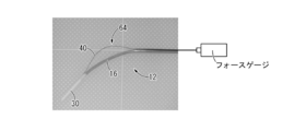
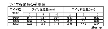
- control wire 40 becomes harder as the diameter increases, and the force required for operation increases. This is because the force required to displace the control wire 40 by a predetermined amount in the feeding direction or the drawing direction of the control wire 40 was measured for the three types of control wires 40 having different cross-sectional diameters by the measuring device shown in FIG. It is clear from the result (see FIG. 17). According to the measurement result shown in FIG. 17, for example, Ni—Ti having a diameter of 0.3 mm can be easily operated by the force of fingers and the catheter body 12 can be bent and deformed efficiently. An alloy control wire 40 is preferably employed.
- the diameter of the control wire 40 is preferably set in a range of 0.2 mm to 0.4 mm, the control wire 40 can be easily operated with fingers, and a sufficient deformation amount of the control wire 40 can be obtained. Can do.
- the force gauge shown in FIG. 16 was measured using a product name: High Performance Digital Force Gauge (product number DPZ-20N) of Imada Co., Ltd.
- the axial force required for the operation of the control wire 40 greatly increases as the amount of control wire 40 increases in a region where the amount of control wire 40 is small.
- the increase amount of the axial force is small with respect to the increase of the feed amount of the control wire 40. This is considered that when the control wire 40 is fed to a certain extent, the control wire 40 protrudes laterally from the open portion 46 and escapes, so that it is difficult for the axial force to increase. It is considered that the amount of bending deformation of 12 is small.
- the axial force that can be effectively transmitted is expected to be smaller as the diameter of the control wire 40 is smaller, the bending deformation of the catheter body 12 can be effectively obtained with respect to the axial force that can be easily exerted by operation with fingers. Therefore, it is necessary to set the wire diameter appropriately.
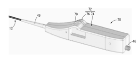
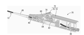
- FIGS. 18 and 19 show a proximal end portion of a catheter 70 as a second embodiment of the present invention.
- the catheter 70 includes a controller 72 at the proximal end portion.
- members and parts that are substantially the same as those in the first embodiment are denoted by the same reference numerals and description thereof is omitted.
- the distal end portion of the catheter 70 has the same structure as the catheter 10 of the first embodiment, illustration and description thereof are omitted here.
- the controller 72 has a structure in which a rotary operation unit 76 that is allowed to rotate is provided for a hollow body 74 held by a practitioner.
- the body 74 of the present embodiment is a curved inclined surface in which the upper surface of the distal end portion is gradually inclined downward toward the distal end, and an operation portion 76 is provided on the proximal end side.
- the operation unit 76 has a substantially disc shape and has an input unit 78 having a non-slip projection on the outer peripheral surface, and a first gear 80 fixedly attached to the input unit 78 on the same central axis. And a second gear 82 that meshes with the first gear 80, and a sliding member 84 that has a rack that meshes with the second gear 82 on its upper surface.
- the upper part of the input part 78 protrudes on the upper surface of the body 74, and the sliding member 84 pulls out with respect to the body 74 with the feeding direction by exerting a rotational force in the circumferential direction on the input part 78 with fingers. It slides in the direction.
- the base end portion of the control wire 40 inserted into the body 74 is fixed to the sliding member 84, and the input member 78 is rotated to slide the sliding member 84. By doing so, the control wire 40 is operated in the feeding direction and the drawing direction.
- the operation unit 76 makes a practitioner perform a predetermined operation by bringing a not-shown claw (plate spring) into contact with at least one of the first and second gears 80 and 82 and the rack of the sliding member 84. A response (click feeling) can be obtained for each rotation operation amount.
- Reinforcing ribs provided inside the body 74 are arranged on both sides of the sliding direction (feeding direction and pulling direction) of the sliding member 84, and the sliding member 84 and the rib are in contact with each other. Therefore, the relative displacement amount of the sliding member 84 with respect to the body 74 is limited. Thereby, the stopper means which restrict
- the input unit 78 is a rotary type, and the amount of operation of the control wire 40 can be controlled by controlling the rotation amount of the input unit 78 provided at a predetermined position with fingers. Can be set. Therefore, even when the operation amount of the control wire 40 is large, it is not necessary to make a design change such as ensuring a large movable stroke of the input unit, and it is possible to cope without requiring an increase in the size of the controller 72 or the like. Therefore, by adopting the controller 72 shown in the present embodiment in combination with the catheter body 12 in which the amount of bending deformation relative to the operation amount of the control wire 40 is set to be small, the bending deformation of the catheter body 12 can be made finer. Can be operated.
- a gear train composed of first and second gears 80 and 82 and a rack of sliding members 84 is provided between the input unit 78 and the control wire 40.
- the catheter body 12 is exemplified by a structure in which the main shaft 16 and the sub shaft 18 that are independent from each other are connected by the cover tube 20.
- the catheter body 12 includes a plurality of lumens including the sublumen 38. You may be comprised with one shaft.
- the shaft has a stepped shape, and the distal end of the sub-lumen 38 is positioned closer to the base end side than the distal end of the other lumen, thereby providing an open portion on the front end side of the sub-lumen 38 and the sub-lumen 38. It is also possible to form an open portion by forming a slit penetrating through the peripheral wall and allowing the control wire 40 to protrude laterally through the slit.
- control wires 40 it is also possible to provide a plurality of control wires 40 so that the catheter body is bent and deformed at a plurality of locations by the axial force exerted on each control wire 40.
- the catheter body may be bent and deformed at a single location by a plurality of control wires 40, for example, two control wires 40, 40 connected to different operation portions 44 are provided,
- the catheter body 12 can be bent and deformed up and down by one control wire 40, and the catheter body 12 can be bent and deformed left and right at the same location by the other control wire 40.
- the operation parts 44 and 76 of the controllers 14 and 72 are operated in steps, and it gives a practitioner a click feeling for every predetermined operation amount.
- a click feeling is not essential.
- a scale may be provided to make it possible to visually confirm the operation amount of the input units 50 and 78.
- the protruding direction of the input parts 50 and 78 from the bodies 42 and 74 does not have to coincide with the protruding direction of the control wire 40 at the opening part 64.
- the input units 50 and 78 may be operable with the thumb of the hand that holds the bodies 42 and 74 projecting from the upper surfaces of the bodies 42 and 74 as shown in the above embodiment. It is not limited, For example, it may protrude by the lower surface front part of the body 42, and it can be operated with the index finger of the hand holding the body 42. FIG.
- the present invention is not only applied to the catheter 10 for thrombus suction, but can be suitably applied to catheters for various treatments (treatments and examinations).
Landscapes
- Health & Medical Sciences (AREA)
- Life Sciences & Earth Sciences (AREA)
- Engineering & Computer Science (AREA)
- Anesthesiology (AREA)
- Biophysics (AREA)
- Pulmonology (AREA)
- Biomedical Technology (AREA)
- Heart & Thoracic Surgery (AREA)
- Hematology (AREA)
- Animal Behavior & Ethology (AREA)
- General Health & Medical Sciences (AREA)
- Public Health (AREA)
- Veterinary Medicine (AREA)
- Mechanical Engineering (AREA)
- Media Introduction/Drainage Providing Device (AREA)
Abstract
先端部分をより高精度に且つ安定して湾曲させて、先端の向きを目的とする方向に容易に制御することが出来る、新規な構造のカテーテルを提供すること。可撓性のカテーテル本体(12)に設けられたコントロールワイヤルーメン(38)に対してコントロールワイヤ(40)を挿通すると共に、コントロールワイヤ(40)の先端部をカテーテル本体(12)の先端部に固定する一方、コントロールワイヤ(40)の側方への突出を許容する開放部(64)をカテーテル本体(12)に設けて、コントロールワイヤ(40)に軸方向力を及ぼすとコントロールワイヤ(40)が開放部(64)から側方に突出してコントロールワイヤ(40)を通じてカテーテル本体(12)の先端部に曲げ力を及ぼすことにより、カテーテル本体(12)の先端側部分が湾曲変形するようになっていると共に、カテーテル本体(12)の基端部には、コントロールワイヤ(40)の送込方向と引出方向の操作量を設定するコントローラ(14)を設けた。
Description
本発明は、血管,消化器管,気管支管などの体内管状組織に挿入して用いられて挿入部位の観察や医療処置を行うカテーテルに関するものである。
従来から、血管や管状器官等の体内管状組織に対して検査や治療等を行うための医療器具の一種として、カテーテルが知られている。具体的には、PCTA(経皮的冠動脈経血管形成術)やPTCR(冠動脈血栓溶解術),PTCD(経皮経肝胆道ドレナージ),PEIT(ペイト)などの処置に際して、カテーテルが用いられている。
ところで、このようなカテーテルを用いた医療処置に際しては、カテーテルを血管等に挿し入れ、カテーテルの先端を体内組織の目的とする部位に至るまで押し進めることが必要となる。その際、血管等は体内で湾曲していることから、カテーテルを血管等の湾曲に沿って挿し入れるために、カテーテル自体を湾曲変形させて先端の向きを変える必要が生じる。また、血管壁内面の血栓などを吸引ルーメンで除去する場合等には、カテーテル本体を湾曲変形させて、カテーテル本体の先端に形成された吸引ルーメンの開口を血管壁内面に向ける必要がある。
そこで、本出願人は、特開2010-213800号公報(特許文献1)において、カテーテル本体の先端部分に突出部を設けて、突出部の血管等に対する当接反力を利用してカテーテル本体の先端部分を湾曲可能としたカテーテルを、提案している。このような特許文献1に記載のカテーテルでは、カテーテル本体の湾曲変形が突出部の血管壁等への当接による反力を利用して積極的に生ぜしめられることにより、カテーテル本体の先端の向きが目的とする方向に変更されて、カテーテル本体の血管等への容易な挿通や、血管壁内面の血栓の効率的な除去などが実現される。
しかしながら、特許文献1のような血管壁内面等への当接による反力を利用して湾曲するカテーテルでは、カテーテルを挿通する血管の形状やカテーテルと血管壁とのクリアランス、血管壁の弾性等に応じて、突出部の突出量に対するカテーテル本体の湾曲変形量が変化し得る。それ故、施術者が突出部の突出量を個々の状況に応じて適宜に調節する必要があって、施術者の負担になることも考えられた。
本発明は、上述の如き事情を背景として為されたものであって、その解決課題とするところは、先端部分をより高精度に且つ安定して湾曲させて、先端の向きを目的とする方向に容易に制御することが出来る、新規な構造のカテーテルを提供することにある。
すなわち、本発明の第1の態様は、体内の管状器官に挿入されるカテーテルであって、可撓性のカテーテル本体に設けられたコントロールワイヤルーメンに対してコントロールワイヤが挿通されていると共に、該コントロールワイヤの先端部が該カテーテル本体の先端部に固定されている一方、該カテーテル本体には該コントロールワイヤの側方への突出を許容する開放部が設けられており、該コントロールワイヤに対して該コントロールワイヤルーメンへの送込方向または引出方向の軸方向力が及ぼされると該コントロールワイヤが該開放部から側方に突出して該コントロールワイヤを通じて該カテーテル本体の先端部に曲げ力が及ぼされることにより、該カテーテル本体の先端側部分が湾曲変形されるようになっていると共に、該カテーテル本体の基端部には、該コントロールワイヤの送込方向と引出方向の操作量を設定するコントローラが設けられていることを、特徴とする。
本発明の第1の態様に従う構造とされたカテーテルによれば、カテーテル本体の開放部においてコントロールワイヤの側方への突出が許容されており、コントロールワイヤに及ぼされる軸方向力が、開放部におけるコントロールワイヤの突出によって、カテーテル本体の先端部に対して曲げ力として作用するようになっている。これにより、コントロールワイヤを送込方向または引出方向に操作することで、カテーテル本体の先端側部分を湾曲変形させることができる。
さらに、本態様に係るカテーテルでは、カテーテル本体の湾曲変形に管状器官への当接等といった外的要因が必要とされないことから、施術者の操作量に応じたカテーテル本体の湾曲変形を安定して発現させることができる。
また、カテーテル本体の基端部分には、コントロールワイヤの送込方向または引出方向の操作量を設定するコントローラが設けられており、施術者がコントロールワイヤの操作量を容易に且つ安定的に設定して、カテーテル本体の湾曲変形を制御することが可能とされている。
本発明の第2の態様は、第1の態様に記載されたカテーテルであって、前記コントロールワイヤの送込方向と引出方向の操作によって、前記カテーテル本体の先端の向きが該カテーテル本体の基端部分の中心軸方向に対して30°以上の角度まで湾曲可能とされているものである。
第2の態様によれば、コントロールワイヤの操作によって、カテーテル本体を実用的に充分に大きく湾曲変形させることが可能であり、管状器官の湾曲に沿って湾曲させたり、カテーテル本体の先端を管状器官の内壁に向けて、血栓の吸引や薬液の塗布等を行ったりすることができる。
本発明の第3の態様は、第1又は第2の態様に記載されたカテーテルであって、前記コントロールワイヤの降伏前の最大曲げ荷重が、前記カテーテル本体の降伏前の最大曲げ荷重に対して10~400%とされているものである。
第3の態様によれば、カテーテル本体とコントロールワイヤの硬さの差が抑えられることによって、カテーテル本体の柔軟な湾曲がコントロールワイヤによって著しく阻害されるのを防ぐことができると共に、コントロールワイヤに軸方向力を及ぼすことにより、カテーテル本体の先端側部分を有効に湾曲変形させることができる。
なお、好適には、前記コントロールワイヤの曲げ剛性が、前記カテーテル本体の曲げ剛性に対して50%以上とされていることが望ましい。これによれば、コントロールワイヤの送込方向または引出方向への操作時に、コントロールワイヤの開放部での突出量に対して、カテーテル本体の湾曲変形が効率的に生ぜしめられる。それ故、コントロールワイヤの操作量に対して、カテーテル本体を効率的に湾曲変形させることができて、施術者のカテーテル操作が容易になる。特に、コントロールワイヤの送込方向への操作時にも、コントロールワイヤの側方への突出量を抑えつつ、カテーテル本体を一層効率的に湾曲変形させることが可能となる。
本発明の第4の態様は、第1~第3の何れか1つの態様に記載されたカテーテルであって、前記カテーテル本体における前記開放部の長さが20mm~40mmとされているものである。
第4の態様によれば、コントロールワイヤの操作量に対するカテーテル本体の先端側部分の傾斜角度や、コントロールワイヤを所定量だけ操作するために必要な力等が、適当に設定され得る。蓋し、開放部の長さが短すぎると、コントロールワイヤの操作量に対してカテーテル本体の先端側部分が大きく傾斜することから、微小なコントロールが困難であると共に、コントロールワイヤの操作に大きな力が必要になる一方、開放部の長さが長すぎると、コントロールワイヤの操作量に対してカテーテル本体の先端側部分の傾斜が小さくなることから、実用的な湾曲変形量を得るためにはコントロールワイヤを大きく操作する必要が生じるからである。
本発明の第5の態様は、第1~第4の何れか1つの態様に記載されたカテーテルであって、前記カテーテル本体の先端から前記開放部までの距離が1mm~30mmとされているものである。
第5の態様によれば、カテーテル本体の湾曲変形に伴う先端の移動距離が実用的に適当な範囲で設定される。蓋し、カテーテル本体は開放部付近で湾曲変形することから、カテーテル本体の先端を同じ向きまで傾斜させた場合に、カテーテル本体の先端の移動距離は、開放部が先端から遠くなるに従って大きくなるからである。なお、血栓吸引用のカテーテル等では、吸引用の開口が潰れるのを防ぐために、カテーテル本体の先端から開放部までの距離が5mm~30mmに設定されることが望ましい。
本発明の第6の態様は、第1~第5の何れか1つの態様に記載されたカテーテルであって、前記コントローラが前記コントロールワイヤの送込方向と引出方向で直線的にスライド変位するスライド式の入力部を備えており、該入力部をスライド操作することで該コントロールワイヤが送込方向と引出方向に操作されるようにしたものである。
第6の態様によれば、施術者による入力部のスライド操作が、コントロールワイヤの送込方向または引出方向の操作と対応することで、施術者はカテーテル本体の湾曲変形をより直感的にコントロールすることが可能となる。
本発明の第7の態様は、第1~第5の何れか1つの態様に記載されたカテーテルにおいて、前記コントローラが回転式の入力部を備えており、該入力部を回転操作することで前記コントロールワイヤが送込方向と引出方向に操作されるようにしたものである。
第7の態様によれば、施術者はコントローラの所定位置に設けられた入力部を回転させることで、コントロールワイヤを容易に操作することができる。更に、入力部の回転量によってコントロールワイヤの操作量が設定されることから、コントロールワイヤの操作量に対するカテーテル本体の湾曲変形量が比較的に小さい場合でも、入力部のストロークの確保等に起因するコントローラの大型化を要することなく、施術者が回転操作量を増すことで対応可能であり、カテーテル本体の湾曲変形をより高精度に制御することができる。
本発明の第8の態様は、第6又は第7の態様に記載されたカテーテルであって、前記入力部が所定量ずつ段階的に操作されるようになっており、該入力部の段階的な操作によって前記コントロールワイヤが所定量ずつ段階的に送込方向と引出方向に操作されるようにしたものである。
第8の態様によれば、施術者は、例えば、所定の操作量毎に感取されるクリック感等によって、入力部の操作量を容易に把握することができる。それ故、カテーテル本体の湾曲変形量のコントロールが一層容易になる。
本発明の第9の態様は、第1~第8の何れか1つの態様に記載されたカテーテルにおいて、前記カテーテル本体がメインルーメンとサブルーメンとを備えており、該サブルーメンによって前記コントロールワイヤルーメンが構成されていると共に、該メインルーメンが該カテーテル本体の先端に開口しているものである。
第9の態様によれば、カテーテル本体がコントロールワイヤルーメンに加えてメインルーメンを備えており、メインルーメンによって、ガイドワイヤの挿通や血栓の吸引、薬液の送入等を実現することができる。しかも、メインルーメンがカテーテル本体の先端に開口していることから、カテーテル本体の湾曲変形によって、メインルーメンの開口方向を管状器官内で変更設定することが可能であり、管状器官の内面に対するメインルーメンを通じた吸引や薬液の塗布等を効率的に実現することもできる。
本発明の第10の態様は、第9の態様に記載されたカテーテルにおいて、前記カテーテル本体の前記メインルーメンが前記コントローラを貫通して基端側に開口していると共に、該メインルーメンの基端開口部にY字コネクタが取り付けられており、該メインルーメンがガイドワイヤルーメンと施術用ルーメンを兼ねているものである。
第10の態様によれば、メインルーメンにY字コネクタを取り付けて、Y字コネクタの一方の基端開口部からガイドワイヤを挿通すると共に、Y字コネクタの他方の基端開口部に薬液の入ったシリンダや吸引ポンプ等を接続することで、メインルーメンをガイドワイヤルーメンおよび施術用ルーメンとして利用することができる。
本発明の第11の態様は、第1~第10の何れか1つの態様に記載されたカテーテルであって、前記コントロールワイヤの先端部が前記コントロールワイヤルーメンから先端側に突出していると共に、該コントロールワイヤの先端部が前記カテーテル本体の先端部に固定されており、該コントロールワイヤルーメンの先端側に前記開放部が設けられているものである。
第11の態様によれば、開放部を備えたカテーテル本体を簡単な構造で実現することができる。また、開放部においてコントロールワイヤがコントロールワイヤルーメンから突出して外部に露出していることから、操作時にコントロールワイヤがコントロールワイヤルーメンの壁部に引っ掛かる等の不具合も回避される。
本発明によれば、コントロールワイヤの側方への突出を許容する開放部がカテーテル本体に設けられており、コントロールワイヤに及ぼされる軸方向力が、カテーテル本体の先端部に曲げ力として及ぼされて、カテーテル本体の先端側部分が湾曲変形されるようになっている。更に、コントロールワイヤの操作量を設定するコントローラが、カテーテル本体の基端部に設けられていることにより、カテーテル本体の先端側部分の湾曲変形をカテーテル本体の基端側でコントロールすることができる。
以下、本発明の実施形態について、図面を参照しつつ説明する。
図1には、本発明の第1の実施形態としてのカテーテル10が示されている。カテーテル10は、先端部分が体内の管状器官に挿入されるカテーテル本体12と、後述するコントロールワイヤ40の操作量を設定するコントローラ14とを、備えている。なお、以下の説明において、カテーテル10の先端とは体内管腔への挿入側である遠位端をいうと共に、カテーテル10の基端とは施術者の操作側である近位端をいう。
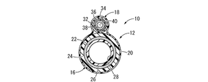
より詳細には、カテーテル本体12は、可撓性を有しており、図2,図3に示されているように、メインシャフト16とサブシャフト18をカバーチューブ20に内挿した構造を有している。メインシャフト16は、それぞれ樹脂製の内層22と外層24の間に、複数の金属線材をメッシュ状に編んだ筒状編組体である補強層26を固着した複層チューブ状とされており、中心孔がメインルーメン28とされて先端および基端に開口している。メインシャフト16の外径寸法および内径寸法や長さ寸法は、適用される管状器官の大きさや治療乃至は検査に必要なルーメン径等に応じて適宜に選択され得るものであるが、例えば、外径寸法が1.35mm~1.75mm、内径寸法が1.3mm~1.5mmとされると共に、長さ寸法が600mm~1500mmとされることが望ましい。また、メインシャフト16の先端部分は、長さ方向で段階的に硬さが変化しており、先端に向かって次第に曲げ強度が小さい柔軟な構造とされて、後述する先端部分の湾曲変形が効率的に生じるようにされている。更に、メインシャフト16の最先端部には、基端部分と同等の硬さを有する先端チップ30が設けられており、管状器官の狭窄部分に対する貫通性が確保されている。なお、メインシャフト16の先端部分において先端チップ30の基端に接続される部分は、内層22と補強層26で構成されており、外層24が省略されることで小径とされている。
サブシャフト18は、メインシャフト16と同様に、樹脂製の内層32と外層34の間に金属製の補強層36を固着したチューブ状であって、メインシャフト16よりも短く且つ小径とされていると共に、中心孔がコントロールワイヤルーメンとしてのサブルーメン38とされている。サブシャフト18の外径寸法および内径寸法も、適用される管状器官の大きさや後述するコントロールワイヤ40の直径等に応じて適宜に選択され得るものであるが、好適には、例えば、外径寸法が0.45mm~0.65mm、内径寸法が0.25mm~0.45mmとされる。なお、メインシャフト16とサブシャフト18は、何れも楕円形断面であっても良い。
なお、メインシャフト16の内層22および外層24と、サブシャフト18の内層32および外層34を形成する樹脂材料は、湾曲可能な軟質材料であれば、何れも特に限定されるものではなく、例えば、ポリアミドやポリ塩化ビニル、ポリウレタン、ポリイミド、ポリエチレン、ポリエチレンエラストマー、ポリプロピレン、ポリテトラフルオロエチレン、ポリエーテルケトン、ポリフッ化ビニリデン等の合成樹脂材料が採用され得る。また、メインシャフト16の補強層26とサブシャフト18の補強層36は、ステンレス鋼やNi-Ti合金等の金属材料で形成され得る。尤も、補強層26,36は、何れも必須ではなく、カテーテル本体12の全体が樹脂で形成されていても良い。その場合には、内層22(32)と外層24(34)が一体形成されていても良いし、互いに異なる樹脂材料で形成された内層と外層とによって構成された積層チューブとされていても良い。
これらメインシャフト16とサブシャフト18は、何れも樹脂製のカバーチューブ20に内挿されており、カバーチューブ20によって互いに並列に延びるように相対的に位置決めされることで、カテーテル本体12が構成されている。なお、カバーチューブ20は、熱収縮等によって、メインシャフト16およびサブシャフト18に密着されていることが望ましい。
また、サブシャフト18のサブルーメン38には、コントロールワイヤ40が挿通されている。コントロールワイヤ40は、Ni-Ti合金等で形成された小径の線状体であって、本実施形態では直径が0.3mmとされている。また、コントロールワイヤ40の降伏前の最大曲げ荷重は、カテーテル本体12の降伏前の最大曲げ荷重に対して、10~400%とされ、より好適には30~200%とされる。更に、コントロールワイヤ40の曲げ剛性は、カテーテル本体12の曲げ剛性に対して、好適には50%以上、より好適には100%以上とされる。これによれば、コントロールワイヤ40に軸方向力を及ぼすことで、カテーテル本体12を効率的に湾曲変形させることができる。なお、コントロールワイヤ40の構造は、特に限定されるものではなく、線材であっても良いが、例えば、複数の線材を縒り合わせる等して形成されていても良い。
また、カテーテル本体12の基端部分には、コントローラ14が取り付けられている。コントローラ14は、図4,図5に示されているように、中空のボデー42に対して相対変位可能な操作部44が設けられた構造を有している。ボデー42は施術者が片手で把持した状態で、後述する操作部44を親指で操作可能な形状および大きさとされている。本実施形態のボデー42は、中空ロッド状とされており、握り易いように、先端部分において下面が先端側に向かって次第に上傾していると共に、基端部分において上面が基端側に向かって次第に下傾している。なお、ボデー42の内部には、板状の補強用リブが設けられており、中空構造とされたボデー42において充分な強度が実現されている。
さらに、ボデー42には、メインシャフト16が挿通されて、メインシャフト16の基端部に取り付けられたルアーコネクタ46がボデー42の基端側に突出しており、メインルーメン28の基端開口部がボデー42の基端側に開口している。なお、ルアーコネクタ46には、Y字コネクタ48が取り付けられて、Y字コネクタ48の一方のルーメンからメインルーメン28にガイドワイヤが挿通されるようになっていると共に、他方のルーメンには血栓吸引用のポンプや薬液を入れたシリンダ等が接続されて、メインルーメン28を通じて血栓等の吸引や薬液の送入を行うことができるようになっている。このことから明らかなように、本実施形態のメインルーメン28は、ガイドワイヤルーメンと施術用ルーメンとを兼ねている。また、カテーテル本体12が挿入されるボデー42の先端部分には、テーパ筒状のストレインリリーフ49が設けられており、カテーテル本体12のボデー42への挿入部分でのキンクが防止されている。
操作部44は、ボデー42に対して、先端側と基端側の両方にそれぞれ所定の距離だけ相対的なスライド変位を許容された状態で取り付けられており、ボデー42の上部に突出する入力部50と、入力部50に固設されてボデー42に収容されたワイヤ保持部52とを備えている。入力部50は、ボデー42から突出して手指でスライド操作できるようになっていれば、その形状等は特に限定されないが、本実施形態では、ボデー42を把持した手の親指で送込方向と引出方向の両方にスライド変位させやすいように、上方に凸の半円板形状とされていると共に、その湾曲した上面には、スライド方向と直交する方向に延びる滑り止めの突起が、放射状に突出して設けられている。
ワイヤ保持部52は、小径筒状の先端固着部54と大径筒状の基端摺動部56とを一体で備えていると共に、コントロールワイヤ40の基端部分が先端固着部54に挿入されて固定されており、入力部50のスライド操作によって、コントロールワイヤ40が送込方向と引出方向に操作されるようになっている。
さらに、基端摺動部56の下面には、所定の領域に亘って凹凸形状を等間隔で繰り返す凹凸部58が設けられており、基端摺動部56がボデー42に対して摺動する際に、凹凸部58の凸部分がボデー42内の補強用リブに設けられた穴部60の開口縁部に当接するようになっている。これにより、入力部50に対する所定の操作量毎に、凹凸部58の凸部分が順次に穴部60の開口縁部に当接して、入力部50が所定量ずつ段階的に操作されるようになっていると共に、ボデー42を把持する施術者が所定の操作量毎にクリック感を感取できるようになっている。
更にまた、操作部44の入力部50は、ボデー42の上面に形成されたスリット62を通じて上方に突出していることから、スリット62内面への当接によってスライド変位量が制限されており、もって送込方向と引出方向で許容されるコントロールワイヤ40の操作量を制限するストッパ手段が構成されている。
そして、操作部44の入力部50に手指で外力を及ぼして、操作部44を先端側と基端側にスライド変位させることにより、コントロールワイヤ40に対して送込方向または引出方向の軸方向力が及ぼされる。このように、入力部50に対する入力操作によって、コントロールワイヤ40が送込方向と引出方向に操作されるようになっており、コントローラ14によってコントロールワイヤ40の操作量が設定されるようになっている。なお、操作部44の操作方法は、特に限定されるものではないが、例えばボデー42を把持した手の親指で入力部50に外力を及ぼすことで、カテーテル10の操作を行いながら、操作部44を操作することができる。
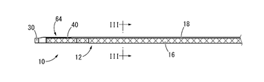
操作部44に基端部を固定されたコントロールワイヤ40は、図6に示されているように、先端部分がサブシャフト18のサブルーメン38の先端から突出していると共に、最先端部がメインシャフト16の先端部に固定されている。これにより、メインシャフト16の先端部とサブシャフト18の先端との間に開放部64が形成されており、開放部64においてコントロールワイヤ40がカテーテル本体12の周上で部分的に外部に露出して側方への突出を許容されている。
このような開放部64が設けられていることにより、入力部50を操作してコントロールワイヤ40をサブルーメン38に対して送込方向または引出方向に変位させると、コントロールワイヤ40が開放部64を通じてカテーテル本体12の側方(図2中の上方)に突出して、カテーテル本体12がコントロールワイヤ40に作用する軸方向力によって湾曲変形されるようになっている。即ち、図6(b)には、コントロールワイヤ40を送込方向に操作した状態が示されている。コントロールワイヤ40を送込方向に操作すると、先端をメインシャフト16によって支持されたコントロールワイヤ40は、開放部64を通じて上方に向かって凸となるように湾曲変形して、カテーテル本体12から離隔して上方に突出する。これにより、操作部44の操作によってコントロールワイヤ40に及ぼされる先端側への軸方向力が、カテーテル本体12の先端部に対して下方への押圧力(曲げ力)としても作用して、カテーテル本体12の先端側部分は先端が下を向くように湾曲変形するようになっている。
一方、操作部44の操作によってコントロールワイヤ40を引出方向に操作すると、コントロールワイヤ40の先端に固定されたメインシャフト16の先端部分が、コントロールワイヤ40の軸方向力で基端側に引き込まれる。コントロールワイヤ40は、メインシャフト16の弾性中心を外れた上面に固着されていることから、コントロールワイヤ40の軸方向力によってメインシャフト16が先端に向かって上傾するように湾曲変形する。更に、メインシャフト16の湾曲変形状態において、コントロールワイヤ40のメインシャフト16に沿った湾曲が、開放部64からの突出によって抑えられて、先端部分においてコントロールワイヤ40とメインシャフト16の先端部分との相対的な傾斜角度が確保される。それ故、コントロールワイヤ40の軸方向力が、メインシャフト16に対して曲げ力として効率的に作用するようになっている。
このように、カテーテル10では、コントロールワイヤ40に対する軸方向力の作用時に、コントロールワイヤ40が開放部64においてメインシャフト16から側方に突出して、コントロールワイヤ40の先端部分の中心軸:lが、メインシャフト16の先端部分の中心軸:mに対して、所定の傾斜角度:αで相対的に傾斜するようになっている。これにより、コントロールワイヤ40に及ぼされる軸方向力が、メインシャフト16の先端部分に対して、中心軸方向から角度:αだけ傾斜した方向に及ぼされる。その結果、コントロールワイヤ40の軸方向力に対する支持反力が、メインシャフト16に対して曲げ方向に作用して、メインシャフト16がコントロールワイヤ40の軸方向力によって湾曲変形されるようになっている。従って、入力部50をスライド変位させるだけの極めて容易な操作によって、メインシャフト16の先端の向きを変更することができる。
これにより、カテーテル本体12の先端に開口するメインルーメン28の先端側開口部の向きを変更させることができて、例えば、血管等の管状器官の壁内面に向けることで、血栓を吸引除去したり、薬液を塗布したりすることができる。また、メインルーメン28は、Y字コネクタ48によって、上述の如き治療や検査を実施するための施術用ルーメンとしての機能に加えて、ガイドワイヤを挿通するガイドワイヤルーメンとしても機能するようになっており、ガイドワイヤに沿ってカテーテル本体12の先端部分を治療部位まで押し進めた後、ガイドワイヤを抜去したカテーテル本体12の先端部を湾曲変形させることで、治療部位に対する治療を行うことができる。
図6(b)では、血管等の管状器官の内面が2点鎖線で図示されている。この図にも示されているように、カテーテル本体12の湾曲変形は、カテーテル本体12やコントロールワイヤ40の管状器官内面への当接を必要とすることなく、コントロールワイヤ40の軸方向力によって生ぜしめられるようになっている。これにより、手指による操作部44の操作量に応じたカテーテル本体12の湾曲変形を、管状器官の形状や大きさ、弾性等に影響されることなく、高精度に生ぜしめることができる。なお、図6(b)では、分かり易さのために、コントロールワイヤ40を大きく押し込んで、カテーテル本体12の先端側部分を大きく湾曲変形させた状態が示されており、それに伴って仮想的に示された管状器官の内面の直径(図6(b)中における2点鎖線の間隔)がカテーテル10に対して大きく示されている。
また、コントロールワイヤ40の基端部分は、カテーテル本体12の基端部に設けられたコントローラ14によって、送込方向または引出方向の操作量が設定されるようになっており、施術者はコントローラ14の入力部50を手動で操作することによって、カテーテル本体12を容易に湾曲変形させることができる。
特に本実施形態のコントローラ14では、入力部50が直線的に移動するスライド式とされており、施術者はコントロールワイヤ40の操作をより直感的に行うことができる。しかも、入力部50は、凹凸部58が穴部60の開口部上を移動することによって、所定の操作量ずつ段階的にスライド操作されるようになっている。このような入力部50の段階的な操作によって、カテーテル本体12の湾曲変形を所定量ずつ段階的に生ぜしめることができて、カテーテル本体12の湾曲変形量を調節し易くなっている。加えて、凹凸部58が穴部60の開口部上を移動することによる手応え(クリック感)によって、施術者が操作量を容易に把握することも可能とされている。
好適には、操作部44の操作によって、カテーテル本体12の先端の向きがカテーテル本体12の基端部分に対して30°以上の角度となるまで、カテーテル本体12の湾曲変形が許容される。換言すれば、カテーテル本体12の先端部分の中心軸:mと、カテーテル本体12の基端部分の中心軸:nとの成す角:βが30°以上の角度となるまで、カテーテル本体12を湾曲変形させることが可能とされる。これにより、カテーテル本体12において充分に実用的な湾曲変形が実現されて、管状器官の治療や検査を有効に行うことができる。なお、図6(b)では、カテーテル本体12の先端部分の中心軸:mと基端部分の中心軸:nが、それぞれ1点鎖線で示されている。
さらに、カテーテル本体12の湾曲変形状態において、コントロールワイヤ40の上方への最大突出量:Aよりも、カテーテル本体12の先端の下方への突出量:Bが大きくなっている。このように、カテーテル本体12は、コントロールワイヤ40の開放部64を通じた突出量に対して効率的に湾曲変形することが望ましく、カテーテル本体12を管状器官内の限られた空間で有効に湾曲変形させることができる。
また、図6(a)に示された開放部64の長さ:Lは、好適には20mm~40mmとされ、より好適には30mm前後に設定される。更に、操作部44のスライド変位の許容量、換言すれば、コントロールワイヤ40の送込方向と引出方向の最大変位量は、各3mm以下であることが望ましく、これによって、開放部64におけるコントロールワイヤ40の上方への突出量が過大になるのが防止されると共に、カテーテル本体12の先端の下方への変位量も適当に設定されて、血管内等の限られたスペースにおいてもカテーテル本体12の湾曲変形が有効に生ぜしめられる。
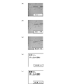
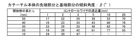
これらの数値範囲は、図7~図11に示すように、実際の測定によっても確認した。即ち、図7が開放部64の長さ:L=50mm、図8がL=40mm、図9がL=30mm、図10がL=20mm、図11がL=10mmの場合であって、各図における(a)がコントロールワイヤ40の送込方向への操作量(送込量)が0mm、(b)がコントロールワイヤ40の送込量が1mm、(c)がコントロールワイヤ40の送込量が3mm、(d)がコントロールワイヤ40の送込量が5mm、(e)がコントロールワイヤ40の送込量が10mmの場合を、それぞれ示す。これらの実測により、コントロールワイヤ40の送込量の調節によって、メインルーメン28の先端開口方向やカテーテル本体12の湾曲変形の程度を制御できることを、確認した。また、開放部64の長さ:Lの違いが、コントロールワイヤ40の上方への最大突出量:Aや、カテーテル本体12の先端の下方への突出量:Bには、あまり影響せず、更に、開放部64の長さ:Lが大きくなるに従って、カテーテル本体12の湾曲部分の長さ寸法が大きくなると共に、カテーテル本体12における先端部分の基端部分に対する傾斜角度:βが小さくなる傾向にあることも、確認した。そして、実際の血管等の管状器官の形状や大きさ等を考慮すると、それら実測データから、好適な開放部64の長さ:Lの範囲が20mm≦L≦40mmであることと、好適なコントロールワイヤ40の最大変位量が3mm以下であることを、確認した。
また、図12の表には、開放部64の長さ:Lに対するカテーテル本体12の先端の下方への突出量:Bの実測値が示されている。これによれば、長さ:Lの違いが突出量:Bに及ぼす影響は小さいことを、確認した。
さらに、図13の表には、開放部64の長さ:Lと、カテーテル本体12における先端部分の基端部分に対する傾斜角度:βとの関係が示されている。これによれば、原則として長さ:Lが小さいほど傾斜角度:βが大きくなることを、確認した。
さらに、カテーテル本体12の先端から開放部64までの距離:Dは、1mm~30mmの間に設定されることが望ましい。蓋し、カテーテル本体12の先端から開放部64までの距離が遠いと、湾曲変形したカテーテル本体12において先端の下方への突出量:Bが大きくなり過ぎるおそれがある一方、開放部64までの距離が近いと、カテーテル本体12の先端の下方への突出量:Bが不充分になったり、コントロールワイヤ40のメインシャフト16への固定部分の長さが充分に確保できないなどの不具合が生じ得るからである。なお、例えば先端チップ30にメインルーメン28の先端側開口部が形成された血栓吸引用のカテーテル等では、5mm~30mmの間に設定されることが望ましく、コントロールワイヤ40の操作時に、メインシャフト16の変形によってメインルーメン28の先端側開口部が潰れるのを防ぐことができる。
また、コントロールワイヤ40の直径や材質は特に限定されないが、コントロールワイヤ40の降伏前の最大曲げ荷重が、カテーテル本体12の降伏前の最大曲げ荷重に対して10~400%とされていることが望ましく、より好適には30~200%とされる。これによれば、コントロールワイヤ40に軸方向力を及ぼしてカテーテル本体12の先端部分を湾曲変形させる際に、カテーテル本体12とコントロールワイヤ40の何れかが塑性変形することなく、両方を弾性変形させることができる。それ故、カテーテル本体12の湾曲変形と形状復元を、安定して繰り返し発現させることができる。
さらに、コントロールワイヤ40の剛性がカテーテル本体12の柔軟性に及ぼす悪影響が抑えられると共に、コントロールワイヤ40の操作によってカテーテル本体12を有効に湾曲変形させることができる。しかも、曲げ荷重に対するカテーテル本体12とコントロールワイヤ40の曲げ変形量の差が小さくされて、コントロールワイヤ40を操作する施術者が操作量や操作の手応えなどから想定する湾曲変形量に対して、カテーテル本体12の湾曲変形量が近くなることから、カテーテル10を容易に且つ高精度に操作することができる。
なお、コントロールワイヤ40およびカテーテル本体12の降伏前の最大曲げ荷重は、例えば、図14に示すような3点曲げ試験によって測定され得る。図15には、カテーテル本体12の降伏前最大曲げ荷重と、直径が0.20mm,0.30mm,0.40mmとされたコントロールワイヤ40で、それぞれステンレス(SUS)で形成した場合と、Ni-Ti合金で形成した場合とについての各降伏前最大曲げ荷重とを、3点曲げ試験で測定した結果が示されている。このように、20~40mmのコントロールワイヤ40の降伏前の最大曲げ荷重は、ステンレス製とNi-Ti合金製の何れにおいても、カテーテル本体12の降伏前の最大曲げ荷重に対して、10~400%の範囲に設定されている。特に、0.20mmのステンレス製と、0.30mmのステンレス製およびNi-Ti合金製と、0.40mmのNi-Ti合金製のコントロールワイヤ40では、降伏前の最大曲げ荷重がカテーテル本体12の30~200%とされて、より好適である。
さらに、コントロールワイヤ40は、直径が大きくなるに従って硬くなり、操作に必要な力が大きくなる。このことは、図16に示された測定装置によって、コントロールワイヤ40の送込方向または引出方向に所定量だけ変位させるために必要な力を、断面径の異なる3種類のコントロールワイヤ40について測定した結果(図17参照)からも明らかである。図17に示された測定結果によれば、手指の力で簡単に操作可能であり、且つカテーテル本体12を効率的に湾曲変形させることができるように、例えば、直径0.3mmのNi-Ti合金製コントロールワイヤ40が好適に採用される。また、コントロールワイヤ40の直径は、0.2mm~0.4mmの範囲に設定されることが望ましく、コントロールワイヤ40を手指で容易に操作可能で、且つコントロールワイヤ40の変形量を充分に得ることができる。なお、図17の測定結果を得るにあたって、図16に図示するフォースゲージとしては、株式会社イマダ社の商品名:高性能デジタルフォースゲージ(品番DPZ-20N)を用いて測定した。
更にまた、図17の測定結果からも読み取れるように、コントロールワイヤ40の操作に必要な軸力は、コントロールワイヤ40の送込量が小さい領域では、コントロールワイヤ40の送込量が増すに従って大きく増す一方、コントロールワイヤ40の送込量が大きい領域では、コントロールワイヤ40の送込量の増加に対して軸力の増加幅が小さくなる。これは、コントロールワイヤ40をある程度以上送り込むと、コントロールワイヤ40が開放部46から側方に突出して逃げることから、軸力が増大し難くなるものと考えられ、コントロールワイヤ40の送込みに対するカテーテル本体12の湾曲変形量が小さくなっているものと考えられる。コントロールワイヤ40の直径が小さいほど有効に伝達し得る軸力が小さくなることが予想されることから、手指による操作で容易に及ぼし得る軸力に対して、カテーテル本体12の湾曲変形が有効に得られるように、ワイヤ径を適切に設定することが必要になる。
図18,図19には、本発明の第2の実施形態としてのカテーテル70の基端部分が示されている。このカテーテル70は、基端部分にコントローラ72を備えている。なお、以下の説明において、第1の実施形態と実質的に同一の部材および部位については、同一の符号を付すことで説明を省略する。また、カテーテル70の先端部分は、第1の実施形態のカテーテル10と同じ構造であることから、ここでは図示および説明を省略する。
コントローラ72は、施術者によって把持される中空のボデー74に対して、回転作動を許容された回転式の操作部76を設けた構造とされている。本実施形態のボデー74は、先端部分の上面が先端に向かって次第に下傾する湾曲傾斜面とされており、その基端側に操作部76が設けられている。
操作部76は、略円板形状で外周面に滑り止めの突起を備えた入力部78と、入力部78に対して同一中心軸上で重ね合わされた状態に固設された第1の歯車80と、第1の歯車80に噛合する第2の歯車82と、第2の歯車82に噛合するラックを上面に備えた摺動部材84とを、含んで構成されている。
そして、入力部78の上部がボデー74の上面に突出しており、入力部78に対して手指で周方向の回転力を及ぼすことにより、摺動部材84がボデー74に対して送込方向と引出方向に摺動するようになっている。図中では必ずしも明らかでないが、この摺動部材84には、ボデー74に挿入されたコントロールワイヤ40の基端部分が固定されており、入力部78を回転操作して摺動部材84をスライド変位させることにより、コントロールワイヤ40が送込方向と引出方向に操作されるようになっている。なお、操作部76は、第1,第2の歯車80,82と摺動部材84のラックとの少なくとも1つに、図示しない爪(板ばね)を当接させることで、施術者は所定の回転操作量毎に手応え(クリック感)を得ることができる。
なお、摺動部材84の摺動方向(送込方向と引出方向)の両側には、ボデー74の内部に設けられた補強用のリブが配置されており、摺動部材84とリブの当接によって、摺動部材84のボデー74に対する相対変位量が制限されている。これにより、コントロールワイヤ40のサブルーメン38に対する送込量と引出量を制限するストッパ手段が構成されている。
このようなコントローラ72を備えたカテーテル70では、入力部78が回転式とされており、所定位置に設けられた入力部78の回転量を手指でコントロールすることにより、コントロールワイヤ40の操作量を設定することができる。それ故、コントロールワイヤ40の操作量が大きい場合にも、入力部の可動ストロークを大きく確保する等の設計変更が不要であり、コントローラ72の大型化等を要することなく対応することができる。従って、コントロールワイヤ40の操作量に対する湾曲変形量を小さく設定されたカテーテル本体12に対して、本実施形態に示されたコントローラ72を組み合わせて採用することで、カテーテル本体12の湾曲変形をより微細に操作することができる。
さらに、入力部78とコントロールワイヤ40の間には、第1,第2の歯車80,82と摺動部材84のラックとで構成された歯車列が設けられている。かかる歯車列のギヤ比を調節すれば、入力部78の回転操作量に対するコントロールワイヤ40の操作量(コントロールワイヤ40に及ぼされる軸方向力の大きさ)を調節することができる。
以上、本発明の実施形態について詳述してきたが、本発明はその具体的な記載によって限定されない。例えば、前記実施形態では、カテーテル本体12として、互いに独立したメインシャフト16とサブシャフト18をカバーチューブ20で連結した構造が例示されているが、例えば、サブルーメン38を含む複数のルーメンを備えた1つのシャフトで構成されていても良い。その場合には、シャフトを段付き形状として、サブルーメン38の先端を他のルーメンの先端よりも基端側に位置させることで、サブルーメン38の先端側に開放部を設ける他、サブルーメン38の周壁を貫通するスリットを形成して、そのスリットを通じてコントロールワイヤ40の側方への突出を許容することで開放部とすることもできる。
また、複数のコントロールワイヤ40を設けて、各コントロールワイヤ40に及ぼされる軸方向力によって、カテーテル本体が複数箇所で湾曲変形されるようにもできる。更に、複数のコントロールワイヤ40によってカテーテル本体が一箇所で湾曲変形されるようになっていても良く、例えば、互いに異なる操作部44に接続された2つのコントロールワイヤ40,40が設けられており、一方のコントロールワイヤ40によってカテーテル本体12が上下に湾曲変形されると共に、他方のコントロールワイヤ40によってカテーテル本体12が同じ箇所で左右に湾曲変形されるようにもできる。
また、前記実施形態では、コントローラ14,72の操作部44,76が段階的に操作されるようになっており、所定の操作量毎に施術者にクリック感を与えるようにされているが、このようなクリック感は必須ではない。更に、クリック感に代えて或いは加えて、入力部50,78の操作量を目視で確認可能とするために目盛を設ける等しても良い。
また、入力部50,78のボデー42,74からの突出方向は、開放部64におけるコントロールワイヤ40の突出方向と一致している必要はない。
また、入力部50,78は、前記実施形態に示されているようにボデー42,74の上面に突出して、ボデー42,74を把持する手の親指で操作可能とされていても良いが、限定されるものではなく、例えば、ボデー42の下面前部に突出して、ボデー42を把持する手の人差し指で操作可能とされていても良い。
また、本発明は、血栓吸引用のカテーテル10にのみ適用されるものではなく、各種の施術(治療や検査)用のカテーテルに好適に適用され得る。
10,70:カテーテル、12:カテーテル本体、14,72:コントローラ、28:メインルーメン、38:サブルーメン(コントロールワイヤルーメン)、40:コントロールワイヤ、48:Y字コネクタ、50,78:入力部、64:開放部
Claims (11)
- 体内の管状器官に挿入されるカテーテルであって、
可撓性のカテーテル本体に設けられたコントロールワイヤルーメンに対してコントロールワイヤが挿通されていると共に、該コントロールワイヤの先端部が該カテーテル本体の先端部に固定されている一方、該カテーテル本体には該コントロールワイヤの側方への突出を許容する開放部が設けられており、
該コントロールワイヤに対して該コントロールワイヤルーメンへの送込方向または引出方向の軸方向力が及ぼされると該コントロールワイヤが該開放部から側方に突出して該コントロールワイヤを通じて該カテーテル本体の先端部に曲げ力が及ぼされることにより、該カテーテル本体の先端側部分が湾曲変形されるようになっていると共に、
該カテーテル本体の基端部には、該コントロールワイヤの送込方向と引出方向の操作量を設定するコントローラが設けられていることを特徴とするカテーテル。 - 前記コントロールワイヤの送込方向または引出方向の操作によって、前記カテーテル本体の先端の向きが該カテーテル本体の基端部分の中心軸方向に対して30°以上の角度まで湾曲可能とされている請求項1に記載のカテーテル。
- 前記コントロールワイヤの降伏前の最大曲げ荷重が、前記カテーテル本体の降伏前の最大曲げ荷重に対して10~400%とされている請求項1又は2に記載のカテーテル。
- 前記カテーテル本体における前記開放部の長さが20mm~40mmとされている請求項1~3の何れか1項に記載のカテーテル。
- 前記カテーテル本体の先端から前記開放部までの距離が1mm~30mmとされている請求項1~4の何れか1項に記載のカテーテル。
- 前記コントローラが前記コントロールワイヤの送込方向と引出方向で直線的にスライド変位するスライド式の入力部を備えており、該入力部をスライド操作することで該コントロールワイヤが送込方向と引出方向に操作されるようにした請求項1~5の何れか1項に記載のカテーテル。
- 前記コントローラが回転式の入力部を備えており、該入力部を回転操作することで前記コントロールワイヤが送込方向と引出方向に操作されるようにした請求項1~5の何れか1項に記載のカテーテル。
- 前記入力部が所定量ずつ段階的に操作されるようになっており、該入力部の段階的な操作によって前記コントロールワイヤが所定量ずつ段階的に送込方向と引出方向に操作されるようにした請求項6又は7に記載のカテーテル。
- 前記カテーテル本体がメインルーメンとサブルーメンとを備えており、該サブルーメンによって前記コントロールワイヤルーメンが構成されていると共に、該メインルーメンが該カテーテル本体の先端に開口している請求項1~8の何れか1項に記載のカテーテル。
- 前記カテーテル本体の前記メインルーメンが前記コントローラを貫通して基端側に開口していると共に、該メインルーメンの基端開口部にY字コネクタが取り付けられており、該メインルーメンがガイドワイヤルーメンと施術用ルーメンを兼ねている請求項9に記載のカテーテル。
- 前記コントロールワイヤの先端部が前記コントロールワイヤルーメンから先端側に突出していると共に、該コントロールワイヤの先端部が前記カテーテル本体の先端部に固定されており、該コントロールワイヤルーメンの先端側に前記開放部が設けられている請求項1~10の何れか1項に記載のカテーテル。
Priority Applications (1)
| Application Number | Priority Date | Filing Date | Title |
|---|---|---|---|
| JP2017511486A JPWO2016163155A1 (ja) | 2015-04-10 | 2016-02-15 | カテーテル |
Applications Claiming Priority (2)
| Application Number | Priority Date | Filing Date | Title |
|---|---|---|---|
| JP2015-080507 | 2015-04-10 | ||
| JP2015080507 | 2015-04-10 |
Publications (1)
| Publication Number | Publication Date |
|---|---|
| WO2016163155A1 true WO2016163155A1 (ja) | 2016-10-13 |
Family
ID=57072638
Family Applications (1)
| Application Number | Title | Priority Date | Filing Date |
|---|---|---|---|
| PCT/JP2016/054334 Ceased WO2016163155A1 (ja) | 2015-04-10 | 2016-02-15 | カテーテル |
Country Status (2)
| Country | Link |
|---|---|
| JP (1) | JPWO2016163155A1 (ja) |
| WO (1) | WO2016163155A1 (ja) |
Citations (5)
| Publication number | Priority date | Publication date | Assignee | Title |
|---|---|---|---|---|
| JPH08510666A (ja) * | 1993-05-28 | 1996-11-12 | メドトロニック・インコーポレーテッド | 操縦可能なスタイレットと操作可能なハンドルとのアッセンブリ |
| JP2000516110A (ja) * | 1996-04-08 | 2000-12-05 | カーディマ・インコーポレイテッド | 線状の切除デバイス及びアセンブリー |
| WO2001089624A1 (en) * | 2000-05-19 | 2001-11-29 | C.R. Bard, Inc. | Steerable biliary catheter |
| JP2002248173A (ja) * | 2001-02-27 | 2002-09-03 | Asahi Optical Co Ltd | 内視鏡用チューブ状処置具 |
| JP2010213800A (ja) * | 2009-03-13 | 2010-09-30 | Nipro Corp | カテーテル |
-
2016
- 2016-02-15 JP JP2017511486A patent/JPWO2016163155A1/ja active Pending
- 2016-02-15 WO PCT/JP2016/054334 patent/WO2016163155A1/ja not_active Ceased
Patent Citations (5)
| Publication number | Priority date | Publication date | Assignee | Title |
|---|---|---|---|---|
| JPH08510666A (ja) * | 1993-05-28 | 1996-11-12 | メドトロニック・インコーポレーテッド | 操縦可能なスタイレットと操作可能なハンドルとのアッセンブリ |
| JP2000516110A (ja) * | 1996-04-08 | 2000-12-05 | カーディマ・インコーポレイテッド | 線状の切除デバイス及びアセンブリー |
| WO2001089624A1 (en) * | 2000-05-19 | 2001-11-29 | C.R. Bard, Inc. | Steerable biliary catheter |
| JP2002248173A (ja) * | 2001-02-27 | 2002-09-03 | Asahi Optical Co Ltd | 内視鏡用チューブ状処置具 |
| JP2010213800A (ja) * | 2009-03-13 | 2010-09-30 | Nipro Corp | カテーテル |
Also Published As
| Publication number | Publication date |
|---|---|
| JPWO2016163155A1 (ja) | 2018-03-15 |
Similar Documents
| Publication | Publication Date | Title |
|---|---|---|
| CN111315435B (zh) | 可转向装置和系统 | |
| US10279150B2 (en) | Guidewire | |
| JP5317566B2 (ja) | カテーテル組立体 | |
| JP6705812B2 (ja) | 介入処置を実行するための介入装置 | |
| JP7115686B2 (ja) | カテーテル | |
| CN105722546A (zh) | 具有可移动末梢的医疗器械 | |
| WO2007131107A1 (en) | Deflectable sheath handle assembly | |
| US10799686B2 (en) | Guidewire torquer | |
| WO2007134341A2 (en) | Steerable sheath actuator | |
| JP2007301360A (ja) | 処置具挿脱用補助装置 | |
| US20230181011A1 (en) | Medical systems, devices, and related methods | |
| US20130018307A1 (en) | Multi-Lumen Steerable Catheter | |
| JP2015130898A (ja) | 操作部材 | |
| WO2018062155A1 (ja) | ガイドワイヤ | |
| WO2016163155A1 (ja) | カテーテル | |
| JP3179894U (ja) | カテーテル | |
| JP6633513B2 (ja) | カテーテル及びカテーテルセット | |
| US20240325687A1 (en) | Force-limiting access system and method of use | |
| JP7324898B2 (ja) | 医療器具および医療器具セット | |
| US20260027331A1 (en) | Endovascular device | |
| EP3235536B1 (en) | Guidewire torquer | |
| JP6754271B2 (ja) | カテーテル組立体 |
Legal Events
| Date | Code | Title | Description |
|---|---|---|---|
| 121 | Ep: the epo has been informed by wipo that ep was designated in this application |
Ref document number: 16776324 Country of ref document: EP Kind code of ref document: A1 |
|
| ENP | Entry into the national phase |
Ref document number: 2017511486 Country of ref document: JP Kind code of ref document: A |
|
| NENP | Non-entry into the national phase |
Ref country code: DE |
|
| 122 | Ep: pct application non-entry in european phase |
Ref document number: 16776324 Country of ref document: EP Kind code of ref document: A1 |