WO2016163144A1 - 工具装着方法、及び、チェーン式工具マガジン - Google Patents
工具装着方法、及び、チェーン式工具マガジン Download PDFInfo
- Publication number
- WO2016163144A1 WO2016163144A1 PCT/JP2016/053514 JP2016053514W WO2016163144A1 WO 2016163144 A1 WO2016163144 A1 WO 2016163144A1 JP 2016053514 W JP2016053514 W JP 2016053514W WO 2016163144 A1 WO2016163144 A1 WO 2016163144A1
- Authority
- WO
- WIPO (PCT)
- Prior art keywords
- tool
- pot
- hollow shaft
- chain
- hollow
- Prior art date
- Legal status (The legal status is an assumption and is not a legal conclusion. Google has not performed a legal analysis and makes no representation as to the accuracy of the status listed.)
- Ceased
Links
Images

Classifications
-
- B—PERFORMING OPERATIONS; TRANSPORTING
- B23—MACHINE TOOLS; METAL-WORKING NOT OTHERWISE PROVIDED FOR
- B23Q—DETAILS, COMPONENTS, OR ACCESSORIES FOR MACHINE TOOLS, e.g. ARRANGEMENTS FOR COPYING OR CONTROLLING; MACHINE TOOLS IN GENERAL CHARACTERISED BY THE CONSTRUCTION OF PARTICULAR DETAILS OR COMPONENTS; COMBINATIONS OR ASSOCIATIONS OF METAL-WORKING MACHINES, NOT DIRECTED TO A PARTICULAR RESULT
- B23Q3/00—Devices holding, supporting, or positioning work or tools, of a kind normally removable from the machine
- B23Q3/155—Arrangements for automatic insertion or removal of tools, e.g. combined with manual handling
-
- B—PERFORMING OPERATIONS; TRANSPORTING
- B23—MACHINE TOOLS; METAL-WORKING NOT OTHERWISE PROVIDED FOR
- B23Q—DETAILS, COMPONENTS, OR ACCESSORIES FOR MACHINE TOOLS, e.g. ARRANGEMENTS FOR COPYING OR CONTROLLING; MACHINE TOOLS IN GENERAL CHARACTERISED BY THE CONSTRUCTION OF PARTICULAR DETAILS OR COMPONENTS; COMBINATIONS OR ASSOCIATIONS OF METAL-WORKING MACHINES, NOT DIRECTED TO A PARTICULAR RESULT
- B23Q3/00—Devices holding, supporting, or positioning work or tools, of a kind normally removable from the machine
- B23Q3/155—Arrangements for automatic insertion or removal of tools, e.g. combined with manual handling
- B23Q3/157—Arrangements for automatic insertion or removal of tools, e.g. combined with manual handling of rotary tools
- B23Q3/15713—Arrangements for automatic insertion or removal of tools, e.g. combined with manual handling of rotary tools a transfer device taking a single tool from a storage device and inserting it in a spindle
- B23Q3/1572—Arrangements for automatic insertion or removal of tools, e.g. combined with manual handling of rotary tools a transfer device taking a single tool from a storage device and inserting it in a spindle the storage device comprising rotating or circulating storing means
- B23Q3/15724—Chains or belts
-
- B—PERFORMING OPERATIONS; TRANSPORTING
- B23—MACHINE TOOLS; METAL-WORKING NOT OTHERWISE PROVIDED FOR
- B23Q—DETAILS, COMPONENTS, OR ACCESSORIES FOR MACHINE TOOLS, e.g. ARRANGEMENTS FOR COPYING OR CONTROLLING; MACHINE TOOLS IN GENERAL CHARACTERISED BY THE CONSTRUCTION OF PARTICULAR DETAILS OR COMPONENTS; COMBINATIONS OR ASSOCIATIONS OF METAL-WORKING MACHINES, NOT DIRECTED TO A PARTICULAR RESULT
- B23Q3/00—Devices holding, supporting, or positioning work or tools, of a kind normally removable from the machine
- B23Q3/155—Arrangements for automatic insertion or removal of tools, e.g. combined with manual handling
- B23Q3/157—Arrangements for automatic insertion or removal of tools, e.g. combined with manual handling of rotary tools
Definitions
- the present invention provides, for example, a tool mounting method for mounting a tool on a spindle [main
- a machine tool such as a machining center (tool mounting [portion] [portion])
- a plurality of tools removably supported
- chain-type tool magazine chain-type tool magazine
- the tool is changed by an automatic tool changer [ATC] (ATC) provided between a tool magazine having a plurality of tools that can be freely attached and detached and a spindle (tool mounting part) of the machine tool. It is automatically exchanged.
- ATC automatic tool changer
- Patent Documents 1 and 2 below disclose a chain-type tool magazine (separable-type tool pod chain) that detachably supports many tools.
- Patent Document 1 discloses a tool magazine provided with a tool pot separation type chain.
- This tool pot separation type chain is provided with an opening portion that is opened outward in the chain travel plane, which is orthogonal to the transfer direction of the chain, in each link plate.
- a tool pot can be attached to and detached from the outside from the outside (see FIG. 2 of Patent Document 1).
- the tool pot separation type chain has a large width because it includes the chain and the opening portion opened to the side.
- a guide member that bends in order to bend the chain the configuration of the tool magazine is complicated (see guide members 12 to 15 shown in FIG. 3 of Patent Document 1).
- Patent Document 2 described above discloses a tool pot separation type chain.
- This tool pot separation type chain is guided by a guide rail and a pot regulation rail provided in parallel.
- maintained at the chain is attached or detached to the side. Therefore, the configuration of the tool magazine is complicated as in the case of the tool magazine disclosed in Patent Document 1 described above (see the rails 16 and 17 shown in FIG. 1 of Patent Document 2).
- the said patent document 1 is also disclosing the structure by which a tool pot is supported in the hollow link which pivotally connects the link plate of a chain (refer FIG.6 and FIG.7 of the said patent document 1:
- This structure is " It is not a “tool pot separation type”).
- the above-described guide member is unnecessary, and the configuration of the tool magazine can be simplified and the space can be saved.
- a locking member such as a ball plunger provided in the tool pot, Since the tool pod cannot be separated from the chain, it is difficult to remove the tool.
- an object of the present invention is to provide a tool mounting method and a chain type tool magazine capable of easily exchanging tools when exchanging tools using an automatic tool changer (ATC) or the like.
- Another object of the present invention is to provide a chain type tool magazine capable of simplifying the configuration.
- a first feature of the present invention is a method for mounting a tool on a tool mounting portion in a machine tool, the axial direction relative to a hollow portion of a hollow shaft that pivotally connects an inner link plate and an outer link plate in an endless chain. After detaching the tool pot that is detachable from the hollow portion of the hollow shaft, the tool that is detachably attached to the tool pot is detached from the tool pot, and the mounting portion of the detached tool is Provided is a tool mounting method for mounting on a tool mounting portion provided in a machine tool.
- the removal of the tool pot from the hollow shaft is performed by a first arm provided so as to be movable toward and away from the endless chain and movable in the axial direction of the hollow shaft.
- the detachment is preferably performed by an ATC arm that can reciprocate between a position corresponding to the tool mounting portion of the machine tool and a standby position of the tool pot.
- a second feature of the present invention is a chain-type tool magazine in which a plurality of tools can be freely attached and detached, including a hollow shaft that pivotally connects an inner link plate and an outer link plate, and a tool provided with the tool in a removable manner
- a chain-type tool magazine provided with a hollow portion in which a pot can be freely fitted and detached on the hollow shaft, and a locking portion on which a locking member provided in the tool pot can be locked is provided in the hollow portion.
- the hollow portion of the hollow shaft is formed as a straight deep hole.
- the inner link plate and the outer link plate of the endless chain are pivotally connected by the hollow shaft, and are detachable in the axial direction with respect to the hollow portion of the hollow shaft.
- a tool can be freely attached to and detached from a simple tool pot. For this reason, the structure of the chain-type tool magazine can be simplified and the space can be saved. Further, the tool is detached from the tool pot detached from the hollow portion of the hollow shaft, and then the tool is mounted on the tool mounting portion of the machine tool. For this reason, it is possible to easily remove the tool from the chain-type tool magazine and attach it to the machine tool.
- the chain type tool magazine 1 includes an endless chain 3 in the same manner as a general chain type tool magazine.
- the endless chain 3 is configured by pivotally connecting a pair of inner link plates 5 and a pair of outer link plates 7 endlessly by a hollow shaft 9. That is, the end portion of the inner link plate 5 and the end portion of the outer link plate 7 are connected to each other via the hollow shaft 9 so as to be relatively rotatable.
- the right end of the inner link plate 5 extending to the left and the left end of the outer link plate 7 extending to the right are relative to each other by the hollow shaft 9. It is connected so that rotation is possible.
- a hollow portion 11 is formed in the hollow shaft 9 in parallel with the axis.
- the hollow portion 11 is a straight deep hole (a hole having a depth substantially equal to the diameter of the hollow portion 11 or a depth equal to or larger than the diameter) having an equal diameter from the vicinity of the upper end portion thereof to the vicinity of the lower end portion thereof.
- a tool pot 15 is fitted (inserted) into the hollow portion 11 so as to be detachable and replaceable.
- the tool pot 15 includes a tool holder 13 that is detachable and replaceable.
- the tool holder 13 includes an appropriate tool.
- the tool pot 15 is long provided with an inner peripheral surface 17 of the hollow portion 11 as a deep hole and a straight shaft portion [straight shaft portion] 19 fitted over the entire length thereof.
- a locking member 21 such as a ball plunger is provided on the lower end side of the straight shaft portion 19.
- a plurality of locking members 21 are provided at equal intervals in the circumferential direction of the straight shaft portion 19. Each locking member 21 is urged so as to always protrude outward (radially outward) by an elastic member 23 such as a coil spring built in the straight shaft portion 19.
- the straight shaft portion 19 is provided with a stopper (not shown) that prevents the locking member 21 from falling off.
- a step portion 25 as a locking portion with the locking member 21 is formed over the entire circumference on the lower end side of the inner peripheral surface 17 of the hollow portion 11.
- the locking member 21 When the straight shaft portion 19 of the tool pot 15 is inserted into the hollow portion 11 of the hollow shaft 9 from above and the locking member 21 reaches the stepped portion 25, the locking member 21 is moved to the straight shaft portion 19 by the elastic member 25. It protrudes from the outer peripheral surface and is locked with the stepped portion (locking portion) 25. That is, the tool pot 15 is prevented from easily coming out of the hollow portion 11.
- the relationship between the ball plunger as the locking member 21 and the stepped portion 25 as the locking portion is relative. Therefore, a plurality of locking members 21 that can protrude from the inner peripheral surface 17 are provided in the circumferential direction of the hollow shaft 9, and the outer periphery of the straight shaft portion 19 is formed by using a circumferential groove that can be locked with the locking member 21 as a locking portion. It may be provided on the surface. That is, the locking member 21 may be provided on one of the hollow shaft 9 and the straight shaft portion 19, and the locking portion may be provided on the other of them.
- annular engagement recess 27 opened upward is formed on the upper end surface.
- a cylindrical portion 29 that protrudes upward is provided inside the engagement recess 27.
- a plurality of locking members 31 such as balls are provided on the cylindrical portion 29 along the circumferential direction of the cylindrical portion 29.
- Each locking member 31 is movable in the radial direction (radial direction) of the cylindrical portion 29, and a part of the locking member 31 is provided to protrude outward from the cylindrical portion 29.
- the pressing member 35 which presses the latching member 31 to radial direction is accommodated.
- the pressing member 35 has a tapered surface at the upper portion thereof, and can move up and down within the accommodation hole 33.
- an elastic member 39 such as a coil spring is mounted between a pressing member 35 and a spring seat 37 that can move up and down.
- an adjustment screw 41 for adjusting the vertical position of the spring seat 37 is screwed into the straight shaft portion 19. Note that the hole into which the locking member 31 is fitted is formed in a tapered shape, and restricts the locking member 31 so that the locking member 31 does not come out of the cylindrical portion 29 outward.
- a large-diameter portion 43 that can freely come into contact with the upper surface of the hollow shaft 9 is formed on the upper portion of the tool pot 15.
- a holding recess 45 is formed which is held by a first arm RA (see FIG. 2) used when the tool pot 15 is attached to and detached from the hollow shaft 9 in the axial direction (vertical direction).
- the first arm RA is sufficient if it has a function described later, and is a robot hand, an ATC arm of an automatic tool changer, or the like. That is, the first arm RA attaches the tool pot 15 to the hollow shaft 9 positioned at the attachment / detachment replacement position of the tool pot 15 or removes the tool pot 15 from the hollow shaft 9 positioned at the attachment / detachment replacement position of the tool pot 15. It has a function to separate. Further, when the ATC arm AA (see FIG. 2) for exchanging the tool with respect to the tool mounting portion SP (see FIG. 2) such as the spindle of the machine tool is positioned at a predetermined position (standby position), the first arm RA. Has a function of attaching / detaching the tool holder 13 held by the ATC arm AA at the predetermined position relative to the tool pot 15 held by itself.
- the first arm RA attaches the tool pot 15 to the hollow shaft 9 positioned at the attachment / detachment replacement position of the tool pot 15 or separates the tool pot 15 from the hollow shaft 9 positioned at the attachment / detachment replacement position. And a function of attaching the tool holder 13 to the tool pot 15 and separating the tool holder 13 from the tool pot 15 in cooperation with the ATC arm AA positioned at a predetermined position.
- the first arm RA can move toward and away from the endless chain 3 and can move in the axial direction of the hollow shaft 9 provided in the endless chain 3. Further, the first arm RA can be moved and positioned to a standby position for exchanging the tool holder 13 in cooperation with the ATC arm AA.
- the ATC arm AA corresponds to the tool mounting portion SP in order to mount a tool (tool holder 13) on the tool mounting portion SP of the machine tool or to separate the tool (tool holder 13) from the tool mounting portion SP. It can be positioned freely. Further, the ATC arm AA can be positioned at a position corresponding to the tool magazine in order to attach / detach the tool to / from the tool magazine.
- the ATC arm AA can be positioned at a standby position for exchanging the tool and at a position corresponding to the tool mounting portion SP.
- the ATC arm AA corresponds to the standby position of the tool pot 15 (predetermined position described above) and the tool mounting portion SP of the machine tool in order to detach the tool holder 13 from the tool pot 15 held by the first arm RA. It can reciprocate between positions.
- the standby position of the tool pot 15 is a position for allowing the tool holder 13 to be detached by the ATC arm AA from the tool pot 15 detached from the hollow shaft 9 by the first arm RA.
- an annular engagement portion 47 is provided as a free mounting portion. A slight taper surface is formed on the outer peripheral surface of the annular engagement portion 47. When the annular engagement portion 47 is fitted with the engagement recess 27, both are tapered. Further, a tapered locking step portion 49 that locks with the locking member 31 provided in the cylindrical portion 29 is formed over the entire inner peripheral surface of the annular engagement portion 47.
- the locking member 21 is immersed in the straight shaft portion 19 against the urging force of the elastic member 23. Since the straight shaft portion 19 is fitted in the hollow portion 11 that is a straight hole, the tool pot 15 can be easily detached from the hollow shaft 9. At this time, the holding recess 45 of the tool pot 15 is held by the first arm RA, and the tool pot 15 is moved parallel to the axis of the hollow shaft 9. Therefore, the tool pot 15 can be easily detached.
- the tool pot 15 Since the hollow portion 11 of the hollow shaft 9 and the straight shaft portion 19 of the tool pot 15 are fitted straight over the entire length, for example, when the tool pot 15 is detached from the hollow shaft 9 by hand, the tool pot 15 is not inclined. You can leave. Therefore, the adjacent tool pots 15 do not interfere with each other. Moreover, the pitch of the hollow shaft 9 can be made smaller. That is, more hollow shafts 9 can be provided.
- the long straight shaft portion 19 of the tool pot 15 is fitted into the hollow portion 11 which is a long straight hole, it is possible to suppress the inclination of the axis of the tool pot 15 with respect to the axis of the hollow shaft 9. . Therefore, the positional relationship between the hollow shaft 9 and the tool pot 15 can always be maintained accurately. Further, since the urging force of the locking member 21 may be relatively small, the tool pot 15 can be easily attached to and detached from the hollow shaft 9 by hand, and the tool pot 15 can be attached to the hollow shaft 9 by the first arm RA. It can be attached accurately and easily.
- the tool holder 13 is provided with an arm engaging portion 51 that is held by the ATC arm AA in the same manner as a general tool that is automatically changed by the ATC arm AA.
- the ATC arm AA attaches / detaches the tool holder 13 to / from the tool pot 15 and attaches / detaches the tool holder 13 to / from the tool mounting part SP such as the spindle of the machine tool. Therefore, in order to detach the tool pot 15 from the hollow shaft 9 by the first arm RA, the tool holder 13 is attached to and detached from the tool pot 15 held by the first arm RA by the ATC arm AA.
- the attachment and detachment of the tool pot 15 with respect to the hollow part 11 of the hollow shaft 9 which pivotally connects the inner link plate 5 and the outer link plate 7 of the endless chain 3 are parallel to the axis of the hollow part 11. Done in the direction.
- the tool holder 13 is attached to and detached from the tool pot 15 detached from the hollow portion 11 at a position away from the hollow shaft 9. Therefore, even if the tool pot 15 and the tool holder 13 are firmly fitted, the tool holder 13 is detached from the tool pot 15 without adversely affecting the inner link plate 5, the outer link plate 7, and the hollow shaft 9. be able to.
- the tool pot 15 is detached from the hollow shaft 9 by the first arm RA that is movable in a direction approaching and separating from the endless chain 3 and movable in a direction parallel to the axis of the hollow shaft 9. .
- the tool holder 13 is detached from the tool pot 15. Therefore, even if the tool pot 15 and the tool holder 13 are firmly fitted, the tool holder 13 from the tool pot 15 can be easily detached.
- the locking portion 25 is provided in the hollow portion 11 of the hollow shaft 9 that pivotally connects the inner link plate 5 and the outer link plate 7 of the endless chain 3, the structure of the chain type tool magazine is simplified. it can.
- the tool pot 15 is attached to and detached from the hollow shaft 9 of the endless chain 3 in the vertical direction.
- the attaching / detaching direction of the tool pot 15 may be a horizontal direction or an oblique direction.
- the characteristics of the present invention can also be defined as follows. 1. A tool mounting method from a chain type tool magazine to a tool mounting part of a machine tool, A tool pot that is detachable in the axial direction of the hollow shaft with respect to the hollow portion of the hollow shaft that pivotally connects the inner link plate and the outer link plate of the endless chain of the chain-type tool magazine, is detached from the hollow portion, A tool that is detachably provided in the tool pot detached from the hollow portion is detached from the tool pot, A tool mounting method for mounting the tool detached from the tool pot on the tool mounting portion. 2.
- the tool mounting method Detachment of the tool pot from the hollow shaft is performed by a first arm provided so as to be able to move toward and away from the endless chain and to be movable in the axial direction.
- the tool mounting method, wherein the removal of the tool from the tool pot is performed by an ATC arm that can reciprocate between a position of the tool mounting portion and a standby position of the tool pot. 3.
- a chain-type tool magazine that allows multiple tools to be attached and detached, An endless chain formed by connecting a plurality of inner link plates and a plurality of outer link plates; A hollow shaft that pivotally connects each of the plurality of inner link plates and each of the outer link plates; It is detachable from the hollow shaft and includes a tool pot to which a tool is attached and detached. A hollow part that is detachable from the tool pot is provided on the hollow shaft, A chain-type tool magazine, wherein a locking portion capable of locking the tool pot is provided in the hollow portion. 4).
Landscapes
- Engineering & Computer Science (AREA)
- Mechanical Engineering (AREA)
- Automatic Tool Replacement In Machine Tools (AREA)
Abstract
工作機械の工具装着部への工具装着方法では、(1)エンドレスチェーンの内リンクプレートと外リンクプレートとを枢支連結する中空軸の中空部に対して軸方向に着脱自在な工具ポットを、中空部から離脱させ、(2)工具ポットに着脱自在に備えられた工具を、工具ポットから離脱させ、(3)離脱された工具の装着部を、工具装着部に装着する。
Description
本発明は、例えば、マシニングセンタなどの工作機械[working machine]の主軸[main spindle](工具装着部[tool attaching portion])に工具を装着する工具装着方法と、複数の工具を着脱自在に支持するチェーン式工具マガジン[chain-type tool magazine]とに関する。
各種工作機械においては、複数の工具を着脱交換自在に備えた工具マガジンと工作機械の主軸(工具装着部)との間に備えられた工具自動交換装置[automatic tool changer](ATC)によって工具が自動的に交換される。種々の工具マガジンがあるが、下記特許文献1及び2は、多くの工具を着脱自在に支持するチェーン式工具マガジン(工具ポット分離型チェーン[separable-type tool pod chain])を開示している。
上記特許文献1は、工具ポット分離型チェーンを備えた工具マガジンを開示している。この工具ポット分離型チェーンは、チェーンの走行平面内において、チェーンの移送方向に対して直交する外方に開口された開口部を各リンクプレートに備えている。開口部には、外方から工具ポットを着脱することができる(上記特許文献1の図2参照)。従って、工具ポット分離型チェーンは、チェーンと側方に開口された開口部とを備えているので、その幅が大きい。また、チェーンを湾曲させるために湾曲する案内部材が必要なので、工具マガジンの構成が複雑化する(特許文献1の図3に示された案内部材12~15参照)。
また、上記特許文献2も、工具ポット分離型チェーンを開示している。この工具ポット分離型チェーンは、平行に設けられた、案内レールとポット規制レールによって案内される。また、チェーンに保持された工具ポットは、側方に着脱される。従って、上述した特許文献1に開示された工具マガジンと同様に、工具マガジンの構成が複雑化する(特許文献2の図1に示されたレール16及び17参照)。
なお、上記特許文献1は、チェーンのリンクプレートを枢支連結する中空リンク内に工具ポットが支持される構成も開示している(上記特許文献1の図6及び図7参照:この構成は「工具ポット分離型」ではない)。この構成によれば、上述した案内部材は不要であり、工具マガジンの構成簡素化や省スペース化が可能である。しかし、中空リンク内に設けられた工具ポットと工具とが強固にテーパ嵌合したり、工具ポットに設けられたボールプランジャなどの係止部材によって工具が強固に係止されたりした場合には、工具ポッドをチェーンから分離できないので工具の取り外しが困難である。
従って、本発明の目的は、工具自動交換装置(ATC)などを用いて工具を交換する際に、工具を容易に交換することのできる、工具装着方法及びチェーン式工具マガジンを提供することにある。また、本発明の他の目的は、構成を簡素化できるチェーン式工具マガジンを提供することにある。
本発明の第1の特徴は、工作機械における工具装着部への工具装着方法であって、エンドレスチェーンにおける内リンクプレートと外リンクプレートとを枢支連結する中空軸の中空部に対して軸方向に着脱自在な工具ポットを、前記中空軸の前記中空部から離脱させた後、この工具ポットに着脱自在に備えられた工具を、上記工具ポットから離脱させ、この離脱した工具の装着部を、工作機械に備えた工具装着部へ装着する、工具装着方法を提供する。
前記中空軸からの工具ポットの離脱は、前記エンドレスチェーンに対して接近離反自在で、かつ、前記中空軸の軸方向に移動自在に設けられた第1アームによって行なわれ、前記工具ポットからの工具の離脱は、前記工作機械の工具装着部に対応する位置と前記工具ポットの待機位置との間を往復動自在なATCアームによって行なわれる、ことが好ましい。
本発明の第2の特徴は、複数の工具を着脱自在なチェーン式工具マガジンであって、内リンクプレートと外リンクプレートとを枢支連結する中空軸を備え、工具を着脱自在に備えた工具ポットを嵌合離脱自在な中空部を前記中空軸に備え、前記工具ポットに備えた係止部材を係止自在な係止部を前記中空部に備えている、チェーン式工具マガジンを提供する。
前記中空軸の前記中空部が、ストレートの深穴として形成されている、ことが好ましい。
上記第1の特徴及び上記第2の特徴によれば、エンドレスチェーンの内リンクプレートと外リンクプレートとが中空軸によって枢支連結されており、中空軸の中空部に対して軸方向に着脱自在な工具ポットに工具を着脱自在である。このため、チェーン式工具マガジンの構成簡素化や省スペース化が可能である。また、中空軸の中空部から脱離された工具ポットから工具を離脱させ、その後に工作機械の工具装着部に工具が装着される。このため、工具のチェーン式工具マガジンからの取り外しと、工作機械への装着を容易に行うことができる。
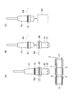
図1に示されるように、実施形態に係るチェーン式工具マガジン1は、一般的なチェーン式工具マガジンと同様に、エンドレスチェーン3を備えている。エンドレスチェーン3は、一対の内リンクプレート5と一対の外リンクプレート7とを、中空軸[hollow shaft]9によって無端状に枢支連結することで構成されている。即ち、内リンクプレート5の端部と外リンクプレート7の端部とは、中空軸9を介して互いに相対的に回動可能に連結されている。例えば、図1中の中央の中空軸9に関して、左方へと延在する内リンクプレート5の右端と右方へと延在する外リンクプレート7の左端とが、当該中空軸9によって互いに相対的に回動可能に連結されている。
中空軸9には、その軸心と平行に中空部11が形成されている。中空部11は、その上端部付近からその下端部付近にかけて等しい直径を有するストレートの深穴(中空部11の直径にほぼ等しい深さ、又は、直径以上の深さ、を有する穴)である。中空部11には、工具ポット15が着脱交換自在に嵌合(嵌入)されている。工具ポット15は、工具ホルダ13を着脱交換自在に備えている。工具ホルダ13は、適宜の工具を備えている。工具ポット15は、の深穴としての中空部11の内周面17と、その全長にかけて嵌合するストレート軸部[straight shaft portion]19を長く備えている。ストレート軸部19の下端側には、ボールプランジャなどの係止部材21が設けられている。
複数の係止部材21が、ストレート軸部19の周方向に等間隔に設けられている。各係止部材21は、ストレート軸部19に内装されたコイルスプリングなどの弾性部材23によって、常に外方(放射外方)に突出するように付勢されている。なお、ストレート軸部19には、係止部材21の抜け落ちを防止するストッパ(図示せず)が設けられている。中空部11の内周面17の下端側の全周にわたって、係止部材21との係止部としての段差部25が形成されている。
工具ポット15のストレート軸部19を中空軸9の中空部11内に上から挿入し、係止部材21が段差部25に達すると、係止部材21は、弾性部材25によってストレート軸部19の外周面から突出されて、段差部(係止部)25と係止される。即ち、工具ポット15が中空部11から安易に抜け出ることが防止される。
また、工具ポット15が係止部材21を支点として中空軸9に対して傾斜したとしても、深穴として形成された中空部11に嵌入されたストレート軸部19の全長が中空部11の内周面17と摺接するので、中空軸9に対する工具ポット15の傾斜は効果的に抑制される。
係止部材21としてのボールプランジャと係止部としての段差部25との関係は相対的なものである。従って、内周面17から突出自在な複数の係止部材21を中空軸9の周方向に設け、かつ、係止部材21と係止自在な周溝を係止部としてストレート軸部19の外周面に設けてもよい。即ち、係止部材21は、中空軸9及びストレート軸部19の一方に設けられ、係止部は、それらの他方に設けられればよい。
工具ポット15の上端部には、上方に開口された環状の係合凹部27が上端面上に形成されている。係合凹部27の内側には、上方に突出する筒状部[cylindrical portion]29が設けられている。筒状部29の周方向に沿って、ボールなどの複数の係止部材31が筒状部29に設けられている。各係止部材31は、筒状部29の径方向(放射方向)に移動自在で、その一部が筒状部29から外部に突出自在に設けられている。ストレート軸部19の軸心部に設けられた収容穴33内には、係止部材31を放射外方向に押圧する押圧部材35が収容されている。押圧部材35は、その上部にテーパ面を有しており、収容穴33内で上下動自在である。
収容穴33の底部には、コイルスプリングなどの弾性部材39が、押圧部材35と上下動可能なスプリング座[spring seat]37との間に弾装されている。弾性部材39の上方への付勢力を調節するために、スプリング座37の上下位置を調節するための調節ねじ41がストレート軸部19に螺合されている。なお、係止部材31が嵌合されている穴は、テーパ状に形成されており、係止部材31が筒状部29から外方に抜け出ないように係止部材31を規制している。
工具ポット15の上部には、中空軸9の上面と当接自在な大径部43が形成されている。大径部43の外周面には、中空軸9に工具ポット15を軸方向(上下方向)に着脱する際に使用される第1アームRA(図2参照)によって保持される保持凹部45が形成されている。
第1アームRAは、後述する機能を備えていれば十分であり、ロボットハンドや自動工具交換装置のATCアーム等である。即ち、第1アームRAは、工具ポット15の着脱交換位置に位置決めされた中空軸9に工具ポット15を装着したり、工具ポット15の着脱交換位置に位置決めされた中空軸9から工具ポット15を分離したりする機能を備えている。また、工作機械の主軸などの工具装着部SP(図2参照)に対して工具交換を行うATCアームAA(図2参照)が所定位置(待機位置)に位置決めされたときに、第1アームRAは、当該所定位置のATCアームAAに保持された工具ホルダ13を、それ自身が保持している工具ポット15に相対的に着脱する機能を備えている。
即ち、第1アームRAは、工具ポット15の着脱交換位置に位置決めされた中空軸9に工具ポット15を装着したり、着脱交換位置に位置決めされた中空軸9から工具ポット15を分離したりする機能と、所定位置に位置決めされたATCアームAAと協働して、工具ポット15に工具ホルダ13を装着したり、工具ポット15から工具ホルダ13を分離したりする機能とを備えている。即ち、第1アームRAは、エンドレスチェーン3に対して接近離反自在であり、かつ、エンドレスチェーン3に設けられた中空軸9の軸方向に移動自在である。また、第1アームRAは、ATCアームAAと協働して工具ホルダ13を交換する待機位置へ移動位置決め自在である。
ATCアームAAは、工作機械の工具装着部SPに工具(工具ホルダ13)を装着したり、工具装着部SPから工具(工具ホルダ13)を分離したりするために、工具装着部SPに対応する位置に位置決め自在である。また、ATCアームAAは、工具マガジンに対して工具の着脱交換を行うために、工具マガジンに対応する位置に位置決め自在である。
また、工具マガジンに工具を装着したり、工具マガジンから工具を分離したりする中間アーム(第1アームRAに相当)を介して工具交換を間接的に行う場合には、ATCアームAAは、中間アームと工具交換を行う待機位置と、工具装着部SPに対応する位置とに位置決め自在である。
本実施形態においては、工具ポット15が中空軸9から離脱された後に、工具ポット15に保持されている工具ホルダ13が工具ポット15から離脱され、離脱された工具ホルダ13が工作機械の工具装着部SPに装着される。従って、ATCアームAAは、第1アームRAに保持された工具ポット15から工具ホルダ13を離脱させるために、工具ポット15の待機位置(上述した所定位置)と工作機械の工具装着部SPに対応する位置との間を往復動自在である。工具ポット15の待機位置は、第1アームRAによって中空軸9から離脱された工具ポット15からATCアームAAによって工具ホルダ13を離脱させるための位置である。
なお、工具ポット15に対して工具ホルダ13の着脱を行うために、工具ホルダ13の基端部には、図1に示されるように、工具ポット15の係合凹部27に対して嵌合離脱自在な装着部として環状係合部47が設けられている。環状係合部47の外周面は僅かなテーパ面を形成されている。環状係合部47が係合凹部27と嵌合するときには、両者はテーパ嵌合する。また、環状係合部47の内周面の全周に亘って、筒状部29に設けられた係止部材31と係止するテーパ状の係止段部49が形成されている。
従って、環状係合部47が係合凹部27と嵌合した状態では、環状係合部47の外周面と係合凹部27の内周面とがテーパ嵌合する。また、弾性部材39の付勢力によって上方に押圧付勢されている押圧部材35のテーパ面によって外方へ移動された係止部材31が係止段部49を係止する。この結果、工具ホルダ13が工具ポット15に固定される。
工具ポット15から工具ホルダ13を離脱するには、工具ポット15から工具ホルダ13を上方に引き抜く。この際、係止部材31を、弾性部材39の付勢力に抗して、筒状部29の内方に押圧する必要がある。従って、工具ポット15から工具ホルダ13を引き抜くには大きな力を要する。
一方、中空軸9の中空部11から工具ポット15を引き抜き離脱するときには、係止部材21を、弾性部材23の付勢力に抗して、ストレート軸部19内に没入させる。ストレートの穴である中空部11にストレート軸部19が嵌合されているので、工具ポット15を中空軸9から容易に離脱させることができる。この際、第1アームRAによって工具ポット15の保持凹部45が保持されて、工具ポット15が、中空軸9の軸心に平行に移動される。従って、工具ポット15の離脱は容易に行うことができる。
中空軸9の中空部11と工具ポット15のストレート軸部19とは全長にかけてストレートに嵌合するので、例えば手で工具ポット15を中空軸9から離脱するとき、工具ポット15を傾斜させることなく離脱できる。従って、隣接した工具ポット15が互いに干渉するようなことがない。また、中空軸9のピッチをより小さくすることができる。即ち、より多くの中空軸9を設けることができる。
また、長いストレートな穴である中空部11に工具ポット15の長いストレート軸部19が嵌合されるので、中空軸9の軸心に対して工具ポット15の軸心が傾斜するのを抑制できる。従って、中空軸9と工具ポット15との位置的関係を常に正確に維持できる。さらに、係止部材21の付勢力は比較的小さくてよいので、手で工具ポット15を中空軸9に対して容易に着脱でき、第1アームRAによっても工具ポット15を中空軸9に対して正確かつ容易に着脱できる。
工具ホルダ13には、ATCアームAAによって自動交換される一般的な工具と同様に、ATCアームAAによって保持されるアーム係合部51が設けられている。工具ポット15に対する工具ホルダ13の着脱、及び、工作機械の主軸などの工具装着部SPに対する工具ホルダ13の着脱は、ATCアームAAによって行われる。従って、第1アームRAによって中空軸9から工具ポット15を離脱するには、ATCアームAAによって、第1アームRAに保持されている工具ポット15に対して工具ホルダ13を着脱する。
本実施形態によれば、エンドレスチェーン3の内リンクプレート5と外リンクプレート7とを枢支連結する中空軸9の中空部11に対する工具ポット15の着脱は、中空部11の軸心に平行な方向に行なわれる。そして、中空部11から離脱された工具ポット15に対する工具ホルダ13の着脱は、中空軸9から離れた位置で行われる。従って、工具ポット15と工具ホルダ13とが強固に嵌合していても、内リンクプレート5及び外リンクプレート7や中空軸9に悪影響を与えることなく、工具ポット15から工具ホルダ13を離脱させることができる。
また、エンドレスチェーン3に対して接近離反する方向に移動自在で、かつ、中空軸9の軸心と平行な方向に移動自在な第1アームRAによって、中空軸9から工具ポット15が離脱される。そして、第1アームRAによって保持されている工具ポット15の待機位置と工具装着部SPに対応する位置との間を往復動自在なATCアームAAによって、工具ポット15に保持されている工具ホルダ13を保持して、工具ホルダ13を工具ポット15から離脱させる。従って、工具ポット15と工具ホルダ13とが強固に嵌合していても、工具ポット15からの工具ホルダ13を容易に離脱させることができる。
また、エンドレスチェーン3の内リンクプレート5と外リンクプレート7とを枢支連結する中空軸9の中空部11に、係止部25が設けられているので、チェーン式工具マガジンの構成を簡素化できる。
なお、本発明は、上記実施形態のみに限定されず、適宜変形して他の形態で実施し得る。例えば、上記実施形態では、工具ポット15は、エンドレスチェーン3の中空軸9に上下方向に着脱された。しかし、工具ポット15の着脱方向(中空軸9の軸方向)は水平方向又は斜め方向でもよい。
本発明の特徴は以下のように定義することもできる。
1.チェーン式工具マガジンから工作機械の工具装着部への工具装着方法であって、
チェーン式工具マガジンのエンドレスチェーンの内リンクプレートと外リンクプレートとを枢支連結する中空軸の中空部に対して当該中空軸の軸方向に着脱自在な工具ポットを、前記中空部から離脱させ、
前記中空部から離脱された前記工具ポットに着脱自在に備えられた工具を、上記工具ポットから離脱させ、
前記工具ポットから離脱された前記工具を、前記工具装着部に装着する、工具装着方法。
2. 上記1に記載の工具装着方法であって、
前記中空軸からの前記工具ポットの離脱が、前記エンドレスチェーンに対して接近離反自在で、かつ、前記軸方向に移動自在に設けられた第1アームによって行なわれ、
前記工具ポットからの前記工具の離脱が、前記工具装着部の位置と前記工具ポットの待機位置との間を往復動自在なATCアームによって行なわれる、工具装着方法。
3. 複数の工具を着脱自在なチェーン式工具マガジンであって、
複数の内リンクプレート及び複数の外リンクプレートが連結されて形成されたエンドレスチェーンと、
前記複数の内リンクプレートのそれぞれと前記外リンクプレートのそれぞれとを枢支連結する中空軸と、
前記中空軸に着脱可能で、工具が着脱される工具ポットとを備えており、
前記工具ポットを着脱自在な中空部が前記中空軸に設けられ、
前記工具ポットを係止自在な係止部が前記中空部に設けられている、チェーン式工具マガジン。
4. 上記3に記載のチェーン式工具マガジンであって、
前記中空部が、ストレートの深穴として形成されている、チェーン式工具マガジン。
1.チェーン式工具マガジンから工作機械の工具装着部への工具装着方法であって、
チェーン式工具マガジンのエンドレスチェーンの内リンクプレートと外リンクプレートとを枢支連結する中空軸の中空部に対して当該中空軸の軸方向に着脱自在な工具ポットを、前記中空部から離脱させ、
前記中空部から離脱された前記工具ポットに着脱自在に備えられた工具を、上記工具ポットから離脱させ、
前記工具ポットから離脱された前記工具を、前記工具装着部に装着する、工具装着方法。
2. 上記1に記載の工具装着方法であって、
前記中空軸からの前記工具ポットの離脱が、前記エンドレスチェーンに対して接近離反自在で、かつ、前記軸方向に移動自在に設けられた第1アームによって行なわれ、
前記工具ポットからの前記工具の離脱が、前記工具装着部の位置と前記工具ポットの待機位置との間を往復動自在なATCアームによって行なわれる、工具装着方法。
3. 複数の工具を着脱自在なチェーン式工具マガジンであって、
複数の内リンクプレート及び複数の外リンクプレートが連結されて形成されたエンドレスチェーンと、
前記複数の内リンクプレートのそれぞれと前記外リンクプレートのそれぞれとを枢支連結する中空軸と、
前記中空軸に着脱可能で、工具が着脱される工具ポットとを備えており、
前記工具ポットを着脱自在な中空部が前記中空軸に設けられ、
前記工具ポットを係止自在な係止部が前記中空部に設けられている、チェーン式工具マガジン。
4. 上記3に記載のチェーン式工具マガジンであって、
前記中空部が、ストレートの深穴として形成されている、チェーン式工具マガジン。
日本国特許出願第2015-80750号(2015年4月10日出願)の全ての内容は、ここに参照されることで本明細書に援用される。本発明の実施形態を参照することで上述のように本発明が説明されたが、本発明は上述した実施形態に限定されるものではない。本発明の範囲は、請求の範囲に照らして決定される。
Claims (4)
- 工作機械における工具装着部への工具装着方法であって、
エンドレスチェーンの内リンクプレートと外リンクプレートとを枢支連結する中空軸の中空部に対して軸方向に着脱自在な工具ポットを、前記中空軸の前記中空部から離脱させた後、
この工具ポットに着脱自在に備えられた工具を、上記工具ポットから離脱させ、
この離脱した工具の装着部を、工作機械に備えた工具装着部へ装着する、工具装着方法。 - 請求項1に記載の工具装着方法であって、
前記中空軸からの工具ポットの離脱は、前記エンドレスチェーンに対して接近離反自在で、かつ、前記中空軸の軸方向に移動自在に設けられた第1アームによって行なわれ、
前記工具ポットからの工具の離脱は、前記工作機械の工具装着部に対応する位置と前記工具ポットの待機位置との間を往復動自在なATCアームによって行なわれる、工具装着方法。 - 複数の工具を着脱自在なチェーン式工具マガジンであって、
内リンクプレートと外リンクプレートとを枢支連結する中空軸を備え、
工具を着脱自在に備えた工具ポットを嵌合離脱自在な中空部を前記中空軸に備え、
前記工具ポットに備えた係止部材を係止自在な係止部を前記中空部に備えている、チェーン式工具マガジン。 - 請求項3に記載のチェーン式工具マガジンであって、
前記中空軸の前記中空部が、ストレートの深穴として形成されている、チェーン式工具マガジン。
Applications Claiming Priority (2)
| Application Number | Priority Date | Filing Date | Title |
|---|---|---|---|
| JP2015080750A JP5956010B1 (ja) | 2015-04-10 | 2015-04-10 | 工具装着方法及びチェーン式工具マガジン並びに工具自動交換装置 |
| JP2015-080750 | 2015-04-10 |
Publications (1)
| Publication Number | Publication Date |
|---|---|
| WO2016163144A1 true WO2016163144A1 (ja) | 2016-10-13 |
Family
ID=56425675
Family Applications (1)
| Application Number | Title | Priority Date | Filing Date |
|---|---|---|---|
| PCT/JP2016/053514 Ceased WO2016163144A1 (ja) | 2015-04-10 | 2016-02-05 | 工具装着方法、及び、チェーン式工具マガジン |
Country Status (2)
| Country | Link |
|---|---|
| JP (1) | JP5956010B1 (ja) |
| WO (1) | WO2016163144A1 (ja) |
Cited By (1)
| Publication number | Priority date | Publication date | Assignee | Title |
|---|---|---|---|---|
| CN116475842A (zh) * | 2023-05-09 | 2023-07-25 | 冈田智能(江苏)股份有限公司 | 一种刀套外圆截面偏差检测装置、方法及链式刀库 |
Families Citing this family (1)
| Publication number | Priority date | Publication date | Assignee | Title |
|---|---|---|---|---|
| CN107738220A (zh) * | 2017-11-16 | 2018-02-27 | 常州机电职业技术学院 | 一种轴向动力刀座刀具拆卸装置 |
Citations (5)
| Publication number | Priority date | Publication date | Assignee | Title |
|---|---|---|---|---|
| EP0860234A2 (en) * | 1997-02-07 | 1998-08-26 | REGINA INDUSTRIA S.p.A. | Tool and toolholder coupling device |
| US6343903B1 (en) * | 1999-11-03 | 2002-02-05 | Industrial Technology Research Institute | Tool holder of hollow taper shank in tool machine |
| JP2007144587A (ja) * | 2005-11-29 | 2007-06-14 | Tsubakimoto Chain Co | ツール保持搬送チェーン |
| JP2012115953A (ja) * | 2010-12-01 | 2012-06-21 | Tsubakimoto Chain Co | 工具ポット |
| JP2014205203A (ja) * | 2013-04-10 | 2014-10-30 | 株式会社椿本チエイン | チェーン用工具ポット |
-
2015
- 2015-04-10 JP JP2015080750A patent/JP5956010B1/ja not_active Expired - Fee Related
-
2016
- 2016-02-05 WO PCT/JP2016/053514 patent/WO2016163144A1/ja not_active Ceased
Patent Citations (5)
| Publication number | Priority date | Publication date | Assignee | Title |
|---|---|---|---|---|
| EP0860234A2 (en) * | 1997-02-07 | 1998-08-26 | REGINA INDUSTRIA S.p.A. | Tool and toolholder coupling device |
| US6343903B1 (en) * | 1999-11-03 | 2002-02-05 | Industrial Technology Research Institute | Tool holder of hollow taper shank in tool machine |
| JP2007144587A (ja) * | 2005-11-29 | 2007-06-14 | Tsubakimoto Chain Co | ツール保持搬送チェーン |
| JP2012115953A (ja) * | 2010-12-01 | 2012-06-21 | Tsubakimoto Chain Co | 工具ポット |
| JP2014205203A (ja) * | 2013-04-10 | 2014-10-30 | 株式会社椿本チエイン | チェーン用工具ポット |
Cited By (2)
| Publication number | Priority date | Publication date | Assignee | Title |
|---|---|---|---|---|
| CN116475842A (zh) * | 2023-05-09 | 2023-07-25 | 冈田智能(江苏)股份有限公司 | 一种刀套外圆截面偏差检测装置、方法及链式刀库 |
| CN116475842B (zh) * | 2023-05-09 | 2023-09-29 | 冈田智能(江苏)股份有限公司 | 一种刀套外圆截面偏差检测装置、方法及链式刀库 |
Also Published As
| Publication number | Publication date |
|---|---|
| JP2016198853A (ja) | 2016-12-01 |
| JP5956010B1 (ja) | 2016-07-20 |
Similar Documents
| Publication | Publication Date | Title |
|---|---|---|
| JP5014352B2 (ja) | ワーク保持装置、及び、このワーク保持装置を備えた工作機械 | |
| US8376670B2 (en) | Spindle head device and machine tool | |
| JP2010264507A (ja) | パンチ金型及び潤滑油の供給方法 | |
| JP2016198879A (ja) | 工具自動交換装置 | |
| JP5452049B2 (ja) | 工作機械 | |
| US20180229310A1 (en) | Chuck device | |
| JP5956010B1 (ja) | 工具装着方法及びチェーン式工具マガジン並びに工具自動交換装置 | |
| CN100522428C (zh) | 工具松开装置 | |
| KR101488256B1 (ko) | 보철물 가공기의 자동 툴 교환을 위한 툴 보관대 | |
| JP6071642B2 (ja) | パンチ金型 | |
| WO2010106902A1 (ja) | ダイホルダ取付構造 | |
| JP5430541B2 (ja) | 工具ポット | |
| JP2014237175A (ja) | パンチ金型 | |
| JP6430893B2 (ja) | クランプ装置 | |
| JP5850141B2 (ja) | プレスブレーキの金型ホルダ | |
| JP6147622B2 (ja) | 工具マガジン装置及び工作機械 | |
| KR20090046336A (ko) | 자동공구교환장치의 공구매거진용 공구 포트 | |
| JP5202237B2 (ja) | 工具クランプ装置の先端側ドローバー交換装置 | |
| KR101576297B1 (ko) | 터닝 센터용 보링 바 홀더 장치 | |
| JP2019042839A (ja) | 工作機械 | |
| JP6476537B2 (ja) | 工作機械及び工具ホルダ | |
| JP5184429B2 (ja) | パンチ金型 | |
| KR20080051915A (ko) | 공구 어댑터 | |
| JP2012250290A (ja) | パンチ金型 | |
| JP6420033B2 (ja) | ワーク当接ユニットおよび工作機械 |
Legal Events
| Date | Code | Title | Description |
|---|---|---|---|
| 121 | Ep: the epo has been informed by wipo that ep was designated in this application |
Ref document number: 16776313 Country of ref document: EP Kind code of ref document: A1 |
|
| NENP | Non-entry into the national phase |
Ref country code: DE |
|
| 122 | Ep: pct application non-entry in european phase |
Ref document number: 16776313 Country of ref document: EP Kind code of ref document: A1 |