WO2016162980A1 - 画像処理装置、撮像装置、画像処理方法およびプログラム - Google Patents
画像処理装置、撮像装置、画像処理方法およびプログラム Download PDFInfo
- Publication number
- WO2016162980A1 WO2016162980A1 PCT/JP2015/061005 JP2015061005W WO2016162980A1 WO 2016162980 A1 WO2016162980 A1 WO 2016162980A1 JP 2015061005 W JP2015061005 W JP 2015061005W WO 2016162980 A1 WO2016162980 A1 WO 2016162980A1
- Authority
- WO
- WIPO (PCT)
- Prior art keywords
- light
- narrowband
- filter
- band
- pixel
- Prior art date
- Legal status (The legal status is an assumption and is not a legal conclusion. Google has not performed a legal analysis and makes no representation as to the accuracy of the status listed.)
- Ceased
Links
Images





Classifications
-
- G—PHYSICS
- G06—COMPUTING OR CALCULATING; COUNTING
- G06V—IMAGE OR VIDEO RECOGNITION OR UNDERSTANDING
- G06V40/00—Recognition of biometric, human-related or animal-related patterns in image or video data
- G06V40/10—Human or animal bodies, e.g. vehicle occupants or pedestrians; Body parts, e.g. hands
- G06V40/16—Human faces, e.g. facial parts, sketches or expressions
- G06V40/161—Detection; Localisation; Normalisation
-
- A—HUMAN NECESSITIES
- A61—MEDICAL OR VETERINARY SCIENCE; HYGIENE
- A61B—DIAGNOSIS; SURGERY; IDENTIFICATION
- A61B5/00—Measuring for diagnostic purposes; Identification of persons
- A61B5/0059—Measuring for diagnostic purposes; Identification of persons using light, e.g. diagnosis by transillumination, diascopy, fluorescence
- A61B5/0077—Devices for viewing the surface of the body, e.g. camera, magnifying lens
-
- G—PHYSICS
- G06—COMPUTING OR CALCULATING; COUNTING
- G06T—IMAGE DATA PROCESSING OR GENERATION, IN GENERAL
- G06T7/00—Image analysis
- G06T7/0002—Inspection of images, e.g. flaw detection
- G06T7/0012—Biomedical image inspection
-
- G—PHYSICS
- G06—COMPUTING OR CALCULATING; COUNTING
- G06V—IMAGE OR VIDEO RECOGNITION OR UNDERSTANDING
- G06V10/00—Arrangements for image or video recognition or understanding
- G06V10/20—Image preprocessing
- G06V10/30—Noise filtering
-
- G—PHYSICS
- G06—COMPUTING OR CALCULATING; COUNTING
- G06V—IMAGE OR VIDEO RECOGNITION OR UNDERSTANDING
- G06V10/00—Arrangements for image or video recognition or understanding
- G06V10/40—Extraction of image or video features
- G06V10/56—Extraction of image or video features relating to colour
-
- A—HUMAN NECESSITIES
- A61—MEDICAL OR VETERINARY SCIENCE; HYGIENE
- A61B—DIAGNOSIS; SURGERY; IDENTIFICATION
- A61B5/00—Measuring for diagnostic purposes; Identification of persons
- A61B5/0059—Measuring for diagnostic purposes; Identification of persons using light, e.g. diagnosis by transillumination, diascopy, fluorescence
- A61B5/0075—Measuring for diagnostic purposes; Identification of persons using light, e.g. diagnosis by transillumination, diascopy, fluorescence by spectroscopy, i.e. measuring spectra, e.g. Raman spectroscopy, infrared absorption spectroscopy
-
- A—HUMAN NECESSITIES
- A61—MEDICAL OR VETERINARY SCIENCE; HYGIENE
- A61B—DIAGNOSIS; SURGERY; IDENTIFICATION
- A61B5/00—Measuring for diagnostic purposes; Identification of persons
- A61B5/02—Detecting, measuring or recording for evaluating the cardiovascular system, e.g. pulse, heart rate, blood pressure or blood flow
- A61B5/021—Measuring pressure in heart or blood vessels
- A61B5/02108—Measuring pressure in heart or blood vessels from analysis of pulse wave characteristics
- A61B5/02125—Measuring pressure in heart or blood vessels from analysis of pulse wave characteristics of pulse wave propagation time
-
- A—HUMAN NECESSITIES
- A61—MEDICAL OR VETERINARY SCIENCE; HYGIENE
- A61B—DIAGNOSIS; SURGERY; IDENTIFICATION
- A61B5/00—Measuring for diagnostic purposes; Identification of persons
- A61B5/02—Detecting, measuring or recording for evaluating the cardiovascular system, e.g. pulse, heart rate, blood pressure or blood flow
- A61B5/024—Measuring pulse rate or heart rate
- A61B5/02416—Measuring pulse rate or heart rate using photoplethysmograph signals, e.g. generated by infrared radiation
-
- A—HUMAN NECESSITIES
- A61—MEDICAL OR VETERINARY SCIENCE; HYGIENE
- A61B—DIAGNOSIS; SURGERY; IDENTIFICATION
- A61B5/00—Measuring for diagnostic purposes; Identification of persons
- A61B5/145—Measuring characteristics of blood in vivo, e.g. gas concentration or pH-value ; Measuring characteristics of body fluids or tissues, e.g. interstitial fluid or cerebral tissue
- A61B5/1455—Measuring characteristics of blood in vivo, e.g. gas concentration or pH-value ; Measuring characteristics of body fluids or tissues, e.g. interstitial fluid or cerebral tissue using optical sensors, e.g. spectral photometrical oximeters
- A61B5/14551—Measuring characteristics of blood in vivo, e.g. gas concentration or pH-value ; Measuring characteristics of body fluids or tissues, e.g. interstitial fluid or cerebral tissue using optical sensors, e.g. spectral photometrical oximeters for measuring blood gases
-
- G—PHYSICS
- G02—OPTICS
- G02B—OPTICAL ELEMENTS, SYSTEMS OR APPARATUS
- G02B5/00—Optical elements other than lenses
- G02B5/20—Filters
- G02B5/201—Filters in the form of arrays
-
- G—PHYSICS
- G02—OPTICS
- G02B—OPTICAL ELEMENTS, SYSTEMS OR APPARATUS
- G02B5/00—Optical elements other than lenses
- G02B5/20—Filters
- G02B5/208—Filters for use with infrared or ultraviolet radiation, e.g. for separating visible light from infrared and/or ultraviolet radiation
-
- G—PHYSICS
- G06—COMPUTING OR CALCULATING; COUNTING
- G06T—IMAGE DATA PROCESSING OR GENERATION, IN GENERAL
- G06T2207/00—Indexing scheme for image analysis or image enhancement
- G06T2207/30—Subject of image; Context of image processing
- G06T2207/30004—Biomedical image processing
Definitions
- the present invention relates to an image processing device, an imaging device, an image processing method, and a program for generating vital information such as a living body based on image data.
- vital information such as heart rate, oxygen saturation and blood pressure is used as information for grasping the human health condition, and the health condition of the subject is grasped.
- a technique is known in which a living body irradiated with red light and near-infrared light is imaged by an image sensor, and the oxygen saturation of the living body is calculated based on image data generated by the image sensor.
- the oxygen saturation of the living body is calculated based on the light absorption degree by the living body calculated according to the image data generated by the image sensor and the temporal change in the light absorption degree.
- JP 2013-118978 A Japanese Patent Laid-Open No. 9-262213
- Patent Documents 1 and 2 described above a light source that emits red light and near-infrared light, respectively, is required.
- the present invention has been made in view of the above, and an object thereof is to provide an image processing apparatus, an imaging apparatus, an image processing method, and a program that can be reduced in size.
- an image processing apparatus has a narrow band light having a narrower wavelength band than the primary color wavelength band and having a maximum transmission spectrum in the visible light band.
- a first narrowband filter that transmits light; a second narrowband filter that transmits a narrowband light having a wavelength band narrower than the wavelength band of the primary color and having a maximum transmission spectrum in a visible light band different from the narrowband filter;
- a third narrow band filter that transmits a narrow band light having a maximum transmission spectrum in a non-visible light band, and forming a predetermined array pattern, and a plurality of individual narrow band filters forming the array pattern
- An acquisition unit that acquires image data generated by an image sensor disposed at a position corresponding to any one of the pixels, and an environment in which the image sensor generates the image data.
- a determination unit that determines whether or not the light amount of the invisible light band is greater than a threshold value, and the determination unit determines that the light amount of the invisible light band is equal to or greater than the threshold value.
- the vital information of the subject is generated using the pixel value corresponding to the position of the pixel where the third narrowband filter is disposed and the pixel value corresponding to the position of the pixel where the second narrowband filter is disposed in the image to be processed
- the determination unit determines that the amount of light in the invisible light band is not equal to or greater than the threshold, the pixel value corresponding to the position of the pixel in which the first narrowband filter is arranged in the image corresponding to the image data
- a generating unit that generates vital information of a subject using a pixel value corresponding to a pixel position where the second narrowband filter is arranged.
- the image processing apparatus is the image processing apparatus according to the above invention, wherein the determination unit is based on a pixel value corresponding to a position of an image in which the third narrowband filter is disposed in an image corresponding to the data. It is characterized by determining whether the light quantity of a non-visible light band is larger than the said threshold value.
- the image processing apparatus further includes a detection unit that detects light in the non-visible light band around the image processing apparatus in the above invention, and the determination unit detects the detection detected by the detection unit. Based on the result, it is determined whether or not the amount of light in the invisible light band is larger than the threshold value.
- the imaging element is a broadband filter that transmits one of light in a red wavelength band, light in a green wavelength band, and light in a blue wavelength band.
- a predetermined array pattern using the first narrowband filter, the second narrowband filter, and the third narrowband filter, and each filter forming the array pattern includes a plurality of pixels. It is arrange
- the determination unit divides the image into a plurality of regions, and the component of the invisible light band is larger than the threshold for each of the plurality of regions.
- the generation unit generates the vital information for each of the plurality of regions.
- the image processing apparatus is the image processing apparatus according to the above invention, wherein the determination unit has a component of the invisible light band larger than the threshold for a partial region that is a part of an image corresponding to the image data.
- the generation unit generates the vital information for the partial area.
- the image processing apparatus further includes a face detection unit that detects a face of a subject included in the image corresponding to the image data, and the determination unit is detected by the face detection unit. It is characterized by determining whether the component of the invisible light band is larger than the threshold for the region including the face.
- the first narrowband filter transmits narrowband light included in a part of a green wavelength band
- the second narrowband filter is red.
- Narrow band light included in a part of the wavelength band is transmitted
- the third narrow band filter transmits narrow band light included in a part of the near infrared wavelength band.
- the first narrowband filter transmits narrowband light having a wavelength band of 490 to 550 nm
- the second narrowband filter has a wavelength band.
- Narrowband light included in 620 to 700 nm is transmitted
- the third narrowband filter transmits narrowband light included in a wavelength band of 800 to 1000 nm.
- the vital information is any one of oxygen saturation, heart rate, and blood pressure.
- an imaging apparatus includes the above-described image processing apparatus and the imaging element.
- the image processing method according to the present invention is an image processing method executed by the image processing apparatus, which has a narrower wavelength band than the primary wavelength band and has a maximum transmission spectrum in the visible light band.
- a third narrowband filter that transmits a narrowband light having a maximum transmission spectrum in a non-visible light band, and forming a predetermined array pattern, and each narrowband filter that forms the array pattern includes: An acquisition step of acquiring image data generated by an image sensor arranged at a position corresponding to any of a plurality of pixels, and when the image sensor generates the image data A determination step of determining whether the amount of light in the invisible light band under an environment is greater than a threshold value, and the image data when the determination step determines that the component of the invisible light band is greater than or equal to the threshold value; The vital information of the subject is obtained using the pixel value corresponding to the position of the pixel in which the third narrowband filter is disposed and the pixel value corresponding to the position of the pixel in which the second narrowband filter is disposed in the image corresponding to.
- the determination step determines whether the light amount in the invisible light band is not equal to or greater than the threshold, it corresponds to the position of the pixel in which the first narrowband filter is arranged in the image corresponding to the image data.
- the program according to the present invention includes a first narrowband filter that transmits a narrowband light having a wavelength band narrower than the primary color wavelength band and having a maximum transmission spectrum in the visible light band, and a primary color wavelength band.
- a third narrow band filter that transmits band light and a predetermined array pattern are formed, and each narrow band filter that forms the array pattern is arranged at a position corresponding to one of a plurality of pixels
- An acquisition step of acquiring image data generated by an element, and a light amount of the invisible light band in an environment when the image sensor generates the image data is a threshold value.
- the vital value of the subject is generated using the pixel value corresponding to the pixel position and the pixel value corresponding to the pixel position where the second narrowband filter is disposed, while the invisible light band is determined by the determination step. Is determined to be not greater than or equal to the threshold value, the pixel value corresponding to the position of the pixel in which the first narrowband filter is disposed in the image corresponding to the image data and the second narrowband filter are disposed.
- FIG. 1 is a block diagram showing a schematic configuration of an imaging apparatus according to Embodiment 1 of the present invention.
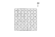
- FIG. 2 is a diagram schematically showing the configuration of the filter array provided in the image sensor according to Embodiment 1 of the present invention.
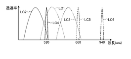
- FIG. 3 is a diagram showing an example of spectral sensitivity characteristics of each filter constituting the filter array provided in the image sensor according to Embodiment 1 of the present invention.
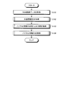
- FIG. 4 is a flowchart showing an outline of processing executed by the image processing unit according to Embodiment 1 of the present invention.
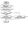
- FIG. 5 is a flowchart showing an outline of the light source information determination process of FIG.
- FIG. 6 is a flowchart showing an overview of the vital information generation filter selection process of FIG.
- FIG. 1 is a block diagram showing a schematic configuration of an imaging apparatus according to Embodiment 1 of the present invention.
- FIG. 2 is a diagram schematically showing the configuration of the filter array provided in the image sensor according to Embodiment 1 of the
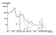
- FIG. 7 is a diagram showing the absorption characteristics of hemoglobin.
- FIG. 8 is a flowchart showing an overview of the vital information generation process of FIG.
- FIG. 9 is a diagram illustrating an example of an image corresponding to the RAW image data generated by the imaging unit according to Embodiment 1 of the present invention.
- FIG. 10 is a diagram schematically illustrating time-series fluctuations of pixel values of pixels corresponding to the narrowband filter selected by the selection unit of the image processing unit according to Embodiment 1 of the present invention.
- FIG. 11 is a diagram schematically showing the configuration of the filter array of the image sensor according to Embodiment 2 of the present invention.
- FIG. 12 is a diagram showing an example of spectral sensitivity characteristics of each filter constituting the filter array provided in the image sensor according to Embodiment 2 of the present invention.
- FIG. 13 is a flowchart showing an outline of light source information determination processing executed by the image processing unit according to Embodiment 2 of the present invention.
- FIG. 14 is a diagram illustrating an example of an image corresponding to the RAW image data generated by the imaging unit according to Embodiment 2 of the present invention.
- FIG. 15 is a block diagram showing a functional configuration of the imaging apparatus according to Embodiment 3 of the present invention.
- FIG. 16 is a block diagram showing a functional configuration of an imaging apparatus according to Embodiment 4 of the present invention.
- FIG. 17 is a diagram showing the relationship between the light source spectrum and the sensitivity.
- FIG. 1 is a block diagram showing a schematic configuration of an imaging apparatus according to Embodiment 1 of the present invention.
- An imaging apparatus 1 illustrated in FIG. 1 captures a subject, generates RAW image data of the subject, acquires RAW image data generated by the imaging unit 2, and performs predetermined processing on the acquired RAW image data.
- An image processing unit 3 that performs processing, and a display unit 4 that displays an image corresponding to the RAW image data processed by the image processing unit 3 are provided.
- the image processing unit 3 functions as an image processing apparatus.
- the imaging unit 2, the image processing unit 3, and the display unit 4 are connected so as to be capable of bidirectional communication by wire or wireless.
- the imaging unit 2 includes an optical system 21, an imaging element 22, and an A / D conversion unit 23.
- the optical system 21 is configured by using one or a plurality of lenses, for example, a focus lens, a zoom lens, a diaphragm, a shutter, and the like, and forms a subject image on the light receiving surface of the image sensor 22.
- the image sensor 22 generates RAW image data by receiving the subject image formed on the light receiving surface by the optical system 21 and performing photoelectric conversion.
- the image pickup device 22 is configured using a CMOS (Complementary Metal Oxide Semiconductor) that photoelectrically converts light received by each of a plurality of pixels arranged in a lattice shape and generates an electrical signal.
- CMOS Complementary Metal Oxide Semiconductor
- the image sensor 22 includes a plurality of wideband filters that transmit light in the primary color wavelength band, and a plurality of narrowband filters that transmit light in a narrow band narrower than the wavelength band of the light transmitted through the broadband filter. It has a filter array (CFA).
- CFA filter array
- FIG. 2 is a diagram schematically showing the configuration of the filter array.
- the filter array 221 shown in FIG. 2 is disposed on the light receiving surface of each pixel constituting the image sensor 22, and is a broadband filter C1 that transmits green light (495 to 570 nm), and transmits blue light (450 to 495 nm).
- a broadband filter C2 a broadband filter C3 that transmits red light (620 to 750 nm), and a narrowband filter that has a maximum value in a part of the green wavelength band and transmits light components narrower than the green wavelength band.
- the filter array 221 the total number of wideband filters C1, wideband filters C2, and wideband filters C2 is greater than the total number of narrowband filters C4, narrowband filters C5, and narrowband filters C6.
- the filter array 221 is arranged at the position of a pixel that has advanced three pixels to the right and then one downward when viewed with one narrowband filter as a reference.
- the filter array 221 proceeds to the right in the order of the wideband filter C1, the wideband filter C3, and the wideband filter C1 when viewed from the narrowband filter C4 at the upper left end of FIG.
- a narrow-band filter C5 is provided in each pixel.
- FIG. 3 is a diagram illustrating an example of spectral sensitivity characteristics of each filter constituting the filter array 221.
- the horizontal axis indicates the wavelength
- the vertical axis indicates the transmittance.
- a curve LC1 indicates the transmittance of the broadband filter C1
- a curve LC2 indicates the transmittance of the broadband filter C2
- a curve LC3 indicates the transmittance of the broadband filter C3
- a curve LC4 indicates the transmittance of the narrowband filter C4.
- the curve LC5 shows the transmittance of the narrowband filter C5
- the curve LC6 shows the transmittance of the narrowband filter C6.
- the narrowband filter C4 transmits narrowband light included in a part of the green wavelength band. Specifically, the narrow band filter C4 transmits narrow band light having a wavelength band of 490 to 550 nm. More preferably, the narrow band filter C4 transmits light of 520 nm.
- the narrow band filter C5 transmits narrow band light included in a part of the red wavelength band. Specifically, the narrowband filter C5 transmits narrowband light having a wavelength band of 620 to 700 nm. More preferably, the narrow band filter C5 transmits light of 660 nm. Further, the narrow band filter C6 transmits narrow band light included in a part of the near infrared wavelength band.
- the narrow band filter C6 transmits narrow band light having a wavelength band of 800 to 1000 nm. More preferably, the narrow band filter C6 transmits light of 940 nm.
- the transmission spectrum transmitted by the narrowband filter C4 is 520 nm
- the transmission spectrum transmitted by the narrowband filter C5 is 660 nm
- the transmission spectrum transmitted by the narrowband filter C6 is 940 nm.
- the A / D converter 23 converts the analog RAW image data generated by the image sensor 22 into digital.
- the image processing unit 3 includes an acquisition unit 31, a determination unit 32, a selection unit 33, a generation unit 34, and a face detection unit 35.
- the acquisition unit 31 acquires the RAW image data generated by the imaging device 22 from the imaging unit 2, and outputs the acquired RAW image data to the determination unit 32, the generation unit 34, and the face detection unit 35, respectively.
- the determination unit 32 determines whether or not the amount of light in the invisible light band under the environment when the image sensor 22 generates image data is greater than a threshold value. Specifically, the determination unit 32 determines whether near-infrared information is included in the RAW image data acquired by the acquisition unit 31 from the imaging unit 2. For example, the determination unit 32 extracts the pixel value of the corresponding pixel corresponding to the position of the pixel where the narrowband filter C6 is arranged in the image corresponding to the RAW image data acquired by the acquisition unit 31 from the imaging unit 2, and then The average value of the pixel values of the pixels corresponding to the extracted narrowband filter C6 is calculated, and it is determined whether or not the calculated average value is larger than the threshold value. It is determined whether or not the amount of light in the invisible light band (near infrared information) is greater than a threshold.
- the selection unit 33 selects a narrowband filter used when the generation unit 34 generates vital information based on the determination result of the determination unit 32. Specifically, when the determination unit 32 determines that the near-infrared information is sufficiently included in the RAW image data, the selection unit 33 serves as a narrowband filter (band) used by the generation unit 34 to generate vital information. If the narrowband filter C6 is selected and the determination unit 32 determines that the near-infrared information is not sufficiently included in the RAW image data, the narrowband filter C4 is used as the narrowband filter used by the generation unit 34 to generate vital information. Select.
- the generation unit 34 Based on the selection result of the selection unit 33, the RAW image data acquired by the acquisition unit 31 from the imaging unit 2, and the detection result of the face detection unit 35, the generation unit 34 detects the subject included in the RAW image corresponding to the RAW image data. Vital information of a face area including a face is generated. Here, vital information is any of oxygen saturation, heart rate, and blood pressure. Specifically, when the determination unit 32 determines that the component of the invisible light band is equal to or greater than the threshold, the generation unit 34 uses the narrowband filter C4 in the image corresponding to the RAW image data generated by the image sensor 22.
- Vital information of the subject is generated using the pixel value corresponding to the position of the pixel where the pixel is disposed and the pixel value corresponding to the position of the pixel where the narrowband filter C5 is disposed.
- the pixel value corresponding to the position of the pixel where the narrowband filter C4 is disposed in the image corresponding to the image data generated by the image sensor 22 and the narrowband filter C5 are disposed.
- vital information of the subject is generated.
- the face detection unit 35 detects a region including the face of the subject included in the image corresponding to the RAW image data input from the acquisition unit 31 using well-known pattern matching or the like, and outputs the detection result to the generation unit 34. Output.
- the display unit 4 displays an image corresponding to the image data processed by the image processing unit 3.
- the display unit 4 is configured using a display panel such as an organic EL (Electro Luminescence) or liquid crystal, a display drive driver, or the like.
- the imaging apparatus 1 configured as described above captures an image of a subject by the imaging unit 2 to generate RAW image data of the subject, and the image processing unit 3 uses the RAW image data generated by the imaging unit 2 to perform vital imaging of the subject. Information is generated, and the display unit 4 displays the vital information of the subject generated by the image processing unit 3. Thereby, the user can grasp vital information intuitively.
- FIG. 4 is a flowchart showing an outline of processing executed by the image processing unit 3.
- the acquisition unit 31 acquires RAW image data from the imaging unit 2 (step S101).
- the determination unit 32 executes light source information determination processing for determining whether or not the near-infrared information is sufficiently included based on the RAW image data acquired by the acquisition unit 31 from the imaging unit 2 (step) S102).
- FIG. 5 is a flowchart showing an outline of the light source information determination processing in step S102 described above.
- the determination unit 32 extracts the pixel value of the pixel corresponding to the narrowband filter C6 from the RAW image data acquired by the acquisition unit 31 from the imaging unit 2 (step S201).
- An average value Ave_C6 of the entire image corresponding to the RAW image data is calculated (step S202).
- the average value Ave_C6 is a value obtained by adding the pixel values of the pixels corresponding to the narrowband filter C6 from the RAW image data and averaging them.
- the determination unit 32 determines whether or not the average value Ave_C6 calculated in step S202 is larger than the threshold value Th_ILL (step S203).
- the threshold value Th_ILL is a value calculated in advance through experiments or the like.
- the determination unit 32 determines that the near-infrared information is sufficiently included in the RAW image data (step S204). After step S204, the image processing unit 3 returns to the main routine of FIG.
- step S203 when the average value Ave_C6 is equal to or smaller than the threshold Th_ILL (step S203: No), the determination unit 32 determines that the near-infrared information is not sufficiently included in the RAW image data (step S205). After step S205, the image processing unit 3 returns to the main routine of FIG.
- step S ⁇ b> 103 the selection unit 33 executes a vital information generation filter selection process for selecting a filter for generating vital information based on the determination result of the determination unit 32.
- FIG. 6 is a flowchart showing an overview of the vital information generation filter selection processing in step S103 described above.
- the generation unit 34 when the determination unit 32 determines that the near-infrared information is sufficiently included in the RAW image data (step S301: Yes), the generation unit 34 generates vital information.
- the narrowband filter C6 is selected as the narrowband filter used for (Step S302). After step S302, the image processing unit 3 returns to the main routine of FIG.
- step S301 if the determination unit 32 determines that the near-infrared information is not sufficiently included in the RAW image data (step S301: No), the selection unit 33 uses the narrowband filter that the generation unit 34 uses to generate vital information. Narrow band filter C4 is selected as (step S303). After step S303, the image processing unit 3 returns to the main routine of FIG.
- FIG. 7 is a diagram showing the absorption characteristics of hemoglobin.
- the horizontal axis indicates the wavelength (nm), and the vertical axis indicates the molar absorption coefficient (cm ⁇ 1 / m).
- curve L1 shows the molar absorption coefficient of reduced hemoglobin
- curve L2 shows the molar absorption coefficient of oxyhemoglobin.
- straight line B1 indicates the wavelength band corresponding to narrowband filter C4
- straight line B2 indicates the wavelength band corresponding to narrowband filter C5
- straight line B3 indicates the wavelength band corresponding to narrowband filter C6. .
- Hb reduced hemoglobin
- HbO 2 oxidized hemoglobin
- SPO 2 oxygen saturation
- the difference in absorption characteristics for each wavelength of oxyhemoglobin and reduced hemoglobin is used. That is, as shown in FIG. 7, in the first embodiment, a wavelength of 660 nm where the difference between the absorption characteristics of oxyhemoglobin and reduced hemoglobin is large, and a wavelength of 940 nm or a wavelength where the difference between the absorption characteristics of oxyhemoglobin and reduced hemoglobin is small.
- the generation unit 34 to be described later calculates oxygen saturation as vital information (for the principle method of oxygen saturation, refer to Patent Document 1. Also, non-contact oxygen saturation is calculated.
- the method is Lingqin Kong et al., “Non-contact detection of oxygen saturation based on visible light imaging device using ambient light”, Optics Express, Vol. 21, Issue 15 , Pp. 17464-17471 (2013)). Therefore, when the determination unit 32 determines that the near-infrared information is sufficiently included in the RAW image data, the selection unit 33 uses the narrowband filter C6 as a filter used by the generation unit 34 for generating vital information. On the other hand, when the determination unit 32 determines that the near-infrared information is not sufficiently included in the RAW image data, the generation unit 34 selects the narrowband filter C4 as a filter used for vital information generation.
- step S104 the generation unit 34 includes the face of the subject included in the RAW image corresponding to the RAW image data based on the selection result of the selection unit 33 and the RAW image data acquired by the acquisition unit 31 from the imaging unit 2.
- Vital information generation processing for generating vital area vital information is executed.
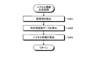
- FIG. 8 is a flowchart showing an overview of the vital information generation processing in step S104 described above.
- the face detection unit 35 detects a face area including the face of the subject included in the RAW image corresponding to the RAW image data acquired by the acquisition unit 31 from the imaging unit 2 (step S401). Specifically, as shown in FIG. 9, the face detection unit 35 applies a wideband image P1 (color image) corresponding to image data of pixel values of the wideband filters C1 to C3 included in the RAW image data. A face region R1 including the face of the subject A1 is detected using a known technique such as pattern matching.
- the generation unit 34 obtains time-series variation data of the ratio between the pixel value of the pixel corresponding to the narrowband filter selected by the selection unit 33 in step S103 and the pixel value of the pixel corresponding to the narrowband filter C5. Calculate (step S402).
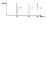
- FIG. 10 is a diagram schematically showing time-series fluctuations in the pixel value of the pixel corresponding to the narrowband filter selected by the selection unit 33 in step S103 described above.
- the pixel value of the pixel corresponding to the narrowband filter C5 It is a figure which shows typically the time series fluctuation
- the horizontal axis represents time
- the vertical axis represents the ratio.
- a polygonal line L3 indicates time-series fluctuations in pixel values obtained by adding all the pixels corresponding to the narrowband filter C5 selected by the selection unit 33.
- the reason why the generation unit 34 uses the time-series fluctuation data is that the generation unit 34 can calculate the oxygen saturation by observing the above-described two wavelengths, but the arterial blood is particularly effective as vital information. It is oxygen saturation.
- a living body has a tissue layer other than blood, an arterial layer, and a venous layer. Among these tissue layers, the thickness of the arterial layer changes in a short time, but the thickness of tissue and vein layers such as skin and meat does not change in a short time. Therefore, the generation unit 34 adds all the pixel values of the pixels corresponding to the narrowband filter selected by the selection unit 33 (see, for example, FIG. 10) and all the pixel values of the pixels corresponding to the narrowband filter C5.
- the generation unit 34 By detecting the fluctuation component of the time series data of the ratio to the added value, the component of only arterial blood is detected. That is, the generation unit 34 has a ratio of a value obtained by adding all the pixel values corresponding to the narrowband filter selected by the selection unit 33 to a value obtained by adding all the pixel values corresponding to the narrowband filter C5. Based on the variation component of the series data, the oxygen saturation of arterial blood is calculated.
- step S403 the generation unit 34 calculates vital information based on the time-series fluctuation data calculated in step S402 described above.
- the generation unit 34 calculates the heart rate that can be calculated from the fluctuation component of the time series data, not just the oxygen saturation, the heart rate at a plurality of locations, and the calculation of the pulse wave propagation velocity that is highly correlated with the blood pressure from the time difference, Emotions and stress by comparison with preset time series data (McDuff, S. Gontarek, R.W.Picard, “Improvements in Remote Cardio-Pulmonary Measurement Using a Five Band Digital Camera”, IEEE Transactions on Biomedical Engineering, (See (2014).) A plurality of vital information may be generated. Further, the generation unit 34 outputs the vital information generated in step S403 to the display unit 4. Thereby, the user can grasp vital information intuitively.
- the image processing unit 3 returns to the main routine of FIG. 4 and ends this processing.
- generation part 34 determined with the near-infrared information corresponding to the light quantity of a non-visible light area
- the vital value of the subject is generated using the pixel value of the pixel in which the narrowband filter C5 is arranged and the pixel value of the pixel in which the narrowband filter C6 is arranged, while the determination unit 32 changes the light amount in the invisible light band.
- the vital value of the subject is determined using the pixel value of the pixel in which the narrowband filter C5 is disposed and the pixel value of the pixel in which the narrowband filter C4 is disposed. Generate information. Thereby, since it is not necessary to provide a light source for irradiating invisible light, the apparatus can be downsized.
- the generation unit 34 generates vital information of the subject based on the RAW image data generated by the image sensor 22, thereby performing outdoor measurement such as digital signage.
- vital information of the subject can be easily generated.
- the generation unit 34 generates vital information of the subject based on the RAW image data generated by the imaging device 22 having the filter array 221 including the narrowband filter C6.
- vital information When vital information is acquired without contact without irradiating non-visible light, it can be acquired with high accuracy.
- the near-infrared component when the near-infrared information is not sufficiently obtained due to the environment at the time of measurement of the subject, the near-infrared component is sufficiently included, for example, like a fluorescent lamp. Even when measurement is performed in an environment with no light source, the generation unit 34 generates vital information of the subject using the pixel value of the pixel corresponding to the narrowband filter C4, and thus obtains highly accurate vital information. be able to.
- the selection unit 33 selects and generates an appropriate narrowband filter according to the environment of the light source at the time of shooting. Since the unit 34 generates vital information using the pixel value of the pixel corresponding to the narrowband filter selected by the selection unit 33, highly accurate vital information can be obtained.
- the face detection unit 35 may detect a facial expression (for example, a smile) of a subject using a known technique.
- the generation unit 34 generates vital information of the subject using the facial expression detected by the face detection unit 35 and the pixel value of the pixel on which the narrowband filter selected by the selection unit 33 is arranged. Also good.
- the imaging apparatus according to the second embodiment is different in configuration from the imaging element 22 according to the first embodiment described above. Specifically, in the image sensor according to the second embodiment, the color filter is formed by only a narrow band filter. Furthermore, the imaging apparatus according to Embodiment 2 differs in the light source information determination process performed by the determination unit. Therefore, in the following, after describing the configuration of the image sensor according to the second embodiment, the light source information determination process performed by the determination unit according to the second embodiment will be described. In the following, the same components as those of the imaging device 1 according to Embodiment 1 described above are denoted by the same reference numerals, and description thereof is omitted.
- FIG. 11 is a diagram schematically showing the configuration of the filter array of the image sensor according to the second embodiment.
- FIG. 12 is a diagram showing an example of spectral sensitivity characteristics of each filter constituting the filter array.
- the horizontal axis indicates the wavelength
- the vertical axis indicates the transmittance.
- the filter array 221a is arranged on the light receiving surface of each pixel constituting the image sensor 22, and is configured using narrowband filters C4 to C6.
- the number of narrowband filters C5 is larger than the number of narrowband filters C4 and C6, and the number of narrowband filters C4 and the number of narrowband filters C6 are the same.
- FIG. 13 is a flowchart showing an outline of the light source information determination process.
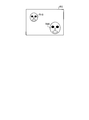
- the face detection unit 35 applies the face of the subject to a RAW image corresponding to the RAW image data acquired by the acquisition unit 31 from the imaging unit 2 using a known technique such as pattern matching. Detects a face region including. Specifically, in the case shown in FIG. 14, the face detection unit 35 detects the face regions R10 and R11 (step S501).
- the determination unit 32 extracts the pixel value of the pixel corresponding to the narrowband filter C6 of each face area detected by the face detection unit 35 (step S502).
- the determination unit 32 calculates the average value Ave_C6 of each face area detected by the face detection unit 35 (step S503).
- the determination unit 32 determines whether or not the average value Ave_C6 of each face area calculated in step S503 is larger than the threshold value Th_ILL (step S504).
- the determination unit 32 determines that the near infrared information is sufficiently included in the face region (step S505).
- the average value Ave_C6 of the face area calculated in step S503 is equal to or less than the threshold Th_ILL (step S504: No)
- the determination unit 32 determines that the near infrared information is not sufficiently included in the face area. (Step S506).
- step S505 or step S506 when the determination by the determination unit 32 is completed for all the face areas detected by the face detection unit 35 (step S507: Yes), the image processing unit 3 goes to the main routine of FIG. Return. On the other hand, when the determination by the determination unit 32 is not completed for all the face areas detected by the face detection unit 35 (step S507: No), the image processing unit 3 returns to step S504.
- the same effects as those of the first embodiment described above are obtained, and the broadband filters C1 to C3 are omitted, so that the cost can be reduced.
- the filter array 221a is composed of only the narrowband filters C4 to C6, vital information can be generated with high accuracy.
- the determination unit 32 determines whether or not the near infrared information is sufficiently included in the face area detected by the face detection unit 35.
- the RAW image It may be determined whether or not near infrared information is sufficiently included for each predetermined region, for example, for each region obtained by dividing the RAW image into four.
- the imaging apparatus according to the third embodiment is different in configuration from the above-described first embodiment. Specifically, the imaging apparatus according to Embodiment 1 described above determines whether or not near-infrared information is sufficiently included based on the RAW image data generated by the imaging unit 2.
- the imaging apparatus according to Embodiment 3 further includes a sensor that detects near-infrared information. For this reason, in the following, after describing the configuration of the imaging apparatus according to the third embodiment, the processing executed by the third embodiment will be described.
- symbol is attached
- FIG. 15 is a block diagram illustrating a functional configuration of the imaging apparatus according to the third embodiment.
- the imaging apparatus 1a illustrated in FIG. 15 further includes a detection unit 5 in addition to the configuration of the imaging apparatus 1 according to Embodiment 1 described above.
- the imaging device 1a includes an image processing unit 3a instead of the image processing unit 3 according to the first embodiment described above.
- the detection unit 5 receives light emitted from the light source, detects the intensity of a predetermined wavelength band, and outputs the detection result to the determination unit 32a.
- the image processing unit 3a includes a determination unit 32a instead of the determination unit 32 in the image processing unit 3 according to Embodiment 1 described above. Based on the detection result input from the detection unit 5, the determination unit 32 a determines whether or not the near-infrared information is sufficiently included in the RAW image data generated by the imaging unit 2.
- the imaging apparatus 1a configured as described above performs the same processing (see FIG. 4) as that of the first embodiment described above.
- the determination unit determines whether near-infrared information is sufficiently included based on the detection result of the detection unit or the RAW image data generated by the imaging unit. For this reason, the configuration of the fourth embodiment will be described below. Note that the same components as those of the imaging device 1a according to the third embodiment described above are denoted by the same reference numerals, and description thereof is omitted.
- FIG. 16 is a block diagram illustrating a functional configuration of the imaging apparatus according to the fourth embodiment.
- An imaging apparatus 1b illustrated in FIG. 16 includes an image processing unit 3b instead of the above-described image processing unit 3a.
- the image processing unit 3b further includes a switching unit 36 in addition to the configuration of the image processing unit 3a described above.
- the switching unit 36 switches the data input to the determination unit 32 b to either RAW image data acquired by the acquisition unit 31 from the imaging unit 2 or the detection result of the detection unit 5. .
- the switching unit 36 drives the switching unit 36 and inputs the detection result of the detection unit 5 to the determination unit 32b.
- the RAW generated by the imaging unit 2 based on the detection result of the detection unit 5 by the determination unit 32 or the RAW image data acquired by the acquisition unit 31 from the imaging unit 2. Since it is determined whether or not the near infrared information is sufficiently included in the image data, the light source information can be determined with high accuracy.
- the generation unit 34 generates vital information using either the pixel value of the pixel corresponding to the narrowband filter C4 or the pixel value of the pixel corresponding to the narrowband filter C6.
- the pixel value of the pixel corresponding to the narrowband filter C4 and the pixel value of the pixel corresponding to the narrowband filter C6 Vital information may be generated using each.
- FIG. 17 is a diagram showing the relationship between the light source spectrum and the sensitivity.
- the horizontal axis indicates the wavelength (nm) and the vertical axis indicates the luminance (W / m 2 ).
- a curve L10 shows the luminance distribution of the fluorescent lamp (part 1)
- a curve L11 shows the luminance distribution of the fluorescent lamp (part 2)
- a curve L12 shows the luminance distribution of the halogen light source.
- the generation unit 34 compares the vital information generated using the pixel value of the pixel corresponding to the narrowband filter C4 and the vital information generated using the pixel value of the pixel corresponding to the narrowband filter C6,
- the vital information with higher reliability is output to the display unit 4.
- the reliability is the stability of vital information between a plurality of frames continuously generated by the imaging unit 2, for example, the rate of change. Thereby, the precision of vital information can be improved more.
- the generation unit 34 generates vital information for the entire image corresponding to the RAW image data using the same narrowband filter. For example, the image is generated for each predetermined region or the face detection unit. Vital information may be generated by selecting a narrowband filter to be used for each face area detected by 35.
- a subject in addition to the imaging device used in the description of the present invention, a subject can be passed through an optical device such as a mobile device or wearable device equipped with an image sensor in a mobile phone or smartphone, a video camera, an endoscope, a surveillance camera, or a microscope.
- an optical device such as a mobile device or wearable device equipped with an image sensor in a mobile phone or smartphone, a video camera, an endoscope, a surveillance camera, or a microscope.
- the present invention can be applied to any device that can image a subject, such as an imaging device for imaging.
- each processing method by the image processing apparatus in the above-described embodiment can be stored as a program that can be executed by a control unit such as a CPU.
- a control unit such as a CPU
- it can be stored and distributed in a storage medium of an external storage device such as a memory card (ROM card, RAM card, etc.), magnetic disk, optical disk (CD-ROM, DVD, etc.), semiconductor memory, or the like.
- a control unit such as a CPU reads the program stored in the storage medium of the external storage device, and the operation described above can be executed by the operation being controlled by the read program.
- the present invention is not limited to the above-described embodiments and modifications as they are, and in the implementation stage, the constituent elements can be modified and embodied without departing from the spirit of the invention.
- Various inventions can be formed by appropriately combining a plurality of constituent elements disclosed in the above-described embodiments. For example, some constituent elements may be deleted from all the constituent elements described in the above-described embodiments and modifications. Furthermore, you may combine suitably the component demonstrated by each embodiment and the modification.
Landscapes
- Engineering & Computer Science (AREA)
- Health & Medical Sciences (AREA)
- Physics & Mathematics (AREA)
- General Physics & Mathematics (AREA)
- Life Sciences & Earth Sciences (AREA)
- Theoretical Computer Science (AREA)
- Multimedia (AREA)
- General Health & Medical Sciences (AREA)
- Medical Informatics (AREA)
- Pathology (AREA)
- Surgery (AREA)
- Veterinary Medicine (AREA)
- Public Health (AREA)
- Animal Behavior & Ethology (AREA)
- Molecular Biology (AREA)
- Biophysics (AREA)
- Heart & Thoracic Surgery (AREA)
- Biomedical Technology (AREA)
- Human Computer Interaction (AREA)
- Oral & Maxillofacial Surgery (AREA)
- Nuclear Medicine, Radiotherapy & Molecular Imaging (AREA)
- Computer Vision & Pattern Recognition (AREA)
- Quality & Reliability (AREA)
- Radiology & Medical Imaging (AREA)
- Measurement Of The Respiration, Hearing Ability, Form, And Blood Characteristics Of Living Organisms (AREA)
- Cardiology (AREA)
- Studio Devices (AREA)
- Optics & Photonics (AREA)
- Measuring Pulse, Heart Rate, Blood Pressure Or Blood Flow (AREA)
- Physiology (AREA)
- Vascular Medicine (AREA)
- Toxicology (AREA)
- Spectroscopy & Molecular Physics (AREA)
Abstract
小型化を図ることができる画像処理装置、撮像装置、画像処理方法およびプログラムを提供する。画像処理部3は、撮像素子22が画像データを生成した際の環境下における非可視光帯域の光量が閾値より大きいか否かを判定する判定部32と、判定部32によって非可視光帯域の光量が閾値以上であると判定された場合、画像において第3狭帯域フィルタが配置された画素の位置に対応する画素値および第2狭帯域フィルタが配置された画素の位置に対応する画素値を用いて被写体のバイタル情報を生成する一方、判定部32によって非可視光帯域の光量が閾値以上でないと判定された場合、画像において第1狭帯域フィルタが配置された画素の位置に対応する画素値および第2狭帯域フィルタが配置された画素の位置に対応する画素値を用いて被写体のバイタル情報を生成する生成部34と、を備える。
Description
本発明は、画像データに基づいて生体等のバイタル情報を生成する画像処理装置、撮像装置、画像処理方法およびプログラムに関する。
従来、医療分野および健康分野において、人間の健康状態を把握するための情報として、心拍数、酸素飽和度および血圧等のバイタル情報を用いて、被写体の健康状態を把握している。例えば、赤色の光および近赤外の光それぞれを照射した生体をイメージセンサによって撮像し、このイメージセンサによって生成された画像データに基づいて、生体の酸素飽和度を算出する技術が知られている(特許文献1参照)。この技術によれば、イメージセンサによって生成された画像データに応じて算出した生体による光の吸収度合いと、この光の吸収度合いの時間変化とに基づいて、生体の酸素飽和度を算出する。
また、被写体の負担を軽減するため、被写体の顔領域に赤色の光および近赤外の光それぞれを照射し、被写体の顔を撮像した動画データの時間変化から被写体のバイタル情報を生成する技術が知られている(特許文献2参照)。
しかしながら、上述した特許文献1,2では、赤色の光および近赤外の光それぞれを照射する光源を必要とするため、装置が大型化するという問題点があった。
本発明は、上記に鑑みてなされたものであって、小型化を図ることができる画像処理装置、撮像装置、画像処理方法およびプログラムを提供することを目的とする。
上述した課題を解決し、目的を達成するために、本発明に係る画像処理装置は、原色の波長帯域より狭い波長帯域を有し、可視光帯域に透過スペクトルの最大値を有する狭帯域光を透過させる第1狭帯域フィルタと、原色の波長帯域より狭い波長帯域を有し、前記狭帯域フィルタと異なる可視光帯域に透過スペクトルの最大値を有する狭帯域光を透過させる第2狭帯域フィルタと、非可視光帯域に透過スペクトルの最大値を有する狭帯域光を透過させる第3狭帯域フィルタと、を用いて所定の配列パターンを形成し、該配列パターンを形成する個々の狭帯域フィルタが複数の画素のいずれかに対応する位置に配置された撮像素子によって生成された画像データを取得する取得部と、前記撮像素子が前記画像データを生成した際の環境下における前記非可視光帯域の光量が閾値より大きいか否かを判定する判定部と、前記判定部によって前記非可視光帯域の光量が前記閾値以上であると判定された場合、前記画像データに対応する画像において前記第3狭帯域フィルタが配置された画素の位置に対応する画素値および前記第2狭帯域フィルタが配置された画素の位置に対応する画素値を用いて被写体のバイタル情報を生成する一方、前記判定部によって前記非可視光帯域の光量が前記閾値以上でないと判定された場合、前記画像データに対応する画像における前記第1狭帯域フィルタが配置された画素の位置に対応する画素値および前記第2狭帯域フィルタが配置された画素の位置に対応する画素値を用いて被写体のバイタル情報を生成する生成部と、を備えたことを特徴とする。
また、本発明に係る画像処理装置は、上記発明において、前記判定部は、前記データに対応する画像における前記第3狭帯域フィルタが配置された画像の位置に対応する画素値に基づいて、前記非可視光帯域の光量が前記閾値より大きいか否かを判定することを特徴とする。
また、本発明に係る画像処理装置は、上記発明において、当該画像処理装置の周囲における前記非可視光帯域の光を検出する検出部をさらに備え、前記判定部は、前記検出部が検出した検出結果に基づいて、前記非可視光帯域の光量が前記閾値より大きいか否かを判定することを特徴とする。
また、本発明に係る画像処理装置は、上記発明において、前記撮像素子は、赤色の波長帯域の光、緑色の波長帯域の光および青色の波長帯域の光のいずれか1つを透過する広帯域フィルタと、前記第1狭帯域フィルタと、前記第2狭帯域フィルタと、前記第3狭帯域フィルタと、を用いて所定の配列パターンを形成し、該配列パターンを形成する個々のフィルタが複数の画素のいずれかに対応する位置に配置されていることを特徴とする。
また、本発明に係る画像処理装置は、上記発明において、前記判定部は、前記画像を複数の領域に分割し、該複数の領域それぞれに対して前記非可視光帯域の成分が前記閾値より大きいか否かを判定し、前記生成部は、前記複数の領域それぞれの前記バイタル情報を生成することを特徴とする。
また、本発明に係る画像処理装置は、上記発明において、前記判定部は、前記画像データに対応する画像の一部である部分領域に対して、前記非可視光帯域の成分が前記閾値より大きいか否かを判定し、前記生成部は、前記部分領域に対して前記バイタル情報を生成することを特徴とする。
また、本発明に係る画像処理装置は、上記発明において、前記画像データに対応する画像に含まれる被写体の顔を検出する顔検出部をさらに備え、前記判定部は、前記顔検出部が検出した前記顔を含む領域に対して、前記非可視光帯域の成分が前記閾値より大きいか否かを判定することを特徴とする。
また、本発明に係る画像処理装置は、上記発明において、前記第1狭帯域フィルタは、緑色の波長帯域の一部に含まれる狭帯域光を透過し、前記第2狭帯域フィルタは、赤色の波長帯域の一部に含まれる狭帯域光を透過し、前記第3狭帯域フィルタは、近赤外の波長帯域の一部に含まれる狭帯域光を透過することを特徴とする。
また、本発明に係る画像処理装置は、上記発明において、前記第1狭帯域フィルタは、波長帯域が490~550nmに含まれる狭帯域光を透過し、前記第2狭帯域フィルタは、波長帯域が620~700nmに含まれる狭帯域光を透過し、前記第3狭帯域フィルタは、波長帯域が800~1000nmに含まれる狭帯域光を透過することを特徴とする。
また、本発明に係る画像処理装置は、上記発明において、前記バイタル情報は、酸素飽和度、心拍および血圧のいずれかであることを特徴とする。
また、本発明に係る撮像装置は、上記の画像処理装置と、前記撮像素子と、を備えたことを特徴とする。
また、本発明に係る画像処理方法は、画像処理装置が実行する画像処理方法であって、原色の波長帯域より狭い波長帯域を有し、可視光帯域に透過スペクトルの最大値を有する狭帯域光を透過させる第1狭帯域フィルタと、原色の波長帯域より狭い波長帯域を有し、前記狭帯域フィルタと異なる可視光帯域に透過スペクトルの最大値を有する狭帯域光を透過させる第2狭帯域フィルタと、非可視光帯域に透過スペクトルの最大値を有する狭帯域光を透過させる第3狭帯域フィルタと、を用いて所定の配列パターンを形成し、該配列パターンを形成する個々の狭帯域フィルタが複数の画素のいずれかに対応する位置に配置された撮像素子によって生成された画像データを取得する取得ステップと、前記撮像素子が前記画像データを生成した際の環境下における前記非可視光帯域の光量が閾値より大きいか否かを判定する判定ステップと、前記判定ステップによって前記非可視光帯域の成分が前記閾値以上であると判定された場合、前記画像データに対応する画像における前記第3狭帯域フィルタが配置された画素の位置に対応する画素値および前記第2狭帯域フィルタが配置された画素の位置に対応する画素値を用いて被写体のバイタル情報を生成する一方、前記判定ステップによって前記非可視光帯域の光量が前記閾値以上でないと判定された場合、前記画像データに対応する画像における前記第1狭帯域フィルタが配置された画素の位置に対応する画素値および前記第2狭帯域フィルタが配置された画素の位置に対応する画素値を用いて被写体のバイタル情報を生成する生成ステップと、を含むことを特徴とする。
また、本発明に係るプログラムは、原色の波長帯域より狭い波長帯域を有し、可視光帯域に透過スペクトルの最大値を有する狭帯域光を透過させる第1狭帯域フィルタと、原色の波長帯域より狭い波長帯域を有し、前記狭帯域フィルタと異なる可視光帯域に透過スペクトルの最大値を有する狭帯域光を透過させる第2狭帯域フィルタと、非可視光帯域に透過スペクトルの最大値を有する狭帯域光を透過させる第3狭帯域フィルタと、を用いて所定の配列パターンを形成し、該配列パターンを形成する個々の狭帯域フィルタが複数の画素のいずれかに対応する位置に配置された撮像素子によって生成された画像データを取得する取得ステップと、前記撮像素子が前記画像データを生成した際の環境下における前記非可視光帯域の光量が閾値より大きいか否かを判定する判定ステップと、前記判定ステップによって前記非可視光帯域の成分が前記閾値以上であると判定された場合、前記画像データに対応する画像における前記第3狭帯域フィルタが配置された画素の位置に対応する画素値および前記第2狭帯域フィルタが配置された画素の位置に対応する画素値を用いて被写体のバイタル情報を生成する一方、前記判定ステップによって前記非可視光帯域の光量が前記閾値以上でないと判定された場合、前記画像データに対応する画像における前記第1狭帯域フィルタが配置された画素の位置に対応する画素値および前記第2狭帯域フィルタが配置された画素の位置に対応する画素値を用いて被写体のバイタル情報を生成する生成ステップと、を画像処理装置に実行させることを特徴とする。
本発明によれば、小型化を図ることができるという効果を奏する。
以下、本発明を実施するための形態を図面とともに詳細に説明する。なお、以下の実施の形態により本発明が限定されるものではない。また、以下の説明において参照する各図は、本発明の内容を理解でき得る程度に形状、大きさ、および位置関係を概略的に示してあるに過ぎない。即ち、本発明は、各図で例示された形状、大きさ、および位置関係のみに限定されるものではない。また、同一の構成には同一の符号を付して説明する。
(実施の形態1)
〔撮像装置の構成〕
図1は、本発明の実施の形態1に係る撮像装置の概略構成を示すブロック図である。図1に示す撮像装置1は、被写体を撮像し、被写体のRAW画像データを生成する撮像部2と、撮像部2が生成したRAW画像データを取得し、取得したRAW画像データに対して所定の処理を行う画像処理部3と、画像処理部3が処理を行ったRAW画像データに対応する画像を表示する表示部4と、を備える。なお、本実施の形態1では、画像処理部3が画像処理装置として機能する。また、本実施の形態1では、撮像部2、画像処理部3および表示部4は、有線または無線によって双方向に通信可能に接続されている。
〔撮像装置の構成〕
図1は、本発明の実施の形態1に係る撮像装置の概略構成を示すブロック図である。図1に示す撮像装置1は、被写体を撮像し、被写体のRAW画像データを生成する撮像部2と、撮像部2が生成したRAW画像データを取得し、取得したRAW画像データに対して所定の処理を行う画像処理部3と、画像処理部3が処理を行ったRAW画像データに対応する画像を表示する表示部4と、を備える。なお、本実施の形態1では、画像処理部3が画像処理装置として機能する。また、本実施の形態1では、撮像部2、画像処理部3および表示部4は、有線または無線によって双方向に通信可能に接続されている。
〔撮像部の構成〕
まず、撮像部2の構成について説明する。
撮像部2は、光学系21と、撮像素子22と、A/D変換部23と、を備える。
まず、撮像部2の構成について説明する。
撮像部2は、光学系21と、撮像素子22と、A/D変換部23と、を備える。
光学系21は、一または複数のレンズ、例えばフォーカスレンズやズームレンズ、絞りおよびシャッタ等を用いて構成され、被写体像を撮像素子22の受光面に結像する。
撮像素子22は、光学系21が受光面に結像した被写体像を受光して光電変換を行うことによって、RAW画像データを生成する。撮像素子22は、格子状に配置された複数の画素がそれぞれ受光した光を光電変換し、電気信号を生成するCMOS(Complementary Metal Oxide Semiconductor)を用いて構成される。また、撮像素子22は、原色の波長帯域の光を透過する複数の広帯域フィルタと、この広帯域フィルタを透過する光の波長帯域より狭い狭帯域の光を透過させる複数の狭帯域フィルタと、を含むフィルタアレイ(CFA)を有する。
図2は、フィルタアレイの構成を模式的に示す図である。図2に示すフィルタアレイ221は、撮像素子22を構成する各画素の受光面に配置され、緑色の光(495~570nm)を透過する広帯域フィルタC1、青色の光(450~495nm)を透過する広帯域フィルタC2と、赤色の光(620~750nm)を透過する広帯域フィルタC3と、緑色の波長帯域の一部に最大値を有し、緑色の波長帯域より狭い光の成分を透過する狭帯域フィルタC4(第1狭帯域フィルタ)と、赤色の波長帯域の一部に最大値を有し、赤色の波長帯域より狭い光の成分を透過する狭帯域フィルタC5(第2狭帯域フィルタ)と、近赤外の光の成分を透過する狭帯域フィルタC6(第3狭帯域フィルタ)と、を用いて構成される。フィルタアレイ221は、広帯域フィルタC1、広帯域フィルタC2および広帯域フィルタC2を合わせた数が狭帯域フィルタC4、狭帯域フィルタC5および狭帯域フィルタC6を合わせた数より多い。具体的には、フィルタアレイ221は、一つの狭帯域フィルタを基準に見た場合、右に3つ画素を進んだ後に、下に1つ進んだ画素の位置に配置される。より具体的には、フィルタアレイ221は、図2の左上端にある狭帯域フィルタC4を基準に見た場合、右に広帯域フィルタC1、広帯域フィルタC3、広帯域フィルタC1の順で進んだ後に、下段の画素に狭帯域フィルタC5が設けられている。
図3は、フィルタアレイ221を構成する各フィルタの分光感度特性の一例を示す図である。なお、図3において、横軸が波長を示し、縦軸が透過率を示す。図3において、曲線LC1が広帯域フィルタC1の透過率を示し、曲線LC2が広帯域フィルタC2の透過率を示し、曲線LC3が広帯域フィルタC3の透過率を示し、曲線LC4が狭帯域フィルタC4の透過率を示し、曲線LC5が狭帯域フィルタC5の透過率を示し、曲線LC6が狭帯域フィルタC6の透過率を示す。
図3に示すように、狭帯域フィルタC4は、緑色の波長帯域の一部に含まれる狭帯域光を透過する。具体的には、狭帯域フィルタC4は、波長帯域が490~550nmに含まれる狭帯域光を透過する。より好ましくは、狭帯域フィルタC4は、520nmの光を透過する。また、狭帯域フィルタC5は、赤色の波長帯域の一部に含まれる狭帯域光を透過する。具体的には、狭帯域フィルタC5は、波長帯域が620~700nmに含まれる狭帯域光を透過する。より好ましくは、狭帯域フィルタC5は、660nmの光を透過する。さらに、狭帯域フィルタC6は、近赤外の波長帯域の一部に含まれる狭帯域光を透過する。具体的には、狭帯域フィルタC6は、波長帯域が800~1000nmに含まれる狭帯域光を透過する。より好ましくは、狭帯域フィルタC6は、940nmの光を透過する。なお、本実施の形態1では、狭帯域フィルタC4が透過する透過スペクトルを520nm、狭帯域フィルタC5が透過する透過スペクトルを660nm、狭帯域フィルタC6が透過する透過スペクトルを940nmとして説明する。
図1に戻り、撮像部2の構成の説明を続ける。
A/D変換部23は、撮像素子22が生成したアナログのRAW画像データをデジタルに変換する。
A/D変換部23は、撮像素子22が生成したアナログのRAW画像データをデジタルに変換する。
〔画像処理部の構成〕
次に、画像処理部3の構成について説明する。
画像処理部3は、取得部31と、判定部32と、選択部33と、生成部34と、顔検出部35と、を有する。
次に、画像処理部3の構成について説明する。
画像処理部3は、取得部31と、判定部32と、選択部33と、生成部34と、顔検出部35と、を有する。
取得部31は、撮像部2から撮像素子22によって生成されたRAW画像データを取得し、取得したRAW画像データを判定部32、生成部34および顔検出部35それぞれに出力する。
判定部32は、撮像素子22が画像データを生成した際の環境下における非可視光帯域の光量が閾値より大きいか否かを判定する。具体的には、判定部32は、取得部31が撮像部2から取得したRAW画像データに近赤外情報が含まれているか否かを判定する。例えば、判定部32は、取得部31が撮像部2から取得したRAW画像データに対応する画像において狭帯域フィルタC6が配置された画素の位置に対応する対応する画素の画素値を抽出後、この抽出した狭帯域フィルタC6に対応する画素の画素値の平均値を算出し、算出した平均値が閾値より大きいか否かを判定することによって、撮像素子22が画像データを生成した際の環境下における非可視光帯域の光量(近赤外情報)が閾値より大きいか否かを判定する。
選択部33は、判定部32の判定結果に基づいて、生成部34がバイタル情報を生成する際に用いる狭帯域フィルタを選択する。具体的には、選択部33は、判定部32がRAW画像データに近赤外情報が十分に含まれていると判定した場合、生成部34がバイタル情報生成に用いる狭帯域フィルタ(バンド)として狭帯域フィルタC6を選択する一方、判定部32がRAW画像データに近赤外情報が十分に含まれていないと判定した場合、生成部34がバイタル情報生成に用いる狭帯域フィルタとして狭帯域フィルタC4を選択する。
生成部34は、選択部33の選択結果、取得部31が撮像部2から取得したRAW画像データおよび顔検出部35の検出結果に基づいて、RAW画像データに対応するRAW画像に含まれる被写体の顔を含む顔領域のバイタル情報を生成する。ここで、バイタル情報とは、酸素飽和度、心拍および血圧のいずれかである。具体的には、生成部34は、判定部32によって非可視光帯域の成分が閾値以上であると判定された場合、撮像素子22によって生成されたRAW画像データに対応する画像において狭帯域フィルタC4が配置された画素の位置に対応する画素値および狭帯域フィルタC5が配置された画素の位置に対応する画素値を用いて被写体のバイタル情報を生成する一方、判定部32によって非可視光帯域の光量が閾値以上でないと判定された場合、撮像素子22によって生成された画像データに対応する画像における狭帯域フィルタC4が配置された画素の位置に対応する画素値および狭帯域フィルタC5が配置された画素の位置に対応する画素値を用いて被写体のバイタル情報を生成する。
顔検出部35は、取得部31から入力されたRAW画像データに対応する画像に含まれる被写体の顔を含む領域を、周知のパターンマッチング等を用いて検出し、この検出結果を生成部34へ出力する。
〔表示部の構成〕
次に、表示部4の構成について説明する。
表示部4は、画像処理部3が処理を施した画像データに対応する画像を表示する。表示部4は、有機EL(Electro Luminescence)や液晶等の表示パネルや表示駆動ドライバ等を用いて構成される。
次に、表示部4の構成について説明する。
表示部4は、画像処理部3が処理を施した画像データに対応する画像を表示する。表示部4は、有機EL(Electro Luminescence)や液晶等の表示パネルや表示駆動ドライバ等を用いて構成される。
このように構成された撮像装置1は、撮像部2で被写体を撮像して被写体のRAW画像データを生成し、画像処理部3が撮像部2によって生成されたRAW画像データを用いて被写体のバイタル情報を生成し、表示部4が画像処理部3によって生成された被写体のバイタル情報を表示する。これにより、ユーザは、バイタル情報を直感的に把握することができる。
〔画像処理部の処理〕
次に、画像処理部3が実行する処理について説明する。図4は、画像処理部3が実行する処理の概要を示すフローチャートである。
次に、画像処理部3が実行する処理について説明する。図4は、画像処理部3が実行する処理の概要を示すフローチャートである。
図4に示すように、まず、取得部31は、撮像部2からRAW画像データを取得する(ステップS101)。
続いて、判定部32は、取得部31が撮像部2から取得したRAW画像データに基づいて、近赤外情報が十分に含まれているか否かを判定する光源情報判定処理を実行する(ステップS102)。
〔光源情報判定処理の概要〕
図5は、上述したステップS102の光源情報判定処理の概要を示すフローチャートである。
図5は、上述したステップS102の光源情報判定処理の概要を示すフローチャートである。
図5に示すように、判定部32は、取得部31が撮像部2から取得したRAW画像データから狭帯域フィルタC6に対応する画素の画素値を抽出し(ステップS201)、判定部32は、RAW画像データに対応する画像全体の平均値Ave_C6を算出する(ステップS202)。ここで、平均値Ave_C6とは、RAW画像データから狭帯域フィルタC6に対応する各画素の画素値を加算して平均した値である。
その後、判定部32は、ステップS202で算出した平均値Ave_C6が閾値Th_ILLより大きいか否かを判定する(ステップS203)。ここで、閾値Th_ILLとは、予め実験等によって算出された値である。平均値Ave_C6が閾値Th_ILLより大きい場合(ステップS203:Yes)、判定部32は、RAW画像データに近赤外情報が十分に含まれていると判定する(ステップS204)。ステップS204の後、画像処理部3は、図4のメインルーチンへ戻る。
ステップS203において、平均値Ave_C6が閾値Th_ILL以下の場合(ステップS203:No)、判定部32は、RAW画像データに近赤外情報が十分に含まれていないと判定する(ステップS205)。ステップS205の後、画像処理部3は、図4のメインルーチンへ戻る。
図4に戻り、ステップS103以降の説明を続ける。
ステップS103において、選択部33は、判定部32の判定結果に基づいて、バイタル情報を生成するためのフィルタを選択するバイタル情報生成用フィルタ選択処理を実行する。
ステップS103において、選択部33は、判定部32の判定結果に基づいて、バイタル情報を生成するためのフィルタを選択するバイタル情報生成用フィルタ選択処理を実行する。
〔バイタル情報生成用フィルタ選択処理の概要〕
図6は、上述したステップS103のバイタル情報生成用フィルタ選択処理の概要を示すフローチャートである。
図6は、上述したステップS103のバイタル情報生成用フィルタ選択処理の概要を示すフローチャートである。
図6に示すように、選択部33は、判定部32がRAW画像データに近赤外情報が十分に含まれていると判定したと場合(ステップS301:Yes)、生成部34がバイタル情報生成に用いる狭帯域フィルタとして狭帯域フィルタC6を選択する(ステップS302)。ステップS302の後、画像処理部3は、図4のメインルーチンへ戻る。
ステップS301において、選択部33は、判定部32がRAW画像データに近赤外情報が十分に含まれていない判定した場合(ステップS301:No)、生成部34がバイタル情報生成に用いる狭帯域フィルタとして狭帯域フィルタC4を選択する(ステップS303)。ステップS303の後、画像処理部3は、図4のメインルーチンへ戻る。
ここで、バイタル情報生成に用いるフィルタの波長帯域について詳細に説明する。図7は、ヘモグロビンの吸収特性を示す図である。図7において、横軸が波長(nm)を示し、縦軸がモル吸収係数(cm-1/m)を示す。また、図7において、曲線L1が還元ヘモグロビンのモル吸収係数を示し、曲線L2が酸化ヘモグロビンのモル吸収係数を示す。また、図7において、直線B1が狭帯域フィルタC4に対応する波長帯域を示し、直線B2が狭帯域フィルタC5に対応する波長帯域を示し、直線B3が狭帯域フィルタC6に対応する波長帯域を示す。
血液中のヘモグロビンには、酸素と結合していない還元ヘモグロビン(Hb)および酸素と結合している酸化ヘモグロビン(HbO2)の2種類がある。本実施の形態1で用いるバイタル情報の1つには、血液中の全てのヘモグロビンにおける酸化ヘモグロビンの割合を示す酸素飽和度(SPO2)がある。この酸素飽和度は、以下の式(1)によって算出される。
SPO2=(C((HbO2)/(C(HbO2)+(C(Hb))))×100・・・(1)
ここで、C((HbO2)は、酸化ヘモグロビンの濃度を示し、(C(Hb))は、還元ヘモグロビンの濃度を示す。
SPO2=(C((HbO2)/(C(HbO2)+(C(Hb))))×100・・・(1)
ここで、C((HbO2)は、酸化ヘモグロビンの濃度を示し、(C(Hb))は、還元ヘモグロビンの濃度を示す。
本実施の形態1においては、酸化ヘモグロビンおよび還元ヘモグロビンそれぞれの波長毎の吸収特性の違いを利用する。即ち、図7に示すように、本実施の形態1では、酸化ヘモグロビンおよび還元ヘモグロビンそれぞれの吸収特性の差が大きい波長660nmと、酸化ヘモグロビンおよび還元ヘモグロビンそれぞれの吸収特性の差が小さい波長940nmまたは波長520nmとを用いることによって、後述する生成部34がバイタル情報として酸素飽和度を算出する(なお、酸素飽和度の原理的な方法は、特許文献1を参照。また、非接触による酸素飽和度の方法(画像データを用いて間接的に推定する方法)は、Lingqin Kong et al. ,“Non-contact detection of oxygen saturation based on visible light imaging device using ambient light”, Optics Express, Vol. 21, Issue 15, pp. 17464- 17471 (2013)を参照)。このため、選択部33は、判定部32がRAW画像データに近赤外情報が十分に含まれていると判定している場合、生成部34がバイタル情報生成に用いるフィルタとして狭帯域フィルタC6を選択する一方、判定部32がRAW画像データに近赤外情報が十分に含まれていないと判定した場合、生成部34がバイタル情報生成に用いるフィルタとして狭帯域フィルタC4を選択する。
図4に戻り、ステップS104以降の説明を続ける。
ステップS104において、生成部34は、選択部33の選択結果と取得部31が撮像部2から取得したRAW画像データとに基づいて、RAW画像データに対応するRAW画像に含まれる被写体の顔を含む顔領域のバイタル情報を生成するバイタル情報生成処理を実行する。
ステップS104において、生成部34は、選択部33の選択結果と取得部31が撮像部2から取得したRAW画像データとに基づいて、RAW画像データに対応するRAW画像に含まれる被写体の顔を含む顔領域のバイタル情報を生成するバイタル情報生成処理を実行する。
〔バイタル情報生成処理の概要〕
図8は、上述したステップS104のバイタル情報生成処理の概要を示すフローチャートである。
図8は、上述したステップS104のバイタル情報生成処理の概要を示すフローチャートである。
図8に示すように、顔検出部35は、取得部31が撮像部2から取得したRAW画像データに対応するRAW画像に含まれる被写体の顔を含む顔領域を検出する(ステップS401)。具体的には、図9に示すように、顔検出部35は、RAW画像データに含まれる広帯域フィルタC1~C3それぞれの画素値の画像データに対応する広帯域画像P1(カラー画像)に対して、周知のパターンマッチング等の技術を用いて被写体A1の顔を含む顔領域R1を検出する。
続いて、生成部34は、上述したステップS103で選択部33が選択した狭帯域フィルタに対応する画素の画素値と狭帯域フィルタC5に対応する画素の画素値との比率の時系列変動データを算出する(ステップS402)。
図10は、上述したステップS103で選択部33が選択した狭帯域フィルタに対応する画素の画素値の時系列変動を模式的に示す図であり、例えば狭帯域フィルタC5に対応する画素の画素値の時系列変動を模式的に示す図である。図10において、横軸が時間を示し、縦軸が比率を示す。また、折れ線L3は、選択部33が選択した狭帯域フィルタC5に対応する画素を全て加算した画素値の時系列変動を示す。
ここで、生成部34が時系列変動データを用いる理由は、上述した2つの波長を観察することによって生成部34が酸素飽和度を算出することができるが、バイタル情報として特に有効なのが動脈血の酸素飽和度である。生体には、血液以外の組織層、動脈層および静脈層が存在する。これらの組織層のうち動脈層は、短時間で厚みが変化するが、皮膚や肉等の組織や静脈層は、短時間で厚みが変化しない。このため、生成部34は、選択部33が選択した狭帯域フィルタに対応する画素の画素値を全て加算した値(例えば図10を参照)と狭帯域フィルタC5に対応する画素の画素値を全て加算した値との比率の時系列データの変動成分を検出することによって、動脈血のみの成分を検出する。即ち、生成部34は、選択部33が選択した狭帯域フィルタに対応する画素の画素値を全て加算した値と狭帯域フィルタC5に対応する画素の画素値を全て加算した値との比率の時系列データの変動成分に基づいて、動脈血の酸素飽和度を算出する。
ステップS403において、生成部34は、上述したステップS402で算出した時系列変動データに基づいて、バイタル情報を算出する。なお、生成部34は、酸素飽和度に限らず、時系列データの変動成分から算出できる心拍数、複数箇所の心拍数を算出し、その時間差から血圧と相関の高い脈波伝播速度の算出、および予め設定された時系列データとの比較による感情やストレス(McDuff, S. Gontarek, R. W. Picard, “Improvements in Remote Cardio-Pulmonary Measurement Using a Five Band Digital Camera”, IEEE Transactions on Biomedical Engineering, (2014)を参照。)等を含む複数のバイタル情報を生成してもよい。また、生成部34は、ステップS403で生成したバイタル情報を表示部4へ出力する。これにより、ユーザは、バイタル情報を直感的に把握することができる。ステップS403の後、画像処理部3は、図4のメインルーチンへ戻り、本処理を終了する。
以上説明した本発明の実施の形態1によれば、生成部34が判定部32によってRAW画像データに非可視光領域の光量に対応する近赤外情報が十分に含まれていると判定された場合、狭帯域フィルタC5が配置された画素の画素値および狭帯域フィルタC6が配置された画素の画素値を用いて被写体のバイタル情報を生成する一方、判定部32によって非可視光帯域の光量に対応する近赤外情報が十分に含まれていないと判定された場合、狭帯域フィルタC5が配置された画素の画素値および狭帯域フィルタC4が配置された画素の画素値を用いて被写体のバイタル情報を生成する。これにより、非可視光を照射する光源を設けなくてもよいので、装置の小型化を図ることができる。
また、本発明の実施の形態1によれば、生成部34が撮像素子22によって生成されたRAW画像データに基づいて、被写体のバイタル情報を生成することによって、デジタルサイネージのような屋外での計測および不特定多数の被写体を対象とするような利用シーンにおいて特定の波長帯域の光を正確に照射する必要がないので、簡易に被写体のバイタル情報を生成することができる。
さらに、本発明の実施の形態1によれば、生成部34が狭帯域フィルタC6を含むフィルタアレイ221を有する撮像素子22によって生成されたRAW画像データに基づいて、被写体のバイタル情報を生成するので、非可視光を照射することなく、非接触でバイタル情報を取得する場合に高精度で取得することができる。
さらにまた、本発明の実施の形態1によれば、被写体の計測時の環境下によって近赤外情報が十分に得られない場合、例えば蛍光灯のように近赤外成分が十分に含まれていない光源の環境下で計測を行った場合であっても、生成部34が狭帯域フィルタC4に対応する画素の画素値を用いて被写体のバイタル情報を生成するので、高精度なバイタル情報を得ることができる。
また、本発明の実施の形態1によれば、非可視光を照射しない場合であっても、撮影時の光源の環境下に応じて、選択部33が適切な狭帯域フィルタを選択し、生成部34が選択部33によって選択された狭帯域フィルタに対応する画素の画素値を用いてバイタル情報を生成するので、高精度なバイタル情報を得ることができる。
なお、本発明の実施の形態1では、顔検出部35が周知技術を用いて被写体の顔の表情(例えば笑顔や)を検出してもよい。この場合、生成部34は、顔検出部35が検出した顔の表情と選択部33によって選択された狭帯域フィルタが配置された画素の画素値とを用いて、被写体のバイタル情報を生成してもよい。
(実施の形態2)
次に、本発明の実施の形態2について説明する。本実施の形態2に係る撮像装置は、上述した実施の形態1に係る撮像素子22と構成が異なる。具体的には、本実施の形態2に係る撮像素子は、カラーフィルタが狭帯域フィルタのみによって形成されている。さらに、本実施の形態2に係る撮像装置は、判定部が行う光源情報判定処理が異なる。このため、以下においては、本実施の形態2に係る撮像素子の構成を説明後、本実施の形態2に係る判定部が行う光源情報判定処理について説明する。なお、以下において、上述した実施の形態1に係る撮像装置1と同一の構成には同一の符号を付して説明を省略する。
次に、本発明の実施の形態2について説明する。本実施の形態2に係る撮像装置は、上述した実施の形態1に係る撮像素子22と構成が異なる。具体的には、本実施の形態2に係る撮像素子は、カラーフィルタが狭帯域フィルタのみによって形成されている。さらに、本実施の形態2に係る撮像装置は、判定部が行う光源情報判定処理が異なる。このため、以下においては、本実施の形態2に係る撮像素子の構成を説明後、本実施の形態2に係る判定部が行う光源情報判定処理について説明する。なお、以下において、上述した実施の形態1に係る撮像装置1と同一の構成には同一の符号を付して説明を省略する。
図11は、本実施の形態2に係る撮像素子のフィルタアレイの構成を模式的に示す図である。図12は、フィルタアレイを構成する各フィルタの分光感度特性の一例を示す図である。なお、図12において、横軸が波長を示し、縦軸が透過率を示す。
図11および図12に示すように、フィルタアレイ221aは、撮像素子22を構成する各画素の受光面に配置され、狭帯域フィルタC4~C6を用いて構成される。フィルタアレイ221aは、狭帯域フィルタC5の数が狭帯域フィルタC4および狭帯域フィルタC6の数より多く、狭帯域フィルタC4の数と狭帯域フィルタC6の数とが同じである。
〔光源情報判定処理の概要〕
次に、画像処理部3が実行する光源情報判定処理について説明する。図13は、光源情報判定処理の概要を示すフローチャートである。
次に、画像処理部3が実行する光源情報判定処理について説明する。図13は、光源情報判定処理の概要を示すフローチャートである。
図13に示すように、まず、顔検出部35は、取得部31が撮像部2から取得したRAW画像データに対応するRAW画像に対して、周知のパターンマッチング等の技術を用いて被写体の顔が含まれる顔領域を検出する。具体的には、図14に示す場合、顔検出部35は、顔領域R10,R11を検出する(ステップS501)。
続いて、判定部32は、顔検出部35によって検出された各顔領域の狭帯域フィルタC6に対応する画素の画素値を抽出する(ステップS502)。
その後、判定部32は、顔検出部35によって検出された各顔領域の平均値Ave_C6を算出する(ステップS503)。
続いて、判定部32は、ステップS503で算出した各顔領域の平均値Ave_C6が閾値Th_ILLより大きいか否かを判定する(ステップS504)。平均値Ave_C6が閾値Th_ILLより大きい場合(ステップS504:Yes)、判定部32は、顔領域に近赤外情報が十分に含まれていると判定する(ステップS505)。これに対して、ステップS503で算出した顔領域の平均値Ave_C6が閾値Th_ILL以下の場合(ステップS504:No)、判定部32は、顔領域に近赤外情報が十分に含まれていないと判定する(ステップS506)。
ステップS505またはステップS506の後、顔検出部35が検出した全ての顔領域に対して判定部32による判定が終了した場合(ステップS507:Yes)、画像処理部3は、図4のメインルーチンへ戻る。これに対して、顔検出部35が検出した全ての顔領域に対して判定部32による判定が終了していない場合(ステップS507:No)、画像処理部3は、ステップS504へ戻る。
以上説明した本発明の実施の形態2によれば、上述した実施の形態1と同様の効果を有するうえ、広帯域フィルタC1~C3を省略しているので、安価にすることができる。
さらに、本発明の実施の形態2によれば、フィルタアレイ221aを狭帯域フィルタC4~C6のみで構成しているので、バイタル情報を高精度に生成することができる。
なお、本発明の実施の形態2では、判定部32が顔検出部35によって検出された顔領域に対して近赤外情報が十分に含まれているか否かを判定していたが、RAW画像を所定の領域毎、例えばRAW画像を4分割した領域毎に近赤外情報が十分に含まれているか否かの判定を行ってもよい。
(実施の形態3)
次に、本発明の実施の形態3について説明する。本実施の形態3に係る撮像装置は、上述した実施の形態1と構成が異なる。具体的には、上述した実施の形態1に係る撮像装置は、撮像部2が生成したRAW画像データに基づいて、近赤外の情報が十分に含まれているか否かを判定したが、本実施の形態3に係る撮像装置は、近赤外の情報を検出するセンサをさらに備える。このため、以下においては、本実施の形態3に係る撮像装置の構成を説明後、本実施の形態3が実行する処理について説明する。なお、上述した実施の形態1に係る撮像装置1と同一の構成には同一の符号を付して説明を省略する。
次に、本発明の実施の形態3について説明する。本実施の形態3に係る撮像装置は、上述した実施の形態1と構成が異なる。具体的には、上述した実施の形態1に係る撮像装置は、撮像部2が生成したRAW画像データに基づいて、近赤外の情報が十分に含まれているか否かを判定したが、本実施の形態3に係る撮像装置は、近赤外の情報を検出するセンサをさらに備える。このため、以下においては、本実施の形態3に係る撮像装置の構成を説明後、本実施の形態3が実行する処理について説明する。なお、上述した実施の形態1に係る撮像装置1と同一の構成には同一の符号を付して説明を省略する。
〔撮像装置の構成〕
図15は、本実施の形態3に係る撮像装置の機能構成を示すブロック図である。図15に示す撮像装置1aは、上述した実施の形態1に係る撮像装置1の構成に加えて、検出部5をさらに備える。また、撮像装置1aは、上述した実施の形態1に係る画像処理部3に換えて、画像処理部3aを備える。
図15は、本実施の形態3に係る撮像装置の機能構成を示すブロック図である。図15に示す撮像装置1aは、上述した実施の形態1に係る撮像装置1の構成に加えて、検出部5をさらに備える。また、撮像装置1aは、上述した実施の形態1に係る画像処理部3に換えて、画像処理部3aを備える。
検出部5は、光源から照射された光を受光して所定の波長帯域の強度を検出し、この検出結果を判定部32aへ出力する。
画像処理部3aは、上述した実施の形態1に係る画像処理部3における判定部32に換えて、判定部32aを有する。判定部32aは、検出部5から入力された検出結果に基づいて、撮像部2が生成したRAW画像データに近赤外情報が十分に含まれているか否かを判定する。
このように構成された撮像装置1aは、上述した実施の形態1と同様の処理(図4を参照)を実行する。
以上説明した本発明の実施の形態3によれば、判定部32aが検出部5の検出結果に基づいて、撮像部2によって生成されたRAW画像データに近赤外情報が十分に含まれているか否かを判定するので、高精度に光源情報を判定することができる。
(実施の形態4)
次に、本発明の実施の形態4について説明する。本実施の形態4は、上述した実施の形態3と構成が異なる。具体的には、本実施の形態4は、判定部が検出部の検出結果または撮像部が生成したRAW画像データに基づいて、近赤外情報が十分に含まれているか否かを判定する。このため、以下においては、本実施の形態4の構成について説明する。なお、上述した実施の形態3に係る撮像装置1aと同一の構成には同一の符号を付して説明を省略する。
次に、本発明の実施の形態4について説明する。本実施の形態4は、上述した実施の形態3と構成が異なる。具体的には、本実施の形態4は、判定部が検出部の検出結果または撮像部が生成したRAW画像データに基づいて、近赤外情報が十分に含まれているか否かを判定する。このため、以下においては、本実施の形態4の構成について説明する。なお、上述した実施の形態3に係る撮像装置1aと同一の構成には同一の符号を付して説明を省略する。
図16は、本実施の形態4に係る撮像装置の機能構成を示すブロック図である。図16に示す撮像装置1bは、上述した画像処理部3aに換えて、画像処理部3bを有する。画像処理部3bは、上述した画像処理部3aの構成に加えて、切替部36をさらに有する。
切替部36は、生成部34の制御のもと、判定部32bに入力されるデータを、取得部31が撮像部2から取得したRAW画像データおよび検出部5の検出結果のどちらか一方に切り替える。例えば、切替部36は、判定部32bがRAW画像データに近赤外情報が十分に含まれていないと判定した場合、切替部36を駆動させて検出部5の検出結果を判定部32bに入力させる。
以上説明した本発明の実施の形態4によれば、判定部32bが検出部5の検出結果または取得部31が撮像部2から取得したRAW画像データに基づいて、撮像部2によって生成されたRAW画像データに近赤外情報が十分に含まれているか否かを判定するので、高精度に光源情報を判定することができる。
(その他の実施の形態)
上述した実施の形態1~4では、生成部34が狭帯域フィルタC4に対応する画素の画素値および狭帯域フィルタC6に対応する画素の画素値のいずれか一方を用いてバイタル情報を生成していたが、例えばハロゲン光源のように可視光波長帯域および近赤外波長帯域に感度を有する光源の場合、狭帯域フィルタC4に対応する画素の画素値および狭帯域フィルタC6に対応する画素の画素値それぞれを用いてバイタル情報を生成してもよい。
上述した実施の形態1~4では、生成部34が狭帯域フィルタC4に対応する画素の画素値および狭帯域フィルタC6に対応する画素の画素値のいずれか一方を用いてバイタル情報を生成していたが、例えばハロゲン光源のように可視光波長帯域および近赤外波長帯域に感度を有する光源の場合、狭帯域フィルタC4に対応する画素の画素値および狭帯域フィルタC6に対応する画素の画素値それぞれを用いてバイタル情報を生成してもよい。
図17は、光源スペクトルと感度との関係を示す図である。図17において、横軸が波長(nm)を示し、縦軸が輝度(W/m2)を示す。また、図17において、曲線L10が蛍光灯(その1)の輝度分布を示し、曲線L11が蛍光灯(その2)の輝度分布を示し、曲線L12がハロゲン光源の輝度分布を示す。
図17の曲線L12に示すように、ハロゲン光源は、可視光波長帯域および近赤外波長帯域に感度を有する。このため、生成部34は、狭帯域フィルタC4に対応する画素の画素値を用いて生成したバイタル情報と狭帯域フィルタC6に対応する画素の画素値を用いて生成したバイタル情報とを比較し、信頼度が高い方のバイタル情報を表示部4に出力する。ここで、信頼度とは、撮像部2が連続的に生成した複数のフレーム間でのバイタル情報の安定性、例えば変化率である。これにより、バイタル情報の精度をより向上させることができる。
また、本発明では、生成部34がRAW画像データに対応する画像全体に対して、同一の狭帯域フィルタを用いてバイタル情報を生成していたが、例えば画像を所定の領域毎または顔検出部35が検出した顔領域毎に用いる狭帯域フィルタを選択してバイタル情報を生成してもよい。
本発明は、上述した実施の形態に限定されるものではなく、本発明の要旨の範囲内で種々の変形や応用が可能なことは勿論である。例えば、本発明の説明に用いた撮像装置以外にも、携帯電話やスマートフォンにおける撮像素子を備えた携帯機器やウエアラブル機器、ビデオカメラ、内視鏡、監視カメラ、顕微鏡のような光学機器を通して被写体を撮影する撮像装置等、被写体を撮像可能ないずれの機器にも適用できる。
また、本明細書において、前述の各動作フローチャートの説明において、便宜上「まず」、「次に」、「続いて」、「その後」等を用いて動作を説明しているが、この順で動作を実施することが必須であることを意味するものではない。
また、上述した実施の形態における画像処理装置による各処理の手法、即ち、各フローチャートに示す処理は、いずれもCPU等の制御部に実行させることができるプログラムとして記憶させておくこともできる。この他、メモリカード(ROMカード、RAMカード等)、磁気ディスク、光ディスク(CD-ROM、DVD等)、半導体メモリ等の外部記憶装置の記憶媒体に格納して配布することができる。そして、CPU等の制御部は、この外部記憶装置の記憶媒体に記憶されたプログラムを読み込み、この読み込んだプログラムによって動作が制御されることにより、上述した処理を実行することができる。
また、本発明は、上述した実施の形態および変形例そのままに限定されるものではなく、実施段階では、発明の要旨を逸脱しない範囲内で構成要素を変形して具体化することができる。また、上述した実施の形態に開示されている複数の構成要素を適宜組み合わせることによって、種々の発明を形成することができる。例えば、上述した実施の形態および変形例に記載した全構成要素からいくつかの構成要素を削除してもよい。さらに、各実施の形態および変形例で説明した構成要素を適宜組み合わせてもよい。
また、明細書または図面において、少なくとも一度、より広義または同義な異なる用語とともに記載された用語は、明細書または図面のいかなる箇所においても、その異なる用語に置き換えることができる。このように、発明の主旨を逸脱しない範囲内において種々の変形や応用が可能である。
1,1a,1b 撮像装置
2 撮像部
3,3a,3b 画像処理部
4 表示部
5 検出部
21 光学系
22 撮像素子
23 A/D変換部
31 取得部
32,32a,32b 判定部
33 選択部
34 生成部
35 顔検出部
36 切替部
221,221a フィルタアレイ
C1,C2,C3 広帯域フィルタ
C4,C5,C6 狭帯域フィルタ
2 撮像部
3,3a,3b 画像処理部
4 表示部
5 検出部
21 光学系
22 撮像素子
23 A/D変換部
31 取得部
32,32a,32b 判定部
33 選択部
34 生成部
35 顔検出部
36 切替部
221,221a フィルタアレイ
C1,C2,C3 広帯域フィルタ
C4,C5,C6 狭帯域フィルタ
Claims (13)
- 原色の波長帯域より狭い波長帯域を有し、可視光帯域に透過スペクトルの最大値を有する狭帯域光を透過させる第1狭帯域フィルタと、原色の波長帯域より狭い波長帯域を有し、前記狭帯域フィルタと異なる可視光帯域に透過スペクトルの最大値を有する狭帯域光を透過させる第2狭帯域フィルタと、非可視光帯域に透過スペクトルの最大値を有する狭帯域光を透過させる第3狭帯域フィルタと、を用いて所定の配列パターンを形成し、該配列パターンを形成する個々の狭帯域フィルタが複数の画素のいずれかに対応する位置に配置された撮像素子によって生成された画像データを取得する取得部と、
前記撮像素子が前記画像データを生成した際の環境下における前記非可視光帯域の光量が閾値より大きいか否かを判定する判定部と、
前記判定部によって前記非可視光帯域の光量が前記閾値以上であると判定された場合、前記画像データに対応する画像において前記第3狭帯域フィルタが配置された画素の位置に対応する画素値および前記第2狭帯域フィルタが配置された画素の位置に対応する画素値を用いて被写体のバイタル情報を生成する一方、前記判定部によって前記非可視光帯域の光量が前記閾値以上でないと判定された場合、前記画像データに対応する画像における前記第1狭帯域フィルタが配置された画素の位置に対応する画素値および前記第2狭帯域フィルタが配置された画素の位置に対応する画素値を用いて被写体のバイタル情報を生成する生成部と、
を備えたことを特徴とする画像処理装置。 - 前記判定部は、前記データに対応する画像における前記第3狭帯域フィルタが配置された画像の位置に対応する画素値に基づいて、前記非可視光帯域の光量が前記閾値より大きいか否かを判定することを特徴とする請求項1に記載の画像処理装置。
- 当該画像処理装置の周囲における前記非可視光帯域の光を検出する検出部をさらに備え、
前記判定部は、前記検出部が検出した検出結果に基づいて、前記非可視光帯域の光量が前記閾値より大きいか否かを判定することを特徴とする請求項1に記載の画像処理装置。 - 前記撮像素子は、赤色の波長帯域の光、緑色の波長帯域の光および青色の波長帯域の光のいずれか1つを透過する広帯域フィルタと、前記第1狭帯域フィルタと、前記第2狭帯域フィルタと、前記第3狭帯域フィルタと、を用いて所定の配列パターンを形成し、該配列パターンを形成する個々のフィルタが複数の画素のいずれかに対応する位置に配置されていることを特徴とする請求項1~3のいずれか一つに記載の画像処理装置。
- 前記判定部は、前記画像データに対応する画像を複数の領域に分割し、該複数の領域それぞれに対して前記非可視光帯域の成分が前記閾値より大きいか否かを判定し、
前記生成部は、前記複数の領域それぞれの前記バイタル情報を生成することを特徴とする請求項1~4のいずれか一つに記載の画像処理装置。 - 前記判定部は、前記画像データに対応する画像の一部である部分領域に対して、前記非可視光帯域の成分が前記閾値より大きいか否かを判定し、
前記生成部は、前記部分領域に対して前記バイタル情報を生成することを特徴とする請求項1~4のいずれか一つに記載の画像処理装置。 - 前記画像データに対応する画像に含まれる被写体の顔を検出する顔検出部をさらに備え、
前記判定部は、前記顔検出部が検出した前記顔を含む領域に対して、前記非可視光帯域の成分が前記閾値より大きいか否かを判定することを特徴とする請求項6に記載の画像処理装置。 - 前記第1狭帯域フィルタは、緑色の波長帯域の一部に含まれる狭帯域光を透過し、
前記第2狭帯域フィルタは、赤色の波長帯域の一部に含まれる狭帯域光を透過し、
前記第3狭帯域フィルタは、近赤外の波長帯域の一部に含まれる狭帯域光を透過することを特徴とする請求項1~7のいずれか一つに記載の画像処理装置。 - 前記第1狭帯域フィルタは、波長帯域が490~550nmに含まれる狭帯域光を透過し、
前記第2狭帯域フィルタは、波長帯域が620~700nmに含まれる狭帯域光を透過し、
前記第3狭帯域フィルタは、波長帯域が800~1000nmに含まれる狭帯域光を透過することを特徴とする請求項8に記載の画像処理装置。 - 前記バイタル情報は、酸素飽和度、心拍および血圧のいずれかであることを特徴とする請求項1~9のいずれか一つに記載の画像処理装置。
- 請求項1~10のいずれか一つに記載の画像処理装置と、
前記撮像素子と、
を備えたことを特徴とする撮像装置。 - 画像処理装置が実行する画像処理方法であって、
原色の波長帯域より狭い波長帯域を有し、可視光帯域に透過スペクトルの最大値を有する狭帯域光を透過させる第1狭帯域フィルタと、原色の波長帯域より狭い波長帯域を有し、前記狭帯域フィルタと異なる可視光帯域に透過スペクトルの最大値を有する狭帯域光を透過させる第2狭帯域フィルタと、非可視光帯域に透過スペクトルの最大値を有する狭帯域光を透過させる第3狭帯域フィルタと、を用いて所定の配列パターンを形成し、該配列パターンを形成する個々の狭帯域フィルタが複数の画素のいずれかに対応する位置に配置された撮像素子によって生成された画像データを取得する取得ステップと、
前記撮像素子が前記画像データを生成した際の環境下における前記非可視光帯域の光量が閾値より大きいか否かを判定する判定ステップと、
前記判定ステップによって前記非可視光帯域の成分が前記閾値以上であると判定された場合、前記画像データに対応する画像における前記第3狭帯域フィルタが配置された画素の位置に対応する画素値および前記第2狭帯域フィルタが配置された画素の位置に対応する画素値を用いて被写体のバイタル情報を生成する一方、前記判定ステップによって前記非可視光帯域の光量が前記閾値以上でないと判定された場合、前記画像データに対応する画像における前記第1狭帯域フィルタが配置された画素の位置に対応する画素値および前記第2狭帯域フィルタが配置された画素の位置に対応する画素値を用いて被写体のバイタル情報を生成する生成ステップと、
を含むことを特徴とする画像処理方法。 - 原色の波長帯域より狭い波長帯域を有し、可視光帯域に透過スペクトルの最大値を有する狭帯域光を透過させる第1狭帯域フィルタと、原色の波長帯域より狭い波長帯域を有し、前記狭帯域フィルタと異なる可視光帯域に透過スペクトルの最大値を有する狭帯域光を透過させる第2狭帯域フィルタと、非可視光帯域に透過スペクトルの最大値を有する狭帯域光を透過させる第3狭帯域フィルタと、を用いて所定の配列パターンを形成し、該配列パターンを形成する個々の狭帯域フィルタが複数の画素のいずれかに対応する位置に配置された撮像素子によって生成された画像データを取得する取得ステップと、
前記撮像素子が前記画像データを生成した際の環境下における前記非可視光帯域の光量が閾値より大きいか否かを判定する判定ステップと、
前記判定ステップによって前記非可視光帯域の成分が前記閾値以上であると判定された場合、前記画像データに対応する画像における前記第3狭帯域フィルタが配置された画素の位置に対応する画素値および前記第2狭帯域フィルタが配置された画素の位置に対応する画素値を用いて被写体のバイタル情報を生成する一方、前記判定ステップによって前記非可視光帯域の光量が前記閾値以上でないと判定された場合、前記画像データに対応する画像における前記第1狭帯域フィルタが配置された画素の位置に対応する画素値および前記第2狭帯域フィルタが配置された画素の位置に対応する画素値を用いて被写体のバイタル情報を生成する生成ステップと、
を画像処理装置に実行させることを特徴とするプログラム。
Priority Applications (4)
| Application Number | Priority Date | Filing Date | Title |
|---|---|---|---|
| PCT/JP2015/061005 WO2016162980A1 (ja) | 2015-04-08 | 2015-04-08 | 画像処理装置、撮像装置、画像処理方法およびプログラム |
| JP2015559339A JP6435278B2 (ja) | 2015-04-08 | 2015-04-08 | 画像処理装置、撮像装置、画像処理方法およびプログラム |
| CN201580078488.2A CN107405093A (zh) | 2015-04-08 | 2015-04-08 | 图像处理装置、摄像装置、图像处理方法和程序 |
| US14/977,213 US9741113B2 (en) | 2015-04-08 | 2015-12-21 | Image processing device, imaging device, image processing method, and computer-readable recording medium |
Applications Claiming Priority (1)
| Application Number | Priority Date | Filing Date | Title |
|---|---|---|---|
| PCT/JP2015/061005 WO2016162980A1 (ja) | 2015-04-08 | 2015-04-08 | 画像処理装置、撮像装置、画像処理方法およびプログラム |
Related Child Applications (1)
| Application Number | Title | Priority Date | Filing Date |
|---|---|---|---|
| US14/977,213 Continuation US9741113B2 (en) | 2015-04-08 | 2015-12-21 | Image processing device, imaging device, image processing method, and computer-readable recording medium |
Publications (1)
| Publication Number | Publication Date |
|---|---|
| WO2016162980A1 true WO2016162980A1 (ja) | 2016-10-13 |
Family
ID=57073134
Family Applications (1)
| Application Number | Title | Priority Date | Filing Date |
|---|---|---|---|
| PCT/JP2015/061005 Ceased WO2016162980A1 (ja) | 2015-04-08 | 2015-04-08 | 画像処理装置、撮像装置、画像処理方法およびプログラム |
Country Status (4)
| Country | Link |
|---|---|
| US (1) | US9741113B2 (ja) |
| JP (1) | JP6435278B2 (ja) |
| CN (1) | CN107405093A (ja) |
| WO (1) | WO2016162980A1 (ja) |
Cited By (3)
| Publication number | Priority date | Publication date | Assignee | Title |
|---|---|---|---|---|
| WO2018088358A1 (ja) * | 2016-11-10 | 2018-05-17 | シャープ株式会社 | 脈波検出装置、画像解析装置および生体情報生成システム |
| JP2019170543A (ja) * | 2018-03-27 | 2019-10-10 | キヤノン株式会社 | 測定装置及びプログラム |
| JP2023505111A (ja) * | 2019-12-02 | 2023-02-08 | ビナー.エーアイ リミテッド | 光学データからの生理学的測定のためのシステムおよび方法 |
Families Citing this family (8)
| Publication number | Priority date | Publication date | Assignee | Title |
|---|---|---|---|---|
| US20180228361A1 (en) * | 2017-02-15 | 2018-08-16 | Dynacolor, Inc. | Arthroscopic system with disposable arthroscope |
| CN111093459A (zh) * | 2017-10-04 | 2020-05-01 | 奥林巴斯株式会社 | 内窥镜装置、图像处理方法以及程序 |
| US10943092B2 (en) | 2018-05-23 | 2021-03-09 | ClairLabs Ltd. | Monitoring system |
| EP3998473A4 (en) * | 2019-07-09 | 2022-08-31 | FUJIFILM Toyama Chemical Co., Ltd. | IMAGING DEVICE, DRUG IDENTIFICATION DEVICE, DRUG DISPLAY METHOD, IMAGING METHOD AND PROGRAM |
| JP7039639B2 (ja) | 2020-03-10 | 2022-03-22 | キヤノン株式会社 | 画像処理装置、撮像装置、および画像処理方法 |
| CN114449146B (zh) * | 2022-01-30 | 2024-04-26 | 腾讯科技(深圳)有限公司 | 图像处理方法、装置、电子设备、存储介质及程序产品 |
| CN115316988A (zh) * | 2022-08-12 | 2022-11-11 | 遵义医科大学附属医院 | 一种无创血红蛋白检测仪 |
| CN116584914A (zh) * | 2023-05-24 | 2023-08-15 | 普联技术有限公司 | 心率确定方法、装置、终端设备以及计算机可读存储介质 |
Citations (2)
| Publication number | Priority date | Publication date | Assignee | Title |
|---|---|---|---|---|
| JPH01280442A (ja) * | 1988-05-02 | 1989-11-10 | Olympus Optical Co Ltd | 内視鏡装置 |
| JP2011143154A (ja) * | 2010-01-18 | 2011-07-28 | Hoya Corp | 撮像装置 |
Family Cites Families (12)
| Publication number | Priority date | Publication date | Assignee | Title |
|---|---|---|---|---|
| JPH09262213A (ja) | 1996-03-28 | 1997-10-07 | Toyota Central Res & Dev Lab Inc | 生体情報検出装置 |
| US8717456B2 (en) * | 2002-02-27 | 2014-05-06 | Omnivision Technologies, Inc. | Optical imaging systems and methods utilizing nonlinear and/or spatially varying image processing |
| US7920908B2 (en) * | 2003-10-16 | 2011-04-05 | David Hattery | Multispectral imaging for quantitative contrast of functional and structural features of layers inside optically dense media such as tissue |
| EP2507599B1 (en) * | 2009-11-30 | 2025-06-11 | IMEC vzw | Integrated circuit for spectral imaging system |
| JP2011147469A (ja) * | 2010-01-19 | 2011-08-04 | Rohm Co Ltd | 生体情報取得装置 |
| US8483806B2 (en) * | 2010-02-04 | 2013-07-09 | The Boeing Company | Systems and methods for non-contact biometric sensing |
| WO2011110174A1 (en) * | 2010-03-09 | 2011-09-15 | Aarhus Universitet | A method for obtaining a blood flow parameter |
| DE102010033825B9 (de) * | 2010-08-09 | 2024-04-18 | Carl Zeiss Meditec Ag | Fluoreszenzbeobachtungssystem und Filtersatz |
| JP5948831B2 (ja) | 2011-12-08 | 2016-07-06 | ソニー株式会社 | 測定装置、測定方法、プログラム及び記録媒体 |
| US9565420B2 (en) * | 2012-05-28 | 2017-02-07 | Panasonic Intellectual Property Management Co., Ltd. | Image processor, image capture device, image processing method and program |
| DE112013003422B4 (de) * | 2012-07-06 | 2017-09-07 | Fujifilm Corporation | Farbbildaufnahmeelement und Bildaufnahmevorrichtung |
| JP5687676B2 (ja) * | 2012-10-23 | 2015-03-18 | オリンパス株式会社 | 撮像装置及び画像生成方法 |
-
2015
- 2015-04-08 CN CN201580078488.2A patent/CN107405093A/zh active Pending
- 2015-04-08 WO PCT/JP2015/061005 patent/WO2016162980A1/ja not_active Ceased
- 2015-04-08 JP JP2015559339A patent/JP6435278B2/ja not_active Expired - Fee Related
- 2015-12-21 US US14/977,213 patent/US9741113B2/en active Active
Patent Citations (2)
| Publication number | Priority date | Publication date | Assignee | Title |
|---|---|---|---|---|
| JPH01280442A (ja) * | 1988-05-02 | 1989-11-10 | Olympus Optical Co Ltd | 内視鏡装置 |
| JP2011143154A (ja) * | 2010-01-18 | 2011-07-28 | Hoya Corp | 撮像装置 |
Cited By (5)
| Publication number | Priority date | Publication date | Assignee | Title |
|---|---|---|---|---|
| WO2018088358A1 (ja) * | 2016-11-10 | 2018-05-17 | シャープ株式会社 | 脈波検出装置、画像解析装置および生体情報生成システム |
| JPWO2018088358A1 (ja) * | 2016-11-10 | 2019-10-03 | シャープ株式会社 | 脈波検出装置、画像解析装置および生体情報生成システム |
| US11064895B2 (en) | 2016-11-10 | 2021-07-20 | Sharp Kabushiki Kaisha | Pulse wave detection device, image analysis device, and biometric information generation system |
| JP2019170543A (ja) * | 2018-03-27 | 2019-10-10 | キヤノン株式会社 | 測定装置及びプログラム |
| JP2023505111A (ja) * | 2019-12-02 | 2023-02-08 | ビナー.エーアイ リミテッド | 光学データからの生理学的測定のためのシステムおよび方法 |
Also Published As
| Publication number | Publication date |
|---|---|
| JP6435278B2 (ja) | 2018-12-05 |
| US20160300342A1 (en) | 2016-10-13 |
| US9741113B2 (en) | 2017-08-22 |
| JPWO2016162980A1 (ja) | 2018-02-01 |
| CN107405093A (zh) | 2017-11-28 |
Similar Documents
| Publication | Publication Date | Title |
|---|---|---|
| JP6435278B2 (ja) | 画像処理装置、撮像装置、画像処理方法およびプログラム | |
| US11062442B2 (en) | Vascular information acquisition device, endoscope system, and vascular information acquisition method | |
| EP3106079B1 (en) | Image capturing system and electronic endoscope system | |
| EP2904956B1 (en) | Endoscope system, processor device for endoscope system, operation method for endoscope system, and operation method for processor device | |
| JP5808031B2 (ja) | 内視鏡システム | |
| US20170135555A1 (en) | Endoscope system, image processing device, image processing method, and computer-readable recording medium | |
| US20120253158A1 (en) | Blood information measuring method and apparatus | |
| US10070771B2 (en) | Image processing apparatus, method for operating image processing apparatus, computer-readable recording medium, and endoscope device | |
| US20140340497A1 (en) | Processor device, endoscope system, and operation method of endoscope system | |
| JP2014000246A (ja) | 血管可視化装置および血管可視化方法 | |
| US20200121175A1 (en) | Image processing device, endoscope apparatus, and operating method of image processing device | |
| JP2016192985A (ja) | 内視鏡システム、プロセッサ装置、及び、内視鏡システムの作動方法 | |
| CN111343898A (zh) | 内窥镜系统及其工作方法 | |
| US10278628B2 (en) | Light source device for endoscope and endoscope system | |
| US10285631B2 (en) | Light source device for endoscope and endoscope system | |
| JP2012110481A (ja) | 内視鏡装置、フォーカス制御方法及びプログラム | |
| WO2016174778A1 (ja) | 撮像装置、画像処理装置および画像処理方法 | |
| JP5997643B2 (ja) | 内視鏡システム及びプロセッサ装置並びに作動方法 | |
| JP6613028B2 (ja) | 撮像装置 | |
| JPWO2016174775A1 (ja) | 撮像装置 | |
| JP5940604B2 (ja) | 画像処理装置、画像処理装置の作動方法及びプログラム | |
| JPWO2017199535A1 (ja) | 生体観察システム |
Legal Events
| Date | Code | Title | Description |
|---|---|---|---|
| ENP | Entry into the national phase |
Ref document number: 2015559339 Country of ref document: JP Kind code of ref document: A |
|
| 121 | Ep: the epo has been informed by wipo that ep was designated in this application |
Ref document number: 15888473 Country of ref document: EP Kind code of ref document: A1 |
|
| NENP | Non-entry into the national phase |
Ref country code: DE |
|
| 122 | Ep: pct application non-entry in european phase |
Ref document number: 15888473 Country of ref document: EP Kind code of ref document: A1 |