WO2016162913A1 - 照明装置 - Google Patents
照明装置 Download PDFInfo
- Publication number
- WO2016162913A1 WO2016162913A1 PCT/JP2015/060709 JP2015060709W WO2016162913A1 WO 2016162913 A1 WO2016162913 A1 WO 2016162913A1 JP 2015060709 W JP2015060709 W JP 2015060709W WO 2016162913 A1 WO2016162913 A1 WO 2016162913A1
- Authority
- WO
- WIPO (PCT)
- Prior art keywords
- light source
- holder
- opening
- housing
- lighting device
- Prior art date
- Legal status (The legal status is an assumption and is not a legal conclusion. Google has not performed a legal analysis and makes no representation as to the accuracy of the status listed.)
- Ceased
Links
Images



Classifications
-
- F—MECHANICAL ENGINEERING; LIGHTING; HEATING; WEAPONS; BLASTING
- F21—LIGHTING
- F21S—NON-PORTABLE LIGHTING DEVICES; SYSTEMS THEREOF; VEHICLE LIGHTING DEVICES SPECIALLY ADAPTED FOR VEHICLE EXTERIORS
- F21S8/00—Lighting devices intended for fixed installation
- F21S8/04—Lighting devices intended for fixed installation intended only for mounting on a ceiling or the like overhead structures
- F21S8/06—Lighting devices intended for fixed installation intended only for mounting on a ceiling or the like overhead structures by suspension
-
- F—MECHANICAL ENGINEERING; LIGHTING; HEATING; WEAPONS; BLASTING
- F21—LIGHTING
- F21V—FUNCTIONAL FEATURES OR DETAILS OF LIGHTING DEVICES OR SYSTEMS THEREOF; STRUCTURAL COMBINATIONS OF LIGHTING DEVICES WITH OTHER ARTICLES, NOT OTHERWISE PROVIDED FOR
- F21V21/00—Supporting, suspending, or attaching arrangements for lighting devices; Hand grips
- F21V21/10—Pendants, arms, or standards; Fixing lighting devices to pendants, arms, or standards
- F21V21/104—Pendants
-
- F—MECHANICAL ENGINEERING; LIGHTING; HEATING; WEAPONS; BLASTING
- F21—LIGHTING
- F21V—FUNCTIONAL FEATURES OR DETAILS OF LIGHTING DEVICES OR SYSTEMS THEREOF; STRUCTURAL COMBINATIONS OF LIGHTING DEVICES WITH OTHER ARTICLES, NOT OTHERWISE PROVIDED FOR
- F21V29/00—Protecting lighting devices from thermal damage; Cooling or heating arrangements specially adapted for lighting devices or systems
-
- F—MECHANICAL ENGINEERING; LIGHTING; HEATING; WEAPONS; BLASTING
- F21—LIGHTING
- F21V—FUNCTIONAL FEATURES OR DETAILS OF LIGHTING DEVICES OR SYSTEMS THEREOF; STRUCTURAL COMBINATIONS OF LIGHTING DEVICES WITH OTHER ARTICLES, NOT OTHERWISE PROVIDED FOR
- F21V33/00—Structural combinations of lighting devices with other articles, not otherwise provided for
Definitions
- the present invention relates to a lighting device.
- Patent Document 1 A technique for attaching a communication function module that can be attached to a ceiling or a wall surface and can use various functions to a ceiling light is disclosed in Patent Document 1 below.
- Patent Document 2 discloses an illumination device with an image projection device that enables a spatial effect combining illumination light and video.
- an illuminating device having a video projection function is used by being mounted on a ceiling surface, and irradiates illumination light from a light source for illumination onto, for example, a surface of a table or the like disposed in a room, and images from a projector. Project light to the desired location. Therefore, heat generation from the projector is expected at the same time as heat generation from the illumination light source in the main body (or also referred to as a housing or shade).
- the illumination and the projector are shared over a long period of time, the internal temperature rises due to the heat generated by the plurality of heat sources, reducing the light emission efficiency of the light emitting element such as an LED, or This will adversely affect the image projected from the projector.
- the above-described conventional technology has not yet paid enough consideration to the function and structure for efficiently releasing heat radiation from a plurality of heat sources in the illumination device having the image projection function. .
- an object of the present invention is an illumination device having a video projection function in which a light emitting element and a projector are housed.
- An object of the present invention is to provide a practically excellent lighting device that can efficiently release heat generated from a light emitting element or a projector to the outside and can reduce adverse effects due to heat generated by a plurality of heat sources.
- an illuminating device that emits illuminating light that is held in a state of being suspended by a holder fixed to a ceiling surface, and is disposed inside a housing.
- a projector that projects an image on a projection surface the holder has a hollow interior, and the housing is heated by the light source and the projector disposed therein.
- An illuminating device is provided which is configured to guide the light into the hollow portion of the holder.
- FIG. 1 shows an external configuration of a lighting device with a video projection function according to an embodiment of the present invention, and in particular, in the figure, the so-called hanger is attached in a form suspended from a ceiling surface.
- An illumination device with a video projection function in which a video projection function is mounted on a lighting device called a pendant type is shown.
- the present invention is not limited to this, and may be applied to a so-called ceiling-type lighting device that is attached to a ceiling surface as described later.
- the lighting device 10 with a video projection function is used by being attached to a wall, a ceiling surface 50, or the like constituting a space such as a kitchen, a dining room, a living room, or an office, for example. . More specifically, as shown also in the figure, it is integrally installed at a predetermined height or ceiling surface above a table or desk 60 installed indoors.
- the illumination device 10 with an image projection function projects and displays various images on the illumination function of irradiating illumination light onto the upper surface of a table or desk and the upper surface (display surface or projection surface) 61 of the table or desk 60. It is a lighting device having both a video projection function.
- the holder 40 in FIG. 1 is a holder for holding the pendant illumination device 10 in a state where it is suspended from the ceiling surface at a desired position, for example, a cylindrical shape made of metal such as aluminum. Shows the pipe.
- a horizontal table or desk that wants to project an image with the image projection function is likely to be an object to be illuminated with the illumination function when used without using the image projection function. Therefore, it is desirable that at least a part of the area where the video is projected by the video projection function and the illumination range of the illumination light of the illumination function overlap.
- the illumination device with a video projection function is configured to be able to turn ON / OFF the illumination light emitted by the illumination function and the image projected by the video projection function by installing a control unit.
- the user performs this operation via the operation panel 70 attached to the wall surface.
- FIG. 2 shows an outline of the internal configuration of the illumination device 10 with a video projection function shown in FIG.
- a hemispherical outlet cover 41 is attached to the upper end of a holder 40 made of a cylindrical pipe made of metal such as aluminum, and the outlet cover 41 is installed on the ceiling surface. It is fixed to the ceiling surface 50 so as to cover the outlet 51 for the lighting fixture.
- Is configured by arranging a plurality of semiconductor light emitting elements (LEDs) 22 on the surface of a disk-shaped substrate 21 made of, for example, a metal having excellent thermal conductivity so that substantially uniform irradiation light can be obtained.
- LEDs semiconductor light emitting elements
- an external box-type small projector 30 for projecting and displaying various images is provided.
- the power supply unit 80 in the figure shows a power supply unit that converts a commercial AC power input through the outlet for the lighting fixture into a desired AC voltage or DC voltage. It is disposed on the upper part of the projector 30 and supplies necessary power to the illumination light source 20 and the small projector 30 described above via a wiring (not shown).
- the wiring 42 in a figure has shown the wiring for guiding commercial alternating current power supply from the outlet for said lighting fixtures, and the said wiring 42 is accommodated in the inside of the cylindrical pipe which is the said holder 40.
- the opening part 43 in the figure is an opening part formed in the upper part of the holder 40 which is the said pipe with the said outlet cover 41, and forms the vent hole so that it may demonstrate later.
- a diffusion plate 12 is attached so as to cover the lower opening of the main body 11, and the illumination light from the illumination light source 20 is diffused and uniformly irradiated downward.
- the opening 14 is an opening formed in a part of the diffusion plate 12, and an image from the small projector 30 is projected through the opening 14.
- the outer shape of the main body (shade) 11 has been described as a cylinder or a cone. However, the present invention is not limited to this, and other shapes such as a box shape may be used. Good.
- the diffusion plate 12 may be provided with an opening 15 for intake.
- An example of the shape of the opening 15 will be described later.
- a lower flow passage opening 44 through which air in the main body 11 passes and flows when it flows into the hollow portion inside the holder 40 that is a cylindrical pipe. Then, at a position lower than the lower flow path opening 44 in the vertical direction, an exhaust port 35 for exhaust heat of a light source (for example, a mercury lamp, LED, laser light source, etc.) of the small projector 30 serving as a heat generation source, and a heat generation source
- a light source for example, a mercury lamp, LED, laser light source, etc.
- the illumination light source 20 is arranged, and further, the opening 14 and the opening 15 serving as an air inlet to the space composed of the main body 11 and the diffusion plate 12 are arranged at a position lower in the vertical direction than these heat generation sources. It has become.
- the lower flow path opening 44 is formed at a position lower than the opening (vent hole) 43 in the vertical direction.
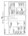
- FIG. 3 is a block diagram showing an example of a specific circuit configuration of the above-described illumination device 10 with a video projection function.
- the illumination device with a video projection function 10 includes a projection type video display unit 100 (small projector 30 in FIG. 2) having a video projection function and a lighting unit 200 having an illumination light irradiation function.
- An operation signal input unit 301 is an operation button or a light receiving unit of a remote controller, and inputs an operation signal from a user.
- the projection optical system 101 is an optical system that projects an image onto an upper surface (display surface or projection surface) 61, and includes at least one of a lens and a mirror.
- the display element 102 is an element that generates an image by modulating transmitted light or reflected light.
- a transmissive liquid crystal panel, a reflective liquid crystal panel, a DMD (Digital Micromirror Device: registered trademark) panel, or the like is used.
- the display element driving unit 103 sends a drive signal corresponding to the video signal to the display element 102.
- the light source 105 generates light for image projection, and uses a high-pressure mercury lamp, a xenon lamp, an LED light source, a laser light source, or the like.
- the power source 106 converts an AC current input from the outside into a DC current and supplies power to the light source 105. Further, the power supply 106 supplies necessary DC currents to the other components.
- the illumination optical system 104 condenses the light generated by the light source 105, makes it more uniform, and irradiates the display element 102 with it.
- the cooling unit 115 cools each part, such as the light source 105, the power source 106, or the display element 102, which is in a high temperature state, by air cooling or liquid cooling as necessary.
- the operation input unit 107 is an operation button or a light receiving unit of a remote controller, and inputs an operation signal from the user.
- the operation input unit 107 may receive an infrared signal or a radio signal from the operation panel 70 of FIG.
- the operation input unit 107 may be omitted.
- the video signal input unit 131 connects an external video output device and inputs video data.
- the audio signal input unit 133 inputs an audio data by connecting an external audio output device.
- the audio output unit 140 can perform audio output based on the audio data input to the audio signal input unit 133. Further, the audio output unit 140 may output a built-in operation sound or an error warning sound.
- the communication unit 132 is connected to an external information processing apparatus and inputs / outputs various control signals.
- the communication unit 132 may perform wired communication or wireless communication with the operation panel 70 of FIG.
- the nonvolatile memory 108 stores various data used for the projector function.
- the memory 109 stores video data to be projected and control data for the apparatus.
- the control unit 110 controls the operation of each connected unit.
- the image adjustment unit 160 performs image processing on the video data input by the video signal input unit 131.
- Examples of the image processing include scaling processing for enlarging, reducing, and deforming the image, bright adjustment processing for changing the brightness, contrast adjustment processing for changing the contrast curve of the image, and components obtained by decomposing the image into light components. Retinex processing for changing the weighting for each.
- the storage unit 170 records video, images, audio, various data, and the like.
- video, image, audio, various data, etc. may be recorded in advance at the time of product shipment, and video, image, audio, various data, etc. acquired from an external device, an external server, etc. via the communication unit 132 may be used. It may be recorded.
- Video, images, various data, and the like recorded in the storage unit 170 may be output as projection video via the display element 102 and the projection optical system 101.
- the sound recorded in the storage unit 170 may be output as sound from the sound output unit 140.
- the projection type image display unit 100 can be provided with various functions.
- the projection display unit 100 does not necessarily have all the above-described configurations. Any configuration may be used as long as it has a function of projecting an image.
- the control unit 201 controls each unit to be connected.
- the operation input unit 203 is an operation button or a light receiving unit of a remote controller, and inputs an operation signal from the user.
- the operation input unit 203 may receive an infrared signal or a radio signal from the operation panel 70 of FIG.
- the operation input unit 203 may be omitted.
- the nonvolatile memory 204 stores various data used in the lighting unit 200.
- the power source 202 converts an AC current input from the outside into a DC current and supplies power to the light emitting element drivers (210, 220, etc.). Further, the power source 202 supplies necessary DC currents to the other units.
- the light emitting element drivers (210, 220, etc.) emit light from the light emitting elements (211, 212, 213, 221, 222, 223, etc.) based on the control of the control unit 201 using the power supplied from the power source 202.
- the light emitting element serves as a light source of illumination light emitted from the illumination unit 200.
- the light emitting element driver A210 collectively drives n light emitting elements A1, A2,... An (211, 212, 213, etc.) connected in series.
- the light emitting element driver A 210 changes the luminance, color, and the like of these light emitting elements based on the control of the control unit 201.
- the light emitting element driver B220 collectively drives m light emitting elements B1, B2,... Bm (221, 222, 223, etc.) connected in series.
- the light emitting element driver B220 changes the luminance and color of these light emitting elements based on the control of the control unit 201.
- FIG. 3 two examples of a light emitting element driver and a set of a plurality of light emitting elements are shown, but one or three or more sets may be used. What is necessary is just to increase / decrease as needed.
- the illumination unit 200 can emit illumination light with variable brightness or color.
- Example 1 Since the outline of the internal configuration of the first embodiment is the same as that of FIG. 2, the description thereof is omitted here, and the cooling mechanism that is a feature thereof will be described below with reference to FIG.
- the disk-shaped substrate 21 constituting the above-described illumination light source 20 is formed by forming a metal such as aluminum or copper having excellent thermal conductivity into a cylindrical shape.
- the semiconductor light-emitting element 22 formed of a plurality of LEDs described above is attached to the lower surface side of the figure.
- the bottom wall (the wall on the upper surface side of the figure) of the metal container 23 also includes an opening (center part of the figure) through which the wiring from the above-described lighting appliance outlet 51 (see FIG. 2) passes.
- a plurality of openings 24 are formed.
- the above-described outer box-type small projector 30 is housed with the projection lens 31 facing downward, and is fixed at a predetermined position by a fixing member such as a screw 25, for example. It is fixed.
- a power supply unit 80 that supplies required power to the illumination light source 20 and the small projector 30 is also fixed at a predetermined position inside the metal container 23 by a fixing member such as a screw 25.
- a plurality of rod-shaped members 26 are integrally formed on the upper surface wall of the metal container 23, and as is apparent from the drawing, the tips of these rod-shaped members 26 have a conical main body (shade) 11. Is also fixed to a predetermined position by a fixing member such as a screw 25.
- the outer cone-shaped main body (shade) 11 is fixed to the lower end of a holder 40 made of a cylindrical pipe made of a metal such as aluminum having excellent thermal conductivity.
- the illumination light source 20 in order to diffuse the illumination light from the illumination light source 20 and uniformly irradiate it downward, it is attached so as to cover the lower opening of the main body 11 and is attached to the diffuser plate 12 from the small projector 30 at its center.
- a plurality of small-diameter openings (small-diameter openings) 15 are formed in the periphery thereof.
- the ambient air heated by the exhaust heat of the light source flowing out from the exhaust port 35 of the small projector 30 and the heat generated from the power supply unit 80 is indicated by a bold line in the figure.
- the pipe rises. Thereafter, it flows out through the upper part of the holder 40 that is the pipe and the vent opening 43 formed in the outlet cover 41.
- the external air is the opening 15 or the opening 14 which is a small diameter opening formed in the diffusion plate 12.
- the main body (shade) 11 flows into the main body (shade) 11 through a gap between the bowl-shaped portion 21 which is a disc-shaped substrate and the main body (shade) 11, and part of the main body (shade) 11 passes through the small projector 30. Move to top of (shade) 11.
- the air inside the main body (shade) 11 can be efficiently replaced (circulated) with the external air by the convection due to the chimney effect by the cylindrical pipe 40. That is, the opening 15 and the opening 14 which are small-diameter openings serve as intake openings into the main body (shade) 11.
- heat generated from the heat generating part (in this example, mainly the light source 20 for illumination, the small projector 30, and the power supply part 80) housed inside the main body (shade) 11 is By transmitting to the air flow circulating inside, it is possible to efficiently discharge to the outside and cool the heat generating portion.
- the light outlet of the light source of the small projector 30 serving as a heat generation source is positioned lower than the lower flow path opening 44 of the holder 40 in the vertical direction.
- 35 and an illumination light source 20 serving as a heat generation source and further, an opening 14 serving as an air inlet to the space formed by the main body 11 and the diffusion plate 12 at a position lower in the vertical direction than these heat generation sources It is desirable to arrange the opening 15.
- the opening 15 that is a small-diameter opening is provided in the diffusion plate 12, but it is not necessarily provided in the diffusion plate 12. You may provide in the side surface of the main body 11.
- the opening shape of the opening 15, which is a small-diameter opening is a small diameter, but it may be an elongated slit shape.
- FIG. 5 shows an outline of the internal configuration of the second embodiment. Since the schematic configuration is the same as that of FIG. 2, the description thereof is omitted here, and the cooling mechanism that is a feature thereof is described below. This will be described with reference to FIG.
- the above-described metal container 23 is extended upward and formed integrally with the lower end of the holder 40, which is a cylindrical pipe made of metal such as aluminum. Is.
- the light source 20 for illumination it is set as the disk-shaped board
- substrate 21 which comprises the light source for illumination by forming the bowl-shaped part in the lower end of the metal container 23, and arrange
- a disk-shaped member 26 is fixed and attached to the substantially central portion of the metal container 23, and the small projector 30 and the power supply unit 80 housed in the internal space of the metal container 23 by the member 26. Is fixed at a predetermined position by a fixing member such as a screw 25. Furthermore, a plurality of elongated slit-shaped openings 27 are provided in the upper part of the metal container 23 (above the member 26), whereby the interior space of the main body (shade) 11 and the interior of the metal container 23 are provided. Air permeability between the space is secured. The main body (shade) 11 is held at a predetermined position by a protrusion 28 formed on the upper portion of the metal container 23.
- the diffusion plate 12 is the same as described above in order to diffuse the illumination light from the illumination light source 20 attached so as to cover the lower opening of the main body 11 and uniformly irradiate it downward.
- the surrounding air heated by the exhaust heat of the light source flowing out from the exhaust port 35 of the small projector 30 and the heat generation of the power supply unit 80 is indicated by a bold line in the figure. As shown by the arrow, it rises in the internal space of the metal container 23. Further, the air heated by the bowl-shaped portion 21 which is a disk-shaped substrate of the illumination light source 20 moves upward from there, and passes through a plurality of slit-shaped openings 27 formed in the upper portion of the metal container 23. It flows into the internal space of the metal container 23 of FIG.
- the opening 15 and the opening 14 which are small-diameter openings serve as intake openings into the main body (shade) 11.
- the heat generated from the semiconductor light emitting element 22 of the illumination light source 20 is generated from the bowl-shaped portion of the metal container 23 that is a disk-shaped substrate. 6 is transmitted through the wall surface of the metal container 23 in FIG. 6 to the holder 40 which is a metal cylindrical pipe excellent in thermal conductivity formed integrally therewith. Similarly, the heat generated from the small projector 30 and the power supply unit 80 is also applied to the wall surface of the metal container 23 and the metal through the disk-shaped member 26 of FIG. It is transmitted to the holder 40 which is a cylindrical pipe made of metal.
- the heat generation is directed to the metal metal container 23 having excellent thermal conductivity and the holder 40 which is a cylindrical pipe. Therefore, it is possible to more efficiently realize the cooling of the heat generating portion.
- a small projector serving as a heat generation source at a position lower than the lower flow path opening 44 of the holder 40 in the vertical direction.
- 30 light source exhaust ports 35 and an illumination light source 20 serving as a heat generation source are arranged, and an air inflow port to a space formed by the main body 11 and the diffusion plate 12 at a position lower in the vertical direction than these heat generation sources. It is desirable to arrange the opening 14 and the opening 15.
- the opening 15 that is a small-diameter opening is provided in the diffusion plate 12, but it is not always necessary to provide the diffusion plate 12. You may provide in the side surface of the main body 11.
- the opening shape of the opening 15 that is a small-diameter opening is a small diameter, but may be a long and narrow slit shape.
- the diameter (A: cross-sectional area [m 2 ] of the chimney) and the length (h: the height of the chimney) which are metal cylindrical pipes. It is important to set [m]) appropriately.
- the diameter of the holder 40, which is a cylindrical pipe will need to be set in consideration of the wiring 42 from the outlet for the lighting fixture housed therein.
- a fan for performing forced ventilation is further employed.
- the configuration is shown.
- the holder in addition to the configuration shown in the first embodiment (or the configuration of the second embodiment), the holder is a metal cylindrical pipe.
- a small ventilation fan 45 is attached to a part (upper part) of 40 and the opening 43 of the hemispherical outlet cover 41.
- the ventilation fan 45 may be attached to one of the part (upper part) 46 of the holder 40 or the opening 43 of the outlet cover 41.
- the ventilation fan 45 by attaching the ventilation fan 45, the circulating air flow rate is increased, so that the heat generating portion can be cooled more efficiently.
- the ventilation fan 45 is preferably attached at a position close to the ceiling surface 50, such as the upper part of the holder 40, which is a cylindrical pipe as described above, and the hemispherical outlet cover 41. This is because the accompanying ventilation fan 45 is arranged at a position further away from the user to obtain an effect of reducing the adverse effects of noise (silent effect).
- these ventilation fans 45 may be provided inside the main body (shade) 11 and turned on / off using a temperature detected by a temperature sensor, or the operation panel 70 is used. Then, the operator may control it.
- the present invention is not limited to the above-described embodiments, and includes various modifications.
- the above-described embodiments are described in detail for the entire system in order to explain the present invention in an easy-to-understand manner, and are not necessarily limited to those having all the configurations described.
- a part of the configuration of one embodiment can be replaced with the configuration of another embodiment, and the configuration of another embodiment can be added to the configuration of one embodiment.
- SYMBOLS 10 Illuminating device, 11 ... Main body (shade) (shade), 12 ... Diffusing plate, 14, 15 ... Opening part, 20 ... Light source for illumination, 23 ... Metal container, 30 ... Small projector, 32 ... Projection lens, 40 ... Holder, 41 ... outlet cover, 43 ... opening, 44 ... lower flow path opening, 45 ... cooling fan
Landscapes
- Engineering & Computer Science (AREA)
- General Engineering & Computer Science (AREA)
- Arrangement Of Elements, Cooling, Sealing, Or The Like Of Lighting Devices (AREA)
- Projection Apparatus (AREA)
Abstract
発光素子やプロジェクタからの発熱を効率よく外部に放出することが可能な優れた映像投射機能を有する照明装置を提供する。天井面に固定された保持具に吊り下げた状態で保持され、照明光を発する照明装置であって、筺体の内部に配置される前記照明光を生成するための光源と、当該筺体の一部に取り付けた拡散板であって、前記光源からの照明光を拡散する拡散板と、前記筺体と前記拡散板の一部が形成する空間の内部に配置され、投射面に映像を投射するプロジェクタとを備え、前記保持具は内部を中空に形成しており、前記筺体は、その内部に配置された前記光源と前記プロジェクタにより暖められた空気を前記保持具の中空部に導くように構成されている。
Description
本発明は、照明装置に関する。
天井や壁面に取り付けて、各種の機能を利用することができる通信機能モジュールをシーリングライトに取り付ける技術が、以下の特許文献1に開示されている。
更に、照明光と映像を合わせた空間演出を可能とする、画像投影装置付き照明装置が、以下の特許文献2に開示されている。
しかしながら、上述した従来技術には、プロジェクタはブロック図や簡易的な外形が開示されるのみであり、照明装置内におけるプロジェクタやLED等の半導体発光素子を利用した照明用光源からの発熱を外部へ放出するための機能を考慮したものは開示されていない。
一般に、映像投射機能を有する照明装置は、天井面に取り付けられて使用され、照明用光源からの照明光を、例えば、室内に配置されたテーブル等の表面上に照射すると共に、プロジェクタからの映像光を所望の位置に投射する。そのため、本体(又は筺体、又はシェードとも言う)の内部では、照明用光源からの発熱と同時にプロジェクタからの発熱が予想される。特に、照明とプロジェクタとを長時間に亘って共用した場合には、それら複数の発熱源での発熱により内部の温度が上昇してしまい、LED等の発光素子の発光効率を低減し、又は、プロジェクタから投射される映像に劣化するなどの悪影響を及ぼすこととなる。しかしながら、上記の従来技術は、映像投射機能を有する照明装置における複数の発熱源からの放熱を効率的に外部に放出するための機能や構造についての考慮は、未だ十分に払われてはいなかった。
そこで、本発明は、上述した従来技術における問題点に鑑みて達成されたものであり、その目的は、内部に発光素子やプロジェクタを収納してなる映像投射機能を有する照明装置であって、当該発光素子やプロジェクタからの発熱を効率よく外部に放出することが可能であり、複数の発熱源での発熱による悪影響を低減可能な実用的にも優れた照明装置を提供することにある。
上記の目的を達成するため、本発明によれば、天井面に固定された保持具に吊り下げた状態で保持され、照明光を発する照明装置であって、筺体の内部に配置される前記照明光を生成するための光源と、当該筺体の一部に取り付けた拡散板であって、前記光源からの照明光を拡散する拡散板と、前記筺体と前記拡散板の一部が形成する空間の内部に配置され、投射面に映像を投射するプロジェクタとを備え、前記保持具は内部を中空に形成しており、前記筺体は、その内部に配置された前記光源と前記プロジェクタにより暖められた空気を前記保持具の中空部に導くように構成されている照明装置が提供される。
上述した本発明によれば、内部に発光素子やプロジェクタを収納してなる映像投射機能を有する照明装置において、当該発光素子やプロジェクタからの発熱を効率よく外部に放出することが可能であり、複数の発熱源での発熱による悪影響を低減可能な実用的にも優れた照明装置が提供されるという優れた効果を発揮する。
以下、本発明の実施の形態について、添付の図面を参照しながら、詳細に説明する。
まず、添付の図1は、本発明の一実施の形態である映像投射機能付き照明装置の外観構成を示しており、特に、図には、天井面から吊るすような形態で取り付けられる、所謂、ペンダント型と呼ばれる照明装置に映像投射機能を搭載した映像投射機能付き照明装置が示されている。しかしながら、本発明は、これにのみ限定されることなく、その他にも、後にも述べるように、天井面に取り付けられる、所謂、シーリング型と呼ばれる照明装置に適用することも可能であろう。
この図からも明らかなように、映像投射機能付き照明装置10は、例えば、キッチン、ダイニングルーム、又は、居間、オフィス等の空間を構成する壁面、または、天井面50などに取り付けて使用される。より具体的には、図にも示すように、室内に設置されたテーブルや机60の上方において、所定の高さ、又は、天井面に一体に設置される。この映像投射機能付き照明装置10は、照明光をテーブルや机の上面に照射する照明機能と、当該テーブル又は机60の上面(表示面または投射面)61に各種の映像を投射して表示する映像投射機能と両方有する照明装置である。なお、図1における保持具40は、特に、ペンダント型の照明装置10を天井面から所望の位置に吊り下げた状態で保持するための保持具である、例えば、アルミニウム等の金属からなる円筒状のパイプを示している。
映像投射機能で映像を投射したい水平面テーブル又は机などは、映像投射機能を用いない状態で使用する際などに照明機能で照明する対象になる可能性が高い。よって、前記映像投射機能で映像を投射する領域と前記照明機能の照明光の照明範囲は少なくとも一部が重畳することが望ましい。
また、映像投射機能付き照明装置は、制御部を搭載することにより、照明機能で照射する照明光と映像投射機能で投射する映像とはそれぞれON/OFFできるように構成するのが望ましい。なお、本例では、利用者は、壁面に取り付けられた操作パネル70を介して、かかる操作を行う。
図2は、上記図1に示した映像投射機能付き照明装置10の内部構成の概略を示している。この図にも明らかなよう、アルミニウム等の金属からなる円筒状のパイプからなる保持具40の上端には、半球状のコンセントカバー41が取り付けられており、当該コンセントカバー41は、天井面に設置された照明器具用のコンセント51を覆うように天井面50に固定される。他方、上記保持具40の下端には、例えば、合成樹脂の金型成型により形成した、外形略円筒又は円錐状の本体(又は筺体、又はシェードとも言う)11が取り付けられており、その内部には、ほぼ均等な照射光が得られるように、例えば、熱伝導性に優れた金属などからなる円盤状の基板21の面上に、複数の半導体発光素子(LED)22を配列して構成された照明用光源20と共に、各種の映像を投射して表示するための外形箱型の小型プロジェクタ30を備えている。
また、図中の電源部80は、上記照明器具用のコンセントを介して入力した商用交流電源を所望の交流電圧又は直流電圧に変換する電源部を示しており、当該電源部80は、上記小型プロジェクタ30の上部に配置されており、ここでは図示しない配線を介して、上述した照明用光源20や小型プロジェクタ30に所要の電力を供給する。なお、図中の配線42は、上記照明器具用のコンセントからの商用交流電源を導くための配線を示しており、当該配線42は、上記保持具40である円筒状のパイプの内部に収納されている。また、図中の開口部43は、上記コンセントカバー41と共に、上記パイプである保持具40の上部に形成された開口部であり、後にも説明するように、通気口を形成している。
また、上記本体11の下方開口部を覆うように拡散板12が取り付けられており、上記照明用光源20からの照明光を拡散して下方に均一に照射する。開口部14は、当該拡散板12の一部に形成された開口部であり、小型プロジェクタ30からの映像は当該開口部14を通して投射される。なお、ここでは、本体(シェード)11の外形を円筒又は円錐状として説明したが、しかしながら、本発明は、これに限定されることなく、その他の形状、例えば、箱型のものであってもよい。
また、拡散板12には、吸気のための開口部15を設けてもよい。開口部15の形状例は後述する。
ここで、本体11内の空気が上昇して円筒状のパイプである保持具40の内部の中空部に流入する際に通過する下部流路開口44がある。そして下部流路開口44よりも鉛直方向で低い位置に、熱発生源となる小型プロジェクタ30の光源(例えば、水銀ランプやLED、レーザー光源等)の排熱の排気口35と、熱発生源となる照明用光源20を配置し、さらにこれら熱発生源よりも鉛直方向で低い位置に本体11と拡散板12からなる空間への空気の流入口となる開口部14や開口部15を配置する構成になっている。なお、下部流路開口44は開口部(通気口)43よりも鉛直方向で低い位置に形成される。
図3は、上述した映像投射機能付き照明装置10の具体的な回路構成の一例を示すブロック図である。映像投射機能付き照明装置10には、映像投射機能を有する投射型映像表示ユニット100(図2の小型プロジェクタ30)と照明光照射機能を有する照明ユニット200が含まれている。操作信号入力部301は、操作ボタンやリモコンの受光部であり、ユーザからの操作信号を入力する。
次に、投射型映像表示ユニット100の構成を説明する。投射光学系101は、映像を上面(表示面または投射面)61へ投射する光学系で、レンズまたはミラーの少なくとも一方を含む。表示素子102は、透過する光または反射する光を変調して映像を生成する素子で、例えば、透過型液晶パネル、反射型液晶パネル、DMD(Digital Micromirror Device:登録商標)パネル等を用いる。表示素子駆動部103は、表示素子102に対して映像信号に応じた駆動信号を送る。光源105は映像投射用の光を発生するもので、高圧水銀ランプ、キセノンランプ、LED光源、レーザー光源等を用いる。電源106は、外部から入力されるAC電流をDC電流に変換して、光源105に電力を供給する。さらに電源106は、その他各部にそれぞれ必要なDC電流を供給する。照明光学系104は、光源105で発生した光を集光し、より均一化して表示素子102に照射する。冷却部115は、光源105、電源106または表示素子102など、高温状態になる各部位を空冷方式や液冷方式で必要に応じて冷却する。操作入力部107は、操作ボタンやリモコンの受光部であり、ユーザからの操作信号を入力する。操作入力部107は、図1の操作パネル70からの赤外線信号や無線信号を受信してもよい。照明装置10の操作信号入力部301からの信号が投射型映像表示ユニット100に入力される場合には、操作入力部107がない構造にしても良い。
映像信号入力部131は、外部の映像出力装置を接続して映像データを入力する。音声信号入力部133は、外部の音声出力装置を接続して音声データを入力する。音声出力部140は、音声信号入力部133に入力された音声データに基づいた音声出力を行うことが可能である。また、音声出力部140は内蔵の操作音やエラー警告音を出力してもよい。通信部132は、例えば、外部の情報処理装置と接続し、各種の制御信号を入出力する。通信部132は、図1の操作パネル70と有線通信または無線通信をしてもよい。
不揮発性メモリ108は、プロジェクタ機能で用いる各種データを格納する。メモリ109は、投射する映像データや装置の制御用データを記憶する。制御部110は、接続される各部の動作を制御する。
画像調整部160は、映像信号入力部131で入力した映像データに対して画像処理を行うものである。当該画像処理としては、例えば、画像の拡大、縮小、変形等を行うスケーリング処理、輝度を変更するブライト調整処理、画像のコントラストカーブを変更するコントラスト調整処理、画像を光の成分に分解して成分ごとの重みづけを変更するレティネックス処理等がある。
ストレージ部170は、映像、画像、音声、各種データなどを記録するものである。例えば、製品出荷時に予め映像、画像、音声、各種データなどを記録しておいてもよく、通信部132を介して外部機器や外部のサーバ等から取得した映像、画像、音声、各種データなどを記録してもよい。ストレージ部170に記録された映像、画像、各種データなどは、表示素子102と投射光学系101を介して投射映像として出力すればよい。ストレージ部170に記録された音声は音声出力部140から音声として出力すればよい。
以上説明したように、投射型映像表示ユニット100には様々な機能を載せることが可能である。しかしながら、投射型映像表示ユニット100は必ずしも上述した構成の全てを有する必要はない。映像を投射する機能があればどのような構成でもよい。
次に、照明ユニット200の構成について説明する。制御部201は、接続される各部を制御する。操作入力部203は、操作ボタンやリモコンの受光部であり、ユーザからの操作信号を入力する。操作入力部203は、図1の操作パネル70からの赤外線信号や無線信号を受信してもよい。照明装置10の操作信号入力部301からの信号が照明ユニット200に入力される場合には、操作入力部203がない構造にしても良い。不揮発性メモリ204は、照明ユニット200で用いる各種データを格納する。
電源202は、外部から入力されるAC電流をDC電流に変換して、発光素子ドライバ(210、220など)に電力を供給する。さらに電源202は、その他各部にそれぞれ必要なDC電流を供給する。発光素子ドライバ(210、220など)は、電源202から供給される電力を用い、制御部201の制御に基づいて発光素子(211、212、213、221、222、223など)を発光する。当該発光素子が、照明ユニット200の発する照明光の光源となる。例えば、図3の例では、発光素子ドライバA210は、直列で接続したn個の発光素子A1、A2、・・・An(211、212、213など)を纏めて駆動する。発光素子ドライバA210は、制御部201の制御に基づいて、これらの発光素子の輝度や色などを変更する。同様に、発光素子ドライバB220は、直列で接続したm個の発光素子B1、B2、・・・Bm(221、222、223など)を纏めて駆動する。発光素子ドライバB220は、制御部201の制御に基づいて、これらの発光素子の輝度や色などを変更する。このように構成することにより、発光素子ドライバ毎に複数の発光素子の輝度や色を変える制御が可能となる。図3の例では、発光素子ドライバと複数の発光素子のセットを2つの例を示したが、1つでも3つ以上でも構わない。必要に応じて増減すればよい。
以上説明した構成により、照明ユニット200は、輝度または色の少なくとも一方が可変の照明光を発することができる。
続いて、上記の概略を説明した映像投射機能を有する照明装置において、本発明の特徴である、照明用光源20及びプロジェクタ30を冷却するための機構に関連し、その詳細について、具体的には、実施例1~3として、以下に説明する。
<実施例1>
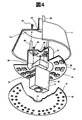
この実施例1の内部構成の概略は、上記図2と同様であることから、ここではその説明は省略し、その特徴となる冷却機構について、以下に図4を参照しながら説明する。
この実施例1の内部構成の概略は、上記図2と同様であることから、ここではその説明は省略し、その特徴となる冷却機構について、以下に図4を参照しながら説明する。
図4にも示すように、本実施例1では、上述した照明用光源20を構成する円盤状の基板21は、熱伝導性に優れたアルミニウムや銅等の金属などを筒状に形成してなる金属容器23の下端に形成された鍔状部として形成されており、上述した複数のLEDからなる半導体発光素子22は、図の下面側に取り付けられている。また、金属容器23の底壁(図の上面側の壁)には、上述した照明器具用のコンセント51(図2を参照)からの配線を通す開口部(図の中央部)をも含め、複数の開口部24が形成されている。そして、当該金属容器23の内部空間には、上述した外形箱型の小型プロジェクタ30が、その投射レンズ31を下側にして収納されており、例えば、ネジ25等の固定部材により所定の位置に固定されている。また、照明用光源20や小型プロジェクタ30に所要の電力を供給する電源部80も、同様に、ネジ25等の固定部材により、金属容器23の内部の所定の位置に固定されている。
また、金属容器23の上面壁には、複数の棒状の部材26が一体に形成されており、図からも明らかなように、これらの棒状部材26の先端は外形円錐状の本体(シェード)11の上側内壁面111に当接し、やはり、ネジ25等の固定部材により所定の位置に固定されている。なお、外形円錐状の本体(シェード)11は、熱伝導性に優れたアルミニウム等の金属からなる円筒状パイプからなる保持具40の下端に固定されている。
一方、上記照明用光源20からの照明光を拡散して下方に均一に照射するために本体11の下方開口部を覆うように取り付けられ拡散板12には、その中央部に、小型プロジェクタ30からの映像光を通過させるための開口部14が形成されると共に、その周辺部には、複数の小さな径の開口部(小径開口)15が形成されている。
ここで、再び上記図2に戻り、上述した構成によれば、小型プロジェクタ30の排気口35から流出する光源の排熱や電源部80からの発熱により暖められた周囲の空気は、図に太線の矢印で示すように、金属容器23の内部空間内で、更には、照明用光源20の円盤状の基板である鍔状部21で暖められた空気は、そこから本体(シェード)11内の空間を上方に向かって移動する。その後、これらの空気は本体(シェード)11の上部を通って、下部流路開口44から、熱伝導性に優れた金属製の円筒状パイプである保持具40の内部に流入し、所謂、煙突効果により、当該パイプ内を上昇する。その後、上記パイプである保持具40の上部、及び、上記コンセントカバー41に形成した通気用の開口部43を通って外部へ流出する。一方、この発熱により暖められた空気の外部への流出に伴い、図に細線の矢印で示すように、外部の空気は、拡散板12に形成された小径開口である開口部15や開口部14を通って本体(シェード)11の内部に流入し、更に、円盤状の基板である鍔状部21と本体(シェード)11との隙間を、また、その一部は小型プロジェクタ30を通って本体(シェード)11の上部へ移動する。即ち、円筒状パイプ40による煙突効果による対流によって、本体(シェード)11の内部の空気を、効率的に、外部の空気と入れ替える(循環させる)ことが可能となる。
すなわち、小径開口である開口部15や開口部14は、本体(シェード)11内への吸気開口としての役割を果たす。
すなわち、小径開口である開口部15や開口部14は、本体(シェード)11内への吸気開口としての役割を果たす。
即ち、上述した煙突効果により、本体(シェード)11の内部に収納された発熱部(本例では、主に、照明用光源20、小型プロジェクタ30、更には、電源部80)からの発熱を、その内部を循環する空気流に伝達することにより、効率的に、外部に排出して、発熱部を冷却することが可能となる。
この冷却効果を高めるためには、図2、図3に示すように、保持具40の下部流路開口44よりも鉛直方向で低い位置に、熱発生源となる小型プロジェクタ30の光源の排気口35と、熱発生源となる照明用光源20を配置し、さらにこれら熱発生源よりも鉛直方向で低い位置に本体11と拡散板12からなる空間への空気の流入口となる開口部14や開口部15を配置することが望ましい。
なお、図2、図3の例では、小径開口である開口部15を拡散板12に設けたが、必ずしも拡散板12に設ける必要はない。本体11の側面に設けても構わない。図2、図3の例では、小径開口である開口部15の開口形状は小径としたが、細長いスリット形状でも構わない。
<実施例2>
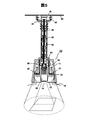
続いて、実施例2の内部構成の概略を図5に示すが、その概略構成は上記図2と同様であることから、ここではその説明は省略し、その特徴となる冷却機構について、以下に図6を参照しながら説明する。
続いて、実施例2の内部構成の概略を図5に示すが、その概略構成は上記図2と同様であることから、ここではその説明は省略し、その特徴となる冷却機構について、以下に図6を参照しながら説明する。
図6からも明らかなように、本実施例2では、上述した金属容器23を上方に延長し、上記アルミニウム等の金属からなる円筒状のパイプである保持具40の下端部に一体に形成したものである。なお、照明用光源20については、金属容器23の下端に鍔状部を形成して複数のLEDからなる半導体発光素子22を配置することにより、照明用光源を構成する円盤状の基板21とすることは、上記と同様である。
また、本実施例2では、上記金属容器23の略中央部に円盤状の部材26を固定して取り付け、当該部材26により、金属容器23の内部空間に収納される小型プロジェクタ30や電源部80を、ネジ25等の固定部材によって所定の位置に固定している。更には、金属容器23の上部には(当該部材26の上方)、複数の細長いスリット状の開口27が設けられており、これにより、本体(シェード)11の内部空間と当該金属容器23の内部空間との間の通気性を確保している。そして、本体(シェード)11は、上記金属容器23の上部に形成された突起部28によって所定の位置に保持されている。
なお、本体11の下部開口部を覆うように取り付けられた、照明用光源20からの照明光を拡散して下方に均一に照射するため拡散板12は、上記と同様である。
以上に述べた構成によれば、上記図5に戻って、小型プロジェクタ30の排気口35から流出する光源の排熱や電源部80の発熱により暖められたその周囲の空気は、図に太線の矢印で示すように、金属容器23の内部空間において上昇する。更に、照明用光源20の円盤状の基板である鍔状部21で暖められた空気は、そこから上方に向かって移動し、金属容器23の上部に形成された複数のスリット状の開口27を通って図6の金属容器23の内部空間に流入する。その後、これらの空気は、金属容器23の上部を通って、下部流路開口44から、熱伝導性に優れた金属製の円筒状パイプである保持具40の内部に流入し、所謂、煙突効果によりパイプ内を上昇し、上記パイプである保持具40の上部、及び、上記コンセントカバー41に形成した通気用の開口部43から外部へ流出する。そして、この発熱により暖められた空気の外部への流出に伴い、図に細線の矢印で示すように、外部の空気が、拡散板12に形成された小径開口である開口部15や開口部14を通り、その後、円盤状の基板である鍔状部21と本体(シェード)11との隙間を通って、本体(シェード)11の内部に流入する。即ち、円筒状パイプである保持具40による煙突効果による対流によって、本体(シェード)11の内部の空気を、効率的に、外部の空気と入れ替える(循環させる)ことが可能となることは上記と同様である。
すなわち、小径開口である開口部15や開口部14は、本体(シェード)11内への吸気開口としての役割を果たす。
更に、本実施例2の構成によれば、図5に破線の矢印で示すように、照明用光源20の半導体発光素子22からの発熱は、円盤状の基板である金属容器23の鍔状部21に伝達され、図6の当該金属容器23の壁面を通って、その上部に一体に形成した熱伝導性に優れた金属製の円筒状パイプである保持具40へ伝達される。また、小型プロジェクタ30や電源部80からの発熱も、同様に、属容器23の略中央部に固定された図6の円盤状の部材26を介して、当該金属容器23の壁面、そして、金属製の円筒状パイプである保持具40へ伝達される。
即ち、本実施例2の構成によれば、上述した煙突効果により生じる対流による冷却効果に加え、発熱が、熱伝導性に優れた金属製の金属容器23や円筒状パイプである保持具40へも伝達されることから、発熱部の冷却をより効率的に実現することが可能となる。
実施例2においても、この冷却効果を高めるためには、図5、図6に示すように、保持具40の下部流路開口44よりも鉛直方向で低い位置に、熱発生源となる小型プロジェクタ30の光源の排気口35と、熱発生源となる照明用光源20を配置し、さらにこれら熱発生源よりも鉛直方向で低い位置に本体11と拡散板12からなる空間への空気の流入口となる開口部14や開口部15を配置することが望ましい。
なお、図5、図6の例では、小径開口である開口部15を拡散板12に設けたが、必ずしも拡散板12に設ける必要はない。本体11の側面に設けても構わない。図5、図6の例では、小径開口である開口部15の開口形状は小径としたが、細長いスリット形状でも構わない。
なお、ここでは、一般的に、吸気流量と外気温度との関係は、下記の式で表される。
Q=C・A・√2g・h・(Ti-T0)/Ti
Q:煙突効果による空気流量[m3/s]
A:煙突の断面積[m2]
C:流量係数(通常0.65~0.7)
g:重量加速度=9.80665[m/s2]
h:煙突の高さ[m]
T0:外気の絶対温度[K]
Ti:煙突内の平均温度[K]
Q=C・A・√2g・h・(Ti-T0)/Ti
Q:煙突効果による空気流量[m3/s]
A:煙突の断面積[m2]
C:流量係数(通常0.65~0.7)
g:重量加速度=9.80665[m/s2]
h:煙突の高さ[m]
T0:外気の絶対温度[K]
Ti:煙突内の平均温度[K]
そこで、所望の冷却効果を得るためには、特に、金属製の円筒状パイプである保持具40の径(A:煙突の断面積[m2])やその長さ(h:煙突の高さ[m])を適切に設定することが重要である。特に、円筒状パイプである保持具40の径については、その内部に収納される照明器具用のコンセントからの配線42を考慮して設定する必要があろう。
<実施例3>
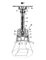
本実施例3では、上記の実施例1又は2で示した煙突効果や伝熱作用を利用した構成に加え、更には、強制換気を行うためのファンを採用したものであり、図7にその構成を示す。
本実施例3では、上記の実施例1又は2で示した煙突効果や伝熱作用を利用した構成に加え、更には、強制換気を行うためのファンを採用したものであり、図7にその構成を示す。
図7からも明らかなように、本実施例3では、上記の実施例1で示した構成(又は実施例2の構成でもよい)に加え、更に、上記金属製の円筒状パイプである保持具40の一部(上部)及び半球状のコンセントカバー41の開口部43に、小型の換気ファン45を取り付けたものである。換気ファン45は、保持具40の一部(上部)46またはコンセントカバー41の開口部43の一方に取り付けられてもよい。
即ち、本実施例3では、換気ファン45を取り付けることにより、循環する空気流量を増大させ、もって、より効率的に、発熱部を冷却することを可能とするものである。なお、換気ファン45は、上述したように円筒状パイプである保持具40の上部、半球状のコンセントカバー41のように、天井面50に近接した位置に取り付けることが好ましく、これは、騒音原ともなる換気ファン45を利用者からより離れた位置に配置して、騒音による悪影響を低減する効果(静音効果)を得るためである。
また、これらの換気ファン45は、例えば、本体(シェード)11の内部に設けて温度センサにより検出される温度を利用してON/OFFするようにしてもよく、又は、上記操作パネル70を利用して操作者が制御するようにしてもよい。
以上、本発明の種々の実施例になる映像投射機能付き照明装置について種々述べたが、しかしながら、本発明は、上述した実施例のみに限定されるものではなく、様々な変形例が含まれる。例えば、上記した実施例は本発明を分かりやすく説明するためにシステム全体を詳細に説明したものであり、必ずしも説明した全ての構成を備えるものに限定されるものではない。また、ある実施例の構成の一部を他の実施例の構成に置き換えることが可能であり、また、ある実施例の構成に他の実施例の構成を加えることも可能である。また、各実施例の構成の一部について、他の構成の追加・削除・置換をすることが可能である。
10…照明装置、11…本体(筺体)(シェード)、12…拡散板、14,15…開口部、20…照明用光源、23…金属容器、30…小型プロジェクタ、32…投射レンズ、40…保持具、41…コンセントカバー、43…開口部、44…下部流路開口、45…冷却ファン
Claims (10)
- 天井面に固定された保持具に吊り下げた状態で保持され、照明光を発する照明装置であって、
筺体の内部に配置される前記照明光を生成するための光源と、
当該筺体の一部に取り付けた拡散板であって、前記光源からの照明光を拡散する拡散板と、
前記筺体と前記拡散板の一部が形成する空間の内部に配置され、投射面に映像を投射するプロジェクタとを備え、
前記保持具は内部を中空に形成しており、
前記筺体は、その内部に配置された前記光源と前記プロジェクタにより暖められた空気を前記保持具の中空部に導くように構成されていることを特徴とする照明装置。 - 前記請求項1に記載した照明装置において、
前記保持具には、内部の中空部を外部に連通するための開口部が形成されていることを特徴とする照明装置。 - 前記請求項2に記載した照明装置において、
前記保持具の内部の中空部の前記開口部よりも鉛直方向で低い位置に、前記筺体から前記保持具の内部の中空部へ空気が流入する際に通過する流路開口部があり、
前記プロジェクタの光源の排熱を排出する排気口と前記照明光を生成するための光源とは、いずれも前記流路開口部よりも鉛直方向で低い位置に配置されることを特徴とする照明装置。 - 前記請求項3に記載した照明装置において、
前記プロジェクタの光源の排熱を排出する排気口と前記照明光を生成するための光源よりも鉛直方向で低い位置に、前記筺体へ空気が流入可能な吸気開口が設けられたことを特徴とする照明装置。 - 前記請求項1に記載した照明装置において、
前記筺体は、更に、その内部に配置された少なくとも前記光源による発熱を前記保持具に伝達するように構成されていることを特徴とする照明装置。 - 前記請求項1~5のいずれか1項に記載した照明装置において、
前記保持具は、伝熱性に優れた部材により形成されていることを特徴とする照明装置。 - 前記請求項1~5のいずれか1項に記載した照明装置において、
前記光源が配置された前記筺体の一部と、前記プロジェクタが配置された前記筺体の一部を、伝熱性に優れた部材により形成されていることを特徴とする照明装置。 - 前記請求項1、2、3、および5のいずれか1項に記載した照明装置において、
前記拡散板の一部には、外部からの空気を前記筺体の内部に導くための開口が形成されていることを特徴とする照明装置。 - 前記請求項2に記載した照明装置において、
前記保持具に形成された前記開口部には、内部の空気を外部に放出するためのファンが取り付けられていることを特徴とする照明装置。 - 前記請求項9に記載した照明装置において、
前記開口部は、前記保持具の上部に形成され、かつ、前記ファンが取り付けられていることを特徴とする照明装置。
Priority Applications (1)
| Application Number | Priority Date | Filing Date | Title |
|---|---|---|---|
| PCT/JP2015/060709 WO2016162913A1 (ja) | 2015-04-06 | 2015-04-06 | 照明装置 |
Applications Claiming Priority (1)
| Application Number | Priority Date | Filing Date | Title |
|---|---|---|---|
| PCT/JP2015/060709 WO2016162913A1 (ja) | 2015-04-06 | 2015-04-06 | 照明装置 |
Publications (1)
| Publication Number | Publication Date |
|---|---|
| WO2016162913A1 true WO2016162913A1 (ja) | 2016-10-13 |
Family
ID=57071879
Family Applications (1)
| Application Number | Title | Priority Date | Filing Date |
|---|---|---|---|
| PCT/JP2015/060709 Ceased WO2016162913A1 (ja) | 2015-04-06 | 2015-04-06 | 照明装置 |
Country Status (1)
| Country | Link |
|---|---|
| WO (1) | WO2016162913A1 (ja) |
Cited By (1)
| Publication number | Priority date | Publication date | Assignee | Title |
|---|---|---|---|---|
| WO2019194173A1 (ja) * | 2018-04-03 | 2019-10-10 | 国立大学法人京都大学 | 医療用プロジェクターの支持構造 |
Citations (5)
| Publication number | Priority date | Publication date | Assignee | Title |
|---|---|---|---|---|
| JPH11144510A (ja) * | 1997-11-06 | 1999-05-28 | Matsushita Electric Ind Co Ltd | 照明装置 |
| JP2006127845A (ja) * | 2004-10-27 | 2006-05-18 | Nec Lighting Ltd | 照明器具 |
| JP2012186118A (ja) * | 2011-03-08 | 2012-09-27 | Toshiba Lighting & Technology Corp | 照明器具 |
| JP2014067634A (ja) * | 2012-09-26 | 2014-04-17 | Gs Yuasa Corp | 照明装置 |
| JP2014170675A (ja) * | 2013-03-04 | 2014-09-18 | Panasonic Corp | 照明装置 |
-
2015
- 2015-04-06 WO PCT/JP2015/060709 patent/WO2016162913A1/ja not_active Ceased
Patent Citations (5)
| Publication number | Priority date | Publication date | Assignee | Title |
|---|---|---|---|---|
| JPH11144510A (ja) * | 1997-11-06 | 1999-05-28 | Matsushita Electric Ind Co Ltd | 照明装置 |
| JP2006127845A (ja) * | 2004-10-27 | 2006-05-18 | Nec Lighting Ltd | 照明器具 |
| JP2012186118A (ja) * | 2011-03-08 | 2012-09-27 | Toshiba Lighting & Technology Corp | 照明器具 |
| JP2014067634A (ja) * | 2012-09-26 | 2014-04-17 | Gs Yuasa Corp | 照明装置 |
| JP2014170675A (ja) * | 2013-03-04 | 2014-09-18 | Panasonic Corp | 照明装置 |
Cited By (1)
| Publication number | Priority date | Publication date | Assignee | Title |
|---|---|---|---|---|
| WO2019194173A1 (ja) * | 2018-04-03 | 2019-10-10 | 国立大学法人京都大学 | 医療用プロジェクターの支持構造 |
Similar Documents
| Publication | Publication Date | Title |
|---|---|---|
| JP6594521B2 (ja) | 照明装置 | |
| KR100683171B1 (ko) | 방열장치 및 그것을 구비하는 프로젝터 | |
| CN108291711B (zh) | 照明装置 | |
| JP6429257B2 (ja) | 照明装置 | |
| JP7113245B2 (ja) | 制御装置、点灯装置及び照明システム | |
| JPWO2018158885A1 (ja) | 照明装置 | |
| US10415776B2 (en) | Illumination apparatus | |
| JP6334001B2 (ja) | 照明装置 | |
| JP2016126114A (ja) | 投影装置及び照明装置 | |
| JP7001994B2 (ja) | 制御装置、照明装置及び照明システム | |
| JP6745051B2 (ja) | 画像投写装置 | |
| JP6291906B2 (ja) | 光源用ハウジング、光源装置、画像投射装置 | |
| JP6321148B2 (ja) | 投写型映像表示装置 | |
| CN109073168B (zh) | 照明装置 | |
| JP2018028965A (ja) | 照明装置 | |
| WO2016060086A1 (ja) | 照明装置 | |
| JP2016066409A (ja) | 照明装置 |
Legal Events
| Date | Code | Title | Description |
|---|---|---|---|
| 121 | Ep: the epo has been informed by wipo that ep was designated in this application |
Ref document number: 15888408 Country of ref document: EP Kind code of ref document: A1 |
|
| NENP | Non-entry into the national phase |
Ref country code: DE |
|
| 122 | Ep: pct application non-entry in european phase |
Ref document number: 15888408 Country of ref document: EP Kind code of ref document: A1 |
|
| NENP | Non-entry into the national phase |
Ref country code: JP |