WO2016159353A1 - 情報統合方法及び装置及びシステム及びプログラム - Google Patents
情報統合方法及び装置及びシステム及びプログラム Download PDFInfo
- Publication number
- WO2016159353A1 WO2016159353A1 PCT/JP2016/060932 JP2016060932W WO2016159353A1 WO 2016159353 A1 WO2016159353 A1 WO 2016159353A1 JP 2016060932 W JP2016060932 W JP 2016060932W WO 2016159353 A1 WO2016159353 A1 WO 2016159353A1
- Authority
- WO
- WIPO (PCT)
- Prior art keywords
- information
- flow
- shape
- scalar
- vector
- Prior art date
- Legal status (The legal status is an assumption and is not a legal conclusion. Google has not performed a legal analysis and makes no representation as to the accuracy of the status listed.)
- Ceased
Links
Images





Classifications
-
- A—HUMAN NECESSITIES
- A61—MEDICAL OR VETERINARY SCIENCE; HYGIENE
- A61B—DIAGNOSIS; SURGERY; IDENTIFICATION
- A61B5/00—Measuring for diagnostic purposes; Identification of persons
- A61B5/05—Detecting, measuring or recording for diagnosis by means of electric currents or magnetic fields; Measuring using microwaves or radio waves
- A61B5/055—Detecting, measuring or recording for diagnosis by means of electric currents or magnetic fields; Measuring using microwaves or radio waves involving electronic [EMR] or nuclear [NMR] magnetic resonance, e.g. magnetic resonance imaging
-
- G—PHYSICS
- G01—MEASURING; TESTING
- G01P—MEASURING LINEAR OR ANGULAR SPEED, ACCELERATION, DECELERATION, OR SHOCK; INDICATING PRESENCE, ABSENCE, OR DIRECTION, OF MOVEMENT
- G01P13/00—Indicating or recording presence, absence, or direction, of movement
-
- G—PHYSICS
- G06—COMPUTING OR CALCULATING; COUNTING
- G06T—IMAGE DATA PROCESSING OR GENERATION, IN GENERAL
- G06T1/00—General purpose image data processing
-
- G—PHYSICS
- G06—COMPUTING OR CALCULATING; COUNTING
- G06T—IMAGE DATA PROCESSING OR GENERATION, IN GENERAL
- G06T7/00—Image analysis
- G06T7/20—Analysis of motion
-
- G—PHYSICS
- G06—COMPUTING OR CALCULATING; COUNTING
- G06T—IMAGE DATA PROCESSING OR GENERATION, IN GENERAL
- G06T7/00—Image analysis
- G06T7/60—Analysis of geometric attributes
Definitions
- the present invention relates to an information integration method, apparatus, system, and program, and in particular, when shape (scalar) information and flow (vector) information are respectively acquired, an information integration method and apparatus for integrating both pieces of information.
- the present invention relates to a system and a program.
- FIG. 11 is an explanatory diagram of conventional fluid analysis.
- Conventional Computational Fluid Dynamics mainly uses a numerical analysis / simulation method for observing a flow by solving an equation relating to fluid motion with a computer. In this case, a flow rate is given in advance to all “inlet” and “outlet” to the computer, and the flow of “between” is calculated by the computer.
- Such methods are used for most fluid analysis such as medical images such as blood flow, aircraft, automobiles, wind tunnel experiments, and water flow.
- Patent Document 1 discloses that “a first alignment relating to the alignment between the first image data set and the second image data set, the first image data set and the second image data set,” An alignment unit that performs a second alignment for alignment different from the first alignment between the first alignment and the alignment difference between the first alignment and the second alignment; A consistency determination unit for determining the degree of consistency between one image data set and the second image data set ”, and“ the degree of alignment can be determined in the alignment of a plurality of medical images ”
- a medical image processing apparatus is disclosed (see abstract).
- the computer In the case of conventional fluid analysis, the computer usually has to give the flow velocity to all the “inlet” and “outlet” in advance, and only the flow of “between” is calculated by the computer. Furthermore, it cannot be calculated without "shape”. In general, even if the flow is interrupted, the computer cannot calculate. Conventionally, studies have been made to model and simulate a shape, but integration of shape (scalar) information and flow (vector) information using an actual image has not been performed.
- the present invention has been made in view of the above points, and aims to obtain integrated information by integrating shape (scalar) information and flow (vector) information.
- An information integration method The processing unit acquires shape or scalar information and flow or vector information about the same object from the storage unit or another device, The processing unit extracts the fastest candidate region or shape center line of the flow from the shape or scalar information, The processing unit extracts the fastest region of the flow in the pipe or the flow center line from the flow or vector information, The processing unit performs alignment between the extracted fastest candidate region or the shape center line and the extracted fastest region or the flow center line, and between the shape or scalar information and the flow or vector information. Find the relative position, The processing unit integrates the shape or scalar information and the flow or vector information using the relative position to form integrated information, stores the integrated information in the storage unit and / or displays on the display unit An information integration method is provided.
- An information integration device A storage unit for storing shape or scalar information and flow or vector information and integrated information obtained by integrating the two types of information; A display unit; A processing unit; With The processing unit obtains shape or scalar information and flow or vector information about the same object from a storage unit or another device, The processing unit extracts the fastest candidate region or shape center line of the flow from the shape or scalar information, The processing unit extracts the fastest region of the flow in the pipe or the flow center line from the flow or vector information, The processing unit performs alignment between the extracted fastest candidate region or the shape center line and the extracted fastest region or the flow center line, and between the shape or scalar information and the flow or vector information. Find the relative position, The processing unit integrates the shape or scalar information and the flow or vector information using the relative position to form integrated information, stores the integrated information in the storage unit, and / or stores in the display unit An information integration device for displaying is provided.
- An information integration system A first measuring device for measuring the shape or scalar information; Information as described above, wherein the shape or scalar information and the flow or vector information are input from the second measuring device that measures the flow or vector information, the first measuring device, and the second measuring device, respectively.
- An integrated device; An information integration system is provided.
- An information integration program A processing unit obtaining shape or scalar information and flow or vector information about the same object from a storage unit or another device; and The processing unit extracting the fastest candidate region or shape center line of the flow from the shape or scalar information; The processing unit extracting the fastest region of the flow in the pipe or the flow center line from the flow or vector information; The processing unit performs alignment between the extracted fastest candidate region or the shape center line and the extracted fastest region or the flow center line, and between the shape or scalar information and the flow or vector information.
- the processing unit integrates the shape or scalar information and the flow or vector information using the relative position to form integrated information, stores the integrated information in the storage unit and / or displays on the display unit
- An information integration program for causing a computer to execute the step of performing is provided.
- integrated information can be obtained by integrating shape (scalar) information and flow (vector) information.
- the block diagram of an information integration system The block diagram of an information integration device.
- the flowchart of an information integration process Explanatory drawing of shape (scalar) information.
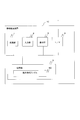
- FIG. 1 shows a configuration diagram of an information integration system.
- the system includes an information integration device 10, a shape (scalar) information measurement device 20, and a flow (vector) information measurement device 30.
- the information integration device 10 and the shape (scalar) information measurement device 20 and the flow (vector) information measurement device 30 may be connected via a wired or wireless appropriate network as shown in the figure. Alternatively, the connection may be made without going through a network. Further, the information integration device 10 is not connected to the shape (scalar) information measurement device 20 and the flow (vector) information measurement device 30, and is measured by the shape (scalar) information measurement device 20 and the flow (vector) information measurement device 30.
- the information may be input in advance and stored inside.
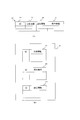
- FIG. 2 shows a configuration diagram of the information integration apparatus.
- the information integration device 10 includes a processing unit 1, an input unit 2, a display unit 3, an interface unit (I / F) 4, and a storage unit 5.
- the I / F 4 is an interface for connecting the shape (scalar) information measuring device 20 and the flow (vector) information measuring device 30 and inputting a shape (scalar) information image and a flow (vector) information image, respectively.
- the storage unit 5 includes an integrated information file 50.
- FIG. 3 is an explanatory diagram of the data format of the integrated information file.
- FIG. 3A shows a first example of the integrated information file 50.
- the integrated information file 50 stores, for each identification information (ID) 51, shape (scalar) information 52, flow (vector) information 53, and integrated information 54 obtained by integrating both pieces of information.
- FIG. 3B shows a second example of the integrated information file 50.
- the integrated information file 50 stores the shape (scalar) information image, flow (vector) information image, and integrated information for each ID in separate files 55 to 57.
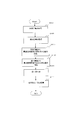
- FIG. 4 shows a flowchart of the information integration process.
- the information integration process when shape (scalar) information and flow (vector) information are acquired will be described below.
- the information integration process can target, for example, the shape of a tube or the like and the flow thereof, and can be integrated by utilizing the laminar flow flowing inside.
- the processing unit 1 inputs shape (scalar) information measured by the shape (scalar) information measuring device 20 via the I / F 4 and stores it in advance in the integrated information file 50 of the storage unit 5 for each ID. Can be.
- the processing unit 1 inputs the shape information image measured by the shape (scalar) information measuring device 20 via the I / F 4, obtains shape (scalar) information from the shape information image, and the like. 5 integrated information files 50 may be stored in advance for each ID. Further, the processing unit 1 inputs the flow (vector) information measured by the flow (vector) information measuring device 30 through the I / F 4 and stores it in advance in the integrated information file 50 of the storage unit 5 for each ID. Can be.
- the processing unit 1 inputs the flow information image measured by the flow (vector) information measuring device 30 via the I / F 4 and obtains the flow (vector) information from the flow information image by extraction or the like, and the storage unit 5 integrated information files 50 may be stored in advance for each ID. Note that the processing unit 1 may omit the ID and do not perform the processing for each ID when the number of objects is one, or is designated in advance (the same applies to the following processing).
- step S101 the processing unit 1 acquires shape (scalar) information stored in the integrated information file 50 of the storage unit 5 in accordance with the ID specified by the input unit 2 or the like.
- FIG. 5 is an explanatory diagram of shape (scalar) information.
- step S103 the processing unit 1 acquires the flow (vector) information stored in the integrated information file 50 of the storage unit 5 according to the ID specified by the input unit 2 or the like.
- FIG. 6 is an explanatory diagram of flow (vector) information.
- step S101 and / or S103 the shape (scalar) information and / or the flow (vector) information is not stored in the integrated information file 50 of the storage unit 5 in advance.
- a measurement image is input at an appropriate timing from the (scalar) information measuring device 20 and / or the flow (vector) information measuring device 30 and the shape (scalar) information and / or flow (vector) information is extracted from the input data. Or you may acquire.
- the processing unit 1 may extract or acquire shape (scalar) information and flow (vector) information from each input image, and store these information in the integrated information file 50 of the storage unit 5 for each ID.
- the processing unit 1 extracts the fastest candidate region or shape center line of the flow from the shape (scalar) information.
- the processing unit 1 can set the position of the center of gravity and the vicinity thereof in the cross section perpendicular or substantially perpendicular to the direction of the pipe or the like as the fastest candidate region as a region having a high flow velocity.
- the processing unit 1 for example, in shape information (scalar) such as luminance representing the shape of a tube or the like, the maximum luminance or the center of gravity or the like in a cross section perpendicular to or substantially perpendicular to the direction of the tube or the like May be acquired as the shape center line.
- the processing unit 1 may thin the shape (scalar) information and extract the center axis of the shape.
- the processing unit 1 may acquire the peripheral region with respect to the center of gravity position using various image processing methods such as a Gaussian filter.
- the processing unit 1 restricts the shape (scalar) information to a region near the center using data that is greater than or equal to a predetermined threshold value, data in a predetermined direction, and the like, and then flows from the shape (scalar) information.
- the fastest candidate region or shape center line may be extracted. Note that the reason why the fastest candidate area is used here is only that the fastest candidate area is assumed, and is not necessarily the fastest.
- the fastest candidate region or the shape center line can be appropriately represented by, for example, a line along the flow of the tube or the like, or a line-shaped region having a constant or non-constant width along the flow of the tube or the like.
- the processing unit 1 extracts the fastest region or the flow center line of the pipe flow from the flow (vector) information.
- the processing unit 1 can extract the fastest region as a set of regions in which the speed (vector norm value / size) change is small and the speed is locally maximum in a direction perpendicular to the flow direction.
- the processing unit 1 causes the magnitude (vector norm value) of the flow (vector) information at each position to flow at a position such as the maximum or the center of gravity in a cross section perpendicular to or substantially perpendicular to the direction of the tube or the like. You may acquire as a centerline.
- the processing unit 1 extracts the position where the velocity is maximum in the cross-sectional direction of the pipe or the like from the obtained flow (vector) information, and acquires the center line of the flow by connecting it to the flow direction. You may make it do.
- the processing unit 1 performs noise removal and information enhancement using various image processing methods such as smoothness constraint (the region obtained in the flow direction is continuous) and a Gaussian filter. Also good.
- the processing unit 1 limits the flow (vector) information to a region near the center by using data that is greater than or equal to a predetermined threshold, data in a predetermined direction, and the like, and then the flow from the flow (vector) information
- the fastest region or the flow center line may be extracted.
- the fastest region or the flow center line can be appropriately represented by, for example, a line along the flow of the tube or the like, or a line-shaped region having a constant or non-constant width along the flow of the tube or the like.
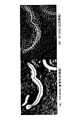
- FIG. 7 shows the fastest repair region or shape center line of shape (scalar) information.
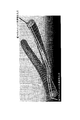
- FIG. 8 shows the fastest region or flow center line of flow (vector) information.
- the fastest repair region or the shape center line, the fastest region or the flow center line is represented by a line as an example, but may be represented by a mesh or other color or pattern in addition to the line.
- the processing unit 1 may or may not display these fastest repair region or shape center line, fastest region or flow center line on the display unit 5. Moreover, the process part 1 may memorize
- step S109 the processing unit 1 performs registration (registration) on the assumption that either the fastest candidate region or the shape center line obtained in step S105 matches the fastest region or the flow center line obtained in step S107.
- the processing unit 1 performs registration (registration) assuming that the fastest candidate area matches the fastest area.
- the processing unit 1 obtains the shape center line in step S105 and obtains the flow center line in step 107
- the processing unit 1 performs registration (registration) on the assumption that the shape center line matches the flow center line.
- alignment by the fastest candidate region and the flow center line, or alignment (registration) by the shape center line and the fastest region may be performed.
- the registration method may be, for example, an inter-shape registration method performed after shaping region information, an inter-image registration method performed using pixel information, or a combination thereof, or various registration processing methods / alignment processing methods. Can be used.
- the processing unit 1 may align the shape center line of the pipe or the like obtained in step S105 and the flow center line obtained in step S107 by an alignment process such as an iterative closest point method.
- the processing unit 1 further obtains the obtained relative position (relative position and orientation) as a relative position (relative position and orientation) between the shape (scalar) information and the flow (vector) information.
- step S111 the processing unit 1 performs registration (registration) using the relative position (relative position and orientation) obtained in step S109 by using visualization software or the like, thereby obtaining shape (scalar) information and flow (vector) information.
- integrated information is stored in the integrated information file 50 of the storage unit 5 for each ID, the integrated information file 50 of the storage unit 5 is referenced, and the integrated information is displayed on the display unit 3 To do.
- the processing unit 1 may display the shape (scalar) information and / or the flow (vector) information on the display unit 3 together with the integrated information.
- FIG. 9 is an explanatory diagram of the alignment process and the integrated information.
- FIG. 9A shows an example of a display image before alignment (an image obtained by superimposing shape (scalar) information and flow (vector) information)
- FIG. 9B shows a display image after alignment ( An example of an image of integrated information) is shown.
- the processing unit 1 can further acquire and form the shape (scalar) information, the flow (vector) information, and the integrated information of the above-described embodiment at predetermined time intervals. And the process part 1 memorize
- each information can be used in correspondence as follows.
- -Shape (scalar) information Various TOF-MRA (time-of-flight MR angiography), information acquired by 3D angiography, CT angiography, etc.-Information based on images, etc.
- -Flow (vector) information PC-MRA ( phase-contrast MR angiography), cerebral angiography, fluorescent angiography using indocyanine green, information based on acquired information / images by ultrasound, etc.
- the present invention and / or this embodiment can be applied to various fluid analyzes that can acquire both shape (scalar) information and flow (vector) information from an object (the same (measurement) object). it can.
- Blood vessel shape information and blood flow information are required for evaluation of vascular lesions, but there has been no technology that integrates a blood vessel information with a three-dimensional image of a blood vessel shape.
- blood vessels can obtain information from various medical image examinations. For example, time-of-flight magnetic resonance angiography (TOF-MRA) is used for blood vessel shape information, and phase-contrast magnetic resonance angiography (PC-MRA) is used for blood flow information.
- TOF-MRA time-of-flight magnetic resonance angiography
- PC-MRA phase-contrast magnetic resonance angiography
- the former is scalar information and the latter is a vector image with different dimensions.
- a blood flow simulation may be performed by modeling a blood vessel shape, but the shape and blood flow information using an actual medical image have not been integrated.
- the blood vessel shape information obtained by extracting the shape of the blood vessel from the measurement image obtained by the shape (scalar) information measuring apparatus 20 such as TOF-MRI, CT, and blood vessel imaging is used as the shape (scalar) information.
- blood flow information acquired from the flow (vector) information measuring device 30 such as PC-MRA is used as the flow (vector information).
- shape (scalar) information and flow (vector) information are both images of the same (same target) blood vessel.
- the fastest candidate region or shape center line of blood vessel shape information and the fastest region or flow center line of blood flow information are common by the processing unit 1, information on these fastest regions or center lines is obtained. Performs alignment between images under constraint conditions.
- the following processes 1) to 3) can be added and executed before the flowchart of FIG. 1)
- the shape (scalar) information measuring device 20 and the flow (vector) information measuring device 30 measure the patient's TOF-MRA, etc., PC-MRA, etc. as an example, and the processing unit 1 acquires these images.
- the processing unit 1 extracts blood vessel shape information from TOF-MRA or the like as shape (scalar) information, and stores it in the integrated information file 50 of the storage unit 5 for each patient ID.
- the processing unit 1 extracts blood flow information from PC-MRA or the like as flow (vector) information, and stores it in the integrated information file 50 of the storage unit 5 for each patient ID.
- the processing unit 1 can form, display, and / or store integrated information by executing each step using the acquired information according to the flowchart of FIG. 5 described above.
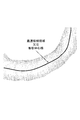
- FIG. 10A shows the fastest candidate region or shape center line of blood vessel shape (scalar) information
- FIG. 10B shows the fastest region or flow center line of blood flow (vector) information
- the fastest candidate area or shape center line and the fastest area or flow center line are represented by lines as an example.
- the processing unit 1 may display these on the display unit 5 or may not display them. Moreover, the process part 1 may memorize
- TOF-MRA and PC-MRA are displayed in an integrated manner, blood vessel shape (scalar) information and blood flow (vector) information can be presented in an integrated manner. It is expected that diagnosis of this will be possible more easily.
- this embodiment is used to evaluate the prognosis (bleeding risk during follow-up) in intracranial vascular lesions (unruptured cerebral aneurysms, cerebral arteriovenous malformations, etc.) It is expected to be applied to preoperative planning (determining the priority order for processing a large number of diseased blood vessels) such as cranioangioblastoma extraction and cranioclipping.
- An information integration method or an information integration apparatus / system of the present invention includes an information integration program for causing a computer to execute each procedure, a computer-readable recording medium recording the information integration program, and an internal memory of the computer including the information integration program Can be provided by a program product that can be loaded on the computer, a computer such as a server including the program, and the like.
Landscapes
- Health & Medical Sciences (AREA)
- Physics & Mathematics (AREA)
- Engineering & Computer Science (AREA)
- Life Sciences & Earth Sciences (AREA)
- Nuclear Medicine, Radiotherapy & Molecular Imaging (AREA)
- General Physics & Mathematics (AREA)
- Theoretical Computer Science (AREA)
- Animal Behavior & Ethology (AREA)
- Radiology & Medical Imaging (AREA)
- Biomedical Technology (AREA)
- Heart & Thoracic Surgery (AREA)
- Medical Informatics (AREA)
- Molecular Biology (AREA)
- Surgery (AREA)
- Biophysics (AREA)
- General Health & Medical Sciences (AREA)
- Public Health (AREA)
- Veterinary Medicine (AREA)
- Pathology (AREA)
- High Energy & Nuclear Physics (AREA)
- Computer Vision & Pattern Recognition (AREA)
- Geometry (AREA)
- Multimedia (AREA)
- Image Processing (AREA)
- Indicating Or Recording The Presence, Absence, Or Direction Of Movement (AREA)
- Aerodynamic Tests, Hydrodynamic Tests, Wind Tunnels, And Water Tanks (AREA)
- Magnetic Resonance Imaging Apparatus (AREA)
- Image Analysis (AREA)
Abstract
形状(スカラー)情報と流れ(ベクトル)情報とを統合して統合情報を求めること。 処理部が、記憶部又は他の装置から、同一対象についての形状(スカラー)情報及び流れ(ベクトル)情報を取得し(S101、S103)、形状(スカラー)情報から流れの最速候補領域又は形状中心線を抽出し(S105)、流れ(ベクトル)情報から管内流れの最速領域又は流れ中心線を抽出する(S107)。処理部が、抽出された最速候補領域又は形状中心線と、抽出された最速領域又は流れ中心線との位置合わせを行い、形状(スカラー)情報及び流れ(ベクトル)情報間の相対位置を求め(S109)、形状(スカラー)情報及び流れ(ベクトル)情報を、相対位置を用いて統合して統合情報を形成し、記憶部に記憶する及び/又は表示部に表示する(S111)。
Description
本発明は、情報統合方法及び装置及びシステム及びプログラムに係り、特に、形状(スカラー)情報と流れ(ベクトル)情報がそれぞれ取得された場合に、両情報を統合するための情報統合方法及び装置及びシステム及びプログラムに関する。
図11に、従来の流体解析の説明図を示す。
従来の数値流体力学(Computational Fluid Dynamics)は、主に、流体の運動に関する方程式をコンピュータで解くことによって流れを観察する数値解析・シミュレーション方法を用いていた。この場合、コンピュータに、全ての「入り口」と「出口」に流速を予め与え、その「あいだ」の流れをコンピュータで計算する。血流等の医用画像、航空機・自動車・風洞実験・水流など、ほとんどの流体解析は、このような方法が用いられている。
従来の数値流体力学(Computational Fluid Dynamics)は、主に、流体の運動に関する方程式をコンピュータで解くことによって流れを観察する数値解析・シミュレーション方法を用いていた。この場合、コンピュータに、全ての「入り口」と「出口」に流速を予め与え、その「あいだ」の流れをコンピュータで計算する。血流等の医用画像、航空機・自動車・風洞実験・水流など、ほとんどの流体解析は、このような方法が用いられている。
また、特許文献1には、「第1の画像データセットと第2の画像データセットとの間における位置合わせに関する第1の位置合わせと、第1の画像データセットと第2の画像データセットとの間の第1の位置合わせとは異なる位置合わせに関する第2の位置合わせとを実施する位置合わせユニットと、第1の位置合わせと第2の位置合わせとによる位置合わせの差に基づいて、第1の画像データセットと第2の画像データセットとの間の整合性度合いを判定する整合性判定ユニットと、を具備」し、「複数の医用画像の位置合わせにおいて、位置合わせの度合いを判定可能な医用画像処理装置」が開示されている(要約参照)。
従来の流体解析の場合、コンピュータには、通常、全ての「入り口」と「出口」に流速を予め与えなくてはならず、その「あいだ」の流れをコンピュータで計算しているだけであり、さらに「形状」がないと計算できない。また、通常、流れが途中で途切れていても、コンピュータは計算することができない。
また、従来より、形状をモデル化しシミュレーションを行う研究はなされているが、実際の画像を用いた形状(スカラー)情報と流れ(ベクトル)情報の統合は行われていない。
また、従来より、形状をモデル化しシミュレーションを行う研究はなされているが、実際の画像を用いた形状(スカラー)情報と流れ(ベクトル)情報の統合は行われていない。
本発明は、以上の点に鑑み、形状(スカラー)情報と流れ(ベクトル)情報とを統合して統合情報を求めることを目的とする。
本発明の第1の解決手段によると、
情報統合方法であって、
処理部が、記憶部又は他の装置から、同一対象についての形状若しくはスカラー情報及び流れ若しくはベクトル情報を取得し、
前記処理部が、前記形状若しくはスカラー情報から流れの最速候補領域又は形状中心線を抽出し、
前記処理部が、前記流れ若しくはベクトル情報から管内流れの最速領域又は流れ中心線を抽出し、
前記処理部が、抽出された前記最速候補領域又は前記形状中心線と、抽出された前記最速領域又は前記流れ中心線との位置合わせを行い、前記形状若しくはスカラー情報及び前記流れ若しくはベクトル情報間の相対位置を求め、
前記処理部が、前記形状若しくはスカラー情報及び前記流れ若しくはベクトル情報を、前記相対位置を用いて統合して統合情報を形成し、前記統合情報を前記記憶部に記憶する及び/又は表示部に表示する
情報統合方法が提供される。
情報統合方法であって、
処理部が、記憶部又は他の装置から、同一対象についての形状若しくはスカラー情報及び流れ若しくはベクトル情報を取得し、
前記処理部が、前記形状若しくはスカラー情報から流れの最速候補領域又は形状中心線を抽出し、
前記処理部が、前記流れ若しくはベクトル情報から管内流れの最速領域又は流れ中心線を抽出し、
前記処理部が、抽出された前記最速候補領域又は前記形状中心線と、抽出された前記最速領域又は前記流れ中心線との位置合わせを行い、前記形状若しくはスカラー情報及び前記流れ若しくはベクトル情報間の相対位置を求め、
前記処理部が、前記形状若しくはスカラー情報及び前記流れ若しくはベクトル情報を、前記相対位置を用いて統合して統合情報を形成し、前記統合情報を前記記憶部に記憶する及び/又は表示部に表示する
情報統合方法が提供される。
本発明の第2の解決手段によると、
情報統合装置であって、
形状若しくはスカラー情報及び流れ若しくはベクトル情報及びこれら両情報を統合した統合情報を記憶する記憶部と、
表示部と、
処理部と、
を備え、
前記処理部が、記憶部又は他の装置から、同一対象についての形状若しくはスカラー情報及び流れ若しくはベクトル情報を取得し、
前記処理部が、前記形状若しくはスカラー情報から流れの最速候補領域又は形状中心線を抽出し、
前記処理部が、前記流れ若しくはベクトル情報から管内流れの最速領域又は流れ中心線を抽出し、
前記処理部が、抽出された前記最速候補領域又は前記形状中心線と、抽出された前記最速領域又は前記流れ中心線との位置合わせを行い、前記形状若しくはスカラー情報及び前記流れ若しくはベクトル情報間の相対位置を求め、
前記処理部が、前記形状若しくはスカラー情報及び前記流れ若しくはベクトル情報を、前記相対位置を用いて統合して統合情報を形成し、前記統合情報を前記記憶部に記憶する及び/又は前記表示部に表示する
情報統合装置が提供される。
情報統合装置であって、
形状若しくはスカラー情報及び流れ若しくはベクトル情報及びこれら両情報を統合した統合情報を記憶する記憶部と、
表示部と、
処理部と、
を備え、
前記処理部が、記憶部又は他の装置から、同一対象についての形状若しくはスカラー情報及び流れ若しくはベクトル情報を取得し、
前記処理部が、前記形状若しくはスカラー情報から流れの最速候補領域又は形状中心線を抽出し、
前記処理部が、前記流れ若しくはベクトル情報から管内流れの最速領域又は流れ中心線を抽出し、
前記処理部が、抽出された前記最速候補領域又は前記形状中心線と、抽出された前記最速領域又は前記流れ中心線との位置合わせを行い、前記形状若しくはスカラー情報及び前記流れ若しくはベクトル情報間の相対位置を求め、
前記処理部が、前記形状若しくはスカラー情報及び前記流れ若しくはベクトル情報を、前記相対位置を用いて統合して統合情報を形成し、前記統合情報を前記記憶部に記憶する及び/又は前記表示部に表示する
情報統合装置が提供される。
本発明の第3の解決手段によると、
情報統合システムであって、
前記形状若しくはスカラー情報を測定する第1の測定装置と、
前記流れ若しくはベクトル情報を測定する第2の測定装置と
前記第1の測定装置及び前記第2の測定装置から、それぞれ前記形状若しくはスカラー情報及び前記流れ若しくはベクトル情報を入力する、上述のような情報統合装置と、
を備えた情報統合システムが提供される。
情報統合システムであって、
前記形状若しくはスカラー情報を測定する第1の測定装置と、
前記流れ若しくはベクトル情報を測定する第2の測定装置と
前記第1の測定装置及び前記第2の測定装置から、それぞれ前記形状若しくはスカラー情報及び前記流れ若しくはベクトル情報を入力する、上述のような情報統合装置と、
を備えた情報統合システムが提供される。
本発明の第4の解決手段によると、
情報統合プログラムであって、
処理部が、記憶部又は他の装置から、同一対象についての形状若しくはスカラー情報及び流れ若しくはベクトル情報を取得するステップと、
前記処理部が、前記形状若しくはスカラー情報から流れの最速候補領域又は形状中心線を抽出するステップと、
前記処理部が、前記流れ若しくはベクトル情報から管内流れの最速領域又は流れ中心線を抽出するステップと、
前記処理部が、抽出された前記最速候補領域又は前記形状中心線と、抽出された前記最速領域又は前記流れ中心線との位置合わせを行い、前記形状若しくはスカラー情報及び前記流れ若しくはベクトル情報間の相対位置を求めるステップと、
前記処理部が、前記形状若しくはスカラー情報及び前記流れ若しくはベクトル情報を、前記相対位置を用いて統合して統合情報を形成し、前記統合情報を前記記憶部に記憶する及び/又は表示部に表示するステップと
をコンピュータに実行させるための情報統合プログラムが提供される。
情報統合プログラムであって、
処理部が、記憶部又は他の装置から、同一対象についての形状若しくはスカラー情報及び流れ若しくはベクトル情報を取得するステップと、
前記処理部が、前記形状若しくはスカラー情報から流れの最速候補領域又は形状中心線を抽出するステップと、
前記処理部が、前記流れ若しくはベクトル情報から管内流れの最速領域又は流れ中心線を抽出するステップと、
前記処理部が、抽出された前記最速候補領域又は前記形状中心線と、抽出された前記最速領域又は前記流れ中心線との位置合わせを行い、前記形状若しくはスカラー情報及び前記流れ若しくはベクトル情報間の相対位置を求めるステップと、
前記処理部が、前記形状若しくはスカラー情報及び前記流れ若しくはベクトル情報を、前記相対位置を用いて統合して統合情報を形成し、前記統合情報を前記記憶部に記憶する及び/又は表示部に表示するステップと
をコンピュータに実行させるための情報統合プログラムが提供される。
本発明によると、形状(スカラー)情報と流れ(ベクトル)情報とを統合して統合情報を求めることができる。
1.情報統合処理
図1に、情報統合システムの構成図を示す。
本システムは、情報統合装置10、形状(スカラー)情報測定装置20、流れ(ベクトル)情報測定装置30を備える。なお、情報統合装置10と、形状(スカラー)情報測定装置20及び流れ(ベクトル)情報測定装置30とは、図示のように、有線又は無線の適宜のネットワークを介して接続されるようにしてもよいし、ネットワークを介さないで接続されるようにしてもよい。また、情報統合装置10は、形状(スカラー)情報測定装置20及び流れ(ベクトル)情報測定装置30とは接続されず、形状(スカラー)情報測定装置20及び流れ(ベクトル)情報測定装置30が測定した情報を、予め入力し、内部に記憶しておいてもよい。
図1に、情報統合システムの構成図を示す。
本システムは、情報統合装置10、形状(スカラー)情報測定装置20、流れ(ベクトル)情報測定装置30を備える。なお、情報統合装置10と、形状(スカラー)情報測定装置20及び流れ(ベクトル)情報測定装置30とは、図示のように、有線又は無線の適宜のネットワークを介して接続されるようにしてもよいし、ネットワークを介さないで接続されるようにしてもよい。また、情報統合装置10は、形状(スカラー)情報測定装置20及び流れ(ベクトル)情報測定装置30とは接続されず、形状(スカラー)情報測定装置20及び流れ(ベクトル)情報測定装置30が測定した情報を、予め入力し、内部に記憶しておいてもよい。
図2に、情報統合装置の構成図を示す。
情報統合装置10は、処理部1、入力部2、表示部3、インタフェース部(I/F)4、記憶部5を備える。I/F4は、形状(スカラー)情報測定装置20及び流れ(ベクトル)情報測定装置30と接続し、それぞれ形状(スカラー)情報画像及び流れ(ベクトル)情報画像を入力するためのインタフェースである。記憶部5は、統合情報ファイル50を含む。
情報統合装置10は、処理部1、入力部2、表示部3、インタフェース部(I/F)4、記憶部5を備える。I/F4は、形状(スカラー)情報測定装置20及び流れ(ベクトル)情報測定装置30と接続し、それぞれ形状(スカラー)情報画像及び流れ(ベクトル)情報画像を入力するためのインタフェースである。記憶部5は、統合情報ファイル50を含む。
図3に、統合情報ファイルのデータフォーマットの説明図を示す。
図3(A)は統合情報ファイル50の第1の例を示す。
ここでは、統合情報ファイル50は、識別情報(ID)51毎に、形状(スカラー)情報52及び流れ(ベクトル)情報53及びこれら両情報を統合した統合情報54が記憶される。
図3(B)は統合情報ファイル50の第2の例を示す。統合情報ファイル50は、ID毎の形状(スカラー)情報画像及び流れ(ベクトル)情報画像及び統合情報を別々のファイル55~57に記憶する。
図3(A)は統合情報ファイル50の第1の例を示す。
ここでは、統合情報ファイル50は、識別情報(ID)51毎に、形状(スカラー)情報52及び流れ(ベクトル)情報53及びこれら両情報を統合した統合情報54が記憶される。
図3(B)は統合情報ファイル50の第2の例を示す。統合情報ファイル50は、ID毎の形状(スカラー)情報画像及び流れ(ベクトル)情報画像及び統合情報を別々のファイル55~57に記憶する。
図4に、情報統合処理のフローチャートを示す。
以下に、形状(スカラー)情報と流れ(ベクトル)情報がそれぞれ取得された場合の情報統合処理について説明する。情報統合処理は、具体的には、例えば管状等の形状およびその流れを対象とすることができ、内部を層流が流れていることを利用して統合することができる。
一例として、処理部1は、形状(スカラー)情報測定装置20が測定した形状(スカラー)情報をI/F4を介して入力して記憶部5の統合情報ファイル50にID毎に予め記憶しているものとすることができる。あるいは、処理部1は、形状(スカラー)情報測定装置20が測定した形状情報画像をI/F4を介して入力して、形状情報画像から形状(スカラー)情報を抽出等により得て、記憶部5の統合情報ファイル50にID毎に予め記憶しているものとすることができる。
また、処理部1は、流れ(ベクトル)情報測定装置30が測定した流れ(ベクトル)情報をI/F4を介して入力して記憶部5の統合情報ファイル50にID毎に予め記憶しているものとすることができる。あるいは、処理部1は、流れ(ベクトル)情報測定装置30が測定した流れ情報画像をI/F4を介して入力して、流れ情報画像から流れ(ベクトル)情報を抽出等により得て、記憶部5の統合情報ファイル50にID毎に予め記憶しているものとすることができる。
なお、処理部1は、対象がひとつであったり、予め指定されている等の場合は、IDを省略し、ID毎に処理しなくてもよい(以下の処理において同様)。
以下に、形状(スカラー)情報と流れ(ベクトル)情報がそれぞれ取得された場合の情報統合処理について説明する。情報統合処理は、具体的には、例えば管状等の形状およびその流れを対象とすることができ、内部を層流が流れていることを利用して統合することができる。
一例として、処理部1は、形状(スカラー)情報測定装置20が測定した形状(スカラー)情報をI/F4を介して入力して記憶部5の統合情報ファイル50にID毎に予め記憶しているものとすることができる。あるいは、処理部1は、形状(スカラー)情報測定装置20が測定した形状情報画像をI/F4を介して入力して、形状情報画像から形状(スカラー)情報を抽出等により得て、記憶部5の統合情報ファイル50にID毎に予め記憶しているものとすることができる。
また、処理部1は、流れ(ベクトル)情報測定装置30が測定した流れ(ベクトル)情報をI/F4を介して入力して記憶部5の統合情報ファイル50にID毎に予め記憶しているものとすることができる。あるいは、処理部1は、流れ(ベクトル)情報測定装置30が測定した流れ情報画像をI/F4を介して入力して、流れ情報画像から流れ(ベクトル)情報を抽出等により得て、記憶部5の統合情報ファイル50にID毎に予め記憶しているものとすることができる。
なお、処理部1は、対象がひとつであったり、予め指定されている等の場合は、IDを省略し、ID毎に処理しなくてもよい(以下の処理において同様)。
以下に、手順を述べる。
ステップS101で、処理部1は、入力部2等により指定されたIDに従い、記憶部5の統合情報ファイル50に記憶されている形状(スカラー)情報を取得する。
図5に、形状(スカラー)情報の説明図を示す。
ステップS103で、処理部1は、入力部2等により指定されたIDに従い、記憶部5の統合情報ファイル50に記憶されている流れ(ベクトル)情報を取得する。
図6に、流れ(ベクトル)情報の説明図を示す。
なお、ステップS101及び/又はS103において、形状(スカラー)情報及び/又は流れ(ベクトル)情報が、記憶部5の統合情報ファイル50に予め記憶されていない場合など、記憶部5からではなく、形状(スカラー)情報測定装置20及び/又は流れ(ベクトル)情報測定装置30等から適宜のタイミングで測定画像を入力して、入力したデータから形状(スカラー)情報及び/又は流れ(ベクトル)情報を抽出又は取得してもよい。また、処理部1は、入力した各画像から形状(スカラー)情報及び流れ(ベクトル)情報を抽出又は取得し、これら情報をID毎に記憶部5の統合情報ファイル50に記憶してもよい。
ステップS101で、処理部1は、入力部2等により指定されたIDに従い、記憶部5の統合情報ファイル50に記憶されている形状(スカラー)情報を取得する。
図5に、形状(スカラー)情報の説明図を示す。
ステップS103で、処理部1は、入力部2等により指定されたIDに従い、記憶部5の統合情報ファイル50に記憶されている流れ(ベクトル)情報を取得する。
図6に、流れ(ベクトル)情報の説明図を示す。
なお、ステップS101及び/又はS103において、形状(スカラー)情報及び/又は流れ(ベクトル)情報が、記憶部5の統合情報ファイル50に予め記憶されていない場合など、記憶部5からではなく、形状(スカラー)情報測定装置20及び/又は流れ(ベクトル)情報測定装置30等から適宜のタイミングで測定画像を入力して、入力したデータから形状(スカラー)情報及び/又は流れ(ベクトル)情報を抽出又は取得してもよい。また、処理部1は、入力した各画像から形状(スカラー)情報及び流れ(ベクトル)情報を抽出又は取得し、これら情報をID毎に記憶部5の統合情報ファイル50に記憶してもよい。
ステップS105で、処理部1は、形状(スカラー)情報から流れの最速候補領域又は形状中心線を抽出する。例えば、処理部1は、管等の方向に対して垂直方向又は略垂直方向の断面における重心位置およびその周辺を流速の高い領域であるとして最速候補領域とすることができる。あるいは、処理部1は、例えば、管等の形状を表す輝度等の形状(スカラー)情報において、管等の方向に対して垂直方向又は略垂直方向の断面における最大輝度等又は輝度等の重心などを形状中心線として取得してもよい。また、処理部1は、形状(スカラー)情報を細線化処理し、形状の中心軸を抽出するようにしてもよい。なお、処理部1は、周辺領域を重心位置に対してガウスフィルターなど各種画像処理手法を用いて取得してもよい。また、処理部1は、形状(スカラー)情報を、予め定められた閾値以上のデータや予め定められた方向のデータ等により、中心付近の領域に限定した後に、形状(スカラー)情報から流れの最速候補領域又は形状中心線を抽出するようにしてもよい。
なお、ここで最速候補領域としている理由は,最速であると仮定しているだけであり、必ずしも最速とは限らないためである。また、最速候補領域又は形状中心線は、例えば、管等の流れに沿ったラインや、管等の流れに沿った幅が一定又は一定でないライン状の領域などで、適宜表すことができる。
なお、ここで最速候補領域としている理由は,最速であると仮定しているだけであり、必ずしも最速とは限らないためである。また、最速候補領域又は形状中心線は、例えば、管等の流れに沿ったラインや、管等の流れに沿った幅が一定又は一定でないライン状の領域などで、適宜表すことができる。
ステップS107で、処理部1は、流れ(ベクトル)情報から管内流れの最速領域又は流れ中心線を抽出する。例えば、処理部1が、最速領域を、流れ方向に対し垂直な方向において速度(ベクトルのノルム値・大きさ)変化が小さくかつ速度が局所的に最大となる領域の集合として抽出することができる。あるいは、処理部1は、各位置における流れ(ベクトル)情報の大きさ(ベクトルのノルム値)が、管等の方向に対して垂直方向又は略垂直方向の断面における最大又は重心等の位置を流れ中心線として取得してもよい。また、処理部1は、得られた流れ(ベクトル)情報に対し、管等の断面方向に対して速度が最大となる位置を抽出し、それを流れ方向につなげることで流れの中心線を取得するようにしてもよい。なお、この時、処理部1は、滑らかさ拘束(流れ方向に対して得られた領域が連続していること)やガウスフィルターなど各種画像処理手法を用いてノイズ除去や情報の強調を行っても良い。また、処理部1は、流れ(ベクトル)情報を、予め定められた閾値以上のデータや予め定められた方向のデータ等により、中心付近の領域に限定した後に、流れ(ベクトル)情報から管内流れの最速領域又は流れ中心線を抽出するようにしてもよい。なお、最速領域又は流れ中心線は、例えば、管等の流れに沿ったラインや、管等の流れに沿った幅が一定又は一定でないライン状の領域などで、適宜表すことができる。
図7に、形状(スカラー)情報の最速修補領域又は形状中心線を示す。
また、図8に、流れ(ベクトル)情報の最速領域又は流れ中心線を示す。
ここでは、最速修補領域又は形状中心線、最速領域又は流れ中心線を、一例として線で表しているが、線以外にもメッシュや他のカラー又は模様等で表してもよい。処理部1は、これら最速修補領域又は形状中心線、最速領域又は流れ中心線を表示部5に表示してもよいし、表示しなくてもよい。また、処理部1は、これら情報を記憶部5に記憶してもよいし、記憶しなくてもよい。
また、図8に、流れ(ベクトル)情報の最速領域又は流れ中心線を示す。
ここでは、最速修補領域又は形状中心線、最速領域又は流れ中心線を、一例として線で表しているが、線以外にもメッシュや他のカラー又は模様等で表してもよい。処理部1は、これら最速修補領域又は形状中心線、最速領域又は流れ中心線を表示部5に表示してもよいし、表示しなくてもよい。また、処理部1は、これら情報を記憶部5に記憶してもよいし、記憶しなくてもよい。
ステップS109で、処理部1は、ステップS105で得られた最速候補領域又は形状中心線のいずれかと、ステップS107で得られた最速領域又は流れ中心線とが一致するとして位置合わせ(レジストレーション)を行う。例えば、処理部1は、ステップS105で最速候補領域を得て、ステップS107で最速領域を得た場合、最速候補領域と最速領域とが一致するとして位置合わせ(レジストレーション)を行う。あるいは、処理部1は、ステップS105で形状中心線を得て、ステップ107で流れ中心線を得た場合、形状中心線と流れ中心線とが一致するとして位置合わせ(レジストレーション)を行う。あるいは、最速候補領域と流れ中心線とによる位置合わせ、又は、形状中心線と最速領域とによる位置合わせ(レジストレーション)を行ってもよい。位置合わせ手法は、例えば、領域情報を形状化した後に行う形状間レジストレーション法や画素情報を用いて行う画像間レジストレーション法やその組み合わせを用いたり、各種のレジストレーション処理方法・位置合わせ処理方法を用いることができる。また、処理部1は、ステップS105で得られた管等の形状中心線と、ステップS107で得られた流れ中心線をIterative closest point法等の位置合わせ処理により位置合わせするようにしてもよい。
また、ステップS109で、さらに、処理部1は、得られた相対位置(相対位置姿勢)を、形状(スカラー)情報および流れ(ベクトル)情報間の相対位置(相対位置姿勢)として求める。
また、ステップS109で、さらに、処理部1は、得られた相対位置(相対位置姿勢)を、形状(スカラー)情報および流れ(ベクトル)情報間の相対位置(相対位置姿勢)として求める。
ステップS111で、処理部1は、可視化ソフトウェア等により、ステップS109で得られた相対位置(相対位置姿勢)を用いて位置合わせ(レジストレーション)することで形状(スカラー)情報および流れ(ベクトル)情報を統合処理して統合情報を形成し、記憶部5の統合情報ファイル50に、ID毎に統合情報を記憶し、記憶部5の統合情報ファイル50を参照し、表示部3に統合情報を表示する。なお、処理部1は、形状(スカラー)情報及び/又は流れ(ベクトル)情報を、統合情報と共に表示部3に表示するようにしてもよい。
図9に、位置合わせ処理及び統合情報の説明図を示す。
図9(A)は、位置合わせ前の表示画像(形状(スカラー)情報と流れ(ベクトル)情報とを重ねた画像)の一例を示し、図9(B)は、位置合わせ後の表示画像(統合情報の画像)の一例を示す。
図9に、位置合わせ処理及び統合情報の説明図を示す。
図9(A)は、位置合わせ前の表示画像(形状(スカラー)情報と流れ(ベクトル)情報とを重ねた画像)の一例を示し、図9(B)は、位置合わせ後の表示画像(統合情報の画像)の一例を示す。
(時間変化への応用)
処理部1は、さらに、上述の実施形態の、形状(スカラー)情報、流れ(ベクトル)情報、及び、統合情報を、予め定められた時間間隔ごとに取得及び形成することができる。そして、処理部1は、これら情報を、ID毎に記憶部5の統合情報ファイル50に記憶し、また、表示部3に時間変化を動画により表示したり、複数の連続する静止画で表示することができる。
処理部1は、さらに、上述の実施形態の、形状(スカラー)情報、流れ(ベクトル)情報、及び、統合情報を、予め定められた時間間隔ごとに取得及び形成することができる。そして、処理部1は、これら情報を、ID毎に記憶部5の統合情報ファイル50に記憶し、また、表示部3に時間変化を動画により表示したり、複数の連続する静止画で表示することができる。
(適用例)
本発明及び/又は本実施の形態は、例えば、以下のように各情報を対応させて通用することができる。
・形状(スカラー)情報:各種TOF-MRA(time-of-flight MR angiography)、3次元血管撮影、CTアンギオグラフィーなどによる取得情報・画像等に基づく情報
・流れ(ベクトル)情報:PC-MRA(phase-contrast MR angiography)、脳血管撮影、インドシアニングリーンを用いた蛍光血管撮影、超音波などによる取得情報・画像等に基づく情報
本発明及び/又は本実施の形態は、例えば、以下のように各情報を対応させて通用することができる。
・形状(スカラー)情報:各種TOF-MRA(time-of-flight MR angiography)、3次元血管撮影、CTアンギオグラフィーなどによる取得情報・画像等に基づく情報
・流れ(ベクトル)情報:PC-MRA(phase-contrast MR angiography)、脳血管撮影、インドシアニングリーンを用いた蛍光血管撮影、超音波などによる取得情報・画像等に基づく情報
また、血管・血流、リンパ等の医用画像、航空機・ロケット・自動車・船等、風洞・水流・潮流、地球・宇宙・タイムマシン(時空転移装置等)などの物理学など、ひとつの(測定)対象(同一(測定)対象)から形状(スカラー)情報と流れ(ベクトル)情報の両情報を取得することができる様々な流体解析に、本発明及び/又は本実施の形態を適用することができる。
2.血管形状情報と血流情報のへの適用
以下に、一例として、血管形状(スカラー)と血流情報(ベクトル)を統合表示することで多次元診断を行う場合ついて説明する。
以下に、一例として、血管形状(スカラー)と血流情報(ベクトル)を統合表示することで多次元診断を行う場合ついて説明する。
脳神経外科領域では、医用画像の評価に基づく頭蓋内血管病変の手術適応の判断や治療計画の立案は重要なプロセスであり、血管の病変診断にも使用されてきた。血管病変の評価には血管形状情報と血流情報が必要であるが、血管の形状の3次元画像と血流情報を統合する技術が従来は存在しなかった。
また、血管は様々な医用画像検査から情報が得られる。例えば血管形状情報にはtime-of-flight magnetic resonance angiography(TOF-MRA)を、血流情報にはphase-contrast magnetic resonance angiography(PC-MRA)が用いられる。前者はスカラー情報であり後者はベクトル画像であり次元が異なる。そのため形状情報と血流情報を統合し診断を行うためには、異なる次元間の位置合わせ手法を提案する必要がある。従来、例えば、血管形状をモデル化して血流シミュレーションを行う研究はなされているかもしれないが、実際の医用画像を用いた形状と血流情報の統合は行われていない。
また、血管は様々な医用画像検査から情報が得られる。例えば血管形状情報にはtime-of-flight magnetic resonance angiography(TOF-MRA)を、血流情報にはphase-contrast magnetic resonance angiography(PC-MRA)が用いられる。前者はスカラー情報であり後者はベクトル画像であり次元が異なる。そのため形状情報と血流情報を統合し診断を行うためには、異なる次元間の位置合わせ手法を提案する必要がある。従来、例えば、血管形状をモデル化して血流シミュレーションを行う研究はなされているかもしれないが、実際の医用画像を用いた形状と血流情報の統合は行われていない。
そこで、本実施の形態では、TOF-MRI、CT、血管撮影などの形状(スカラー)情報測定装置20による測定画像から血管の形状を抽出して得られる血管形状情報を、形状(スカラー)情報として用いる。また、PC-MRAなどの流れ(ベクトル)情報測定装置30から取得される血流情報を、流れ(ベクトル情報)として用いる。これら形状(スカラー)情報と流れ(ベクトル)情報は、両者ともに同一(同一対象)の血管を撮影したものである。
本実施の形態によると、従来不可能であった、血管形状情報(スカラー情報)と血流情報(ベクトル情報)の統合法を提供することができる。
ここでは、一例として、処理部1により、血管形状情報の最速候補領域又は形状中心線と、血流情報の最速領域又は流れ中心線は共通するという仮定において、これら最速領域又は中心線に関する情報を拘束条件にした画像間位置合わせを行う。
本実施の形態によると、従来不可能であった、血管形状情報(スカラー情報)と血流情報(ベクトル情報)の統合法を提供することができる。
ここでは、一例として、処理部1により、血管形状情報の最速候補領域又は形状中心線と、血流情報の最速領域又は流れ中心線は共通するという仮定において、これら最速領域又は中心線に関する情報を拘束条件にした画像間位置合わせを行う。
この場合、例えば、図5のフローチャートの前段に、次のような処理1)~3)を追加して実行することができる。
1) まず、形状(スカラー)情報測定装置20及び流れ(ベクトル)情報測定装置30は、一例として患者のTOF-MRA等およびPC-MRA等を測定し、処理部1は、これら両画像を取得する。
2) 処理部1は、形状(スカラー)情報として、TOF-MRA等から血管形状情報を抽出し、それを記憶部5の統合情報ファイル50に患者のID毎に記憶する。
3) 処理部1は、流れ(ベクトル)情報として、PC-MRA等から血流情報を抽出し、それを記憶部5の統合情報ファイル50に患者のID毎に記憶する。
4) 処理部1は、取得されたこれら情報を用いて、上述の図5のフローチャートに従い、各ステップを実行することで、統合情報を形成し、表示及び/又は記憶することができる。
1) まず、形状(スカラー)情報測定装置20及び流れ(ベクトル)情報測定装置30は、一例として患者のTOF-MRA等およびPC-MRA等を測定し、処理部1は、これら両画像を取得する。
2) 処理部1は、形状(スカラー)情報として、TOF-MRA等から血管形状情報を抽出し、それを記憶部5の統合情報ファイル50に患者のID毎に記憶する。
3) 処理部1は、流れ(ベクトル)情報として、PC-MRA等から血流情報を抽出し、それを記憶部5の統合情報ファイル50に患者のID毎に記憶する。
4) 処理部1は、取得されたこれら情報を用いて、上述の図5のフローチャートに従い、各ステップを実行することで、統合情報を形成し、表示及び/又は記憶することができる。
図10(A)に、血管形状(スカラー)情報の最速候補領域又は形状中心線、図10(B)に、血流(ベクトル)情報の最速領域又は流れ中心線を示す。
ここでは、最速候補領域又は形状中心線、最速領域又は流れ中心線を、一例として線で表している。処理部1は、これらを表示部5に表示してもよいし、表示しなくてもよい。また、処理部1は、これら情報を記憶部5に記憶してもよいし、記憶しなくてもよい。
処理部1は、最速候補領域又は形状中心線と、最速領域又は流れ中心線との位置合わせを実行する。
ここでは、最速候補領域又は形状中心線、最速領域又は流れ中心線を、一例として線で表している。処理部1は、これらを表示部5に表示してもよいし、表示しなくてもよい。また、処理部1は、これら情報を記憶部5に記憶してもよいし、記憶しなくてもよい。
処理部1は、最速候補領域又は形状中心線と、最速領域又は流れ中心線との位置合わせを実行する。
このように、本実施の形態によると、TOF-MRAとPC-MRAを統合表示することで、血管の形状(スカラー)情報と血液の流れ(ベクトル)情報を統合提示することができ、病変部の診断が一層容易に可能となることが期待される。また、本実施の形態は、頭蓋内血管病変(未破裂脳動脈瘤、脳動静脈奇形等)における予後(経過観察中の出血リスク)の評価や出血予防手術(開頭脳動静脈奇形摘出術、開頭血管芽細胞腫摘出術、開頭クリッピング術等)の術前計画(多数ある病変血管の処理する優先順の決定)に適用することが期待される。
本発明の情報統合方法又は情報統合装置・システムは、その各手順をコンピュータに実行させるための情報統合プログラム、情報統合プログラムを記録したコンピュータ読み取り可能な記録媒体、情報統合プログラムを含みコンピュータの内部メモリにロード可能なプログラム製品、そのプログラムを含むサーバ等のコンピュータ、等により提供されることができる。
10 情報統合装置
20 形状(スカラー)情報測定装置
30 流れ(ベクトル)情報測定装置
20 形状(スカラー)情報測定装置
30 流れ(ベクトル)情報測定装置
Claims (11)
- 情報統合方法であって、
処理部が、記憶部又は他の装置から、同一対象についての形状若しくはスカラー情報及び流れ若しくはベクトル情報を取得し、
前記処理部が、前記形状若しくはスカラー情報から流れの最速候補領域又は形状中心線を抽出し、
前記処理部が、前記流れ若しくはベクトル情報から管内流れの最速領域又は流れ中心線を抽出し、
前記処理部が、抽出された前記最速候補領域又は前記形状中心線と、抽出された前記最速領域又は前記流れ中心線との位置合わせを行い、前記形状若しくはスカラー情報及び前記流れ若しくはベクトル情報間の相対位置を求め、
前記処理部が、前記形状若しくはスカラー情報及び前記流れ若しくはベクトル情報を、前記相対位置を用いて統合して統合情報を形成し、前記統合情報を前記記憶部に記憶する及び/又は表示部に表示する
情報統合方法。
- 請求項1に記載の情報統合方法において、
前記処理部が、第1の測定装置が測定した前記形状若しくはスカラー情報又は前記第1の測定装置が測定した形状若しくはスカラー画像から得られる前記形状若しくはスカラー情報、及び、第2の測定装置が測定した前記流れ若しくはベクトル情報又は前記第2の測定装置が測定した流れ若しくはベクトル画像から得られる前記流れ若しくはベクトル情報を、前記記憶部に記憶することを特徴とする情報統合方法。
- 請求項1又は2に記載の情報統合方法において、
前記処理部が、前記形状若しくはスカラー情報及び/又は前記流れ若しくはベクトル情報を、予め定められた閾値又は方向に基づき限定した後に、前記形状若しくはスカラー情報から流れの最速候補領域又は形状中心線を抽出する、及び/又は、前記流れ若しくはベクトル情報から管内流れの最速領域又は流れ中心線を抽出することを特徴とする情報統合方法。
- 請求項1乃至3のいずれかに記載の情報統合方法において、
前記処理部が、さらに前記形状若しくはスカラー情報及び/又は前記流れ若しくはベクトル情報を、前記統合情報と共に前記表示部に表示することを特徴とする情報統合方法。
- 請求項1乃至4のいずれかに記載の情報統合方法において、
前記処理部が、さらに、前記形状若しくはスカラー情報、前記流れ若しくはベクトル情報、及び、前記統合情報を、予め定められた時間間隔ごとに取得及び形成し、これら情報を、前記記憶部に記憶し、及び/又は、前記表示部に時間変化を動画により表示又は複数の連続する静止画により表示することを特徴とする情報統合方法。
- 請求項1乃至5のいずれかに記載の情報統合方法において、
前記形状若しくはスカラー情報と前記流れ若しくはベクトル情報は、血管・血流、リンパ等の医用画像、航空機・ロケット・自動車・船等、風洞・水流・潮流、地球・宇宙・タイムマシン・その他の物理学のいずれかの技術分野で、同一対象から取得した情報であることを特徴とする情報統合方法。
- 請求項1乃至6のいずれかに記載の情報統合方法において、
前記形状若しくはスカラー情報は、各種TOF-MRA(time-of-flight MR angiography)、3次元血管撮影、CTアンギオグラフィーのいずれかによる取得情報又は画像に基づく情報であり、
前記流れ若しくはベクトル情報は、PC-MRA(phase-contrast MR angiography)、脳血管撮影、インドシアニングリーンを用いた蛍光血管撮影、超音波のいずれかによる取得情報又は画像に基づく情報である
ことを特徴とする情報統合方法。
- 請求項1乃至7のいずれかに記載の情報統合方法において、
前記形状若しくはスカラー情報と前記流れ若しくはベクトル情報は、それぞれ、血管形状情報と血流情報、又は、リンパ管形状とリンパ流情報であることを特徴とする情報統合方法。
- 情報統合装置であって、
形状若しくはスカラー情報及び流れ若しくはベクトル情報及びこれら両情報を統合した統合情報を記憶する記憶部と、
表示部と、
処理部と、
を備え、
前記処理部が、記憶部又は他の装置から、同一対象についての形状若しくはスカラー情報及び流れ若しくはベクトル情報を取得し、
前記処理部が、前記形状若しくはスカラー情報から流れの最速候補領域又は形状中心線を抽出し、
前記処理部が、前記流れ若しくはベクトル情報から管内流れの最速領域又は流れ中心線を抽出し、
前記処理部が、抽出された前記最速候補領域又は前記形状中心線と、抽出された前記最速領域又は前記流れ中心線との位置合わせを行い、前記形状若しくはスカラー情報及び前記流れ若しくはベクトル情報間の相対位置を求め、
前記処理部が、前記形状若しくはスカラー情報及び前記流れ若しくはベクトル情報を、前記相対位置を用いて統合して統合情報を形成し、前記統合情報を前記記憶部に記憶する及び/又は前記表示部に表示する
情報統合装置。
- 情報統合システムであって、
前記形状若しくはスカラー情報を測定する第1の測定装置と、
前記流れ若しくはベクトル情報を測定する第2の測定装置と
前記第1の測定装置及び前記第2の測定装置から、それぞれ前記形状若しくはスカラー情報及び前記流れ若しくはベクトル情報を入力する、請求項9に記載された情報統合装置と、
を備えた情報統合システム。
- 情報統合プログラムであって、
処理部が、記憶部又は他の装置から、同一対象についての形状若しくはスカラー情報及び流れ若しくはベクトル情報を取得するステップと、
前記処理部が、前記形状若しくはスカラー情報から流れの最速候補領域又は形状中心線を抽出するステップと、
前記処理部が、前記流れ若しくはベクトル情報から管内流れの最速領域又は流れ中心線を抽出するステップと、
前記処理部が、抽出された前記最速候補領域又は前記形状中心線と、抽出された前記最速領域又は前記流れ中心線との位置合わせを行い、前記形状若しくはスカラー情報及び前記流れ若しくはベクトル情報間の相対位置を求めるステップと、
前記処理部が、前記形状若しくはスカラー情報及び前記流れ若しくはベクトル情報を、前記相対位置を用いて統合して統合情報を形成し、前記統合情報を前記記憶部に記憶する及び/又は表示部に表示するステップと
をコンピュータに実行させるための情報統合プログラム。
Applications Claiming Priority (2)
| Application Number | Priority Date | Filing Date | Title |
|---|---|---|---|
| JP2015-076517 | 2015-04-03 | ||
| JP2015076517A JP6385876B2 (ja) | 2015-04-03 | 2015-04-03 | 情報統合方法及び装置及びシステム及びプログラム |
Publications (1)
| Publication Number | Publication Date |
|---|---|
| WO2016159353A1 true WO2016159353A1 (ja) | 2016-10-06 |
Family
ID=57005189
Family Applications (1)
| Application Number | Title | Priority Date | Filing Date |
|---|---|---|---|
| PCT/JP2016/060932 Ceased WO2016159353A1 (ja) | 2015-04-03 | 2016-04-01 | 情報統合方法及び装置及びシステム及びプログラム |
Country Status (2)
| Country | Link |
|---|---|
| JP (1) | JP6385876B2 (ja) |
| WO (1) | WO2016159353A1 (ja) |
Families Citing this family (2)
| Publication number | Priority date | Publication date | Assignee | Title |
|---|---|---|---|---|
| JP7102318B2 (ja) * | 2018-11-09 | 2022-07-19 | 国際航業株式会社 | 地下水流表示システム |
| WO2021084916A1 (ja) | 2019-10-28 | 2021-05-06 | 富士フイルム株式会社 | 領域同定装置、方法およびプログラム |
Citations (2)
| Publication number | Priority date | Publication date | Assignee | Title |
|---|---|---|---|---|
| JP2012115658A (ja) * | 2010-11-12 | 2012-06-21 | Toshiba Corp | 画像診断装置 |
| JP2014188323A (ja) * | 2013-03-28 | 2014-10-06 | Toshiba Corp | 血流解析装置及び血流解析プログラム |
Family Cites Families (1)
| Publication number | Priority date | Publication date | Assignee | Title |
|---|---|---|---|---|
| US9552533B2 (en) * | 2013-03-05 | 2017-01-24 | Toshiba Medical Systems Corporation | Image registration apparatus and method |
-
2015
- 2015-04-03 JP JP2015076517A patent/JP6385876B2/ja not_active Expired - Fee Related
-
2016
- 2016-04-01 WO PCT/JP2016/060932 patent/WO2016159353A1/ja not_active Ceased
Patent Citations (2)
| Publication number | Priority date | Publication date | Assignee | Title |
|---|---|---|---|---|
| JP2012115658A (ja) * | 2010-11-12 | 2012-06-21 | Toshiba Corp | 画像診断装置 |
| JP2014188323A (ja) * | 2013-03-28 | 2014-10-06 | Toshiba Corp | 血流解析装置及び血流解析プログラム |
Also Published As
| Publication number | Publication date |
|---|---|
| JP6385876B2 (ja) | 2018-09-05 |
| JP2016197042A (ja) | 2016-11-24 |
Similar Documents
| Publication | Publication Date | Title |
|---|---|---|
| JP7309986B2 (ja) | 医用画像処理方法、医用画像処理装置、医用画像処理システム及び医用画像処理プログラム | |
| US8050475B2 (en) | Detection and localization of vascular occlusion from angiography data | |
| CN102551780B (zh) | 用于确定和显示心肌的供血的装置和计算机断层造影仪 | |
| JP7053656B6 (ja) | 造影剤注入撮像 | |
| CN107067398B (zh) | 用于三维医学模型中缺失血管的补全方法及装置 | |
| US7889895B2 (en) | Method and apparatus for identifying pathology in brain images | |
| JP6162452B2 (ja) | 血流解析装置及び血流解析プログラム | |
| CN103917165A (zh) | 用于血流性状诊断的系统、其方法及计算机软件程序 | |
| US9345442B2 (en) | System and derivation method | |
| CN102781332B (zh) | 医用图像处理装置 | |
| Orczyk et al. | Preliminary experience with a novel method of three-dimensional co-registration of prostate cancer digital histology and in vivo multiparametric MRI | |
| JP2016047217A (ja) | 画像処理方法および装置並びにプログラム | |
| US10182782B2 (en) | Evaluation apparatus, evaluation method, and evaluation program | |
| JP6385876B2 (ja) | 情報統合方法及び装置及びシステム及びプログラム | |
| JP2016131836A (ja) | 血流プロファイルの測定方法 | |
| CN104936505A (zh) | 使用预先采集的图像进行的导航 | |
| KR20140120236A (ko) | 심근 및 심혈관 정보의 통합 분석 방법 | |
| KR101977294B1 (ko) | 전산유체역학을 이용한 기관지 분석 방법 및 그 장치 | |
| CN112488988B (zh) | 用于自动确定中空器官的变化的方法和装置 | |
| Zhang et al. | Morphological feature measurement of specific locations using image processing | |
| JP6554722B2 (ja) | 画像処理方法および装置並びにプログラム | |
| Iversen et al. | Automatic intraoperative estimation of blood flow direction during neurosurgical interventions | |
| Pisani et al. | Aortic Centerline Extraction in 4D-Flow MRI: Effect of Threshold Selection and Subsampling | |
| Subramanian et al. | Geometry-based metrics for planning of neuroendovascular therapy | |
| CN120689263A (zh) | 医学图像中的血管异常的ai辅助检测 |
Legal Events
| Date | Code | Title | Description |
|---|---|---|---|
| 121 | Ep: the epo has been informed by wipo that ep was designated in this application |
Ref document number: 16773233 Country of ref document: EP Kind code of ref document: A1 |
|
| NENP | Non-entry into the national phase |
Ref country code: DE |
|
| 122 | Ep: pct application non-entry in european phase |
Ref document number: 16773233 Country of ref document: EP Kind code of ref document: A1 |