WO2016159333A1 - Separation membrane - Google Patents
Separation membrane Download PDFInfo
- Publication number
- WO2016159333A1 WO2016159333A1 PCT/JP2016/060861 JP2016060861W WO2016159333A1 WO 2016159333 A1 WO2016159333 A1 WO 2016159333A1 JP 2016060861 W JP2016060861 W JP 2016060861W WO 2016159333 A1 WO2016159333 A1 WO 2016159333A1
- Authority
- WO
- WIPO (PCT)
- Prior art keywords
- separation membrane
- layer
- membrane
- length
- ratio
- Prior art date
Links
- 239000012528 membrane Substances 0.000 title claims abstract description 408
- 238000000926 separation method Methods 0.000 title claims abstract description 263
- 229920002678 cellulose Polymers 0.000 claims abstract description 70
- 239000012510 hollow fiber Substances 0.000 claims description 78
- 239000004952 Polyamide Substances 0.000 claims description 50
- 229920002647 polyamide Polymers 0.000 claims description 50
- 229920000728 polyester Polymers 0.000 claims description 46
- 239000011800 void material Substances 0.000 claims description 40
- 150000001875 compounds Chemical class 0.000 claims description 32
- -1 polyethylene terephthalate Polymers 0.000 claims description 17
- 229920002292 Nylon 6 Polymers 0.000 claims description 9
- 229920008347 Cellulose acetate propionate Polymers 0.000 claims description 7
- 230000001747 exhibiting effect Effects 0.000 claims description 7
- 229920002302 Nylon 6,6 Polymers 0.000 claims description 6
- 238000009292 forward osmosis Methods 0.000 claims description 6
- 229920000139 polyethylene terephthalate Polymers 0.000 claims description 6
- 239000005020 polyethylene terephthalate Substances 0.000 claims description 6
- 238000001223 reverse osmosis Methods 0.000 claims description 6
- 238000001728 nano-filtration Methods 0.000 claims description 5
- 229920006217 cellulose acetate butyrate Polymers 0.000 claims description 4
- 239000012461 cellulose resin Substances 0.000 abstract description 2
- 239000010410 layer Substances 0.000 description 137
- 239000011342 resin composition Substances 0.000 description 59
- XLYOFNOQVPJJNP-UHFFFAOYSA-N water Substances O XLYOFNOQVPJJNP-UHFFFAOYSA-N 0.000 description 50
- 239000000203 mixture Substances 0.000 description 48
- LYCAIKOWRPUZTN-UHFFFAOYSA-N Ethylene glycol Chemical compound OCCO LYCAIKOWRPUZTN-UHFFFAOYSA-N 0.000 description 40
- 239000000654 additive Substances 0.000 description 38
- 230000000996 additive effect Effects 0.000 description 37
- 239000002131 composite material Substances 0.000 description 31
- 238000005259 measurement Methods 0.000 description 30
- 238000002074 melt spinning Methods 0.000 description 30
- 239000004014 plasticizer Substances 0.000 description 29
- 238000001816 cooling Methods 0.000 description 27
- QTBSBXVTEAMEQO-UHFFFAOYSA-N Acetic acid Chemical compound CC(O)=O QTBSBXVTEAMEQO-UHFFFAOYSA-N 0.000 description 24
- 238000000034 method Methods 0.000 description 23
- 239000003963 antioxidant agent Substances 0.000 description 19
- 150000003839 salts Chemical class 0.000 description 19
- KFZMGEQAYNKOFK-UHFFFAOYSA-N Isopropanol Chemical compound CC(C)O KFZMGEQAYNKOFK-UHFFFAOYSA-N 0.000 description 18
- 230000003078 antioxidant effect Effects 0.000 description 18
- 238000004519 manufacturing process Methods 0.000 description 16
- 239000008188 pellet Substances 0.000 description 16
- 239000011148 porous material Substances 0.000 description 16
- 230000004907 flux Effects 0.000 description 15
- 230000000704 physical effect Effects 0.000 description 15
- 239000002994 raw material Substances 0.000 description 15
- 239000007864 aqueous solution Substances 0.000 description 14
- 238000009987 spinning Methods 0.000 description 14
- SECXISVLQFMRJM-UHFFFAOYSA-N N-Methylpyrrolidone Chemical compound CN1CCCC1=O SECXISVLQFMRJM-UHFFFAOYSA-N 0.000 description 13
- 230000000052 comparative effect Effects 0.000 description 13
- 239000002904 solvent Substances 0.000 description 13
- 238000006467 substitution reaction Methods 0.000 description 13
- 239000002202 Polyethylene glycol Substances 0.000 description 12
- 239000000805 composite resin Substances 0.000 description 12
- 238000002844 melting Methods 0.000 description 12
- 230000008018 melting Effects 0.000 description 12
- 229920001223 polyethylene glycol Polymers 0.000 description 12
- 239000001913 cellulose Substances 0.000 description 11
- 230000035699 permeability Effects 0.000 description 11
- 239000000523 sample Substances 0.000 description 11
- 239000007789 gas Substances 0.000 description 10
- 239000011347 resin Substances 0.000 description 10
- 229920005989 resin Polymers 0.000 description 10
- 238000006243 chemical reaction Methods 0.000 description 9
- 238000006068 polycondensation reaction Methods 0.000 description 9
- 229920000642 polymer Polymers 0.000 description 9
- 239000000243 solution Substances 0.000 description 9
- 125000002777 acetyl group Chemical group [H]C([H])([H])C(*)=O 0.000 description 8
- 125000002252 acyl group Chemical group 0.000 description 8
- 229920002301 cellulose acetate Polymers 0.000 description 8
- 125000003827 glycol group Chemical group 0.000 description 8
- 230000001965 increasing effect Effects 0.000 description 8
- QAOWNCQODCNURD-UHFFFAOYSA-N Sulfuric acid Chemical compound OS(O)(=O)=O QAOWNCQODCNURD-UHFFFAOYSA-N 0.000 description 7
- 230000000694 effects Effects 0.000 description 7
- 229920001515 polyalkylene glycol Polymers 0.000 description 7
- WFDIJRYMOXRFFG-UHFFFAOYSA-N Acetic anhydride Chemical compound CC(=O)OC(C)=O WFDIJRYMOXRFFG-UHFFFAOYSA-N 0.000 description 6
- CSCPPACGZOOCGX-UHFFFAOYSA-N Acetone Chemical compound CC(C)=O CSCPPACGZOOCGX-UHFFFAOYSA-N 0.000 description 6
- LFQSCWFLJHTTHZ-UHFFFAOYSA-N Ethanol Chemical compound CCO LFQSCWFLJHTTHZ-UHFFFAOYSA-N 0.000 description 6
- OKKJLVBELUTLKV-UHFFFAOYSA-N Methanol Chemical compound OC OKKJLVBELUTLKV-UHFFFAOYSA-N 0.000 description 6
- FAPWRFPIFSIZLT-UHFFFAOYSA-M Sodium chloride Chemical compound [Na+].[Cl-] FAPWRFPIFSIZLT-UHFFFAOYSA-M 0.000 description 6
- 238000009833 condensation Methods 0.000 description 6
- 230000005494 condensation Effects 0.000 description 6
- 239000013078 crystal Substances 0.000 description 6
- 125000001142 dicarboxylic acid group Chemical group 0.000 description 6
- 150000002148 esters Chemical class 0.000 description 6
- 239000000155 melt Substances 0.000 description 6
- 239000002243 precursor Substances 0.000 description 6
- 238000003756 stirring Methods 0.000 description 6
- 238000010438 heat treatment Methods 0.000 description 5
- 238000007654 immersion Methods 0.000 description 5
- 238000004898 kneading Methods 0.000 description 5
- IJGRMHOSHXDMSA-UHFFFAOYSA-N Atomic nitrogen Chemical compound N#N IJGRMHOSHXDMSA-UHFFFAOYSA-N 0.000 description 4
- PEDCQBHIVMGVHV-UHFFFAOYSA-N Glycerine Chemical compound OCC(O)CO PEDCQBHIVMGVHV-UHFFFAOYSA-N 0.000 description 4
- CDBYLPFSWZWCQE-UHFFFAOYSA-L Sodium Carbonate Chemical compound [Na+].[Na+].[O-]C([O-])=O CDBYLPFSWZWCQE-UHFFFAOYSA-L 0.000 description 4
- KKEYFWRCBNTPAC-UHFFFAOYSA-N Terephthalic acid Chemical compound OC(=O)C1=CC=C(C(O)=O)C=C1 KKEYFWRCBNTPAC-UHFFFAOYSA-N 0.000 description 4
- GWEVSGVZZGPLCZ-UHFFFAOYSA-N Titan oxide Chemical compound O=[Ti]=O GWEVSGVZZGPLCZ-UHFFFAOYSA-N 0.000 description 4
- ADCOVFLJGNWWNZ-UHFFFAOYSA-N antimony trioxide Chemical compound O=[Sb]O[Sb]=O ADCOVFLJGNWWNZ-UHFFFAOYSA-N 0.000 description 4
- WPYMKLBDIGXBTP-UHFFFAOYSA-N benzoic acid Chemical compound OC(=O)C1=CC=CC=C1 WPYMKLBDIGXBTP-UHFFFAOYSA-N 0.000 description 4
- 238000004364 calculation method Methods 0.000 description 4
- 239000003795 chemical substances by application Substances 0.000 description 4
- 229920001577 copolymer Polymers 0.000 description 4
- WOZVHXUHUFLZGK-UHFFFAOYSA-N dimethyl terephthalate Chemical compound COC(=O)C1=CC=C(C(=O)OC)C=C1 WOZVHXUHUFLZGK-UHFFFAOYSA-N 0.000 description 4
- JBKVHLHDHHXQEQ-UHFFFAOYSA-N epsilon-caprolactam Chemical compound O=C1CCCCCN1 JBKVHLHDHHXQEQ-UHFFFAOYSA-N 0.000 description 4
- WGCNASOHLSPBMP-UHFFFAOYSA-N hydroxyacetaldehyde Natural products OCC=O WGCNASOHLSPBMP-UHFFFAOYSA-N 0.000 description 4
- QQVIHTHCMHWDBS-UHFFFAOYSA-N isophthalic acid Chemical compound OC(=O)C1=CC=CC(C(O)=O)=C1 QQVIHTHCMHWDBS-UHFFFAOYSA-N 0.000 description 4
- 238000002156 mixing Methods 0.000 description 4
- 150000007524 organic acids Chemical group 0.000 description 4
- 239000002245 particle Substances 0.000 description 4
- 238000005979 thermal decomposition reaction Methods 0.000 description 4
- OGIDPMRJRNCKJF-UHFFFAOYSA-N titanium oxide Inorganic materials [Ti]=O OGIDPMRJRNCKJF-UHFFFAOYSA-N 0.000 description 4
- 238000004804 winding Methods 0.000 description 4
- OKOBUGCCXMIKDM-UHFFFAOYSA-N Irganox 1098 Chemical compound CC(C)(C)C1=C(O)C(C(C)(C)C)=CC(CCC(=O)NCCCCCCNC(=O)CCC=2C=C(C(O)=C(C=2)C(C)(C)C)C(C)(C)C)=C1 OKOBUGCCXMIKDM-UHFFFAOYSA-N 0.000 description 3
- FDBMBOYIVUGUSL-UHFFFAOYSA-N OP(O)OP(O)O.C(C)(C)(C)C1=C(C(=CC(=C1)C)C(C)(C)C)C(O)(C(CO)(CO)CO)C1=C(C=C(C=C1C(C)(C)C)C)C(C)(C)C Chemical compound OP(O)OP(O)O.C(C)(C)(C)C1=C(C(=CC(=C1)C)C(C)(C)C)C(O)(C(CO)(CO)CO)C1=C(C=C(C=C1C(C)(C)C)C)C(C)(C)C FDBMBOYIVUGUSL-UHFFFAOYSA-N 0.000 description 3
- HEMHJVSKTPXQMS-UHFFFAOYSA-M Sodium hydroxide Chemical compound [OH-].[Na+] HEMHJVSKTPXQMS-UHFFFAOYSA-M 0.000 description 3
- 239000002253 acid Substances 0.000 description 3
- 238000004458 analytical method Methods 0.000 description 3
- 125000004432 carbon atom Chemical group C* 0.000 description 3
- 230000008859 change Effects 0.000 description 3
- 229940105990 diglycerin Drugs 0.000 description 3
- GPLRAVKSCUXZTP-UHFFFAOYSA-N diglycerol Chemical compound OCC(O)COCC(O)CO GPLRAVKSCUXZTP-UHFFFAOYSA-N 0.000 description 3
- 238000005886 esterification reaction Methods 0.000 description 3
- 238000001125 extrusion Methods 0.000 description 3
- 150000002334 glycols Chemical class 0.000 description 3
- 238000005374 membrane filtration Methods 0.000 description 3
- 239000011259 mixed solution Substances 0.000 description 3
- 229940049964 oleate Drugs 0.000 description 3
- ZQPPMHVWECSIRJ-KTKRTIGZSA-N oleic acid Chemical compound CCCCCCCC\C=C/CCCCCCCC(O)=O ZQPPMHVWECSIRJ-KTKRTIGZSA-N 0.000 description 3
- 239000011780 sodium chloride Substances 0.000 description 3
- 239000000126 substance Substances 0.000 description 3
- 230000008961 swelling Effects 0.000 description 3
- 238000004448 titration Methods 0.000 description 3
- ARCGXLSVLAOJQL-UHFFFAOYSA-N trimellitic acid Chemical compound OC(=O)C1=CC=C(C(O)=O)C(C(O)=O)=C1 ARCGXLSVLAOJQL-UHFFFAOYSA-N 0.000 description 3
- 230000000007 visual effect Effects 0.000 description 3
- 238000005406 washing Methods 0.000 description 3
- PUPZLCDOIYMWBV-UHFFFAOYSA-N (+/-)-1,3-Butanediol Chemical compound CC(O)CCO PUPZLCDOIYMWBV-UHFFFAOYSA-N 0.000 description 2
- 239000005711 Benzoic acid Substances 0.000 description 2
- CURLTUGMZLYLDI-UHFFFAOYSA-N Carbon dioxide Chemical compound O=C=O CURLTUGMZLYLDI-UHFFFAOYSA-N 0.000 description 2
- ZAMOUSCENKQFHK-UHFFFAOYSA-N Chlorine atom Chemical compound [Cl] ZAMOUSCENKQFHK-UHFFFAOYSA-N 0.000 description 2
- IAZDPXIOMUYVGZ-UHFFFAOYSA-N Dimethylsulphoxide Chemical compound CS(C)=O IAZDPXIOMUYVGZ-UHFFFAOYSA-N 0.000 description 2
- FYYHWMGAXLPEAU-UHFFFAOYSA-N Magnesium Chemical group [Mg] FYYHWMGAXLPEAU-UHFFFAOYSA-N 0.000 description 2
- 229920000572 Nylon 6/12 Polymers 0.000 description 2
- ISWSIDIOOBJBQZ-UHFFFAOYSA-N Phenol Chemical compound OC1=CC=CC=C1 ISWSIDIOOBJBQZ-UHFFFAOYSA-N 0.000 description 2
- OAICVXFJPJFONN-UHFFFAOYSA-N Phosphorus Chemical compound [P] OAICVXFJPJFONN-UHFFFAOYSA-N 0.000 description 2
- DNIAPMSPPWPWGF-UHFFFAOYSA-N Propylene glycol Chemical compound CC(O)CO DNIAPMSPPWPWGF-UHFFFAOYSA-N 0.000 description 2
- XUIMIQQOPSSXEZ-UHFFFAOYSA-N Silicon Chemical compound [Si] XUIMIQQOPSSXEZ-UHFFFAOYSA-N 0.000 description 2
- WYURNTSHIVDZCO-UHFFFAOYSA-N Tetrahydrofuran Chemical compound C1CCOC1 WYURNTSHIVDZCO-UHFFFAOYSA-N 0.000 description 2
- 239000006096 absorbing agent Substances 0.000 description 2
- WNLRTRBMVRJNCN-UHFFFAOYSA-N adipic acid Chemical compound OC(=O)CCCCC(O)=O WNLRTRBMVRJNCN-UHFFFAOYSA-N 0.000 description 2
- 239000003513 alkali Substances 0.000 description 2
- WATWJIUSRGPENY-UHFFFAOYSA-N antimony atom Chemical group [Sb] WATWJIUSRGPENY-UHFFFAOYSA-N 0.000 description 2
- 239000002216 antistatic agent Substances 0.000 description 2
- QMKYBPDZANOJGF-UHFFFAOYSA-N benzene-1,3,5-tricarboxylic acid Chemical compound OC(=O)C1=CC(C(O)=O)=CC(C(O)=O)=C1 QMKYBPDZANOJGF-UHFFFAOYSA-N 0.000 description 2
- 235000010233 benzoic acid Nutrition 0.000 description 2
- 230000005540 biological transmission Effects 0.000 description 2
- WERYXYBDKMZEQL-UHFFFAOYSA-N butane-1,4-diol Chemical compound OCCCCO WERYXYBDKMZEQL-UHFFFAOYSA-N 0.000 description 2
- 239000000460 chlorine Substances 0.000 description 2
- 229910052801 chlorine Inorganic materials 0.000 description 2
- 238000004581 coalescence Methods 0.000 description 2
- 238000004040 coloring Methods 0.000 description 2
- 238000007334 copolymerization reaction Methods 0.000 description 2
- 238000005520 cutting process Methods 0.000 description 2
- 150000001991 dicarboxylic acids Chemical class 0.000 description 2
- XBDQKXXYIPTUBI-UHFFFAOYSA-N dimethylselenoniopropionate Natural products CCC(O)=O XBDQKXXYIPTUBI-UHFFFAOYSA-N 0.000 description 2
- 238000007599 discharging Methods 0.000 description 2
- BXKDSDJJOVIHMX-UHFFFAOYSA-N edrophonium chloride Chemical compound [Cl-].CC[N+](C)(C)C1=CC=CC(O)=C1 BXKDSDJJOVIHMX-UHFFFAOYSA-N 0.000 description 2
- 238000000605 extraction Methods 0.000 description 2
- 239000012530 fluid Substances 0.000 description 2
- 230000014509 gene expression Effects 0.000 description 2
- 239000011521 glass Substances 0.000 description 2
- 125000002791 glucosyl group Chemical group C1([C@H](O)[C@@H](O)[C@H](O)[C@H](O1)CO)* 0.000 description 2
- 235000011187 glycerol Nutrition 0.000 description 2
- 150000002314 glycerols Chemical class 0.000 description 2
- 238000009998 heat setting Methods 0.000 description 2
- NAQMVNRVTILPCV-UHFFFAOYSA-N hexane-1,6-diamine Chemical compound NCCCCCCN NAQMVNRVTILPCV-UHFFFAOYSA-N 0.000 description 2
- 125000002887 hydroxy group Chemical group [H]O* 0.000 description 2
- 239000007788 liquid Substances 0.000 description 2
- 229910052749 magnesium Inorganic materials 0.000 description 2
- 238000001471 micro-filtration Methods 0.000 description 2
- 229910052757 nitrogen Inorganic materials 0.000 description 2
- 239000012299 nitrogen atmosphere Substances 0.000 description 2
- 230000003287 optical effect Effects 0.000 description 2
- 235000005985 organic acids Nutrition 0.000 description 2
- 239000002530 phenolic antioxidant Substances 0.000 description 2
- KJFMBFZCATUALV-UHFFFAOYSA-N phenolphthalein Chemical compound C1=CC(O)=CC=C1C1(C=2C=CC(O)=CC=2)C2=CC=CC=C2C(=O)O1 KJFMBFZCATUALV-UHFFFAOYSA-N 0.000 description 2
- 125000004437 phosphorous atom Chemical group 0.000 description 2
- 229910052698 phosphorus Inorganic materials 0.000 description 2
- 239000011574 phosphorus Substances 0.000 description 2
- 229920001748 polybutylene Polymers 0.000 description 2
- 238000006116 polymerization reaction Methods 0.000 description 2
- 229920001451 polypropylene glycol Polymers 0.000 description 2
- 229920006316 polyvinylpyrrolidine Polymers 0.000 description 2
- 229920000036 polyvinylpyrrolidone Polymers 0.000 description 2
- 239000001267 polyvinylpyrrolidone Substances 0.000 description 2
- 235000013855 polyvinylpyrrolidone Nutrition 0.000 description 2
- 125000001501 propionyl group Chemical group O=C([*])C([H])([H])C([H])([H])[H] 0.000 description 2
- CYIDZMCFTVVTJO-UHFFFAOYSA-N pyromellitic acid Chemical compound OC(=O)C1=CC(C(O)=O)=C(C(O)=O)C=C1C(O)=O CYIDZMCFTVVTJO-UHFFFAOYSA-N 0.000 description 2
- 229910052710 silicon Inorganic materials 0.000 description 2
- 239000010703 silicon Substances 0.000 description 2
- 239000002002 slurry Substances 0.000 description 2
- 229910000029 sodium carbonate Inorganic materials 0.000 description 2
- 150000005846 sugar alcohols Polymers 0.000 description 2
- 238000012360 testing method Methods 0.000 description 2
- 229920001187 thermosetting polymer Polymers 0.000 description 2
- WVLBCYQITXONBZ-UHFFFAOYSA-N trimethyl phosphate Chemical compound COP(=O)(OC)OC WVLBCYQITXONBZ-UHFFFAOYSA-N 0.000 description 2
- 238000000108 ultra-filtration Methods 0.000 description 2
- PAPBSGBWRJIAAV-UHFFFAOYSA-N ε-Caprolactone Chemical class O=C1CCCCCO1 PAPBSGBWRJIAAV-UHFFFAOYSA-N 0.000 description 2
- GGAUUQHSCNMCAU-ZXZARUISSA-N (2s,3r)-butane-1,2,3,4-tetracarboxylic acid Chemical compound OC(=O)C[C@H](C(O)=O)[C@H](C(O)=O)CC(O)=O GGAUUQHSCNMCAU-ZXZARUISSA-N 0.000 description 1
- BYEAHWXPCBROCE-UHFFFAOYSA-N 1,1,1,3,3,3-hexafluoropropan-2-ol Chemical compound FC(F)(F)C(O)C(F)(F)F BYEAHWXPCBROCE-UHFFFAOYSA-N 0.000 description 1
- CEGRHPCDLKAHJD-UHFFFAOYSA-N 1,1,1-propanetricarboxylic acid Chemical compound CCC(C(O)=O)(C(O)=O)C(O)=O CEGRHPCDLKAHJD-UHFFFAOYSA-N 0.000 description 1
- ALVZNPYWJMLXKV-UHFFFAOYSA-N 1,9-Nonanediol Chemical compound OCCCCCCCCCO ALVZNPYWJMLXKV-UHFFFAOYSA-N 0.000 description 1
- JCTXKRPTIMZBJT-UHFFFAOYSA-N 2,2,4-trimethylpentane-1,3-diol Chemical compound CC(C)C(O)C(C)(C)CO JCTXKRPTIMZBJT-UHFFFAOYSA-N 0.000 description 1
- QWGRWMMWNDWRQN-UHFFFAOYSA-N 2-methylpropane-1,3-diol Chemical compound OCC(C)CO QWGRWMMWNDWRQN-UHFFFAOYSA-N 0.000 description 1
- YZTJKOLMWJNVFH-UHFFFAOYSA-N 2-sulfobenzene-1,3-dicarboxylic acid Chemical compound OC(=O)C1=CC=CC(C(O)=O)=C1S(O)(=O)=O YZTJKOLMWJNVFH-UHFFFAOYSA-N 0.000 description 1
- LFBALUPVVFCEPA-UHFFFAOYSA-N 4-(3,4-dicarboxyphenyl)phthalic acid Chemical compound C1=C(C(O)=O)C(C(=O)O)=CC=C1C1=CC=C(C(O)=O)C(C(O)=O)=C1 LFBALUPVVFCEPA-UHFFFAOYSA-N 0.000 description 1
- 238000012935 Averaging Methods 0.000 description 1
- KXDHJXZQYSOELW-UHFFFAOYSA-N Carbamic acid Chemical class NC(O)=O KXDHJXZQYSOELW-UHFFFAOYSA-N 0.000 description 1
- OKTJSMMVPCPJKN-UHFFFAOYSA-N Carbon Chemical compound [C] OKTJSMMVPCPJKN-UHFFFAOYSA-N 0.000 description 1
- 229920001747 Cellulose diacetate Polymers 0.000 description 1
- DQEFEBPAPFSJLV-UHFFFAOYSA-N Cellulose propionate Chemical compound CCC(=O)OCC1OC(OC(=O)CC)C(OC(=O)CC)C(OC(=O)CC)C1OC1C(OC(=O)CC)C(OC(=O)CC)C(OC(=O)CC)C(COC(=O)CC)O1 DQEFEBPAPFSJLV-UHFFFAOYSA-N 0.000 description 1
- 229920002284 Cellulose triacetate Polymers 0.000 description 1
- 239000004970 Chain extender Substances 0.000 description 1
- 229920000742 Cotton Polymers 0.000 description 1
- MQIUGAXCHLFZKX-UHFFFAOYSA-N Di-n-octyl phthalate Natural products CCCCCCCCOC(=O)C1=CC=CC=C1C(=O)OCCCCCCCC MQIUGAXCHLFZKX-UHFFFAOYSA-N 0.000 description 1
- 239000004593 Epoxy Chemical class 0.000 description 1
- 235000021559 Fruit Juice Concentrate Nutrition 0.000 description 1
- UFHFLCQGNIYNRP-UHFFFAOYSA-N Hydrogen Chemical compound [H][H] UFHFLCQGNIYNRP-UHFFFAOYSA-N 0.000 description 1
- JHWNWJKBPDFINM-UHFFFAOYSA-N Laurolactam Chemical compound O=C1CCCCCCCCCCCN1 JHWNWJKBPDFINM-UHFFFAOYSA-N 0.000 description 1
- OFOBLEOULBTSOW-UHFFFAOYSA-N Malonic acid Chemical compound OC(=O)CC(O)=O OFOBLEOULBTSOW-UHFFFAOYSA-N 0.000 description 1
- 239000004677 Nylon Substances 0.000 description 1
- 229920000571 Nylon 11 Polymers 0.000 description 1
- 229920000299 Nylon 12 Polymers 0.000 description 1
- 229920003189 Nylon 4,6 Polymers 0.000 description 1
- 229920000305 Nylon 6,10 Polymers 0.000 description 1
- 229920000577 Nylon 6/66 Polymers 0.000 description 1
- 229910019142 PO4 Inorganic materials 0.000 description 1
- ALQSHHUCVQOPAS-UHFFFAOYSA-N Pentane-1,5-diol Chemical compound OCCCCCO ALQSHHUCVQOPAS-UHFFFAOYSA-N 0.000 description 1
- 239000004793 Polystyrene Substances 0.000 description 1
- NNLVGZFZQQXQNW-ADJNRHBOSA-N [(2r,3r,4s,5r,6s)-4,5-diacetyloxy-3-[(2s,3r,4s,5r,6r)-3,4,5-triacetyloxy-6-(acetyloxymethyl)oxan-2-yl]oxy-6-[(2r,3r,4s,5r,6s)-4,5,6-triacetyloxy-2-(acetyloxymethyl)oxan-3-yl]oxyoxan-2-yl]methyl acetate Chemical compound O([C@@H]1O[C@@H]([C@H]([C@H](OC(C)=O)[C@H]1OC(C)=O)O[C@H]1[C@@H]([C@@H](OC(C)=O)[C@H](OC(C)=O)[C@@H](COC(C)=O)O1)OC(C)=O)COC(=O)C)[C@@H]1[C@@H](COC(C)=O)O[C@@H](OC(C)=O)[C@H](OC(C)=O)[C@H]1OC(C)=O NNLVGZFZQQXQNW-ADJNRHBOSA-N 0.000 description 1
- BGYHLZZASRKEJE-UHFFFAOYSA-N [3-[3-(3,5-ditert-butyl-4-hydroxyphenyl)propanoyloxy]-2,2-bis[3-(3,5-ditert-butyl-4-hydroxyphenyl)propanoyloxymethyl]propyl] 3-(3,5-ditert-butyl-4-hydroxyphenyl)propanoate Chemical compound CC(C)(C)C1=C(O)C(C(C)(C)C)=CC(CCC(=O)OCC(COC(=O)CCC=2C=C(C(O)=C(C=2)C(C)(C)C)C(C)(C)C)(COC(=O)CCC=2C=C(C(O)=C(C=2)C(C)(C)C)C(C)(C)C)COC(=O)CCC=2C=C(C(O)=C(C=2)C(C)(C)C)C(C)(C)C)=C1 BGYHLZZASRKEJE-UHFFFAOYSA-N 0.000 description 1
- IIOPVJIGEATDBS-UHFFFAOYSA-N acetic acid;dodecanoic acid Chemical compound CC(O)=O.CCCCCCCCCCCC(O)=O IIOPVJIGEATDBS-UHFFFAOYSA-N 0.000 description 1
- SPTSIOTYTJZTOG-UHFFFAOYSA-N acetic acid;octadecanoic acid Chemical compound CC(O)=O.CCCCCCCCCCCCCCCCCC(O)=O SPTSIOTYTJZTOG-UHFFFAOYSA-N 0.000 description 1
- 239000001361 adipic acid Substances 0.000 description 1
- 235000011037 adipic acid Nutrition 0.000 description 1
- 150000001298 alcohols Chemical class 0.000 description 1
- 125000001931 aliphatic group Chemical group 0.000 description 1
- 229910052783 alkali metal Inorganic materials 0.000 description 1
- 150000001340 alkali metals Chemical class 0.000 description 1
- 238000005904 alkaline hydrolysis reaction Methods 0.000 description 1
- 229910052782 aluminium Inorganic materials 0.000 description 1
- XAGFODPZIPBFFR-UHFFFAOYSA-N aluminium Chemical compound [Al] XAGFODPZIPBFFR-UHFFFAOYSA-N 0.000 description 1
- 150000008064 anhydrides Chemical class 0.000 description 1
- 239000003242 anti bacterial agent Substances 0.000 description 1
- 239000002518 antifoaming agent Substances 0.000 description 1
- QVGXLLKOCUKJST-UHFFFAOYSA-N atomic oxygen Chemical compound [O] QVGXLLKOCUKJST-UHFFFAOYSA-N 0.000 description 1
- TZYHIGCKINZLPD-UHFFFAOYSA-N azepan-2-one;hexane-1,6-diamine;hexanedioic acid Chemical compound NCCCCCCN.O=C1CCCCCN1.OC(=O)CCCCC(O)=O TZYHIGCKINZLPD-UHFFFAOYSA-N 0.000 description 1
- 239000002585 base Substances 0.000 description 1
- 235000013361 beverage Nutrition 0.000 description 1
- 230000015572 biosynthetic process Effects 0.000 description 1
- BJQHLKABXJIVAM-UHFFFAOYSA-N bis(2-ethylhexyl) phthalate Chemical compound CCCCC(CC)COC(=O)C1=CC=CC=C1C(=O)OCC(CC)CCCC BJQHLKABXJIVAM-UHFFFAOYSA-N 0.000 description 1
- ZFMQKOWCDKKBIF-UHFFFAOYSA-N bis(3,5-difluorophenyl)phosphane Chemical compound FC1=CC(F)=CC(PC=2C=C(F)C=C(F)C=2)=C1 ZFMQKOWCDKKBIF-UHFFFAOYSA-N 0.000 description 1
- 238000009529 body temperature measurement Methods 0.000 description 1
- 239000012267 brine Substances 0.000 description 1
- BMRWNKZVCUKKSR-UHFFFAOYSA-N butane-1,2-diol Chemical compound CCC(O)CO BMRWNKZVCUKKSR-UHFFFAOYSA-N 0.000 description 1
- 125000004063 butyryl group Chemical group O=C([*])C([H])([H])C([H])([H])C([H])([H])[H] 0.000 description 1
- 229910052799 carbon Inorganic materials 0.000 description 1
- 239000001569 carbon dioxide Substances 0.000 description 1
- 229910002092 carbon dioxide Inorganic materials 0.000 description 1
- 150000001735 carboxylic acids Chemical class 0.000 description 1
- 238000005266 casting Methods 0.000 description 1
- 239000003054 catalyst Substances 0.000 description 1
- 229920001727 cellulose butyrate Polymers 0.000 description 1
- 229920006218 cellulose propionate Polymers 0.000 description 1
- 238000005345 coagulation Methods 0.000 description 1
- 230000015271 coagulation Effects 0.000 description 1
- 239000003086 colorant Substances 0.000 description 1
- 239000003484 crystal nucleating agent Substances 0.000 description 1
- 238000002425 crystallisation Methods 0.000 description 1
- 230000008025 crystallization Effects 0.000 description 1
- FOTKYAAJKYLFFN-UHFFFAOYSA-N decane-1,10-diol Chemical compound OCCCCCCCCCCO FOTKYAAJKYLFFN-UHFFFAOYSA-N 0.000 description 1
- 230000006837 decompression Effects 0.000 description 1
- 239000008367 deionised water Substances 0.000 description 1
- 229910021641 deionized water Inorganic materials 0.000 description 1
- 239000002781 deodorant agent Substances 0.000 description 1
- 239000000645 desinfectant Substances 0.000 description 1
- 150000004985 diamines Chemical class 0.000 description 1
- 150000002009 diols Chemical class 0.000 description 1
- SZXQTJUDPRGNJN-UHFFFAOYSA-N dipropylene glycol Chemical compound OCCCOCCCO SZXQTJUDPRGNJN-UHFFFAOYSA-N 0.000 description 1
- ZMUCVNSKULGPQG-UHFFFAOYSA-N dodecanedioic acid;hexane-1,6-diamine Chemical compound NCCCCCCN.OC(=O)CCCCCCCCCCC(O)=O ZMUCVNSKULGPQG-UHFFFAOYSA-N 0.000 description 1
- 125000003438 dodecyl group Chemical group [H]C([H])([H])C([H])([H])C([H])([H])C([H])([H])C([H])([H])C([H])([H])C([H])([H])C([H])([H])C([H])([H])C([H])([H])C([H])([H])C([H])([H])* 0.000 description 1
- 239000003651 drinking water Substances 0.000 description 1
- 235000020188 drinking water Nutrition 0.000 description 1
- 230000002708 enhancing effect Effects 0.000 description 1
- 239000003822 epoxy resin Substances 0.000 description 1
- 230000032050 esterification Effects 0.000 description 1
- MCOFCVVDZHTYIX-UHFFFAOYSA-N ethane-1,1,1-tricarboxylic acid Chemical compound OC(=O)C(C)(C(O)=O)C(O)=O MCOFCVVDZHTYIX-UHFFFAOYSA-N 0.000 description 1
- 238000011156 evaluation Methods 0.000 description 1
- 238000001704 evaporation Methods 0.000 description 1
- 230000002349 favourable effect Effects 0.000 description 1
- 239000000835 fiber Substances 0.000 description 1
- 239000003063 flame retardant Substances 0.000 description 1
- 239000007850 fluorescent dye Substances 0.000 description 1
- 239000006081 fluorescent whitening agent Substances 0.000 description 1
- 235000013305 food Nutrition 0.000 description 1
- 239000000446 fuel Substances 0.000 description 1
- VLKZOEOYAKHREP-UHFFFAOYSA-N hexane Substances CCCCCC VLKZOEOYAKHREP-UHFFFAOYSA-N 0.000 description 1
- XXMIOPMDWAUFGU-UHFFFAOYSA-N hexane-1,6-diol Chemical compound OCCCCCCO XXMIOPMDWAUFGU-UHFFFAOYSA-N 0.000 description 1
- 239000001257 hydrogen Substances 0.000 description 1
- 229910052739 hydrogen Inorganic materials 0.000 description 1
- 230000001771 impaired effect Effects 0.000 description 1
- 239000008235 industrial water Substances 0.000 description 1
- 238000002347 injection Methods 0.000 description 1
- 239000007924 injection Substances 0.000 description 1
- 239000010954 inorganic particle Substances 0.000 description 1
- 238000005342 ion exchange Methods 0.000 description 1
- 238000004255 ion exchange chromatography Methods 0.000 description 1
- 150000002500 ions Chemical class 0.000 description 1
- 210000003734 kidney Anatomy 0.000 description 1
- 150000003951 lactams Chemical class 0.000 description 1
- 239000002346 layers by function Substances 0.000 description 1
- 239000000314 lubricant Substances 0.000 description 1
- UEGPKNKPLBYCNK-UHFFFAOYSA-L magnesium acetate Chemical compound [Mg+2].CC([O-])=O.CC([O-])=O UEGPKNKPLBYCNK-UHFFFAOYSA-L 0.000 description 1
- 239000011654 magnesium acetate Substances 0.000 description 1
- 235000011285 magnesium acetate Nutrition 0.000 description 1
- 229940069446 magnesium acetate Drugs 0.000 description 1
- 238000013507 mapping Methods 0.000 description 1
- 239000006224 matting agent Substances 0.000 description 1
- OJURWUUOVGOHJZ-UHFFFAOYSA-N methyl 2-[(2-acetyloxyphenyl)methyl-[2-[(2-acetyloxyphenyl)methyl-(2-methoxy-2-oxoethyl)amino]ethyl]amino]acetate Chemical compound C=1C=CC=C(OC(C)=O)C=1CN(CC(=O)OC)CCN(CC(=O)OC)CC1=CC=CC=C1OC(C)=O OJURWUUOVGOHJZ-UHFFFAOYSA-N 0.000 description 1
- 230000004048 modification Effects 0.000 description 1
- 238000012986 modification Methods 0.000 description 1
- KYTZHLUVELPASH-UHFFFAOYSA-N naphthalene-1,2-dicarboxylic acid Chemical compound C1=CC=CC2=C(C(O)=O)C(C(=O)O)=CC=C21 KYTZHLUVELPASH-UHFFFAOYSA-N 0.000 description 1
- SLCVBVWXLSEKPL-UHFFFAOYSA-N neopentyl glycol Chemical compound OCC(C)(C)CO SLCVBVWXLSEKPL-UHFFFAOYSA-N 0.000 description 1
- 229920001778 nylon Polymers 0.000 description 1
- KHLCTMQBMINUNT-UHFFFAOYSA-N octadecane-1,12-diol Chemical compound CCCCCCC(O)CCCCCCCCCCCO KHLCTMQBMINUNT-UHFFFAOYSA-N 0.000 description 1
- 239000003921 oil Substances 0.000 description 1
- 125000001117 oleyl group Chemical group [H]C([*])([H])C([H])([H])C([H])([H])C([H])([H])C([H])([H])C([H])([H])C([H])([H])C([H])([H])/C([H])=C([H])\C([H])([H])C([H])([H])C([H])([H])C([H])([H])C([H])([H])C([H])([H])C([H])([H])C([H])([H])[H] 0.000 description 1
- 239000011146 organic particle Substances 0.000 description 1
- 239000001301 oxygen Substances 0.000 description 1
- 229910052760 oxygen Inorganic materials 0.000 description 1
- 238000005453 pelletization Methods 0.000 description 1
- 230000002093 peripheral effect Effects 0.000 description 1
- 239000012466 permeate Substances 0.000 description 1
- 238000005191 phase separation Methods 0.000 description 1
- 239000010452 phosphate Substances 0.000 description 1
- 239000000049 pigment Substances 0.000 description 1
- 229920003207 poly(ethylene-2,6-naphthalate) Polymers 0.000 description 1
- 229920000747 poly(lactic acid) Polymers 0.000 description 1
- 229920001707 polybutylene terephthalate Polymers 0.000 description 1
- 229920000515 polycarbonate Polymers 0.000 description 1
- 239000004417 polycarbonate Substances 0.000 description 1
- 229920000647 polyepoxide Polymers 0.000 description 1
- 229920006149 polyester-amide block copolymer Polymers 0.000 description 1
- 239000011112 polyethylene naphthalate Substances 0.000 description 1
- 229920002223 polystyrene Polymers 0.000 description 1
- 229920002635 polyurethane Polymers 0.000 description 1
- 239000004814 polyurethane Substances 0.000 description 1
- 235000019448 polyvinylpyrrolidone-vinyl acetate copolymer Nutrition 0.000 description 1
- XRVCFZPJAHWYTB-UHFFFAOYSA-N prenderol Chemical compound CCC(CC)(CO)CO XRVCFZPJAHWYTB-UHFFFAOYSA-N 0.000 description 1
- 229950006800 prenderol Drugs 0.000 description 1
- 235000019260 propionic acid Nutrition 0.000 description 1
- WYVAMUWZEOHJOQ-UHFFFAOYSA-N propionic anhydride Chemical compound CCC(=O)OC(=O)CC WYVAMUWZEOHJOQ-UHFFFAOYSA-N 0.000 description 1
- 239000008213 purified water Substances 0.000 description 1
- IUVKMZGDUIUOCP-BTNSXGMBSA-N quinbolone Chemical compound O([C@H]1CC[C@H]2[C@H]3[C@@H]([C@]4(C=CC(=O)C=C4CC3)C)CC[C@@]21C)C1=CCCC1 IUVKMZGDUIUOCP-BTNSXGMBSA-N 0.000 description 1
- 230000009467 reduction Effects 0.000 description 1
- 238000007151 ring opening polymerisation reaction Methods 0.000 description 1
- 238000007142 ring opening reaction Methods 0.000 description 1
- 230000000630 rising effect Effects 0.000 description 1
- 238000010079 rubber tapping Methods 0.000 description 1
- 239000013535 sea water Substances 0.000 description 1
- 239000010865 sewage Substances 0.000 description 1
- 239000002356 single layer Substances 0.000 description 1
- HPALAKNZSZLMCH-UHFFFAOYSA-M sodium;chloride;hydrate Chemical compound O.[Na+].[Cl-] HPALAKNZSZLMCH-UHFFFAOYSA-M 0.000 description 1
- 125000004079 stearyl group Chemical group [H]C([*])([H])C([H])([H])C([H])([H])C([H])([H])C([H])([H])C([H])([H])C([H])([H])C([H])([H])C([H])([H])C([H])([H])C([H])([H])C([H])([H])C([H])([H])C([H])([H])C([H])([H])C([H])([H])C([H])([H])C([H])([H])[H] 0.000 description 1
- 239000006228 supernatant Substances 0.000 description 1
- YLQBMQCUIZJEEH-UHFFFAOYSA-N tetrahydrofuran Natural products C=1C=COC=1 YLQBMQCUIZJEEH-UHFFFAOYSA-N 0.000 description 1
- 238000002145 thermally induced phase separation Methods 0.000 description 1
- 229920005992 thermoplastic resin Polymers 0.000 description 1
- 238000005809 transesterification reaction Methods 0.000 description 1
- 239000003643 water by type Substances 0.000 description 1
- 238000005303 weighing Methods 0.000 description 1
Images

Classifications
-
- B—PERFORMING OPERATIONS; TRANSPORTING
- B01—PHYSICAL OR CHEMICAL PROCESSES OR APPARATUS IN GENERAL
- B01D—SEPARATION
- B01D71/00—Semi-permeable membranes for separation processes or apparatus characterised by the material; Manufacturing processes specially adapted therefor
- B01D71/06—Organic material
- B01D71/08—Polysaccharides
- B01D71/12—Cellulose derivatives
- B01D71/14—Esters of organic acids
- B01D71/18—Mixed esters, e.g. cellulose acetate-butyrate
-
- B—PERFORMING OPERATIONS; TRANSPORTING
- B01—PHYSICAL OR CHEMICAL PROCESSES OR APPARATUS IN GENERAL
- B01D—SEPARATION
- B01D67/00—Processes specially adapted for manufacturing semi-permeable membranes for separation processes or apparatus
- B01D67/0002—Organic membrane manufacture
- B01D67/002—Organic membrane manufacture from melts
-
- B—PERFORMING OPERATIONS; TRANSPORTING
- B01—PHYSICAL OR CHEMICAL PROCESSES OR APPARATUS IN GENERAL
- B01D—SEPARATION
- B01D69/00—Semi-permeable membranes for separation processes or apparatus characterised by their form, structure or properties; Manufacturing processes specially adapted therefor
- B01D69/02—Semi-permeable membranes for separation processes or apparatus characterised by their form, structure or properties; Manufacturing processes specially adapted therefor characterised by their properties
-
- B—PERFORMING OPERATIONS; TRANSPORTING
- B01—PHYSICAL OR CHEMICAL PROCESSES OR APPARATUS IN GENERAL
- B01D—SEPARATION
- B01D69/00—Semi-permeable membranes for separation processes or apparatus characterised by their form, structure or properties; Manufacturing processes specially adapted therefor
- B01D69/08—Hollow fibre membranes
- B01D69/081—Hollow fibre membranes characterised by the fibre diameter
-
- B—PERFORMING OPERATIONS; TRANSPORTING
- B01—PHYSICAL OR CHEMICAL PROCESSES OR APPARATUS IN GENERAL
- B01D—SEPARATION
- B01D69/00—Semi-permeable membranes for separation processes or apparatus characterised by their form, structure or properties; Manufacturing processes specially adapted therefor
- B01D69/12—Composite membranes; Ultra-thin membranes
- B01D69/1213—Laminated layers
-
- B—PERFORMING OPERATIONS; TRANSPORTING
- B01—PHYSICAL OR CHEMICAL PROCESSES OR APPARATUS IN GENERAL
- B01D—SEPARATION
- B01D69/00—Semi-permeable membranes for separation processes or apparatus characterised by their form, structure or properties; Manufacturing processes specially adapted therefor
- B01D69/12—Composite membranes; Ultra-thin membranes
- B01D69/1218—Layers having the same chemical composition, but different properties, e.g. pore size, molecular weight or porosity
-
- B—PERFORMING OPERATIONS; TRANSPORTING
- B01—PHYSICAL OR CHEMICAL PROCESSES OR APPARATUS IN GENERAL
- B01D—SEPARATION
- B01D71/00—Semi-permeable membranes for separation processes or apparatus characterised by the material; Manufacturing processes specially adapted therefor
- B01D71/06—Organic material
- B01D71/08—Polysaccharides
- B01D71/12—Cellulose derivatives
- B01D71/14—Esters of organic acids
- B01D71/16—Cellulose acetate
-
- B—PERFORMING OPERATIONS; TRANSPORTING
- B01—PHYSICAL OR CHEMICAL PROCESSES OR APPARATUS IN GENERAL
- B01D—SEPARATION
- B01D71/00—Semi-permeable membranes for separation processes or apparatus characterised by the material; Manufacturing processes specially adapted therefor
- B01D71/06—Organic material
- B01D71/48—Polyesters
-
- B—PERFORMING OPERATIONS; TRANSPORTING
- B01—PHYSICAL OR CHEMICAL PROCESSES OR APPARATUS IN GENERAL
- B01D—SEPARATION
- B01D71/00—Semi-permeable membranes for separation processes or apparatus characterised by the material; Manufacturing processes specially adapted therefor
- B01D71/06—Organic material
- B01D71/56—Polyamides, e.g. polyester-amides
-
- C—CHEMISTRY; METALLURGY
- C08—ORGANIC MACROMOLECULAR COMPOUNDS; THEIR PREPARATION OR CHEMICAL WORKING-UP; COMPOSITIONS BASED THEREON
- C08J—WORKING-UP; GENERAL PROCESSES OF COMPOUNDING; AFTER-TREATMENT NOT COVERED BY SUBCLASSES C08B, C08C, C08F, C08G or C08H
- C08J5/00—Manufacture of articles or shaped materials containing macromolecular substances
- C08J5/18—Manufacture of films or sheets
-
- B—PERFORMING OPERATIONS; TRANSPORTING
- B01—PHYSICAL OR CHEMICAL PROCESSES OR APPARATUS IN GENERAL
- B01D—SEPARATION
- B01D2325/00—Details relating to properties of membranes
- B01D2325/02—Details relating to pores or porosity of the membranes
- B01D2325/021—Pore shapes
-
- B—PERFORMING OPERATIONS; TRANSPORTING
- B01—PHYSICAL OR CHEMICAL PROCESSES OR APPARATUS IN GENERAL
- B01D—SEPARATION
- B01D2325/00—Details relating to properties of membranes
- B01D2325/04—Characteristic thickness
-
- B—PERFORMING OPERATIONS; TRANSPORTING
- B01—PHYSICAL OR CHEMICAL PROCESSES OR APPARATUS IN GENERAL
- B01D—SEPARATION
- B01D2325/00—Details relating to properties of membranes
- B01D2325/24—Mechanical properties, e.g. strength
Landscapes
- Chemical & Material Sciences (AREA)
- Chemical Kinetics & Catalysis (AREA)
- Engineering & Computer Science (AREA)
- Manufacturing & Machinery (AREA)
- Materials Engineering (AREA)
- Health & Medical Sciences (AREA)
- Medicinal Chemistry (AREA)
- Polymers & Plastics (AREA)
- Organic Chemistry (AREA)
- Separation Using Semi-Permeable Membranes (AREA)
Abstract
Description
(1)セルロースエステル、ポリアミドおよびポリエステルからなる群より選択される少なくとも1種の化合物を主成分とする分離膜であり、
内部に、深さ(D1)が10nm以上500nm以下であり、長さ(L1)が30nm以上であり、かつ、長さと深さの比L1/D1が2以上の範囲にある空隙を複数有し、
1,000~6,500MPaの引張弾性率を示す、分離膜。
(2)セルロースエステル、ポリアミドおよびポリエステルからなる群より選択される少なくとも1種の化合物を主成分とする分離膜であり、
少なくとも一方の表面に、長さ(L2)が30nm以上であり、幅(W2)が5nm以上500nm以下であり、かつ、長さと幅の比L2/W2が2以上の範囲にある複数の溝を有し、
1,000~6,500MPaの引張弾性率を示す、分離膜。
(3)第1層および第2層を少なくとも備える分離膜であって、
前記第1層は、セルロースエステル、ポリアミドおよびポリエステルからなる群より選択される少なくとも1種の化合物を主成分とし、
前記第1層の内部に、深さ(D1)が10nm以上500nm以下であり、長さ(L1)が30nm以上であり、かつ、長さと深さの比L1/D1が2以上の範囲にある空隙を複数有し、
引張弾性率が1,000~6,500MPaである分離膜。
(4)第1層および第2層を少なくとも備える分離膜であって、
前記第1層は、セルロースエステル、ポリアミドおよびポリエステルからなる群より選択される少なくとも1種の化合物を主成分とし、
少なくとも一方の表面に、長さ(L2)が30nm以上であり、幅(W2)が5nm以上500nm以下であり、かつ、長さと幅の比L2/W2が2以上の範囲にある複数の溝を有し、
引張弾性率が1,000~6,500MPaである分離膜。
(5)上記分離膜のいずれか1を備える膜モジュール。 That is, the present invention has any one of the following configurations.
(1) A separation membrane comprising as a main component at least one compound selected from the group consisting of cellulose ester, polyamide and polyester,
Inside, the depth (D 1 ) is 10 nm or more and 500 nm or less, the length (L 1 ) is 30 nm or more, and the ratio L 1 / D 1 of length to depth is in the range of 2 or more. A plurality of
A separation membrane exhibiting a tensile modulus of 1,000 to 6,500 MPa.
(2) A separation membrane comprising as a main component at least one compound selected from the group consisting of cellulose ester, polyamide and polyester,
At least one surface has a length (L 2 ) of 30 nm or more, a width (W 2 ) of 5 nm or more and 500 nm or less, and a length / width ratio L 2 / W 2 of 2 or more. Having a plurality of grooves,
A separation membrane exhibiting a tensile modulus of 1,000 to 6,500 MPa.
(3) A separation membrane comprising at least a first layer and a second layer,
The first layer is mainly composed of at least one compound selected from the group consisting of cellulose ester, polyamide and polyester,
In the first layer, the depth (D 1 ) is 10 nm or more and 500 nm or less, the length (L 1 ) is 30 nm or more, and the length / depth ratio L 1 / D 1 is 2 or more. Having a plurality of voids in the range of
A separation membrane having a tensile modulus of 1,000 to 6,500 MPa.
(4) A separation membrane comprising at least a first layer and a second layer,
The first layer is mainly composed of at least one compound selected from the group consisting of cellulose ester, polyamide and polyester,
At least one surface has a length (L 2 ) of 30 nm or more, a width (W 2 ) of 5 nm or more and 500 nm or less, and a length / width ratio L 2 / W 2 of 2 or more. Having a plurality of grooves,
A separation membrane having a tensile modulus of 1,000 to 6,500 MPa.
(5) A membrane module comprising any one of the above separation membranes.
また、本発明の膜は、1000~6,500MPaの引張弾性率を有することで、高い膜強度を発現するという効果を奏する。 The film of the present invention has a depth (D 1 ) of 10 nm or more and 500 nm or less, a length (L 1 ) of 30 nm or more, and a length / depth ratio L 1 / D 1 in the range of 2 or more. By having a plurality of voids, the substantial film thickness is reduced, and the water permeability is increased.
In addition, the film of the present invention has an effect of exhibiting high film strength by having a tensile elastic modulus of 1000 to 6,500 MPa.
(1)第1形態:分離膜(第1層)
本実施形態の分離膜(以下、膜ともいう。)は、セルロースエステル(A)、ポリアミド(E)又はポリエステル(F)からなる群より選択される少なくとも1種の化合物を主成分とする。つまり、主成分とは、セルロースエステル、ポリアミドもしくはポリエステル、またはこれらの化合物のうち2種類の混合物もしくは3種類の混合物であってもよい。以下、「これらの化合物のうち2種類の混合物もしくは3種類の混合物」を、単に「これらの混合物」と称する。なお、これら化合物および混合物は、「樹脂」あるいは「高分子」と表記することもできる。 1. Separation membrane (1) First form: Separation membrane (first layer)
The separation membrane (hereinafter also referred to as a membrane) of the present embodiment contains at least one compound selected from the group consisting of cellulose ester (A), polyamide (E) or polyester (F) as a main component. That is, the main component may be cellulose ester, polyamide or polyester, or a mixture of two or three of these compounds. Hereinafter, “a mixture of two kinds or three kinds of these compounds” is simply referred to as “a mixture of these”. These compounds and mixtures can also be expressed as “resin” or “polymer”.
(1-1-1)セルロースエステル(A)
セルロースエステル(A)の具体例としては、セルロースアセテート、セルロースプロピオネート、セルロースブチレート、及びセルロースのグルコースユニットに存在する3つの水酸基が、2種類以上のアシル基により封鎖された、セルロース混合エステル等が挙げられる。 (1-1) Main component (1-1-1) Cellulose ester (A)
Specific examples of the cellulose ester (A) include cellulose acetate, cellulose propionate, cellulose butyrate, and a cellulose mixed ester in which three hydroxyl groups present in the glucose unit of cellulose are blocked by two or more acyl groups. Etc.
0.1≦(アセチル基の平均置換度)≦2.6
0.1≦(他のアシル基の平均置換度)≦2.6 1.0 ≦ (average degree of substitution of acetyl group + average degree of substitution of other acyl groups) ≦ 3.0
0.1 ≦ (Average degree of substitution of acetyl group) ≦ 2.6
0.1 ≦ (average degree of substitution of other acyl groups) ≦ 2.6
ポリアミド(E)としては、例えば、各種ラクタム類の開環重合、各種ジアミン類と各種ジカルボン酸類との重縮合、及び各種アミノカルボン酸類の重縮合等によって得られる各種ポリアミド類、ないしこれらの開環重合と重縮合とを組み合わせた共重合ポリアミド類等が挙げられる。上記ポリアミド類や共重合ポリアミド類としては、具体的には例えば、ナイロン6、ナイロン66、ナイロン610、ナイロン46、ナイロン612、ナイロン11、ナイロン12、ナイロン6/12共重合体(ε-カプロラクタムとラウロラクタムとの共重合体)及びナイロン6/66共重合体(ε-カプロラクタムとヘキサメチレンジアミン・アジピン酸のナイロン塩との共重合体)等のナイロンを挙げることができるが、これらに限定されるものではない。また、これらのポリアミドを2種類以上混練して使用することもできる。 (1-1-2) Polyamide (E)
Examples of the polyamide (E) include various polyamides obtained by ring-opening polymerization of various lactams, polycondensation of various diamines with various dicarboxylic acids, and polycondensation of various aminocarboxylic acids, or ring-opening thereof. Examples thereof include copolymer polyamides obtained by combining polymerization and polycondensation. Specific examples of the polyamides and copolymerized polyamides include nylon 6, nylon 66, nylon 610, nylon 46, nylon 612, nylon 11, nylon 12, and nylon 6/12 copolymer (ε-caprolactam and And a nylon 6/66 copolymer (a copolymer of ε-caprolactam and hexamethylenediamine / adipic acid nylon salt), but are not limited thereto. It is not something. Further, two or more kinds of these polyamides can be kneaded and used.
ポリエステル(F)としては、例えば、グリコール部分及びジカルボン酸部分を有するポリエステルや、ポリ乳酸系重合体等が挙げられる。分離膜は、ポリエステル(F)として1種類の化合物のみ含有してもよいし、2種類以上の化合物を含有してもよい。 (1-1-3) Polyester (F)
Examples of the polyester (F) include a polyester having a glycol part and a dicarboxylic acid part, and a polylactic acid polymer. The separation membrane may contain only one type of compound as the polyester (F), or may contain two or more types of compounds.
本発明の分離膜は、可塑剤(B)を含有することができる。可塑剤(B)は、溶融紡糸時に、主成分であるセルロースエステル、ポリアミドもしくはポリエステル、またはこれらの混合物が熱可塑化した後は、分離膜の中に残存してもよいし、分離膜の中から水中に溶出してもよい。可塑剤(B)が水中に溶出した場合、可塑剤が抜けた跡が膜中における細孔となり、透過性能が良好となる。 (1-2) Plasticizer (B)
The separation membrane of the present invention can contain a plasticizer (B). The plasticizer (B) may remain in the separation membrane after the cellulose ester, polyamide or polyester, or a mixture thereof, which is the main component, is thermoplasticized during melt spinning, or in the separation membrane. May be eluted in water. When the plasticizer (B) is eluted in water, traces of the plasticizer being lost become pores in the film, and the permeation performance is improved.
分離膜は、添加剤(C)を含有することができる。 (1-3) Additive (C)
The separation membrane can contain an additive (C).
分離膜は、酸化防止剤(D)を含有することができる。酸化防止剤としては、フェノール系酸化防止剤、リン系酸化防止剤などが好ましい。分離膜がセルロースエステルを含有する場合は、酸化防止剤として、特にリン系酸化防止剤が好ましく、特にペンタエリスリトール系化合物が好ましい。酸化防止剤を含有している場合、溶融紡糸時の熱分解が抑制され、その結果、膜強度の向上、膜への着色防止が可能となる。 (1-4) Antioxidant (D)
The separation membrane can contain an antioxidant (D). As antioxidant, a phenolic antioxidant, a phosphorus antioxidant, etc. are preferable. When the separation membrane contains a cellulose ester, a phosphorus antioxidant is particularly preferable as the antioxidant, and a pentaerythritol compound is particularly preferable. When an antioxidant is contained, thermal decomposition during melt spinning is suppressed, and as a result, film strength can be improved and coloring of the film can be prevented.
分離膜の形状は、特に限定されないが、中空糸形状の膜(以下、中空糸膜という)又は、平面形状の膜(以下、平膜という)が好ましく採用される。このなかでも、中空糸膜は効率良くモジュールに充填することが可能であり、モジュールの単位体積当たりの有効膜面積を大きくとることができるためより好ましい。中空糸膜とは中空を有する糸状の膜である。 (1-5) Membrane Shape The shape of the separation membrane is not particularly limited, but a hollow fiber membrane (hereinafter referred to as a hollow fiber membrane) or a planar membrane (hereinafter referred to as a flat membrane) is preferably employed. Among these, the hollow fiber membrane is more preferable because it can be efficiently filled into the module and the effective membrane area per unit volume of the module can be increased. A hollow fiber membrane is a filamentous membrane having a hollow.
分離膜は、膜の内部に特定の形状の空隙を複数有する。図1に示すように、空隙は膜の断面で観察される。ここで言う空隙とは、断面において、深さ(膜厚方向の寸法、D1)が10nm以上500nm以下、長さ(空隙の長手方向の寸法、L1)が30nm以上であり、長さと深さの比L1/D1は2以上の構造を有する。 (1-6) Cross-sectional structure The separation membrane has a plurality of specific-shaped voids inside the membrane. As shown in FIG. 1, voids are observed in the cross section of the membrane. The void referred to here has a depth (dimension in the film thickness direction, D 1 ) of 10 nm to 500 nm and a length (dimension in the longitudinal direction of the gap, L 1 ) of 30 nm or more in the cross section. The ratio L 1 / D 1 has a structure of 2 or more.
空隙の長さ(L1)とは、空隙の縁上の二点を結んだときに最も距離が長くなる方向を空隙の長手方向とした場合の、空隙の長手方向の長さをいう。 The depth (D 1 ) of the void refers to the length of the void in the depth direction when the thickness direction of the separation membrane is the depth direction.
The length (L 1 ) of the air gap refers to the length of the air gap in the longitudinal direction when the longest direction when the two points on the edge of the air gap are connected is the longitudinal direction of the air gap.
その理由として、まず、膜内部に空隙があることで、膜の実質的な厚みが減少する。さらに、空隙が、10nm以上500nm以下の深さ(D1)、30nm以上の長さ(L1)、2以上のL1/D1を有することで、膜と水の接触面積が効率的に増加し、膜が(つまり、主成分であるセルロースエステル、ポリアミドもしくはポリエステル、またはこれらの混合物)膨潤しやすくなる。これらにより透水性能が向上するものと考えられる。また、空隙の深さ(D1)が上述の上限値以下であることで、過度の薄膜化、膨潤、および空隙同士の合一を抑制でき、優れた塩除去率を発現するという効果を奏する。 As a result of intensive studies, the present inventors have found that a membrane having a void having the above-described shape has a high water permeability.
The reason is that the substantial thickness of the film is reduced due to the presence of voids inside the film. Furthermore, since the void has a depth (D 1 ) of 10 nm or more and 500 nm or less, a length (L 1 ) of 30 nm or more, and L 1 / D 1 of 2 or more, the contact area between the film and water is efficiently increased. And the membrane is likely to swell (that is, cellulose ester, polyamide or polyester as a main component, or a mixture thereof). These are thought to improve water permeability. Moreover, when the depth (D 1 ) of the voids is equal to or less than the above-described upper limit value, excessive thinning, swelling, and coalescence of the voids can be suppressed, and an excellent salt removal rate is exhibited. .
本発明者らは、内部に特定の空隙構造を有する膜は、図1に示すように、膜表面に特定の溝構造を有しており、膜表面の溝構造は内部の空隙構造を反映していることを見出した。本形態の分離膜は、少なくとも一方の膜表面に特定の構造を備える溝を有することが好ましい。ここで言う溝とは、長さ(L2)は30nm以上、幅(W2)は5nm以上500nm以下の溝構造のことである。また、溝の長さと幅の比L2/W2は2以上であることが好ましい。 (1-7) Surface Structure As shown in FIG. 1, the present inventors have a specific groove structure on the film surface, and the groove structure on the film surface has a specific groove structure. It was found that the internal void structure was reflected. The separation membrane of this embodiment preferably has a groove having a specific structure on at least one membrane surface. The groove here refers to a groove structure having a length (L 2 ) of 30 nm or more and a width (W 2 ) of 5 nm or more and 500 nm or less. Further, the ratio L 2 / W 2 of the length and width of the groove is preferably 2 or more.
溝の幅(W2)とは、溝の長手方向に垂直な方向かつ、膜厚方向に垂直な方向を幅方向とした場合の、最も長い幅の長さをいう。 The groove length (L 2 ) refers to the length of the groove in the longitudinal direction when the longest direction when the two points on the edge of the groove are connected is the longest direction of the groove.
The width (W 2 ) of the groove refers to the length of the longest width when the direction perpendicular to the longitudinal direction of the groove and the direction perpendicular to the film thickness direction are defined as the width direction.
本実施形態の膜は、少なくとも第1層および第2層を備える複合分離膜である。 (2) Second embodiment: composite separation membrane The membrane of this embodiment is a composite separation membrane comprising at least a first layer and a second layer.
第1層としては、前記第1形態の分離膜の構成が採用される。 (2-1) First Layer As the first layer, the configuration of the separation membrane of the first form is adopted.
本形態の分離膜は、上述の第1層の他に、少なくとも第2層を備える。以下、複合分離膜を単に複合膜と呼ぶことがある。 (2-2) Second Layer The separation membrane of this embodiment includes at least a second layer in addition to the first layer described above. Hereinafter, the composite separation membrane may be simply referred to as a composite membrane.
第2層は、(1-1)項に記載のセルロースエステル(A)、ポリアミド(E)及びポリエステル(F)からなる群から選択される少なくとも1種の化合物を主成分として含有することが好ましい。 (2-2-1) Main component The second layer is at least one compound selected from the group consisting of cellulose ester (A), polyamide (E) and polyester (F) described in item (1-1). It is preferable to contain as a main component.
複合分離膜の第2層を構成する複合用樹脂組成物は、(1-2)に記載の可塑剤(B)を含有していてもよい。 (2-2-2) Plasticizer The composite resin composition constituting the second layer of the composite separation membrane may contain the plasticizer (B) described in (1-2).
複合分離膜の第2層を構成する複合用樹脂組成物は、(1-3)項に記載の添加剤(C)を含有していてもよい。添加剤(C)を含有している場合、特に水処理用膜として使用する際に透過性能の向上が可能となる。 (2-2-3) Additive The composite resin composition constituting the second layer of the composite separation membrane may contain the additive (C) described in (1-3). When the additive (C) is contained, the permeation performance can be improved particularly when used as a water treatment membrane.
複合分離膜の第2層を構成する複合用樹脂組成物は、(1-4)項に記載の酸化防止剤を含有することが好ましい。酸化防止剤の具体例は、前記(1-4)の項で述べたものと同様である。 (2-2-4) Antioxidant The composite resin composition constituting the second layer of the composite separation membrane preferably contains the antioxidant described in the item (1-4). Specific examples of the antioxidant are the same as those described in the above section (1-4).
複合膜における第1層、第2層は、それぞれ、厚み方向の断面構造が均質であることが好ましい。ここでいう断面構造が均質とは、倍率1,000倍の走査型電子顕微鏡で、前記した膜の厚み方向の断面について、膜の一方の表面側からもう一方の表面側に向かって、厚み方向に連続して観察した際に、構造の変化が確認できない状態を意味する。ここで膜の表面形状に影響した断面構造の歪み等については構造の変化とはみなさない。 (2-3) Layer structure of composite film It is preferable that the first layer and the second layer in the composite film have a uniform cross-sectional structure in the thickness direction. Here, the cross-sectional structure is homogeneous means that the cross section in the thickness direction of the film described above is in the thickness direction from one surface side of the film toward the other surface side with a scanning electron microscope having a magnification of 1,000 times. This means a state in which no structural change can be confirmed when observed continuously. Here, the distortion or the like of the cross-sectional structure affecting the surface shape of the film is not regarded as a structural change.
複合分離膜において、第1層の厚みが、0.01~90μmであることが好ましい。第1層の厚みが0.01μm以上であることで、良好な分離性能が得られる。また、第1層の厚みが90μm以下であることで、良好な透過性能が得られる。 (2-4) Cross-sectional shape of composite membrane In the composite separation membrane, the thickness of the first layer is preferably 0.01 to 90 μm. When the thickness of the first layer is 0.01 μm or more, good separation performance can be obtained. Moreover, favorable transmission performance is obtained because the thickness of the first layer is 90 μm or less.
複合分離膜において、第1層の断面における空隙の占有率VA、第2層の開孔率HBは、以下の関係式を満たすことが好ましい。
VA<HB (2-5) Opening Ratio of Composite Membrane In the composite separation membrane, it is preferable that the void occupation ratio V A in the cross section of the first layer and the opening ratio H B of the second layer satisfy the following relational expressions.
V A <H B
第2形態の膜も、上述の第1形態の分離膜と同様の表面構造を有することができる。本形態にも適用される。特に、第1層が膜表面に位置する場合には、第1形態と同様の表面構造が得られる。 (2-6) Surface structure of composite membrane The membrane of the second form can also have the same surface structure as the separation membrane of the first form described above. This embodiment is also applied. In particular, when the first layer is located on the film surface, the same surface structure as in the first embodiment is obtained.
以上に述べた各形態の分離膜の物性について、以下に説明する。 (3) Physical Properties of Separation Membrane The physical properties of the separation membrane of each embodiment described above will be described below.
分離膜は、特に水処理用膜として使用する際に良好な透過性能を発現するために、膜透過流束は3.0L/m2/day以上であることが好ましい。膜透過流束の測定条件は実施例にて詳細に説明する。膜透過流束は4.0L/m2/day以上であることがより好ましく、9.0L/m2/day以上であることがさらに好ましい。膜透過流束は高い方が好ましいが、塩阻止率とのバランスから上限は300L/m2/dayである。 (3-1) Membrane permeation flux The membrane permeation flux should be 3.0 L / m 2 / day or more in order to exhibit good permeation performance especially when the separation membrane is used as a membrane for water treatment. Is preferred. The measurement conditions of the membrane permeation flux will be described in detail in Examples. The membrane permeation flux is more preferably 4.0 L / m 2 / day or more, and further preferably 9.0 L / m 2 / day or more. A higher membrane permeation flux is preferable, but the upper limit is 300 L / m 2 / day from the balance with the salt rejection.
分離膜は、特に水処理用膜として使用する際に良好な分離性能を発現するために、塩阻止率は30.0%~99.5%であることが好ましい。塩阻止率の測定条件は実施例にて詳細に説明する。塩阻止率は50.0~99.5%であることがより好ましく、80.0~99.5%であることがさらに好ましい。 (3-2) Salt Rejection Rate The separation membrane preferably has a salt rejection rate of 30.0% to 99.5% in order to exhibit good separation performance when used as a water treatment membrane. . The measurement conditions for the salt rejection will be described in detail in Examples. The salt rejection is more preferably 50.0 to 99.5%, further preferably 80.0 to 99.5%.
分離膜は、1,000~6,500MPaの引張弾性率を示す。特に、分離膜の長手方向における引張弾性率がこの範囲内にあることが好ましい。ここで長手方向とは、製造時の機械方向のことである。引張弾性率の測定条件は実施例にて詳細に説明する。 (3-3) Tensile Elastic Modulus The separation membrane exhibits a tensile elastic modulus of 1,000 to 6,500 MPa. In particular, the tensile modulus in the longitudinal direction of the separation membrane is preferably within this range. Here, the longitudinal direction is the machine direction during production. The measurement conditions of the tensile modulus will be described in detail in the examples.
分離膜は、良好な膜強度を発現するために、80MPa以上の引張強度を有することが好ましい。引張強度の測定条件は実施例にて詳細に説明する。引張強度は90MPa以上であることがより好ましく、100MPa以上であることがさらに好ましい。引張強度は高い方が好ましいが、実用上の上限は300MPaである。 (3-4) Tensile strength The separation membrane preferably has a tensile strength of 80 MPa or more in order to exhibit good membrane strength. The conditions for measuring the tensile strength will be described in detail in Examples. The tensile strength is more preferably 90 MPa or more, and further preferably 100 MPa or more. Higher tensile strength is preferable, but the practical upper limit is 300 MPa.
分離膜には、本発明の効果を損なわない範囲で前述した以外の添加剤を含有してもよい。例えば、有機滑剤、結晶核剤、有機粒子、無機粒子、末端封鎖剤、鎖延長剤、紫外線吸収剤、赤外線吸収剤、着色防止剤、艶消し剤、抗菌剤、制電剤、消臭剤、難燃剤、耐候剤、帯電防止剤、抗酸化剤、イオン交換剤、消泡剤、着色顔料、蛍光増白剤、及び染料などが使用できる。 (4) Additive The separation membrane may contain additives other than those described above as long as the effects of the present invention are not impaired. For example, organic lubricants, crystal nucleating agents, organic particles, inorganic particles, end-capping agents, chain extenders, ultraviolet absorbers, infrared absorbers, anti-coloring agents, matting agents, antibacterial agents, antistatic agents, deodorants, Flame retardants, weathering agents, antistatic agents, antioxidants, ion exchange agents, antifoaming agents, coloring pigments, fluorescent whitening agents, and dyes can be used.
本発明の分離膜は、特に水処理に利用可能な膜である。水処理用膜としては、具体的には、精密濾過膜、限外濾過膜、ナノ濾過膜、逆浸透膜、正浸透膜、及びガス分離膜などが挙げられる。本発明の分離膜は特に、ナノ濾過膜、逆浸透膜、正浸透膜及びガス分離膜に好ましく適用される。 (5) Types of membranes The separation membrane of the present invention is a membrane that can be used particularly for water treatment. Specific examples of the water treatment membrane include microfiltration membranes, ultrafiltration membranes, nanofiltration membranes, reverse osmosis membranes, forward osmosis membranes, and gas separation membranes. The separation membrane of the present invention is particularly preferably applied to nanofiltration membranes, reverse osmosis membranes, forward osmosis membranes and gas separation membranes.
次に、本発明の分離膜を製造する方法について、分離膜が中空糸膜の場合を例に具体的に説明するが、これに限定されるものではない。 2. Next, the method for producing the separation membrane of the present invention will be specifically described by taking the case where the separation membrane is a hollow fiber membrane as an example, but is not limited thereto.
溶融紡糸とは、原料を加熱により融解することで、溶媒を含まない樹脂組成物を調製する工程と、次にこの樹脂組成物をスリット状の口金から吐出し、冷却により固化する工程とを含む、膜の形成方法である。溶融紡糸は、平膜および中空糸膜のいずれの製造にも適用可能である。 As the method for producing the separation membrane described above, melt spinning is preferably applied.
Melt spinning includes a step of preparing a resin composition not containing a solvent by melting raw materials by heating, and a step of discharging the resin composition from a slit-shaped base and solidifying by cooling. This is a film forming method. Melt spinning can be applied to the production of both flat membranes and hollow fiber membranes.
セルロースエステル(A)、ポリアミド(E)もしくはポリエステル(F)を主成分とする樹脂組成物を溶融紡糸法により中空糸化する際、紡糸温度(紡糸パックの温度)は、該樹脂組成物の示差走査熱量計(DSC)の昇温測定における結晶融解温度をTmとしたとき、(Tm+5℃)~(Tm+50℃)とすることが好ましい。DSCの測定条件は実施例にて詳細に説明する。 The content of the antioxidant (D) in the total amount of raw materials is preferably 0.005 to 0.500% by weight with respect to the composition to be melt-spun.
When a resin composition mainly composed of cellulose ester (A), polyamide (E) or polyester (F) is made into a hollow fiber by a melt spinning method, the spinning temperature (temperature of the spinning pack) is a difference of the resin composition. When the crystal melting temperature in the temperature measurement of the scanning calorimeter (DSC) is Tm, it is preferably (Tm + 5 ° C.) to (Tm + 50 ° C.). The DSC measurement conditions will be described in detail in Examples.
本発明の分離膜は、使用時には分離膜モジュールに組み込まれてもよい。分離膜モジュールは、複数本の中空糸膜で構成された膜束と、この膜束を収容する筐体とを備える。膜束はその両端または片端がポリウレタンやエポキシ樹脂等で上記筐体内に固定される。 3. Module The separation membrane of the present invention may be incorporated into a separation membrane module at the time of use. The separation membrane module includes a membrane bundle composed of a plurality of hollow fiber membranes and a housing that accommodates the membrane bundle. Both ends or one end of the membrane bundle is fixed in the casing with polyurethane, epoxy resin or the like.
本書に記載された事項は互いに組み合わせることができる。たとえば、本発明は、以下のように表すこともできる。
(1)セルロースエステル、ポリアミドおよびポリエステルからなる群より選択される少なくとも1種の化合物を主成分とする分離膜であり、
内部に、深さ(D1)が10nm以上500nm以下であり、長さ(L1)が30nm以上であり、かつ、長さと深さの比L1/D1が2以上の範囲にある空隙を複数有し、
1,000~6,500MPaの引張弾性率を示す、分離膜。
(2)前記空隙の長手方向が、前記分離膜の長手方向に沿っている、前記(1)に記載の分離膜。
(3)前記分離膜の断面の投影面積をS10とし、前記空隙の占有面積をS1としたとき、(S1/S10)×100で表される空隙の占有率が0.5%以上30%以下である、前記(1)または(2)に記載の分離膜。
(4)少なくとも一方の表面に、長さ(L2)が30nm以上であり、幅(W2)が5nm以上500nm以下であり、かつ、長さと幅の比L2/W2が2以上である複数の溝を有する、前記(1)~(3)のいずれか1項に記載の分離膜。
(5)セルロースエステル、ポリアミドおよびポリエステルからなる群より選択される少なくとも1種の化合物を主成分とする分離膜であり、
少なくとも一方の表面に、長さ(L2)が30nm以上であり、幅(W2)が5nm以上500nm以下であり、かつ、長さと幅の比L2/W2が2以上の範囲にある複数の溝を有し、
1,000~6,500MPaの引張弾性率を示す、分離膜。
(6)前記溝の長手方向が、前記分離膜の長手方向に沿っている、前記(4)または(5)に記載の分離膜。
(7)前記分離膜の表面の投影面積をS20とし、前記溝の占有面積をS2としたとき、(S2/S20)×100で表される、分離膜表面における溝の占有率が0.5%以上20%以下である、前記(4)~(6)のいずれか1項に記載の分離膜。
(8)第1層および第2層を少なくとも備える分離膜であって、
前記第1層は、セルロースエステル、ポリアミドおよびポリエステルからなる群より選択される少なくとも1種の化合物を主成分とし、
前記第1層の内部に、深さ(D1)が10nm以上500nm以下であり、長さ(L1)が30nm以上であり、かつ、長さと深さの比L1/D1が2以上の範囲にある空隙を複数有し、
引張弾性率が1,000~6,500MPaである分離膜。
(9)前記空隙の長手方向が、前記分離膜の長手方向に沿っている、前記(8)に記載の分離膜。
(10)前記分離膜の断面の投影面積をS10とし、前記空隙の占有面積をS1としたとき、(S1/S10)×100で表される、分離膜断面における空隙の占有率が0.5%以上30%以下である、前記(8)または(9)に記載の分離膜。
(11)少なくとも一方の表面に、長さ(L2)が30nm以上であり、幅(W2)が5nm以上500nm以下であり、かつ、長さと幅の比L2/W2が2以上である複数の溝を有する、前記(8)~(10)のいずれか1項に記載の分離膜。
(12)第1層および第2層を少なくとも備える分離膜であって、
前記第1層は、セルロースエステル、ポリアミドおよびポリエステルからなる群より選択される少なくとも1種の化合物を主成分とし、
少なくとも一方の表面に、長さ(L2)が30nm以上であり、幅(W2)が5nm以上500nm以下であり、かつ、長さと幅の比L2/W2が2以上の範囲にある複数の溝を有し、
引張弾性率が1,000~6,500MPaである分離膜。
(13)前記溝の長手方向が、前記分離膜の長手方向に沿っている、前記(11)または(12)に記載の分離膜。
(14)前記分離膜の表面の投影面積をS20とし、前記溝の占有面積をS2としたとき、(S2/S20)×100で表される、前記表面における前記溝の占有率が0.5%以上20%以下である、前記(11)~(13)のいずれか1項に記載の分離膜。
(15)前記第1層の断面における空隙の占有率VA、前記第2層の開孔率HBが、VA<HBを満たす、前記(8)~(14)のいずれか1項に記載の分離膜。
(16)前記第1層の厚みが0.01~90μmである、前記(8)~(15)のいずれか1項に記載の分離膜。
(17)前記分離膜が中空糸形状である、前記(1)~(16)のいずれか1項に記載の分離膜。
(18)前記中空糸の外径が20~400μmである、前記(17)に記載の分離膜。
(19)前記分離膜は、前記セルロースエステルを主成分として含有し、
前記分離膜は、セルロースアセテートプロピオネート及びセルロースアセテートブチレートの少なくとも一方を前記セルロースエステルとして含有する、前記(1)~(18)のいずれか1項に記載の分離膜。
(20)前記分離膜は前記ポリアミドを主成分として含有し、
前記分離膜は、ナイロン6およびナイロン66の少なくとも一方を前記ポリアミドとして含有する、前記(1)~(19)のいずれか1項に記載の分離膜。
(21)前記分離膜がポリエステルを主成分として含有し、
前記分離膜は、5-ナトリウムスルホイソフタル酸共重合ポリエチレンテレフタレートをポリエステルとして含有する、前記(1)~(20)のいずれか1項に記載の分離膜。
(22)前記分離膜が、ナノ濾過膜、逆浸透膜、正浸透膜およびガス分離膜からなる群から選ばれる少なくとも一つである、前記(1)~(21)のいずれか1項に記載の分離膜。
(23)前記(1)~(22)のいずれか1項に記載の分離膜を備える膜モジュール。 4). Others The matters described in this document can be combined with each other. For example, the present invention can also be expressed as follows.
(1) A separation membrane comprising as a main component at least one compound selected from the group consisting of cellulose ester, polyamide and polyester,
Inside, the depth (D 1 ) is 10 nm or more and 500 nm or less, the length (L 1 ) is 30 nm or more, and the ratio L 1 / D 1 of length to depth is in the range of 2 or more. A plurality of
A separation membrane exhibiting a tensile modulus of 1,000 to 6,500 MPa.
(2) The separation membrane according to (1), wherein the longitudinal direction of the gap is along the longitudinal direction of the separation membrane.
(3) When the projected area of the cross section of the separation membrane is S 10 and the occupied area of the void is S 1 , the void occupation ratio represented by (S 1 / S 10 ) × 100 is 0.5%. The separation membrane according to (1) or (2), which is 30% or less.
(4) On at least one surface, the length (L 2 ) is 30 nm or more, the width (W 2 ) is 5 nm or more and 500 nm or less, and the length / width ratio L 2 / W 2 is 2 or more. 4. The separation membrane according to any one of (1) to (3), which has a plurality of grooves.
(5) A separation membrane mainly comprising at least one compound selected from the group consisting of cellulose ester, polyamide and polyester,
At least one surface has a length (L 2 ) of 30 nm or more, a width (W 2 ) of 5 nm or more and 500 nm or less, and a length / width ratio L 2 / W 2 of 2 or more. Having a plurality of grooves,
A separation membrane exhibiting a tensile modulus of 1,000 to 6,500 MPa.
(6) The separation membrane according to (4) or (5), wherein the longitudinal direction of the groove is along the longitudinal direction of the separation membrane.
(7) When the projected area of the surface of the separation membrane is S 20 and the occupation area of the groove is S 2 , the occupation ratio of the groove on the separation membrane surface represented by (S 2 / S 20 ) × 100 7. The separation membrane according to any one of (4) to (6), wherein is from 0.5% to 20%.
(8) A separation membrane comprising at least a first layer and a second layer,
The first layer is mainly composed of at least one compound selected from the group consisting of cellulose ester, polyamide and polyester,
In the first layer, the depth (D 1 ) is 10 nm or more and 500 nm or less, the length (L 1 ) is 30 nm or more, and the length / depth ratio L 1 / D 1 is 2 or more. Having a plurality of voids in the range of
A separation membrane having a tensile modulus of 1,000 to 6,500 MPa.
(9) The separation membrane according to (8), wherein the longitudinal direction of the gap is along the longitudinal direction of the separation membrane.
(10) the projected area of the cross section of the separation membrane and S 10, when the occupied area of the gap was S 1, (S 1 / S 10) represented by × 100, the occupancy of voids in the separation membrane section The separation membrane according to (8) or (9), wherein is from 0.5% to 30%.
(11) On at least one surface, the length (L 2 ) is 30 nm or more, the width (W 2 ) is 5 nm or more and 500 nm or less, and the length / width ratio L 2 / W 2 is 2 or more. The separation membrane according to any one of (8) to (10), wherein the separation membrane has a plurality of grooves.
(12) A separation membrane comprising at least a first layer and a second layer,
The first layer is mainly composed of at least one compound selected from the group consisting of cellulose ester, polyamide and polyester,
At least one surface has a length (L 2 ) of 30 nm or more, a width (W 2 ) of 5 nm or more and 500 nm or less, and a length / width ratio L 2 / W 2 of 2 or more. Having a plurality of grooves,
A separation membrane having a tensile modulus of 1,000 to 6,500 MPa.
(13) The separation membrane according to (11) or (12), wherein a longitudinal direction of the groove is along a longitudinal direction of the separation membrane.
(14) When the projected area of the surface of the separation membrane is S 20 and the occupied area of the groove is S 2 , the occupied ratio of the groove on the surface represented by (S 2 / S 20 ) × 100 The separation membrane according to any one of the above (11) to (13), wherein the content is from 0.5% to 20%.
(15) Any one of the items (8) to (14), wherein the void ratio V A in the cross section of the first layer and the hole area ratio H B of the second layer satisfy V A <H B The separation membrane according to 1.
(16) The separation membrane according to any one of (8) to (15), wherein the thickness of the first layer is 0.01 to 90 μm.
(17) The separation membrane according to any one of (1) to (16), wherein the separation membrane has a hollow fiber shape.
(18) The separation membrane according to (17), wherein the hollow fiber has an outer diameter of 20 to 400 μm.
(19) The separation membrane contains the cellulose ester as a main component,
The separation membrane according to any one of (1) to (18), wherein the separation membrane contains at least one of cellulose acetate propionate and cellulose acetate butyrate as the cellulose ester.
(20) The separation membrane contains the polyamide as a main component,
The separation membrane according to any one of (1) to (19), wherein the separation membrane contains at least one of nylon 6 and nylon 66 as the polyamide.
(21) The separation membrane contains polyester as a main component,
The separation membrane according to any one of (1) to (20), wherein the separation membrane contains 5-sodium sulfoisophthalic acid copolymerized polyethylene terephthalate as polyester.
(22) The separation membrane according to any one of (1) to (21), wherein the separation membrane is at least one selected from the group consisting of a nanofiltration membrane, a reverse osmosis membrane, a forward osmosis membrane, and a gas separation membrane. Separation membrane.
(23) A membrane module comprising the separation membrane according to any one of (1) to (22).
セルロースにアセチル基およびアシル基が結合したセルロースエステル(A)の平均置換度の算出方法については下記の通りである。 (1) Average substitution degree of cellulose ester (A) The calculation method of the average substitution degree of cellulose ester (A) in which acetyl group and acyl group are bonded to cellulose is as follows.
DSace=(162.14×TA)/[{1-(Mwace-(16.00+1.01))×TA}+{1-(Mwacy-(16.00+1.01))×TA}×(Acy/Ace)]
DSacy=DSace×(Acy/Ace)
TA:全有機酸量(ml)
A:試料滴定量(ml)
B:空試験滴定量(ml)
F:硫酸の力価
W:試料重量(g)
DSace:アセチル基の平均置換度
DSacy:アシル基の平均置換度
Mwace:酢酸の分子量
Mwacy:他の有機酸の分子量
Acy/Ace:酢酸(Ace)と他の有機酸(Acy)とのモル比
162.14:セルロースの繰り返し単位の分子量
16.00:酸素の原子量
1.01:水素の原子量 TA = (BA) × F / (1000 × W)
DSace = (162.14 × TA) / [{1− (Mwace− (16.00 + 1.01)) × TA} + {1− (Mwacy− (16.00 + 1.01)) × TA} × (Acy / Ace)]
DSacy = DSace × (Acy / Ace)
TA: Total organic acid amount (ml)
A: Sample titration (ml)
B: Blank test titration (ml)
F: titer of sulfuric acid W: sample weight (g)
DSace: average substitution degree of acetyl group DSacy: average substitution degree of acyl group Mwash: molecular weight of acetic acid Mwacy: molecular weight of other organic acids Acy / Ace: molar ratio of acetic acid (Ace) to other organic acids (Acy) 162 .14: Molecular weight of cellulose repeating unit 16.00: Atomic weight of oxygen 1.01: Atomic weight of hydrogen
セルロースエステル(A)、ポリアミド(E)またはポリエステル(F)の濃度が0.15重量%となるようにテトラヒドロフラン又はN-メチルピロリドン(以下NMPと称することがある)に完全に溶解させ、GPC測定用試料とした。この試料を用い、以下の条件のもと、Waters2690でGPC測定を行い、ポリスチレン換算により重量平均分子量(Mw)を求めた。 (2) Weight average molecular weight (Mw) of cellulose ester (A), polyamide (E) and polyester (F)
GPC measurement by completely dissolving in cellulose or N-methylpyrrolidone (hereinafter sometimes referred to as NMP) so that the concentration of cellulose ester (A), polyamide (E) or polyester (F) is 0.15% by weight. A sample was prepared. Using this sample, GPC measurement was performed with Waters 2690 under the following conditions, and the weight average molecular weight (Mw) was determined in terms of polystyrene.
検出器 :Waters2410 示差屈折計RI
移動層溶媒:テトラヒドロフラン、NMP又はヘキサフルオロイソプロパノール
流速 :1.0ml/分
注入量 :200μl Column: Two Tosoh TSK gel GMHHR-H connected Detector: Waters2410 Differential refractometer RI
Moving bed solvent: Tetrahydrofuran, NMP or hexafluoroisopropanol Flow rate: 1.0 ml / min Injection volume: 200 μl
中空糸の長手方向と垂直な方向(繊維径方向)と、膜の厚み方向の断面を光学顕微鏡により観察、撮影し、中空糸の外径(μm)を算出した。なお、中空糸の外径は、中空糸10本を用いて算出し、その平均値とした。 (3) Outer diameter of hollow fiber (μm)
The cross-section in the direction perpendicular to the longitudinal direction of the hollow fiber (fiber diameter direction) and the thickness direction of the membrane was observed and photographed with an optical microscope, and the outer diameter (μm) of the hollow fiber was calculated. In addition, the outer diameter of the hollow fiber was calculated using 10 hollow fibers, and the average value was used.
中空糸の長手方向に垂直な断面を光学顕微鏡により観察、撮影し、断面の全面積Saと中空部の面積Sbを測定し、下式を用いて算出した。なお、中空率は中空糸10本を用いて算出し、その平均値とした。
中空率(%)=(Sb/Sa)×100 (4) Hollow fiber hollow ratio (%)
The cross section perpendicular to the longitudinal direction of the hollow fiber was observed and photographed with an optical microscope, the total area Sa of the cross section and the area Sb of the hollow portion were measured, and calculated using the following formula. The hollow ratio was calculated using 10 hollow fibers, and the average was obtained.
Hollow ratio (%) = (Sb / Sa) × 100
ミクロトームを用いて中空糸膜を切断することで、中空糸膜の長手方向および径方向に平行な断面を得た。
切断後、中空糸膜をサンプル台に固定し、AFMであるBruker AXS社製NanoScope V Dimension Iconで膜断面の観察を行った。なお、必要に応じて断面出しの前に樹脂を用いた包埋を行った。得られた画像の傾き補正を行った後に、空隙の形状を解析した。10個の領域(つまり視野)でこの操作を行い、空隙の形状測定および空隙の占有面積の算出および空隙の長手方向を特定した。具体的な測定条件は以下のとおりである。 (5) Measurement of void shape By cutting the hollow fiber membrane using a microtome, a cross section parallel to the longitudinal direction and the radial direction of the hollow fiber membrane was obtained.
After cutting, the hollow fiber membrane was fixed to a sample table, and the cross section of the membrane was observed with a NanoScope V Dimension Icon manufactured by Bruker AXS, which is an AFM. In addition, embedding using a resin was performed before cross-sectional extraction as needed. After correcting the inclination of the obtained image, the shape of the void was analyzed. This operation was performed in 10 regions (that is, the visual field) to measure the shape of the void, calculate the occupied area of the void, and specify the longitudinal direction of the void. Specific measurement conditions are as follows.
・探針:シリコンカンチレバー(Bruker AXS社製)
・走査範囲:2μm×2μm
・走査速度:0.3~0.5Hz
・ピクセル数:128×128ピクセル以上
・測定条件:空気中、室温 ・ Scanning mode: Tapping mode (in air)
・ Tip: Silicon cantilever (manufactured by Bruker AXS)
・ Scanning range: 2μm × 2μm
・ Scanning speed: 0.3-0.5Hz
-Number of pixels: 128 x 128 pixels or more-Measurement conditions: in air, room temperature
中空糸をサンプル台に両面テープで固定し、断面観察と同様に、Bruker AXS社製Dimension FastScanで膜表面の観察を行った。得られた画像の傾き補正を行った後に、溝の形状を解析した。この操作を10視野分行い、溝の形状測定および溝の占有面積の算出および溝の長手方向を特定した。具体的な測定条件は以下のとおりである。 (6) Measurement of groove shape The hollow fiber was fixed to the sample table with a double-sided tape, and the membrane surface was observed with a Dimension FastScan manufactured by Bruker AXS in the same manner as the cross-sectional observation. After correcting the inclination of the obtained image, the shape of the groove was analyzed. This operation was performed for 10 fields of view, and the shape of the groove, calculation of the occupied area of the groove, and the longitudinal direction of the groove were specified. Specific measurement conditions are as follows.
・探針:シリコンカンチレバー(Bruker AXS社製ScanAsyst-Air)
・最大荷重:10nN
・走査範囲:2μm×2μm
・走査速度:1.0Hz
・ピクセル数:128×128ピクセル以上
・測定条件:空気中 ・ Scanning mode: nanomechanical mapping in the air ・ Probe: Silicon cantilever (ScanAist-Air manufactured by Bruker AXS)
・ Maximum load: 10nN
・ Scanning range: 2μm × 2μm
・ Scanning speed: 1.0Hz
-Number of pixels: 128 x 128 pixels or more-Measurement conditions: in air
セイコーインスツルメンツ(株)製示差走査熱量計DSC-6200を用い、25℃、8時間真空乾燥を行った樹脂組成物試料約5mgをアルミニウム製受皿にセットし、-50℃から昇温速度20℃/分で350℃まで昇温後、350℃のまま5分間溶融保持した際に観測される結晶融解ピークを結晶融解温度(℃)とした。なお、結晶融解ピークが複数現れる場合は、最も高温側に現れる結晶融解ピークを採用した。 (7) Crystal melting temperature (° C.) of resin composition for melt spinning
Using a differential scanning calorimeter DSC-6200 manufactured by Seiko Instruments Inc., about 5 mg of a resin composition sample that had been vacuum-dried at 25 ° C. for 8 hours was set in an aluminum pan, and the temperature rising rate from −50 ° C. to 20 ° C. / After the temperature was raised to 350 ° C. in minutes, the crystal melting peak observed when the melt was held at 350 ° C. for 5 minutes was taken as the crystal melting temperature (° C.). When a plurality of crystal melting peaks appeared, the crystal melting peak that appeared on the highest temperature side was adopted.
分離膜に、濃度500ppm、温度25℃、pH6.5に調整した塩化ナトリウム水溶液を操作圧力0.75MPaで供給して、膜ろ過処理を行い、得られた透過水量に基づいて、下記式により膜透過流束を求めた。
膜透過流束(L/m2/day)=1日あたりの透過水量/膜面積 (8) Permeation performance [membrane permeation flux (L / m 2 / day)]
A sodium chloride aqueous solution adjusted to a concentration of 500 ppm, a temperature of 25 ° C., and a pH of 6.5 was supplied to the separation membrane at an operating pressure of 0.75 MPa, membrane filtration treatment was performed, and the membrane was expressed by the following formula based on the amount of permeated water obtained. The permeation flux was determined.
Membrane permeation flux (L / m 2 / day) = permeate per day / membrane area
膜透過流束と同条件で膜ろ過処理を行い、得られた透過水の塩濃度を測定した。得られた透過水の塩濃度および供給水の塩濃度から、下記式に基づいて塩阻止率を求めた。なお、透過水の塩濃度は、電気伝導度の測定値より求めた。
塩阻止率(%)=100×{1-(透過水中の塩化ナトリウム濃度/供給水中の塩化ナトリウム濃度)} (9) Separation performance [salt rejection (%)]
Membrane filtration was performed under the same conditions as the membrane permeation flux, and the salt concentration of the resulting permeated water was measured. From the salt concentration of the obtained permeated water and the salt concentration of the supplied water, the salt rejection was determined based on the following formula. In addition, the salt concentration of permeated water was calculated | required from the measured value of electrical conductivity.
Salt rejection (%) = 100 × {1− (sodium chloride concentration in permeated water / sodium chloride concentration in feed water)}
温度20℃、湿度65%の環境下において、引張試験機(オリエンテック社製テンシロン UCT-100)を用い、試料長100mm、引張速度100mm/minの条件にて引張弾性率(MPa)を測定した。なお測定回数は5回とし、その平均値を引張強度とした。 (10) Tensile modulus (MPa)
Under an environment of a temperature of 20 ° C. and a humidity of 65%, the tensile modulus (MPa) was measured using a tensile tester (Tensilon UCT-100 manufactured by Orientec Corp.) under the conditions of a sample length of 100 mm and a tensile speed of 100 mm / min. . The number of measurements was 5 times, and the average value was the tensile strength.
温度20℃、湿度65%の環境下において、引張試験機(オリエンテック社製テンシロン UCT-100)を用い、試料長100mm、引張速度100mm/minの条件にて引張強度(破断強度)(MPa)を測定した。なお測定回数は5回とし、その平均値を引張強度とした。 (11) Film strength [tensile strength (MPa)]
Tensile strength (breaking strength) (MPa) under the conditions of a sample length of 100 mm and a tensile speed of 100 mm / min using a tensile tester (Orientec Tensilon UCT-100) in an environment of temperature 20 ° C. and humidity 65% Was measured. The number of measurements was 5 times, and the average value was the tensile strength.
第2層の断面を走査型電子顕微鏡にて倍率3万倍で観察、撮影し、得られた断面写真の上に、透明なフィルムやシートを重ねて、細孔に該当する部分を油性インキ等で塗りつぶす。次いで、イメージアナライザーを用いて、当該領域の面積を求める。この測定を任意の30個の細孔で行い、数平均することで平均孔面積(m2)を算出した。次に、平均孔径を算出した写真の中の3μm四方あたりの細孔数を数えて、1m2当たりの細孔数に換算することで細孔密度(個/m2)を算出した。開孔率は、求めた平均孔径と細孔密度から次式により計算して求めた。ここで、開孔率の算出には、細孔径(楕円状や棒状である場合は短径)が1nm以上である細孔を観察し、その孔面積および細孔密度を用いる。
開孔率(%)=(平均孔面積)×(細孔密度)×100 (12) Opening ratio H B (%)
The cross section of the second layer is observed and photographed with a scanning electron microscope at a magnification of 30,000 times, and a transparent film or sheet is superimposed on the obtained cross-sectional photograph, and the portion corresponding to the pores is oil-based ink or the like Fill with. Subsequently, the area of the said area | region is calculated | required using an image analyzer. This measurement was performed with arbitrary 30 pores, and the average pore area (m 2 ) was calculated by number averaging. Then, by counting the pores per 3μm square in the picture which calculates an average pore diameter was calculated pore density (number / m 2) by converting the pores per 1 m 2. The open area ratio was calculated from the calculated average pore diameter and pore density by the following formula. Here, for the calculation of the open area ratio, pores having a pore diameter (short diameter in the case of an ellipse or a rod) of 1 nm or more are observed, and the pore area and the pore density are used.
Opening ratio (%) = (average pore area) × (pore density) × 100
セルロースエステル(A1)
セルロース(コットンリンター)100重量部に、酢酸240重量部とプロピオン酸67重量部を加え、50℃で30分間混合した。混合物を室温まで冷却した後、氷浴中で冷却した無水酢酸172重量部と無水プロピオン酸168重量部をエステル化剤として、硫酸4重量部をエステル化触媒として加えて、150分間撹拌を行い、エステル化反応を行った。エステル化反応において、40℃を超える時は、水浴で冷却した。反応後、反応停止剤として酢酸100重量部と水33重量部の混合溶液を20分間かけて添加して、過剰の無水物を加水分解した。その後、酢酸333重量部と水100重量部を加えて、80℃で1時間加熱撹拌した。反応終了後、炭酸ナトリウム6重量部を含む水溶液を加えて、析出したセルロースアセテートプロピオネートを濾別し、続いて水で洗浄した後、60℃ で4時間乾燥し、セルロースエステル(A1)(セルロースアセテートプロピオネート)を得た。得られたセルロースアセテートプロピオネートのアセチル基およびプロピオニル基の平均置換度は各々1.9、0.7であり、重量平均分子量(Mw)は17.8万であった。 [Cellulose ester (A)]
Cellulose ester (A1)
To 100 parts by weight of cellulose (cotton linter), 240 parts by weight of acetic acid and 67 parts by weight of propionic acid were added and mixed at 50 ° C. for 30 minutes. After the mixture was cooled to room temperature, 172 parts by weight of acetic anhydride cooled in an ice bath and 168 parts by weight of propionic anhydride were added as an esterifying agent, and 4 parts by weight of sulfuric acid was added as an esterification catalyst, followed by stirring for 150 minutes. An esterification reaction was performed. In the esterification reaction, when it exceeded 40 ° C., it was cooled in a water bath. After the reaction, a mixed solution of 100 parts by weight of acetic acid and 33 parts by weight of water was added as a reaction terminator over 20 minutes to hydrolyze excess anhydride. Thereafter, 333 parts by weight of acetic acid and 100 parts by weight of water were added, and the mixture was heated and stirred at 80 ° C. for 1 hour. After completion of the reaction, an aqueous solution containing 6 parts by weight of sodium carbonate was added, and the precipitated cellulose acetate propionate was filtered off, subsequently washed with water, dried at 60 ° C. for 4 hours, and cellulose ester (A1) ( Cellulose acetate propionate) was obtained. The average substitution degree of the acetyl group and propionyl group of the obtained cellulose acetate propionate was 1.9 and 0.7, respectively, and the weight average molecular weight (Mw) was 178,000.
セルロース(日本製紙株式会社製溶解パルプ)50gを500mlの脱イオン水に浸して10分間おいた。これをガラスフィルターで濾別して水を切り、700mlの酢酸に分散させ、時々振り混ぜて10分間おいた。続いて、新しい酢酸を用いて同じ操作を再び繰り返した。フラスコに900gの酢酸と0.9gの濃硫酸をとり、撹拌した。これに180gの無水酢酸を加え、温度が40℃を超えないように水浴で冷却しながら60分撹拌した。反応終了後、炭酸ナトリウム2g含む水溶液を加えて析出したセルロースエステルを濾別、続いて水で洗浄した後、60℃で4時間乾燥し、セルロースエステル(A2)(セルロースアセテート)を得た。得られたセルロースアセテートは85.3gであり、セルロースアセテートの平均置換度は2.9であった。 Cellulose ester (A2)
50 g of cellulose (manufactured by Nippon Paper Industries Co., Ltd.) was immersed in 500 ml of deionized water and placed for 10 minutes. This was filtered off with a glass filter, the water was drained, dispersed in 700 ml of acetic acid, and occasionally shaken for 10 minutes. Subsequently, the same operation was repeated again with fresh acetic acid. To the flask, 900 g of acetic acid and 0.9 g of concentrated sulfuric acid were taken and stirred. To this, 180 g of acetic anhydride was added, and the mixture was stirred for 60 minutes while cooling with a water bath so that the temperature did not exceed 40 ° C. After completion of the reaction, an aqueous solution containing 2 g of sodium carbonate was added and the precipitated cellulose ester was filtered off, subsequently washed with water, and then dried at 60 ° C. for 4 hours to obtain cellulose ester (A2) (cellulose acetate). The obtained cellulose acetate was 85.3 g, and the average degree of substitution of cellulose acetate was 2.9.
(E1)
ナイロン6 (東レ(株)社製ナイロン6樹脂「アミラン」)
(E2)
ナイロン66 (東レ(株)社製ナイロン66樹脂「アミラン」)
[ポリエステル(F)]
(F1)
5-ナトリウムスルホイソフタル酸共重合ポリエチレンテレフタレート [Polyamide (E)]
(E1)
Nylon 6 (Nylon 6 resin “Amilan” manufactured by Toray Industries, Inc.)
(E2)
Nylon 66 (Nylon 66 resin “Amilan” manufactured by Toray Industries, Inc.)
[Polyester (F)]
(F1)
5-sodium sulfoisophthalic acid copolymerized polyethylene terephthalate
可塑剤(B1)
ポリエチレングリコール、重量平均分子量600
可塑剤(B2)
ポリビニルピロリドン(K30) (BASF社製)
可塑剤(B3)
ポリエチレングリコール、重量平均分子量1000 [Plasticizer (B)]
Plasticizer (B1)
Polyethylene glycol, weight average molecular weight 600
Plasticizer (B2)
Polyvinylpyrrolidone (K30) (BASF)
Plasticizer (B3)
Polyethylene glycol, weight average molecular weight 1000
添加剤(C1)
グリセリン
添加剤(C2)
ジグリセリン
添加剤(C3)
ジグリセリンオレート
添加剤(C4)
フタル酸オクチル
添加剤(C5)
アジピン酸ジオクチル
添加剤(C6)
ポリエチレングリコール、数平均分子量8300
添加剤(C7)
ポリエチレングリコール、数平均分子量100000
添加剤(C8)
ポリエチレングリコール、数平均分子量300000 [Additive (C)]
Additive (C1)
Glycerin additive (C2)
Diglycerin additive (C3)
Diglycerin oleate additive (C4)
Octyl phthalate additive (C5)
Dioctyl adipate additive (C6)
Polyethylene glycol, number average molecular weight 8300
Additive (C7)
Polyethylene glycol, number average molecular weight 100,000
Additive (C8)
Polyethylene glycol, number average molecular weight 300000
酸化防止剤(D1)
ビス(2,6-ジ-t-ブチル-4-メチルフェニル)ペンタエリスリトールジホスファイト
酸化防止剤(D2)
ヒンダードフェノール系酸化防止剤 (イルガノックス1098(BASF(株)社製、登録商標))
酸化防止剤(D3)
ヒンダードフェノール系酸化防止剤 (イルガノックス1010(BASF(株)社製、登録商標))
ポリアミド(E1)
ナイロン6 (東レ(株)社製ナイロン6樹脂「アミラン」)
ポリエステル(F1)
5-ナトリウムスルホイソフタル酸共重合ポリエチレンテレフタレート
得られるポリマーに対してマグネシウム原子換算で60ppm相当の酢酸マグネシウムと、テレフタル酸ジメチル58.1重量部とエチレングリコール33.8重量部、および5-ナトリウムスルホイソフタル酸ジメチルエステル(三洋化成社製)8.1重量部を、150℃、窒素雰囲気下で溶融後、攪拌しながら230℃まで3時間かけて昇温し、メタノールを留出させ、エステル交換反応をおこない、縮合前駆体を得た。 [Antioxidant (D)]
Antioxidant (D1)
Bis (2,6-di-t-butyl-4-methylphenyl) pentaerythritol diphosphite Antioxidant (D2)
Hindered phenol antioxidant (Irganox 1098 (manufactured by BASF Corp., registered trademark))
Antioxidant (D3)
Hindered phenolic antioxidant (Irganox 1010 (manufactured by BASF Corp., registered trademark))
Polyamide (E1)
Nylon 6 (Nylon 6 resin “Amilan” manufactured by Toray Industries, Inc.)
Polyester (F1)
5-sodium sulfoisophthalic acid copolymerized polyethylene terephthalate Magnesium acetate equivalent to 60 ppm in terms of magnesium atom, 58.1 parts by weight of dimethyl terephthalate, 33.8 parts by weight of ethylene glycol, and 5-sodium sulfoisophthalic acid After melting 8.1 parts by weight of acid dimethyl ester (manufactured by Sanyo Chemical Co., Ltd.) at 150 ° C. in a nitrogen atmosphere, the temperature was raised to 230 ° C. over 3 hours with stirring, methanol was distilled off, and the ester exchange reaction was conducted. And a condensation precursor was obtained.
(実施例1)
セルロースエステル(A1)82重量%と、可塑剤(B)として重量平均分子量600のポリエチレングリコール(B1)(三洋化成工業株式会社)15.9重量%、グリセリン(C1)(和光純薬工業株式会社)2.0重量%および酸化防止剤(D)としてビス(2,6-ジ-t-ブチル-4-メチルフェニル)ペンタエリスリトールジホスファイト(D1)0.1重量%を二軸押出機にて220℃で溶融混練した後に、紡糸温度235℃とした溶融紡糸パックへ導入して、吐出量60g/分の条件で、口金孔(弧状のスリット部が3個配置されて1個の吐出孔を形成するタイプ、吐出孔半径0.60mm、スリット間ピッチ0.10mm、スリット巾0.08mm)を72ホール有した口金より下方に紡出した。この紡出した中空糸を、口金の下面から冷却装置(チムニー)上端までの距離Hが30mmとなるように冷却装置へ導き、25℃、風速1.5m/秒の冷却風によって冷却し、油剤を付与して収束させた後、ドラフト比が200となるようにワインダーで巻き取った。 [Manufacture of separation membrane]
(Example 1)
82% by weight of cellulose ester (A1), 15.9% by weight of polyethylene glycol (B1) (Sanyo Chemical Industries, Ltd.) having a weight average molecular weight of 600 as a plasticizer (B), glycerin (C1) (Wako Pure Chemical Industries, Ltd.) ) 2.0% by weight and 0.1% by weight of bis (2,6-di-t-butyl-4-methylphenyl) pentaerythritol diphosphite (D1) as an antioxidant (D) in a twin screw extruder After melt melting and kneading at 220 ° C., it is introduced into a melt spinning pack having a spinning temperature of 235 ° C., and a mouthpiece hole (three arc-shaped slit portions are arranged to form one discharge hole under the condition of a discharge amount of 60 g / min. ), A discharge hole radius of 0.60 mm, a pitch between slits of 0.10 mm, and a slit width of 0.08 mm) were spun down from a die having 72 holes. This spun hollow fiber is led to the cooling device so that the distance H from the lower surface of the die to the upper end of the cooling device (chimney) is 30 mm, and cooled by cooling air at 25 ° C. and a wind speed of 1.5 m / sec. After concentrating and converging, it was wound up with a winder so that the draft ratio was 200.
溶融紡糸用樹脂組成物の組成、製造条件をそれぞれ表2、表4のように変更した以外は、実施例1と同様にして分離膜を得た。得られた分離膜の物性を表2、表4に示す。なお、表2、表4中の樹脂組成物を表7に示す。 (Examples 2 to 14, Comparative Examples 1 and 2)
A separation membrane was obtained in the same manner as in Example 1 except that the composition and production conditions of the resin composition for melt spinning were changed as shown in Table 2 and Table 4, respectively. The physical properties of the obtained separation membrane are shown in Tables 2 and 4. The resin compositions in Tables 2 and 4 are shown in Table 7.
表3および表4に記載の組成となるように、原料を二軸押出機にて220℃で溶融混練した後にペレット化して、溶融紡糸用の樹脂組成物を得た。このペレットを80℃、8時間真空乾燥を行った。 (Examples 15 to 32, Comparative Examples 3 to 7)
The raw materials were melt-kneaded at 220 ° C. with a twin-screw extruder so as to have the compositions shown in Table 3 and Table 4, and then pelletized to obtain a resin composition for melt spinning. The pellets were vacuum dried at 80 ° C. for 8 hours.
株式会社ダイセル製セルロースアセテート(LT35)41重量%、N-メチル-2-ピロリドン49.9重量%、エチレングリコール8.8重量%、安息香酸0.3重量%を180℃で溶解した。得られた溶液を減圧下で脱泡した後、口金孔(弧状のスリット部が3個配置されて1個の吐出孔を形成するタイプ)から160℃で下方に紡出し、空間時間0.03秒を経て、N-メチル-2-ピロリドン/エチレングリコール/水=4.25重量%/0.75重量%/95重量%からなる12℃の浴中で固化させ、続いて水中で洗浄した。その後、60℃の水中で40分間熱処理し、外径が167μm、中空率が25%の中空糸膜を得た。 (Comparative Example 8)
Cellulose acetate (LT35) 41 wt%, N-methyl-2-pyrrolidone 49.9 wt%, ethylene glycol 8.8 wt%, and benzoic acid 0.3 wt% manufactured by Daicel Corporation were dissolved at 180 ° C. The obtained solution was degassed under reduced pressure, and then spouted downward at 160 ° C. from a die hole (a type in which three arc-shaped slits are arranged to form one discharge hole), and a space time of 0.03 After a second, it was solidified in a 12 ° C. bath consisting of N-methyl-2-pyrrolidone / ethylene glycol / water = 4.25% / 0.75% / 95% by weight, followed by washing in water. Then, it heat-processed for 40 minutes in 60 degreeC water, and obtained the hollow fiber membrane whose outer diameter is 167 micrometers and a hollow rate is 25%.
ナイロン6樹脂(E1)89.5重量部、ポリビニルピロリドン(K30)(B2)5重量部、ポリエチレングリコール(Mw10万)(C7)5重量部、イルガノックス1098(D2)0.5重量部、を二軸押出機にて270℃で溶融混練した後にペレット化して、溶融紡糸用の樹脂組成物を得た。このペレットを80℃、15時間真空乾燥を行った。 (Example 33)
Nylon 6 resin (E1) 89.5 parts by weight, polyvinylpyrrolidone (K30) (B2) 5 parts by weight, polyethylene glycol (Mw 100,000) (C7) 5 parts by weight, Irganox 1098 (D2) 0.5 parts by weight The resin composition for melt spinning was obtained by melt-kneading at 270 ° C. with a twin-screw extruder and pelletizing. The pellets were vacuum dried at 80 ° C. for 15 hours.
溶融紡糸用樹脂組成物の組成、製造条件をそれぞれ表4のように変更した以外は、実施例33と同様にして分離膜を得た。得られた分離膜の物性および分離膜モジュールの性能を表5に示した。得られた分離膜の物性を表5に示した。なお、表5中の樹脂組成物を表7に示す。 (Examples 34 to 36)
A separation membrane was obtained in the same manner as in Example 33 except that the composition and production conditions of the resin composition for melt spinning were changed as shown in Table 4, respectively. The physical properties of the obtained separation membrane and the performance of the separation membrane module are shown in Table 5. Table 5 shows the physical properties of the obtained separation membrane. The resin compositions in Table 5 are shown in Table 7.
溶融紡糸用樹脂組成物の組成、製造条件をそれぞれ表5のように変更した以外は、実施例33と同様にして分離膜を得た。得られた分離膜の物性および分離膜モジュールの性能を表5に示した。なお、表5中の樹脂組成物を表7に示す。 (Comparative Example 9)
A separation membrane was obtained in the same manner as in Example 33 except that the composition and production conditions of the resin composition for melt spinning were changed as shown in Table 5. The physical properties of the obtained separation membrane and the performance of the separation membrane module are shown in Table 5. The resin compositions in Table 5 are shown in Table 7.
5-ナトリウムスルホイソフタル酸共重合ポリエチレンテレフタレート(F1)91重量部、ポリエチレングリコール(Mw)(B3)1重量部、ポリエチレングリコール(Mw10万)(C7)8重量部を二軸押出機にて270℃で溶融混練した後にペレット化して、溶融紡糸用の樹脂組成物を得た。このペレットを100℃、15時間真空乾燥を行った。 (Example 37)
91 parts by weight of 5-sodium sulfoisophthalic acid copolymerized polyethylene terephthalate (F1), 1 part by weight of polyethylene glycol (Mw) (B3) and 8 parts by weight of polyethylene glycol (Mw 100,000) (C7) were 270 ° C. in a twin screw extruder. The resin composition for melt spinning was obtained after being melt-kneaded and pelletized. The pellets were vacuum dried at 100 ° C. for 15 hours.
溶融紡糸用樹脂組成物の組成、製造条件をそれぞれ表5のように変更した以外は、実施例37と同様にして分離膜を得た。得られた分離膜の物性および分離膜モジュールの性能を表5に示す。得られた分離膜の物性を表5に示す。なお、表5中の樹脂組成物を表7に示す。 (Example 38)
A separation membrane was obtained in the same manner as in Example 37 except that the composition and production conditions of the resin composition for melt spinning were changed as shown in Table 5. Table 5 shows the physical properties of the obtained separation membrane and the performance of the separation membrane module. Table 5 shows the physical properties of the obtained separation membrane. The resin compositions in Table 5 are shown in Table 7.
溶融紡糸用樹脂組成物の組成、製造条件をそれぞれ表5のように変更した以外は、実施例37と同様にして分離膜を得た。得られた分離膜の物性および分離膜モジュールの性能を表5に示す。なお、表5中の樹脂組成物を表7に示す。 (Comparative Example 10)
A separation membrane was obtained in the same manner as in Example 37 except that the composition and production conditions of the resin composition for melt spinning were changed as shown in Table 5. Table 5 shows the physical properties of the obtained separation membrane and the performance of the separation membrane module. The resin compositions in Table 5 are shown in Table 7.
表6の[第1層]樹脂組成物に記載の組成となるように原料を二軸押出機にて220℃で溶融混練し、第1層用の樹脂組成物を得た。また、表6の[第2層]樹脂組成物に記載の組成となるように原料を二軸押出機にて220℃で溶融混練し、第2層用の複合用樹脂組成物を得た。第1層用の樹脂組成物、および第2層用の複合用樹脂組成物を、それぞれ別々のギヤポンプにて第1層用の樹脂組成物は2.4g/分、第2層用の複合用樹脂組成物は7.2g/分となるように押出量を調整し、紡糸パックに供給した。 (Example 39)
The raw materials were melt-kneaded at 220 ° C. with a twin-screw extruder so as to have the composition described in [First layer] resin composition in Table 6 to obtain a resin composition for the first layer. Further, the raw materials were melted and kneaded at 220 ° C. with a twin screw extruder so as to have the composition described in [Second Layer] resin composition in Table 6 to obtain a composite resin composition for the second layer. The resin composition for the first layer and the composite resin composition for the second layer are divided into 2.4 g / min for the resin composition for the first layer using a separate gear pump, and the composite for the second layer. The extrusion rate was adjusted so that the resin composition was 7.2 g / min, and the resin composition was supplied to the spinning pack.
表6の[第1層]樹脂組成物に記載の組成となるように原料を二軸押出機にて220℃で溶融混練し、ペレット化して、第1層用の樹脂組成物を得た。このペレットを80℃で8時間真空乾燥を行った。 (Example 40)
The raw material was melt-kneaded at 220 ° C. with a twin screw extruder so as to have the composition described in [First layer] resin composition in Table 6, and pelletized to obtain a resin composition for the first layer. The pellets were vacuum dried at 80 ° C. for 8 hours.
表6の[第1層]樹脂組成物に記載の組成となるように原料を二軸押出機にて270℃で溶融混練し、ペレット化して、第1層用の樹脂組成物を得た。このペレットを80℃で15時間真空乾燥を行った。 (Example 41)
The raw material was melt-kneaded at 270 ° C. with a twin-screw extruder so as to have the composition described in [First layer] resin composition in Table 6, and pelletized to obtain a resin composition for the first layer. The pellets were vacuum dried at 80 ° C. for 15 hours.


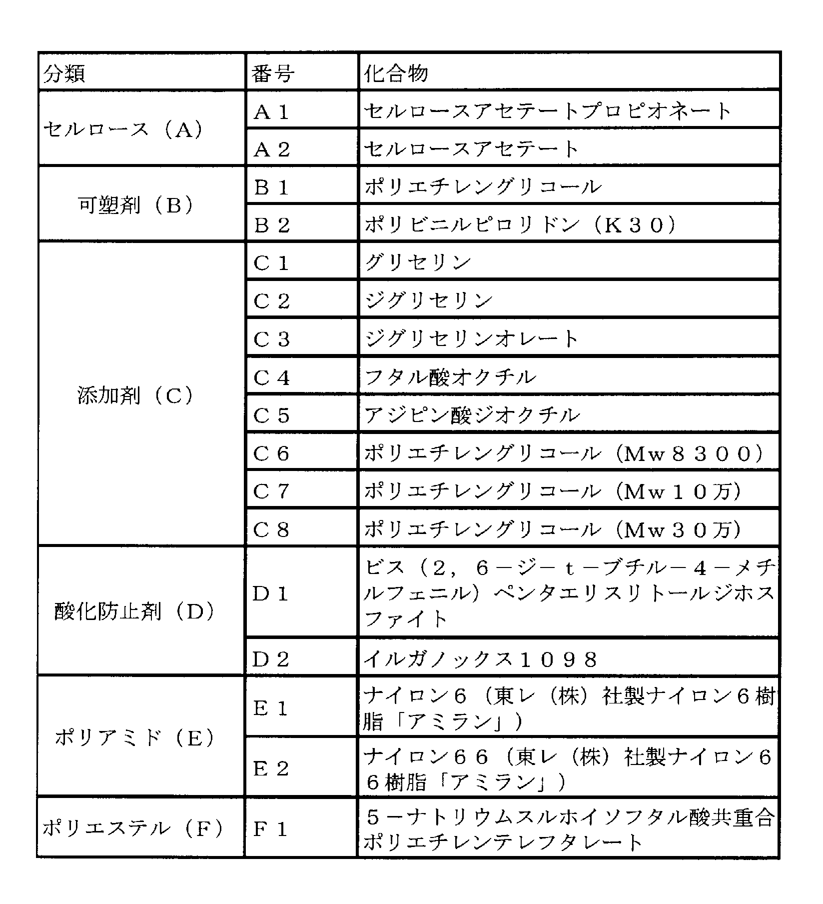
Claims (23)
- セルロースエステル、ポリアミドおよびポリエステルからなる群より選択される少なくとも1種の化合物を主成分とする分離膜であり、
内部に、深さ(D1)が10nm以上500nm以下であり、長さ(L1)が30nm以上であり、かつ、長さと深さの比L1/D1が2以上の範囲にある空隙を複数有し、
1,000~6,500MPaの引張弾性率を示す、分離膜。 A separation membrane mainly comprising at least one compound selected from the group consisting of cellulose ester, polyamide and polyester,
Inside, the depth (D 1 ) is 10 nm or more and 500 nm or less, the length (L 1 ) is 30 nm or more, and the ratio L 1 / D 1 of length to depth is in the range of 2 or more. A plurality of
A separation membrane exhibiting a tensile modulus of 1,000 to 6,500 MPa. - 前記空隙の長手方向が、前記分離膜の長手方向に沿っている、請求項1に記載の分離膜。 The separation membrane according to claim 1, wherein the longitudinal direction of the gap is along the longitudinal direction of the separation membrane.
- 前記分離膜の断面の投影面積をS10とし、前記空隙の占有面積をS1としたとき、(S1/S10)×100で表される、前記断面における空隙の占有率が0.5%以上30%以下である、請求項1または請求項2に記載の分離膜。 When the projected area of the cross section of the separation membrane is S 10 and the occupation area of the void is S 1 , the void occupation ratio in the cross section represented by (S 1 / S 10 ) × 100 is 0.5. The separation membrane according to claim 1 or 2, which is not less than 30% and not more than 30%.
- 少なくとも一方の表面に、長さ(L2)が30nm以上であり、幅(W2)が5nm以上500nm以下であり、かつ、長さと幅の比L2/W2が2以上である複数の溝を有する、請求項1~3のいずれか1項に記載の分離膜。 At least one surface has a length (L 2 ) of 30 nm or more, a width (W 2 ) of 5 nm or more and 500 nm or less, and a length / width ratio L 2 / W 2 of 2 or more. The separation membrane according to any one of claims 1 to 3, which has a groove.
- セルロースエステル、ポリアミドおよびポリエステルからなる群より選択される少なくとも1種の化合物を主成分とする分離膜であり、
少なくとも一方の表面に、長さ(L2)が30nm以上であり、幅(W2)が5nm以上500nm以下であり、かつ、長さと幅の比L2/W2が2以上の範囲にある複数の溝を有し、
1,000~6,500MPaの引張弾性率を示す、分離膜。 A separation membrane mainly comprising at least one compound selected from the group consisting of cellulose ester, polyamide and polyester,
At least one surface has a length (L 2 ) of 30 nm or more, a width (W 2 ) of 5 nm or more and 500 nm or less, and a length / width ratio L 2 / W 2 of 2 or more. Having a plurality of grooves,
A separation membrane exhibiting a tensile modulus of 1,000 to 6,500 MPa. - 前記溝の長手方向が、前記分離膜の長手方向に沿っている、請求項4または5に記載の分離膜。 The separation membrane according to claim 4 or 5, wherein a longitudinal direction of the groove is along a longitudinal direction of the separation membrane.
- 前記分離膜の表面の投影面積をS20とし、前記溝の占有面積をS2としたとき、(S2/S20)×100で表される、前記表面における前記溝の占有率が0.5%以上20%以下である、請求項4~6のいずれか1項に記載の分離膜。 When the projected area of the surface of the separation membrane is S 20 and the occupied area of the groove is S 2 , the occupied ratio of the groove on the surface expressed as (S 2 / S 20 ) × 100 is 0. The separation membrane according to any one of claims 4 to 6, which is 5% or more and 20% or less.
- 第1層および第2層を少なくとも備える分離膜であって、
前記第1層は、セルロースエステル、ポリアミドおよびポリエステルからなる群より選択される少なくとも1種の化合物を主成分とし、
前記第1層の内部に、深さ(D1)が10nm以上500nm以下であり、長さ(L1)が30nm以上であり、かつ、長さと深さの比L1/D1が2以上の範囲にある空隙を複数有し、
引張弾性率が1,000~6,500MPaである分離膜。 A separation membrane comprising at least a first layer and a second layer,
The first layer is mainly composed of at least one compound selected from the group consisting of cellulose ester, polyamide and polyester,
In the first layer, the depth (D 1 ) is 10 nm or more and 500 nm or less, the length (L 1 ) is 30 nm or more, and the length / depth ratio L 1 / D 1 is 2 or more. Having a plurality of voids in the range of
A separation membrane having a tensile modulus of 1,000 to 6,500 MPa. - 前記空隙の長手方向が、前記分離膜の長手方向に沿っている、請求項8に記載の分離膜。 The separation membrane according to claim 8, wherein the longitudinal direction of the gap is along the longitudinal direction of the separation membrane.
- 前記分離膜の断面の投影面積をS10とし、前記空隙の占有面積をS1としたとき、(S1/S10)×100で表される、前記断面における空隙の占有率が0.5%以上30%以下である、請求項8または請求項9に記載の分離膜。 When the projected area of the cross section of the separation membrane is S 10 and the occupation area of the void is S 1 , the void occupation ratio in the cross section represented by (S 1 / S 10 ) × 100 is 0.5. The separation membrane according to claim 8 or 9, which is not less than 30% and not more than 30%.
- 少なくとも一方の表面に、長さ(L2)が30nm以上であり、幅(W2)が5nm以上500nm以下であり、かつ、長さと幅の比L2/W2が2以上である複数の溝を有する、請求項8~10のいずれか1項に記載の分離膜。 At least one surface has a length (L 2 ) of 30 nm or more, a width (W 2 ) of 5 nm or more and 500 nm or less, and a length / width ratio L 2 / W 2 of 2 or more. The separation membrane according to any one of claims 8 to 10, which has a groove.
- 第1層および第2層を少なくとも備える分離膜であって、
前記第1層は、セルロースエステル、ポリアミドおよびポリエステルからなる群より選択される少なくとも1種の化合物を主成分とし、
少なくとも一方の表面に、長さ(L2)が30nm以上であり、幅(W2)が5nm以上500nm以下であり、かつ、長さと幅の比L2/W2が2以上の範囲にある複数の溝を有し、
引張弾性率が1,000~6,500MPaである分離膜。 A separation membrane comprising at least a first layer and a second layer,
The first layer is mainly composed of at least one compound selected from the group consisting of cellulose ester, polyamide and polyester,
At least one surface has a length (L 2 ) of 30 nm or more, a width (W 2 ) of 5 nm or more and 500 nm or less, and a length / width ratio L 2 / W 2 of 2 or more. Having a plurality of grooves,
A separation membrane having a tensile modulus of 1,000 to 6,500 MPa. - 前記溝の長手方向が、前記分離膜の長手方向に沿っている、請求項11または12に記載の分離膜。 The separation membrane according to claim 11 or 12, wherein a longitudinal direction of the groove is along a longitudinal direction of the separation membrane.
- 前記分離膜の表面の投影面積をS20とし、前記溝の占有面積をS2としたとき、(S2/S20)×100で表される、前記表面における前記溝の占有率が0.5%以上20%以下である、請求項11~13のいずれか1項に記載の分離膜。 When the projected area of the surface of the separation membrane is S 20 and the occupied area of the groove is S 2 , the occupied ratio of the groove on the surface expressed as (S 2 / S 20 ) × 100 is 0. The separation membrane according to any one of claims 11 to 13, which is 5% or more and 20% or less.
- 前記第1層の断面における空隙の占有率VA、前記第2層の開孔率HBが、VA<HBを満たす、請求項8~14のいずれか1項に記載の分離膜。 The separation membrane according to any one of claims 8 to 14, wherein a void occupation ratio V A in the cross section of the first layer and a hole area ratio H B of the second layer satisfy V A <H B.
- 前記第1層の厚みが0.01~90μmである、請求項8~15のいずれか1項に記載の分離膜。 The separation membrane according to any one of claims 8 to 15, wherein the thickness of the first layer is 0.01 to 90 µm.
- 前記分離膜が中空糸形状である、請求項1~16のいずれか1項に記載の分離膜。 The separation membrane according to any one of claims 1 to 16, wherein the separation membrane has a hollow fiber shape.
- 前記中空糸の外径が20~400μmである、請求項17に記載の分離膜。 The separation membrane according to claim 17, wherein the hollow fiber has an outer diameter of 20 to 400 µm.
- 前記分離膜は、前記セルロースエステルを主成分として含有し、
前記分離膜は、セルロースアセテートプロピオネート及びセルロースアセテートブチレートの少なくとも一方を前記セルロースエステルとして含有する、請求項1~18のいずれか1項に記載の分離膜。 The separation membrane contains the cellulose ester as a main component,
The separation membrane according to any one of claims 1 to 18, wherein the separation membrane contains at least one of cellulose acetate propionate and cellulose acetate butyrate as the cellulose ester. - 前記分離膜は前記ポリアミドを主成分として含有し、
前記分離膜は、ナイロン6およびナイロン66の少なくとも一方を前記ポリアミドとして含有する、請求項1~19のいずれか1項に記載の分離膜。 The separation membrane contains the polyamide as a main component,
The separation membrane according to any one of claims 1 to 19, wherein the separation membrane contains at least one of nylon 6 and nylon 66 as the polyamide. - 前記分離膜がポリエステルを主成分として含有し、
前記分離膜は、5-ナトリウムスルホイソフタル酸共重合ポリエチレンテレフタレートをポリエステルとして含有する、請求項1~20のいずれか1項に記載の分離膜。 The separation membrane contains polyester as a main component,
The separation membrane according to any one of claims 1 to 20, wherein the separation membrane contains 5-sodium sulfoisophthalic acid copolymerized polyethylene terephthalate as a polyester. - 前記分離膜が、ナノ濾過膜、逆浸透膜、正浸透膜およびガス分離膜からなる群より選ばれる少なくとも一つである、請求項1~21のいずれか1項に記載の分離膜。 The separation membrane according to any one of claims 1 to 21, wherein the separation membrane is at least one selected from the group consisting of a nanofiltration membrane, a reverse osmosis membrane, a forward osmosis membrane, and a gas separation membrane.
- 請求項1~22のいずれか1項に記載の分離膜を備える膜モジュール。 A membrane module comprising the separation membrane according to any one of claims 1 to 22.
Priority Applications (6)
| Application Number | Priority Date | Filing Date | Title |
|---|---|---|---|
| JP2016522822A JP6132071B2 (en) | 2015-03-31 | 2016-03-31 | Separation membrane |
| CN201680019186.2A CN107530644B (en) | 2015-03-31 | 2016-03-31 | Seperation film |
| US15/563,315 US10639595B2 (en) | 2015-03-31 | 2016-03-31 | Separation membrane |
| EP16773213.0A EP3278867B1 (en) | 2015-03-31 | 2016-03-31 | Separation membrane |
| KR1020177027564A KR102337389B1 (en) | 2015-03-31 | 2016-03-31 | separator |
| US16/810,423 US11103836B2 (en) | 2015-03-31 | 2020-03-05 | Separation membrane |
Applications Claiming Priority (2)
| Application Number | Priority Date | Filing Date | Title |
|---|---|---|---|
| JP2015-072327 | 2015-03-31 | ||
| JP2015072327 | 2015-03-31 |
Related Child Applications (2)
| Application Number | Title | Priority Date | Filing Date |
|---|---|---|---|
| US15/563,315 A-371-Of-International US10639595B2 (en) | 2015-03-31 | 2016-03-31 | Separation membrane |
| US16/810,423 Division US11103836B2 (en) | 2015-03-31 | 2020-03-05 | Separation membrane |
Publications (1)
| Publication Number | Publication Date |
|---|---|
| WO2016159333A1 true WO2016159333A1 (en) | 2016-10-06 |
Family
ID=57006885
Family Applications (1)
| Application Number | Title | Priority Date | Filing Date |
|---|---|---|---|
| PCT/JP2016/060861 WO2016159333A1 (en) | 2015-03-31 | 2016-03-31 | Separation membrane |
Country Status (7)
| Country | Link |
|---|---|
| US (2) | US10639595B2 (en) |
| EP (1) | EP3278867B1 (en) |
| JP (1) | JP6132071B2 (en) |
| KR (1) | KR102337389B1 (en) |
| CN (1) | CN107530644B (en) |
| HU (1) | HUE056079T2 (en) |
| WO (1) | WO2016159333A1 (en) |
Cited By (7)
| Publication number | Priority date | Publication date | Assignee | Title |
|---|---|---|---|---|
| WO2018079807A1 (en) * | 2016-10-31 | 2018-05-03 | 東洋紡株式会社 | Cellulose acetate-type asymmetric hollow fiber membrane |
| WO2018079808A1 (en) * | 2016-10-31 | 2018-05-03 | 東洋紡株式会社 | Cellulose acetate based hollow fiber membrane |
| KR20190118165A (en) * | 2017-02-28 | 2019-10-17 | 도레이 카부시키가이샤 | Composite hollow fiber membrane and its manufacturing method |
| CN110475606A (en) * | 2017-03-30 | 2019-11-19 | 东丽株式会社 | Seperation film and its manufacturing method |
| CN110475605A (en) * | 2017-03-30 | 2019-11-19 | 东丽株式会社 | The manufacturing method of seperation film and seperation film |
| WO2021132397A1 (en) * | 2019-12-23 | 2021-07-01 | 東レ株式会社 | Separation membrane and method for producing same |
| KR20220113961A (en) | 2019-12-23 | 2022-08-17 | 도레이 카부시키가이샤 | Separator and manufacturing method of the separation membrane |
Families Citing this family (6)
| Publication number | Priority date | Publication date | Assignee | Title |
|---|---|---|---|---|
| EP3202486A4 (en) * | 2014-09-30 | 2018-05-23 | Toray Industries, Inc. | Separation membrane |
| US10478782B2 (en) | 2015-04-28 | 2019-11-19 | Toray Industries, Inc. | Composite hollow fiber membrane and method for producing same |
| EP3409346A4 (en) * | 2016-01-29 | 2019-09-25 | Toray Industries, Inc. | Separation membrane |
| US11202986B2 (en) | 2017-10-09 | 2021-12-21 | Ali Pournaghshband Isfahani | Plasticization-resistant polyurethane membrane and preparation method thereof |
| KR102212128B1 (en) | 2018-05-10 | 2021-02-17 | 주식회사 엘지화학 | Reverse osmosis membrane, method for preparing reverse osmosis membrane, and water treatment module |
| US11283085B1 (en) * | 2020-03-06 | 2022-03-22 | Bloom Energy Corporation | Low VOC ink compositions and methods of forming fuel cell system components using the same |
Citations (7)
| Publication number | Priority date | Publication date | Assignee | Title |
|---|---|---|---|---|
| JPH11114381A (en) * | 1997-10-16 | 1999-04-27 | Nitto Denko Corp | Spiral type membrane element |
| JP2005076012A (en) * | 2003-09-03 | 2005-03-24 | Toagosei Co Ltd | Continuously manufacturing method for functional membrane |
| JP2008515668A (en) * | 2004-10-06 | 2008-05-15 | ザ リサーチ ファウンデーション オブ ステイト ユニバーシティー オブ ニューヨーク | High flow rate and low adhesion filtration media |
| JP2009226397A (en) * | 2008-02-27 | 2009-10-08 | Toray Ind Inc | Hollow fiber membrane for humidification and membrane module for humidification |
| WO2012035692A1 (en) * | 2010-09-16 | 2012-03-22 | 株式会社日立製作所 | Water separation membrane module |
| WO2013047746A1 (en) * | 2011-09-29 | 2013-04-04 | 東レ株式会社 | Separation membrane, separation membrane element, and production method for separation membrane |
| JP2015047530A (en) * | 2013-08-30 | 2015-03-16 | 日揮触媒化成株式会社 | Substrate having water-repellent transparent coating for water treatment and manufacturing method of the same |
Family Cites Families (14)
| Publication number | Priority date | Publication date | Assignee | Title |
|---|---|---|---|---|
| JPS5170316A (en) | 1974-12-16 | 1976-06-17 | Teijin Ltd | SERUROOSUASETEETOCHUKUSHINO SEIZOHOHO |
| AU529368B2 (en) * | 1978-05-15 | 1983-06-02 | Pall Corporation | Preparing polyamide membrane filter media and product |
| CA1141114A (en) * | 1978-11-24 | 1983-02-15 | Masamichi Ishida | Regenerated cellulose hollow fiber and process for manufacturing same |
| CA1272139C (en) * | 1984-11-16 | 1990-07-31 | Fluid separator, hollow fiber to be used for construction thereof and process for preparation of said hollow fibers | |
| US4867934A (en) * | 1987-12-23 | 1989-09-19 | Cuno, Inc. | Production of hollow nylon fibers |
| JP3601902B2 (en) | 1996-04-12 | 2004-12-15 | ユニチカ株式会社 | Microporous hollow polyamide fiber having openings and method for producing the same |
| KR100805977B1 (en) * | 2001-08-01 | 2008-02-25 | 아사히 가세이 메디컬 가부시키가이샤 | Multilayer Microporous Film |
| JP4957141B2 (en) | 2005-09-30 | 2012-06-20 | 東レ株式会社 | Cellulose fatty acid mixed ester hollow fiber |
| US8800783B2 (en) * | 2008-09-30 | 2014-08-12 | Unitika Ltd. | Polyamide hollow fiber membrane, and production method thereof |
| EP2609994A4 (en) | 2010-08-27 | 2015-08-26 | Toyo Boseki | Hollow fiber type reverse osmosis membrane and process for production thereof |
| KR20140082677A (en) | 2011-09-29 | 2014-07-02 | 도레이 카부시키가이샤 | Separation membrane and separation membrane element |
| KR102073447B1 (en) * | 2012-08-20 | 2020-02-04 | 유니티카 가부시끼가이샤 | Porous polyamide hollow fiber membrane having very small pore diameter,and method for producing same |
| EP3202486A4 (en) | 2014-09-30 | 2018-05-23 | Toray Industries, Inc. | Separation membrane |
| US10478782B2 (en) | 2015-04-28 | 2019-11-19 | Toray Industries, Inc. | Composite hollow fiber membrane and method for producing same |
-
2016
- 2016-03-31 JP JP2016522822A patent/JP6132071B2/en active Active
- 2016-03-31 US US15/563,315 patent/US10639595B2/en active Active
- 2016-03-31 CN CN201680019186.2A patent/CN107530644B/en active Active
- 2016-03-31 HU HUE16773213A patent/HUE056079T2/en unknown
- 2016-03-31 KR KR1020177027564A patent/KR102337389B1/en active IP Right Grant
- 2016-03-31 EP EP16773213.0A patent/EP3278867B1/en active Active
- 2016-03-31 WO PCT/JP2016/060861 patent/WO2016159333A1/en active Application Filing
-
2020
- 2020-03-05 US US16/810,423 patent/US11103836B2/en active Active
Patent Citations (7)
| Publication number | Priority date | Publication date | Assignee | Title |
|---|---|---|---|---|
| JPH11114381A (en) * | 1997-10-16 | 1999-04-27 | Nitto Denko Corp | Spiral type membrane element |
| JP2005076012A (en) * | 2003-09-03 | 2005-03-24 | Toagosei Co Ltd | Continuously manufacturing method for functional membrane |
| JP2008515668A (en) * | 2004-10-06 | 2008-05-15 | ザ リサーチ ファウンデーション オブ ステイト ユニバーシティー オブ ニューヨーク | High flow rate and low adhesion filtration media |
| JP2009226397A (en) * | 2008-02-27 | 2009-10-08 | Toray Ind Inc | Hollow fiber membrane for humidification and membrane module for humidification |
| WO2012035692A1 (en) * | 2010-09-16 | 2012-03-22 | 株式会社日立製作所 | Water separation membrane module |
| WO2013047746A1 (en) * | 2011-09-29 | 2013-04-04 | 東レ株式会社 | Separation membrane, separation membrane element, and production method for separation membrane |
| JP2015047530A (en) * | 2013-08-30 | 2015-03-16 | 日揮触媒化成株式会社 | Substrate having water-repellent transparent coating for water treatment and manufacturing method of the same |
Non-Patent Citations (1)
| Title |
|---|
| See also references of EP3278867A4 * |
Cited By (33)
| Publication number | Priority date | Publication date | Assignee | Title |
|---|---|---|---|---|
| CN109890490B (en) * | 2016-10-31 | 2021-10-12 | 东洋纺株式会社 | Cellulose acetate series asymmetric hollow fiber membrane |
| US11014053B2 (en) | 2016-10-31 | 2021-05-25 | Toyobo Co., Ltd. | Cellulose acetate-based asymmetric hollow fiber membrane |
| CN109890490A (en) * | 2016-10-31 | 2019-06-14 | 东洋纺株式会社 | Acetate fiber prime system asymmetric hollow fiber membrane |
| CN109922876A (en) * | 2016-10-31 | 2019-06-21 | 东洋纺株式会社 | Acetate fiber prime system hollow-fibre membrane |
| JPWO2018079807A1 (en) * | 2016-10-31 | 2019-08-08 | 東洋紡株式会社 | Cellulose acetate asymmetric hollow fiber membrane |
| JPWO2018079808A1 (en) * | 2016-10-31 | 2019-09-19 | 東洋紡株式会社 | Cellulose acetate hollow fiber membrane |
| WO2018079808A1 (en) * | 2016-10-31 | 2018-05-03 | 東洋紡株式会社 | Cellulose acetate based hollow fiber membrane |
| EP3533515A4 (en) * | 2016-10-31 | 2020-06-24 | Toyobo Co., Ltd. | Cellulose acetate based hollow fiber membrane |
| EP3533514A4 (en) * | 2016-10-31 | 2020-06-24 | Toyobo Co., Ltd. | Cellulose acetate-type asymmetric hollow fiber membrane |
| WO2018079807A1 (en) * | 2016-10-31 | 2018-05-03 | 東洋紡株式会社 | Cellulose acetate-type asymmetric hollow fiber membrane |
| US11007490B2 (en) | 2016-10-31 | 2021-05-18 | Toyobo Co., Ltd. | Cellulose acetate-based hollow fiber membrane |
| US11369925B2 (en) | 2017-02-28 | 2022-06-28 | Toray Industries, Inc. | Composite hollow-fiber membrane and production method therefor |
| EP3574987A4 (en) * | 2017-02-28 | 2020-12-09 | Toray Industries, Inc. | Composite hollow-fiber membrane and production method therefor |
| KR20190118165A (en) * | 2017-02-28 | 2019-10-17 | 도레이 카부시키가이샤 | Composite hollow fiber membrane and its manufacturing method |
| KR102407778B1 (en) * | 2017-02-28 | 2022-06-10 | 도레이 카부시키가이샤 | Composite hollow fiber membrane and its manufacturing method |
| EP3603780A4 (en) * | 2017-03-30 | 2020-12-16 | Toray Industries, Inc. | Separation film and production method therefor |
| JP7120006B2 (en) | 2017-03-30 | 2022-08-17 | 東レ株式会社 | separation membrane |
| JPWO2018182028A1 (en) * | 2017-03-30 | 2020-02-06 | 東レ株式会社 | Separation membrane and method for producing the same |
| KR20190131503A (en) * | 2017-03-30 | 2019-11-26 | 도레이 카부시키가이샤 | Separator and its manufacturing method |
| US11446611B2 (en) | 2017-03-30 | 2022-09-20 | Toray Industries, Inc. | Separating membrane and method for manufacturing separating membrane |
| EP3603779A4 (en) * | 2017-03-30 | 2020-06-17 | Toray Industries, Inc. | Separating membrane and method for manufacturing separating membrane |
| US11103835B2 (en) | 2017-03-30 | 2021-08-31 | Toray Industries, Inc. | Separation film and production method therefor |
| KR20190129890A (en) * | 2017-03-30 | 2019-11-20 | 도레이 카부시키가이샤 | Separator and Manufacturing Method |
| KR102321324B1 (en) * | 2017-03-30 | 2021-11-02 | 도레이 카부시키가이샤 | Separator and its manufacturing method |
| KR102326440B1 (en) * | 2017-03-30 | 2021-11-12 | 도레이 카부시키가이샤 | Separator and method for manufacturing the separation membrane |
| CN110475605B (en) * | 2017-03-30 | 2022-04-12 | 东丽株式会社 | Separation membrane and method for producing separation membrane |
| CN110475605A (en) * | 2017-03-30 | 2019-11-19 | 东丽株式会社 | The manufacturing method of seperation film and seperation film |
| CN110475606A (en) * | 2017-03-30 | 2019-11-19 | 东丽株式会社 | Seperation film and its manufacturing method |
| JPWO2021132397A1 (en) * | 2019-12-23 | 2021-07-01 | ||
| JP7107429B2 (en) | 2019-12-23 | 2022-07-27 | 東レ株式会社 | Separation membrane and its manufacturing method |
| KR20220113961A (en) | 2019-12-23 | 2022-08-17 | 도레이 카부시키가이샤 | Separator and manufacturing method of the separation membrane |
| WO2021132397A1 (en) * | 2019-12-23 | 2021-07-01 | 東レ株式会社 | Separation membrane and method for producing same |
| US11794150B2 (en) | 2019-12-23 | 2023-10-24 | Toray Industries, Inc. | Separation membrane and method for producing separation membrane |
Also Published As
| Publication number | Publication date |
|---|---|
| EP3278867B1 (en) | 2021-09-08 |
| HUE056079T2 (en) | 2022-01-28 |
| US10639595B2 (en) | 2020-05-05 |
| KR102337389B1 (en) | 2021-12-10 |
| EP3278867A1 (en) | 2018-02-07 |
| US11103836B2 (en) | 2021-08-31 |
| KR20170131474A (en) | 2017-11-29 |
| JP6132071B2 (en) | 2017-05-24 |
| CN107530644A (en) | 2018-01-02 |
| EP3278867A4 (en) | 2018-08-29 |
| CN107530644B (en) | 2018-11-20 |
| US20200197880A1 (en) | 2020-06-25 |
| JPWO2016159333A1 (en) | 2017-04-27 |
| US20180065093A1 (en) | 2018-03-08 |
Similar Documents
| Publication | Publication Date | Title |
|---|---|---|
| JP6132071B2 (en) | Separation membrane | |
| JP6729563B2 (en) | Composite hollow fiber membrane and method for producing the same | |
| JP6699172B2 (en) | Separation membrane | |
| JP6763374B2 (en) | Separation membrane | |
| US11446611B2 (en) | Separating membrane and method for manufacturing separating membrane | |
| JP2017136587A (en) | Separation membrane | |
| JP2017177040A (en) | Cellulose ester hollow fiber membrane and method for producing the same | |
| WO2018021545A1 (en) | Separation membrane and production process therefor | |
| KR102407778B1 (en) | Composite hollow fiber membrane and its manufacturing method |
Legal Events
| Date | Code | Title | Description |
|---|---|---|---|
| ENP | Entry into the national phase |
Ref document number: 2016522822 Country of ref document: JP Kind code of ref document: A |
|
| 121 | Ep: the epo has been informed by wipo that ep was designated in this application |
Ref document number: 16773213 Country of ref document: EP Kind code of ref document: A1 |
|
| ENP | Entry into the national phase |
Ref document number: 20177027564 Country of ref document: KR Kind code of ref document: A |
|
| WWE | Wipo information: entry into national phase |
Ref document number: 15563315 Country of ref document: US |
|
| REEP | Request for entry into the european phase |
Ref document number: 2016773213 Country of ref document: EP |
|
| NENP | Non-entry into the national phase |
Ref country code: DE |