WO2016159201A1 - 露光装置、フラットパネルディスプレイの製造方法、デバイス製造方法、及び露光方法 - Google Patents
露光装置、フラットパネルディスプレイの製造方法、デバイス製造方法、及び露光方法 Download PDFInfo
- Publication number
- WO2016159201A1 WO2016159201A1 PCT/JP2016/060593 JP2016060593W WO2016159201A1 WO 2016159201 A1 WO2016159201 A1 WO 2016159201A1 JP 2016060593 W JP2016060593 W JP 2016060593W WO 2016159201 A1 WO2016159201 A1 WO 2016159201A1
- Authority
- WO
- WIPO (PCT)
- Prior art keywords
- projection optical
- optical system
- detection unit
- exposure
- mark detection
- Prior art date
- Legal status (The legal status is an assumption and is not a legal conclusion. Google has not performed a legal analysis and makes no representation as to the accuracy of the status listed.)
- Ceased
Links
Images




Classifications
-
- G—PHYSICS
- G03—PHOTOGRAPHY; CINEMATOGRAPHY; ANALOGOUS TECHNIQUES USING WAVES OTHER THAN OPTICAL WAVES; ELECTROGRAPHY; HOLOGRAPHY
- G03F—PHOTOMECHANICAL PRODUCTION OF TEXTURED OR PATTERNED SURFACES, e.g. FOR PRINTING, FOR PROCESSING OF SEMICONDUCTOR DEVICES; MATERIALS THEREFOR; ORIGINALS THEREFOR; APPARATUS SPECIALLY ADAPTED THEREFOR
- G03F7/00—Photomechanical, e.g. photolithographic, production of textured or patterned surfaces, e.g. printing surfaces; Materials therefor, e.g. comprising photoresists; Apparatus specially adapted therefor
- G03F7/70—Microphotolithographic exposure; Apparatus therefor
- G03F7/70216—Mask projection systems
- G03F7/70258—Projection system adjustments, e.g. adjustments during exposure or alignment during assembly of projection system
-
- G—PHYSICS
- G02—OPTICS
- G02F—OPTICAL DEVICES OR ARRANGEMENTS FOR THE CONTROL OF LIGHT BY MODIFICATION OF THE OPTICAL PROPERTIES OF THE MEDIA OF THE ELEMENTS INVOLVED THEREIN; NON-LINEAR OPTICS; FREQUENCY-CHANGING OF LIGHT; OPTICAL LOGIC ELEMENTS; OPTICAL ANALOGUE/DIGITAL CONVERTERS
- G02F1/00—Devices or arrangements for the control of the intensity, colour, phase, polarisation or direction of light arriving from an independent light source, e.g. switching, gating or modulating; Non-linear optics
- G02F1/01—Devices or arrangements for the control of the intensity, colour, phase, polarisation or direction of light arriving from an independent light source, e.g. switching, gating or modulating; Non-linear optics for the control of the intensity, phase, polarisation or colour
- G02F1/13—Devices or arrangements for the control of the intensity, colour, phase, polarisation or direction of light arriving from an independent light source, e.g. switching, gating or modulating; Non-linear optics for the control of the intensity, phase, polarisation or colour based on liquid crystals, e.g. single liquid crystal display cells
-
- G—PHYSICS
- G03—PHOTOGRAPHY; CINEMATOGRAPHY; ANALOGOUS TECHNIQUES USING WAVES OTHER THAN OPTICAL WAVES; ELECTROGRAPHY; HOLOGRAPHY
- G03F—PHOTOMECHANICAL PRODUCTION OF TEXTURED OR PATTERNED SURFACES, e.g. FOR PRINTING, FOR PROCESSING OF SEMICONDUCTOR DEVICES; MATERIALS THEREFOR; ORIGINALS THEREFOR; APPARATUS SPECIALLY ADAPTED THEREFOR
- G03F7/00—Photomechanical, e.g. photolithographic, production of textured or patterned surfaces, e.g. printing surfaces; Materials therefor, e.g. comprising photoresists; Apparatus specially adapted therefor
- G03F7/20—Exposure; Apparatus therefor
-
- G—PHYSICS
- G03—PHOTOGRAPHY; CINEMATOGRAPHY; ANALOGOUS TECHNIQUES USING WAVES OTHER THAN OPTICAL WAVES; ELECTROGRAPHY; HOLOGRAPHY
- G03F—PHOTOMECHANICAL PRODUCTION OF TEXTURED OR PATTERNED SURFACES, e.g. FOR PRINTING, FOR PROCESSING OF SEMICONDUCTOR DEVICES; MATERIALS THEREFOR; ORIGINALS THEREFOR; APPARATUS SPECIALLY ADAPTED THEREFOR
- G03F7/00—Photomechanical, e.g. photolithographic, production of textured or patterned surfaces, e.g. printing surfaces; Materials therefor, e.g. comprising photoresists; Apparatus specially adapted therefor
- G03F7/70—Microphotolithographic exposure; Apparatus therefor
- G03F7/70058—Mask illumination systems
- G03F7/70141—Illumination system adjustment, e.g. adjustments during exposure or alignment during assembly of illumination system
-
- G—PHYSICS
- G03—PHOTOGRAPHY; CINEMATOGRAPHY; ANALOGOUS TECHNIQUES USING WAVES OTHER THAN OPTICAL WAVES; ELECTROGRAPHY; HOLOGRAPHY
- G03F—PHOTOMECHANICAL PRODUCTION OF TEXTURED OR PATTERNED SURFACES, e.g. FOR PRINTING, FOR PROCESSING OF SEMICONDUCTOR DEVICES; MATERIALS THEREFOR; ORIGINALS THEREFOR; APPARATUS SPECIALLY ADAPTED THEREFOR
- G03F7/00—Photomechanical, e.g. photolithographic, production of textured or patterned surfaces, e.g. printing surfaces; Materials therefor, e.g. comprising photoresists; Apparatus specially adapted therefor
- G03F7/70—Microphotolithographic exposure; Apparatus therefor
- G03F7/70216—Mask projection systems
- G03F7/70275—Multiple projection paths, e.g. array of projection systems, microlens projection systems or tandem projection systems
-
- G—PHYSICS
- G03—PHOTOGRAPHY; CINEMATOGRAPHY; ANALOGOUS TECHNIQUES USING WAVES OTHER THAN OPTICAL WAVES; ELECTROGRAPHY; HOLOGRAPHY
- G03F—PHOTOMECHANICAL PRODUCTION OF TEXTURED OR PATTERNED SURFACES, e.g. FOR PRINTING, FOR PROCESSING OF SEMICONDUCTOR DEVICES; MATERIALS THEREFOR; ORIGINALS THEREFOR; APPARATUS SPECIALLY ADAPTED THEREFOR
- G03F7/00—Photomechanical, e.g. photolithographic, production of textured or patterned surfaces, e.g. printing surfaces; Materials therefor, e.g. comprising photoresists; Apparatus specially adapted therefor
- G03F7/70—Microphotolithographic exposure; Apparatus therefor
- G03F7/70216—Mask projection systems
- G03F7/70358—Scanning exposure, i.e. relative movement of patterned beam and workpiece during imaging
-
- G—PHYSICS
- G03—PHOTOGRAPHY; CINEMATOGRAPHY; ANALOGOUS TECHNIQUES USING WAVES OTHER THAN OPTICAL WAVES; ELECTROGRAPHY; HOLOGRAPHY
- G03F—PHOTOMECHANICAL PRODUCTION OF TEXTURED OR PATTERNED SURFACES, e.g. FOR PRINTING, FOR PROCESSING OF SEMICONDUCTOR DEVICES; MATERIALS THEREFOR; ORIGINALS THEREFOR; APPARATUS SPECIALLY ADAPTED THEREFOR
- G03F7/00—Photomechanical, e.g. photolithographic, production of textured or patterned surfaces, e.g. printing surfaces; Materials therefor, e.g. comprising photoresists; Apparatus specially adapted therefor
- G03F7/70—Microphotolithographic exposure; Apparatus therefor
- G03F7/70483—Information management; Active and passive control; Testing; Wafer monitoring, e.g. pattern monitoring
- G03F7/70491—Information management, e.g. software; Active and passive control, e.g. details of controlling exposure processes or exposure tool monitoring processes
- G03F7/70516—Calibration of components of the microlithographic apparatus, e.g. light sources, addressable masks or detectors
-
- G—PHYSICS
- G03—PHOTOGRAPHY; CINEMATOGRAPHY; ANALOGOUS TECHNIQUES USING WAVES OTHER THAN OPTICAL WAVES; ELECTROGRAPHY; HOLOGRAPHY
- G03F—PHOTOMECHANICAL PRODUCTION OF TEXTURED OR PATTERNED SURFACES, e.g. FOR PRINTING, FOR PROCESSING OF SEMICONDUCTOR DEVICES; MATERIALS THEREFOR; ORIGINALS THEREFOR; APPARATUS SPECIALLY ADAPTED THEREFOR
- G03F7/00—Photomechanical, e.g. photolithographic, production of textured or patterned surfaces, e.g. printing surfaces; Materials therefor, e.g. comprising photoresists; Apparatus specially adapted therefor
- G03F7/70—Microphotolithographic exposure; Apparatus therefor
- G03F7/70483—Information management; Active and passive control; Testing; Wafer monitoring, e.g. pattern monitoring
- G03F7/70605—Workpiece metrology
- G03F7/70681—Metrology strategies
- G03F7/70683—Mark designs
-
- G—PHYSICS
- G03—PHOTOGRAPHY; CINEMATOGRAPHY; ANALOGOUS TECHNIQUES USING WAVES OTHER THAN OPTICAL WAVES; ELECTROGRAPHY; HOLOGRAPHY
- G03F—PHOTOMECHANICAL PRODUCTION OF TEXTURED OR PATTERNED SURFACES, e.g. FOR PRINTING, FOR PROCESSING OF SEMICONDUCTOR DEVICES; MATERIALS THEREFOR; ORIGINALS THEREFOR; APPARATUS SPECIALLY ADAPTED THEREFOR
- G03F7/00—Photomechanical, e.g. photolithographic, production of textured or patterned surfaces, e.g. printing surfaces; Materials therefor, e.g. comprising photoresists; Apparatus specially adapted therefor
- G03F7/70—Microphotolithographic exposure; Apparatus therefor
- G03F7/70483—Information management; Active and passive control; Testing; Wafer monitoring, e.g. pattern monitoring
- G03F7/70605—Workpiece metrology
- G03F7/706843—Metrology apparatus
- G03F7/706845—Calibration, e.g. tool-to-tool calibration, beam alignment, spot position or focus
-
- G—PHYSICS
- G03—PHOTOGRAPHY; CINEMATOGRAPHY; ANALOGOUS TECHNIQUES USING WAVES OTHER THAN OPTICAL WAVES; ELECTROGRAPHY; HOLOGRAPHY
- G03F—PHOTOMECHANICAL PRODUCTION OF TEXTURED OR PATTERNED SURFACES, e.g. FOR PRINTING, FOR PROCESSING OF SEMICONDUCTOR DEVICES; MATERIALS THEREFOR; ORIGINALS THEREFOR; APPARATUS SPECIALLY ADAPTED THEREFOR
- G03F7/00—Photomechanical, e.g. photolithographic, production of textured or patterned surfaces, e.g. printing surfaces; Materials therefor, e.g. comprising photoresists; Apparatus specially adapted therefor
- G03F7/70—Microphotolithographic exposure; Apparatus therefor
- G03F7/70691—Handling of masks or workpieces
- G03F7/70775—Position control, e.g. interferometers or encoders for determining the stage position
-
- G—PHYSICS
- G03—PHOTOGRAPHY; CINEMATOGRAPHY; ANALOGOUS TECHNIQUES USING WAVES OTHER THAN OPTICAL WAVES; ELECTROGRAPHY; HOLOGRAPHY
- G03F—PHOTOMECHANICAL PRODUCTION OF TEXTURED OR PATTERNED SURFACES, e.g. FOR PRINTING, FOR PROCESSING OF SEMICONDUCTOR DEVICES; MATERIALS THEREFOR; ORIGINALS THEREFOR; APPARATUS SPECIALLY ADAPTED THEREFOR
- G03F7/00—Photomechanical, e.g. photolithographic, production of textured or patterned surfaces, e.g. printing surfaces; Materials therefor, e.g. comprising photoresists; Apparatus specially adapted therefor
- G03F7/70—Microphotolithographic exposure; Apparatus therefor
- G03F7/70691—Handling of masks or workpieces
- G03F7/70791—Large workpieces, e.g. glass substrates for flat panel displays or solar panels
-
- G—PHYSICS
- G03—PHOTOGRAPHY; CINEMATOGRAPHY; ANALOGOUS TECHNIQUES USING WAVES OTHER THAN OPTICAL WAVES; ELECTROGRAPHY; HOLOGRAPHY
- G03F—PHOTOMECHANICAL PRODUCTION OF TEXTURED OR PATTERNED SURFACES, e.g. FOR PRINTING, FOR PROCESSING OF SEMICONDUCTOR DEVICES; MATERIALS THEREFOR; ORIGINALS THEREFOR; APPARATUS SPECIALLY ADAPTED THEREFOR
- G03F7/00—Photomechanical, e.g. photolithographic, production of textured or patterned surfaces, e.g. printing surfaces; Materials therefor, e.g. comprising photoresists; Apparatus specially adapted therefor
- G03F7/70—Microphotolithographic exposure; Apparatus therefor
- G03F7/708—Construction of apparatus, e.g. environment aspects, hygiene aspects or materials
- G03F7/7085—Detection arrangement, e.g. detectors of apparatus alignment possibly mounted on wafers, exposure dose, photo-cleaning flux, stray light, thermal load
-
- G—PHYSICS
- G03—PHOTOGRAPHY; CINEMATOGRAPHY; ANALOGOUS TECHNIQUES USING WAVES OTHER THAN OPTICAL WAVES; ELECTROGRAPHY; HOLOGRAPHY
- G03F—PHOTOMECHANICAL PRODUCTION OF TEXTURED OR PATTERNED SURFACES, e.g. FOR PRINTING, FOR PROCESSING OF SEMICONDUCTOR DEVICES; MATERIALS THEREFOR; ORIGINALS THEREFOR; APPARATUS SPECIALLY ADAPTED THEREFOR
- G03F9/00—Registration or positioning of originals, masks, frames, photographic sheets or textured or patterned surfaces, e.g. automatically
-
- G—PHYSICS
- G03—PHOTOGRAPHY; CINEMATOGRAPHY; ANALOGOUS TECHNIQUES USING WAVES OTHER THAN OPTICAL WAVES; ELECTROGRAPHY; HOLOGRAPHY
- G03F—PHOTOMECHANICAL PRODUCTION OF TEXTURED OR PATTERNED SURFACES, e.g. FOR PRINTING, FOR PROCESSING OF SEMICONDUCTOR DEVICES; MATERIALS THEREFOR; ORIGINALS THEREFOR; APPARATUS SPECIALLY ADAPTED THEREFOR
- G03F9/00—Registration or positioning of originals, masks, frames, photographic sheets or textured or patterned surfaces, e.g. automatically
- G03F9/70—Registration or positioning of originals, masks, frames, photographic sheets or textured or patterned surfaces, e.g. automatically for microlithography
- G03F9/7003—Alignment type or strategy, e.g. leveling, global alignment
- G03F9/7046—Strategy, e.g. mark, sensor or wavelength selection
-
- G—PHYSICS
- G03—PHOTOGRAPHY; CINEMATOGRAPHY; ANALOGOUS TECHNIQUES USING WAVES OTHER THAN OPTICAL WAVES; ELECTROGRAPHY; HOLOGRAPHY
- G03F—PHOTOMECHANICAL PRODUCTION OF TEXTURED OR PATTERNED SURFACES, e.g. FOR PRINTING, FOR PROCESSING OF SEMICONDUCTOR DEVICES; MATERIALS THEREFOR; ORIGINALS THEREFOR; APPARATUS SPECIALLY ADAPTED THEREFOR
- G03F9/00—Registration or positioning of originals, masks, frames, photographic sheets or textured or patterned surfaces, e.g. automatically
- G03F9/70—Registration or positioning of originals, masks, frames, photographic sheets or textured or patterned surfaces, e.g. automatically for microlithography
- G03F9/7088—Alignment mark detection, e.g. TTR, TTL, off-axis detection, array detector, video detection
-
- H—ELECTRICITY
- H10—SEMICONDUCTOR DEVICES; ELECTRIC SOLID-STATE DEVICES NOT OTHERWISE PROVIDED FOR
- H10P—GENERIC PROCESSES OR APPARATUS FOR THE MANUFACTURE OR TREATMENT OF DEVICES COVERED BY CLASS H10
- H10P72/00—Handling or holding of wafers, substrates or devices during manufacture or treatment thereof
- H10P72/50—Handling or holding of wafers, substrates or devices during manufacture or treatment thereof for positioning, orientation or alignment
Definitions
- the present invention relates to an exposure apparatus, a flat panel display manufacturing method, a device manufacturing method, and an exposure method. More specifically, the present invention relates to an exposure apparatus that scans an energy beam in a predetermined scanning direction to form a predetermined pattern. The present invention relates to an exposure apparatus and method for forming on an object, and a method of manufacturing a flat panel display or device including the exposure apparatus or method.
- an energy beam is applied to a pattern formed on a mask or reticle (hereinafter collectively referred to as “mask”).
- An exposure apparatus is used for transferring onto a glass plate or a wafer (hereinafter collectively referred to as “substrate”).
- a scanning-type scanning exposure apparatus is known (see, for example, Patent Document 1).
- the projection optical system in order to correct the position error between the exposure target region on the substrate and the mask, the projection optical system is moved through the projection optical system while moving in the direction opposite to the scanning direction at the time of exposure. Then, the mark on the substrate and the mask is measured (alignment measurement) by the alignment microscope, and the position error between the substrate and the mask is corrected based on the measurement result.
- the alignment mark on the substrate is measured via the projection optical system, the alignment operation and the exposure operation are executed sequentially (serially), and the processing time (tact time) required for the entire exposure processing of the substrate is calculated. It was difficult to suppress.
- the present invention has been made under the above circumstances. From the first viewpoint, the object is irradiated with illumination light through the projection optical system, and the projection optical system is driven relative to the object.
- An exposure apparatus that performs scanning exposure, a mark detection unit that detects a mark provided on the object, a first drive system that drives the mark detection unit, a second drive system that drives the projection optical system, And a control device that controls the first and second drive systems so that the projection optical system and the mark detection unit do not contact each other.
- an exposure apparatus that irradiates an object with illumination light through a projection optical system and performs scanning exposure by relatively driving the projection optical system with respect to the object.
- a mark detection unit that detects a mark provided on the first detection system, a first drive system that drives the mark detection unit, a second drive system that drives the projection optical system, and the projection optical system and the A control device that controls at least one of the first and second drive systems such that a distance between the projection optical system and the mark detection unit is greater than a predetermined distance when at least one of the mark detection unit is driven.
- a second exposure apparatus that controls at least one of the first and second drive systems such that a distance between the projection optical system and the mark detection unit is greater than a predetermined distance when at least one of the mark detection unit is driven.
- the present invention is an exposure apparatus that irradiates an object with illumination light through a projection optical system and performs a scanning exposure operation by relatively driving the projection optical system with respect to the object.
- a mark detection unit that detects a mark provided on the object, a first drive system that drives the mark detection unit, a second drive system that drives the projection optical system, and at least a part during the scanning exposure operation
- a control device for controlling the first and second drive systems so that the projection optical system and the mark detection unit are driven at different drive speeds.
- an exposure apparatus for irradiating an object with illumination light through a projection optical system and performing scanning exposure by relatively driving the projection optical system with respect to the object.
- a mark detection unit that detects a mark provided on the first detection system, a first drive system that drives the mark detection unit, a second drive system that drives the projection optical system, and a stop position at which the projection optical system stops driving And a control device that controls the first and second drive systems so that the stop position where the mark detection unit stops driving does not overlap.
- an exposure apparatus that irradiates an object with illumination light through a projection optical system and performs scanning exposure by relatively driving the projection optical system with respect to the object.
- a mark detection unit that detects a mark provided on the first detection system, a first drive system that drives the mark detection unit, a second drive system that drives the projection optical system, drive start timing of the projection optical system, and the mark
- a control device that controls the first and second drive systems so that the drive start timing of the detection unit is different.
- an exposure apparatus that irradiates an object with illumination light through a projection optical system and performs scanning exposure by relatively driving the projection optical system with respect to the object.
- a mark detection unit that detects a mark provided on the control unit, and a control device that controls the position of the projection optical system and the mark detection unit so that the relative positional relationship does not change in the scanning exposure.
- an exposure operation in which an object is irradiated with illumination light through a projection optical system, and exposure is performed by relatively driving the projection optical system in the first direction to expose the object.
- An exposure apparatus for forming a pattern on the object wherein the mark detection unit detects a mark provided on the object, a first drive system that drives the mark detection unit in the first direction, and the projection optics And a second drive system that drives the system in the first direction independently of the first drive system.
- a flat including: exposing the object using any one of the exposure apparatuses according to any one of the first to seventh aspects of the present invention; and developing the exposed object. It is a manufacturing method of a panel display.
- a device comprising: exposing the object using any one of the first to seventh exposure apparatuses of the present invention; and developing the exposed object It is a manufacturing method.
- an exposure method in which scanning exposure is performed by irradiating an object with illumination light through a projection optical system and driving the projection optical system relative to the object. Detecting a mark provided on the mark using a mark detection unit, driving the mark detection unit using a first drive system, and driving the projection optical system using a second drive system. , Controlling the first and second drive systems so that the projection optical system and the mark detection unit do not contact each other.
- an exposure method in which scanning exposure is performed by irradiating an object with illumination light through a projection optical system and driving the projection optical system relative to the object. Detecting a mark provided on the mark using a mark detection unit, driving the mark detection unit using a first drive system, and driving the projection optical system using a second drive system.
- the first and second drives are performed so that the projection optical system and the mark detection unit are spaced apart by a predetermined distance or more. Controlling at least one drive system of the system.
- an exposure method in which scanning exposure is performed by irradiating an object with illumination light through a projection optical system and driving the projection optical system relative to the object. Detecting a mark provided on the mark using a mark detection unit, driving the mark detection unit using a first drive system, and driving the projection optical system using a second drive system. And controlling the first and second drive systems so that the projection optical system and the mark detection unit are driven at different drive speeds in at least a part of the operations during the scanning exposure operation.
- Third exposure method Third exposure method.
- an exposure method in which scanning exposure is performed by irradiating an object with illumination light through a projection optical system, and driving the projection optical system relative to the object. Detecting a mark provided on the mark using a mark detection unit, driving the mark detection unit using a first drive system, and driving the projection optical system using a second drive system. And controlling the first and second drive systems so that the stop position at which the projection optical system stops driving and the stop position at which the mark detection unit stops driving overlap. Is the method.
- an exposure method in which scanning exposure is performed by irradiating an object with illumination light via a projection optical system and driving the projection optical system relative to the object. Detecting a mark provided on the mark using a mark detection unit, driving the mark detection unit using a first drive system, and driving the projection optical system using a second drive system. And controlling the first and second drive systems so that the drive start timing of the projection optical system and the drive start timing of the mark detection unit are different.
- an exposure method in which scanning exposure is performed by irradiating an object with illumination light via a projection optical system and driving the projection optical system relative to the object. Detecting a mark provided on the mark using a mark detection unit, and controlling the position of the projection optical system and the position of the mark detection unit so that the relative positional relationship with each other does not change in the scanning exposure. And a sixth exposure method.
- an exposure operation in which an object is irradiated with illumination light through a projection optical system, and exposure is performed by relatively driving the projection optical system in the first direction to expose the object.
- An exposure method for forming a pattern on the object wherein a mark provided on the object is detected using a mark detection unit, and the mark detection unit is used in the first direction using a first drive system. And driving the projection optical system in the first direction using the second drive system independently of the first drive system.
- a flat including exposing the object using any one of the first to seventh exposure methods of the present invention and developing the exposed object. It is a manufacturing method of a panel display.
- a device comprising: exposing the object using any one of the first to seventh exposure methods of the present invention; and developing the exposed object It is a manufacturing method.
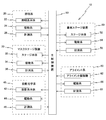
- FIG. 2 is a block diagram showing an input / output relationship of a main controller that mainly constitutes a control system of the liquid crystal exposure apparatus of FIG. 1.
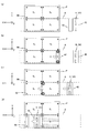
- FIGS. 3A to 3D are views (No. 1 to No. 4) for explaining the operation of the liquid crystal exposure apparatus during the exposure operation.
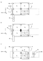
- FIGS. 4A to 4C are views (Nos. 5 to 7) for explaining the operation of the liquid crystal exposure apparatus during the exposure operation. It is a figure for demonstrating the structure of the alignment system which concerns on a 1st modification. It is a figure for demonstrating the structure of the alignment system which concerns on a 2nd modification.
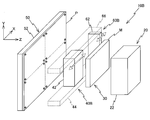
- FIG. 1 shows a conceptual diagram of a liquid crystal exposure apparatus 10 according to an embodiment.
- the liquid crystal exposure apparatus 10 employs a step-and-scan method in which a rectangular (square) glass substrate P (hereinafter simply referred to as a substrate P) used in, for example, a liquid crystal display device (flat panel display) is an exposure object.
- a projection exposure apparatus a so-called scanner.
- the liquid crystal exposure apparatus 10 includes an illumination system 20 that irradiates illumination light IL that is an energy beam for exposure, and a projection optical system 40.
- the direction parallel to the optical axis of the illumination light IL applied to the substrate P from the illumination system 20 via the projection optical system 40 is referred to as the Z-axis direction
- the X-axis is orthogonal to each other in a plane orthogonal to the Z-axis.
- the explanation will be given with the Y axis set. In the coordinate system of the present embodiment, it is assumed that the Y axis is substantially parallel to the direction of gravity. Therefore, the XZ plane is substantially parallel to the horizontal plane.
- the rotation (tilt) direction around the Z axis will be described as the ⁇ z direction.
- a plurality of exposure target areas (which will be referred to as partition areas or shot areas as appropriate) are set on one substrate P, and a mask pattern is sequentially transferred to the plurality of shot areas. Is done.
- partition areas or shot areas as appropriate
- a mask pattern is sequentially transferred to the plurality of shot areas.
- the liquid crystal exposure apparatus 10 performs a so-called step-and-scan exposure operation.
- the mask M and the substrate P are substantially stationary, and the illumination system 20 and the projection optical system. 40 (illumination light IL) moves relative to the mask M and the substrate P with a long stroke in the X-axis direction (referred to as the scanning direction as appropriate) (see the white arrow in FIG. 1).
- the mask M is stepped with a predetermined stroke in the X-axis direction
- the substrate P is stepped with a predetermined stroke in the Y-axis direction (see FIGS. 1 black arrow).
- FIG. 2 is a block diagram showing the input / output relationship of the main control device 90 that controls the components of the liquid crystal exposure apparatus 10 in an integrated manner.
- the liquid crystal exposure apparatus 10 includes an illumination system 20, a mask stage apparatus 30, a projection optical system 40, a substrate stage apparatus 50, an alignment system 60, and the like.
- the illumination system 20 includes an illumination system body 22 including a light source (for example, a mercury lamp) of illumination light IL (see FIG. 1).
- the main controller 90 scans the illumination system main body 22 with a predetermined long stroke in the X-axis direction by controlling the drive system 24 including, for example, a linear motor.
- the main controller 90 obtains position information of the illumination system body 22 in the X-axis direction via the measurement system 26 including, for example, a linear encoder, and performs position control of the illumination system body 22 based on the position information.
- g-line, h-line, i-line or the like is used as the illumination light IL.
- the mask stage apparatus 30 includes a stage main body 32 that holds the mask M.
- the stage main body 32 is configured to be appropriately step-movable in the X-axis direction and the Y-axis direction by a drive system 34 including, for example, a linear motor.
- the main controller 90 controls the drive system 34 to step-drive the stage body 32 in the X-axis direction. Further, as will be described later, during the step operation for changing the scanning exposure region (position) in the Y-axis direction in the partition region to be exposed, the main controller 90 controls the drive system 34 to control the stage.
- the main body 32 is step-driven in the Y-axis direction.
- the drive system 34 can also appropriately finely drive the mask M in the direction of three degrees of freedom (X, Y, ⁇ z) in the XY plane during an alignment operation described later.
- the position information of the mask M is obtained by a measurement system 36 including a linear encoder, for example.
- the projection optical system 40 includes a projection system main body 42 including an optical system that forms an erect image of a mask pattern on a substrate P (see FIG. 1) in the same magnification system.
- the projection system main body 42 is disposed in a space formed between the substrate P and the mask M (see FIG. 1).
- the main controller 90 controls the drive system 44 including, for example, a linear motor, so that the projection system main body 42 has a predetermined length in the X-axis direction so as to synchronize with the illumination system main body 22. Scan drive with stroke.
- the main controller 90 obtains position information in the X-axis direction of the projection system main body 42 via the measurement system 46 including, for example, a linear encoder, and controls the position of the projection system main body 42 based on the position information.
- the illumination light IL that has passed through the mask M passes through the projection optical system 40.
- a projection image (partial upright image) of the mask pattern in the illumination area IAM is formed in the irradiation area (exposure area IA) of the illumination light IL conjugate to the illumination area IAM on the substrate P.
- the scanning light exposure operation is performed when the illumination light IL (the illumination area IAM and the exposure area IA) moves relative to the mask M and the substrate P in the scanning direction. That is, in the liquid crystal exposure apparatus 10, the pattern of the mask M is generated on the substrate P by the illumination system 20 and the projection optical system 40, and the sensitive layer (resist layer) on the substrate P is exposed by the illumination light IL. The pattern is formed.
- the illumination area IAM generated on the mask M by the illumination system 20 includes a pair of rectangular areas separated in the Y-axis direction.
- the length in the Y-axis direction of one rectangular area is, for example, 1 in the length in the Y-axis direction of the pattern surface of the mask M (that is, the length in the Y-axis direction of each partition area set on the substrate P). / 4 is set.
- the distance between the pair of rectangular areas is set to, for example, 1/4 of the length of the pattern surface of the mask M in the Y-axis direction.
- the exposure area IA generated on the substrate P similarly includes a pair of rectangular areas spaced apart in the Y-axis direction.
- the illumination system main body 22 and the projection system main body 42 are required. There is an advantage that can be downsized. A specific example of the scanning exposure operation will be described later.
- the substrate stage apparatus 50 includes a stage body 52 that holds the back surface of the substrate P (the surface opposite to the exposure surface).
- the main controller 90 controls the drive system 54 including, for example, a linear motor to move the stage main body 52 to the Y-direction. Step drive in the axial direction.
- the drive system 54 can also minutely drive the substrate P in the direction of three degrees of freedom (X, Y, ⁇ z) in the XY plane during a substrate alignment operation described later.
- the position information of the substrate P (stage main body 52) is obtained by a measurement system 56 including, for example, a linear encoder.
- the alignment system 60 includes an alignment microscope 62.
- the alignment microscope 62 is arranged in a space formed between the substrate P and the mask M (position between the substrate P and the mask M with respect to the Z-axis direction), and the alignment mark Mk formed on the substrate P. (Hereinafter simply referred to as a mark Mk) and a mark (not shown) formed on the mask M are detected.
- a mark Mk is formed near each of the four corners of each partition area (for example, four for each partition area), and the mark on the mask M is marked via the projection optical system 40. It is formed at a position corresponding to Mk.
- the numbers and positions of the marks Mk and the marks of the mask M are not limited to this, and can be changed as appropriate. In each drawing, the mark Mk is shown larger than the actual size for easy understanding.
- the alignment microscope 62 is arranged on the + X side of the projection system main body 42.
- the alignment microscope 62 has a pair of detection visual fields (detection areas) separated in the Y-axis direction, and can simultaneously detect, for example, two marks Mk separated in the Y-axis direction in one partition area. It is like that.
- the alignment microscope 62 can simultaneously detect the mark formed on the mask M and the mark Mk formed on the substrate P (in other words, without changing the position of the alignment microscope 62). .
- the main controller 90 performs information on the relative displacement between the mark formed on the mask M and the mark Mk formed on the substrate P. Then, relative positioning of the substrate P and the mask M in the direction along the XY plane is performed so as to correct (cancel or reduce) the positional deviation.
- a mask detection unit for detecting (observing) the mark on the mask M and a substrate detection unit for detecting (observing) the mark Mk on the substrate P are integrally configured by a common housing or the like. And is driven by a drive system 66 through the common housing.
- the mask detection unit and the substrate detection unit may be configured by separate housings, and in that case, for example, the mask detection unit and the substrate detection unit are substantially equivalent by a common drive system 66. It is preferable to be configured so that it can move with operating characteristics.
- the main control device 90 drives the alignment microscope 62 with a predetermined long stroke in the X-axis direction by controlling a drive system 66 (see FIG. 2) including, for example, a linear motor. Further, the main controller 90 obtains position information of the alignment microscope 62 in the X-axis direction via a measurement system 68 including, for example, a linear encoder, and performs position control of the alignment microscope 62 based on the position information.
- the drive system 66 also includes, for example, a linear motor for driving the alignment microscope 62 in the Y-axis direction.
- the alignment microscope 62 of the alignment system 60 and the projection system main body 42 of the above-described projection optical system 40 are physically (mechanically) independent (separated) elements, and the main controller 90 (see FIG. 2).
- the driving system 66 that drives the alignment microscope 62 and the driving system 44 that drives the projection system main body 42 are related to driving in the X-axis direction. For example, a part of a linear motor, a linear guide, etc. is shared, and the drive characteristics of the alignment microscope 62 and the projection system main body 42 or the control characteristics of the main controller 90 are configured to be substantially equal. Yes.
- a magnetic body unit for example, a permanent magnet
- the alignment unit 62 and the projection system main body 42 each independently have a coil unit that is a mover, and the main controller 90 (see FIG. 2) individually supplies power to the coil unit.
- the drive (speed and position) of the alignment microscope 62 in the X-axis direction and the drive (speed and position) of the projection system main body 42 in the X-axis direction are controlled independently.
- the main controller 90 can change (arbitrarily change) the interval (distance) between the alignment microscope 62 and the projection system main body 42 in the X-axis direction.
- the main controller 90 can also move the alignment microscope 62 and the projection system main body 42 at different speeds in the X-axis direction.
- Main controller 90 detects a plurality of marks Mk formed on substrate P using alignment microscope 62, and based on the detection results (position information of the plurality of marks Mk), Arrangement information (including information on the position (coordinate value), shape, etc. of the partition area) of the partition area in which the mark Mk to be detected is formed is calculated by an enhanced global alignment (EGA) method.
- ESA enhanced global alignment
- the main controller 90 uses the alignment microscope 62 arranged on the + X side of the projection system main body 42 prior to the scanning exposure operation to at least expose the object.
- the position information of, for example, four marks Mk formed in the divided area is detected, and the arrangement information of the divided areas is calculated.
- the main controller 90 performs precise positioning (substrate alignment operation) in the three degrees of freedom in the XY plane of the substrate P based on the calculated arrangement information of the partition areas to be exposed, the illumination system 20, and the projection
- the optical system 40 is controlled as appropriate to perform a scanning exposure operation (mask pattern transfer) on the target partition region.
- a measurement system 46 for obtaining position information of the projection system main body 42 included in the projection optical system 40 and a measurement system 68 for obtaining position information of the alignment microscope 62 included in the alignment system 60 will be described.
- a typical configuration will be described.
- the liquid crystal exposure apparatus 10 has a guide 80 for guiding the projection system main body 42 in the scanning direction.
- the guide 80 is made of a member extending in parallel with the scanning direction.
- the guide 80 also has a function of guiding the movement of the alignment microscope 62 in the scanning direction.
- the guide 80 is illustrated between the mask M and the substrate P. Actually, however, the guide 80 is disposed at a position avoiding the optical path of the illumination light IL in the Y-axis direction. .
- a scale 82 including a reflective diffraction grating having a periodic direction at least in a direction parallel to the scanning direction (X-axis direction) is fixed to the guide 80.
- the projection system main body 42 has a head 84 disposed so as to face the scale 82.
- the scale 82 and the head 84 form an encoder system that constitutes a measurement system 46 (see FIG. 2) for obtaining position information of the projection system main body 42.
- the alignment microscope 62 has a head 86 that is disposed to face the scale 82.
- the scale 82 and the head 86 form an encoder system that constitutes a measurement system 68 (see FIG. 2) for obtaining positional information of the alignment microscope 62.
- the heads 84 and 86 respectively irradiate the scale 82 with a beam for encoder measurement, receive a beam through the scale 82 (a reflected beam by the scale 82), and based on the light reception result, the scale 82. Relative position information can be output.
- the scale 82 constitutes the measurement system 46 (see FIG. 2) for obtaining the position information of the projection system main body 42, and the measurement system 68 (for obtaining the position information of the alignment microscope 62). (See FIG. 2). That is, the position control of the projection system main body 42 and the alignment microscope 62 is performed based on a common coordinate system (measurement axis) set by the diffraction grating formed on the scale 82.
- the drive system 44 (see FIG. 2) for driving the projection system main body 42 and the drive system 66 (see FIG. 2) for driving the alignment microscope 62 may have some common elements. It may be constituted by completely independent elements.
- the encoder system constituting the measuring systems 46 and 68 may be a linear (1 DOF) encoder system whose length measuring axis is only in the X-axis direction (scanning direction), for example. There may be more measuring axes.
- the rotation amounts of the projection system main body 42 and the alignment microscope 62 in the ⁇ z direction may be obtained by arranging a plurality of heads 84 and 86 at predetermined intervals in the Y-axis direction.
- an XY two-dimensional diffraction grating may be formed on the scale 82, and a 3DOF encoder system having measurement axes in the three degrees of freedom in the X, Y, and ⁇ z directions may be used.
- the freedom of the projection system main body 42 and the alignment microscope 62 can be reduced. Position information in the degree direction may be obtained.
- the projection system main body 42 and the alignment microscope 62 are respectively disposed in the space between the substrate P and the mask M, and their positions in the Y-axis direction are substantially the same.
- the movable range partially overlaps.
- the main controller 90 performs drive control (collision avoidance control) that does not cause the projection system main body 42 and the alignment microscope 62 to collide, for example, when the projection system main body 42 is driven in the X-axis direction during a scanning exposure operation.
- the main controller 90 performs drive control so that the projection system main body 42 and the alignment microscope 62 are not simultaneously disposed in the same position in the X-axis direction. For example, from the movement path (movement range) of the projection system main body 42, Retraction control for retracting the alignment microscope 62 is performed.
- FIGS. 3 (a) to 4 (c) an example of the operation of the liquid crystal exposure apparatus 10 during the scanning exposure operation including the collision avoidance control (retraction control) of the alignment microscope 62 will be described with reference to FIGS. 3 (a) to 4 (c).
- the following exposure operations are performed under the control of the main controller 90 (not shown in FIGS. 3A to 4C, see FIG. 2).
- divided areas exposed order is the first (hereinafter referred to as the first shot area S 1) is set on the -X side and -Y side of the substrate P.
- the rectangular area denoted by reference symbol A indicates the movement range (movement path) of the projection system main body 42 during the scanning exposure operation.
- the movement range A of the projection system main body 42 is set, for example, mechanically and / or electrically.
- the reference numerals S 2 to S 4 given to the partition areas on the substrate P indicate that the exposure areas are the second to fourth shot areas, respectively.
- the projection system main body 42, and the alignment microscope 62 are disposed on the -X side of the first shot area S 1 in a plan view.
- the projection system main body 42 and the alignment microscope 62 are arranged close to each other in the X-axis direction.
- the main controller 90 drives the alignment microscope 62 in the + X direction as shown in FIG.
- the main controller 90 controls the projection system main body 42.
- the main control device 90 while moving the alignment microscope 62 in the + X direction, of the first shot area S 1, after for example detects the four marks Mk (see heavy line circle in FIG. 3 (b)), the main controller 90, based on the mark detection result to calculate a first sequence information of the shot areas S 1.
- the main controller 90 starts accelerating the projection system main body 42 in the + X direction independently of the alignment microscope 62 in parallel with the mark detection operation by the alignment microscope 62.
- the main controller 90 for example, just before the mark Mk of the first shot area S 1 of the + X side is detected by the alignment microscope 62, to initiate acceleration in the + X direction of the projection system main body 42.
- the movement of the projection system main body 42 in the + X direction is started after the movement of the alignment microscope 62 in the + X direction (mark detection operation).
- the distance (distance) in the X-axis direction between the projection system main body 42 and the alignment microscope 62 is wider than the initial position (before the start of the alignment operation) shown in FIG.
- the first shot area S 1 for example, completed four marks Mk detection, it is desirable that the sequence information of the first shot area S 1 based on the four marks are required.
- the main controller 90 synchronizes the projection system main body 42 and the illumination system main body 22 of the illumination system 20 (not shown in FIG. 3D, see FIG. 1) + X and driven in the direction, performs first scanning exposure for the first shot area S 1.
- the main control unit 90 can be based on the detection result of the mark in the fourth shot area S 4, and updates the first sequence information of the shot areas S 1.
- the sequence information based only on the four marks Mk provided in the first shot area S 1 than determined it is possible to obtain the sequence information in consideration of the statistical trend over a wide range, it is possible to improve the alignment accuracy for the first shot area S 1.
- the main controller 90 controls the illumination system 20 while controlling the minute position of the substrate P according to the calculation result of the array information, and the illumination light IL is not shown in the mask M (not shown in FIG. 3D). And a part of the mask pattern is formed in the exposure area IA generated on the substrate P by the illumination light IL.
- the illumination area IAM (see FIG. 1) generated on the mask M and the exposure area IA generated on the substrate P are a pair of rectangular areas separated in the Y-axis direction. Therefore, the pattern image of the mask M transferred to the substrate P by one scanning exposure operation is a band-like region extending in the X-axis direction and separated from the Y-axis direction (of the total area of one partition region). Half area).
- the main controller 90 performs control to retract the alignment microscope 62 from the movement range A.
- the main controller 90 drives the alignment microscope 62 in the ⁇ Y direction (downward) with respect to the substrate P to ⁇ Y in the movement range A of the projection system main body 42. Evacuate to the side.
- the projection system main body 42 passes through the + Y side (upward) of the alignment microscope 62 without colliding with the alignment microscope 62.
- the alignment microscope 62 is driven into the movement range A so that the projection system main body 42 and the alignment microscope 62 are arranged close to each other at a position where they are not in contact with each other. Therefore, the distance between the projection system main body 42 and the alignment microscope 62 in the X-axis direction is the time before the start of the scanning exposure operation or after the end of the scanning exposure operation (in other words, the projection system main body 42 is in the X-axis direction). Before starting acceleration or after completing deceleration).
- main controller 90 performs step movement of substrate P and mask M in the ⁇ Y direction as shown in FIG. 4B for the second scanning exposure operation of first shot region S 1 (FIG. 4B). 4 (b) black arrow).
- the step movement amount of the substrate P at this time is, for example, 1/4 of the length of one partition region in the Y-axis direction.
- the step is performed so that the relative positional relationship between the substrate P and the mask M is not changed (or the relative positional relationship can be corrected). It is preferable to move.
- the main controller 90 performs the scanning exposure operation of the second projection system first shot by driving the main body 42 in the -X direction area S 1 (backward).
- the mask pattern transferred by the first scanning exposure operation a mask pattern transferred by the second time of the scanning exposure operation is joined together with the first shot in region S 1, the overall pattern of the mask M It is transferred to the first shot area S 1.
- the main controller 90 returns the alignment microscope 62 from the retracted position to the movement range A of the projection system main body 42 and follows the projection system main body 42 to drive in the ⁇ X direction. As shown in FIG.
- main controller 90 returns alignment microscope 62 once retracted to -X side of projection system main body 42, and corresponds to FIGS. 3 (a) to 3 (d) and FIG. 4 (a).
- the drive control may be performed so as to perform the operation (however, the operation in which the movement in the X-axis direction is reversed (reverse sign)).
- the main controller 90 moves the substrate P to ⁇ Y in order to perform the scanning exposure operation on the second shot area S 2 (the partitioned area on the + Y side of the first shot area S 1 ). direction moved stepwise to oppose the second shot area S 2 and the mask M have. Scanning exposure operation for the second shot area S 2 (including the save operation of the alignment microscope 62) will be omitted because it is identical to the scanning exposure operation for the first shot area S 1 described above. Thereafter, the main controller 90 performs the scanning exposure operation on the third and fourth shot regions S 3 and S 4 while appropriately performing at least one of the X step operation of the mask M and the Y step operation of the substrate P.
- the main controller 90 similarly performs retraction control of the alignment microscope 62.
- the sequence information of the divided areas may be using the position information of the mark obtained on exposing the earlier defined areas.
- it may be utilized first shot area S 1 of the alignment measurement results described above (EGA result of the calculation).
- a mask M fourth shot area S 4 are three degrees of freedom in the XY plane on the basis of the marks of the respective two points between the mark Mk mark and the substrate P of the mask M ( It is only necessary to measure the positional deviation in the X, Y, ⁇ z) direction, and the time required for the alignment of the fourth shot region S4 can be substantially shortened.
- the drive control (position and speed) in the scanning direction (X-axis direction) of the alignment microscope 62 and the projection system main body 42 can be controlled independently.
- the mark Mk Prior to the movement (acceleration) of the system main body 42 in the scanning direction, the mark Mk can be detected using the alignment microscope 62, and the projection system main body 42 can be obtained before completing the detection of all the required marks Mk.
- the scanning direction that is, scanning exposure operation
- a series of processing time (tact time) required for the exposure processing of the substrate P can be reduced.
- the alignment microscope 62 and the projection system main body 42 can be arranged close to each other. Therefore, the apparatus size (footprint of the exposure apparatus) necessary for scanning exposure in the X-axis direction can be suppressed. Further, since the alignment microscope 62 can be retracted from the movement range A of the projection system main body 42 during the scanning exposure operation, collision between the alignment microscope 62 and the projection system main body 42 can be avoided.
- the illumination system 20, the mask stage device 30, the projection optical system 40, the substrate stage device 50, and the alignment system 60 may be modularized.
- the illumination system 20 is called the illumination system module 12M
- the mask stage device 30 is called the mask stage module 14M
- the projection optical system 40 is called the projection optical system module 16M
- the substrate stage device 50 is called the substrate stage module 18M
- the alignment system 60 is called the alignment system module 20M.
- each module 12M to 20M they are placed on the corresponding bases 28A to 28E so as to be physically independent of each other.
- an arbitrary (one or a plurality) of the modules 12M to 20M (the substrate stage module 18M as an example in FIG. 10) is replaced with another module. Can be replaced independently of the module. At this time, the module to be replaced is exchanged integrally with the bases 28A to 28E (the base 28E in FIG. 10) that supports the modules.
- the modules 12M to 20M (and the bases 28A to 28E supporting the modules) to be replaced move in the X-axis direction along the floor 26 surface. Therefore, for example, wheels or an air caster device may be provided on the bases 28A to 28E so that the bases 28A to 28E can be easily moved on the floor 26, for example.
- an arbitrary module among the modules 12M to 20M can be easily separated from other modules, so that it is excellent in maintainability.
- the substrate stage module 18M is separated from the other elements by moving in the + X direction (the back side of the drawing) with respect to the other elements (such as the projection optical system module 16M) together with the gantry 28E.
- the moving direction of the module to be moved (and the gantry) is not limited to this, and may be, for example, the ⁇ X direction (front of the page) or the + Y direction (upward on the page). good.
- a positioning device may be provided to ensure position reproducibility after installation on the floor 26 of each gantry 28A to 28E.
- the positioning device may be provided on each of the gantry 28A to 28E, or the installation position of each of the gantry 28A to 28E by cooperation of a member provided on each of the gantry 28A to 28E and a member provided on the floor 26. May be configured to be reproduced.
- the liquid crystal exposure apparatus 10 of the present embodiment has a configuration in which the modules 12M to 20M can be separated independently, the modules 12M to 20M can be individually upgraded.
- the upgrade refers to, for example, an upgrade to cope with an increase in the size of the substrate P to be exposed, and the modules 12M to 20M are replaced with modules having the same performance but with improved performance. This includes cases where
- the substrate stage module 18M of the liquid crystal exposure apparatus 10 is upgraded in response to an increase in the size of the substrate P, as shown in FIG. 10, a substrate stage module 18AM newly inserted instead of the substrate stage module 18M is used.
- the gantry 28G that supports the substrate stage module 18AM changes in the X-axis and / or Y-axis direction dimensions, but the Z-axis direction dimension does not change substantially.
- the dimension in the Z-axis direction of the mask stage module 14M is not substantially changed by the upgrade corresponding to the increase in the size of the mask M.
- the number of illumination optical systems included in the illumination system module 12M and the number of projection lens modules included in the projection optical system module 16M are increased.
- each of the illumination system module 12M and the projection optical system module 16M can be upgraded.
- the illumination system module and the projection optical system module (not shown) after the upgrade only change the dimensions in the X-axis and / or Y-axis direction compared to before the upgrade, and the dimensions in the Z-axis direction do not substantially change. .
- the bases 28A to 28E that support the modules 12M to 20M and the bases that support the upgraded modules are supported).
- the gantry 28G is sized in the Z-axis direction.
- scaling means that the dimensions in the Z-axis direction are the same for the base before and after the replacement, that is, the dimensions in the Z-axis direction of the base supporting the module having the same function are substantially constant. It means that.
- the dimensions in the Z-axis direction of each of the mounts 28A to 28E are made constant, it is possible to reduce the time for designing each module.
- the illumination system module 12M, the mask stage module 14M, and the projection optical system module Each module of 16M and the substrate stage module 18M can be installed in series on the floor 26 surface. As described above, since each module does not have its own weight, for example, the substrate stage device, the projection optical system, the mask stage device, and the illumination system corresponding to each module are stacked in the direction of gravity. Unlike the conventional exposure apparatus, it is not necessary to provide a high-rigidity main frame (body) that supports each element.
- each said module is a structure arrange
- the alignment microscope 62 performs the retreat operation by moving to the ⁇ Y side with respect to the movement range A of the projection system main body 42, but retreats outside the movement range A of the projection system main body 42.
- the retracting direction of the alignment microscope 62 is not limited to this.
- the direction parallel to the scanning direction with respect to the movement range A of the projection system main body 42 (X-axis) Direction).
- the retraction direction of the alignment microscope 62 may be, for example, on the + Y (up) side with respect to the movement range A of the projection system main body 42, on the + Z side (mask side), or ⁇ It may be on the Z side (substrate side).
- the alignment microscope 62 performs the retreat operation by moving in a direction orthogonal to the traveling direction of the projection system main body 42 or in a parallel direction.
- the moving direction of the alignment microscope 62 during the retraction operation is not limited to this, and may be the ⁇ z direction (or other rotational direction) as in the second modification example shown in FIG. If the control for retracting the alignment microscope 62 in a direction other than the X-axis direction is performed, the relative positional relationship between the projection system main body 42 and the alignment microscope 62 in the Y-axis direction may be different from the initial position.
- the main controller 90 performs calibration related to the relative position (relative coordinates) between the projection system main body 42 and the alignment microscope 62 every time the alignment microscope 62 is retracted.
- the retraction control of the alignment microscope 62 is performed at a position not on the substrate P.
- the position on the substrate P that is, the position of the alignment microscope 62 in the Y-axis direction.
- the position in the X-axis direction, the position in the Y-axis direction of the substrate P, and the position in the X-axis direction may be overlapped.
- the drive system 24 for driving the illumination system body 22 of the illumination system 20 and the drive system 34 for driving the stage body 32 of the mask stage apparatus 30 are used.
- the case where each of the drive systems 66 (see FIG. 2) includes a linear motor has been described.
- the type of actuator is not limited to this, and can be changed as appropriate.
- a feed screw (ball screw) device, a belt It is possible to use various actuators such as braking system appropriately.
- the projection system main body 42 and the alignment microscope 62 share a part of the drive system in the scanning direction (for example, a linear motor, a guide, etc.) If the projection system main body 42 and the alignment microscope 62 can be driven individually, the present invention is not limited to this.
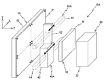
- a drive system 66 for driving the alignment microscope 62 and a drive system 44 for driving the projection system main body 42 of the projection optical system 40 may be configured completely independently. That is, like the exposure apparatus 10A shown in FIG. 8, the projection optical system main body 42 included in the projection optical system 40A and the alignment microscope 62 included in the alignment system 60A are arranged so that the Y positions do not overlap each other.
- a drive system 66 (including a linear motor, a guide, etc.) for driving the alignment microscope 62 and a drive system 44 (eg, including a linear motor, a guide, etc.) for driving the projection system main body 42 are completely provided. It can be set as an independent structure. In this case, before the start of the scanning exposure operation for the partitioned area to be exposed, the substrate P is moved stepwise (reciprocated) in the Y-axis direction to measure alignment of the partitioned area. Further, like the exposure apparatus 10B shown in FIG. 9, the alignment system 60B includes a drive system 44 (including a linear motor, a guide, and the like) for driving the projection optical system main body 42 of the projection optical system 40B. The drive system 44 and the drive system 66 are completely independent by arranging the Y positions so as not to overlap with a drive system 66 (including a linear motor, a guide, etc.) for driving the alignment microscope 62. It can also be.
- Measurement system 36 measurement system 46 for measuring the position of projection optical system main body 42 of projection optical system 40, measurement system 56 for measuring the position of stage main body 52 of substrate stage apparatus 50, and alignment system 60.
- the type of measurement system for measuring the position of the stage main body 52 and the alignment microscope 62 is not limited to this, and can be changed as appropriate.
- an optical interferometer or can be used as appropriate various measuring systems such as a linear encoder and the measurement system using a combination of optical interferometer.
- a pair of movable alignment microscopes 62 having a pair of detection visual fields are arranged on the + X side of the projection system main body 42.
- the number of microscopes is not limited to this.
- the alignment microscopes 62 may be arranged on the + X side and the ⁇ X side (one side and the other side in the scanning direction) of the projection system main body 42, respectively.
- the mark Mk is placed using the ⁇ X side alignment microscope 62.
- the next scanning exposure of the first shot area S 1 may be performed scanning exposure of the fourth shot area S 4.
- the first and fourth shot regions S 1 it can be scanned exposing the S 4 sequentially.
- the mark Mk is formed in each partition area (first to fourth shot areas S 1 to S 4 ).
- the present invention is not limited to this, and an area (so-called scribe) between adjacent partition areas is not limited thereto. Line).
- a pair of illumination area IAM and exposure area IA spaced apart in the Y-axis direction are generated on the mask M and the substrate P (see FIG. 1), but the shapes of the illumination area IAM and exposure area IA
- the length is not limited to this and can be changed as appropriate.
- the length of the illumination area IAM and the exposure area IA in the Y-axis direction may be equal to the pattern surface of the mask M and the length of one partition area on the substrate P in the Y-axis direction, respectively. In this case, the transfer of the mask pattern is completed with a single scanning exposure operation for each partitioned region.
- the illumination area IAM and the exposure area IA are one area whose length in the Y-axis direction is half the length in the Y-axis direction of one partition area on the pattern surface of the mask M and the substrate P, respectively. Also good. In this case, similarly to the above-described embodiment, it is necessary to perform the scanning exposure operation twice for one partitioned area and perform the joint exposure.
- the joint portion means a joint portion between an area exposed by the forward scanning exposure (area where the pattern is transferred) and an area exposed by the backward scanning exposure (the area where the pattern is transferred). To do.
- the mark Mk in the vicinity of the joint portion the mark Mk may be formed on the substrate P in advance, or an exposed pattern may be used as the mark Mk.
- the wavelength of the light source used in the illumination system 20 and the illumination light IL irradiated from this light source is not specifically limited,
- ArF excimer laser light wavelength 193 nm
- KrF excimer laser light Ultraviolet light having a wavelength of 248 nm
- vacuum ultraviolet light such as F 2 laser light (wavelength 157 nm) may be used.
- the illumination system main body 22 including the light source is driven in the scanning direction.
- the present invention is not limited to this.
- the light source is fixed. Only the illumination light IL may be scanned in the scanning direction.
- the illumination area IAM and the exposure area IA are formed in a strip shape extending in the Y-axis direction.
- the present invention is not limited to this.
- a plurality of regions arranged in a staggered pattern may be combined.
- the mask M and the substrate P are arranged so as to be orthogonal to the horizontal plane (so-called vertical arrangement).
- the present invention is not limited to this, and the mask M and the substrate P are parallel to the horizontal plane. It may be arranged.
- the optical axis of the illumination light IL is substantially parallel to the direction of gravity.
- fine positioning in the XY plane of the substrate P was performed in accordance with the alignment measurement result during the scanning exposure operation.
- the surface of the substrate P before the scanning exposure operation (or in parallel with the scanning exposure operation). Position information may be obtained, and surface position control (so-called autofocus control) of the substrate P may be performed during the scanning exposure operation.
- the use of the exposure apparatus is not limited to an exposure apparatus for liquid crystal that transfers a liquid crystal display element pattern onto a square glass plate.
- an exposure apparatus for manufacturing an organic EL (Electro-Luminescence) panel, a semiconductor The present invention can be widely applied to an exposure apparatus for manufacturing, an exposure apparatus for manufacturing a thin film magnetic head, a micromachine, a DNA chip, and the like.
- an exposure apparatus for manufacturing a thin film magnetic head a micromachine, a DNA chip, and the like.
- the present invention can also be applied to an exposure apparatus that transfers a circuit pattern.
- the object to be exposed is not limited to the glass plate, but may be another object such as a wafer, a ceramic substrate, a film member, or a mask blank.
- the thickness of the substrate is not particularly limited, and includes, for example, a film-like (flexible sheet-like member).
- the exposure apparatus of the present embodiment is particularly effective when a substrate having a side length or diagonal length of 500 mm or more is an exposure target.
- the substrate to be exposed is a flexible sheet, the sheet may be formed in a roll shape. In this case, the partition area to be exposed can be easily changed (stepped) with respect to the illumination area (illumination light) by rotating (winding) the roll regardless of the step operation of the stage device. .
- the step of designing the function and performance of the device the step of producing a mask (or reticle) based on this design step, and the step of producing a glass substrate (or wafer)
- the above-described exposure method is executed using the exposure apparatus of the above embodiment, and a device pattern is formed on the glass substrate. Therefore, a highly integrated device can be manufactured with high productivity. .
- the exposure apparatus and method of the present invention are suitable for scanning exposure of an object.
- the manufacturing method of the flat panel display of this invention is suitable for production of a flat panel display.
- the device manufacturing method of the present invention is suitable for the production of micro devices.
- DESCRIPTION OF SYMBOLS 10 ... Liquid crystal exposure apparatus, 20 ... Illumination system, 30 ... Mask stage apparatus, 40 ... Projection optical system, 50 ... Substrate stage apparatus, 60 ... Alignment system, M ... Mask, P ... Substrate.
Landscapes
- Physics & Mathematics (AREA)
- General Physics & Mathematics (AREA)
- Engineering & Computer Science (AREA)
- Nonlinear Science (AREA)
- Multimedia (AREA)
- Life Sciences & Earth Sciences (AREA)
- Chemical & Material Sciences (AREA)
- Crystallography & Structural Chemistry (AREA)
- Sustainable Development (AREA)
- Optics & Photonics (AREA)
- Health & Medical Sciences (AREA)
- Environmental & Geological Engineering (AREA)
- Epidemiology (AREA)
- Public Health (AREA)
- Exposure And Positioning Against Photoresist Photosensitive Materials (AREA)
- Liquid Crystal (AREA)
- Container, Conveyance, Adherence, Positioning, Of Wafer (AREA)
Abstract
Description
Claims (52)
- 投影光学系を介して物体に照明光を照射し、前記物体に対して前記投影光学系を相対駆動させて走査露光する露光装置であって、
前記物体に設けられたマークを検出するマーク検出部と、
前記マーク検出部を駆動する第1駆動系と、
前記投影光学系を駆動する第2駆動系と、
前記投影光学系と前記マーク検出部とが互いに接触しないように前記第1及び第2駆動系を制御する制御装置と、を備える露光装置。 - 投影光学系を介して物体に照明光を照射し、前記物体に対して前記投影光学系を相対駆動させて走査露光する露光装置であって、
前記物体に設けられたマークを検出するマーク検出部と、
前記マーク検出部を駆動する第1駆動系と、
前記投影光学系を駆動する第2駆動系と、
前記走査露光において、前記投影光学系と前記マーク検出部との少なくとも一方が駆動するとき、前記投影光学系と前記マーク検出部との間隔を所定距離以上あけるように前記第1及び第2駆動系の少なくとも一方の駆動系を制御する制御装置と、を備える露光装置。 - 投影光学系を介して物体に照明光を照射し、前記物体に対して前記投影光学系を相対駆動させて走査露光動作を行う露光装置であって、
前記物体に設けられたマークを検出するマーク検出部と、
前記マーク検出部を駆動する第1駆動系と、
前記投影光学系を駆動する第2駆動系と、
前記走査露光動作中の少なくとも一部の動作において、前記投影光学系及び前記マーク検出部がそれぞれの異なる駆動速度で駆動するように前記第1及び第2駆動系を制御する制御装置と、を備える露光装置。 - 投影光学系を介して物体に照明光を照射し、前記物体に対して前記投影光学系を相対駆動させて走査露光する露光装置であって、
前記物体に設けられたマークを検出するマーク検出部と、
前記マーク検出部を駆動する第1駆動系と、
前記投影光学系を駆動する第2駆動系と、
前記投影光学系が駆動を停止する停止位置と前記マーク検出部が駆動を停止する停止位置とが重ならないように前記第1及び第2駆動系を制御する制御装置と、を備える露光装置。 - 投影光学系を介して物体に照明光を照射し、前記物体に対して前記投影光学系を相対駆動させて走査露光する露光装置であって、
前記物体に設けられたマークを検出するマーク検出部と、
前記マーク検出部を駆動する第1駆動系と、
前記投影光学系を駆動する第2駆動系と、
前記投影光学系の駆動開始タイミングと前記マーク検出部の駆動開始タイミングとを異ならせるように前記第1及び第2駆動系を制御する制御装置と、を備える露光装置。 - 投影光学系を介して物体に照明光を照射し、前記物体に対して前記投影光学系を相対駆動させて走査露光する露光装置であって、
前記物体に設けられたマークを検出するマーク検出部と、
前記走査露光において、互いの相対位置関係が変わらないように前記投影光学系と前記マーク検出部とを位置制御する制御装置と、を備える露光装置。 - 前記物体は、位置が異なる第1及び第2区画領域を少なくとも有し、
前記マーク検出部は、前記物体に対して前記投影光学系を相対駆動させる走査方向に関して、前記投影光学系の一方側に設けられた第1検出装置と前記投影光学系の他方側に設けられた第2検出装置とを有し、
前記制御装置は、前記第1区画領域に対する前記走査露光において、前記第1検出装置による前記マークの検出結果に基づいて前記投影光学系を前記一方側に駆動しつつ、前記第2検出装置を前記投影光学系に接触しないように前記第2区画領域の前記一方側へ駆動するように前記第1及び第2駆動系を制御する請求項1~6の何れか一項に記載の露光装置。 - 前記制御装置は、前記第2区画領域に対する前記走査露光において、前記第2検出装置による前記マークの検出結果に基づいて前記投影光学系を前記他方側に駆動するように前記第1及び第2駆動系を制御する請求項7に記載の露光装置。
- 前記制御装置は、前記走査露光を行う第1状態と前記走査露光の開始前または終了後の前記照明光を前記物体に照射しない第2状態とで、前記投影光学系と前記マーク検出部との間隔を異ならせる請求項1~8の何れか一項に記載の露光装置。
- 前記第1状態における前記間隔は、前記第2状態における前記間隔よりも広い請求項9に記載の露光装置。
- 前記第2状態における前記投影光学系及び前記マーク検出部は、前記投影光学系の光軸に平行な方向に関して前記物体とは重ならない位置にある請求項9又は10に記載の露光装置。
- 前記マーク検出部は、前記投影光学系の駆動可能範囲とは一部重ならない範囲を駆動する請求項1~11の何れか一項に記載の露光装置。
- 前記マーク検出部は、前記駆動可能範囲よりも広い範囲を駆動する請求項12に記載の露光装置。
- 前記制御装置は、前記マークを検出する動作を含むマーク検出動作と前記走査露光を含む走査露光動作との少なくとも一部の動作を並行して行うよう制御する請求項1~13の何れか一項に記載の露光装置。
- 前記マーク検出動作は、前記マーク検出部が前記マークを検出する位置へ移動する動作を含み、
前記走査露光動作は、前記走査露光の開始前の前記投影光学系の移動動作を含む請求項14に記載の露光装置。 - 前記制御装置は、前記マーク検出部を前記投影光学系が駆動する前記走査方向と前記走査方向に交差する方向との何れかの移動可能範囲から退避させる請求項7に記載の露光装置。
- 前記制御装置は、前記マーク検出部を前記投影光学系の前記移動可能範囲から退避させるために前記投影光学系の光軸と平行な方向を軸として回転させる請求項16に記載の露光装置。
- 前記マーク検出部は、前記走査方向に交差する方向に関して、前記照明光が照射される領域の長さよりも前記物体上に設けられた複数の前記マーク間の距離が長いマークを検出可能に設けられる請求項7に記載の露光装置。
- 前記物体は、前記前記走査方向に交差する方向に並んで設けられた第1及び第2区画領域を有し、
前記マーク検出部は、前記第2方向に関して、前記第1区画領域上の少なくとも1つの前記マークと前記第2区画領域上の少なくとも1つの前記マークとを同時に検出可能に設けられた請求項18に記載の露光装置。 - 投影光学系を介して物体に照明光を照射し、前記物体に対して前記投影光学系を第1方向に相対駆動して露光する露光動作により、所定パターンを前記物体上に形成する露光装置であって、
前記物体に設けられたマークを検出するマーク検出部と、
前記マーク検出部を前記第1方向に駆動する第1駆動系と、
前記投影光学系を、前記第1駆動系とは独立して前記第1方向に駆動する第2駆動系と、を備える露光装置。 - 前記投影光学系の光軸が水平面に平行であり、
前記物体は、前記照明光が照射される露光面が前記水平面に対して直交した状態で配置される請求項1~20の何れか一項に記載の露光装置。 - 前記マーク検出部と前記投影光学系は、互いに分離可能に配置される請求項21に記載の露光装置。
- 前記物体は、フラットパネルディスプレイ装置に用いられる基板である請求項1~22に記載の露光装置。
- 前記基板は、少なくとも一辺の長さ又は対角長が500mm以上である請求項23に記載の露光装置。
- 請求項1~24の何れか一項に記載の露光装置を用いて前記物体を露光することと、
露光された前記物体を現像することと、を含むフラットパネルディスプレイの製造方法。 - 請求項1~24の何れか一項に記載の露光装置を用いて前記物体を露光することと、
露光された前記物体を現像することと、を含むデバイス製造方法。 - 投影光学系を介して物体に照明光を照射し、前記物体に対して前記投影光学系を相対駆動させて走査露光する露光方法であって、
前記物体に設けられたマークをマーク検出部を用いて検出することと、
前記マーク検出部を第1駆動系を用いて駆動することと、
前記投影光学系を第2駆動系を用いて駆動することと、
前記投影光学系と前記マーク検出部とが互いに接触しないように前記第1及び第2駆動系を制御することと、を含む露光方法。 - 投影光学系を介して物体に照明光を照射し、前記物体に対して前記投影光学系を相対駆動させて走査露光する露光方法であって、
前記物体に設けられたマークをマーク検出部を用いて検出することと、
前記マーク検出部を第1駆動系を用いて駆動することと、
前記投影光学系を第2駆動系を用いて駆動することと、
前記走査露光において、前記投影光学系と前記マーク検出部との少なくとも一方が駆動するとき、前記投影光学系と前記マーク検出部との間隔を所定距離以上あけるように前記第1及び第2駆動系の少なくとも一方の駆動系を制御することと、を含む露光方法。 - 投影光学系を介して物体に照明光を照射し、前記物体に対して前記投影光学系を相対駆動させて走査露光する露光方法であって、
前記物体に設けられたマークをマーク検出部を用いて検出することと、
前記マーク検出部を第1駆動系を用いて駆動することと、
前記投影光学系を第2駆動系を用いて駆動することと、
前記走査露光動作中の少なくとも一部の動作において、前記投影光学系及び前記マーク検出部がそれぞれの異なる駆動速度で駆動するように前記第1及び第2駆動系を制御することと、を含む露光方法。 - 投影光学系を介して物体に照明光を照射し、前記物体に対して前記投影光学系を相対駆動させて走査露光する露光方法であって、
前記物体に設けられたマークをマーク検出部を用いて検出することと、
前記マーク検出部を第1駆動系を用いて駆動することと、
前記投影光学系を第2駆動系を用いて駆動することと、
前記投影光学系が駆動を停止する停止位置と前記マーク検出部が駆動を停止する停止位置とが重ならないように前記第1及び第2駆動系を制御することと、を含む露光方法。 - 投影光学系を介して物体に照明光を照射し、前記物体に対して前記投影光学系を相対駆動させて走査露光する露光方法であって、
前記物体に設けられたマークをマーク検出部を用いて検出することと、
前記マーク検出部を第1駆動系を用いて駆動することと、
前記投影光学系を第2駆動系を用いて駆動することと、
前記投影光学系の駆動開始タイミングと前記マーク検出部の駆動開始タイミングとを異ならせるように前記第1及び第2駆動系を制御することと、を含む露光方法。 - 投影光学系を介して物体に照明光を照射し、前記物体に対して前記投影光学系を相対駆動させて走査露光する露光方法であって、
前記物体に設けられたマークをマーク検出部を用いて検出することと、
前記走査露光において、互いの相対位置関係が変わらないように前記投影光学系の位置と前記マーク検出部の位置とを制御することと、を含む露光方法。 - 前記物体は、位置が異なる第1及び第2区画領域を少なくとも有し、
前記マーク検出部は、前記物体に対して前記投影光学系を相対駆動させる走査方向に関して、前記投影光学系の一方側に設けられた第1検出装置と前記投影光学系の他方側に設けられた第2検出装置とを有し、
前記制御することでは、前記第1区画領域に対する前記走査露光において、前記第1検出装置による前記マークの検出結果に基づいて前記投影光学系を前記一方側に駆動しつつ、前記第2検出装置を前記投影光学系に接触しないように前記第2区画領域の前記一方側へ駆動するように前記第1及び第2駆動系を制御する請求項27~32の何れか一項に記載の露光方法。 - 前記制御することでは、前記第2区画領域に対する前記走査露光において、前記第2検出装置による前記マークの検出結果に基づいて前記投影光学系を前記他方側に駆動するように前記第1及び第2駆動系を制御する請求項33に記載の露光方法。
- 前記制御することでは、前記走査露光を行う第1状態と前記走査露光の開始前または終了後の前記照明光を前記物体に照射しない第2状態とで、前記投影光学系と前記マーク検出部との間隔を異ならせる請求項27~34の何れか一項に記載の露光方法。
- 前記第1状態における前記間隔は、前記第2状態における前記間隔よりも広い請求項35に記載の露光方法。
- 前記第2状態における前記投影光学系及び前記マーク検出部は、前記投影光学系の光軸に平行な方向に関して前記物体とは重ならない位置にある請求項35又は36に記載の露光方法。
- 前記マーク検出部は、前記投影光学系の駆動可能範囲とは一部重ならない範囲を駆動する請求項27~37の何れか一項に記載の露光方法。
- 前記マーク検出部は、前記駆動可能範囲よりも広い範囲を駆動する請求項38に記載の露光方法。
- 前記制御することでは、前記マークを検出する動作を含むマーク検出動作と前記走査露光を含む走査露光動作との少なくとも一部の動作を並行して行うよう制御する請求項27~39の何れか一項に記載の露光方法。
- 前記マーク検出動作は、前記マーク検出部が前記マークを検出する位置へ移動する動作を含み、
前記走査露光動作は、前記走査露光の開始前の前記投影光学系の移動動作を含む請求項40に記載の露光方法。 - 前記制御することでは、前記マーク検出部を前記投影光学系が駆動する前記走査方向と前記走査方向に交差する方向との何れかの移動可能範囲から退避させる請求項33に記載の露光方法。
- 前記制御することでは、前記マーク検出部を前記投影光学系の前記移動可能範囲から退避させるために前記投影光学系の光軸と平行な方向を軸として回転させる請求項42に記載の露光方法。
- 前記マーク検出部は、前記走査方向に交差する方向に関して、前記照明光が照射される領域の長さよりも前記物体上に設けられた複数の前記マーク間の距離が長いマークを検出可能に設けられる請求項33に記載の露光方法。
- 前記物体は、前記前記走査方向に交差する方向に並んで設けられた第1及び第2区画領域を有し、
前記マーク検出部は、前記第2方向に関して、前記第1区画領域上の少なくとも1つの前記マークと前記第2区画領域上の少なくとも1つの前記マークとを同時に検出可能に設けられた請求項44に記載の露光方法。 - 投影光学系を介して物体に照明光を照射し、前記物体に対して前記投影光学系を第1方向に相対駆動して露光する露光動作により、所定パターンを前記物体上に形成する露光方法であって、
前記物体に設けられたマークをマーク検出部を用いて検出することと、
前記マーク検出部を前記第1方向に第1駆動系を用いて駆動することと、
前記投影光学系を、前記第1駆動系とは独立して前記第1方向に第2駆動系を用いて駆動することと、を含む露光方法。 - 前記投影光学系の光軸が水平面に平行であり、
前記物体は、前記照明光が照射される露光面が前記水平面に対して直交した状態で配置される請求項27~46の何れか一項に記載の露光方法。 - 前記マーク検出部と前記投影光学系は、互いに分離可能に配置される請求項47に記載の露光方法。
- 前記物体は、フラットパネルディスプレイ装置に用いられる基板である請求項27~48の何れか一項に記載の露光方法。
- 前記基板は、少なくとも一辺の長さ又は対角長が500mm以上である請求項49に記載の露光方法。
- 請求項27~50の何れか一項に記載の露光方法を用いて前記物体を露光することと、
露光された前記物体を現像することと、を含むフラットパネルディスプレイの製造方法。 - 請求項27~50の何れか一項に記載の露光方法を用いて前記物体を露光することと、
露光された前記物体を現像することと、を含むデバイス製造方法。
Priority Applications (4)
| Application Number | Priority Date | Filing Date | Title |
|---|---|---|---|
| CN201680020548.XA CN107430354B (zh) | 2015-03-31 | 2016-03-31 | 曝光装置、平面显示器的制造方法、元件制造方法、及曝光方法 |
| JP2017510165A JP6744588B2 (ja) | 2015-03-31 | 2016-03-31 | 露光装置、フラットパネルディスプレイの製造方法、デバイス製造方法、及び露光方法 |
| KR1020177030843A KR102560814B1 (ko) | 2015-03-31 | 2016-03-31 | 노광 장치, 플랫 패널 디스플레이의 제조 방법, 디바이스 제조 방법, 및 노광 방법 |
| CN202010960580.4A CN112162465B (zh) | 2015-03-31 | 2016-03-31 | 曝光装置、平面显示器的制造方法、元件制造方法、及曝光方法 |
Applications Claiming Priority (2)
| Application Number | Priority Date | Filing Date | Title |
|---|---|---|---|
| JP2015-071008 | 2015-03-31 | ||
| JP2015071008 | 2015-03-31 |
Publications (1)
| Publication Number | Publication Date |
|---|---|
| WO2016159201A1 true WO2016159201A1 (ja) | 2016-10-06 |
Family
ID=57005852
Family Applications (1)
| Application Number | Title | Priority Date | Filing Date |
|---|---|---|---|
| PCT/JP2016/060593 Ceased WO2016159201A1 (ja) | 2015-03-31 | 2016-03-31 | 露光装置、フラットパネルディスプレイの製造方法、デバイス製造方法、及び露光方法 |
Country Status (5)
| Country | Link |
|---|---|
| JP (1) | JP6744588B2 (ja) |
| KR (1) | KR102560814B1 (ja) |
| CN (2) | CN112162465B (ja) |
| TW (2) | TW201643557A (ja) |
| WO (1) | WO2016159201A1 (ja) |
Families Citing this family (1)
| Publication number | Priority date | Publication date | Assignee | Title |
|---|---|---|---|---|
| CN110232867B (zh) * | 2019-05-13 | 2022-01-04 | Tcl华星光电技术有限公司 | 显示面板的母板曝光结构 |
Citations (5)
| Publication number | Priority date | Publication date | Assignee | Title |
|---|---|---|---|---|
| JP2003347185A (ja) * | 2002-05-22 | 2003-12-05 | Nikon Corp | 露光方法及び露光装置、デバイス製造方法 |
| JP2010114347A (ja) * | 2008-11-10 | 2010-05-20 | Ushio Inc | 露光装置 |
| JP2013015761A (ja) * | 2011-07-06 | 2013-01-24 | Topcon Corp | 露光装置 |
| JP2013142719A (ja) * | 2012-01-06 | 2013-07-22 | V Technology Co Ltd | 露光装置及び露光済み材製造方法 |
| JP2013257409A (ja) * | 2012-06-12 | 2013-12-26 | San Ei Giken Inc | 露光装置、露光方法 |
Family Cites Families (8)
| Publication number | Priority date | Publication date | Assignee | Title |
|---|---|---|---|---|
| JP4029181B2 (ja) * | 1996-11-28 | 2008-01-09 | 株式会社ニコン | 投影露光装置 |
| JP2000012422A (ja) | 1998-06-18 | 2000-01-14 | Nikon Corp | 露光装置 |
| TWI424470B (zh) * | 2003-05-23 | 2014-01-21 | 尼康股份有限公司 | A method of manufacturing an exposure apparatus and an element |
| US7804582B2 (en) * | 2006-07-28 | 2010-09-28 | Asml Netherlands B.V. | Lithographic apparatus, method of calibrating a lithographic apparatus and device manufacturing method |
| JP5298792B2 (ja) * | 2008-11-14 | 2013-09-25 | ウシオ電機株式会社 | アライメントマークの検出方法 |
| WO2013021985A1 (ja) * | 2011-08-10 | 2013-02-14 | 株式会社ブイ・テクノロジー | 露光装置用のアライメント装置及びアライメントマーク |
| JP6286813B2 (ja) * | 2012-03-26 | 2018-03-07 | 株式会社ニコン | 露光装置、露光方法及びデバイス製造方法 |
| US9269537B2 (en) * | 2013-03-14 | 2016-02-23 | Taiwan Semiconductor Manufacturing Company, Ltd. | E-beam lithography with alignment gating |
-
2016
- 2016-03-31 TW TW105110513A patent/TW201643557A/zh unknown
- 2016-03-31 TW TW109120645A patent/TWI743845B/zh active
- 2016-03-31 WO PCT/JP2016/060593 patent/WO2016159201A1/ja not_active Ceased
- 2016-03-31 CN CN202010960580.4A patent/CN112162465B/zh active Active
- 2016-03-31 JP JP2017510165A patent/JP6744588B2/ja active Active
- 2016-03-31 KR KR1020177030843A patent/KR102560814B1/ko active Active
- 2016-03-31 CN CN201680020548.XA patent/CN107430354B/zh active Active
Patent Citations (5)
| Publication number | Priority date | Publication date | Assignee | Title |
|---|---|---|---|---|
| JP2003347185A (ja) * | 2002-05-22 | 2003-12-05 | Nikon Corp | 露光方法及び露光装置、デバイス製造方法 |
| JP2010114347A (ja) * | 2008-11-10 | 2010-05-20 | Ushio Inc | 露光装置 |
| JP2013015761A (ja) * | 2011-07-06 | 2013-01-24 | Topcon Corp | 露光装置 |
| JP2013142719A (ja) * | 2012-01-06 | 2013-07-22 | V Technology Co Ltd | 露光装置及び露光済み材製造方法 |
| JP2013257409A (ja) * | 2012-06-12 | 2013-12-26 | San Ei Giken Inc | 露光装置、露光方法 |
Also Published As
| Publication number | Publication date |
|---|---|
| CN107430354B (zh) | 2021-04-06 |
| JP6744588B2 (ja) | 2020-08-19 |
| TW202040287A (zh) | 2020-11-01 |
| CN112162465B (zh) | 2023-06-20 |
| KR102560814B1 (ko) | 2023-07-27 |
| CN112162465A (zh) | 2021-01-01 |
| CN107430354A (zh) | 2017-12-01 |
| KR20170128600A (ko) | 2017-11-22 |
| JPWO2016159201A1 (ja) | 2018-02-01 |
| TWI743845B (zh) | 2021-10-21 |
| TW201643557A (zh) | 2016-12-16 |
Similar Documents
| Publication | Publication Date | Title |
|---|---|---|
| US11126094B2 (en) | Exposure apparatus, manufacturing method of flat-panel display, device manufacturing method, and exposure method | |
| US11392048B2 (en) | Exposure apparatus, flat panel display manufacturing method, and device manufacturing method | |
| US11392042B2 (en) | Exposure apparatus and exposure method, and flat panel display manufacturing method | |
| US11009799B2 (en) | Exposure apparatus, manufacturing method of flat-panel display, device manufacturing method, and exposure method | |
| JP6855008B2 (ja) | 露光装置、フラットパネルディスプレイの製造方法、デバイス製造方法、及び露光方法 | |
| JP6575796B2 (ja) | 露光装置、露光方法、フラットパネルディスプレイの製造方法、及びデバイス製造方法 | |
| JP6744588B2 (ja) | 露光装置、フラットパネルディスプレイの製造方法、デバイス製造方法、及び露光方法 | |
| JP6727554B2 (ja) | 露光装置、フラットパネルディスプレイの製造方法、デバイス製造方法、及び露光方法 | |
| JP6701597B2 (ja) | 露光装置、露光方法、フラットパネルディスプレイの製造方法、及びデバイス製造方法 | |
| JP6701596B2 (ja) | 露光装置、露光方法、フラットパネルディスプレイの製造方法、及びデバイス製造方法 | |
| HK1239837A1 (en) | Exposure device, method for producing flat panel display, method for producing device, and exposure method | |
| HK1241474A1 (en) | Exposure device, method for producing flat panel display, method for producing device, and exposure method |
Legal Events
| Date | Code | Title | Description |
|---|---|---|---|
| 121 | Ep: the epo has been informed by wipo that ep was designated in this application |
Ref document number: 16773081 Country of ref document: EP Kind code of ref document: A1 |
|
| ENP | Entry into the national phase |
Ref document number: 2017510165 Country of ref document: JP Kind code of ref document: A |
|
| NENP | Non-entry into the national phase |
Ref country code: DE |
|
| ENP | Entry into the national phase |
Ref document number: 20177030843 Country of ref document: KR Kind code of ref document: A |
|
| 122 | Ep: pct application non-entry in european phase |
Ref document number: 16773081 Country of ref document: EP Kind code of ref document: A1 |