WO2016159034A1 - Linear motor armature and linear motor - Google Patents
Linear motor armature and linear motor Download PDFInfo
- Publication number
- WO2016159034A1 WO2016159034A1 PCT/JP2016/060288 JP2016060288W WO2016159034A1 WO 2016159034 A1 WO2016159034 A1 WO 2016159034A1 JP 2016060288 W JP2016060288 W JP 2016060288W WO 2016159034 A1 WO2016159034 A1 WO 2016159034A1
- Authority
- WO
- WIPO (PCT)
- Prior art keywords
- linear motor
- teeth
- armature
- magnetic pole
- auxiliary
- Prior art date
Links
Images


Classifications
-
- H—ELECTRICITY
- H02—GENERATION; CONVERSION OR DISTRIBUTION OF ELECTRIC POWER
- H02K—DYNAMO-ELECTRIC MACHINES
- H02K41/00—Propulsion systems in which a rigid body is moved along a path due to dynamo-electric interaction between the body and a magnetic field travelling along the path
- H02K41/02—Linear motors; Sectional motors
- H02K41/03—Synchronous motors; Motors moving step by step; Reluctance motors
- H02K41/031—Synchronous motors; Motors moving step by step; Reluctance motors of the permanent magnet type
- H02K41/033—Synchronous motors; Motors moving step by step; Reluctance motors of the permanent magnet type with armature and magnets on one member, the other member being a flux distributor
-
- H—ELECTRICITY
- H02—GENERATION; CONVERSION OR DISTRIBUTION OF ELECTRIC POWER
- H02K—DYNAMO-ELECTRIC MACHINES
- H02K1/00—Details of the magnetic circuit
- H02K1/06—Details of the magnetic circuit characterised by the shape, form or construction
- H02K1/22—Rotating parts of the magnetic circuit
-
- H—ELECTRICITY
- H02—GENERATION; CONVERSION OR DISTRIBUTION OF ELECTRIC POWER
- H02K—DYNAMO-ELECTRIC MACHINES
- H02K1/00—Details of the magnetic circuit
- H02K1/06—Details of the magnetic circuit characterised by the shape, form or construction
- H02K1/12—Stationary parts of the magnetic circuit
- H02K1/14—Stator cores with salient poles
Definitions
- the present invention relates to a linear motor armature and a linear motor including the armature.
- Semiconductor manufacturing apparatuses and liquid crystal display substrate manufacturing apparatuses are required to move a workpiece with high accuracy and low vibration in a plane perpendicular to the direction of gravity.
- a table on which an object to be processed or a processing tool is placed is moved by a drive source that can be moved individually on orthogonal linear guides. This movement is required to have low vibration and high accuracy. Therefore, a method of changing the output of a rotary motor used in a general processing machine to a linear motion with a ball screw is not adopted as a drive source.
- a linear motor capable of direct translation is used as a drive source.
- a core made of a soft magnetic material including a field part as a mover (or stator) in which a plurality of permanent magnets are arranged so that the polarities are alternately changed, and a plurality of magnetic pole teeth And an armature as a stator (or mover) having a coil wound around the magnetic pole teeth.
- the field portion and the armature are arranged to face each other with a predetermined distance between them.
- Patent Document 1 describes a linear motor having a field portion as a stator and an armature as a mover.
- the effective stroke of the mover (the length of the movable range) is the value obtained by subtracting the total length of the mover from the total length of the stator. It is as follows. In such a linear motor, in order to extend the effective stroke, it is necessary to reduce the total length of the mover or extend the total length of the stator. However, when the stator is extended, its length cannot be arbitrary. This is because in order to maintain the characteristics of the linear motor, it is necessary to extend it by a predetermined unit. For example, in the case of a 7-pole 6-slot movable magnet type linear motor, the stator needs to be extended in units of 6 slots.
- the present invention has been made in view of the circumstances as described above, and an object of the present invention is to provide an armature for a linear motor or the like that can extend an effective stroke without increasing the number of slots.
- An armature for a linear motor includes a rectangular plate-shaped substrate portion, a plurality of magnetic pole teeth wound with coils arranged in parallel to the substrate portion, and end portions of the substrate portion in the parallel arrangement direction. And an auxiliary tooth which is provided at a distance from the magnetic pole teeth and does not wind the coil.
- the effective stroke of the linear motor can be extended by extending the armature by the amount of the auxiliary teeth.
- the linear motor armature according to the present invention is characterized in that the interval between the auxiliary teeth and the magnetic pole teeth adjacent to the auxiliary teeth is substantially the same as the interval between the two adjacent magnetic pole teeth.
- the linear motor armature according to the present invention is characterized in that the auxiliary teeth have substantially the same shape as the magnetic pole teeth.
- the auxiliary teeth have substantially the same shape as the magnetic pole teeth, the number of parts can be reduced by using common parts.
- the linear motor armature according to the present invention is characterized in that the auxiliary teeth and the magnetic pole teeth have a rectangular parallelepiped shape, and the auxiliary teeth and the magnetic pole teeth adjacent to the auxiliary teeth face each other in the juxtaposition direction.
- auxiliary teeth have the same shape as the magnetic pole teeth, it is possible to contribute to the generation of thrust.
- the auxiliary teeth and the magnetic pole teeth have their tip portions larger than the root portion, and the auxiliary teeth and the magnetic pole teeth adjacent to the auxiliary teeth are facing each other in the juxtaposition direction.
- the auxiliary teeth and the magnetic pole teeth have a tip portion larger than the root portion, so that the transmission efficiency of magnetic flux can be improved.
- the linear motor armature according to the present invention is characterized in that the front end surfaces of the auxiliary teeth and the magnetic pole teeth are flush with each other.
- the magnetic flux can flow between the stator and the stator as with the magnetic pole teeth.
- the linear motor armature according to the present invention is characterized in that auxiliary teeth are provided at both ends in the juxtaposed direction.
- the auxiliary teeth are provided at both ends of the magnetic pole teeth in the parallel arrangement direction, the effective stroke can be extended without destroying the characteristics of the linear motor.
- the linear motor according to the present invention includes the above-described linear motor armature, a plurality of magnets whose front end faces the linear motor armature, and magnetic poles formed alternately in the plurality of magnets. And a field portion having a rectangular plate-like back yoke arranged on a straight line.
- the effective stroke of the linear motor can be extended by extending the armature by the amount of the auxiliary teeth.
- the linear motor according to the present invention is characterized in that the armature for the linear motor is a stator and the field part is a mover.
- the effective stroke of the mover can be extended.
- the effective stroke can be extended.
- FIG. 1 is a perspective view showing a configuration example of the linear motor 100.
- 2A and 2B are explanatory views showing the configuration of the stator 1 excluding the coil 14.
- FIG. 2A is a perspective view showing parts constituting the stator 1.
- FIG. 2B is a side view of the stator 1.
- permanent magnets 22a and 22b are arranged in parallel on a stator 1 that has a rectangular parallelepiped shape that is long in one direction, and a rectangular plate-like back yoke 21 that faces a part of the stator 1 with a slight gap therebetween.
- the movable element 2 is included.
- the mover 2 moves in the longitudinal direction of the stator 1 (the arrow direction in FIG. 1 or the reverse direction of the arrow).
- the linear motor 100 uses the armature as the stator 1 and the field part as the mover 2.
- the stator 1 includes magnetic pole tooth parts 11 and 12 and auxiliary tooth parts 13.
- the magnetic pole tooth part 11 includes a rectangular plate-shaped substrate portion 11a and two rectangular plate-shaped (cuboid-shaped) tooth portions 11b rising vertically from the substrate portion 11a and spaced apart from each other by a predetermined distance.
- the magnetic pole tooth part 11 has a shape in which two L-shaped parts are connected in a side view.
- the magnetic pole tooth part 11 has a dimension (d) in a direction (depth direction in FIG. 2) intersecting with the dimension (Wt + Wd + Wt + Wd) in the moving direction (left and right direction in FIG. 2A) of the mover 2. .
- the gap dimension (Wd) in the parallel direction of the two tooth portions 11b is larger than the thickness of the tooth portion 11b (the dimension Wt in the left-right direction in FIG. 2).
- the protruding length (h) of the tooth portion 11b is larger than the gap dimension (Wd) and the thickness (Wt).
- the thickness of the substrate portion 11a is the same as the thickness (Wt) of the tooth portion 11b.
- the magnetic pole tooth part 12 includes two rectangular plate-shaped (cuboid) tooth portions 12b that rise vertically from both ends of the rectangular plate-shaped substrate portion 12a.
- the magnetic pole tooth part 12 is U-shaped in a side view.
- the dimension in the moving direction of the mover 2 is Wt + Wd + Wt.
- the thickness of each tooth portion 12b is Wt, and the protruding length from the substrate portion 12a is h.
- the depth dimension of the magnetic pole tooth part 12 is d.
- the thickness of the substrate portion 12a is the same as the thickness (Wt) of the tooth portion 12b.
- the auxiliary tooth part 13 includes a rectangular plate (cuboid) auxiliary tooth portion 13b that rises vertically from one end of the rectangular plate-like substrate portion 13a.
- the auxiliary tooth part 13 is L-shaped in a side view.
- the auxiliary tooth part 13 has a dimension in the moving direction of the mover 2 as Wt + Wd.
- the thickness of the auxiliary tooth portion 13b is Wt, and the protruding length from the substrate portion 13a is h.
- the depth dimension of the auxiliary tooth part 13 is d.
- the thickness of the substrate portion 13a is the same as the thickness (Wt) of the auxiliary tooth portion 13b.
- the auxiliary tooth portion 13b has substantially the same shape as the tooth portions 11b and 12b.
- FIG. 1 eight magnetic pole tooth parts 11, one magnetic pole tooth part 12, and two auxiliary tooth parts 13 are included in the stator 1.
- the stator 1 is configured as follows. Eight magnetic pole tooth parts 11 are arranged side by side so that adjacent tooth portions 11b are equidistant (Wd).
- the magnetic pole tooth part 12 is coupled to one end in the longitudinal direction of the coupled portion, that is, the side where the substrate portion 11a protrudes in the moving direction of the mover 2 so that the tooth portion 12b is parallel to the tooth portion 11b.
- the stator 1 is configured by fixing auxiliary tooth parts 13 to both ends in the length direction and coupling the tooth portions 11b and 12b.
- the tooth portions 11 b and 12 b and the auxiliary tooth portion 13 b are arranged in parallel at predetermined intervals along the longitudinal direction of the stator 1, with the tip surfaces in the height direction being flush.
- the auxiliary tooth portion 13b faces the adjacent tooth portions 11b and 12b in the juxtaposed direction.
- a conducting wire is wound around each of the tooth portions 11b and 12b to form coils 14 and 14 corresponding to the respective portions.
- count of winding are the same.
- the tooth portions 11b and 12b function as magnetic pole teeth by allowing current to flow through the wound coils 14 and 14, respectively.
- the magnetic pole tooth parts 11 and 12 and the auxiliary tooth part 13 which comprise the stator 1 are formed with a non-oriented electrical steel plate, for example.
- the auxiliary tooth portion 13b corresponds to the auxiliary tooth described above
- FIG. 3 is a plan view showing a configuration example of the mover 2.
- FIG. 3 is a view of the mover 2 as viewed from the opposite surface side of the stator 1.
- the mover 2 includes a plurality of permanent magnets 22 a and 22 b that are alternately arranged (arranged) in a moving direction on a rectangular plate-like back yoke 21.
- the permanent magnets 22 a and 22 b are magnetized in the direction facing the stator 1.
- the permanent magnets 22a and 22b have opposite polarities.
- the center-to-center distance (magnet pitch) between adjacent permanent magnets 22a and 22b is P M.
- the permanent magnets 22a and 22b are arranged (skew arrangement) with an inclination of about 3 degrees with respect to the moving direction.
- the back yoke 21 of the stator 1 is formed of a soft magnetic metal such as rolled steel.
- the permanent magnets 22a and 22b are neodymium magnets, ferrite magnets, samarium cobalt magnets, and the like.
- the linear motor 100 is configured by combining the stator 1 and the mover 2 configured as described above.
- FIG. 4 is a side view of the linear motor 100.
- the mover 2 faces the stator 1 such that the permanent magnets 22a and 22b face the tip surfaces of the teeth 11b and 12b of the stator 1 through a predetermined gap. Seven pairs of permanent magnets 22a (22b) included in the mover 2 are opposed to six pairs of tooth portions 11b (12b) included in the stator 1. That is, the linear motor 100 has a basic configuration of 7 poles and 6 slots.
- the auxiliary tooth portion 13b is formed in each end portion of the stator 1 in the same manner as the tooth portion 11b (12b). That is, the thickness of the auxiliary tooth portion 13b is Wt, and the distance between the adjacent tooth portions 11b (12b) is Wd.
- FIG. 5A is a plan view showing the entirety of the mover 2.
- FIG. 5B is an enlarged plan view of a part of the mover 2.
- 5A and 5B are plan views showing a configuration example of the mover 2.
- 5A and 5B show the mover 2 having a minimum configuration of 7 poles and 6 slots.
- the value of ⁇ is increased.
- the horizontal direction of the drawing is the moving direction of the mover 2.
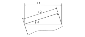
- the permanent magnets 22a and 22b included in the mover 2 are arranged to be inclined at an angle ⁇ .
- the permanent magnets 22a and 22b are tilted so that the angle formed with respect to the direction intersecting the moving direction of the mover 2 (vertical direction in FIG. 5) is an angle ⁇ . That is, the skew is arranged at an angle ⁇ .
- the width of the permanent magnets 22a and 22b is L0.
- the length in the moving direction of the permanent magnets 22a and 22b is L1.
- FIG. 6 is a side view of the linear motor 100.
- FIG. 6 also shows a stator 1 having a minimum configuration of 7 poles and 6 slots. Relationship between the above-mentioned Pt and P M, if it does not consider the skew of the permanent magnet, i.e., the relationship in the case of ⁇ is 0 °.
- the pitch of the permanent magnet increases.
- the pitch between teeth is also changed.
- Pt1 Pt / cos ⁇ .
- the thickness of the auxiliary tooth part 13b is set to Wt.
- the mover 2 includes a total of seven permanent magnets 22a and 22b.
- the widths of the tooth portions 11b and 12b and the auxiliary tooth portion 13b are Wt.
- the pitch corresponding to the magnet skew of the tooth portions 11b and 12b and the auxiliary tooth portion 13b is Pt1.
- the total length Ls of the stator 1 is assumed.
- the total length Ls of the stator 1 is longer than the total length Lm of the magnet portion of the mover 2 by Pt1 + Wt or more.
- the U-phase, V-phase, and W-phase must be in reverse pairs. That is, it is increased in units of 6 slots. If it does so, it will become possible to increase a stroke, maintaining a motor characteristic.
- the 7-pole 6-slot configuration is shown here, the same applies to a 14-pole 12-slot configuration, a 3-pole 21-pole 18-slot configuration, and a 7-n pole 6n-slot configuration that is n-fold. is there. Even if n times, the difference between Ls and Lm is Pt1 + Wt.
- the linear motor 100 shown in FIG. 4 has a 14-pole 12-slot configuration that doubles the 7-pole 6-slot configuration.
- the number of slots of the stator 1 is increased by 6 slots to 18 slots.
- the overhang means that the tip of the mover 2 protrudes from the stator 1.
- the amount of overhang refers to the length in the moving direction of the permanent magnets 22a and 22b of the mover 2 that does not face the teeth 11b (12b) of the stator 1.
- FIG. 7A and 7B are explanatory diagrams of the overhang amount.
- FIG. 7A shows the overhang amount (d1) allowed when there is no auxiliary tooth portion 13b.
- FIG. 7B shows the overhang amount (d2) allowed when the auxiliary tooth portion 13b is provided.
- the permissible overhang amount refers to a range in which the thrust is obtained with substantially the same value as in a steady state.
- an allowable overhang amount is extended by the auxiliary tooth portion 13 b. This is because the provision of the auxiliary tooth portion 13b absorbs the magnetic flux due to the end effect and reduces the pull back force (force opposite to the thrust force), so that a drop in thrust does not occur.
- this embodiment has the following effects.
- FIG. 8 is an explanatory view showing another configuration of the stator 1 excluding the coil 14.
- FIG. 8 is a side view of the stator 1 as in FIG. 2B.
- the top tips (tips) in the height direction of the tooth portions 11b and 12b of the magnetic pole tooth parts 11 and 12 have a reverse taper shape that is thicker than the root portions of the substrate portions 11a and 12a.
- the auxiliary tooth portion 13b also has an inverted tip at the top end, similar to the tooth portion 11b and the tooth portion 12b. If the top tips in the height direction of the tooth portions 11b and 12b are formed in a reverse taper shape, the transmission efficiency of magnetic flux can be further improved.
- the substrate portions 11a, 12a, and 13a may be configured as a single plate, and the tooth portions 11b and 12b and the auxiliary tooth portion 13b may be fixed by screwing or welding. Further, the tooth portions 11b and 12b and the auxiliary tooth portion 13b may be formed by cutting out from a block-shaped member.
- the armature is the stator 1 and the field part is the mover 2.
- the armature may be the mover and the field part may be fixed.
Abstract
Description
Ls=Pt1×6+Pt1+Wt
Lm=Pt1×6
Ls-Lm=Pt1+Wt Summarize the above. The widths of the
Ls = Pt1 × 6 + Pt1 + Wt
Lm = Pt1 × 6
Ls−Lm = Pt1 + Wt
今回開示された実施の形態はすべての点で例示であって、制限的なものでは無いと考えられるべきである。本発明の範囲は、上記した意味では無く、特許請求の範囲によって示され、特許請求の範囲と均等の意味及び範囲内でのすべての変更が含まれることが意図される。 The technical features (components) described in each embodiment can be combined with each other, and new technical features can be formed by combining them.
The embodiments disclosed herein are illustrative in all respects and should not be considered as restrictive. The scope of the present invention is defined not by the above-mentioned meaning but by the scope of the claims, and is intended to include all modifications within the meaning and scope equivalent to the scope of the claims.
1 固定子
11 磁極歯パーツ
11a 基板部
11b 歯部
12 磁極歯パーツ
12a 基板部
12b 歯部
13 補助歯パーツ
13a 基板部
13b 補助歯部
14 コイル
2 可動子
21 バックヨーク
22a 永久磁石
22b 永久磁石 DESCRIPTION OF
Claims (11)
- 矩形板状の基板部と、
該基板部に並設してあるコイルを巻回した複数の磁極歯と、
該基板部の前記並設方向の端部に、前記磁極歯から間隔をおいて設けられ、コイルを巻回していない補助歯とを備える
ことを特徴とするリニアモータ用電機子。 A rectangular plate-shaped substrate portion;
A plurality of magnetic pole teeth wound with coils arranged in parallel on the substrate portion;
An armature for a linear motor, comprising: an auxiliary tooth that is provided at an end portion in the parallel arrangement direction of the substrate portion at a distance from the magnetic pole teeth and is not wound with a coil. - 前記補助歯及び該補助歯に隣接する前記磁極歯の間隔は、隣接する2つの前記磁極歯の間隔と略同一としてある
ことを特徴とする請求項1に記載のリニアモータ用電機子。 The armature for a linear motor according to claim 1, wherein an interval between the auxiliary teeth and the magnetic pole teeth adjacent to the auxiliary teeth is substantially the same as an interval between two adjacent magnetic pole teeth. - 前記補助歯は、前記磁極歯と略同一形状としてある
ことを特徴とする請求項1又は請求項2に記載のリニアモータ用電機子。 The armature for a linear motor according to claim 1, wherein the auxiliary teeth have substantially the same shape as the magnetic pole teeth. - 前記補助歯及び磁極歯は直方体状をなし、
前記補助歯及び該補助歯に隣接する前記磁極歯は並設方向に正対している
ことを特徴とする請求項1から請求項3のいずれか一項に記載のリニアモータ用電機子。 The auxiliary teeth and magnetic pole teeth have a rectangular parallelepiped shape,
The armature for a linear motor according to any one of claims 1 to 3, wherein the auxiliary teeth and the magnetic pole teeth adjacent to the auxiliary teeth face each other in the juxtaposition direction. - 前記補助歯及び磁極歯は、その先端部が根元部よりも大きく、
前記補助歯及び該補助歯に隣接する前記磁極歯は並設方向に正対している
ことを特徴とする請求項1から請求項3のいずれか一項に記載のリニアモータ用電機子。 The auxiliary teeth and magnetic pole teeth have their tip portions larger than the root portions,
The armature for a linear motor according to any one of claims 1 to 3, wherein the auxiliary teeth and the magnetic pole teeth adjacent to the auxiliary teeth face each other in the juxtaposition direction. - 前記補助歯及び前記磁極歯それぞれの先端面は面一としてある
ことを特徴とする請求項4又は請求項5に記載のリニアモータ用電機子。 The armature for a linear motor according to claim 4 or 5, wherein tip surfaces of the auxiliary teeth and the magnetic pole teeth are flush with each other. - 前記並設方向の両端部それぞれに、前記補助歯を備える
ことを特徴とする請求項1から請求項6のいずれか一項に記載のリニアモータ用電機子。 The armature for a linear motor according to any one of claims 1 to 6, wherein the auxiliary teeth are provided at both ends in the juxtaposed direction. - 請求項1から請求項7のいずれか一項に記載のリニアモータ用電機子と、
該リニアモータ用電機子に先端面が対向する複数の磁石、及び該複数の磁石を磁極が交互に形成されるように直線上に配列してある矩形板状のバックヨークを有する界磁部とを備える
ことを特徴とするリニアモータ。 An armature for a linear motor according to any one of claims 1 to 7,
A plurality of magnets whose front end faces the linear motor armature, and a field portion having a rectangular plate-shaped back yoke in which the plurality of magnets are arranged in a straight line so that magnetic poles are alternately formed; A linear motor comprising: - 請求項8に記載のリニアモータにおいて、前記リニアモータ用電機子を固定子とし、前記界磁部を可動子とする
ことを特徴とするリニアモータ。 The linear motor according to claim 8, wherein the armature for the linear motor is a stator and the field portion is a mover. - 前記界磁部は7n個の磁石を有し、前記電機子が有する6n個(nは自然数)の前記磁極歯が前記7n個の磁石に対向する7n極6nスロット構成であり、
前記界磁部の移動方向に沿う前記電機子の長さが、前記7n個の磁石の長さよりも長い
ことを特徴とする請求項9に記載のリニアモータ。 The field portion has 7n magnets, and 6n (n is a natural number) of the armature of the armature has a 7n pole 6n slot configuration facing the 7n magnets,
The linear motor according to claim 9, wherein a length of the armature along a moving direction of the field magnet part is longer than a length of the 7n magnets. - 前記磁極歯及び補助歯のピッチをPt1、前記移動方向に沿う前記磁極歯及び補助歯の長さをWt、前記7n個の磁石のスキュー角度をθとした場合において、
前記移動方向に沿う前記電機子の長さが、前記7n個の磁石の長さよりもPt1+Wt以上長い
ことを特徴とする請求項10に記載のリニアモータ。
但し、Pt1=Pt/cosθ
Pt:磁石がスキューしていない(θ=0)場合の、磁極歯及び補助歯のピッチ When the pitch of the magnetic pole teeth and auxiliary teeth is Pt1, the length of the magnetic pole teeth and auxiliary teeth along the moving direction is Wt, and the skew angle of the 7n magnets is θ,
11. The linear motor according to claim 10, wherein the length of the armature along the moving direction is longer than the length of the 7n magnets by Pt1 + Wt or more.
However, Pt1 = Pt / cos θ
Pt: Pitch of magnetic pole teeth and auxiliary teeth when the magnet is not skewed (θ = 0)
Priority Applications (5)
| Application Number | Priority Date | Filing Date | Title |
|---|---|---|---|
| JP2017510071A JP6269895B2 (en) | 2015-03-31 | 2016-03-30 | Linear motor |
| CN201680020798.3A CN107534379B (en) | 2015-03-31 | 2016-03-30 | Linear motor |
| DE112016001548.8T DE112016001548T5 (en) | 2015-03-31 | 2016-03-30 | ANCHOR FOR A LINEAR ENGINE, AND LINEAR ENGINE USING THIS ANCHOR |
| KR1020177026621A KR101975692B1 (en) | 2015-03-31 | 2016-03-30 | Linear motor |
| US15/560,431 US10700585B2 (en) | 2015-03-31 | 2016-03-30 | Linear motor |
Applications Claiming Priority (2)
| Application Number | Priority Date | Filing Date | Title |
|---|---|---|---|
| JP2015072491 | 2015-03-31 | ||
| JP2015-072491 | 2015-03-31 |
Publications (1)
| Publication Number | Publication Date |
|---|---|
| WO2016159034A1 true WO2016159034A1 (en) | 2016-10-06 |
Family
ID=57004363
Family Applications (1)
| Application Number | Title | Priority Date | Filing Date |
|---|---|---|---|
| PCT/JP2016/060288 WO2016159034A1 (en) | 2015-03-31 | 2016-03-30 | Linear motor armature and linear motor |
Country Status (7)
| Country | Link |
|---|---|
| US (1) | US10700585B2 (en) |
| JP (1) | JP6269895B2 (en) |
| KR (1) | KR101975692B1 (en) |
| CN (1) | CN107534379B (en) |
| DE (1) | DE112016001548T5 (en) |
| TW (1) | TWI612753B (en) |
| WO (1) | WO2016159034A1 (en) |
Cited By (3)
| Publication number | Priority date | Publication date | Assignee | Title |
|---|---|---|---|---|
| CN107659109A (en) * | 2017-10-11 | 2018-02-02 | 常州汉姆电机有限公司 | Linear stepping motor |
| KR20190112153A (en) | 2017-03-24 | 2019-10-02 | 히타치 긴조쿠 가부시키가이샤 | Linear motor |
| US11377325B2 (en) * | 2013-12-05 | 2022-07-05 | Otis Elevator Company | Linear propulsion system |
Families Citing this family (8)
| Publication number | Priority date | Publication date | Assignee | Title |
|---|---|---|---|---|
| AU2018307363A1 (en) | 2017-07-27 | 2020-02-06 | Hyperloop Technologies, Inc. | Augmented permanent magnet system |
| WO2019126727A1 (en) | 2017-12-22 | 2019-06-27 | Mcdonald Harley C | Variable torque linear motor/generator/transmission |
| JP2020142912A (en) * | 2019-03-08 | 2020-09-10 | 株式会社日立ハイテク | Conveying device, specimen analysis system including the same, and specimen pretreatment device |
| DE102019108270A1 (en) * | 2019-03-29 | 2020-10-01 | Dormakaba Deutschland Gmbh | Sliding door system |
| KR20210054730A (en) | 2019-11-06 | 2021-05-14 | 주식회사 코베리 | Linear motor and transfer system using the same |
| CN111342634B (en) * | 2020-02-29 | 2021-09-24 | 中国科学院电工研究所 | Long armature linear motor with active control shielding coil |
| CN112737268A (en) * | 2020-12-30 | 2021-04-30 | 苏州博古特智造有限公司 | Linear motor |
| CN113054767B (en) * | 2021-03-05 | 2022-06-17 | 华中科技大学 | Stator permanent magnet type rotor core block type linear oscillation motor and unit group |
Citations (7)
| Publication number | Priority date | Publication date | Assignee | Title |
|---|---|---|---|---|
| JPS5568871A (en) * | 1978-11-17 | 1980-05-23 | Matsushita Electric Ind Co Ltd | Rectilinear-moving electric machine |
| JPH10257750A (en) * | 1997-03-14 | 1998-09-25 | Yaskawa Electric Corp | Linear motor |
| JP2005151753A (en) * | 2003-11-18 | 2005-06-09 | Canon Inc | Linear motor |
| DE102006013582A1 (en) * | 2006-03-22 | 2007-09-27 | Technische Universität Kaiserslautern | Synchronous linear motor for e.g. positioning object, has primary part with grooves for single or multi-phase windings, and secondary part with permanent magnets, where end pieces at primary part are provided for force ripple compensation |
| JP2009545940A (en) * | 2006-07-31 | 2009-12-24 | シーメンス アクチエンゲゼルシヤフト | Force ripple compensation linear motor |
| JP2011188709A (en) * | 2010-03-11 | 2011-09-22 | Yaskawa Electric Corp | Linear motor |
| WO2012176236A1 (en) * | 2011-06-22 | 2012-12-27 | 三菱電機株式会社 | Linear motor |
Family Cites Families (6)
| Publication number | Priority date | Publication date | Assignee | Title |
|---|---|---|---|---|
| JP2003189589A (en) | 2001-12-21 | 2003-07-04 | Canon Inc | Movable magnet type linear motor, exposure unit and method for manufacturing device |
| TWI244253B (en) * | 2003-11-21 | 2005-11-21 | Ind Tech Res Inst | Modular permanent-magnet synchronous linear motor |
| JP4860794B2 (en) | 2006-05-29 | 2012-01-25 | 三菱電機株式会社 | Linear motor |
| JP5106833B2 (en) | 2006-11-15 | 2012-12-26 | ヤマハ発動機株式会社 | Linear motor and single-axis actuator |
| TWM414027U (en) * | 2011-06-01 | 2011-10-11 | Hiwin Mikrosystem Corp | Linear motor Coil Package configuration |
| WO2014148434A1 (en) * | 2013-03-22 | 2014-09-25 | 日立金属株式会社 | Linear motor |
-
2016
- 2016-03-30 JP JP2017510071A patent/JP6269895B2/en active Active
- 2016-03-30 CN CN201680020798.3A patent/CN107534379B/en active Active
- 2016-03-30 US US15/560,431 patent/US10700585B2/en active Active
- 2016-03-30 KR KR1020177026621A patent/KR101975692B1/en active IP Right Grant
- 2016-03-30 DE DE112016001548.8T patent/DE112016001548T5/en active Pending
- 2016-03-30 TW TW105109989A patent/TWI612753B/en active
- 2016-03-30 WO PCT/JP2016/060288 patent/WO2016159034A1/en active Application Filing
Patent Citations (7)
| Publication number | Priority date | Publication date | Assignee | Title |
|---|---|---|---|---|
| JPS5568871A (en) * | 1978-11-17 | 1980-05-23 | Matsushita Electric Ind Co Ltd | Rectilinear-moving electric machine |
| JPH10257750A (en) * | 1997-03-14 | 1998-09-25 | Yaskawa Electric Corp | Linear motor |
| JP2005151753A (en) * | 2003-11-18 | 2005-06-09 | Canon Inc | Linear motor |
| DE102006013582A1 (en) * | 2006-03-22 | 2007-09-27 | Technische Universität Kaiserslautern | Synchronous linear motor for e.g. positioning object, has primary part with grooves for single or multi-phase windings, and secondary part with permanent magnets, where end pieces at primary part are provided for force ripple compensation |
| JP2009545940A (en) * | 2006-07-31 | 2009-12-24 | シーメンス アクチエンゲゼルシヤフト | Force ripple compensation linear motor |
| JP2011188709A (en) * | 2010-03-11 | 2011-09-22 | Yaskawa Electric Corp | Linear motor |
| WO2012176236A1 (en) * | 2011-06-22 | 2012-12-27 | 三菱電機株式会社 | Linear motor |
Cited By (3)
| Publication number | Priority date | Publication date | Assignee | Title |
|---|---|---|---|---|
| US11377325B2 (en) * | 2013-12-05 | 2022-07-05 | Otis Elevator Company | Linear propulsion system |
| KR20190112153A (en) | 2017-03-24 | 2019-10-02 | 히타치 긴조쿠 가부시키가이샤 | Linear motor |
| CN107659109A (en) * | 2017-10-11 | 2018-02-02 | 常州汉姆电机有限公司 | Linear stepping motor |
Also Published As
| Publication number | Publication date |
|---|---|
| CN107534379A (en) | 2018-01-02 |
| TW201707346A (en) | 2017-02-16 |
| KR101975692B1 (en) | 2019-05-07 |
| DE112016001548T5 (en) | 2018-01-04 |
| US10700585B2 (en) | 2020-06-30 |
| CN107534379B (en) | 2020-04-21 |
| JP6269895B2 (en) | 2018-02-07 |
| TWI612753B (en) | 2018-01-21 |
| US20180069464A1 (en) | 2018-03-08 |
| JPWO2016159034A1 (en) | 2017-10-19 |
| KR20170120150A (en) | 2017-10-30 |
Similar Documents
| Publication | Publication Date | Title |
|---|---|---|
| JP6269895B2 (en) | Linear motor | |
| JP5991326B2 (en) | Linear motor | |
| JP2010130871A (en) | Linear motor | |
| JP2007318839A (en) | Linear motor | |
| JP2010141978A (en) | Thrust generation mechanism | |
| JP5289799B2 (en) | Linear motor | |
| JP5987038B2 (en) | Linear motor that reduces cogging force | |
| JP6128206B2 (en) | Linear motor | |
| JP2013102695A (en) | Linear motor | |
| JP6596767B2 (en) | Linear motor field and linear motor | |
| JP5678025B2 (en) | Thrust generating mechanism | |
| JP6036221B2 (en) | Linear motor | |
| JP2018050430A (en) | Linear motor | |
| JP2006034016A (en) | Linear motor for machine tool | |
| JP2013176299A (en) | Linear motor | |
| JP6001828B2 (en) | Linear motor stator | |
| JP2007209175A (en) | Three-phase linear motor | |
| JP2006311687A (en) | Linear motor | |
| JP6197346B2 (en) | Linear motor | |
| JP2006136156A (en) | Linear motor | |
| JP2024006584A (en) | linear motor | |
| JP5489080B2 (en) | Linear motor and stage device | |
| JP2014204471A (en) | Linear motor | |
| JP2007209176A (en) | Three-phase linear motor | |
| JP2018137873A (en) | Linear motor |
Legal Events
| Date | Code | Title | Description |
|---|---|---|---|
| 121 | Ep: the epo has been informed by wipo that ep was designated in this application |
Ref document number: 16772915 Country of ref document: EP Kind code of ref document: A1 |
|
| DPE1 | Request for preliminary examination filed after expiration of 19th month from priority date (pct application filed from 20040101) | ||
| ENP | Entry into the national phase |
Ref document number: 2017510071 Country of ref document: JP Kind code of ref document: A |
|
| ENP | Entry into the national phase |
Ref document number: 20177026621 Country of ref document: KR Kind code of ref document: A |
|
| WWE | Wipo information: entry into national phase |
Ref document number: 15560431 Country of ref document: US |
|
| WWE | Wipo information: entry into national phase |
Ref document number: 112016001548 Country of ref document: DE |
|
| 122 | Ep: pct application non-entry in european phase |
Ref document number: 16772915 Country of ref document: EP Kind code of ref document: A1 |