WO2016159013A1 - 香味吸引器 - Google Patents
香味吸引器 Download PDFInfo
- Publication number
- WO2016159013A1 WO2016159013A1 PCT/JP2016/060251 JP2016060251W WO2016159013A1 WO 2016159013 A1 WO2016159013 A1 WO 2016159013A1 JP 2016060251 W JP2016060251 W JP 2016060251W WO 2016159013 A1 WO2016159013 A1 WO 2016159013A1
- Authority
- WO
- WIPO (PCT)
- Prior art keywords
- flow path
- housing
- flavor
- aerosol
- cartridge
- Prior art date
Links
Images


Classifications
-
- A—HUMAN NECESSITIES
- A24—TOBACCO; CIGARS; CIGARETTES; SIMULATED SMOKING DEVICES; SMOKERS' REQUISITES
- A24F—SMOKERS' REQUISITES; MATCH BOXES; SIMULATED SMOKING DEVICES
- A24F40/00—Electrically operated smoking devices; Component parts thereof; Manufacture thereof; Maintenance or testing thereof; Charging means specially adapted therefor
- A24F40/50—Control or monitoring
-
- A—HUMAN NECESSITIES
- A24—TOBACCO; CIGARS; CIGARETTES; SIMULATED SMOKING DEVICES; SMOKERS' REQUISITES
- A24F—SMOKERS' REQUISITES; MATCH BOXES; SIMULATED SMOKING DEVICES
- A24F42/00—Simulated smoking devices other than electrically operated; Component parts thereof; Manufacture or testing thereof
- A24F42/20—Devices without heating means
-
- A—HUMAN NECESSITIES
- A24—TOBACCO; CIGARS; CIGARETTES; SIMULATED SMOKING DEVICES; SMOKERS' REQUISITES
- A24F—SMOKERS' REQUISITES; MATCH BOXES; SIMULATED SMOKING DEVICES
- A24F40/00—Electrically operated smoking devices; Component parts thereof; Manufacture thereof; Maintenance or testing thereof; Charging means specially adapted therefor
- A24F40/40—Constructional details, e.g. connection of cartridges and battery parts
- A24F40/48—Fluid transfer means, e.g. pumps
- A24F40/485—Valves; Apertures
-
- A—HUMAN NECESSITIES
- A24—TOBACCO; CIGARS; CIGARETTES; SIMULATED SMOKING DEVICES; SMOKERS' REQUISITES
- A24F—SMOKERS' REQUISITES; MATCH BOXES; SIMULATED SMOKING DEVICES
- A24F40/00—Electrically operated smoking devices; Component parts thereof; Manufacture thereof; Maintenance or testing thereof; Charging means specially adapted therefor
- A24F40/40—Constructional details, e.g. connection of cartridges and battery parts
- A24F40/48—Fluid transfer means, e.g. pumps
-
- A—HUMAN NECESSITIES
- A24—TOBACCO; CIGARS; CIGARETTES; SIMULATED SMOKING DEVICES; SMOKERS' REQUISITES
- A24F—SMOKERS' REQUISITES; MATCH BOXES; SIMULATED SMOKING DEVICES
- A24F42/00—Simulated smoking devices other than electrically operated; Component parts thereof; Manufacture or testing thereof
- A24F42/10—Devices with chemical heating means
-
- A—HUMAN NECESSITIES
- A24—TOBACCO; CIGARS; CIGARETTES; SIMULATED SMOKING DEVICES; SMOKERS' REQUISITES
- A24F—SMOKERS' REQUISITES; MATCH BOXES; SIMULATED SMOKING DEVICES
- A24F42/00—Simulated smoking devices other than electrically operated; Component parts thereof; Manufacture or testing thereof
- A24F42/60—Constructional details
-
- A—HUMAN NECESSITIES
- A61—MEDICAL OR VETERINARY SCIENCE; HYGIENE
- A61M—DEVICES FOR INTRODUCING MEDIA INTO, OR ONTO, THE BODY; DEVICES FOR TRANSDUCING BODY MEDIA OR FOR TAKING MEDIA FROM THE BODY; DEVICES FOR PRODUCING OR ENDING SLEEP OR STUPOR
- A61M15/00—Inhalators
- A61M15/06—Inhaling appliances shaped like cigars, cigarettes or pipes
-
- A—HUMAN NECESSITIES
- A24—TOBACCO; CIGARS; CIGARETTES; SIMULATED SMOKING DEVICES; SMOKERS' REQUISITES
- A24F—SMOKERS' REQUISITES; MATCH BOXES; SIMULATED SMOKING DEVICES
- A24F40/00—Electrically operated smoking devices; Component parts thereof; Manufacture thereof; Maintenance or testing thereof; Charging means specially adapted therefor
- A24F40/10—Devices using liquid inhalable precursors
-
- A—HUMAN NECESSITIES
- A24—TOBACCO; CIGARS; CIGARETTES; SIMULATED SMOKING DEVICES; SMOKERS' REQUISITES
- A24F—SMOKERS' REQUISITES; MATCH BOXES; SIMULATED SMOKING DEVICES
- A24F40/00—Electrically operated smoking devices; Component parts thereof; Manufacture thereof; Maintenance or testing thereof; Charging means specially adapted therefor
- A24F40/30—Devices using two or more structurally separated inhalable precursors, e.g. using two liquid precursors in two cartridges
-
- A—HUMAN NECESSITIES
- A61—MEDICAL OR VETERINARY SCIENCE; HYGIENE
- A61M—DEVICES FOR INTRODUCING MEDIA INTO, OR ONTO, THE BODY; DEVICES FOR TRANSDUCING BODY MEDIA OR FOR TAKING MEDIA FROM THE BODY; DEVICES FOR PRODUCING OR ENDING SLEEP OR STUPOR
- A61M15/00—Inhalators
- A61M15/0001—Details of inhalators; Constructional features thereof
- A61M15/0021—Mouthpieces therefor
-
- A—HUMAN NECESSITIES
- A61—MEDICAL OR VETERINARY SCIENCE; HYGIENE
- A61M—DEVICES FOR INTRODUCING MEDIA INTO, OR ONTO, THE BODY; DEVICES FOR TRANSDUCING BODY MEDIA OR FOR TAKING MEDIA FROM THE BODY; DEVICES FOR PRODUCING OR ENDING SLEEP OR STUPOR
- A61M2205/00—General characteristics of the apparatus
- A61M2205/33—Controlling, regulating or measuring
- A61M2205/3331—Pressure; Flow
Definitions
- the present invention relates to a flavor inhaler having an atomizing section for atomizing an aerosol source.
- the flavor inhaler includes an air channel that is continuous from an inlet to an outlet, and an atomizing unit that is disposed in the air channel and atomizes an aerosol source (for example, Patent Documents 1 and 2).
- the first feature is a flavor inhaler, comprising a housing having an air flow path continuous from an inlet to an outlet, and an atomizing unit for atomizing the aerosol source without combustion of the aerosol source, At least a part of the air flow path is an aerosol flow path that is a flow path of the aerosol generated from the atomizing portion, and the overall ventilation resistance of the air flow path is 25 mmAq or less.
- the second feature is that, in the first feature, the atomization is performed when the user is performing the suction operation without supplying a power output to the atomization unit when the user is not performing the suction operation.
- the flavor inhaler includes a switch for supplying power output to the unit.
- a third feature is that, in the second feature, the flavor inhaler includes a sensor that outputs a response value that changes according to the suction operation of the user.
- the gist is that the switch operates based on a response value output from the sensor.
- a fourth feature is the third feature, wherein the housing is configured to be detachable from the first housing for housing the atomizing portion and the first housing, and to supply electric power to the atomizing portion.
- a second housing that houses a power supply to be stored, and the sensor is housed in the second housing and is provided closer to the first housing than the power supply.
- the fifth feature is summarized in that, in the fourth feature, the inlet is provided between the sensor and the atomization unit.
- a sixth feature is any one of the third feature to the fifth feature, wherein the housing is a first cavity provided on the same side as the inlet and the outlet from the sensor, and the inlet and the sensor from the sensor. It has a second cavity provided on the opposite side of the outlet, and the first cavity and the second cavity are partitioned so as not to communicate with each other in the housing.
- the seventh feature is compared with the response value to determine whether to operate the switch so as not to supply a power output to the atomizing unit in any of the third to sixth features.
- the gist of the end threshold to be performed is larger than a start threshold compared with the response value in order to determine whether to operate the switch so as to supply a power output to the atomizing unit.
- the flavor inhaler includes an operation interface operated by a user, and the switch operates based on an operation on the operation interface.
- the ninth feature is summarized in that, in any one of the first to eighth features, the ventilation resistance of the entire air flow path is 15 mmAq or less.
- the tenth feature is summarized as any one of the first to ninth features, wherein the entire air flow resistance of the air flow path is 2 mmAq or more and 8 mmAq or less.
- An eleventh feature is any one of the first feature to the tenth feature, wherein the air flow path includes a first air flow path that passes through the atomization section and a second air flow that does not pass through the atomization section.
- the inlet includes a first inlet that introduces air into the first air flow path, and a second inlet that introduces air into the second air flow path, and the outlet includes the first inlet A first outlet for deriving air from an air flow path; and a second outlet for deriving air from the second air flow path, wherein the second inlet is different from the first inlet, and the second inlet
- the gist is that it is configured to be able to communicate with the aerosol flow path on the first outlet side with respect to the atomizing section, or to communicate with the second outlet without communicating with the aerosol flow path.
- the twelfth feature is summarized in that, in the eleventh feature, the amount of air flowing in from the second inlet is 50% or more of the amount of air flowing out of the outlet.
- a thirteenth feature is the eleventh feature or the twelfth feature, wherein the housing is an aspirator housing that houses at least the atomizing portion, and a flavor source provided closer to the first outlet than the atomizing portion. And the suction housing has the second inlet configured to be able to communicate with the aerosol flow path on the first outlet side with respect to the atomizing portion, The gist of the cartridge housing is to form at least a part of the second air flow path.
- the cartridge housing is configured to be inserted into the suction unit housing along a predetermined direction, and the cartridge housing is disposed outside the suction unit housing.
- a first recessed portion formed on a side surface, wherein the first recessed portion is annularly continuous in a cross section orthogonal to the predetermined direction at a position corresponding to the second inlet in the predetermined direction;
- the gist is to constitute a part of the second air flow path.
- a fifteenth feature is the eleventh feature or the twelfth feature, wherein the housing is an aspirator housing that houses at least the atomizing portion, and a flavor source provided closer to the first outlet than the atomizing portion. And the aspirator housing has the second inlet that communicates with the second outlet without communicating with the aerosol flow path.
- the cartridge housing is configured to be inserted into the suction unit housing along a predetermined direction, and the cartridge housing is arranged outside the suction unit housing.
- a second recessed portion formed on a side surface, wherein the second recessed portion is annularly continuous in a cross section perpendicular to the predetermined direction at a position corresponding to the second inlet in the predetermined direction.
- a seventeenth feature is the eleventh feature or the twelfth feature, wherein the housing is an aspirator housing that houses at least the atomizing portion, and a flavor source provided closer to the first outlet than the atomizing portion.
- the second inlet is formed on the cartridge protruding portion when the cartridge housing includes a cartridge protruding portion extending toward the first outlet side with respect to the suction device housing in the predetermined direction.
- the aspirator housing has an aspirator projecting portion extending toward the first outlet side of the cartridge housing in the predetermined direction, the aspirator housing is provided at the aspirator projecting portion.
- a flavor inhaler includes a flavor source provided on the first outlet side of the atomizing unit, and the second inlet includes the The gist is to be provided on the second outlet side from the flavor source.
- a flavor inhaler includes a flavor source provided on the outlet side of the atomizing unit, and the aerosol flow path includes the flavor source.
- a first aerosol flow path that guides the aerosol to the outlet side through the second aerosol flow path different from the first aerosol flow path, and the aerosol reduction rate in the second aerosol flow path is The gist is that it is smaller than the reduction rate of aerosol in one aerosol flow path.
- a twentieth feature is summarized in that, in the nineteenth feature, the second aerosol flow path is a flow path that guides the aerosol to the outlet side without passing through the flavor source.
- a flavor inhaler in any one of the first to twentieth features, includes a flavor source unit having a flavor source provided on the outlet side of the atomizing portion, and the housing includes:
- the flavor source unit has a shape extending along a predetermined direction, and the flavor source unit is disposed in the housing so as to divide the aerosol flow path into a first space on the inlet side and a second space on the outlet side.
- the area of the flavor source unit exposed in at least one of the first space and the second space is larger than the cross-sectional area defined by the inner periphery of the housing in a cross section orthogonal to the predetermined direction. The main point is that it is large.
- the flavor source unit divides the first space and the second space along the predetermined direction, and the flavor source unit includes the first space and the second space.
- the first wall body exposed to the second space and the second wall body continuous with the first wall body, the first wall body is constituted by a member having air permeability,
- the gist is that the area of the outer surface of the first wall body is larger than the area of the outer surface of the second wall body.
- a twenty-third feature is that, in any one of the first to twenty-second features, the flavor suction device is configured such that the overall ventilation resistance of the air flow path is variable to 25 mmAq or less.
- the distance between the inlet and the sensor may be 20 mm or less.
- the distance between the inlet and the sensor is preferably 15 mm or less, and more preferably 10 mm or less.
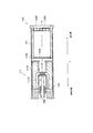
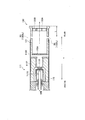
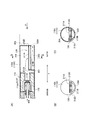
- FIG. 1 is a view showing a non-burning type flavor inhaler 100 according to the first embodiment.
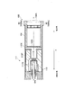
- FIG. 2 is a diagram illustrating the atomization unit 111 according to the first embodiment.
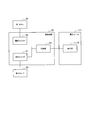
- FIG. 3 is a diagram illustrating a block configuration of the non-burning type flavor inhaler 100 according to the first embodiment.
- FIG. 4 is a diagram illustrating the atomization unit 111 and the cartridge 130 according to the first modification.
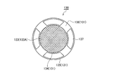
- FIG. 5 is a diagram illustrating the atomization unit 111 and the cartridge 130 according to the second modification.
- FIG. 6 is a diagram illustrating the atomization unit 111 and the cartridge 130 according to the second modification.
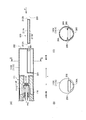
- FIG. 7 is a view showing the atomization unit 111 and the cartridge 130 according to the third modification.
- FIG. 8 is a diagram illustrating the atomization unit 111 and the cartridge 130 according to the third modification.
- FIG. 9 is a diagram illustrating the atomization unit 111 and the cartridge 130 according to the third modification.
- FIG. 10 is a diagram illustrating the atomization unit 111 and the cartridge 130 according to the fourth modification.
- FIG. 11 is a diagram illustrating an atomization unit 111 and a cartridge 130 according to Modification 6.
- FIG. 12 is a view showing an atomization unit 111 and a cartridge 130 according to Modification 7.
- FIG. 13 is a diagram illustrating a sensor 20 according to the eighth modification.
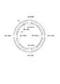
- FIG. 14 is a view showing a cartridge 130 according to Modification 9.
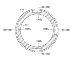
- FIG. 15 is a view showing a cartridge 130 according to Modification 9.
- FIG. 16 is a diagram illustrating an atomization unit 111 and a cartridge 130 according to Modification 9.
- FIG. 17 is a diagram illustrating the atomization unit 111 and the cartridge 130 according to the tenth modification.
- FIG. 18 is a diagram illustrating the atomization unit 111 and the cartridge 130 according to the tenth modification.
- FIG. 19 is a diagram for explaining the experimental results.
- FIG. 20 is a diagram for explaining the experimental results.
- FIG. 21 is a diagram for explaining the experimental results.
- FIG. 22 is a diagram for explaining the experimental results.
- a flavor inhaler includes a housing having an air flow path that is continuous from an inlet to an outlet, and an atomization unit that atomizes the aerosol source without combustion of the aerosol source. At least a part is an aerosol flow path, which is an aerosol flow path generated from the atomization section, and the entire air flow resistance of the air flow path is 25 mmAq or less.
- the ventilation resistance of the entire air flow path is 25 mmAq or less, it is difficult for the user to perform puff suction for retaining the aerosol in the oral cavity, and direct suction operation (hereinafter, direct suction) is easily performed. . Therefore, a reduction in the flavor can be suppressed by reducing the loss of the aerosol.
- FIG. 1 is a view showing a non-burning type flavor inhaler 100 according to the first embodiment.
- the non-burning type flavor inhaler 100 is a device for sucking flavor components and has a shape extending along a predetermined direction A that is a direction from the non-suction end toward the suction end.
- FIG. 2 is a diagram illustrating the atomization unit 111 according to the first embodiment.
- the non-burning type flavor inhaler 100 is simply referred to as the flavor inhaler 100.
- the flavor suction device 100 includes a suction device main body 110 and a cartridge 130.
- the suction unit main body 110 constitutes the main body of the flavor suction unit 100 and has a shape to which the cartridge 130 can be connected. Specifically, the suction unit main body 110 has a suction unit housing 110X, and the cartridge 130 is connected to the suction side end of the suction unit housing 110X.
- the inhaler main body 110 includes an atomization unit 111 configured to atomize the aerosol source without burning the aerosol source, and an electrical unit 112. The atomization unit 111 and the electrical unit 112 are accommodated in the aspirator housing 110X.
- the atomization unit 111 includes a first cylinder 111X (that is, a first housing) that constitutes a part of the suction device housing 110X.
- the atomization unit 111 includes a reservoir 111P, a wick 111Q, and an atomization unit 111R.
- the reservoir 111P, the wick 111Q, and the atomization unit 111R are accommodated in the first cylinder 111X.
- the first cylinder 111X has a cylindrical shape (for example, a cylindrical shape) extending along the predetermined direction A.
- the reservoir 111P holds an aerosol source.
- the reservoir 111P is a porous body made of a material such as a resin web.
- the wick 111Q is an example of an aerosol suction unit that sucks up an aerosol source held in the reservoir 111P.
- the wick 111Q is made of glass fiber.
- the atomization unit 111R atomizes the aerosol source sucked up by the wick 111Q.
- the atomization part 111R is comprised by the heating resistor (for example, heating wire) wound around the wick 111Q at a predetermined pitch, for example.
- the aerosol source is a liquid such as glycerin or propylene glycol.
- the aerosol source is held by a porous body made of a material such as a resin web.
- the porous body may be made of a non-tobacco material or may be made of a tobacco material.
- the aerosol source may include a flavor source containing a nicotine component or the like.
- the aerosol source may not include a flavor source containing a nicotine component or the like.
- the aerosol source may include a flavor source containing components other than the nicotine component.
- the aerosol source may not include a flavor source that includes components other than the nicotine component.
- the atomizing unit 111 a heating type unit that atomizes an aerosol source by heating is illustrated.
- the atomization unit 111 only needs to have a function of atomizing the aerosol source, and may be an ultrasonic type unit that atomizes the aerosol source using ultrasonic waves.
- the electrical unit 112 has a second cylinder 112X (that is, a second housing) that constitutes a part of the suction unit housing 110X.
- the electrical unit 112 has an inlet 112A.
- the air flowing from the inlet 112A is guided to the atomization unit 111 (the atomization unit 111R).
- the electrical unit 112 includes a power supply 10, a sensor 20, a push button 30, and a control circuit 50.
- the power supply 10, the sensor 20, the push button 30, and the control circuit 50 are accommodated in the second cylinder 112X.
- the second cylinder 112X has a cylindrical shape (for example, a cylindrical shape) extending along the predetermined direction A.
- the power source 10 is, for example, a lithium ion battery.
- the power supply 10 stores electric power necessary for the operation of the flavor inhaler 100.
- the power supply 10 stores electric power supplied to the sensor 20 and the control circuit 50.
- the power supply 10 accumulate
- Sensor 20 is a sensor (a suction sensor, a flow sensor, a pressure sensor, etc.) for detecting a user's suction operation.
- the sensor 20 outputs a response value that varies depending on the air sucked from the non-suction end toward the suction end (that is, the user's suction operation).
- the push button 30 is configured to be pushed inward from the outside of the flavor inhaler 100.
- the push button 30 is provided at the non-suction end of the flavor suction device 100 and is configured to be pushed in a direction from the non-suction end toward the suction end (that is, the predetermined direction A). For example, when the push button 30 is continuously pressed a predetermined number of times, the flavor inhaler 100 is turned on. Note that the power source of the flavor inhaler 100 is disconnected when a predetermined time has elapsed since the suction operation was performed.
- the control circuit 50 controls the operation of the flavor inhaler 100. Specifically, the control circuit 50 controls the power output for the atomization unit 111 (the atomization unit 111R).
- the cartridge 130 is configured to be connectable to the aspirator body 110 constituting the flavor inhaler 100.
- the cartridge 130 is located closer to the outlet (suction port) side than the atomization unit 111 on the air flow path that extends from the inlet (the inlet 112A described above in the first embodiment) to the outlet (the outlet 130A described below in the first embodiment).
- the cartridge 130 is not necessarily provided on the outlet (suction port) side of the atomization unit 111 in physical space, and is provided on the outlet (suction port) side of the atomization unit 111 on the air flow path. It only has to be.
- the “outlet (suction port side)” may be considered to be synonymous with “downstream” of the air flow in the suction operation, and the “non-suction side” is the air flow in the suction operation. It may be considered synonymous with “upstream”.
- the cartridge 130 includes a cartridge housing 131, a flavor source 132, a mesh 133A, and a filter 133B. Further, the cartridge 130 has an outlet 130A provided at the suction port.
- the cartridge housing 131 has a cylindrical shape (for example, a cylindrical shape) extending along the predetermined direction A.
- the cartridge housing 131 accommodates the flavor source 132.
- the cartridge housing 131 is configured to be inserted along the predetermined direction A into the aspirator housing 110X.
- the flavor source 132 is provided on the outlet 130A (suction port) side of the atomization unit 111 on the continuous air flow path from the inlet 112A to the outlet 130A.
- the flavor source 132 imparts a flavor component to the aerosol generated from the aerosol source. In other words, the flavor component imparted to the aerosol by the flavor source 132 is carried to the outlet 130A (sucking mouth).
- the flavor source 132 is constituted by a raw material piece that imparts a flavor component to the aerosol generated from the atomization unit 111.
- the size of the raw material piece is preferably 0.2 mm or more and 1.2 mm or less. Furthermore, the size of the raw material pieces is preferably 0.2 mm or more and 0.7 mm or less. Since the specific surface area increases as the size of the raw material piece constituting the flavor source 132 is smaller, the flavor component is easily released from the raw material piece constituting the flavor source 132. Therefore, the amount of the raw material pieces can be suppressed when applying the desired amount of flavor component to the aerosol.
- molded the cut tobacco and the tobacco raw material in the granule can be used as a raw material piece which comprises the flavor source 132.
- the flavor source 132 may be a molded body obtained by molding a tobacco material into a sheet shape.
- the raw material piece which comprises the flavor source 132 may be comprised by plants (for example, mint, an herb, etc.) other than tobacco.
- the flavor source 132 may be provided with a fragrance such as menthol.
- the raw material piece constituting the flavor source 132 is obtained, for example, by sieving in accordance with JIS Z 8815 using a stainless steel sieve in accordance with JIS Z 8801.
- a stainless steel sieve having an opening of 0.71 mm the raw material pieces are screened for 20 minutes by a dry and mechanical shaking method, and then passed through a stainless steel sieve having an opening of 0.71 mm. Get raw material pieces.
- a stainless steel sieve having an opening of 0.212 mm the raw material pieces are sieved for 20 minutes by a dry and mechanical shaking method, and then passed through a stainless steel sieve having an opening of 0.212 mm. Remove raw material pieces.
- the flavor source 132 is a tobacco source having an alkaline pH.
- the pH of the tobacco source is preferably greater than 7, more preferably 8 or more. By making the pH higher than 7, the flavor components generated from the tobacco source can be efficiently taken out by aerosol. Thereby, in providing a desired amount of flavor components to the aerosol, the amount of tobacco source can be suppressed.
- the pH of the tobacco source is preferably 14 or less, and more preferably 10 or less. By setting the pH to 14 or less, damage (corrosion or the like) to the flavor suction device 100 (for example, the cartridge 130 or the suction device main body 110) can be more effectively suppressed.
- flavor component generated from the flavor source 132 is conveyed by aerosol, and it is not necessary to heat the flavor source 132 itself.
- the mesh 133A is provided so as to close the opening of the cartridge housing 131 on the non-suction side with respect to the flavor source 132, and the filter 133B closes the opening of the cartridge housing 131 on the suction side with respect to the flavor source 132.
- the mesh 133A has such a roughness that the raw material pieces constituting the flavor source 132 do not pass therethrough.
- the roughness of the mesh 133A has, for example, a mesh opening of 0.077 mm or more and 0.198 mm or less.
- the filter 133B is made of a material having air permeability.
- the filter 133B is preferably an acetate filter, for example.
- the filter 133B has such a roughness that the raw material pieces constituting the flavor source 132 do not pass through.
- the aspirator housing 110X and the cartridge housing 131 of the aspirator body 110 constitute a housing having an air flow path continuous from the inlet 112A to the outlet 130A. At least a part of the air flow path (that is, the flow path on the downstream side of the atomization unit 111R shown in FIG. 2) is an aerosol flow path that is a flow path of the aerosol generated from the atomization unit 111.
- the ventilation resistance of the entire air flow path is 25 mmAq or less.
- the entire ventilation resistance of the air flow path is 15 mmAq or less. More preferably, the ventilation resistance of the whole air flow path is 2 mmAq or more and 8 mmAq or less.
- the smaller the ventilation resistance the less likely the user will perform the puff suction that retains the aerosol in the oral cavity, and the easier the direct suction operation (direct suction) will be. It should be noted that 1 mmAq corresponds to 9.80665 Pa.
- the ventilation resistance is measured by a method based on ISO 6565-1997 Draw resistance of cigarettes and pressure drop of filter rods.
- the ventilation resistance is the pressure when the devices are connected in the order of the flavor suction device 100, the differential pressure gauge, the mass flow controller, and the vacuum pump from the upstream side of the air flow path, and the vacuum pump sucks at 1050 ml / min. Defined as loss.
- the ventilation resistance of the whole air flow path is 0.5 mmAq or more. Furthermore, it is preferable that the ventilation resistance of the whole air flow path is not less than a value at which the above-described sensor 20 can detect the suction operation.
- FIG. 3 is a diagram illustrating a block configuration of the flavor inhaler 100 according to the first embodiment.
- control circuit 50 includes a suction switch 51, a power switch 52, and a control unit 53.
- the suction switch 51 is a switch that switches to an on state when the user is performing a suction operation, and switches to an off state when the user is not performing a suction operation.
- the suction switch 51 is connected to a sensor 20 for detecting a user's suction operation, and operates based on a response value output from the sensor 20. That is, the suction switch 51 is turned on when the response value indicates that a suction operation is being performed. On the other hand, the suction switch 51 is switched to an off state when the response value indicates that the suction operation is not performed.
- the power switch 52 is turned on when the power of the non-burning type flavor inhaler 100 is turned on, and is turned off when the power of the non-burning type flavor inhaler 100 is turned off.
- the power switch 52 is connected to the push button 30 and is turned on when the push button 30 is continuously pushed in a predetermined number of times.
- the power switch 52 has a timer and switches to an off state when a predetermined time has elapsed since the suction operation was performed.
- the control unit 53 controls the non-combustion type flavor inhaler 100 in a state where the power of the non-combustion type flavor inhaler 100 is turned on. Specifically, the control unit 53 controls the power output to the atomization unit 111R. The control unit 53 supplies a power output to the atomizing unit 111R when the user is performing a suction operation, that is, when the suction switch 51 is in an on state. On the other hand, the control unit 53 does not supply the power output to the atomizing unit 111R when the user is not performing the suction operation, that is, when the suction switch 51 is in the off state.
- the suction switch 51 does not supply power to the atomizing unit 111R when the user is not performing a suction operation, and power is supplied to the atomizing unit 111R when the user is performing a suction operation.
- the magnitude of the power output is defined by the value of the voltage applied to the atomizing unit 111R in the case where a voltage is continuously applied to the atomizing unit 111R.
- the magnitude of the power output is the value of the voltage applied to the atomizing unit 111R, the pulse width, and the like. It is defined by at least one parameter of the pulse interval.
- the end threshold is larger than the start threshold.
- the end threshold value is a threshold value that is compared with a response value output from the sensor 20 in order to determine whether to operate the suction switch 51 so as not to supply power output to the atomizing unit 111R, that is, the suction switch 51 This is a threshold that is compared with the response value to determine whether to turn it off.
- the start threshold value is a threshold value that is compared with a response value output from the sensor 20 in order to determine whether to operate the suction switch 51 to supply power output to the atomizing unit 111R, that is, suction. The threshold value is compared with the response value to determine whether to turn on the switch 51.
- the end threshold value is larger than the start threshold value, the actual suction operation continues even after the supply of power output to the atomizing unit 111R is stopped. Retention and condensation are suppressed, and aerosol loss is suppressed.
- the start threshold value is smaller than the end threshold value, supply of power output to the atomizing unit 111R is started promptly after the actual suction operation is started.
- the air flow path includes a first air flow path that passes through the atomization section 111R and a second air flow path that does not pass through the atomization section 111R.
- the inlet includes an inlet 112A (first inlet) for introducing air into the first air flow path, and an inlet 80 (second inlet) for introducing air into the second air flow path.
- the outlet includes an outlet 130A (first outlet) for deriving air from the first air flow path and an outlet 130A (second outlet) for deriving air from the second air flow path.
- the inlet 80 (second inlet) is different from the inlet 112A (first inlet).
- the aerosol flow path is a part of the first air flow path.
- the cartridge housing 131 is configured to be inserted along the predetermined direction A into the aspirator housing 110X.
- the suction unit housing 110 ⁇ / b> X has a suction unit through-hole 110 ⁇ / b> B that penetrates the suction unit housing 110 ⁇ / b> X in a direction that intersects the predetermined direction A, and the cartridge housing 131 intersects the predetermined direction A.
- a cartridge through hole 130B that penetrates the cartridge housing 131 in the direction is provided.
- the suction device through hole 110 ⁇ / b> B and the cartridge through hole 130 ⁇ / b> B constitute an inlet 80 (second inlet) and communicate with the inner space of the cartridge housing 131.
- the aspirator through-hole 110B is configured to be able to communicate with the aerosol channel on the outlet 130A side from the atomizing portion 111R.
- “communicable” means that the suction device through-hole 110B communicates with the air flow path by correctly inserting the cartridge housing 131 into the suction device housing 110X. Therefore, it should be noted that depending on the mode in which the cartridge housing 131 is inserted into the suction unit housing 110X, the suction unit through hole 110B may not communicate with the air flow path. However, it should be noted that “communicable” includes a mode in which the suction device through hole 110B always communicates with the air flow path, as described in Modifications 2 and 3 described later.
- the inlet 80 is provided separately from the inlet 112A.
- the inlet 80 is preferably located on the inlet side with respect to the atomizing portion 111R in the sense of spatial arrangement not related to upstream / downstream of the air flow path.
- the outlet 130A constitutes both a first outlet for deriving air from the first air flow path and a second outlet for deriving air from the second air flow path.
- the second air flow path is configured by the inlet 80 (aspirator through hole 110B and cartridge through hole 130B), a part of the aerosol flow path (the inner space of the cartridge housing 131), and the outlet 130A. .
- the cartridge through-hole 130 ⁇ / b> B is configured by one or more holes having a size that does not allow the raw material pieces constituting the flavor source 132 to pass.
- the cartridge through-hole 130 ⁇ / b> B has a mesh having such a roughness that the raw material pieces constituting the flavor source 132 do not pass through.
- the size to the extent that the raw material piece does not pass is, for example, 0.077 mm to 0.198 mm, and the roughness to the extent that the raw material piece does not pass is, for example, an opening of 0.077 mm to 0.198 mm.
- the amount of air flowing in from the inlet 80 (the suction device through hole 110B and the cartridge through hole 130B) is 50% or more of the amount of air flowing out from the outlet 130A.
- the amount of air flowing from the suction device through hole 110B is equal to or larger than the amount of air flowing from the inlet 112A.
- the amount of air flowing in from the inlet 80 is 60% or more of the amount of air flowing out from the outlet 130A.
- the distance L between the inlet end (here, the inlet end of the cartridge housing 131) of the housing having the air flow path in the predetermined direction A and the inlet 80 (second inlet) is 1.5 mm or more. It is preferable that Further, the distance L is preferably 3.0 mm or more, and more preferably 5.0 mm or more. Most preferably, the distance L is 8.0 mm or more.
- the distance L is preferably smaller than the distance between the inlet end of the housing having the air flow path in the predetermined direction A (here, the inlet end of the cartridge housing 131) and the inlet 112A (first inlet).
- the distance L may be smaller than the total length of the cartridge 130 in the predetermined direction.
- the total length of the cartridge 130 is preferably 5 mm or greater and 30 mm or less, and more preferably 10 mm or greater and 25 mm or less.
- the distance L is preferably less than 25 mm on the assumption that it is smaller than the total length of the cartridge 130.
- the distance L is preferably less than 20 mm, and more preferably less than 15 mm. Most preferably, the distance L is less than 10 mm. This makes it easy to suppress the overall ventilation resistance of the air flow path to 25 mmAq or less.
- the number of suction device through holes 110B provided in the housing may be one, or two or more. That is, the number of suction device through holes 110B is not particularly limited.
- the non-combustion flavor inhaler 100 has a second air flow path that does not pass through the atomization section 111R in addition to the first air flow path that passes through the atomization section 111R. Therefore, even when the air flowing in from the inlet 112A passes through the atomizing portion 111R, the overall ventilation resistance of the air flow path can be easily suppressed to 25 mmAq or less.
- the amount of air flowing from the inlet 80 is 50% or more of the amount of air flowing out from the outlet 130A. Therefore, even when the air flowing in from the inlet 112A passes through the atomizing portion 111R, the overall ventilation resistance of the air flow path can be easily suppressed to 25 mmAq or less.
- the inlet 80 includes the suction device through hole 110B and the cartridge through hole 130B.
- the inlet 80 includes a suction device through hole 110 ⁇ / b > B, a cartridge recessed portion 130 ⁇ / b > B 1, and a cartridge through hole 130 ⁇ / b > B 2 .
- Cartridge recessed portion 130B 1 is provided so as to surround the entire periphery of the cartridge housing 131 in a cross section perpendicular to a given direction A.
- Cartridge through hole 130B 2 is provided in the cartridge recessed portion 130B 1.
- FIG. 6 shows an FF cross section (that is, a cross section orthogonal to the predetermined direction A) shown in FIG.
- the cartridge housing 131 is configured to be inserted along the predetermined direction A into the aspirator housing 110X.
- the cartridge housing 131 includes a cartridge recess portion 130 ⁇ / b> B 1 (first recess portion) formed on the outer surface adjacent to the suction unit housing 110 ⁇ / b> X and a cartridge in a direction crossing the predetermined direction A.
- a cartridge through hole 130B 2 penetrating through the recessed portion 130B 1 .
- the cartridge recess portion 130B 1 (first recess portion) is annularly continuous in a cross section orthogonal to the predetermined direction A at a position where the suction device through hole 110B is provided in the predetermined direction A.
- annularly continuous does not have to be continuous over the entire circumferential direction (360 °) centering on the predetermined direction A in a cross section orthogonal to the predetermined direction A.
- the cartridge recessed portion 130B 1 may be partitioned by the discontinuous portions in the circumferential direction.
- each of the width of the portion 130B 1 recessed cartridge partitioned by discontinuous portion may be greater than the spacing of the sucker through holes 110B which are adjacent to each other (the closest distance).
- variety of the suction device through-hole 110B should just be larger than the width
- the second air flow path includes the inlet 80 (aspirator through-hole 110B, cartridge recessed portion 130B 1 , cartridge through-hole 130B 2 ), part of the aerosol flow path (the inner space of the cartridge housing 131). And an outlet 130A.
- the cartridge recess portion 130B 1 is constituted by reducing the thickness of the cartridge housing 131.
- the modified example 2 is not limited to this.
- Cartridge recessed portion 130B 1 only needs to be configured to allow a gap between the outer surface of the inner surface of the suction housing 110X and the cartridge housing 131.
- a thickness of the cartridge housing 131 is constant, the cartridge housing 131 has a recessed portion recessed inward in a cross section perpendicular to the predetermined direction A, even such recessed portion is a portion 130B 1 recessed cartridge Good.
- the inlet 80 includes a cartridge recessed portion 130B 1 is annularly continuous in the cross section perpendicular to the predetermined direction A. Therefore, in addition to the same effects as in the first modification, even if the cartridge housing 131 is inserted into the aspirator housing 110X without worrying about the relative position between the cartridge housing 131 and the aspirator housing 110X in the rotation direction of the cartridge housing 131. since the aspirator through hole 110B is 1 and communicates cartridge recessed portion 130B, it is possible to always form a second air flow path.
- the second air flow path includes a part of the aerosol flow path (the inner space of the cartridge housing 131).
- the suction device through hole 110 ⁇ / b> B and the cartridge through hole 130 ⁇ / b> B constitute the inlet 80 (second inlet) and communicate with the inner space of the cartridge housing 131.
- the second air flow path does not include a part of the aerosol flow path (the inner space of the cartridge housing 131).
- the aspirator through hole 110B constitutes the inlet 80 (second inlet) and communicates with the outlet 130A 1 (second outlet) without communicating with the aerosol flow path.
- the inlet 80 is provided separately from the inlet 112A.
- the inlet 80 is preferably located on the inlet side with respect to the atomizing portion 111R in the sense of spatial arrangement not related to upstream / downstream of the air flow path.
- the outlet 130A constitutes a first outlet for deriving air from the first air flow path, and the outlet 130A 1 is provided separately from the outlet 130A, and a second for deriving air from the second air flow path. Configure outlets. Outlet 130A 1 and the outlet 130A is provided on the suction port.
- the cartridge housing 131 is configured to be inserted along the predetermined direction A into the aspirator housing 110X. As shown in FIG. 7, the cartridge housing 131 forms at least a part of the second air flow path that does not have a flow path common to the aerosol flow path.
- the cartridge housing 131 has a cartridge recess portion 130B 3 (second recess portion) formed on the outer surface adjacent to the suction device housing 110X.
- the cartridge recess portion 130B 3 is preferably continuous along the predetermined direction A from the suction device through hole 110B (second inlet) to the outlet 130A 1 (second outlet).
- Cartridge recessed portion 130B 3 constitutes a part of the second air passage.
- portions 130B 3 cartridge recess may be provided at positions corresponding to the suction device through hole 110B.
- portions 130B 3 cartridge recess may be provided at positions corresponding to the suction device through hole 110B.
- FIG. 8 four suction device through holes 110B are illustrated, and four cartridge recessed portions 130B 3 are provided at positions corresponding to these suction device through holes 110B.
- the overall length of the cartridge recessed portion 130B 3 is preferably longer than the width of the aspirator through hole 110B. 8 shows the HH cross section (cross section orthogonal to the predetermined direction A) shown in FIG.
- portion 130B 3 cartridge recess may be continuous in an annular in a cross section perpendicular to a predetermined direction A. That is, during the period from the aspirator through hole 110B to outlet 130A 1, the outer diameter of the cartridge housing 131 may be smaller than other portions.
- FIG. 9 shows an HH cross section (cross section orthogonal to the predetermined direction A) shown in FIG.
- annularly continuous does not have to be continuous over the entire circumferential direction (360 °) centering on the predetermined direction A in a cross section orthogonal to the predetermined direction A.
- the portion 130B 3 cartridge recess may be defined by discontinuous portions in the circumferential direction.
- the width of each of the cartridges recessed portion 130B 3 partitioned by discontinuous portion may be greater than the spacing of the sucker through holes 110B which are adjacent to each other (the closest distance).
- variety of the suction device through-hole 110B should just be larger than the width
- the cartridge recess portion 130B 3 includes a portion having a circularly continuous shape as shown in FIG. 9 at a position where the suction device through hole 110B is provided in the predetermined direction A (ie, HH cross section). Just go out.
- the cartridge portion 130B 3 indentations downstream position than the position aspirator through holes 110B are provided in a predetermined direction A in (e.g., G-G cross section), the cross-section shown in FIG. 8 (however, the aspirator through hole 110B May exist, and the aspirator body 110 may have an annular shape).
- the second air flow path can always be formed without worrying about the relative position between the cartridge housing 131 and the suction unit housing 110X in the rotation direction of the cartridge housing 131.
- the suction unit housing 110X is formed of a flexible member, a position downstream of the position where the suction unit through hole 110B is provided in the predetermined direction A (for example, a GG cross section). ), The aspirator housing 110X is not easily crushed when the user presses the aspirator housing 110X.
- the cartridge recess portion 130 ⁇ / b> B 3 is configured by reducing the thickness of the cartridge housing 131.
- the modified example 3 is not limited to this.
- the cartridge recess portion 130B 3 only needs to be configured such that a gap is formed between the inner surface of the suction device housing 110X and the outer surface of the cartridge housing 131.
- a thickness of the cartridge housing 131 is constant, the cartridge housing 131 has a recessed portion recessed inward in a cross section perpendicular to the predetermined direction A, even such recessed portion is a portion 130B 3 recessed cartridge Good.
- the amount of air flowing in from the inlet 80 is 50% or more of the amount of air flowing out from the outlets (the outlets 130A and 130A 1 ). Therefore, even when the air flowing in from the inlet 112A passes through the atomizing portion 111R, the overall ventilation resistance of the air flow path can be easily suppressed to 25 mmAq or less.
- the second air flow path does not include a part of the air flow path (the inner space of the cartridge housing 131). In other words, there is no flavor source 132 in the second air flow path. Therefore, it is easier to further suppress the ventilation resistance of the entire air flow path to 25 mmAq or less.
- the inlet 80 (second inlet) is provided in the suction unit housing 110X at a position where the suction unit housing 110X and the cartridge housing 131 overlap.
- the inlet 80 (second inlet) is provided in the cartridge housing 131 at a position where the suction device housing 110X and the cartridge housing 131 do not overlap.
- the cartridge housing 131 is configured to be inserted along the predetermined direction A into the aspirator housing 110X.
- the cartridge housing 131 has a cartridge through hole 130 ⁇ / b> B 4 that penetrates the cartridge housing 131.
- Cartridge through hole 130B 4 is provided on the exposed portion exposed from the suction housing 110X.
- Cartridge through hole 130B 4 constitutes an inlet 80 (second inlet).
- the cartridge housing 131 includes a cartridge protruding portion (exposed portion) extending in the predetermined direction A to the outlet 130A side from the suction device housing 110X.
- the cartridge through hole 130B 4 (second inlet) is provided in the cartridge protruding portion (exposed portion) of the cartridge housing 131.
- the cartridge housing 131 includes a protruding portion extending in the predetermined direction A toward the outlet 130A from the suction device housing 110X.
- the suction unit housing 110X may include a suction unit projecting portion that extends in the predetermined direction A toward the outlet 130A side from the cartridge housing 131.
- the above-described inlet 80 may be provided in the suction unit protruding portion of the suction unit housing 110X.
- the cartridge housing 131 has an inlet 80 (second inlet) at an exposed portion exposed from the suction unit housing 110X. Therefore, in addition to the same effects as in the first modification, even if the cartridge housing 131 is inserted into the aspirator housing 110X without worrying about the relative position between the cartridge housing 131 and the aspirator housing 110X in the rotation direction of the cartridge housing 131.
- the second air flow path can always be formed.
- the suction switch 51 is connected to the sensor 20 and operates based on a response value output from the sensor 20.
- the suction switch 51 is connected to a suction button (for example, the push button 30) and operates based on an operation on the suction button.
- the suction button is an example of an operation interface operated by a user.
- the above-described sensor 20 is not necessary.
- the suction button is an operation interface configured to be pressed when the user performs a suction operation. That is, the suction switch 51 is switched to an on state when the suction button is pressed, and is switched to an off state when the suction button is not pressed.
- the position of the suction button (for example, the push button 30) is not particularly limited, and may be provided at the non-suction end of the suction device housing 110X as shown in FIG. For example, you may be provided in the outer peripheral surface of the 2nd cylinder 112X) of the electrical equipment unit 112.
- FIG. 1 The position of the suction button (for example, the push button 30) is not particularly limited, and may be provided at the non-suction end of the suction device housing 110X as shown in FIG. For example, you may be provided in the outer peripheral surface of the 2nd cylinder 112X) of the electrical equipment unit 112. FIG.
- Modification Example 6 of the first embodiment will be described. In the following description, differences from Modification 4 will be mainly described.
- the cartridge through holes 130B 4 constitutes an inlet 80 (second inlet) provided on the network 133A side of the filter 133B.
- the cartridge through hole 130B 4 constitutes an inlet 80 (second inlet) provided on the outlet 130A side than the flavor source 132.
- the cartridge housing 131 has a cartridge through hole 130 ⁇ / b> B 4 that penetrates the cartridge housing 131.
- Cartridge through hole 130B 4 is provided on the outlet 130A side than the flavor source 132.
- Cartridge through hole 130B 4 is provided on the outlet 130A side of the filter 133B.
- Cartridge through hole 130B 4 may be provided at a position overlapping the filter 133B.
- the cartridge through holes 130B 4 as inlet 80 provided on the outlet 130A side than the flavor source 132 (second inlet).
- the inlet 80 (second inlet) provided at the position described above may be the suction device through hole 110 ⁇ / b> B provided in the suction device main body 110.
- the inlet 80 (2nd inlet) provided in the position mentioned above may be the suction device through-hole 110B and the cartridge through-hole 130B.
- the flavor inhaler 100 has a cartridge 130.
- the flavor suction device 100 does not have the cartridge 130.
- the flavor inhaler 100 does not have the cartridge 130 as shown in FIG.
- the suction unit housing 110X may have a suction unit through-hole 110B that constitutes the inlet 80 (second inlet), as in the first modification. That is, the non-combustion type flavor inhaler 100 may have a second air flow path that does not pass through the atomization part 111R in addition to the first air flow path that passes through the atomization part 111R.
- the suction unit housing 110X may not have the suction unit through-hole 110B that constitutes the inlet 80 (second inlet). That is, the non-combustion type flavor inhaler 100 may not have the second air flow path that does not pass through the atomizing portion 111R.
- Modification Example 8 of the first embodiment will be described. In the following, differences from the first embodiment will be mainly described.
- Modification Example 8 an example of the sensor 20 for detecting the user's suction operation will be described.
- the aspirator housing 110X is configured to be detachable from the first cylinder 111X (first housing) that accommodates the atomizing portion 111R and the first cylinder 111X, and the first cylinder 111X that accommodates the power supply 10. It has two cylinders 112X (second housing).
- the sensor 20 is housed in the second cylinder 112X and is provided closer to the first cylinder 111X than the power supply 10. That is, the sensor 20 is provided in the vicinity of a portion where the second cylinder 112X is connected to the first cylinder 111X (in the modification 8, the inlet 112A).
- the aspirator housing 110X (here, the second cylinder 112X) has a first cavity 105 provided on the same side as the inlet 112A and the outlet 130A from the sensor 20, and an inlet 112A and an outlet from the sensor. It has the 2nd cavity 106 provided in the other side of 130A.
- the sensor 20 is, for example, a sensor having a capacitor, and a response value (for example, the capacitance of the capacitor corresponding to the differential pressure between the internal pressure of the first cavity 105 and the internal pressure of the second cavity 106 (for example, , Voltage value).
- the sensor 20 includes a cover 21, a substrate 22, an electrode film 23, a fixed electrode 24, a control circuit 25, an opening 26, and an opening 27.
- a fixed electrode 24 and a control circuit 25 are provided on the substrate 22.
- the electrode film 23 is deformed according to a change in the differential pressure between the internal pressure of the first cavity 105 and the internal pressure of the second cavity 106.
- the fixed electrode 24 forms a capacitor with the electrode film 23.
- the capacitance of the capacitor changes due to the deformation of the electrode film 23.
- the control circuit 25 detects the capacitance that changes due to the deformation of the electrode film 23 and outputs a response value based on the detected change in the capacitance.
- the opening 26 communicates with the first cavity 105. Accordingly, the internal pressure of the first cavity 105 is changed by the suction operation, and the electrode film 23 is deformed.
- the internal pressure of the first cavity 105 decreases, but the internal pressure of the second cavity 106 does not substantially change and is substantially equal to the atmospheric pressure.
- the sensor 20 detects a pressure change in the first cavity 105.
- the internal pressure of the first cavity 105 increases, but the internal pressure of the second cavity 106 does not substantially change and is substantially equal to the atmospheric pressure. Detects a pressure change in the first cavity 105.
- the inlet 112A is provided between the sensor 20 and the atomization unit 111R.
- the distance between the inlet 112A and the sensor 20 may be 20 mm or less.
- the distance between the inlet 112A and the sensor 20 is preferably 15 mm or less, and more preferably 10 mm or less.
- the second cavity is open to the atmosphere.
- the second cavity may communicate with the opening of the non-suction end of the second cylinder 112X via a gap between the power supply 10 and the second cylinder 112X, and the second cavity 112X may be connected to the side surface of the second cylinder 112X. You may communicate with the hole provided.
- the sensor 20 is housed in the second cylinder 112X and is provided closer to the first cylinder 111X than the power supply 10. That is, the sensor 20 is provided in the vicinity of a portion where the second cylinder 112X is connected to the first cylinder 111X (in the modification 8, the inlet 112A). Therefore, even if the overall ventilation resistance of the air flow path is as low as 25 mmAq or less, the detection accuracy of the suction operation is improved.
- the first cavity 105 and the second cavity 106 are partitioned by the sensor 20 so as not to communicate with each other in the aspirator housing 110X. According to such a configuration, the internal pressure of the first cavity 105 is likely to increase with the suction operation, and the detection accuracy of the suction operation is improved even if the overall airflow resistance of the air flow path is as low as 25 mmAq or less.
- FIG. 14 is a perspective view of the cartridge 130 according to Modification Example 9
- FIG. 15 is a view of the cartridge 130 according to Modification Example 9 as viewed from the inlet side.
- FIG. 16 is a schematic cross-sectional view showing the internal structure of the flavor suction device 100 in a state where the cartridge 130 is accommodated in the suction device housing 110X.
- the aerosol flow path constituting a part of the air flow path includes a first aerosol flow path 140A for guiding the aerosol to the outlet 130A side through the flavor source 132, the first flow path, Includes a different second aerosol flow path 140B.
- the aerosol reduction rate in the second aerosol flow path 140B is smaller than the aerosol reduction rate in the first aerosol flow path 140A.
- the amount of aerosol guided to the inlet side through the second aerosol flow path 140B is equal to or more than the amount of aerosol guided to the inlet side through the first aerosol flow path 140A.
- the “reduction rate” is the ratio of the “aerosol amount lost in the flow path (inflow amount ⁇ outflow amount)” to the “aerosol amount flowing into the flow path (inflow amount)” (that is, (inflow amount ⁇ outflow amount). Volume) / inflow volume).
- both the first aerosol flow path 140A and the second aerosol flow path 140B are formed in the cartridge housing 131.
- the first aerosol flow path 140A formed in the cartridge housing 131 and the second aerosol flow path 140B formed in the cartridge housing 131 are formed independently so as not to cross each other.
- the second aerosol flow path 140B is a flow path that guides the aerosol to the outlet 130A side without passing through the flavor source 132.
- the cartridge 130 includes an inner body 134, an outer body 135, and a rib 136 as the cartridge housing 131 described above. It should be noted that the flavor source 132 described above is omitted in FIG.
- the inner body 134 has a cylindrical shape extending along the predetermined direction A.
- the inner body 134 houses the flavor source 132.
- a mesh 133A is provided on the non-suction side of the inner body 134, and a filter 133B is provided on the suction side of the inner body 134.
- the outer body 135 has a cylindrical shape extending along the predetermined direction A.
- the outer body 135 accommodates the inner body 134.
- the outer body 135 is fixed to the inner body 134 by ribs 136 extending along a predetermined direction A.
- the outer body 135 is fixed to the inner body 134 by four ribs 136, and a gap 137 extending along the predetermined direction A is formed between the ribs 136 adjacent to each other.
- the first aerosol flow path 140A described above is a flow path passing through the inside of the inner body 134, and the second aerosol flow path 140B described above. Is a flow path through the gap 137.
- the cartridge housing 131 is configured by the inner body 134, the outer body 135, and the rib 136 is illustrated.
- the modified example 9 is not limited to this. It should be noted that various modifications can be made as long as both the first aerosol flow path 140A and the second aerosol flow path 140B are formed in the cartridge housing 131.
- both the first aerosol flow path 140A and the second aerosol flow path 140B are mainly formed in the cartridge housing 131, and a branch portion between the first aerosol flow path 140A and the second aerosol flow path 140B. 145 is provided outside the cartridge housing 131 as in the first embodiment.
- the first aerosol channel 140A and the second aerosol channel 140B have a common channel that is common to each other.
- the branch portion 145 described above is provided in a common flow path formed between the atomization unit 111 and the cartridge 130. Two or more common portions may be provided. In other words, the first aerosol flow path 140A and the second aerosol flow path 140B may merge or branch at two or more locations.
- At least a part of the first aerosol flow path 140A is formed by the aspirator housing 110X and the cartridge housing 131.
- At least a part of the second aerosol flow path 140B is formed by the aspirator housing 110X and the cartridge housing 131.
- the entire air flow resistance of the air flow path can be easily suppressed to 25 mmAq or less. Since the aerosol reduction rate in the second aerosol channel 140B is smaller than the aerosol reduction rate in the first aerosol channel 140A, the influence of the aerosol being filtered by the flavor source 132 is small, and the loss of aerosol can be suppressed. it can. Furthermore, since the second aerosol flow path 140B is a flow path that guides the aerosol to the outlet 130A side without passing through the flavor source 132, the aerosol is not filtered by the flavor source 132, and the loss of the aerosol can be suppressed.
- the first aerosol channel 140A and the second aerosol channel 140B are formed in the cartridge housing 131. Therefore, the second aerosol flow path 140B can be formed without changing the design of the aspirator body 110.
- Modification Example 10 of the first embodiment will be described. In the following, differences from the first embodiment will be mainly described. In Modification Example 10, a modification example of the above-described atomization unit 111 and cartridge 130 will be described.
- the flavor inhaler 100 includes a cartridge 130 (flavor source unit) having a flavor source 132 provided on the outlet 130 ⁇ / b> A side from the atomizing portion 111 ⁇ / b> R.
- the suction unit housing 110 ⁇ / b> X has a shape extending along the predetermined direction A, and includes a wall body 201 that holds the cartridge 130, a wall body holding body 202, a restriction portion 208, and a restriction portion 209.
- FIG. 17B shows a side view of the flavor inhaler 100 viewed from the P side shown in FIG. 17A
- FIG. 17B shows a QQ cross section of FIG. 17A. Is shown.
- FIG. 18B shows a side view of the flavor inhaler 100 viewed from the P side shown in FIG. 18A
- FIG. 18B shows the QQ of FIG. 18A.
- a cross section is shown.
- the cartridge 130 is inserted along the predetermined direction A into the insertion port 206 provided in the suction unit housing 110X. As shown in FIG. 18, the cartridge 130 is held by the aspirator housing 110X.
- the wall body 201 has a function of regulating the insertion length of the cartridge 130
- the wall body 202 has a function of partitioning the first space 204.
- the restricting portion 208 is continuous from the wall body 202 side to the wall body 201 along the predetermined direction A, and supports the lower surface (wall body 211B) of the cartridge 130.
- the restriction portion 209 continues from the wall body 202 side to the wall body 201 along the predetermined direction A, and supports the upper surface (wall body 211A) of the cartridge 130. As described above, the movement of the cartridge 130 is restricted by the restricting portion 208 and the restricting portion 209 in the vertical direction in FIG.
- the cartridge 130 has an aspirator housing so as to partition an aerosol flow path, which is a flow path of the aerosol generated from the atomizing portion 111R, into the first space 204 on the inlet 112A side and the second space 205 on the outlet 130A side. 110X. Specifically, the cartridge 130 partitions the first space 204 and the second space 205 along the predetermined direction A.
- the area of the cartridge 130 exposed in at least one of the first space 204 and the second space 205 is larger than the cross-sectional area defined by the inner periphery of the suction device housing 110X in a cross section orthogonal to the predetermined direction. large.
- the cartridge 130 includes first wall bodies 211A and 211B exposed to the first space 204 and the second space 205, and second wall bodies 212A to 211D continuous with the first wall bodies 211A and 211B.
- the first walls 211A and 211B may include a curved portion
- the second walls 212A to 211D may include a curved portion.
- the second walls 212A to 211D may not be exposed to either the first space 204 or the second space 205.
- the first wall bodies 211A and 211B are made of a member having air permeability.
- the first wall bodies 211A and 211B may be configured by a mesh or a filter as in the first embodiment, or may be configured by a nonwoven fabric or the like.
- the areas of the outer surfaces of the first walls 211A and 211B are larger than the areas of the outer surfaces of the second walls 212A to 211D.
- the aerosol generated from the atomization unit 111R is guided from the first space 204 through the first wall 211A into the cartridge 130, and the aerosol guided into the cartridge 130 passes through the first wall 211B and is second. Guided to space 205.
- the area of the outer surface of the pair of first walls 211A and 211B is larger than the area of the outer surface of the pair of second walls 212A and 212B. Therefore, it is easy to allow the aerosol to be ventilated over the entire flavor source 132, and to suppress the ventilation resistance of the entire air flow path to 25 mmAq or less. Furthermore, since the distance that the aerosol passes through the flavor source 132 is shortened, the influence of the aerosol being filtered by the flavor source 132 is small, and the loss of the aerosol can be suppressed.
- the inlet 80 when the cartridge 130 is connected to the aspirator main body 110, the inlet 80 can be connected if the relative position between the cartridge housing 131 and the aspirator housing 110 ⁇ / b> X is not considered in the rotation direction of the cartridge housing 131. There are cases that cannot be formed (see, for example, FIGS. 4 and 8). In such a case, it is preferable that at least one of the cartridge 130 and the suction unit main body 110 has a positioning function for forming the inlet 80. An example of such a positioning function is as follows.
- the aspirator housing 110X constituting the aspirator body 110 has a cylindrical shape and the cartridge 130 has a cylindrical shape. That is, when the cartridge 130 is inserted into the aspirator housing 110X, the cartridge 130 can rotate around the central axis of the cartridge 130 extending along the predetermined direction A.
- a guide rib is provided on the inner surface of the suction device housing 110X, and a guide groove is provided on the outer surface of the cartridge housing 131. It may be done.
- a guide groove may be provided on the inner surface of the aspirator housing 110 ⁇ / b> X, and a guide rib may be provided on the outer surface of the cartridge housing 131.
- the guide grooves and the guide ribs preferably have a shape extending along the predetermined direction A.
- the suction unit housing 110X constituting the suction unit main body 110 has a polygonal or elliptical cavity
- the cartridge 130 has a polygonal columnar or elliptical columnar shape.
- the aspirator housing 110X and the cartridge 130 preferably have a shape in which the relative position between the cartridge 130 and the aspirator body 110 is uniquely specified.
- the aspirator body 110 and the cartridge 130 are guide ribs or guide grooves for uniquely specifying the relative positions of the aspirator body 110 and the cartridge 130 in the direction along the outer periphery of the cartridge housing 131 in the direction orthogonal to the predetermined direction A. You may have.
- the suction unit main body 110 and the cartridge 130 may have a mark for uniquely specifying the relative position between the suction unit main body 110 and the cartridge 130.
- the relative position between the cartridge housing 131 and the aspirator housing 110X is uniquely specified in the rotation direction of the cartridge housing 131.
- the embodiment is not limited to this.
- the relative position between the cartridge housing 131 and the suction unit housing 110X in the predetermined direction A is preferably uniquely specified.
- the aspirator housing 110X preferably has a spacer that defines the insertion depth of the cartridge housing 131 with respect to the aspirator housing 110X. Since the insertion depth of the cartridge housing 131 with respect to the aspirator housing 110X is defined by the spacer, the relative position between the cartridge housing 131 and the aspirator housing 110X in the predetermined direction A can be uniquely specified.
- control unit 53 does not apply to the atomization unit 111R even if the suction operation is continued when a predetermined period has elapsed since the output of the power output to the atomization unit 111R has started.
- the output of the power supply output may be stopped.
- the predetermined period is shorter than the upper limit value of the standard puff period derived from the statistics of the user's puff period. In other words, it is preferable to stop the output of the power supply output to the atomizing unit 111R during the suction operation in order to suppress the situation where the aerosol stays or condenses in the aerosol flow channel after the suction operation is finished. . Thereby, the loss of aerosol is suppressed.
- the standard puff period can be derived from the statistics of the user's puff period, and is a period between the lower limit value of the plurality of user puff periods and the upper limit value of the plurality of user puff periods. It is.
- the lower limit value and the upper limit value are derived based on the distribution of the user's puff period data.
- the lower limit value and the upper limit value of the 95% confidence interval of the average value may be derived as the lower limit value and the upper limit value, where m ⁇ n ⁇ (where m is an average value, ⁇ is a standard deviation, and n is a positive real number. ) May be derived as the lower limit and the upper limit.
- the predetermined period is 1 second or more and 3 seconds or less.
- the energization time to the atomizing unit is not too short compared to the puff period, and the uncomfortable feeling given to the user is reduced.
- the predetermined period is 3 seconds or less, the puffing operation in which the energization time to the atomizing unit is fixed to the predetermined period can be set to a certain number or more.
- the predetermined period may be not less than 1.5 seconds and not more than 2.5 seconds. Thereby, the discomfort given to the user can be further reduced, and the puffing operation in which the energization time to the atomizing unit is fixed for a predetermined period can be increased.
- the cartridge 130 does not include the atomization unit 111, but the embodiment is not limited thereto.
- the cartridge 130 may constitute one unit together with the atomization unit 111.
- the atomization unit 111 may be configured to be connectable to the aspirator body 110.
- the non-combustion type flavor inhaler 100 having an atomizing unit that atomizes an aerosol source without burning using electric power has been described as an example of the flavor inhaler.
- the embodiment is not limited to this, and it is sufficient that the aerosol source can be atomized without combustion of the aerosol source.
- examples of the atomizing section include those that generate aerosol by means other than heat, such as combustion heat of a carbon heat source, heat generated by a chemical reaction, or vibration.
- the push button 30 is provided, but the push button 30 may not be provided. Further, the power switch 52 described above may not be provided. That is, power may be constantly supplied from the power supply 10 to the sensor 20 and the control circuit 50.
- the cartridge 130 is provided, but the cartridge 130 may not be provided.
- the aerosol source preferably includes a flavor component.
- the flavor source unit is the cartridge 130 having the flavor source 132 in a space constituted by the cartridge housing 131, the mesh 133A, and the filter 133B.
- the embodiment is not limited to this.
- the flavor source unit may be a unit (such as a pouch) in which chopped tobacco or granular tobacco material is stored in a bag-shaped member.
- the flavor source unit may be a unit (sheet-like member) in a form in which a granular tobacco raw material and a binder are sandwiched between nonwoven fabrics. The nonwoven fabric is formed into a sheet by heat welding.
- the flavor inhaler 100 may be configured so that the ventilation resistance of the entire air flow path is variable to 25 mmAq or less.
- “Ventilation resistance of the entire air flow path is variable” may mean that the ventilation resistance can be changed from a state larger than 25 mmAq to a state lower than 25 mmAq, and vice versa. It may mean that it is possible.
- “The ventilation resistance of the entire air flow path is variable” may mean that the ventilation resistance is variable under the condition that the ventilation resistance is 25 mmAq or less. For example, in the case shown in FIG.
- the overall ventilation resistance may be changed. Or the ventilation resistance of the whole air flow path may be changed by selectively using the cartridge 130 from which the size of the cartridge through-hole 130B differs.
- the ventilation resistance of the entire air flow path may be changed by selectively using the cartridge 130 having the cartridge through hole 130B and the cartridge 130 having no cartridge through hole 130B.
- the ventilation resistance of the entire air flow path may be changed depending on the proper use of the suction port.
- the amount of aerosol generated from the atomization unit 111R is preferably 10 mg or less.
- the outer diameter of the aspirator housing 110X is preferably 18 mm or less, and more preferably 15 mm or less.
- the capacity of the battery constituting the power supply 10 is preferably 1000 mAh or less, and more preferably 800 mAh or less.
- the diameter of the aerosol flow path provided in the atomization unit 111 is preferably 3 mm or less.
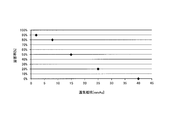
- a suction mouth sample in which an acetate filter was inserted into a polypropylene (PP) tube was prepared, and 10 subjects (adult male smokers) performed suction using the sample.
- a sample with a ventilation resistance of 2 mmAq Example 1
- a sample with a ventilation resistance of 8 mmAq Example 2
- a sample with a ventilation resistance of 15 mmAq Example 3
- a sample with a ventilation resistance of 25 mmAq Example 4
- a sample having a ventilation resistance of 40 mmAq (Comparative Example 1) was prepared. The ventilation resistance of each sample was adjusted by the length of the acetate filter.
- Example 1 For Example 1 (2 mmAq), 50% of the subjects replied that the feeling of resistance was just right (rating 3), and the remaining 50% of the subjects were slightly weak (rating 2) or weak (rating 1). I replied.
- Example 2 8 mmAq
- the ventilation resistance of the entire air flow path is preferably 25 mmAq or less. Moreover, it was confirmed that the ventilation resistance of the entire air flow path is more preferably 15 mmAq or less. Furthermore, it was confirmed that the ventilation resistance of the entire air flow path is more preferably 2 mmAq or more and 8 mmAq or less.
Priority Applications (11)
| Application Number | Priority Date | Filing Date | Title |
|---|---|---|---|
| KR1020177029447A KR102105747B1 (ko) | 2015-04-02 | 2016-03-29 | 향미 흡인기 |
| AU2016240554A AU2016240554B2 (en) | 2015-04-02 | 2016-03-29 | Flavor inhaler |
| CA2980426A CA2980426C (en) | 2015-04-02 | 2016-03-29 | Flavor inhaler |
| JP2017510059A JP6637486B2 (ja) | 2015-04-02 | 2016-03-29 | 香味吸引器 |
| EA201792196A EA036430B1 (ru) | 2015-04-02 | 2016-03-29 | Ингалятор аромата |
| CN201680019012.6A CN107404951B (zh) | 2015-04-02 | 2016-03-29 | 香味吸引器 |
| EP16772894.8A EP3275321B1 (en) | 2015-04-02 | 2016-03-29 | Flavor inhaler |
| EP23159897.0A EP4218465A3 (en) | 2015-04-02 | 2016-03-29 | Flavor inhaler |
| MYPI2017703627A MY184410A (en) | 2015-04-02 | 2016-03-29 | Flavor inhaler |
| US15/712,705 US10881137B2 (en) | 2015-04-02 | 2017-09-22 | Flavor inhaler |
| HK18105065.9A HK1245596A1 (zh) | 2015-04-02 | 2018-04-19 | 香味吸引器 |
Applications Claiming Priority (2)
| Application Number | Priority Date | Filing Date | Title |
|---|---|---|---|
| JPPCT/JP2015/060493 | 2015-04-02 | ||
| JP2015060493 | 2015-04-02 |
Related Child Applications (1)
| Application Number | Title | Priority Date | Filing Date |
|---|---|---|---|
| US15/712,705 Continuation US10881137B2 (en) | 2015-04-02 | 2017-09-22 | Flavor inhaler |
Publications (1)
| Publication Number | Publication Date |
|---|---|
| WO2016159013A1 true WO2016159013A1 (ja) | 2016-10-06 |
Family
ID=57005844
Family Applications (1)
| Application Number | Title | Priority Date | Filing Date |
|---|---|---|---|
| PCT/JP2016/060251 WO2016159013A1 (ja) | 2015-04-02 | 2016-03-29 | 香味吸引器 |
Country Status (11)
| Country | Link |
|---|---|
| US (1) | US10881137B2 (ru) |
| EP (2) | EP4218465A3 (ru) |
| JP (2) | JP6637486B2 (ru) |
| KR (1) | KR102105747B1 (ru) |
| CN (1) | CN107404951B (ru) |
| AU (1) | AU2016240554B2 (ru) |
| CA (1) | CA2980426C (ru) |
| EA (1) | EA036430B1 (ru) |
| HK (1) | HK1245596A1 (ru) |
| MY (1) | MY184410A (ru) |
| WO (1) | WO2016159013A1 (ru) |
Cited By (27)
| Publication number | Priority date | Publication date | Assignee | Title |
|---|---|---|---|---|
| KR20180070513A (ko) * | 2016-12-16 | 2018-06-26 | 주식회사 케이티앤지 | 에어로졸 형성기질을 가열하기 위한 히터 및 시스템 |
| GB2562764A (en) * | 2017-05-24 | 2018-11-28 | Robert Hopps Jason | Tobacco-containing consumable for aerosol generating devices |
| KR20190089896A (ko) * | 2016-12-19 | 2019-07-31 | 필립모리스 프로덕츠 에스.에이. | 다수의 에어로졸 형성 기재 및 액체 전달 요소를 포함하는 에어로졸 발생 시스템 |
| CN110799049A (zh) * | 2017-04-12 | 2020-02-14 | 英美烟草(投资)有限公司 | 用于使可抽吸材料挥发的装置和烟制品 |
| JP2020517235A (ja) * | 2017-04-28 | 2020-06-18 | ケーティー・アンド・ジー・コーポレーション | エアロゾル発生方法及びその装置 |
| JP2020526232A (ja) * | 2017-10-30 | 2020-08-31 | ケイティー アンド ジー コーポレイション | エアロゾル生成装置 |
| US10842954B2 (en) | 2016-12-19 | 2020-11-24 | Altria Client Services Llc | Aerosol-generating system having a cartridge with a side aperture |
| EP3563697A4 (en) * | 2017-04-24 | 2020-12-09 | Japan Tobacco Inc. | AEROSOL GENERATING DEVICE, METHOD OF CONTROLLING THE AEROSOL GENERATING DEVICE AND PROGRAM |
| EP3554290B1 (en) * | 2016-12-19 | 2020-12-30 | Philip Morris Products S.a.s. | An aerosol-generating system having a cartridge and a bypass air inlet |
| US20210007398A1 (en) * | 2016-12-19 | 2021-01-14 | Altria Client Services Llc | Aerosol-generating system comprising multiple aerosol-forming substrates and a transfer element |
| JP2021506276A (ja) * | 2017-12-15 | 2021-02-22 | アール・エイ・アイ・ストラテジック・ホールディングス・インコーポレイテッド | 複数のエアロゾル送達経路を有するエアロゾル送達装置 |
| JP2021516968A (ja) * | 2018-03-09 | 2021-07-15 | アール・エイ・アイ・ストラテジック・ホールディングス・インコーポレイテッド | 電子加熱式非燃焼型喫煙用具 |
| US11197497B2 (en) | 2017-04-11 | 2021-12-14 | Kt&G Corporation | Aerosol generating device |
| US11246345B2 (en) | 2017-04-11 | 2022-02-15 | Kt&G Corporation | Aerosol generating device provided with rotary heater |
| US11246341B2 (en) | 2016-12-16 | 2022-02-15 | Kt&G Corporation | Aerosol generation method and apparatus |
| US11252999B2 (en) | 2017-04-11 | 2022-02-22 | Kt&G Corporation | Aerosol generating device |
| US11259567B2 (en) | 2017-09-06 | 2022-03-01 | Kt&G Corporation | Aerosol generation device |
| WO2022123649A1 (ja) * | 2020-12-08 | 2022-06-16 | 日本たばこ産業株式会社 | カートリッジ |
| US11432593B2 (en) | 2017-04-11 | 2022-09-06 | Kt&G Corporation | Device for cleaning smoking member, and smoking member system |
| US11470882B2 (en) | 2017-04-11 | 2022-10-18 | Kt&G Corporation | Device for holding smoking member, and smoking member system |
| US11590302B2 (en) | 2016-12-19 | 2023-02-28 | Altria Client Services Llc | Aerosol-generating system having a cartridge and a bypass air inlet |
| US11622582B2 (en) | 2017-04-11 | 2023-04-11 | Kt&G Corporation | Aerosol generating device and method for providing adaptive feedback through puff recognition |
| US11641879B2 (en) | 2017-08-09 | 2023-05-09 | Kt&G Corporation | Aerosol generation device and control method for aerosol generation device |
| US11771138B2 (en) | 2017-04-11 | 2023-10-03 | Kt&G Corporation | Aerosol generating device and method for providing smoking restriction function in aerosol generating device |
| US11805815B2 (en) | 2017-05-26 | 2023-11-07 | Kt&G Corporation | Heater assembly and aerosol generation device comprising same |
| US11849762B2 (en) | 2017-08-09 | 2023-12-26 | Kt&G Corporation | Electronic cigarette control method and device |
| US11950622B2 (en) | 2018-09-07 | 2024-04-09 | Altria Client Services Llc | Method of making capsule including filler material infused with consumable |
Families Citing this family (25)
| Publication number | Priority date | Publication date | Assignee | Title |
|---|---|---|---|---|
| EA034513B1 (ru) * | 2015-02-27 | 2020-02-14 | Джапан Тобакко Инк. | Ароматизирующий ингалятор несгораемого типа |
| CA2980426C (en) | 2015-04-02 | 2020-09-15 | Japan Tobacco Inc. | Flavor inhaler |
| US10500354B2 (en) * | 2015-09-25 | 2019-12-10 | Sanmina Corporation | System and method for atomizing and monitoring a drug cartridge during inhalation treatments |
| CA169756S (en) | 2016-02-08 | 2017-09-01 | Nicoventures Holdings Ltd | Electronic cigarette |
| GB201605101D0 (en) | 2016-03-24 | 2016-05-11 | Nicoventures Holdings Ltd | Electronic vapour provision system |
| GB201605100D0 (en) | 2016-03-24 | 2016-05-11 | Nicoventures Holdings Ltd | Vapour provision system |
| GB201605102D0 (en) | 2016-03-24 | 2016-05-11 | Nicoventures Holdings Ltd | Mechanical connector for electronic vapour provision system |
| GB201605105D0 (en) | 2016-03-24 | 2016-05-11 | Nicoventures Holdings Ltd | Vapour provision apparatus |
| CN109476408A (zh) | 2016-07-22 | 2019-03-15 | 尼科创业控股有限公司 | 蒸汽供应装置外壳 |
| GB201700136D0 (en) | 2017-01-05 | 2017-02-22 | British American Tobacco Investments Ltd | Aerosol generating device and article |
| GB201720338D0 (en) | 2017-12-06 | 2018-01-17 | British American Tobacco Investments Ltd | Component for an aerosol-generating apparatus |
| CN108158044B (zh) * | 2018-03-12 | 2023-10-10 | 惠州市新泓威科技有限公司 | 具有双腔双气道雾化器的电子烟 |
| GB201810994D0 (en) * | 2018-07-04 | 2018-08-15 | British American Tobacco Investments Ltd | A consumable article for use with an apparatus for heating aersolisable material |
| CN110680018A (zh) * | 2019-03-31 | 2020-01-14 | 株式会社东亚产业 | 熏香芯用支承件和具有它的熏香芯 |
| EP4230066A1 (en) * | 2019-05-07 | 2023-08-23 | Philip Morris Products S.A. | Leakage prevention structure in a vaporizer device |
| KR102370535B1 (ko) | 2019-11-14 | 2022-03-04 | 강원대학교산학협력단 | 혈관외피줄기세포 배양액 또는 사이클로필린 a를 포함하는 아셔만 증후군 치료용 조성물 |
| US11744288B2 (en) | 2020-06-30 | 2023-09-05 | Altria Client Services Llc | Capsules including internal filters, heat-not-burn (HNB) aerosol-generating devices, and methods of generating an aerosol |
| KR102469765B1 (ko) * | 2020-07-22 | 2022-11-22 | 주식회사 케이티앤지 | 에어로졸 생성 장치 |
| US11789476B2 (en) | 2021-01-18 | 2023-10-17 | Altria Client Services Llc | Heat-not-burn (HNB) aerosol-generating devices including intra-draw heater control, and methods of controlling a heater |
| US11910826B2 (en) | 2021-01-18 | 2024-02-27 | Altria Client Services Llc | Heat-not-burn (HNB) aerosol-generating devices and capsules |
| CN115211587A (zh) * | 2021-04-19 | 2022-10-21 | 中国烟草总公司郑州烟草研究院 | 一种可调制香味物质释放的气溶胶发生制品及其方法 |
| CN114027566B (zh) * | 2021-11-19 | 2023-12-22 | 深圳湃科锐锋科技有限公司 | 用于电子烟校准的作业设备 |
| CN114128931A (zh) * | 2021-11-26 | 2022-03-04 | 深圳市克莱鹏科技有限公司 | 一种液体增味电子烟 |
| CN114128930A (zh) * | 2021-11-26 | 2022-03-04 | 深圳市克莱鹏科技有限公司 | 一种液体增味过滤结构及电子烟 |
| WO2023113644A1 (ru) * | 2021-12-16 | 2023-06-22 | Плонк Дмсс | Одноразовая электронная сигарета |
Citations (4)
| Publication number | Priority date | Publication date | Assignee | Title |
|---|---|---|---|---|
| WO1997048293A1 (fr) * | 1996-06-17 | 1997-12-24 | Japan Tobacco Inc. | Parfumeur d'ambiance |
| WO2013116558A1 (en) * | 2012-01-31 | 2013-08-08 | Altria Client Services Inc. | Electronic cigarette |
| WO2014156537A1 (ja) * | 2013-03-28 | 2014-10-02 | 日本たばこ産業株式会社 | 非加熱型香味吸引器 |
| JP2015504667A (ja) * | 2012-01-03 | 2015-02-16 | フィリップ・モーリス・プロダクツ・ソシエテ・アノニム | 空気流が改善されたエアロゾル発生装置及びシステム |
Family Cites Families (17)
| Publication number | Priority date | Publication date | Assignee | Title |
|---|---|---|---|---|
| GB873410A (en) * | 1958-11-11 | 1961-07-26 | Frank T Bartolomeo | Smoking simulating device |
| US4936920A (en) * | 1988-03-09 | 1990-06-26 | Philip Morris Incorporated | High void volume/enhanced firmness tobacco rod and method of processing tobacco |
| US5095921A (en) | 1990-11-19 | 1992-03-17 | Philip Morris Incorporated | Flavor generating article |
| US5479948A (en) * | 1993-08-10 | 1996-01-02 | Philip Morris Incorporated | Electrical smoking article having continuous tobacco flavor web and flavor cassette therefor |
| CA2420623C (en) * | 1993-08-10 | 2005-03-15 | Philip Morris Products Inc. | Electrical smoking article having continuous tobacco flavor web and flavor cassette therefor |
| JP2984657B2 (ja) * | 1997-07-23 | 1999-11-29 | 日本たばこ産業株式会社 | 香味発生装置 |
| CN201067079Y (zh) * | 2006-05-16 | 2008-06-04 | 韩力 | 仿真气溶胶吸入器 |
| KR101541209B1 (ko) | 2008-03-27 | 2015-07-31 | 맨카인드 코포레이션 | 건조 분말 흡입 시스템 |
| AT507187B1 (de) | 2008-10-23 | 2010-03-15 | Helmut Dr Buchberger | Inhalator |
| US9078473B2 (en) * | 2011-08-09 | 2015-07-14 | R.J. Reynolds Tobacco Company | Smoking articles and use thereof for yielding inhalation materials |
| ES2661023T3 (es) * | 2011-12-08 | 2018-03-27 | Philip Morris Products S.A. | Dispositivo generador de aerosol con flujo de aire ajustable |
| GB201216621D0 (en) * | 2012-09-18 | 2012-10-31 | British American Tobacco Co | Heading smokeable material |
| GB2507104A (en) * | 2012-10-19 | 2014-04-23 | Nicoventures Holdings Ltd | Electronic inhalation device |
| US20140190496A1 (en) | 2012-11-28 | 2014-07-10 | E-Nicotine Technology, Inc. | Methods and devices for compound delivery |
| US20150351456A1 (en) * | 2013-01-08 | 2015-12-10 | L. Perrigo Company | Electronic cigarette |
| US9993023B2 (en) | 2013-02-22 | 2018-06-12 | Altria Client Services Llc | Electronic smoking article |
| CA2980426C (en) | 2015-04-02 | 2020-09-15 | Japan Tobacco Inc. | Flavor inhaler |
-
2016
- 2016-03-29 CA CA2980426A patent/CA2980426C/en active Active
- 2016-03-29 EP EP23159897.0A patent/EP4218465A3/en active Pending
- 2016-03-29 KR KR1020177029447A patent/KR102105747B1/ko active IP Right Grant
- 2016-03-29 JP JP2017510059A patent/JP6637486B2/ja active Active
- 2016-03-29 CN CN201680019012.6A patent/CN107404951B/zh active Active
- 2016-03-29 EA EA201792196A patent/EA036430B1/ru not_active IP Right Cessation
- 2016-03-29 EP EP16772894.8A patent/EP3275321B1/en active Active
- 2016-03-29 WO PCT/JP2016/060251 patent/WO2016159013A1/ja active Application Filing
- 2016-03-29 AU AU2016240554A patent/AU2016240554B2/en active Active
- 2016-03-29 MY MYPI2017703627A patent/MY184410A/en unknown
-
2017
- 2017-09-22 US US15/712,705 patent/US10881137B2/en active Active
-
2018
- 2018-04-19 HK HK18105065.9A patent/HK1245596A1/zh unknown
-
2019
- 2019-12-19 JP JP2019229031A patent/JP6703638B2/ja active Active
Patent Citations (4)
| Publication number | Priority date | Publication date | Assignee | Title |
|---|---|---|---|---|
| WO1997048293A1 (fr) * | 1996-06-17 | 1997-12-24 | Japan Tobacco Inc. | Parfumeur d'ambiance |
| JP2015504667A (ja) * | 2012-01-03 | 2015-02-16 | フィリップ・モーリス・プロダクツ・ソシエテ・アノニム | 空気流が改善されたエアロゾル発生装置及びシステム |
| WO2013116558A1 (en) * | 2012-01-31 | 2013-08-08 | Altria Client Services Inc. | Electronic cigarette |
| WO2014156537A1 (ja) * | 2013-03-28 | 2014-10-02 | 日本たばこ産業株式会社 | 非加熱型香味吸引器 |
Non-Patent Citations (1)
| Title |
|---|
| See also references of EP3275321A4 * |
Cited By (49)
| Publication number | Priority date | Publication date | Assignee | Title |
|---|---|---|---|---|
| KR20180070513A (ko) * | 2016-12-16 | 2018-06-26 | 주식회사 케이티앤지 | 에어로졸 형성기질을 가열하기 위한 히터 및 시스템 |
| US11882870B2 (en) | 2016-12-16 | 2024-01-30 | Kt&G Corporation | Aerosol generation method and apparatus |
| KR20190019113A (ko) * | 2016-12-16 | 2019-02-26 | 주식회사 케이티앤지 | 에어로졸 형성기질을 가열하기 위한 히터 및 시스템 |
| US11457661B2 (en) | 2016-12-16 | 2022-10-04 | Kt&G Corporation | Aerosol generation method and apparatus |
| KR102033034B1 (ko) * | 2016-12-16 | 2019-10-16 | 주식회사 케이티앤지 | 에어로졸 형성기질을 가열하기 위한 히터 및 시스템 |
| US11627759B2 (en) | 2016-12-16 | 2023-04-18 | Kt&G Corporation | Aerosol generation method and apparatus |
| US11252993B2 (en) | 2016-12-16 | 2022-02-22 | Kt&G Corporation | Aerosol generation method and apparatus |
| KR102082948B1 (ko) | 2016-12-16 | 2020-04-28 | 주식회사 케이티앤지 | 에어로졸 형성기질을 가열하기 위한 히터 및 시스템 |
| US11246341B2 (en) | 2016-12-16 | 2022-02-15 | Kt&G Corporation | Aerosol generation method and apparatus |
| US11871781B2 (en) | 2016-12-16 | 2024-01-16 | Kt&G Corporation | Aerosol generation method and apparatus |
| US20210007398A1 (en) * | 2016-12-19 | 2021-01-14 | Altria Client Services Llc | Aerosol-generating system comprising multiple aerosol-forming substrates and a transfer element |
| KR102526266B1 (ko) | 2016-12-19 | 2023-04-27 | 필립모리스 프로덕츠 에스.에이. | 다수의 에어로졸 형성 기재 및 액체 전달 요소를 포함하는 에어로졸 발생 시스템 |
| EP3554289B1 (en) * | 2016-12-19 | 2023-11-22 | Philip Morris Products S.A. | Aerosol-generating system having a cartridge with a side aperture |
| EP3554290B1 (en) * | 2016-12-19 | 2020-12-30 | Philip Morris Products S.a.s. | An aerosol-generating system having a cartridge and a bypass air inlet |
| KR20190089896A (ko) * | 2016-12-19 | 2019-07-31 | 필립모리스 프로덕츠 에스.에이. | 다수의 에어로졸 형성 기재 및 액체 전달 요소를 포함하는 에어로졸 발생 시스템 |
| US11590302B2 (en) | 2016-12-19 | 2023-02-28 | Altria Client Services Llc | Aerosol-generating system having a cartridge and a bypass air inlet |
| US11724048B2 (en) | 2016-12-19 | 2023-08-15 | Altria Client Services Llc | Aerosol-generating system having a cartridge with a side aperture |
| JP2020501539A (ja) * | 2016-12-19 | 2020-01-23 | フィリップ・モーリス・プロダクツ・ソシエテ・アノニム | 複数のエアロゾル形成基体および液体移動要素を備えるエアロゾル発生システム |
| JP7066710B2 (ja) | 2016-12-19 | 2022-05-13 | フィリップ・モーリス・プロダクツ・ソシエテ・アノニム | 複数のエアロゾル形成基体および液体移動要素を備えるエアロゾル発生システム |
| US10842954B2 (en) | 2016-12-19 | 2020-11-24 | Altria Client Services Llc | Aerosol-generating system having a cartridge with a side aperture |
| US11259571B2 (en) | 2017-04-11 | 2022-03-01 | Kt&G Corporation | Aerosol generating apparatus provided with movable heater |
| US11252999B2 (en) | 2017-04-11 | 2022-02-22 | Kt&G Corporation | Aerosol generating device |
| US11246345B2 (en) | 2017-04-11 | 2022-02-15 | Kt&G Corporation | Aerosol generating device provided with rotary heater |
| US11197497B2 (en) | 2017-04-11 | 2021-12-14 | Kt&G Corporation | Aerosol generating device |
| US11622582B2 (en) | 2017-04-11 | 2023-04-11 | Kt&G Corporation | Aerosol generating device and method for providing adaptive feedback through puff recognition |
| US11771138B2 (en) | 2017-04-11 | 2023-10-03 | Kt&G Corporation | Aerosol generating device and method for providing smoking restriction function in aerosol generating device |
| US11432593B2 (en) | 2017-04-11 | 2022-09-06 | Kt&G Corporation | Device for cleaning smoking member, and smoking member system |
| US11470882B2 (en) | 2017-04-11 | 2022-10-18 | Kt&G Corporation | Device for holding smoking member, and smoking member system |
| CN110799049A (zh) * | 2017-04-12 | 2020-02-14 | 英美烟草(投资)有限公司 | 用于使可抽吸材料挥发的装置和烟制品 |
| JP2020513193A (ja) * | 2017-04-12 | 2020-05-07 | ブリティッシュ アメリカン タバコ (インヴェストメンツ) リミテッドBritish American Tobacco (Investments) Limited | 喫煙材を揮発させるための装置及び喫煙品 |
| EP3563697A4 (en) * | 2017-04-24 | 2020-12-09 | Japan Tobacco Inc. | AEROSOL GENERATING DEVICE, METHOD OF CONTROLLING THE AEROSOL GENERATING DEVICE AND PROGRAM |
| JP2020517235A (ja) * | 2017-04-28 | 2020-06-18 | ケーティー・アンド・ジー・コーポレーション | エアロゾル発生方法及びその装置 |
| US11871787B2 (en) | 2017-04-28 | 2024-01-16 | Kt&G Corporation | Aerosol generation method and apparatus |
| JP7131879B2 (ja) | 2017-04-28 | 2022-09-06 | ケーティー アンド ジー コーポレイション | エアロゾル発生方法及びその装置 |
| GB2562764A (en) * | 2017-05-24 | 2018-11-28 | Robert Hopps Jason | Tobacco-containing consumable for aerosol generating devices |
| US11805815B2 (en) | 2017-05-26 | 2023-11-07 | Kt&G Corporation | Heater assembly and aerosol generation device comprising same |
| US11641879B2 (en) | 2017-08-09 | 2023-05-09 | Kt&G Corporation | Aerosol generation device and control method for aerosol generation device |
| US11849762B2 (en) | 2017-08-09 | 2023-12-26 | Kt&G Corporation | Electronic cigarette control method and device |
| US11647785B2 (en) | 2017-09-06 | 2023-05-16 | Kt&G Corporation | Aerosol generation device having structure for preventing liquid leakage |
| US11259567B2 (en) | 2017-09-06 | 2022-03-01 | Kt&G Corporation | Aerosol generation device |
| US11344062B2 (en) | 2017-09-06 | 2022-05-31 | Kt&G Corporation | Aerosol generation device having concealed fastening portion |
| US11937631B2 (en) | 2017-09-06 | 2024-03-26 | Kt&G Corporation | Aerosol generation device having concealed fastening portion |
| JP2020526232A (ja) * | 2017-10-30 | 2020-08-31 | ケイティー アンド ジー コーポレイション | エアロゾル生成装置 |
| JP7297755B2 (ja) | 2017-12-15 | 2023-06-26 | アール・エイ・アイ・ストラテジック・ホールディングス・インコーポレイテッド | 複数のエアロゾル送達経路を有するエアロゾル送達装置 |
| JP2021506276A (ja) * | 2017-12-15 | 2021-02-22 | アール・エイ・アイ・ストラテジック・ホールディングス・インコーポレイテッド | 複数のエアロゾル送達経路を有するエアロゾル送達装置 |
| JP2021516968A (ja) * | 2018-03-09 | 2021-07-15 | アール・エイ・アイ・ストラテジック・ホールディングス・インコーポレイテッド | 電子加熱式非燃焼型喫煙用具 |
| JP7463283B2 (ja) | 2018-03-09 | 2024-04-08 | アール・エイ・アイ・ストラテジック・ホールディングス・インコーポレイテッド | 電子加熱式非燃焼型喫煙用具 |
| US11950622B2 (en) | 2018-09-07 | 2024-04-09 | Altria Client Services Llc | Method of making capsule including filler material infused with consumable |
| WO2022123649A1 (ja) * | 2020-12-08 | 2022-06-16 | 日本たばこ産業株式会社 | カートリッジ |
Also Published As
| Publication number | Publication date |
|---|---|
| HK1245596A1 (zh) | 2018-08-31 |
| CA2980426C (en) | 2020-09-15 |
| EA201792196A1 (ru) | 2018-02-28 |
| JP2020048574A (ja) | 2020-04-02 |
| CN107404951A (zh) | 2017-11-28 |
| EP3275321A1 (en) | 2018-01-31 |
| AU2016240554A1 (en) | 2017-10-12 |
| JP6637486B2 (ja) | 2020-01-29 |
| JPWO2016159013A1 (ja) | 2017-08-03 |
| EP4218465A3 (en) | 2023-08-09 |
| KR102105747B1 (ko) | 2020-04-28 |
| CN107404951B (zh) | 2020-03-03 |
| JP6703638B2 (ja) | 2020-06-03 |
| EA036430B1 (ru) | 2020-11-10 |
| US10881137B2 (en) | 2021-01-05 |
| EP4218465A2 (en) | 2023-08-02 |
| MY184410A (en) | 2021-04-01 |
| EP3275321A4 (en) | 2018-12-12 |
| US20180007960A1 (en) | 2018-01-11 |
| AU2016240554B2 (en) | 2019-09-19 |
| KR20170128492A (ko) | 2017-11-22 |
| CA2980426A1 (en) | 2016-10-06 |
| EP3275321B1 (en) | 2023-05-03 |
Similar Documents
| Publication | Publication Date | Title |
|---|---|---|
| JP6703638B2 (ja) | 香味吸引器 | |
| TWI679942B (zh) | 香味吸嚐器 | |
| JP6606178B2 (ja) | 非燃焼型香味吸引器、香喫味源ユニット及び霧化ユニット | |
| US9730473B2 (en) | Non-burning type flavor inhaler and capsule unit | |
| JP6511073B2 (ja) | 非燃焼型香味吸引器、香味源ユニット及び非燃焼型香味吸引器用部材の製造方法 | |
| CN107072310B (zh) | 烟弹以及非燃烧型香味吸取器 | |
| CN107530511B (zh) | 非燃烧型香味抽吸器 | |
| WO2015167001A1 (ja) | 非燃焼型香味吸引器 | |
| KR20180083312A (ko) | 전자 흡연 부분과 전자 흡연 장치, 및 그 제조 방법 | |
| TWI581725B (zh) | 香味吸嚐器 | |
| TWI689261B (zh) | 加熱型香味吸嚐器 | |
| TWI618493B (zh) | 非燃燒型香味吸嚐器、香吸嚐味源單元及霧化單元 |
Legal Events
| Date | Code | Title | Description |
|---|---|---|---|
| 121 | Ep: the epo has been informed by wipo that ep was designated in this application |
Ref document number: 16772894 Country of ref document: EP Kind code of ref document: A1 |
|
| ENP | Entry into the national phase |
Ref document number: 2017510059 Country of ref document: JP Kind code of ref document: A |
|
| ENP | Entry into the national phase |
Ref document number: 2980426 Country of ref document: CA |
|
| NENP | Non-entry into the national phase |
Ref country code: DE |
|
| ENP | Entry into the national phase |
Ref document number: 2016240554 Country of ref document: AU Date of ref document: 20160329 Kind code of ref document: A |
|
| ENP | Entry into the national phase |
Ref document number: 20177029447 Country of ref document: KR Kind code of ref document: A |
|
| WWE | Wipo information: entry into national phase |
Ref document number: 201792196 Country of ref document: EA |