WO2016158132A1 - 電動工具 - Google Patents
電動工具 Download PDFInfo
- Publication number
- WO2016158132A1 WO2016158132A1 PCT/JP2016/055842 JP2016055842W WO2016158132A1 WO 2016158132 A1 WO2016158132 A1 WO 2016158132A1 JP 2016055842 W JP2016055842 W JP 2016055842W WO 2016158132 A1 WO2016158132 A1 WO 2016158132A1
- Authority
- WO
- WIPO (PCT)
- Prior art keywords
- voltage
- battery
- battery pack
- remaining capacity
- electric tool
- Prior art date
- Legal status (The legal status is an assumption and is not a legal conclusion. Google has not performed a legal analysis and makes no representation as to the accuracy of the status listed.)
- Ceased
Links
Images




Classifications
-
- B—PERFORMING OPERATIONS; TRANSPORTING
- B25—HAND TOOLS; PORTABLE POWER-DRIVEN TOOLS; MANIPULATORS
- B25F—COMBINATION OR MULTI-PURPOSE TOOLS NOT OTHERWISE PROVIDED FOR; DETAILS OR COMPONENTS OF PORTABLE POWER-DRIVEN TOOLS NOT PARTICULARLY RELATED TO THE OPERATIONS PERFORMED AND NOT OTHERWISE PROVIDED FOR
- B25F5/00—Details or components of portable power-driven tools not particularly related to the operations performed and not otherwise provided for
-
- H—ELECTRICITY
- H01—ELECTRIC ELEMENTS
- H01M—PROCESSES OR MEANS, e.g. BATTERIES, FOR THE DIRECT CONVERSION OF CHEMICAL ENERGY INTO ELECTRICAL ENERGY
- H01M10/00—Secondary cells; Manufacture thereof
- H01M10/42—Methods or arrangements for servicing or maintenance of secondary cells or secondary half-cells
- H01M10/44—Methods for charging or discharging
-
- H—ELECTRICITY
- H02—GENERATION; CONVERSION OR DISTRIBUTION OF ELECTRIC POWER
- H02J—ELECTRIC POWER NETWORKS; CIRCUIT ARRANGEMENTS OR SYSTEMS FOR SUPPLYING OR DISTRIBUTING ELECTRIC POWER; SYSTEMS FOR STORING ELECTRIC ENERGY
- H02J7/00—Circuit arrangements for charging or discharging batteries or for supplying loads from batteries
-
- Y—GENERAL TAGGING OF NEW TECHNOLOGICAL DEVELOPMENTS; GENERAL TAGGING OF CROSS-SECTIONAL TECHNOLOGIES SPANNING OVER SEVERAL SECTIONS OF THE IPC; TECHNICAL SUBJECTS COVERED BY FORMER USPC CROSS-REFERENCE ART COLLECTIONS [XRACs] AND DIGESTS
- Y02—TECHNOLOGIES OR APPLICATIONS FOR MITIGATION OR ADAPTATION AGAINST CLIMATE CHANGE
- Y02E—REDUCTION OF GREENHOUSE GAS [GHG] EMISSIONS, RELATED TO ENERGY GENERATION, TRANSMISSION OR DISTRIBUTION
- Y02E60/00—Enabling technologies; Technologies with a potential or indirect contribution to GHG emissions mitigation
- Y02E60/10—Energy storage using batteries
Definitions
- the present invention relates to an electric tool using a secondary battery as a drive source.
- Patent Document 1 describes that a remaining capacity display LED is provided in the battery pack.
- the remaining capacity when the battery pack is provided with means for displaying the remaining capacity, the remaining capacity may be displayed based on battery characteristics such as the battery voltage of the secondary battery, for example.
- the remaining capacity display means may be provided on the electric tool side.
- an electric tool driven by a battery pack having a nominal voltage of 18V is configured to be driven even if a battery pack having a nominal voltage of 14.4V is connected.
- the remaining capacity display means is provided on the electric tool side in such a configuration, the remaining capacity is displayed in accordance with the battery pack having a nominal voltage of 18V. Therefore, it is difficult to display an accurate remaining capacity when a battery pack having a nominal voltage of 14.4 V is connected.
- the present invention provides a terminal for battery pack identification in an electric tool capable of selectively connecting a plurality of battery packs of different types (nominal voltages) (for example, battery voltages (nominal voltages) of 14.4 V and 18 V). It is an object of the present invention to provide an electric tool capable of performing control corresponding to a connected battery pack with an inexpensive and simple configuration without providing the above. It is another object of the present invention to provide an electric tool that can determine the nominal voltage of a connected battery pack with an inexpensive and simple configuration. It is another object of the present invention to provide a power tool that can display the remaining capacity on a display means provided on the power tool side in accordance with the nominal voltage of the battery pack with an inexpensive and simple configuration.
- nominal voltages for example, battery voltages (nominal voltages) of 14.4 V and 18 V.
- an electric tool capable of selectively connecting a plurality of battery packs having different numbers of cells provided in the battery pack, from the voltage between the positive electrode terminal and the negative electrode terminal of the battery pack, It has a battery voltage detection part which detects battery voltage, and a control part which controls the power tool according to the nominal voltage of the battery pack based on the detected battery voltage.
- the electric tool which can perform control corresponding to the connected battery pack with an inexpensive and simple structure can be provided.
- the battery voltage (nominal voltage) of the connected battery pack can be determined with an inexpensive and simple configuration.
- the remaining capacity can be displayed on the display means provided on the power tool side according to the nominal voltage of the battery pack with an inexpensive and simple configuration.
- FIG. 1 is a circuit block diagram showing a connection state between a power tool and a battery pack according to the present invention, and the power tool 1 is detachably connected to a battery pack 20.
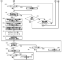
- FIG. 2 is an example of a control flowchart of the electric power tool 1.
- the electric tool 1 is connected in series with the motor 2, the trigger switch 3 that is operated by the user to operate the motor 2, and the motor 2, and the battery pack 20 is overdischarged, overloaded, and in a high temperature state as will be described later.
- the discharge interruption means 4 (for example, FET) for interrupting
- the electric tool 1 includes a microcomputer 5 (hereinafter referred to as a microcomputer) serving as a control unit for controlling the discharge interruption means 4 and the like, a storage unit 6 provided in the microcomputer 5, and a constant voltage circuit for generating a power source for the microcomputer 5.
- Power supply control means 7 for controlling 8.
- the electric power tool 1 detects the battery voltage detection means 9 for detecting the battery voltage of the connected battery pack 20 by the voltage between the positive terminal 17 and the negative terminal 19 and the current flowing through the motor 2 (battery pack 20).
- a current detecting element 10 made of a shunt resistor, and current detecting means 11 for detecting a current by a voltage drop of the current detecting element 10.
- the battery pack 20 includes a discharge cutoff signal receiving unit 12 that receives a discharge cutoff signal output from the electric pack 20 when the battery pack 20 is in any of an overdischarge state, an overload state, and a high temperature state.
- the reception state of the interruption signal is input to the microcomputer 5, and the microcomputer 5 interrupts the discharge interruption means 4 when the discharge interruption signal is input.
- the electric power tool 1 includes a display unit 13 for displaying the remaining capacity of the battery pack 20 and a display switch 16 for operating display / non-display of the display unit 13.
- the display unit 13 has two LEDs 14 and 15, and when the microcomputer 5 detects that the display switch 16 has been pressed, the remaining capacity is displayed on the display unit 13 for a predetermined time by a signal from the microcomputer 5. Yes.
- the battery pack 20 is connected to the electric power tool 1 through three terminals of a positive electrode terminal 17, a discharge interruption signal transmission terminal 18 and a negative electrode terminal 19.
- the electric power tool 1 is not provided with an identification terminal for identifying the type (nominal voltage or the like) of the battery pack 20 to be connected.
- a method for determining the type of the battery pack 20 will be described later.
- Battery pack The battery pack 20 has one or a plurality of battery cells 21, and in this embodiment, four battery cells 21 are connected in series, and the nominal voltage is 14.4V (rated 3.6V / cell ⁇ 4). ).
- the protection IC 22 monitors the voltage of each of a plurality of battery cells connected in series.
- the protection IC 22 determines that the battery pack 20 (battery cell) has been overdischarged and outputs an abnormal signal (discharge cutoff signal) from a predetermined port. ) Is output.
- the abnormal signal is transmitted to the microcomputer 5 on the electric power tool 1 side through the discharge cutoff signal transmission terminal 18 and the discharge cutoff signal receiver 12, and the microcomputer 5 shuts down the discharge cutoff means 4 and stops the discharge of the battery pack 20.
- the electric tool in this invention shall be the structure which can connect both the lithium ion battery (battery pack) of a nominal voltage 14.4V and 18V.
- the present invention is not limited to this, and a battery pack having a nominal voltage lower than 14.4V or a nominal voltage higher than 18V may be connectable.
- a temperature detection means 23 made of a thermistor or the like is provided in the vicinity of the battery cell 21 to detect the temperature of the battery cell 21.
- the protection IC 22 outputs an abnormal signal.
- the abnormal signal is transmitted to the microcomputer 5 on the electric power tool 1 side through the discharge cutoff signal transmission terminal 18 and the discharge cutoff signal receiving unit 12, and the microcomputer 5 shuts down the discharge cutoff means 4 and stops the discharge of the battery pack 20.
- the battery pack 20 is also provided with a current detection means 24 comprising a shunt resistor, and the protection IC 22 can detect the voltage drop.
- the protection IC 22 In the overload state where the voltage drop of the shunt resistor 24 is equal to or greater than a predetermined value, that is, the discharge current is equal to or greater than the predetermined value, the protection IC 22 outputs an abnormal signal. As a result, the microcomputer 5 stops discharging the battery pack 20 as described above.
- the power supply control means 7 is configured to turn on the constant voltage circuit 8, and the battery pack 20 Is supplied to the microcomputer 5 through the constant voltage circuit 8.
- the microcomputer 5 outputs a predetermined signal from a predetermined port to the power supply control means 7 as soon as power is supplied.
- the power supply control means 7 is configured to turn on the constant voltage circuit 8 when the trigger switch 3 is operated.
- the power supply control means 7 is configured to turn on the constant voltage circuit 8 even with a predetermined signal output from 5 to the power supply control means 7.
- the microcomputer 5 detects the battery voltage of the battery pack 20 under no load by the battery voltage detection means 9 (Ste 102).
- the microcomputer 5 detects the battery voltage of the battery pack 20 when no load is detected by the battery voltage detection means 9 after the microcomputer 5 is activated. .
- the microcomputer 5 outputs a predetermined signal to the discharge interruption means 4 to turn on the discharge interruption means 4 (step 103). Then, when the user operates (turns on) the trigger switch 3, a discharge path passing through the battery pack 20, the trigger switch 3, the motor 2, the discharge interruption means 4, and the current detection element 10 is formed, and the electric tool 1 (motor 2) is Start operation. Since the trigger switch 3 does not know at which timing it is operated by the user, the trigger switch 3 is configured to detect the no-load voltage V0 (step 102) before the motor 2 is started.
- the type (nominal voltage) of the battery pack 20 connected to the electric power tool 1 is determined.
- the type (nominal voltage) is determined from the battery voltage of the battery pack 20.
- the microcomputer 5 discriminates the battery pack 20 based on the battery discrimination result at the time of previous use of the tool stored in the internal storage means 6 (step 104).
- the battery discrimination result stored in the storage unit 6 will be described later.
- step 102 from the battery voltage V0 at no load detected by the battery voltage detecting means 9 and the previous battery discrimination result stored in the storage means 6 discriminated in step 104, the current battery pack A determination is made (step 105).
- the cell voltage when the lithium ion battery is fully charged is about 4.2V.
- the 14.4V lithium-ion battery has four cells, and the 18V lithium-ion battery has five cells connected in series. Therefore, the upper limit value of the battery voltage in the case of the battery pack having the nominal voltage of 14.4V is 16.8V (4.2V ⁇ 4), and the upper limit value in the case of the nominal voltage of 14.4V is 21V (4.2V ⁇ 5). ). Accordingly, when the no-load battery voltage V0 detected by the battery voltage detection means 9 is 16.8V or higher, the battery pack having a nominal voltage of 18V is used regardless of the type of battery pack stored in the storage means 6. Can be determined to be connected. In addition, since the cell voltage at the time of full charge changes with cell makers etc., it is not restricted to 4.2V.
- the remaining capacity is considerably reduced. If the battery voltage is 14.4V or less (3.6V x 4) in a battery pack with a nominal voltage of 14.4V, the remaining capacity is small, and the battery voltage is 18V or less (3.6V x in a battery pack with a nominal voltage of 18V). 5), it can be determined that the remaining capacity is small. Therefore, when the no-load battery voltage V0 detected by the battery voltage detecting means 9 is 14.4 V or less, it is determined that the battery pack has a small remaining capacity no matter which battery pack is connected. be able to. Note that the cell voltage determined to have a small remaining capacity is not limited to 3.6V.
- storage means 6 is a battery pack connected when using the tool last time.
- the battery pack and the electric tool are often used as a set. For this reason, if it is difficult to accurately determine which battery pack is connected, the battery pack used last time is likely to be connected, so it is temporarily stored in the storage means 6. It is determined that the battery pack is connected. Then, these determination results are stored in the storage means 6 (step 106).
- step 105 when it is determined that the battery pack V0 when the no-load battery voltage V0 is 16.8V or more is 18V, and the battery voltage V0 is 14.4V or less and the remaining capacity is low (the nominal voltage is If it is determined, the process skips to step 123 (step 107).
- step 105 when the battery voltage V0 at no load is between 14.4V and 16.8V and the connected battery pack cannot be accurately determined (when it is determined that the battery pack was used last time), It is determined whether or not the display switch 16 has been operated (turned on) by the user (step 108). If it is determined in step 108 that the display switch 16 has been operated (turned on), the current remaining capacity is displayed on the display unit 13 for a predetermined time (step 109).
- the display unit 13 is composed of two LEDs 14 and 15.
- the remaining capacity is large when two LEDs are lit, and the remaining capacity when one LED is lit. When the capacity is medium and both LEDs are turned off, it is defined that the remaining capacity is small.
- a three-level display is assigned for each range of the battery voltage. An example of the remaining capacity display for each battery voltage range is shown in FIG. In a battery pack with a nominal voltage of 18V, the remaining capacity is large when it is 19.5V or more, the remaining capacity is medium when it is 18V to 19.5V, and the remaining capacity is small when it is 18V or less. To do.
- the remaining capacity is large when it is 15.6V or higher, the remaining capacity is medium when it is 14.4V to 15.6V, and the remaining capacity when it is 14.4V or less. Is small. If the battery pack connected in step 107 cannot be accurately determined, the remaining capacity is displayed based on the nominal voltage of the battery pack used last time.
- a discharge cutoff signal is detected via the discharge cutoff signal receiving unit 12 (step 110).
- the discharge cutoff signal is output from the battery pack 20.
- the battery pack 20 monitors each cell voltage of the battery cell 21 with the protection IC 22, and the protection IC 22 determines that an overdischarge state occurs even when one of the cells drops to a voltage equal to or lower than a predetermined value, and determines a predetermined signal ( (Abnormal signal) is output.
- the predetermined signal (abnormal signal) is input to the microcomputer 5 via the discharge cutoff signal transmission terminal 18 and the discharge cutoff signal receiver 12.
- the microcomputer 5 shuts off the FET 4 (outputs a means signal to the FET 4) and stops the discharge (step 111).
- an abnormal state other than the overdischarge state is also detected. That is, when the temperature detection means 23 installed in the battery pack 20 detects a value equal to or higher than a predetermined battery temperature, or the current detection means 24 provided in the battery pack 20 detects a value higher than a predetermined current value.
- the protection IC 22 determines that it is in an abnormal state (high temperature state, overload state), outputs a predetermined signal (abnormal signal) as in the overdischarge state, and stops the discharge in step 111. If any one of these three abnormal conditions occurs, the discharge (motor) is stopped at step 111.
- step 112 when the user operates the trigger switch 3 and the motor 2 operates, whether or not a current flows through the current detection element 10 (discharge path) is detected and determined by the current detection means 11 (step 112). ). If no current is detected in step 112 (NO in step 112), the process returns to step 108. If current is detected in step 112 (YES in step 112), the remaining capacity of the current battery pack 20 is displayed on the display unit 13 in accordance with the operation of the display switch 16, as in the operations in steps 108 and 109. (Steps 113 and 114).
- a current is detected in step 112, and it is determined whether or not a predetermined time has elapsed (step 115). If the user stops working before a predetermined time (for example, 5 seconds) has elapsed (trigger switch 3 is turned off) and no current flows through the discharge path (non-detection state) (YES in step 116) Return to step. If a discharge interruption signal (abnormal signal) is detected before the predetermined time has elapsed (YES in step 117), the FET 4 is interrupted in step 111 to stop the discharge. If the discharge interruption signal is not detected in step 117, the process returns to step 113 to continue the discharge.
- a predetermined time for example, 5 seconds
- step 118 an average current value I1 from the current detection to the elapse of the predetermined time is calculated (step 118), and the average voltage V1 from the current detection to the elapse of the predetermined time is calculated. Is calculated (step 119).
- a difference ⁇ V ( V0 ⁇ V1) between the no-load voltage V0 before the current detected in step 102 flows and the average voltage V1 calculated in step 119 is calculated (step 120).
- step 121 the type (nominal voltage) of the battery pack is determined based on the degree of voltage drop.
- a certain quadratic function is set.
- a ⁇ I1 (a is a constant) proportional to the current I1
- ⁇ V ⁇ a ⁇ I1 (a is a constant) proportional to the current I1
- the predetermined value is not limited to the above-described value (a ⁇ I1), and a set value for determining a difference in voltage drop may be appropriately determined. Since the electric tool 1 has a different load depending on work and the magnitude of the flowing current, the type of the battery pack is determined based on the change in current.
- step 123 it is determined whether or not a discharge interruption signal (abnormal signal) has been detected, and when detected (YES in step 123), the FET 4 is interrupted (step 124).
- the electric tool side To realize control according to the type of battery pack connected with an inexpensive and simple configuration without providing a configuration (for example, a terminal for type identification) that discriminates the type (for example, nominal voltage) of the battery pack. Can do.
- the nominal voltage of the battery pack can be determined based on the battery voltage.
- the remaining capacity can be accurately displayed on the remaining capacity display means such as an LED provided on the electric tool side in accordance with the nominal voltage. Further, considering that the battery pack and the electric tool are usually used as a set, the battery pack (nominal voltage) at the previous use is stored.
- the nominal voltage can be provisionally determined and the remaining capacity can be displayed.
- the remaining capacity is small, the small remaining capacity is displayed regardless of the nominal voltage of the battery pack, so that replacement or charging of the battery pack can be promoted.
- the battery pack is identified when the connected battery pack 20 is in a battery voltage range (14.4 V to 16.8 V) where it cannot be determined whether the battery pack has a nominal voltage of 14.4 V or 18 V.
- the method that is, steps 118 to 122 in the control flowcharts of FIGS. 2 and 3 are different from those of the first embodiment.
- Other steps and the circuit block diagram of FIG. 1 and FIGS. 4 and 5 are the same as those of the first embodiment, and thus detailed description thereof is omitted.
- step 201 When the user operates the trigger switch 3 or connects the battery pack 20, the steps 101 to 117 in FIG. 2 and FIG. 3 are executed in step 200 along the control flowchart in FIG. If a predetermined time has elapsed since the current was detected in step 115 (YES in step 115), the process proceeds to step 201.
- the battery voltage detection means 9 detects the current battery voltage V2 of the battery pack 20.
- the battery voltage threshold value b is set, and whether or not the battery voltage V2 after flowing the current for a predetermined time (for example, 5 seconds) becomes equal to or lower than the predetermined voltage (threshold value) is nominal.
- the battery pack having a voltage of 14.4V and 18V is discriminated. If the battery pack has a nominal voltage of 18V, the voltage drops considerably. Therefore, when the battery voltage V2 drops below the predetermined voltage b, it is determined that the battery pack has the nominal voltage 18V, and the battery voltage V2 is larger than the predetermined voltage b. Is distinguished from a battery pack having a nominal voltage of 14.4V.
- step 204 steps 123 to 128 are executed as in the first embodiment. From the above, the same effects as in the first embodiment can be obtained in the second embodiment.
- the third embodiment also has a battery voltage range (14.4 V to 16.8 V) in which the connected battery pack 20 cannot be distinguished from the nominal voltage 14.4V or 18V.
- the battery pack discriminating method in a certain case is different from the above-described first and second embodiments. That is, steps 118 to 122 (FIG. 3) of the control flowchart of the first embodiment and steps 201 to 203 of the control flowchart of the first embodiment are different.
- the battery pack is determined based on the difference ⁇ V between the battery voltage V0 in the no-load state and the battery voltage V1 after discharging for a predetermined time.
- the battery voltage V2 after discharging for a predetermined time is used.
- the battery pack was determined based on the comparison between the threshold value b and the threshold value b. That is, in these embodiments, the battery pack is determined based on the voltage drop after discharging for a predetermined time. However, depending on the environmental temperature at which the user works, the number of times the battery pack is used, etc., it is assumed that the voltage drop will vary even if the battery pack has the same nominal voltage.
- the third embodiment is the same in that the battery pack is discriminated based on the voltage drop, but the voltage drop is detected according to the discharge capacity, not after a predetermined time (time) after discharging the voltage drop detection timing. It was made to detect.
- FIG. 7 shows changes in battery voltage with respect to discharge capacity (consumption) of battery packs having different nominal voltages.
- Battery pack A is a battery pack having a nominal voltage of 18V
- battery pack B is a battery pack having a nominal voltage of 14.4V.
- W1 discharge capacity
- the type (nominal voltage) of the battery pack is determined based on the battery voltage when the predetermined discharge capacity is reached, and this will be described using the control flowchart of FIG. Detailed description of the same processing as in the first or second embodiment will be omitted.
- step 301 the microcomputer 5 determines whether or not the trigger switch 3 is turned on. For example, whether or not the trigger switch 3 is on is determined by detecting whether or not current is flowing through the discharge path by the current detection element 10 and the current detection means 11. Note that the state of the trigger switch 3 may be determined directly by the microcomputer 5.
- the discharge amount (discharge capacity) is measured at a predetermined cycle (for example, 1 second cycle) in step 302.
- a predetermined cycle for example, 1 second cycle
- a predetermined time for example, 5 seconds
- W1 for example, 300 mAh
- the discharge amount of 300 mAh is a light load work of about 216 seconds at a discharge current of 5 A, a medium load work of about 108 seconds at a discharge current of 10 A, a discharge current of about 20 seconds at 20 A, and a discharge current of 30 A. This corresponds to a high load work of about 36 seconds.
- step 305 If the discharge amount has consumed a predetermined amount, it is determined in step 305 whether or not the battery voltage is 14 V or higher. As shown in FIG. 7, in the case of the battery pack B having a nominal voltage of 14.4 V, the battery voltage is hardly lowered even when 300 mAh is discharged. On the other hand, in the case of the battery pack A having a nominal voltage of 18V, the battery voltage is remarkably lowered even with the same discharge amount. Therefore, if the battery voltage is 14V or higher in step 305, it is determined as a battery pack having a nominal voltage of 14.4V (step 306), and the determination result is stored in the storage means 6 (step 307). Then, in step 308, the processing in steps 123 to 128 in FIG.
- step 301 if NO in steps 303 to 305, the process returns to step 301.
- NO in steps 304 and 305 it is not determined that the battery pack has a nominal voltage of 18V. Therefore, when the display switch 16 is operated, the remaining capacity is displayed based on the battery pack stored in step 106. As shown in FIG. 7, when discharging is performed, the battery voltage is remarkably lowered, and in some cases, 300 mAh cannot be discharged. Further, when the battery voltage is low, a difference in voltage drop due to a difference in nominal voltage is less likely to occur. Therefore, if NO in steps 304 and 305, it is not determined that the battery pack has a nominal voltage of 18V.
- the battery pack has a nominal voltage of 18V without considering the above-described problem. It is also possible to determine a battery pack having a nominal voltage of 18V by setting a predetermined discharge amount W1 to be small (for example, 200 mAh) to prevent a state in which a predetermined amount of discharge cannot be performed. From the above, the same effects as in the first embodiment can be obtained in the third embodiment. Furthermore, by considering the discharge amount, it is possible to more accurately determine the battery pack.
Landscapes
- Engineering & Computer Science (AREA)
- Manufacturing & Machinery (AREA)
- Chemical & Material Sciences (AREA)
- Chemical Kinetics & Catalysis (AREA)
- Electrochemistry (AREA)
- General Chemical & Material Sciences (AREA)
- Mechanical Engineering (AREA)
- Power Engineering (AREA)
- Secondary Cells (AREA)
- Charge And Discharge Circuits For Batteries Or The Like (AREA)
Abstract
公称電圧が異なる複数の電池パックを択一的に接続可能な電動工具において、電池パック識別用の端子等を設けずに安価且つ簡易な構成で、接続された電池パックに対応した制御を行うことができる電動工具を提供することを目的としている。電池パック内に設けられたセルの数が異なる複数の電池パックを択一的に接続可能な電動工具において、前記電池パックの正極端子と負極端子との間の電圧から電池電圧を検出する電池電圧検出部と、検出した前記電池電圧に基づいた前記電池パックの公称電圧に応じて前記電動工具を制御する制御部と、を有する。
Description
本発明は、二次電池を駆動源とした電動工具に関する。
二次電池を有する電池パックを駆動源とする電動工具が広く普及している。電動工具で使用中の電池パックが、残りどの程度使用できるかの目安として二次電池の残容量を知りたいという要望がある。残容量を表示する手段として、特許文献1には電池パックに残容量表示LEDを設けたことが記載されている。
特許文献1に記載のように、電池パックに残容量を表示する手段が設けられている場合、例えば二次電池の電池電圧等の電池特性に基づいて残容量を表示すればよい。しかしながら、電動工具側に残容量表示手段が設けられている場合もある。
従来から、複数の電圧の電池パックを択一的に接続可能な電動工具がある。具体的には、公称電圧18Vの電池パックで駆動する電動工具は公称電圧14.4Vの電池パックを接続しても駆動できるように構成されている。このような構成で電動工具側に残容量表示手段が設けられている場合は公称電圧18Vの電池パックに合わせて残容量が表示される構成となる。そのため、公称電圧14.4Vの電池パックが接続された場合には正確な残容量を表示することが困難である。
接続された電池パックの種類を電動工具側で判別するために、充電器と同じように、電動工具側に種類識別用の端子を設ける構成とすれば、判別された電池パックの種類に応じて残容量を表示することができる。しかしながら、電池パックの種類を判別するための識別端子を設ける必要があるため、端子の設置スペースやコストの点で不利である。
そこで本発明は、種類(公称電圧)が異なる複数の電池パック(例えば電池電圧(公称電圧)が14.4V及び18V等)を択一的に接続可能な電動工具において、電池パック識別用の端子等を設けずに安価且つ簡易な構成で、接続された電池パックに対応した制御を行うことができる電動工具を提供することを目的としている。また、安価且つ簡易な構成で、接続された電池パックの公称電圧を判別することができる電動工具を提供することを目的としている。また、安価且つ簡易な構成で、電池パックの公称電圧に応じて電動工具側に設けられた表示手段に残容量を表示することができる電動工具を提供することを目的としている。
上記目的を達成するため、電池パック内に設けられたセルの数が異なる複数の電池パックを択一的に接続可能な電動工具において、前記電池パックの正極端子と負極端子との間の電圧から電池電圧を検出する電池電圧検出部と、検出した前記電池電圧に基づいた前記電池パックの公称電圧に応じて前記電動工具を制御する制御部と、を有することを特徴とする。
本発明によれば、安価且つ簡易な構成で、接続された電池パックに対応した制御を行うことができる電動工具を提供することができる。また、安価且つ簡易な構成で、接続された電池パックの電池電圧(公称電圧)を判別することができる。また、安価且つ簡易な構成で、電池パックの公称電圧に応じて電動工具側に設けられた表示手段に残容量を表示することができる。
本発明の実施の形態1について、以下図1~図5を用いて説明する。図1は本発明となる電動工具と電池パックとの接続状態を示す回路ブロック図であり、電動工具1は電池パック20と着脱可能に接続される。図2は電動工具1の制御フローチャートの一例である。
まず電動工具1の構成を説明する。電動工具1は、モータ2と、ユーザーにより操作されてモータ2を動作させるトリガスイッチ3と、モータ2と直列に接続され、後述するように電池パック20が過放電状態、過負荷状態、高温状態のいずれかの状態になった際に放電経路を遮断するための放電遮断手段4(例えばFET)を有する。更に電動工具1は、放電遮断手段4等を制御する制御部となるマイクロコンピュータ5(以下マイコン)と、マイコン5の内部に設けられた記憶部6と、マイコン5の電源を生成する定電圧回路8を制御する電源制御手段7とを有する。
更に電動工具1は、接続された電池パック20の電池電圧を正極端子17と負極端子19との間の電圧により検出する電池電圧検出手段9と、モータ2(電池パック20)に流れる電流を検出するシャント抵抗からなる電流検出素子10と、電流検出素子10の電圧降下によって電流を検出する電流検出手段11とを有する。更に、電池パック20が過放電状態、過負荷状態、高温状態のいずれかの状態になった際に電パック20から出力される放電遮断信号を受信する放電遮断信号受信部12を有し、放電遮断信号の受信状態をマイコン5に入力し、放電遮断信号が入力された場合にマイコン5は放電遮断手段4を遮断する。
更に電動工具1は、電池パック20の残容量を表示するための表示部13と、表示部13の表示/非表示を操作する表示スイッチ16とを有する。表示部13は2つのLED14、15を有し、表示スイッチ16を押したことをマイコン5が検知すると、マイコン5からの信号により所定時間、表示部13に残容量が表示される構成になっている。
次に電池パック20の構成を説明する。電池パック20は正極端子17、放電遮断信号伝達端子18及び負極端子19の3つの端子を介して電動工具1と接続される。ここで、電動工具1は、接続される電池パック20の種類(公称電圧等)を識別するための識別端子は設けられていない。なお、電池パック20の種類の判別方法は後述する。電池パック電池パック20は単数又は複数の電池セル21を有し、本実施の形態では4本の電池セル21が直列に接続され、公称電圧は14.4V(定格3.6V/セル×4本)である。保護IC22は、複数直列に接続された複数の電池セルの各セルの電圧を監視する。複数のセルの中の少なくとも1つのセル電圧が所定の電圧以下に低下した合、保護IC22は電池パック20(電池セル)が過放電になったと判別して所定のポートから異常信号(放電遮断信号)を出力する。異常信号は、放電遮断信号伝達端子18及び放電遮断信号受信部12を介して電動工具1側のマイコン5に伝達され、マイコン5は放電遮断手段4を遮断して電池パック20の放電を停止するように構成されている。なお、本発明における電動工具は、公称電圧14.4Vと18Vのリチウムイオン電池(電池パック)の両方を接続可能な構成であるものとする。但し、これに限るものではなく、14.4Vより低い公称電圧、又は18Vより高い公称電圧の電池パックを接続可能としてもよい。
また、電池セル21の近傍にはサーミスタ等からなる温度検出手段23が設けられており、電池セル21の温度を検知する。電池セル21の温度が所定温度以上の高温状態になった場合、保護IC22は異常信号を出力する。異常信号は放電遮断信号伝達端子18及び放電遮断信号受信部12を介して電動工具1側のマイコン5に伝達され、マイコン5は放電遮断手段4を遮断して電池パック20の放電を停止する。電池パック20内にもシャント抵抗からなる電流検出手段24が設けられており、その電圧降下を保護IC22が検知可能に構成されている。シャント抵抗24の電圧降下が所定値以上、すなわち放電電流が所定値以上流れている過負荷状態である場合、保護IC22は異常信号を出力する。その結果、上述したようにマイコン5は電池パック20の放電を停止する。
次に、図2及び図3を用いて電動工具1の制御フローチャートについて説明する。ユーザーが一旦トリガスイッチ3を操作(オン)する、或いは、電池パック20を電動工具1に接続すると、電源制御手段7が定電圧回路8をオン状態にするように構成されており、電池パック20から定電圧回路8を介してマイコン5に電源が供給される。マイコン5は、電源が供給されると直ちに所定のポートから所定の信号を電源制御手段7に出力する。トリガスイッチ3を操作してマイコン5を起動するように構成した場合、トリガスイッチ3が操作されると、電源制御手段7が定電圧回路8をオン状態にするように構成されているが、マイコン5から電源制御手段7に出力される所定の信号でも電源制御手段7が定電圧回路8をオン状態にするように構成されている。
この構成により、1度トリガスイッチ3が操作(オン)されると、その後トリガスイッチ3がオフした後もマイコン5に電源が供給される状態が継続される構成となっている(ステップ101)。トリガスイッチ3を操作してマイコン5を起動するように構成した場合にはトリガスイッチ3がオフした後、マイコン5は電池電圧検出手段9により無負荷時の電池パック20の電池電圧を検出する(ステップ102)。なお、電池パック20を接続するだけでマイコン5を起動するように構成した場合には、マイコン5の起動後にマイコン5は電池電圧検出手段9により無負荷時の電池パック20の電池電圧を検出する。
次に、マイコン5は所定の信号を放電遮断手段4に出力し、放電遮断手段4をオン状態にする(ステップ103)。そしてユーザーがトリガスイッチ3を操作(オン)することにより、電池パック20、トリガスイッチ3、モータ2、放電遮断手段4、電流検出素子10を通る放電経路が形成され電動工具1(モータ2)は動作を開始する。なお、トリガスイッチ3はユーザーによってどのタイミングで操作されるか分からないため、モータ2が起動する前に無負荷電圧V0(ステップ102)を検出するように構成される。
次に、電動工具1に接続された電池パック20の種類(公称電圧)を判別する。上述したように、電動工具1には接続された電池パック20の種類を識別するための識別端子は設けられていないため、識別端子以外の方法で電池パック20を判別する必要がある。そこで、本実施の形態では、電池パック20の電池電圧から種類(公称電圧)を判別している。
まず、マイコン5は、その内部の記憶手段6に記憶されている前回工具使用時の電池判別結果を基に電池パック20を判別する(ステップ104)。記憶手段6に記憶される電池判別結果については後述する。次に、ステップ102において、電池電圧検出手段9で検出された無負荷時の電池電圧V0と、ステップ104において判別した記憶手段6に記憶されている前回の電池判別結果から、現在の電池パックの判別を行う(ステップ105)。
ここで、無負荷時の電池電圧と記憶手段に記憶された電池判別結果から判別された電池判別結果を図4に示す。
リチウムイオン電池の満充電時のセル電圧が約4.2Vの場合を考える。14.4Vのリチウムイオン電池はセルが4本、18Vのリチウムイオン電池はセルが5本、直列に接続されて構成されている。よって、公称電圧14.4Vの電池パックの場合の電池電圧の上限値は16.8V(4.2V×4本)、公称電圧14.4Vの場合の上限値は21V(4.2V×5本)である。従って、電池電圧検出手段9で検出された無負荷時の電池電圧V0が16.8V以上である場合は、記憶手段6に記憶されている電池パックの種類に関係なく、公称電圧18Vの電池パックが接続されたと判別することができる。なお、満充電時のセル電圧はセルメーカ等により異なるため4.2Vに限るものではない。
一方、1セルあたりの電圧が3.6V以下程度になると残容量はかなり少なくなっている。公称電圧14.4Vの電池パックで電池電圧が14.4V以下(3.6V×4本)である場合は残容量が少なく、公称電圧18Vの電池パックで電池電圧が18V以下(3.6V×5本)である場合は残容量が少ないと判断できる。従って、電池電圧検出手段9で検出された無負荷時の電池電圧V0が14.4V以下である場合は、いずれの電池パックが接続されたとしても、残容量が少ない電池パックであると判別することができる。なお、残容量が少ないと判断するセル電圧は3.6Vに限るものではない。
しかしながら、電池電圧検出手段9で検出された無負荷時の電池電圧V0が14.4V~16.8Vの範囲である場合は、どちらの電池パックであるかは正確には判別することができないため、暫定的に記憶手段6に記憶された電池パックが接続されているものとみなす。記憶手段6に何も記憶されていない場合は、暫定的にどちらか一方とみなし、本実施の形態では14.4Vの電池パックとみなすものとする。
記憶手段6に記憶された電池パックは、前回工具を使用した際に接続された電池パックである。一般的には、電池パックと電動工具はセットで使用されることが多い。そのため、いずれの電池パックが接続されたかを正確に判別することが困難である場合は、前回使用した電池パックが接続されている可能性が高いために、暫定的に、記憶手段6に記憶された電池パックが接続されたものと判別する。そして、これらの判別結果を記憶手段6に記憶する(ステップ106)。
ステップ105において、無負荷時の電池電圧V0が16.8V以上で接続された電池パックが18Vと判別した場合、及び、電池電圧V0が14.4V以下で残容量が少ない電池パック(公称電圧にかかわらず)と判断した場合は、ステップ123にスキップする(ステップ107)。ステップ105において、無負荷時の電池電圧V0が14.4V~16.8Vの間であり、接続された電池パックを正確に判別できなかった場合(前回使用した電池パックと判断した場合)は、ユーザーによって表示スイッチ16が操作(オン)されたか否かを判別する(ステップ108)。ステップ108において表示スイッチ16が操作(オン)されたと判断した場合は、表示部13で所定時間の間、現在の残容量を表示する(ステップ109)。
表示部13はLED14、15の2つのLEDで構成されており、本実施の形態においては、LEDが2つ点灯している場合は残容量が大、LEDが1つ点灯している場合は残容量が中、LEDが2つとも消灯している場合は残容量が小であるものと定義する。公称電圧14.4V及び18Vの電池パックのそれぞれにおいて、電池電圧の範囲ごとに3段階の表示を割当てる。電池電圧の範囲ごとの残容量の表示の一例を図5に示す。公称電圧18Vの電池パックにおいては、19.5V以上である場合は残容量が大、18V~19.5Vである場合は残容量が中、18V以下である場合は残容量が小であるものとする。公称電圧14.4Vの電池パックにおいては、15.6V以上である場合は残容量が大、14.4V~15.6Vである場合は残容量が中、14.4V以下である場合は残容量が小であるものとする。なお、ステップ107において接続された電池パックを正確に判断できなかった場合は、前回使用された電池パックの公称電圧に基づいて残容量を表示する。
次に、放電遮断信号受信部12を介して放電遮断信号を検知したか否かを判別する(ステップ110)。放電遮断信号は電池パック20から出力される。電池パック20は電池セル21の各セル電圧を保護IC22で監視しており、保護IC22は各セルの1つでも所定値以下の電圧に低下した場合に過放電状態と判別して所定の信号(異常信号)を出力する。所定の信号(異常信号)は、放電遮断信号伝達端子18、放電遮断信号受信部12を介してマイコン5に入力される。その結果、マイコン5はFET4を遮断(FET4に手段信号を出力)して放電を停止させる(ステップ111)。なお、ステップ110では、過放電状態以外の異常状態も検出している。すなわち、電池パック20内に設置された温度検出手段23が所定の電池温度以上の値を検出した場合、或いは、電池パック20内に設けられた電流検出手段24が所定の電流値以上を検出した場合に、保護IC22は異常状態(高温状態、過負荷状態)であると判別し、過放電状態と同様に所定の信号(異常信号)を出力し、ステップ111にて放電を停止させる。これら3つの異常状態の内の1つでも発生した場合にステップ111にて放電(モータ)を停止させている。
次に、ユーザーがトリガスイッチ3を操作して、モータ2が動作することにより、電流検出素子10(放電経路)に電流が流れたか否かを電流検出手段11で検出して判別する(ステップ112)。ステップ112において電流が検出されない場合(ステップ112でNO)は、ステップ108に戻る。ステップ112において電流が検出された場合(ステップ112でYES)は、ステップ108及び109での動作同様に、表示スイッチ16の操作に応じて表示部13に現在の電パック20の残容量を表示する(ステップ113、114)。
次に、ステップ112において電流が検出され、所定時間が経過したか否かを判別する(ステップ115)。所定時間(例えば5秒)が経過する前にユーザーが作業をやめた場合(トリガスイッチ3をオフ)で放電経路に電流が流れない状態(不検出状態)になった場合(ステップ116でYES)はステップ108に戻る。また、所定時間が経過する前に放電遮断信号(異常信号)が検出された場合は(ステップ117でYES)、ステップ111でFET4を遮断して放電を停止させる。ステップ117で放電遮断信号が検出されなかった場合にはステップ113に戻り、放電を継続する。
一方、ステップ115において電流検出から所定時間経過した場合は、まず、電流検出から所定時間経過までの電流の平均値I1を算出すると共に(ステップ118)、電流検出から所定時間経過までの平均電圧V1を算出する(ステップ119)。次に、ステップ102で検出した電流が流れる前の無負荷電圧V0とステップ119で算出した平均電圧V1との差分ΔV(=V0-V1)を算出する(ステップ120)。
上述したように、これらの処理(ステップ108~122、特にステップ118~122)が必要となるのは、接続された電池パック20が公称電圧14.4V、18Vのいずれの電池パックかを判別できない電池電圧の範囲(14.4V~16.8V)にある場合である。この範囲にある場合、公称電圧18Vの電池パックであれば、図5に示すように残容量がかなり少ない状態(残容量小)であり、所定時間電流を流せば、その電流値に応じて相当程度の電圧降下が生じる。一方で、公称電圧14.4Vの電池パックであれば、図5に示すように残容量は公称電圧18Vの電池パックに比べて多い状態(残容量中又は残容量大)にあり電圧降下の度合いも少ない。そこで、本実施の形態では、ステップ121において電圧降下の程度に基づいて電池パックの種類(公称電圧)を判別する。
例えば、電池の電圧降下は、流す電流にある程度比例して降下するため、ある二次関数を設定する。本実施の形態においては、ΔVが、電流I1に比例した所定の値a×I1(aは定数)の演算結果に対して大きい場合、すなわち電圧降下が所定の値以上の場合(ΔV≧a×I1)は公称電圧18Vの電池パックと判別し、逆に小さい場合(ΔV<a×I1)すなわち電圧降下が所定の値未満の場合は公称電圧14.4Vの電池パックと判別する。そして、ステップ122において、その判別結果を記憶手段6に記憶する。なお、所定の値は上述した値(a×I1)に限るものではなく、電圧降下の違いを判別するための設定値を適宜定めてもよい。電動工具1は作業によって負荷が異なり流れる電流の大きさが異なるため、この電流変化に基づいて電池パックの種類を判別している。
その後、ステップ123において、ステップ110と同様に、放電遮断信号(異常信号)が検出されたか否かを判別し、検出時(ステップ123でYES)にはFET4を遮断する(ステップ124)。また、ステップ125及び126、ステップ127及び128においては、ステップ108及び109と同様に、表示スイッチ16の操作に応じて表示部13に現在の残容量を表示する。
以上、本実施の形態1によれば、複数種類の電池パックが択一的に接続される電動工具において、電動工具側に残容量表示手段が設けられている場合であっても、電動工具側に電池パックの種類(例えば公称電圧)を判別するような構成(例えば種類識別用の端子)を設けることなく、安価且つ簡易な構成で接続された電池パックの種類に応じた制御を実現することができる。具体的には、電池電圧に基づいて電池パックの公称電圧を判別することができる。また、その公称電圧に応じて電動工具側に設けられたLED等の残容量表示手段に残容量を正確に表示することができる。また、通常は電池パックと電動工具はセットで使用されることが多いこと考慮し、前回使用時の電池パック(公称電圧)を記憶している。そのため、検出した電池電圧では公称電圧の判断が難しい場合であっても、暫定的に公称電圧を決定して残容量を表示することができる。また、残容量が小さい場合には電池パックの公称電圧にかかわらず残容量小を表示するため、電池パックの交換又は充電を促すことができる。
次に本発明の実施の形態2について、図6の制御フローチャートを用いて説明する。実施の形態2では、接続された電池パック20が公称電圧14.4V、18Vのいずれの電池パックかを判別できない電池電圧の範囲(14.4V~16.8V)にある場合の電池パックの判別方法、すなわち、図2及び図3の制御フローチャートのステップ118~122が、実施の形態1とは異なる。それ以外のステップ及び図1の回路ブロック図、図4及び図5は実施の形態1と同じであるため詳細な説明は省略する。
ユーザーがトリガスイッチ3を操作又は電池パック20を接続すると、ステップ200において図6の制御フローチャートに沿って実施の形態1と同様、図2及び図3のステップ101~117が実行される。ステップ115において、電流が検出されてから所定時間が経過した場合(ステップ115のYES)、ステップ201に進む。
ステップ201では電池電圧検出手段9によって現在の電池パック20の電池電圧V2を検出する。そしてステップ202において、本実施の形態では、電池電圧の閾値bを設定し、電流を所定時間(例えば5秒)流した後の電池電圧V2が所定電圧(閾値)以下になったか否かで公称電圧14.4Vと18Vの電池パックを判別する。公称電圧18Vの電池パックであれば相当程度電圧が降下するので、電池電圧V2が所定電圧b以下に低下した場合は公称電圧18Vの電池パックと判別し、電池電圧V2が所定電圧bより大きい場合は公称電圧14.4Vの電池パックと判別する。電池パックを判別したらステップ203でその判別結果を記憶手段6に記憶する。その後はステップ204において実施の形態1と同様にステップ123~128を実行する。以上から、本実施の形態2でも実施の形態1と同様の効果を得ることができる。
次に実施の形態3について、図7及び図8を用いて説明する。実施の形態3も上述した実施の形態と同様、接続された電池パック20が公称電圧14.4V、18Vのいずれの電池パックかを判別できない電池電圧の範囲(14.4V~16.8V)にある場合の電池パックの判別方法が上述した実施の形態1及び2と異なる。すなわち、実施の形態1の制御フローチャートのステップ118~122(図3)及び実施の形態1の制御フローチャートのステップ201~203が異なる。
実施の形態1では無負荷状態での電池電圧V0と所定時間放電した後の電池電圧V1との差分ΔVに基づいて電池パックを判別し、実施の形態2では所定時間放電した後の電池電圧V2と閾値bとの比較に基づいて電池パックを判別した。すなわち、これらの実施の形態は、所定時間放電した後の電圧降下に基づいて電池パックを判別した。しかしながら、ユーザーが作業する環境温度や電池パックの使用回数等によって、同じ公称電圧の電池パックであっても電圧降下にばらつきが生じてしまうことが想定される。そのため、放電する時間(所定時間)の設定によっては電圧降下が想定量と異なる状態となり、電池パックの判別が正確に行うことができなくなることが考えられる。そこで、実施の形態3では、電圧降下に基づいて電池パックを判別する点では同じだが、電圧降下を検出するタイミングを放電して所定時間後(時間)ではなく、放電容量に応じて電圧降下を検出するようにした。
図7に公称電圧の異なる電池パックの放電容量(消費量)に対する電池電圧の変化を示す。電池パックAは公称電圧18Vの電池パック、電池パックBは公称電圧14.4Vの電池パックである。所定の放電容量W1(消費量)の時点、例えば300mAhにおいて、電池パックAは電池電圧が大きく低下している(電圧降下が大きい)のに対し、電池パックBの電圧はあまり低下していない(電圧低下が小さい)。実施の形態3では、所定の放電容量に達した際の電池電圧に基づき電池パックの種類(公称電圧)を判別しており、図8の制御フローチャートを用いて説明する。なお、実施の形態1又は2と同様の処理は詳細な説明を省略する。
図8において、ユーザーがトリガスイッチ3を操作又は電池パック20を接続すると、ステップ200において実施の形態1と同様、図2及び図3のステップ101~114が実行される。ステップ301において、マイコン5はトリガスイッチ3がオンされているか否かを判別する。例えば放電経路に電流が流れているか否かを電流検出素子10及び電流検出手段11にて検出することでトリガスイッチ3のオンを判別する。なお、マイコン5で直接トリガスイッチ3の状態を判別するようにしてもよい。
トリガスイッチ3がオンされている場合には、ステップ302において所定の周期(例えば1秒周期)で放電量(放電容量)を計測する。一方、トリガスイッチ3がオフされている場合は、ステップ303でトリガスイッチ3がオフされてから所定時間(例えば5秒)経過したか否かを判別する。所定時間が経過している場合には、ステップ304においてステップ302で計測した放電量が所定の放電量W1(例えば300mAh)を消費したか否かを判断する。ここで、放電量が300mAhとは、5Aの放電電流で約216秒の軽負荷作業、10Aの放電電流で約108秒や20Aの放電電流で約54秒の中負荷作業、30Aの放電電流で約36秒の高負荷作業に相当する。
放電量が所定量を消費した場合、ステップ305で電池電圧が14V以上か否かを判別する。図7に示すように、公称電圧14.4Vの電池パックBの場合には300mAhの放電を行っても電池電圧の低下は少ない。一方公称電圧18Vの電池パックAの場合には同じ放電量でも電池電圧が著しく低下する。従って、ステップ305で電池電圧が14V以上の場合は公称電圧14.4Vの電池パックと判別し(ステップ306)、その判別結果を記憶手段6に記憶する(ステップ307)。そして、ステップ308で実施の形態1と同様に図3のステップ123~128の処理を行う。
一方、ステップ303~305でNOの場合には、ステップ301に戻る。ここで、ステップ304及び305でNOの場合には公称電圧18Vの電池パックと判断していない。そのため、表示スイッチ16が操作された際にはステップ106で記憶した電池パックに基づいて残容量表示を行う。図7に示すように、放電を行うと電池電圧が著しく低下し、場合によっては300mAhの放電ができないことがある。また、電池電圧が低い場合には公称電圧の違いによる電圧降下の差が生じ難くなる。従って、ステップ304及び305でNOの場合には公称電圧18Vの電池パックと判断していない。なお、ステップ304及び305でNOの場合には、上述した問題を考慮せずに公称電圧18Vの電池パックと判断することも可能である。また、所定の放電量W1を小さく(例えば200mAh)設定して所定量の放電ができない状態を防止することで公称電圧18Vの電池パックを判断するようことも可能である。以上から、本実施の形態3でも実施の形態1と同様の効果を得ることができる。更に、放電量を考慮することによって、より正確な電池パックの判別を可能にすることができる。
以上、本発明を3つの実施の形態に基づいて説明したが、本発明は上述した実施の形態に限定されるものではなく、その趣旨を逸脱しない範囲内で種々の変更が可能である。
1…電動工具、2…モータ、3…トリガスイッチ、4…放電遮断手段、5…はマイコン、6…記憶手段、7…電源制御手段、8…定電圧回路、9…電池電圧検出手段、10…電流検出素子、11…電流検出手段、12…放電遮断信号受信部、13…表示部、14、15…LED、16…表示スイッチ、17…正極端子、18…放電遮断信号伝達端子、19…負極端子、20…電池パック、21…電池セル、22…保護IC、23…温度検出手段、24…電流検出手段
Claims (11)
- 電池パック内に設けられたセルの数が異なる複数の電池パックを択一的に接続可能な電動工具において、
前記電池パックの正極端子と負極端子との間の電圧から電池電圧を検出する電池電圧検出部と、
検出した前記電池電圧に基づいた前記電池パックの公称電圧に応じて前記電動工具を制御する制御部と、を有することを特徴とする電動工具。 - 前記電池パックの残容量を表示する表示部を有し、
前記制御部は、前記公称電圧に応じて前記表示部を制御することを特徴とする請求項1に記載の電動工具。 - 前記制御部は、前記電池電圧が第1所定値より小さい場合には、接続された前記電池パックの公称電圧にかかわらず前記表示部に残容量が少ない状態であることを表示することを特徴とする請求項2に記載の電動工具。
- 公称電圧が第1電圧と前記第1電圧より大きい第2電圧の電池パックを択一的に接続可能であり、
前記制御部は、前記電池電圧が前記第1の所定値より大きい第2所定値以上の場合には、前記第2電圧の電池パックとして前記表示部に残容量を表示することを特徴とする請求項3に記載の電動工具。 - 前記制御部は、前記電池電圧が前記第1所定値から前記第2所定値の間の場合には、前記電池パックの電圧降下に基づいて前記表示部に前記残容量を表示することを特徴とする請求項4に記載の電動工具。
- 前記制御部は、前記電池電圧が前記第1所定値から前記第2所定値の間の場合には、所定時間当たりの放電容量に基づいて前記表示部に前記残容量を表示することを特徴とする請求項4に記載の電動工具。
- 前記電池パックの公称電圧を記憶する記憶部を有し、
前記制御部は、前記電池電圧が前記第1所定値から前記第2所定値の間の場合には、前記記憶部に記憶してある公称電圧に基づいて前記表示部に前記残容量を表示することを特徴とする請求項4に記載の電動工具。 - 電池パック内に設けられたセルの数が異なる複数の電池パックを択一的に接続可能な電動工具において、
接続された前記電池パックの電池電圧を検出する電池電圧検出部と、
前記電池パックに流れる電流を検出する電流検出部と、
接続された前記電池パックの残容量の状態を表示するための表示部と、
接続された前記電池パックの種類を記憶する記憶部と、を有し、
前記電圧検出部によって検出された前記電池電圧が、前記電動工具に接続可能な電池パックのいずれにも該当する可能性がある範囲であった場合は、前記電池電圧の電圧降下値に基づいて接続された電池パックを判別し、前記表示部に現在の残容量を表示することを特徴とする電動工具。 - 電池パック内に設けられたセルの数が異なる複数の電池パックを択一的に接続可能な電動工具において、
接続された前記電池パックの電池電圧を検出する電池電圧検出部と、
前記電池パックに流れる電流を検出する電流検出部と、
接続された前記電池パックの残容量の状態を表示するための表示部と、
接続された前記電池パックの種類を記憶する記憶手段と、を有し、
前記電圧検出部によって検出された前記電池電圧が、前記電動工具に接続可能な電池パックのいずれにも該当する可能性がある範囲であった場合は、前記電流検出部に電流が所定時間流れた後の電池電圧に基づいて接続された電池パックを判別し、前記表示部に残容量を表示するようにした電動工具。 - 前記記憶部に、前記電池パックの判別結果が記憶されている状態において、前記電池電圧検出部で検出された電池電圧が、前記電動工具に接続可能な電池パックのいずれにも該当する可能性がある範囲であった場合は、前記記憶部に記憶されている判別結果と、電池電圧検出部で検出された電池電圧とに基づき、前記表示部に残容量を表示することを特徴とする請求項8又は9に記載の電動工具。
- 前記電池電圧検出部で検出された電池電圧が、第1所定値より小さい場合は、接続された前記電池パックの公称電圧にかかわらず前記表示部に残容量が少ない状態であることを表示することを特徴とする請求項8乃至10のいずれか一項に記載の電動工具。
Priority Applications (1)
| Application Number | Priority Date | Filing Date | Title |
|---|---|---|---|
| JP2017509405A JPWO2016158132A1 (ja) | 2015-03-31 | 2016-02-26 | 電動工具 |
Applications Claiming Priority (2)
| Application Number | Priority Date | Filing Date | Title |
|---|---|---|---|
| JP2015072684 | 2015-03-31 | ||
| JP2015-072684 | 2015-03-31 |
Publications (1)
| Publication Number | Publication Date |
|---|---|
| WO2016158132A1 true WO2016158132A1 (ja) | 2016-10-06 |
Family
ID=57004446
Family Applications (1)
| Application Number | Title | Priority Date | Filing Date |
|---|---|---|---|
| PCT/JP2016/055842 Ceased WO2016158132A1 (ja) | 2015-03-31 | 2016-02-26 | 電動工具 |
Country Status (2)
| Country | Link |
|---|---|
| JP (1) | JPWO2016158132A1 (ja) |
| WO (1) | WO2016158132A1 (ja) |
Cited By (1)
| Publication number | Priority date | Publication date | Assignee | Title |
|---|---|---|---|---|
| JP2025051754A (ja) * | 2023-09-22 | 2025-04-04 | ミルウォーキー エレクトリック ツール コーポレイション | バッテリパックを識別して性能を制御するためのバッテリパックの電圧サグの測定 |
Citations (5)
| Publication number | Priority date | Publication date | Assignee | Title |
|---|---|---|---|---|
| JPH11194157A (ja) * | 1998-01-05 | 1999-07-21 | Nikon Corp | 電池種類識別装置 |
| JP2003046837A (ja) * | 2001-08-03 | 2003-02-14 | Konica Corp | 電子カメラ |
| JP2007012360A (ja) * | 2005-06-29 | 2007-01-18 | Casio Comput Co Ltd | 電子機器及びそのプログラム |
| JP2010247555A (ja) * | 2009-04-10 | 2010-11-04 | Fujitsu Ten Ltd | 車両制御装置および車両制御方法 |
| JP2014056748A (ja) * | 2012-09-13 | 2014-03-27 | Panasonic Corp | 電池容量報知装置及び工事用電気機器 |
-
2016
- 2016-02-26 JP JP2017509405A patent/JPWO2016158132A1/ja active Pending
- 2016-02-26 WO PCT/JP2016/055842 patent/WO2016158132A1/ja not_active Ceased
Patent Citations (5)
| Publication number | Priority date | Publication date | Assignee | Title |
|---|---|---|---|---|
| JPH11194157A (ja) * | 1998-01-05 | 1999-07-21 | Nikon Corp | 電池種類識別装置 |
| JP2003046837A (ja) * | 2001-08-03 | 2003-02-14 | Konica Corp | 電子カメラ |
| JP2007012360A (ja) * | 2005-06-29 | 2007-01-18 | Casio Comput Co Ltd | 電子機器及びそのプログラム |
| JP2010247555A (ja) * | 2009-04-10 | 2010-11-04 | Fujitsu Ten Ltd | 車両制御装置および車両制御方法 |
| JP2014056748A (ja) * | 2012-09-13 | 2014-03-27 | Panasonic Corp | 電池容量報知装置及び工事用電気機器 |
Cited By (1)
| Publication number | Priority date | Publication date | Assignee | Title |
|---|---|---|---|---|
| JP2025051754A (ja) * | 2023-09-22 | 2025-04-04 | ミルウォーキー エレクトリック ツール コーポレイション | バッテリパックを識別して性能を制御するためのバッテリパックの電圧サグの測定 |
Also Published As
| Publication number | Publication date |
|---|---|
| JPWO2016158132A1 (ja) | 2017-12-07 |
Similar Documents
| Publication | Publication Date | Title |
|---|---|---|
| US9859548B2 (en) | Shared control of thermistor and dual purpose thermistor line | |
| JP4183004B2 (ja) | 電池パック | |
| JP4509040B2 (ja) | パック電池の制御方法 | |
| US8384349B2 (en) | Monitoring system for electric power tool, battery pack for electric power tool, and battery charger for electric power tool | |
| US7737660B2 (en) | Hybrid battery and full charge capacity calculation method thereof | |
| US9178380B2 (en) | Charger apparatus capable of determining deterioration of second battery | |
| EP2685270B1 (en) | Measurement system | |
| US20090128159A1 (en) | Battery pack anomaly detecting method and battery pack | |
| EP1892812A2 (en) | Battery pack and methods of charging and discharging the same | |
| EP1868274A1 (en) | Battery pack, and battery protecting method | |
| US20150311730A1 (en) | Charging Device | |
| JP5327502B2 (ja) | 充電装置 | |
| JP7240994B2 (ja) | バッテリパックおよび充電システム | |
| JP2010166752A (ja) | 電池パックおよび充放電制御方法 | |
| US20110104525A1 (en) | Battery pack and driving method thereof | |
| JP5528898B2 (ja) | モータ装置及び電動工具 | |
| US20050112416A1 (en) | Battery assembly and battery pack | |
| JP4785708B2 (ja) | パック電池の制御方法 | |
| US20110031975A1 (en) | Battery-Driven Power Tool and Battery Pack Therefor | |
| JP2009195036A (ja) | パック電池の制御方法 | |
| JP2016103937A (ja) | 電池パック | |
| JP5424033B2 (ja) | 充電装置 | |
| WO2016158132A1 (ja) | 電動工具 | |
| JP2013158142A (ja) | 充電装置及び充電システム | |
| JP2007053899A (ja) | 電池パック |
Legal Events
| Date | Code | Title | Description |
|---|---|---|---|
| 121 | Ep: the epo has been informed by wipo that ep was designated in this application |
Ref document number: 16772016 Country of ref document: EP Kind code of ref document: A1 |
|
| ENP | Entry into the national phase |
Ref document number: 2017509405 Country of ref document: JP Kind code of ref document: A |
|
| NENP | Non-entry into the national phase |
Ref country code: DE |
|
| 122 | Ep: pct application non-entry in european phase |
Ref document number: 16772016 Country of ref document: EP Kind code of ref document: A1 |