WO2016158116A1 - Demister unit and egr system - Google Patents
Demister unit and egr system Download PDFInfo
- Publication number
- WO2016158116A1 WO2016158116A1 PCT/JP2016/055688 JP2016055688W WO2016158116A1 WO 2016158116 A1 WO2016158116 A1 WO 2016158116A1 JP 2016055688 W JP2016055688 W JP 2016055688W WO 2016158116 A1 WO2016158116 A1 WO 2016158116A1
- Authority
- WO
- WIPO (PCT)
- Prior art keywords
- exhaust gas
- baffle plate
- receiving member
- casing
- receiving
- Prior art date
Links
Images


Classifications
-
- B—PERFORMING OPERATIONS; TRANSPORTING
- B01—PHYSICAL OR CHEMICAL PROCESSES OR APPARATUS IN GENERAL
- B01D—SEPARATION
- B01D45/00—Separating dispersed particles from gases or vapours by gravity, inertia, or centrifugal forces
- B01D45/04—Separating dispersed particles from gases or vapours by gravity, inertia, or centrifugal forces by utilising inertia
- B01D45/08—Separating dispersed particles from gases or vapours by gravity, inertia, or centrifugal forces by utilising inertia by impingement against baffle separators
-
- F—MECHANICAL ENGINEERING; LIGHTING; HEATING; WEAPONS; BLASTING
- F02—COMBUSTION ENGINES; HOT-GAS OR COMBUSTION-PRODUCT ENGINE PLANTS
- F02M—SUPPLYING COMBUSTION ENGINES IN GENERAL WITH COMBUSTIBLE MIXTURES OR CONSTITUENTS THEREOF
- F02M26/00—Engine-pertinent apparatus for adding exhaust gases to combustion-air, main fuel or fuel-air mixture, e.g. by exhaust gas recirculation [EGR] systems
- F02M26/13—Arrangement or layout of EGR passages, e.g. in relation to specific engine parts or for incorporation of accessories
- F02M26/22—Arrangement or layout of EGR passages, e.g. in relation to specific engine parts or for incorporation of accessories with coolers in the recirculation passage
-
- F—MECHANICAL ENGINEERING; LIGHTING; HEATING; WEAPONS; BLASTING
- F02—COMBUSTION ENGINES; HOT-GAS OR COMBUSTION-PRODUCT ENGINE PLANTS
- F02M—SUPPLYING COMBUSTION ENGINES IN GENERAL WITH COMBUSTIBLE MIXTURES OR CONSTITUENTS THEREOF
- F02M26/00—Engine-pertinent apparatus for adding exhaust gases to combustion-air, main fuel or fuel-air mixture, e.g. by exhaust gas recirculation [EGR] systems
- F02M26/13—Arrangement or layout of EGR passages, e.g. in relation to specific engine parts or for incorporation of accessories
- F02M26/35—Arrangement or layout of EGR passages, e.g. in relation to specific engine parts or for incorporation of accessories with means for cleaning or treating the recirculated gases, e.g. catalysts, condensate traps, particle filters or heaters
Definitions
- the present invention relates to a demister unit that removes mist from exhaust gas, and an EGR system to which the demister unit is applied.
- Patent Document 1 Since the exhaust gas discharged from the boiler via the wet exhaust gas treatment device contains mist, it is necessary to remove the mist contained in the exhaust gas.
- a demister and a mist eliminator as what removes mist contained in exhaust gas, for example, it is indicated in the following patent documents 1.
- the wet exhaust gas treatment apparatus described in Patent Document 1 introduces exhaust gas from a boiler into a dust removal tower through an inlet flue, and after removing dust in the exhaust gas, the exhaust gas passes through the dust removal tower demister. It removes mist in the exhaust gas.
- exhaust gas recirculation is available to reduce NOx in exhaust gas.
- This EGR returns a part of the exhaust gas discharged from the combustion chamber of the internal combustion engine to the combustion chamber as a combustion gas. Therefore, the combustion gas has a reduced oxygen concentration, and the combustion temperature is lowered by delaying the combustion speed, which is a reaction between the fuel and oxygen, and the amount of NOx generated can be reduced.
- Some demisters remove the mist contained in the exhaust gas by colliding the exhaust gas introduced from the entrance with the baffle plate. At this time, after the mist is removed by colliding with the baffle plate, the exhaust gas passes below the baffle plate. On the other hand, the mist contained in the exhaust gas becomes liquid droplets by colliding with the baffle plate, and falls down through the baffle plate. Therefore, when the exhaust gas from which the mist has been removed passes below the baffle plate, the exhaust gas entrains droplets that fall through the baffle plate, and the exhaust gas takes in the mist again, increasing the amount of mist contained There is a problem of end up.
- the present invention solves the above-described problems, and an object of the present invention is to provide a demister unit and an EGR system that improve the efficiency of mist removal by suppressing reuptake of the mist removed from the fluid into the fluid.
- a demister unit includes a casing having a hollow shape and having a fluid inlet portion and an outlet portion, and a bent flow by being disposed opposite to the inlet portion in the casing.
- a baffle plate that forms a path
- a demister body that is disposed downstream of the bent flow path in the flow direction of the fluid in the casing and removes mist from the fluid, and a fluid collides with the baffle plate
- a receiving member that receives the droplet.
- the fluid introduced into the casing from the inlet portion collides with the baffle plate, and the contained mist forms droplets and adheres to the baffle plate.
- the liquid droplets adhering to the baffle plate flow down the flat part of the baffle plate by their own weight and are received by the receiving member.
- the fluid from which a part of the mist is removed flows through the bent flow path, so that the mist is further removed by the centrifugal force, and finally the remaining mist is removed by the demister body.
- the droplet generated by the collision of the fluid with the baffle plate flows down the flat portion of the baffle plate due to its own weight and is received by the receiving member, so that the fluid flowing through the bent channel again mists the droplet.
- the mist removal efficiency can be improved by suppressing the re-uptake of the mist removed from the fluid into the fluid.
- the demister unit according to the present invention is characterized in that the receiving member is a receiving flow path along a horizontal direction of the baffle plate.
- the liquid droplets adhering to the baffle plate flow down the flat part of the baffle plate by its own weight and are received by the receiving flow path, and the received liquid droplets flow through the receiving flow path and can be collected at a predetermined location. it can.
- the receiving flow path includes a bottom portion and a side portion provided along the flow direction of the droplet.
- the receiving flow path is provided to be inclined downward toward the inner wall surface of the casing.
- the receiving flow path is inclined downward toward the inner wall surface of the casing, the received liquid droplet can be appropriately flowed and discharged to the inner wall surface side of the casing through the receiving flow path.
- the demister unit according to the present invention is characterized in that the receiving member is provided in a flat portion facing the inlet portion of the baffle plate.
- the receiving member on the flat portion facing the entrance portion of the baffle plate, it is possible to appropriately receive the droplet generated by colliding with the flat portion of the baffle plate by the receiving member.
- the demister unit according to the present invention is characterized in that the receiving member is provided at a lower portion of the baffle plate in the vertical direction.
- the receiving member at the lower portion of the baffle plate in the vertical direction, the droplet generated by colliding with the flat portion of the baffle plate can be effectively received by the receiving member at the lower portion of the baffle plate.
- the demister unit of the present invention is characterized in that a plurality of the receiving members are provided in parallel in the vertical direction.
- the demister unit according to the present invention is characterized in that a drainage member is provided for allowing the droplet received by the receiving member to flow into a storage portion at the lower part of the casing.
- the liquid droplets adhering to the baffle plate flow down the flat part of the baffle plate by its own weight and are received by the receiving member, and the liquid droplets received by the receiving member flow into the storage unit by the drainage member. Can be appropriately drained to prevent contact with the fluid flowing through the bending member.
- the drainage channel is provided between an end of the receiving member and an inner wall surface of the casing.
- the demister unit according to the present invention is characterized in that the drainage flow path is a piping part communicating from the water collecting part of the receiving member to the storage part.
- the drainage channel a piping unit that communicates from the water collecting unit of the receiving member to the storage unit, the generated droplets are caused to flow to the storage unit by the piping unit, and the generated droplets and the bent channel are connected to each other. Contact with the flowing fluid can be prevented.
- the EGR system of the present invention includes an exhaust gas recirculation line that recirculates a part of exhaust gas discharged from the engine as a part of combustion gas to the engine, and water for the exhaust gas flowing through the exhaust gas recirculation line.
- the demister unit and the EGR system of the present invention it is possible to improve the mist removal efficiency by suppressing reuptake of the mist removed from the fluid into the fluid.
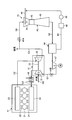
- FIG. 1 is a schematic diagram showing a diesel engine equipped with an EGR system to which the demister unit of the first embodiment is applied.
- FIG. 2 is a schematic configuration diagram illustrating the EGR system according to the first embodiment.
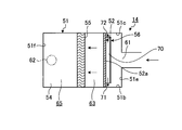
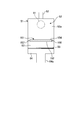
- FIG. 3 is a longitudinal sectional view showing the demister unit of the first embodiment. 4 is a cross-sectional view taken along the line IV-IV in FIG. 3 showing a horizontal cross section of the demister unit.
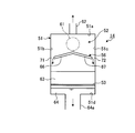
- FIG. 5 is a cross-sectional view taken along the line VV in FIG. 3 showing the inlet portion of the demister unit.
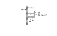
- FIG. 6 is a cross-sectional view showing a receiving flow path.
- FIG. 7A is a cross-sectional view illustrating a modified example of the receiving channel.
- FIG. 7A is a cross-sectional view illustrating a modified example of the receiving channel.
- FIG. 7-2 is a cross-sectional view illustrating a modified example of the receiving channel.
- FIG. 7C is a cross-sectional view illustrating a modification of the receiving channel.
- FIG. 7D is a cross-sectional view illustrating a modified example of the receiving channel.
- FIG. 8 is a longitudinal sectional view showing a modification of the demister unit of the first embodiment.
- FIG. 9 is a longitudinal sectional view showing a modification of the demister unit of the first embodiment.
- FIG. 10 is a longitudinal sectional view showing an inlet portion of the demister unit of the second embodiment.
- FIG. 11 is a cross-sectional view illustrating a receiving flow path.
- FIG. 12 is a longitudinal sectional view illustrating a modification of the demister unit of the second embodiment.
- FIG. 13 is a longitudinal sectional view showing an inlet portion of the demister unit of the third embodiment.
- FIG. 14 is a longitudinal sectional view showing the demister unit of the fourth embodiment.
- FIG. 15 is a longitudinal sectional view showing an inlet portion of the demister unit.
- FIG. 1 is a schematic diagram showing a diesel engine equipped with an EGR system to which the demister unit of the first embodiment is applied
- FIG. 2 is a schematic configuration diagram showing the EGR system of the first embodiment.
- the marine diesel engine 10 includes an engine body 11, a supercharger 12, and an EGR system 13.
- the engine body 11 is a propulsion engine (main engine) that drives and rotates the propeller for propulsion via a propeller shaft, although not shown.
- This engine body 11 is a uniflow scavenging exhaust type diesel engine, which is a two-stroke diesel engine, in which the flow of intake and exhaust in the cylinder is unidirectional from the bottom to the top so as to eliminate the residual exhaust. It is.
- the engine body 11 includes a plurality of cylinders (combustion chambers) 21 in which pistons move up and down, a scavenging trunk 22 that communicates with each cylinder 21, and an exhaust manifold 23 that communicates with each cylinder 21.
- a scavenging port 24 is provided between each cylinder 21 and the scavenging trunk 22, and an exhaust passage 25 is provided between each cylinder 21 and the exhaust manifold 23.
- the supply line G ⁇ b> 1 is connected to the scavenging trunk 22, and the exhaust line G ⁇ b> 2 is connected to the exhaust port 23.
- the supercharger 12 is configured by connecting a compressor 31 and a turbine 32 so as to rotate integrally with a rotary shaft 33.
- the turbine 32 is rotated by the exhaust gas discharged from the exhaust line G2 of the engine body 11, the rotation of the turbine 32 is transmitted by the rotary shaft 33, and the compressor 31 is rotated. / Or the recirculated gas is compressed and supplied to the engine body 11 from the supply air line G1.
- the compressor 31 is connected to a suction line G6 that sucks air from the outside (atmosphere).
- the supercharger 12 is connected to an exhaust line G3 that discharges exhaust gas that has rotated the turbine 32.
- the exhaust line G3 is connected to a chimney (funnel) (not shown).
- An EGR system 13 is provided between the exhaust line G3 and the air supply line G1.
- the EGR system 13 includes exhaust gas recirculation lines G4, G5, and G7, a scrubber 42, a demister unit 14, and an EGR blower (blower) 47.
- This EGR system 13 mixes a part of the exhaust gas discharged from the marine diesel engine 10 with air, and then compresses it by a supercharger and recirculates it to the marine diesel engine 10 as a combustion gas, so that NOx due to combustion is obtained. Is suppressed.
- a part of the exhaust gas is extracted from the downstream side of the turbine 32, but a part of the exhaust gas may be extracted from the upstream side of the turbine 32.
- the exhaust gas recirculation line G4 has one end connected to the middle part of the exhaust line G3.
- the exhaust gas recirculation line G4 is provided with an EGR inlet valve (open / close valve) 41A, and the other end is connected to the scrubber 42.
- the EGR inlet valve 41A opens and closes the exhaust gas recirculation line G4 to turn ON / OFF the exhaust gas that is diverted from the exhaust line G3 to the exhaust gas recirculation line G4.
- the EGR inlet valve may be a flow rate adjustment valve to adjust the flow rate of exhaust gas passing through the exhaust gas recirculation line G4.
- the scrubber 42 is a venturi-type scrubber, and includes a hollow throat portion 43, a venturi portion 44 into which exhaust gas is introduced, and an enlarged portion 45 that gradually returns to the original flow velocity.
- the scrubber 42 includes a water injection unit 46 that injects water to the exhaust gas introduced into the venturi unit 44.
- the scrubber 42 is connected to an exhaust gas recirculation line G5 for discharging exhaust gas from which harmful substances such as particulate matter (PM) such as SOx and dust are removed and waste water containing the harmful substances.
- the venturi type is employ
- the exhaust gas recirculation line G5 is provided with a demister unit 14 and an EGR blower 47.
- the demister unit 14 separates exhaust gas from which harmful substances have been removed by water jet and waste water.
- the demister unit 14 is provided with a drainage circulation line W ⁇ b> 1 that circulates drainage to the water injection unit 46 of the scrubber 42.
- the drainage circulation line W1 is provided with a hold tank 49 and a pump 50 for temporarily storing drainage.
- the EGR blower 47 guides the exhaust gas in the scrubber 42 from the exhaust gas recirculation line G5 to the demister unit 14.
- the exhaust gas recirculation line G7 has one end connected to the EGR blower 47 and the other end connected to the compressor 31 via a mixer (not shown).
- the exhaust gas is sent to the compressor 31 by the EGR blower 47.
- the exhaust gas recirculation line G7 is provided with an EGR outlet valve (open / close valve or flow rate adjusting valve) 41B. Air from the suction line G6 and exhaust gas (recirculation gas) from the exhaust gas recirculation line G7 are mixed in a mixer to generate combustion gas.
- This mixer may be provided separately from the silencer, or the silencer may be configured to add a function of mixing exhaust gas and air without separately providing a mixer.
- the supercharger 12 can supply the combustion gas compressed by the compressor 31 from the supply line G1 to the engine main body 11, and an air cooler (cooler) 48 is provided in the supply line G1.
- the air cooler 48 cools the combustion gas by exchanging heat between the combustion gas compressed by the compressor 31 and having a high temperature and the cooling water.
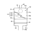
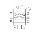
- the demister unit 14 described above includes a casing 51, a baffle plate 52, a porous plate 53, a demister support plate 54, a demister main body 55, and a receiving member 56. Yes.
- the casing 51 has a hollow rectangular shape and is configured as a container that forms an internal space. That is, the casing 51 is formed in a box shape by the ceiling 51a, the left and right side walls 51b and 51c, the bottom 51d, the upstream side wall 51e, and the downstream side wall 51f.
- the casing 51 is formed with an inlet 61 into which exhaust gas and drainage are introduced on the upper side of one end (right end in FIG. 3), and on the upper side on the other end (left end in FIG. 3) side.
- An outlet 62 for discharging exhaust gas (fluid) is formed.
- the casing 51 is provided on the exhaust gas recirculation line G5.
- the baffle plate 52 is disposed along the vertical direction in the casing 51 so as to face the inlet portion 61, thereby forming an upstream flow path 63 as a bent flow path.
- the baffle plate 52 is formed of a flat plate through which exhaust gas and liquid droplets cannot pass, and the upper end portion is fixed in close contact with the ceiling portion 51a of the casing 51, and the left and right side portions are the left and right side wall portions of the casing 51.
- 51b and 51c are closely_contact
- the distance from the inlet 61 in the casing 51 to the flat portion 52a of the baffle plate 52 is set to be equal to or smaller than the inner diameter of the inlet 61. Therefore, the exhaust gas introduced into the casing 51 from the inlet 61 flows into the upstream flow path 63 after colliding with the baffle plate. That is, the exhaust gas introduced into the casing 51 from the inlet portion 61 flows downward in the vertical direction by the baffle plate, and then bends and flows in the horizontal direction. Further, the flow path area below the baffle plate 52 is set to be larger than the flow path area when introduced into the casing 51 from the inlet 61. Therefore, when the exhaust gas introduced into the casing 51 from the inlet portion 61 flows below the baffle plate 52, it is not accelerated again.
- the perforated plate 53 is fixed horizontally in the lower part in the casing 51.
- the perforated plate 53 is formed of a flat plate in which a large number of through holes (not shown) are formed so that exhaust gas and droplets can pass through.
- the perforated plate 53 is horizontally arranged at a position above the bottom 51d of the casing 51 by a predetermined height, and the outer peripheral portion is fixed in close contact with the side wall portions 51b and 51c and the front and rear wall portions 51e and 51f of the casing 51.
- a reservoir 64 is formed between the perforated plate 53 and the bottom 51d.
- the storage part 64 is provided with the drain flow path 64a in the lower part.
- the demister support plate 54 is disposed horizontally at the outlet 62 from the baffle plate 52 and above the perforated plate 53 by a predetermined height.
- the demister support plate 54 is formed of a flat plate through which exhaust gas and droplets cannot pass, one end of which is closely attached to the rear wall portion 51f of the casing 51, and the left and right sides are the left and right sides of the casing 51.
- the side wall portions 51b and 51c are fixed in close contact with each other, the other end portion is separated from the baffle plate 52 by a predetermined distance, and the upstream flow path 63 is provided here.
- the lower end of the baffle plate 52 is located below the lower surface of the demister support plate 54 in the vertical direction.
- the demister body 55 is disposed in the casing 51 on the downstream side in the flow direction of the exhaust gas from the upstream channel 63 to remove mist from the exhaust gas.
- the demister main body 55 is provided with a flow path bent a plurality of times so that exhaust gas can pass inside, and is configured as a plate-like body as a whole along the vertical direction.
- the demister main body 55 is installed on the other end of the demister support plate 54, the upper end is in close contact with the ceiling 51 a of the casing 51, and the left and right sides are in close contact with the left and right side walls 51 b and 51 c of the casing 51. is doing.
- the demister body 55 is disposed so as to face the baffle plate 52, and the upstream side of the demister body 55 is an upstream channel 63, and the downstream side of the demister body 55 is a downstream channel 65. That is, the upstream flow path 63 is configured to be separated by the front wall portion 51e of the casing 51, the side wall portions 51b and 51c, the baffle plate 52, the porous plate 53, and the lower surface of the demister support plate 54.
- the side wall portions 51b and 51c of the casing 51, the rear wall portion 51f and the upper surface of the demister support plate 54 are separated. Therefore, the exhaust gas introduced into the casing 51 from the inlet portion 61 reaches the demister body 55 through the upstream channel 63, passes through the demister body 55, and then passes through the downstream channel 65 from the outlet portion 62. Discharged.
- the receiving member 56 receives droplets generated when the exhaust gas introduced into the casing 51 from the inlet 61 collides with the baffle plate 52.
- the receiving member 56 is provided on the flat surface portion 52 a facing the inlet portion 61 in the baffle plate 52.
- the receiving member 56 is provided on the flat portion 52 a of the baffle plate 52 so as to be positioned below the inlet portion 61 in the vertical direction.
- the receiving member 56 is provided on the flat surface portion 52a of the baffle plate 52 along the left-right direction, and includes two receiving member main bodies 66 and 67.
- the receiving member main body 66 extends from an intermediate position in the horizontal direction of the flat portion 52a of the baffle plate 52 toward the one side wall portion 51b, and the receiving member main body 67 extends in the horizontal direction of the flat portion 52a of the baffle plate 52. Is extended from the intermediate position toward the other side wall 51c.
- Each of the receiving member main bodies 66 and 67 is provided to be inclined downward toward the side wall portions 51 b and 51 c of the casing 51.
- the receiving member 56 (receiving member main bodies 66 and 67) includes a bottom portion 68 and a side portion 69 provided along the flow direction of the liquid droplets.
- the bottom portion 68 is fixed in close contact with each other so that one side portion is orthogonal to the flat portion 52 a of the baffle plate 52, and the side portion 69 is vertical so that the lower end portion is orthogonal to the other side portion of the bottom portion 68. It is closely attached and fixed.
- the receiving member 56 (the receiving member main bodies 66 and 67) is a receiving member extending in the left-right direction in the baffle plate 52 by forming a U-shaped cross section by the flat portion 52a, the bottom portion 68, and the side portion 69 of the baffle plate 52.
- a flow path 70 is formed.
- the exhaust gas introduced into the casing 51 from the inlet portion 61 collides with the baffle plate 52 to generate liquid droplets, and the liquid droplets flow downward through the flat portion 52a of the baffle plate 52.
- the receiving member 56 can receive the droplet in the receiving flow path 70.
- drainage channels 71 and 72 are provided for flowing the droplets received by the receiving channel 70 of the receiving member 56 to the storage part 64 of the casing 51.
- the receiving member main bodies 66 and 67 are extended from the center position in the left-right direction at the inlet portion 61 toward the left and right side wall portions 51b and 51c, and a gap is provided between the distal end portion and the left and right side wall portions 51b and 51c.
- the drainage channels 71 and 72 are provided here. Therefore, the liquid droplets received by the receiving flow path 70 of the receiving member 56 flow downward in the inclination direction of the receiving flow path 70, and thus can flow from the drainage flow paths 71 and 72 to the storage portion 64.
- a hanging plate 57 is provided below the demister body 55.
- the hanging plate 57 is formed of a flat plate through which exhaust gas and droplets cannot pass, and its upper end is fixed in close contact with the lower surface of the demister support plate 54 so as to hang from the lower surface of the demister support plate 54.
- the hanging plate 57 is arranged so that the flat portion thereof is flush with the end portion of the demister support plate 54 without any step.
- the lower end of the hanging plate 57 is located at the same position as the lower end of the baffle plate 52 in the vertical direction or upward in the vertical direction. Therefore, the exhaust gas flowing through the upstream flow path 53 is guided from the lower region of the demister support plate 54 toward the upstream surface of the demister body 55 by the hanging plate 57.
- the receiving member 56 (receiving member main bodies 66 and 67) has the receiving flow path 70 having a U-shaped cross section formed by the flat portion 52a, the bottom portion 68, and the side portion 69 of the baffle plate 52.
- the present invention is not limited to this configuration.
- 7A to 7D are cross-sectional views illustrating modifications of the receiving flow channel.
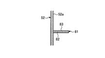
- the receiving member 81 includes a bottom portion 82 provided along the flow direction of the droplet.
- the bottom portion 82 is fixed in close contact with each other horizontally so that one side portion thereof is orthogonal to the flat portion 52a of the baffle plate 52. Therefore, in the receiving member 81, a receiving flow path 83 along the left-right direction of the baffle plate 52 is formed by the flat portion 52 a and the bottom portion 82 of the baffle plate 52.
- the receiving member 84 is constituted by a bottom portion 85 provided along the flow direction of the droplet.
- the bottom 85 has one side fixed to the flat surface 52a of the baffle plate 52 and the other end inclined upward from the horizontal, and the angle between the flat 52a and the upper surface of the bottom 85 is a predetermined angle ( (Acute angle). Therefore, in the receiving member 84, a receiving flow path 86 along the left-right direction of the baffle plate 52 is formed by the flat portion 52 a and the bottom portion 85 of the baffle plate 52.
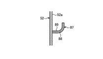
- the receiving member 87 is constituted by a curved bottom portion 88 provided along the flow direction of the droplet.
- the curved bottom portion 88 is fixed in close contact so that one side thereof is orthogonal to the flat portion 52a of the baffle plate 52, and extends so that the other side is curved upward. Therefore, in the receiving member 87, a receiving flow path 89 along the left-right direction of the baffle plate 52 is formed by the flat portion 52 a and the curved bottom portion 88 of the baffle plate 52.
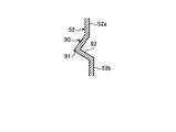
- the receiving member 90 is constituted by a recess 91 provided along the flow direction of the droplet.
- the recess 91 is formed by bending the baffle plate 52, and the recess 91 forms a receiving flow path 92 along the left-right direction of the baffle plate 52.
- the receiving member 56 includes two receiving member main bodies 66 and 67, and the receiving member main bodies 66 and 67 are directed downward toward the side wall portions 51 b and 51 c of the casing 51. Although inclined, it is not limited to this configuration. 8 and 9 are longitudinal sectional views showing modifications of the demister unit of the first embodiment.
- the receiving member 101 receives droplets generated by the exhaust gas introduced into the casing 51 from the inlet portion 61 colliding with the baffle plate 52.
- the receiving member 101 is provided on a flat surface portion 52 a facing the inlet portion 61 in the baffle plate 52.
- the receiving member 101 is provided on the flat surface portion 52 a of the baffle plate 52 so as to be positioned below the inlet portion 61 in the vertical direction.
- the receiving member 101 is provided on the flat surface portion 52a of the baffle plate 52 along the left-right direction, extends from one side wall portion 51b of the casing 51 toward the other side wall portion 51c, and the other side wall portion 51c. It inclines below and is provided.
- a drainage channel 102 is provided for flowing the droplet received by the receiving member 101 to the storage portion 64 of the casing 51.
- One end of the receiving member 101 is in close contact with the side wall 51b of the casing 51, but a gap is provided between the other end and the side wall 51c, and the drainage channel 102 is provided here.
- the receiving member 101 can receive this droplet. Further, since the liquid droplet received by the receiving member 101 flows downward in the inclination direction of the receiving member 101, it can flow from the drainage flow channel 102 to the storage portion 64.
- the receiving member 111 receives droplets generated when the exhaust gas introduced into the casing 51 from the inlet 61 collides with the baffle plate 52.
- the receiving member 111 is provided on the flat surface portion 52 a facing the inlet portion 61 in the baffle plate 52.
- the receiving member 111 is provided on the flat surface portion 52 a of the baffle plate 52 so as to be positioned below the inlet portion 61 in the vertical direction.
- the receiving member 111 includes three receiving member main bodies 112, 113, and 114, and is provided on the flat portion 52 a of the baffle plate 52 along the left-right direction.
- Each of the receiving member main bodies 112, 113, 114 is arranged in the left-right direction (horizontal direction) of the baffle plate 52 and at a predetermined interval in the vertical direction, and a part thereof overlaps in the vertical direction.
- Each receiving member main body 112, 113, 114 is provided to be inclined downward from one side wall 51 b of the casing 51 toward the other side wall 51 c.
- a drainage channel 115 is provided for flowing the droplet received by the receiving member 111 to the storage portion 64 of the casing 51.
- one end of the receiving member main body 112 is in close contact with the side wall 51b of the casing 51, but a gap is provided between the other end of the receiving member main body 114 and the side wall 51c.
- a drainage channel 115 is provided here.
- the receiving member 111 can receive the droplet. That is, the liquid droplets that flow down along the flat surface portion 52 a of the baffle plate 52 are received by the receiving member main bodies 112, 113, 114 and flow in order, and can flow from the drainage flow path 115 to the storage portion 64.
- combustion air is supplied from the scavenging trunk 22 into the cylinder 21, the combustion air is compressed by the piston, and fuel is injected into the high-temperature air to spontaneously ignite and burn the engine body 11. To do.
- the generated combustion gas is discharged as exhaust gas from the exhaust manifold 23 to the exhaust line G2.
- the exhaust gas discharged from the engine body 11 is discharged to the exhaust line G3 after rotating the turbine 32 in the supercharger 12, and when the EGR inlet valve 41A is closed, the entire amount is discharged to the outside from the exhaust line G3. Is done.
- the scrubber 42 removes harmful substances such as SOx and dust contained in the exhaust gas flowing into the exhaust gas recirculation line G4. That is, when the exhaust gas passes through the venturi unit 44 at a high speed, the scrubber 42 cools the exhaust gas with this water by injecting water from the water injection unit 46 and also removes particulates (PM) such as SOx and dust. Drop it together and remove it. And the water containing SOx, dust, etc. flows into the demister unit 14 with EGR gas.
- PM particulates
- the exhaust gas from which harmful substances have been removed by the scrubber 42 is discharged to the gas discharge line G5, and after the scrubber washing water is separated by the demister unit 14, it is sent to the supercharger 12 by the exhaust gas supply line G7.
- the exhaust gas is mixed with the air sucked from the suction line G6 to become a combustion gas, compressed by the compressor 31 of the supercharger 12, and then cooled by the air cooler 48, from the air supply line G1 to the engine body 11. To be supplied.
- the exhaust gas introduced into the casing 51 from the inlet portion 61 collides with the flat portion 52 a of the baffle plate 52 on the front, and thus along the flat portion 52 a of the baffle plate 52.
- the mist that spreads out becomes droplets and adheres to the flat portion 52a of the baffle plate 52.
- the droplets adhering to the flat surface portion 52 a of the baffle plate 52 flow down downward along the flat surface portion 52 a by their own weight and are received by the receiving member 56.
- the liquid droplets received by the receiving member 56 are collected in the receiving flow path 70 and flow toward the side surfaces 51b and 51c of the casing 51 due to the inclination of the receiving member main bodies 66 and 67. And the droplet which flowed to each side part 51b, 51c of the casing 51 is drained by the storage part 64 through each drainage flow path 71,72, and is discharged
- the exhaust gas from which a part of the mist has been removed becomes a downward flow by the flat surface portion 52a of the baffle plate 52 and the ceiling portion 51a, the side wall portions 51b and 51b, and the front wall portion 51e of the casing 51, Flows in.
- the exhaust gas that has flowed into the upstream flow path 63 becomes a horizontal flow by the perforated plate 53 and flows upward by the hanging plate 57 and reaches the demister body 55.
- the exhaust gas flowing through the upstream channel 63 passes below the baffle plate 52, but the droplets adhering to the baffle plate 52 are received by the receiving member 56 and drainage channels 71, 72.
- the water Since the water is drained to the storage portion 64, it does not fall into the upstream flow path 63. For this reason, the exhaust gas flowing through the upstream flow path 63 is suppressed from contacting with water, but the re-uptake of the mist removed from the exhaust gas into the exhaust gas is suppressed. Further, the exhaust gas flows through the bent upstream flow path 63, so that mist is removed by centrifugal force. Further, when the exhaust gas passes through the demister main body 55, the remaining mist aggregates into droplets and falls into the storage portion 64. Thereafter, the exhaust gas from which the mist has been removed is discharged from the outlet 62 through the downstream flow path 65.
- the casing 51 having a hollow shape and having the exhaust gas inlet portion 61 and the outlet portion 62 is disposed opposite to the inlet portion 61 in the casing 51.
- a receiving member 56 is provided for receiving droplets generated by the collision of exhaust gas with 52.
- the mist removal efficiency can be improved.
- the receiving member 56 is provided with a receiving flow path 70 along the left-right direction of the baffle plate 52. Accordingly, the liquid droplets adhering to the baffle plate 52 flow down the flat portion 52a of the baffle plate 52 due to their own weight and are received by the receiving flow path 70. Can be collected in a place.
- a bottom 68 and a side 69 are provided as the receiving flow path 56 along the flow direction of the droplet. Therefore, a large amount of liquid droplets can be properly received without overflowing from the receiving flow path 70.
- the receiving flow path 70 is inclined downward toward the side wall portions 51 b and 51 c of the casing 51. Therefore, the received liquid droplet can be appropriately discharged and discharged to the side wall portions 51b and 51c of the casing 51 along the inclination direction of the receiving flow path 70.
- the receiving member 56 is provided on the flat surface portion 52 a facing the inlet portion 61 in the baffle plate 52. Therefore, the droplet generated by colliding with the flat surface portion 52 a of the baffle plate 52 can be properly received by the receiving member 56.
- drainage channels 71 and 72 are provided to allow the droplets received by the receiving channel 70 to flow to the storage part 64 at the bottom of the casing 51. Therefore, the droplets adhering to the baffle plate 52 flow down the flat portion 52a of the baffle plate 52 due to their own weight, and are received by the receiving channel 70, and the droplets received by the receiving channel 70 are the drain channels 71, 72 flows into the storage portion 64, and the contact with the exhaust gas flowing through the upstream flow path 63 by properly draining the droplets can be suppressed.
- the drain channels 71 and 72 are provided between the end of the receiving channel 70 and the side walls 51b and 51c of the casing 51. Accordingly, by draining the droplets along the side wall portions 51b and 51c of the casing 51, the contact between the generated droplets and the exhaust gas flowing through the upstream channel 63 can be suppressed, and the structure is simplified. can do.
- the exhaust gas recirculation line G4 that recirculates a part of the exhaust gas discharged from the engine body 11 as a part of the combustion gas to the engine body, and the exhaust gas recirculation line.
- a scrubber 42 that removes harmful substances by injecting water into the exhaust gas flowing through G4 and a demister unit 14 into which the exhaust gas discharged from the scrubber 42 is introduced are provided.
- the droplet generated by the exhaust gas colliding with the baffle plate 52 in the demister unit 14 flows down the flat portion 52a of the baffle plate 52 by its own weight and is received by the receiving member 56.
- the exhaust gas flowing through the path 63 does not take in the droplets again as mist, and the mist removed from the exhaust gas is prevented from being taken into the exhaust gas again. As a result, the mist removal efficiency can be improved.
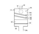
- FIG. 10 is a longitudinal sectional view showing an inlet portion of the demister unit of the second embodiment
- FIG. 11 is a sectional view showing a receiving flow path
- FIG. 12 is a longitudinal section showing a modification of the demister unit of the second embodiment.
- symbol is attached
- the demister unit 120 includes a casing 51, a baffle plate 52, a perforated plate 53, a demister support plate 54, a demister body 55, and a plurality of receiving members 121. , 122. Since the casing 51, the baffle plate 52, the porous plate 53, the demister support plate 54, and the demister main body 55 have the same configuration as in the first embodiment, the description thereof is omitted.
- the receiving passages 121 and 122 are provided in parallel (two in this embodiment) in parallel in the vertical direction.
- Each of the receiving members 121 and 122 receives droplets generated by the exhaust gas introduced into the casing 51 from the inlet portion 61 colliding with the baffle plate 52.
- the receiving members 121 and 122 are flat portions 52 a that face the inlet portion 61 in the baffle plate 52, and are provided below the inlet portion 61 in the vertical direction.
- Each of the receiving members 121 and 122 has substantially the same configuration as the receiving member 56 (see FIG. 5) of the first embodiment, and is directed from the center position in the left-right direction at the inlet portion 61 toward the side wall portions 51b and 51c. It is comprised from the receiving member main body 123, 124, 125, 126 which extends and inclines below. As shown in FIG. 11, the receiving members 121 and 122 (receiving member main bodies 123, 124, 125, and 126) are composed of a bottom portion and a side portion that are provided along the flow direction of the liquid droplets. Receiving flow paths 127 and 128 along the left-right direction in 52 are formed.
- the lower receiving member 122 is set to have a larger protruding amount from the flat portion 52 a of the baffle plate 52 than the upper receiving member 121. That is, the lower receiving member 122 protrudes more toward the inlet 61 than the upper receiving member 121. Further, as shown in FIG. 10, drainage channels 71 and 72 are provided for allowing the droplets received by the receiving channels 127 and 128 of the receiving members 121 and 122 to flow into the storage portion 64 of the casing 51.
- the droplets flow down through the flat portion 52 a of the baffle plate 52.
- the receiving members 121 and 122 can receive the liquid droplets in the receiving flow paths 127 and 128.
- the drainage channels 71 and 72 enter the storage portion 64. It can flow.
- the receiving members 121 and 122 are constituted by two receiving member main bodies 123, 124, 125, and 126, and the receiving member main bodies 123, 124, 125, and 126 are included in the casing 51. Although it shall incline below toward the side wall parts 51b and 51c, it is not limited to this structure.
- a plurality (two in this embodiment) of receiving channels 131 and 132 are provided in parallel in the vertical direction.
- Each of the receiving members 131 and 132 receives droplets generated by the exhaust gas introduced into the casing 51 from the inlet portion 61 colliding with the baffle plate 52.
- the receiving members 131 and 132 are flat portions 52 a that face the inlet portion 61 in the baffle plate 52, and are provided below the inlet portion 61 in the vertical direction.
- the receiving members 131 and 132 are provided on the flat surface portion 52a of the baffle plate 52 along the left-right direction, and extend from one side wall portion 51b to the other side wall portion 51c in the casing 51, and the other side wall Inclined downward toward the part 51c.
- a drainage flow path 102 is provided for allowing the droplets received by the receiving members 131 and 132 to flow to the storage portion 64 of the casing 51.
- the receiving members 131 and 132 can receive the liquid droplets. Then, since the droplets received by the receiving members 131 and 132 flow downward in the inclined direction, they can flow from the drainage flow path 102 to the storage portion 64.
- the protruding amounts of the upper receiving members 121 and 131 and the lower receiving members 122 and 132 from the flat portion 52a of the baffle plate 52 may be the same, or the lower side.
- the protruding amount of the receiving members 122 and 132 may be larger than the protruding amount of the upper receiving members 121 and 131.
- the number of receiving members is not limited to two and may be three or more.
- a plurality of receiving members 121 and 122 (131 and 132) for receiving droplets generated by the collision of the exhaust gas with the baffle plate 52 are provided in parallel in the vertical direction. ing.
- the droplet generated by the exhaust gas colliding with the baffle plate 52 flows down the flat portion 52a of the baffle plate 52 by its own weight and is received by the receiving members 121, 122 (131, 132), the upstream side The exhaust gas flowing through the flow path 63 does not take in the droplets again as mist, and the re-uptake of the mist removed from the exhaust gas into the exhaust gas can be suppressed. As a result, the mist removal efficiency can be improved. Further, by providing a plurality of receiving members 121, 122 (131, 132) in parallel in the vertical direction, it is possible to reliably receive the droplets generated by the exhaust gas colliding with the flat portion 52a of the baffle plate 52. .
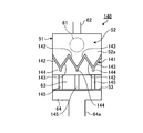
- FIG. 13 is a longitudinal sectional view showing an inlet portion of the demister unit of the third embodiment.
- symbol is attached
- the demister unit 140 includes a casing 51, a baffle plate 52, a porous plate 53, a demister support plate 54, a demister body 55, and a receiving member 141. I have. Since the casing 51, the baffle plate 52, the porous plate 53, the demister support plate 54, and the demister main body 55 have the same configuration as in the first embodiment, the description thereof is omitted.
- the receiving flow path 141 receives the droplets generated by the exhaust gas introduced into the casing 51 from the inlet portion 61 colliding with the baffle plate 52.
- the receiving member 141 is a flat portion 52 a that faces the inlet portion 61 in the baffle plate 52, and is provided below the inlet portion 61 in the vertical direction.
- Each receiving member 141 includes a plurality of receiving member main bodies 142 and 143 that are inclined so as to form a V shape. And the water collection part 144 is provided in the lower connection part of each receiving member main body 142,143. That is, each of the receiving member main bodies 142 and 143 is provided with a receiving flow path (not shown), and this receiving flow path is opened at the position of the water collecting portion 144. Further, below the water collecting part 144 of the receiving member 141, a piping part 145 is provided as a drainage channel for flowing the received liquid droplets to the storage part 64 of the casing 51.
- the droplets flow down through the flat portion 52 a of the baffle plate 52.
- the receiving member 141 allows each receiving member main body 142, 143 to receive this droplet.
- the liquid droplets received by the receiving member main bodies 142 and 143 of the receiving member 141 flow downward in the inclined direction and are combined with the water collecting portions 144, and from the water collecting portions 144 to the piping portions 145. It can flow to the storage part 64 through.
- the receiving member 141 for receiving the droplet generated by the collision of the exhaust gas with the baffle plate 52 is provided, and the droplet received by the receiving channel 141 is received.
- a piping part 145 is provided as a drainage channel that flows from the water collecting part 135 to the storage part 64 below the casing 51.
- the droplets adhering to the baffle plate 52 flow down the flat portion 52a of the baffle plate 52 due to their own weight and are received by the receiving member 141, and the droplets received by the receiving member 141 are transferred from the water collecting portion 144 to the piping portion. It flows to the storage part 64 through 145, and it is possible to prevent the liquid droplets from being properly drained and contact with the exhaust gas flowing through the upstream flow path 63.
- the droplets received by the receiving member 141 in the drainage channel are used as the piping unit 145 that communicates from the water collection unit 144 to the storage unit 64, so that the generated droplets are caused to flow to the storage unit 64 by the piping unit 145. The contact between the generated droplet and the exhaust gas flowing through the upstream flow path 63 can be prevented.
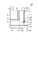
- FIG. 14 is a longitudinal sectional view showing a demister unit of the fourth embodiment
- FIG. 15 is a longitudinal sectional view showing an inlet portion of the demister unit.
- symbol is attached
- the demister unit 150 includes a casing 51, a baffle plate 52, a porous plate 53, a demister support plate 54, a demister body 55, and a receiving member. 151. Since the casing 51, the baffle plate 52, the porous plate 53, the demister support plate 54, and the demister main body 55 have the same configuration as in the first embodiment, the description thereof is omitted.
- the receiving flow channel 151 receives a droplet generated when the exhaust gas introduced into the casing 51 from the inlet 61 collides with the baffle plate 52.
- the receiving member 151 is provided in the lower part of the baffle plate 52 in the vertical direction.
- Each receiving member 151 includes a bottom portion 152 and both side portions 153 and 154 provided along the flow direction of the droplet.
- the bottom portion 152 is disposed horizontally below the baffle plate 52 so as to be orthogonal to the flat surface portion 52 a, and the both side portions 153, 154 are formed vertically so that the lower end portions are orthogonal to the respective side portions of the bottom portion 152. Closely fixed. Therefore, in the receiving member 151, a receiving flow path 155 that forms a U-shaped cross section and extends in the left-right direction in the baffle plate 52 is formed by the bottom portion 152 and both side portions 153 and 154.
- the receiving member 151 will be arrange
- the droplets flow down through the flat portion 52 a of the baffle plate 52.
- the receiving member 151 can receive the liquid droplet in which the receiving flow path 155 flows from the lower end portion of the baffle plate 52. Then, the droplets received by the receiving channel 155 of the receiving member 151 can flow from the drain channels 157 and 158 to the storage unit 64.
- the receiving member 151 for receiving the liquid droplets generated by the collision of the exhaust gas with the baffle plate 52 is provided in the lower portion of the baffle plate 52 in the vertical direction.
- the liquid droplets generated by the exhaust gas colliding with the baffle plate 52 flow down the flat portion 52a of the baffle plate 52 due to their own weight and are received by the receiving member 151, so that the exhaust gas flowing through the upstream flow path 63 flows.
- the droplets are not taken in again as mist, and the mist removed from the exhaust gas is prevented from being taken into the exhaust gas again.
- the mist removal efficiency can be improved.
- the receiving member 151 is provided below the baffle plate 52, the droplets can be received effectively.
- the receiving member in the first to third embodiments, is inclined, and in the fourth embodiment, the receiving member is horizontal, but the receiving member of the present invention is horizontal. Any of inclination may be sufficient and you may make it incline partially.
- the shape of the casing 51 and the positions of the inlet portion 61 and the outlet portion 62 are not limited to the embodiments, and any one may be used as long as the inlet portion 61 and the baffle plate 52 face each other. It may be the position. Moreover, although the baffle plate 52 is arranged along the vertical direction, it may be inclined.
- the main engine is used as the marine diesel engine.
- the marine diesel engine can be applied to a diesel engine used as a generator.
Abstract
Provided are a demister unit and an EGR system. The present invention is provided with: a casing (51) formed in a hollow shape and having an inlet part (61) and an outlet part (62) for an exhaust gas; a baffle plate (52) disposed to face the inlet part (61) inside the casing (51) thereby forming a bent upstream-side flow passage (63); a demister main body (55) disposed further on the downstream side of the flow direction of the exhaust gas than the upstream-side flow passage (63) inside the casing (51), and removing mist from the exhaust gas; and a receiving member (56) for receiving droplets produced by the exhaust gas colliding with the baffle plate (52), whereby the repeated intake of the mist removed from the fluid back into the fluid is suppressed and mist removal efficiency is improved.
Description
本発明は、排ガスからミストを除去するデミスタユニット、このデミスタユニットが適用されるEGRシステムに関するものである。
The present invention relates to a demister unit that removes mist from exhaust gas, and an EGR system to which the demister unit is applied.
湿式排ガス処理装置を介してボイラから排出される排ガスは、ミストを含んでいることから、この排ガスに含まれるミストを除去する必要がある。排ガスに含まれるミストを除去するものとして、デミスタやミストエリミネータがあり、例えば、下記特許文献1に記載されている。この特許文献1に記載された湿式排ガス処理装置は、ボイラからの排ガスを入口煙道により除塵塔に導入し、ここで排ガス中の煤塵を除去した後、排ガスが除塵塔デミスタを通過するときに排ガス中のミストを除去するものである。
Since the exhaust gas discharged from the boiler via the wet exhaust gas treatment device contains mist, it is necessary to remove the mist contained in the exhaust gas. There exist a demister and a mist eliminator as what removes mist contained in exhaust gas, for example, it is indicated in the following patent documents 1. The wet exhaust gas treatment apparatus described in Patent Document 1 introduces exhaust gas from a boiler into a dust removal tower through an inlet flue, and after removing dust in the exhaust gas, the exhaust gas passes through the dust removal tower demister. It removes mist in the exhaust gas.
また、排ガス中のNOxを低減するものとしては、排ガス再循環(EGR)がある。このEGRは、内燃機関の燃焼室から排出された排ガスの一部を、燃焼用気体として燃焼室に戻すものである。そのため、燃焼用気体は、酸素濃度が低下し、燃料と酸素との反応である燃焼の速度を遅らせることで燃焼温度が低下し、NOxの発生量を減少させることができる。
Further, exhaust gas recirculation (EGR) is available to reduce NOx in exhaust gas. This EGR returns a part of the exhaust gas discharged from the combustion chamber of the internal combustion engine to the combustion chamber as a combustion gas. Therefore, the combustion gas has a reduced oxygen concentration, and the combustion temperature is lowered by delaying the combustion speed, which is a reaction between the fuel and oxygen, and the amount of NOx generated can be reduced.
上述したデミスタにて、入口から導入された排ガスを邪魔板に衝突させることで、排ガスに含まれるミストを除去するものがある。このとき、排ガスは、邪魔板に衝突することでミストが除去された後、この邪魔板の下方を通過する。一方、排ガスに含まれるミストは、邪魔板に衝突することで液滴となり、この邪魔板を伝って下方に落下する。そのため、ミストが除去された排ガスが邪魔板の下方を通過するとき、排ガスが邪魔板を伝って落下する液滴を巻き込むこととなり、排ガスは、再びミストを取り込んでしまい、含有するミスト量が増加してしまうという問題がある。
Some demisters remove the mist contained in the exhaust gas by colliding the exhaust gas introduced from the entrance with the baffle plate. At this time, after the mist is removed by colliding with the baffle plate, the exhaust gas passes below the baffle plate. On the other hand, the mist contained in the exhaust gas becomes liquid droplets by colliding with the baffle plate, and falls down through the baffle plate. Therefore, when the exhaust gas from which the mist has been removed passes below the baffle plate, the exhaust gas entrains droplets that fall through the baffle plate, and the exhaust gas takes in the mist again, increasing the amount of mist contained There is a problem of end up.
本発明は上述した課題を解決するものであり、流体から除去したミストの流体への再度の取込みを抑制してミスト除去効率の向上を図るデミスタユニット及びEGRシステムを提供することを目的とする。
The present invention solves the above-described problems, and an object of the present invention is to provide a demister unit and an EGR system that improve the efficiency of mist removal by suppressing reuptake of the mist removed from the fluid into the fluid.
上記の目的を達成するための本発明のデミスタユニットは、中空形状をなして流体の入口部と出口部を有するケーシングと、前記ケーシング内で前記入口部に対向して配置されることで屈曲流路を形成する邪魔板と、前記ケーシング内で前記屈曲流路より流体の流動方向の下流側に配置されて流体からミストを除去するデミスタ本体と、前記邪魔板に流体が衝突することによって生じた液滴を受け止める受止部材と、を備えることを特徴とするものである。
In order to achieve the above object, a demister unit according to the present invention includes a casing having a hollow shape and having a fluid inlet portion and an outlet portion, and a bent flow by being disposed opposite to the inlet portion in the casing. A baffle plate that forms a path, a demister body that is disposed downstream of the bent flow path in the flow direction of the fluid in the casing and removes mist from the fluid, and a fluid collides with the baffle plate And a receiving member that receives the droplet.
従って、入口部からケーシング内に導入された流体は、邪魔板に衝突することで、含まれるミストが液滴となって邪魔板に付着する。邪魔板に付着した液滴は、自重により邪魔板の平面部を流れ落ち、受止部材に受け止められる。一方、ミストの一部が除去された流体は、屈曲流路を流れることで、遠心力により更にミストが除去され、最終的にデミスタ本体により残存するミストが除去される。ここで、流体が邪魔板に衝突することで生成された液滴は、自重により邪魔板の平面部を流れ落ちて受止部材に受け止められることから、屈曲流路を流れる流体が再び液滴をミストとして取り込むことはなく、流体から除去したミストの流体への再度の取込みを抑制してミスト除去効率の向上を図ることができる。
Therefore, the fluid introduced into the casing from the inlet portion collides with the baffle plate, and the contained mist forms droplets and adheres to the baffle plate. The liquid droplets adhering to the baffle plate flow down the flat part of the baffle plate by their own weight and are received by the receiving member. On the other hand, the fluid from which a part of the mist is removed flows through the bent flow path, so that the mist is further removed by the centrifugal force, and finally the remaining mist is removed by the demister body. Here, the droplet generated by the collision of the fluid with the baffle plate flows down the flat portion of the baffle plate due to its own weight and is received by the receiving member, so that the fluid flowing through the bent channel again mists the droplet. The mist removal efficiency can be improved by suppressing the re-uptake of the mist removed from the fluid into the fluid.
本発明のデミスタユニットでは、前記受止部材は、前記邪魔板における左右方向に沿う受止流路であることを特徴としている。
The demister unit according to the present invention is characterized in that the receiving member is a receiving flow path along a horizontal direction of the baffle plate.
従って、邪魔板に付着した液滴は、自重により邪魔板の平面部を流れ落ち、受止流路に受け止められることとなり、受け止めた液滴を受止流路により流して所定の個所に集めることができる。
Therefore, the liquid droplets adhering to the baffle plate flow down the flat part of the baffle plate by its own weight and are received by the receiving flow path, and the received liquid droplets flow through the receiving flow path and can be collected at a predetermined location. it can.
本発明のデミスタユニットでは、前記受止流路は、液滴の流れ方向に沿って設けられる底部と側部を備えることを特徴としている。
In the demister unit of the present invention, the receiving flow path includes a bottom portion and a side portion provided along the flow direction of the droplet.
従って、受止流路を底部と側部により構成することで、多量の液滴を受止流路から溢れさせることなく適正に受け止めることができる。
Therefore, by configuring the receiving channel with the bottom and side portions, a large amount of liquid droplets can be properly received without overflowing the receiving channel.
本発明のデミスタユニットでは、前記受止流路は、前記ケーシングの内壁面に向かって下方に傾斜して設けられることを特徴としている。
In the demister unit of the present invention, the receiving flow path is provided to be inclined downward toward the inner wall surface of the casing.
従って、受止流路がケーシングの内壁面に向かって下方に傾斜することで、受け止めた液滴を受止流路によりケーシングの内壁面側に適正に流して排出することができる。
Therefore, since the receiving flow path is inclined downward toward the inner wall surface of the casing, the received liquid droplet can be appropriately flowed and discharged to the inner wall surface side of the casing through the receiving flow path.
本発明のデミスタユニットでは、前記受止部材は、前記邪魔板における前記入口部に対向する平面部に設けられることを特徴としている。
The demister unit according to the present invention is characterized in that the receiving member is provided in a flat portion facing the inlet portion of the baffle plate.
従って、受止部材が邪魔板における入口部に対向する平面部に設けられることで、邪魔板の平面部に衝突して生成された液滴を受止部材により適正に受け止めることができる。
Therefore, by providing the receiving member on the flat portion facing the entrance portion of the baffle plate, it is possible to appropriately receive the droplet generated by colliding with the flat portion of the baffle plate by the receiving member.
本発明のデミスタユニットでは、前記受止部材は、前記邪魔板における鉛直方向の下部に設けられることを特徴としている。
The demister unit according to the present invention is characterized in that the receiving member is provided at a lower portion of the baffle plate in the vertical direction.
従って、受止部材が邪魔板における鉛直方向の下部に設けられることで、邪魔板の平面部に衝突して生成された液滴を邪魔板の下部で受止部材により効果的に受け止めることができる。
Therefore, by providing the receiving member at the lower portion of the baffle plate in the vertical direction, the droplet generated by colliding with the flat portion of the baffle plate can be effectively received by the receiving member at the lower portion of the baffle plate. .
本発明のデミスタユニットでは、前記受止部材は、鉛直方向に並列に複数設けられることを特徴としている。
The demister unit of the present invention is characterized in that a plurality of the receiving members are provided in parallel in the vertical direction.
従って、受止部材を鉛直方向に並列して複数設けることで、邪魔板の平面部に衝突して生成された液滴を確実に受け止めることができる。
Therefore, by providing a plurality of receiving members in parallel in the vertical direction, it is possible to reliably receive droplets generated by colliding with the flat portion of the baffle plate.
本発明のデミスタユニットでは、前記受止部材が受け止めた液滴を前記ケーシングの下部の貯留部に流す排水部材が設けられることを特徴としている。
The demister unit according to the present invention is characterized in that a drainage member is provided for allowing the droplet received by the receiving member to flow into a storage portion at the lower part of the casing.
従って、邪魔板に付着した液滴は、自重により邪魔板の平面部を流れ落ち、受止部材に受け止められ、受止部材が受け止めた液滴は、排水部材により貯留部に流れることとなり、液滴を適正に排水して屈曲部材を流れる流体との接触を防止することができる。
Therefore, the liquid droplets adhering to the baffle plate flow down the flat part of the baffle plate by its own weight and are received by the receiving member, and the liquid droplets received by the receiving member flow into the storage unit by the drainage member. Can be appropriately drained to prevent contact with the fluid flowing through the bending member.
本発明のデミスタユニットでは、前記排水流路は、前記受止部材の端部と前記ケーシングの内壁面との間に設けられることを特徴としている。
In the demister unit of the present invention, the drainage channel is provided between an end of the receiving member and an inner wall surface of the casing.
従って、排水流路をケーシングの内壁面の近傍に設けることで、生成された液滴と屈曲流路を流れる流体との接触を防止することができると共に、構造を簡素化することができる。
Therefore, by providing the drainage channel in the vicinity of the inner wall surface of the casing, it is possible to prevent contact between the generated droplet and the fluid flowing through the bent channel, and the structure can be simplified.
本発明のデミスタユニットでは、前記排水流路は、前記受止部材の集水部から前記貯留部に連通する配管部であることを特徴としている。
The demister unit according to the present invention is characterized in that the drainage flow path is a piping part communicating from the water collecting part of the receiving member to the storage part.
従って、排水流路を受止部材の集水部から貯留部に連通する配管部とすることで、生成された液滴を配管部により貯留部に流し、生成された液滴と屈曲流路を流れる流体との接触を防止することができる。
Therefore, by making the drainage channel a piping unit that communicates from the water collecting unit of the receiving member to the storage unit, the generated droplets are caused to flow to the storage unit by the piping unit, and the generated droplets and the bent channel are connected to each other. Contact with the flowing fluid can be prevented.
また、本発明のEGRシステムは、エンジンから排出された排ガスの一部を燃焼用気体の一部として前記エンジンに再循環する排ガス再循環ラインと、前記排ガス再循環ラインを流れる排ガスに対して水を噴射することで有害物質を除去するスクラバと、前記スクラバから排出された排ガスが導入される前記デミスタユニットと、を備えることを特徴とするものである。
Further, the EGR system of the present invention includes an exhaust gas recirculation line that recirculates a part of exhaust gas discharged from the engine as a part of combustion gas to the engine, and water for the exhaust gas flowing through the exhaust gas recirculation line. A scrubber that removes harmful substances by spraying and a demister unit into which exhaust gas discharged from the scrubber is introduced.
従って、エンジンから排出された排ガスは、その一部が排ガス再循環ラインを通るとき、スクラバによりこの排ガス再循環ラインを流れる排ガスに対して水が噴射されることで有害物質が除去され、デミスタユニットにより含有するミストが除去された後、エンジンに供給される。このとき、デミスタユニットでは、排ガスが邪魔板に衝突することで、含まれるミストが液滴となって邪魔板に付着し、この液滴が自重により邪魔板の平面部を流れ落ち、受止部材に受け止められる。そのため、屈曲流路を流れる流体が再び液滴をミストとして取り込むことはなく、流体から除去したミストの流体への再度の取込みを抑制してミスト除去効率の向上を図ることができる。
Therefore, when a part of the exhaust gas discharged from the engine passes through the exhaust gas recirculation line, harmful substances are removed by injecting water to the exhaust gas flowing through the exhaust gas recirculation line by the scrubber, and the demister unit After the mist contained therein is removed, it is supplied to the engine. At this time, in the demister unit, the exhaust gas collides with the baffle plate, so that the contained mist forms droplets and adheres to the baffle plate, and the droplets flow down the flat portion of the baffle plate by their own weight, and become a receiving member. It is accepted. Therefore, the fluid flowing in the bent flow path does not take in the droplets again as mist, and the mist removal efficiency can be improved by suppressing reuptake of the mist removed from the fluid into the fluid.
本発明のデミスタユニット及びEGRシステムによれば、流体から除去したミストの流体への再度の取込みを抑制してミスト除去効率の向上を図ることができる。
According to the demister unit and the EGR system of the present invention, it is possible to improve the mist removal efficiency by suppressing reuptake of the mist removed from the fluid into the fluid.
以下に添付図面を参照して、本発明に係るデミスタユニット及びEGRシステムの好適な実施形態を詳細に説明する。なお、この実施形態により本発明が限定されるものではなく、また、実施形態が複数ある場合には、各実施形態を組み合わせて構成するものも含むものである。
Hereinafter, preferred embodiments of a demister unit and an EGR system according to the present invention will be described in detail with reference to the accompanying drawings. In addition, this invention is not limited by this embodiment, and when there are two or more embodiments, what comprises combining each embodiment is also included.
[第1実施形態]
図1は、第1実施形態のデミスタユニットが適用されたEGRシステムを備えたディーゼルエンジンを表す概略図、図2は、第1実施形態のEGRシステムを表す概略構成図である。 [First Embodiment]
FIG. 1 is a schematic diagram showing a diesel engine equipped with an EGR system to which the demister unit of the first embodiment is applied, and FIG. 2 is a schematic configuration diagram showing the EGR system of the first embodiment.
第1実施形態にて、図1に示すように、舶用ディーゼルエンジン10は、エンジン本体11と、過給機12と、EGRシステム13を備えている。
In the first embodiment, as shown in FIG. 1, the marine diesel engine 10 includes an engine body 11, a supercharger 12, and an EGR system 13.
図2に示すように、エンジン本体11は、図示しないが、プロペラ軸を介して推進用プロペラを駆動回転させる推進用の機関(主機関)である。このエンジン本体11は、ユニフロー掃排気式のディーゼルエンジンであって、2ストロークディーゼルエンジンであり、シリンダ内の吸排気の流れを下方から上方への一方向とし、排気の残留を無くすようにしたものである。エンジン本体11は、ピストンが上下移動する複数のシリンダ(燃焼室)21と、各シリンダ21に連通する掃気トランク22と、各シリンダ21に連通する排気マニホールド23とを備えている。そして、各シリンダ21と掃気トランク22との間に掃気ポート24が設けられ、各シリンダ21と排気マニホールド23との間に排気流路25が設けられている。そして、エンジン本体11は、掃気トランク22に給気ラインG1が連結され、排気ポート23に排気ラインG2が連結されている。
As shown in FIG. 2, the engine body 11 is a propulsion engine (main engine) that drives and rotates the propeller for propulsion via a propeller shaft, although not shown. This engine body 11 is a uniflow scavenging exhaust type diesel engine, which is a two-stroke diesel engine, in which the flow of intake and exhaust in the cylinder is unidirectional from the bottom to the top so as to eliminate the residual exhaust. It is. The engine body 11 includes a plurality of cylinders (combustion chambers) 21 in which pistons move up and down, a scavenging trunk 22 that communicates with each cylinder 21, and an exhaust manifold 23 that communicates with each cylinder 21. A scavenging port 24 is provided between each cylinder 21 and the scavenging trunk 22, and an exhaust passage 25 is provided between each cylinder 21 and the exhaust manifold 23. In the engine body 11, the supply line G <b> 1 is connected to the scavenging trunk 22, and the exhaust line G <b> 2 is connected to the exhaust port 23.
過給機12は、コンプレッサ31とタービン32とが回転軸33により一体に回転するように連結されて構成されている。この過給機12は、エンジン本体11の排気ラインG2から排出された排ガスによりタービン32が回転し、タービン32の回転が回転軸33により伝達されてコンプレッサ31が回転し、このコンプレッサ31が空気及び/または再循環ガスを圧縮して給気ラインG1からエンジン本体11に供給する。コンプレッサ31は外部(大気)から空気を吸入する吸入ラインG6に接続されている。
The supercharger 12 is configured by connecting a compressor 31 and a turbine 32 so as to rotate integrally with a rotary shaft 33. In the supercharger 12, the turbine 32 is rotated by the exhaust gas discharged from the exhaust line G2 of the engine body 11, the rotation of the turbine 32 is transmitted by the rotary shaft 33, and the compressor 31 is rotated. / Or the recirculated gas is compressed and supplied to the engine body 11 from the supply air line G1. The compressor 31 is connected to a suction line G6 that sucks air from the outside (atmosphere).
過給機12は、タービン32を回転した排ガスを排出する排気ラインG3が連結されており、この排気ラインG3は、図示しない煙突(ファンネル)に連結されている。また、排気ラインG3から給気ラインG1までの間にEGRシステム13が設けられている。
The supercharger 12 is connected to an exhaust line G3 that discharges exhaust gas that has rotated the turbine 32. The exhaust line G3 is connected to a chimney (funnel) (not shown). An EGR system 13 is provided between the exhaust line G3 and the air supply line G1.
EGRシステム13は、排ガス再循環ラインG4、G5、G7と、スクラバ42と、デミスタユニット14と、EGRブロワ(送風機)47とを備えている。このEGRシステム13は、舶用ディーゼルエンジン10から排出された排ガスの一部を空気と混合した後、過給機により圧縮して燃焼用気体として舶用ディーゼルエンジン10に再循環させることで、燃焼によるNOxの生成を抑制するものである。なお、ここでは、タービン32の下流側から排ガスの一部を抽気したが、タービン32の上流側から排ガスの一部を抽気してもよい。
The EGR system 13 includes exhaust gas recirculation lines G4, G5, and G7, a scrubber 42, a demister unit 14, and an EGR blower (blower) 47. This EGR system 13 mixes a part of the exhaust gas discharged from the marine diesel engine 10 with air, and then compresses it by a supercharger and recirculates it to the marine diesel engine 10 as a combustion gas, so that NOx due to combustion is obtained. Is suppressed. Here, a part of the exhaust gas is extracted from the downstream side of the turbine 32, but a part of the exhaust gas may be extracted from the upstream side of the turbine 32.
排ガス再循環ラインG4は、一端が排気ラインG3の中途部に接続されている。排ガス再循環ラインG4は、EGR入口バルブ(開閉弁)41Aが設けられており、他端がスクラバ42に接続されている。EGR入口バルブ41Aは、排ガス再循環ラインG4を開閉することで、排気ラインG3から排ガス再循環ラインG4に分流する排ガスをON/OFFする。なお、EGR入口バルブを流量調整弁とし、排ガス再循環ラインG4を通過する排ガスの流量を調整するようにしてもよい。
The exhaust gas recirculation line G4 has one end connected to the middle part of the exhaust line G3. The exhaust gas recirculation line G4 is provided with an EGR inlet valve (open / close valve) 41A, and the other end is connected to the scrubber 42. The EGR inlet valve 41A opens and closes the exhaust gas recirculation line G4 to turn ON / OFF the exhaust gas that is diverted from the exhaust line G3 to the exhaust gas recirculation line G4. Note that the EGR inlet valve may be a flow rate adjustment valve to adjust the flow rate of exhaust gas passing through the exhaust gas recirculation line G4.
スクラバ42は、ベンチュリ式のスクラバであり、中空形状をなすスロート部43と、排ガスが導入されるベンチュリ部44と、元の流速に段階的に戻す拡大部45とを備えている。スクラバ42は、ベンチュリ部44に導入された排ガスに対して水を噴射する水噴射部46を備えている。スクラバ42は、SOxや煤塵などの微粒子(PM)といった有害物質が除去された排ガスおよび有害物質を含む排水を排出する排ガス再循環ラインG5が連結されている。なお、本実施形態では、スクラバとしてベンチュリ式を採用しているが、この構成に限定されるものではない。
The scrubber 42 is a venturi-type scrubber, and includes a hollow throat portion 43, a venturi portion 44 into which exhaust gas is introduced, and an enlarged portion 45 that gradually returns to the original flow velocity. The scrubber 42 includes a water injection unit 46 that injects water to the exhaust gas introduced into the venturi unit 44. The scrubber 42 is connected to an exhaust gas recirculation line G5 for discharging exhaust gas from which harmful substances such as particulate matter (PM) such as SOx and dust are removed and waste water containing the harmful substances. In addition, in this embodiment, although the venturi type is employ | adopted as a scrubber, it is not limited to this structure.
排ガス再循環ラインG5は、デミスタユニット14とEGRブロワ47が設けられている。
The exhaust gas recirculation line G5 is provided with a demister unit 14 and an EGR blower 47.
デミスタユニット14は、水噴射により有害物質が除去された排ガスと排水を分離するものである。デミスタユニット14は、排水をスクラバ42の水噴射部46に循環する排水循環ラインW1が設けられている。そして、この排水循環ラインW1は、排水を一時的に貯留するホールドタンク49とポンプ50が設けられている。
The demister unit 14 separates exhaust gas from which harmful substances have been removed by water jet and waste water. The demister unit 14 is provided with a drainage circulation line W <b> 1 that circulates drainage to the water injection unit 46 of the scrubber 42. The drainage circulation line W1 is provided with a hold tank 49 and a pump 50 for temporarily storing drainage.
EGRブロワ47は、スクラバ42内の排ガスを排ガス再循環ラインG5からデミスタユニット14に導くものである。
The EGR blower 47 guides the exhaust gas in the scrubber 42 from the exhaust gas recirculation line G5 to the demister unit 14.
排ガス再循環ラインG7は、一端がEGRブロワ47に接続されるとともに、他端が混合器(図示略)を介してコンプレッサ31に接続されており、EGRブロワ47により排ガスがコンプレッサ31に送られる。排ガス再循環ラインG7は、EGR出口バルブ(開閉弁または流量調整弁)41Bが設けられている。吸入ラインG6からの空気と、排ガス再循環ラインG7からの排ガス(再循環ガス)は、混合器で混合されることで燃焼用気体が生成される。なお、この混合器は、サイレンサと別に設けられてもよいし、混合器を別途設けることなく、排ガスと空気を混合する機能を付加するようにサイレンサを構成してもよい。そして、過給機12は、コンプレッサ31が圧縮した燃焼用気体を給気ラインG1からエンジン本体11に供給可能であり、給気ラインG1にエアクーラ(冷却器)48が設けられている。このエアクーラ48は、コンプレッサ31により圧縮されて高温となった燃焼用気体と冷却水とを熱交換することで、燃焼用気体を冷却するものである。
The exhaust gas recirculation line G7 has one end connected to the EGR blower 47 and the other end connected to the compressor 31 via a mixer (not shown). The exhaust gas is sent to the compressor 31 by the EGR blower 47. The exhaust gas recirculation line G7 is provided with an EGR outlet valve (open / close valve or flow rate adjusting valve) 41B. Air from the suction line G6 and exhaust gas (recirculation gas) from the exhaust gas recirculation line G7 are mixed in a mixer to generate combustion gas. This mixer may be provided separately from the silencer, or the silencer may be configured to add a function of mixing exhaust gas and air without separately providing a mixer. The supercharger 12 can supply the combustion gas compressed by the compressor 31 from the supply line G1 to the engine main body 11, and an air cooler (cooler) 48 is provided in the supply line G1. The air cooler 48 cools the combustion gas by exchanging heat between the combustion gas compressed by the compressor 31 and having a high temperature and the cooling water.
上述したデミスタユニット14は、図3から図5に示すように、ケーシング51と、邪魔板52と、多孔板53と、デミスタ支持板54と、デミスタ本体55と、受止部材56とを備えている。
As shown in FIGS. 3 to 5, the demister unit 14 described above includes a casing 51, a baffle plate 52, a porous plate 53, a demister support plate 54, a demister main body 55, and a receiving member 56. Yes.
ケーシング51は、中空の矩形状をなし、内部空間を形成する容器として構成されている。即ち、ケーシング51は、天井部51a、左右側壁部51b、51c、底部51d、上流側壁部51e、下流側壁部51fにより箱型に形成されている。ケーシング51は、一端部(図3にて、右端部)の上側に排ガス及び排水が導入される入口部61が形成される一方、他端部(図3にて、左端部)側の上部に排ガス(流体)が排出される出口部62が形成されている。このケーシング51は、排ガス再循環ラインG5上に設けられている。
The casing 51 has a hollow rectangular shape and is configured as a container that forms an internal space. That is, the casing 51 is formed in a box shape by the ceiling 51a, the left and right side walls 51b and 51c, the bottom 51d, the upstream side wall 51e, and the downstream side wall 51f. The casing 51 is formed with an inlet 61 into which exhaust gas and drainage are introduced on the upper side of one end (right end in FIG. 3), and on the upper side on the other end (left end in FIG. 3) side. An outlet 62 for discharging exhaust gas (fluid) is formed. The casing 51 is provided on the exhaust gas recirculation line G5.
邪魔板52は、ケーシング51内にて、入口部61に対向して鉛直方向に沿って配置されることで、屈曲流路としての上流側流路63を形成している。邪魔板52は、排ガスや液滴が通過することができない平坦な板から形成され、上端部がケーシング51の天井部51aに密着して固定され、左右の側部がケーシング51の左右の側壁部51b,51cに密着して固定され、下端部の下方に上流側流路63が設けられている。
The baffle plate 52 is disposed along the vertical direction in the casing 51 so as to face the inlet portion 61, thereby forming an upstream flow path 63 as a bent flow path. The baffle plate 52 is formed of a flat plate through which exhaust gas and liquid droplets cannot pass, and the upper end portion is fixed in close contact with the ceiling portion 51a of the casing 51, and the left and right side portions are the left and right side wall portions of the casing 51. 51b and 51c are closely_contact | adhered and fixed, and the upstream flow path 63 is provided below the lower end part.
この場合、ケーシング51における入口部61から邪魔板52の平面部52aまでの距離が、入口部61の内径以下になるように設定されている。そのため、入口部61からケーシング51内に導入された排ガスは、邪魔板に衝突した後、上流側流路63に流れる。即ち、入口部61からケーシング51内に導入された排ガスは、邪魔板により、鉛直方向の下方に流れた後、水平方向に屈曲して流れることとなる。また、邪魔板52の下方の流路面積が、入口部61からケーシング51内に導入されたときの流路面積より大きく設定している。そのため、入口部61からケーシング51内に導入された排ガスが、邪魔板52の下方を流れるときに、再加速されることがない。
In this case, the distance from the inlet 61 in the casing 51 to the flat portion 52a of the baffle plate 52 is set to be equal to or smaller than the inner diameter of the inlet 61. Therefore, the exhaust gas introduced into the casing 51 from the inlet 61 flows into the upstream flow path 63 after colliding with the baffle plate. That is, the exhaust gas introduced into the casing 51 from the inlet portion 61 flows downward in the vertical direction by the baffle plate, and then bends and flows in the horizontal direction. Further, the flow path area below the baffle plate 52 is set to be larger than the flow path area when introduced into the casing 51 from the inlet 61. Therefore, when the exhaust gas introduced into the casing 51 from the inlet portion 61 flows below the baffle plate 52, it is not accelerated again.
多孔板53は、ケーシング51内にて、下部に水平をなして固定されている。多孔板53は、排ガスや液滴が通過することができるように、多数の貫通孔(図示略)が形成された平坦な板から形成されている。この多孔板53は、ケーシング51の底部51dから所定高さだけ上方の位置に水平をなして配置され、外周部がケーシング51の側壁部51b,51c及び前後壁部51e,51fに密着して固定されることで、多孔板53と底部51dとの間に貯留部64を形成している。そして、貯留部64は、下部に排水流路64aが設けられている。
The perforated plate 53 is fixed horizontally in the lower part in the casing 51. The perforated plate 53 is formed of a flat plate in which a large number of through holes (not shown) are formed so that exhaust gas and droplets can pass through. The perforated plate 53 is horizontally arranged at a position above the bottom 51d of the casing 51 by a predetermined height, and the outer peripheral portion is fixed in close contact with the side wall portions 51b and 51c and the front and rear wall portions 51e and 51f of the casing 51. As a result, a reservoir 64 is formed between the perforated plate 53 and the bottom 51d. And the storage part 64 is provided with the drain flow path 64a in the lower part.
デミスタ支持板54は、邪魔板52より出口部62で、多孔板53より所定高さだけ上方に水平をなして配置されている。デミスタ支持板54は、排ガスや液滴が通過することができない平坦な板から形成され、一端部がケーシング51の後壁部51fに密着して固定され、左右の側部がケーシング51の左右の側壁部51b,51cに密着して固定され、他端部が邪魔板52と所定距離だけ離間しており、ここに上流側流路63が設けられている。この場合、邪魔板52の下端は、デミスタ支持板54の下面より、鉛直方向で下方に位置している。
The demister support plate 54 is disposed horizontally at the outlet 62 from the baffle plate 52 and above the perforated plate 53 by a predetermined height. The demister support plate 54 is formed of a flat plate through which exhaust gas and droplets cannot pass, one end of which is closely attached to the rear wall portion 51f of the casing 51, and the left and right sides are the left and right sides of the casing 51. The side wall portions 51b and 51c are fixed in close contact with each other, the other end portion is separated from the baffle plate 52 by a predetermined distance, and the upstream flow path 63 is provided here. In this case, the lower end of the baffle plate 52 is located below the lower surface of the demister support plate 54 in the vertical direction.
デミスタ本体55は、ケーシング51内にて、上流側流路63よりの排ガスの流動方向の下流側に配置されて排ガスからミストを除去するものである。デミスタ本体55は、図示しないが、内部に排ガスが通過できるような複数回屈曲した流路が設けられ、全体として鉛直方向に沿った板状体として構成されている。デミスタ本体55は、デミスタ支持板54における他端部上に設置されており、上端部がケーシング51の天井部51aに密着し、左右の側部がケーシング51の左右の側壁部51b,51cに密着している。
The demister body 55 is disposed in the casing 51 on the downstream side in the flow direction of the exhaust gas from the upstream channel 63 to remove mist from the exhaust gas. Although not shown, the demister main body 55 is provided with a flow path bent a plurality of times so that exhaust gas can pass inside, and is configured as a plate-like body as a whole along the vertical direction. The demister main body 55 is installed on the other end of the demister support plate 54, the upper end is in close contact with the ceiling 51 a of the casing 51, and the left and right sides are in close contact with the left and right side walls 51 b and 51 c of the casing 51. is doing.
デミスタ本体55は、邪魔板52に対向して配置されており、デミスタ本体55より上流側が上流側流路63であり、デミスタ本体55より下流側が下流側流路65となっている。即ち、上流側流路63は、ケーシング51の前壁部51eと側壁部51b,51cと邪魔板52と多孔板53とデミスタ支持板54の下面に隔てられて構成され、下流側流路65は、ケーシング51の側壁部51b,51cと後壁部51fとデミスタ支持板54の上面に隔てられて構成されている。そのため、入口部61からケーシング51内に導入された排ガスは、上流側流路63を通ってデミスタ本体55に到達し、デミスタ本体55を通過した後に下流側流路65を通って出口部62から排出される。
The demister body 55 is disposed so as to face the baffle plate 52, and the upstream side of the demister body 55 is an upstream channel 63, and the downstream side of the demister body 55 is a downstream channel 65. That is, the upstream flow path 63 is configured to be separated by the front wall portion 51e of the casing 51, the side wall portions 51b and 51c, the baffle plate 52, the porous plate 53, and the lower surface of the demister support plate 54. The side wall portions 51b and 51c of the casing 51, the rear wall portion 51f and the upper surface of the demister support plate 54 are separated. Therefore, the exhaust gas introduced into the casing 51 from the inlet portion 61 reaches the demister body 55 through the upstream channel 63, passes through the demister body 55, and then passes through the downstream channel 65 from the outlet portion 62. Discharged.
受止部材56は、入口部61からケーシング51内に導入された排ガスが邪魔板52に衝突することで生成された液滴を受け止めるものである。受止部材56は、邪魔板52における入口部61に対向する平面部52aに設けられている。受止部材56は、入口部61より鉛直方向の下方に位置するように、邪魔板52の平面部52aに設けられている。
The receiving member 56 receives droplets generated when the exhaust gas introduced into the casing 51 from the inlet 61 collides with the baffle plate 52. The receiving member 56 is provided on the flat surface portion 52 a facing the inlet portion 61 in the baffle plate 52. The receiving member 56 is provided on the flat portion 52 a of the baffle plate 52 so as to be positioned below the inlet portion 61 in the vertical direction.
受止部材56は、邪魔板52の平面部52aに左右方向に沿って設けられており、2個の受止部材本体66,67により構成されている。受止部材本体66は、邪魔板52の平面部52aにおける左右方向の中間位置から一方の側壁部51bに向かって延設され、受止部材本体67は、邪魔板52の平面部52aにおける左右方向の中間位置から他方の側壁部51cに向かって延設されている。各受止部材本体66,67は、ケーシング51の側壁部51b,51cに向かって下方に傾斜して設けられている。
The receiving member 56 is provided on the flat surface portion 52a of the baffle plate 52 along the left-right direction, and includes two receiving member main bodies 66 and 67. The receiving member main body 66 extends from an intermediate position in the horizontal direction of the flat portion 52a of the baffle plate 52 toward the one side wall portion 51b, and the receiving member main body 67 extends in the horizontal direction of the flat portion 52a of the baffle plate 52. Is extended from the intermediate position toward the other side wall 51c. Each of the receiving member main bodies 66 and 67 is provided to be inclined downward toward the side wall portions 51 b and 51 c of the casing 51.
受止部材56(受止部材本体66,67)は、図6に詳細に示すように、液滴の流れ方向に沿って設けられる底部68と側部69から構成されている。底部68は、一側部が邪魔板52の平面部52aに直交するように水平をなして密着して固定され、側部69は、下端部が底部68の他側部に直交するように鉛直をなして密着して固定されている。そのため、受止部材56(受止部材本体66,67)は、邪魔板52の平面部52aと底部68と側部69により、コ字状断面をなして邪魔板52における左右方向に沿う受止流路70が形成される。
As shown in detail in FIG. 6, the receiving member 56 (receiving member main bodies 66 and 67) includes a bottom portion 68 and a side portion 69 provided along the flow direction of the liquid droplets. The bottom portion 68 is fixed in close contact with each other so that one side portion is orthogonal to the flat portion 52 a of the baffle plate 52, and the side portion 69 is vertical so that the lower end portion is orthogonal to the other side portion of the bottom portion 68. It is closely attached and fixed. Therefore, the receiving member 56 (the receiving member main bodies 66 and 67) is a receiving member extending in the left-right direction in the baffle plate 52 by forming a U-shaped cross section by the flat portion 52a, the bottom portion 68, and the side portion 69 of the baffle plate 52. A flow path 70 is formed.
そのため、入口部61からケーシング51内に導入された排ガスは、邪魔板52に衝突することで液滴が生成され、この液滴は、邪魔板52の平面部52aを伝って下方に流れ落ちることから、受止部材56は、受止流路70にこの液滴を受け止めることができる。
For this reason, the exhaust gas introduced into the casing 51 from the inlet portion 61 collides with the baffle plate 52 to generate liquid droplets, and the liquid droplets flow downward through the flat portion 52a of the baffle plate 52. The receiving member 56 can receive the droplet in the receiving flow path 70.
図4及び図5に示すように、受止部材56の受止流路70が受け止めた液滴をケーシング51の貯留部64に流す排水流路71,72が設けられている。受止部材本体66,67は、入口部61における左右方向の中央位置から左右の側壁部51b,51cに向かって延設されており、先端部と左右の側壁部51b,51cとの間に隙間が設けられることで、ここに排水流路71,72が設けられる。そのため、受止部材56の受止流路70が受け止めた液滴は、受止流路70の傾斜方向の下方に流れるため、排水流路71,72から貯留部64に流すことができる。
As shown in FIGS. 4 and 5, drainage channels 71 and 72 are provided for flowing the droplets received by the receiving channel 70 of the receiving member 56 to the storage part 64 of the casing 51. The receiving member main bodies 66 and 67 are extended from the center position in the left-right direction at the inlet portion 61 toward the left and right side wall portions 51b and 51c, and a gap is provided between the distal end portion and the left and right side wall portions 51b and 51c. As a result, the drainage channels 71 and 72 are provided here. Therefore, the liquid droplets received by the receiving flow path 70 of the receiving member 56 flow downward in the inclination direction of the receiving flow path 70, and thus can flow from the drainage flow paths 71 and 72 to the storage portion 64.
また、図3に示すように、デミスタ本体55の下方に垂れ下がり板57が設けられている。垂れ下がり板57は、排ガスや液滴が通過することができない平坦な板から形成され、上端部がデミスタ支持板54の下面に密着して固定され、このデミスタ支持板54の下面から垂下するように配置されている。垂れ下がり板57は、平面部がデミスタ支持板54の端部と段差なく面一に沿うように配置されている。この場合、垂れ下がり板57の下端は、邪魔板52の下端と、鉛直方向で同位置、または、鉛直方向で上方に位置している。そのため、上流側流路53を流れる排ガスは、垂れ下がり板57によりデミスタ支持板54の下方の領域から上方へデミスタ本体55の上流面に向かうように案内される。
Further, as shown in FIG. 3, a hanging plate 57 is provided below the demister body 55. The hanging plate 57 is formed of a flat plate through which exhaust gas and droplets cannot pass, and its upper end is fixed in close contact with the lower surface of the demister support plate 54 so as to hang from the lower surface of the demister support plate 54. Has been placed. The hanging plate 57 is arranged so that the flat portion thereof is flush with the end portion of the demister support plate 54 without any step. In this case, the lower end of the hanging plate 57 is located at the same position as the lower end of the baffle plate 52 in the vertical direction or upward in the vertical direction. Therefore, the exhaust gas flowing through the upstream flow path 53 is guided from the lower region of the demister support plate 54 toward the upstream surface of the demister body 55 by the hanging plate 57.
なお、上述の説明にて、受止部材56(受止部材本体66,67)は、邪魔板52の平面部52aと底部68と側部69によりコ字状断面をなす受止流路70を有するものとしたが、この構成に限定されるものではない。図7-1から図7-4は、受止流路の変形例を表す断面図である。
In the above description, the receiving member 56 (receiving member main bodies 66 and 67) has the receiving flow path 70 having a U-shaped cross section formed by the flat portion 52a, the bottom portion 68, and the side portion 69 of the baffle plate 52. However, the present invention is not limited to this configuration. 7A to 7D are cross-sectional views illustrating modifications of the receiving flow channel.
図7-1に示すように、受止部材81は、液滴の流れ方向に沿って設けられる底部82により構成されている。底部82は、一側部が邪魔板52の平面部52aに直交するように水平をなして密着して固定されている。そのため、受止部材81は、邪魔板52の平面部52aと底部82により、邪魔板52における左右方向に沿う受止流路83が形成される。また、図7-2に示すように、受止部材84は、液滴の流れ方向に沿って設けられる底部85により構成されている。底部85は、一側部が邪魔板52の平面部52aに固定され、他端部が水平から上方に向かって傾斜しており、平面部52aと底部85の上面とのなす角度が所定角度(鋭角)に設定されている。そのため、受止部材84は、邪魔板52の平面部52aと底部85により、邪魔板52における左右方向に沿う受止流路86が形成される。
As shown in FIG. 7A, the receiving member 81 includes a bottom portion 82 provided along the flow direction of the droplet. The bottom portion 82 is fixed in close contact with each other horizontally so that one side portion thereof is orthogonal to the flat portion 52a of the baffle plate 52. Therefore, in the receiving member 81, a receiving flow path 83 along the left-right direction of the baffle plate 52 is formed by the flat portion 52 a and the bottom portion 82 of the baffle plate 52. Further, as shown in FIG. 7B, the receiving member 84 is constituted by a bottom portion 85 provided along the flow direction of the droplet. The bottom 85 has one side fixed to the flat surface 52a of the baffle plate 52 and the other end inclined upward from the horizontal, and the angle between the flat 52a and the upper surface of the bottom 85 is a predetermined angle ( (Acute angle). Therefore, in the receiving member 84, a receiving flow path 86 along the left-right direction of the baffle plate 52 is formed by the flat portion 52 a and the bottom portion 85 of the baffle plate 52.
図7-3に示すように、受止部材87は、液滴の流れ方向に沿って設けられる湾曲底部88により構成されている。湾曲底部88は、一側部が邪魔板52の平面部52aに直交するように密着して固定され、他側部が上方に向かって湾曲するように延出している。そのため、受止部材87は、邪魔板52の平面部52aと湾曲底部88により、邪魔板52における左右方向に沿う受止流路89が形成される。また、図7-4に示すように、受止部材90は、液滴の流れ方向に沿って設けられる凹部91により構成されている。凹部91は、邪魔板52が屈曲することで形成され、この凹部91により邪魔板52における左右方向に沿う受止流路92が形成される。この場合、凹部91より下方の平面部52bを凹部91より上方の平面部52aより右方側、つまり、入口部(図3参照)側に配置させることが望ましい。
As shown in FIG. 7-3, the receiving member 87 is constituted by a curved bottom portion 88 provided along the flow direction of the droplet. The curved bottom portion 88 is fixed in close contact so that one side thereof is orthogonal to the flat portion 52a of the baffle plate 52, and extends so that the other side is curved upward. Therefore, in the receiving member 87, a receiving flow path 89 along the left-right direction of the baffle plate 52 is formed by the flat portion 52 a and the curved bottom portion 88 of the baffle plate 52. Further, as shown in FIG. 7-4, the receiving member 90 is constituted by a recess 91 provided along the flow direction of the droplet. The recess 91 is formed by bending the baffle plate 52, and the recess 91 forms a receiving flow path 92 along the left-right direction of the baffle plate 52. In this case, it is desirable to arrange the flat portion 52b below the concave portion 91 on the right side of the flat portion 52a above the concave portion 91, that is, on the inlet portion (see FIG. 3) side.
また、上述の説明にて、受止部材56は、2個の受止部材本体66,67により構成され、各受止部材本体66,67がケーシング51の側壁部51b,51cに向かって下方に傾斜するものとしたが、この構成に限定されるものではない。図8及び図9は、第1実施形態のデミスタユニットの変形例を表す縦断面図である。
In the above description, the receiving member 56 includes two receiving member main bodies 66 and 67, and the receiving member main bodies 66 and 67 are directed downward toward the side wall portions 51 b and 51 c of the casing 51. Although inclined, it is not limited to this configuration. 8 and 9 are longitudinal sectional views showing modifications of the demister unit of the first embodiment.
図8に示すように、受止部材101は、入口部61からケーシング51内に導入された排ガスが邪魔板52に衝突することで生成された液滴を受け止めるものである。受止部材101は、邪魔板52における入口部61に対向する平面部52aに設けられている。受止部材101は、入口部61より鉛直方向の下方に位置するように、邪魔板52の平面部52aに設けられている。受止部材101は、邪魔板52の平面部52aに左右方向に沿って設けられており、ケーシング51における一方の側壁部51bから他方の側壁部51cに向かって延設され、他方の側壁部51cに向かって下方に傾斜して設けられている。
As shown in FIG. 8, the receiving member 101 receives droplets generated by the exhaust gas introduced into the casing 51 from the inlet portion 61 colliding with the baffle plate 52. The receiving member 101 is provided on a flat surface portion 52 a facing the inlet portion 61 in the baffle plate 52. The receiving member 101 is provided on the flat surface portion 52 a of the baffle plate 52 so as to be positioned below the inlet portion 61 in the vertical direction. The receiving member 101 is provided on the flat surface portion 52a of the baffle plate 52 along the left-right direction, extends from one side wall portion 51b of the casing 51 toward the other side wall portion 51c, and the other side wall portion 51c. It inclines below and is provided.
また、受止部材101が受け止めた液滴をケーシング51の貯留部64に流す排水流路102が設けられている。受止部材101は、一端部がケーシング51の側壁部51bに密着するが、他端部と側壁部51cとの間に隙間が設けられており、ここに排水流路102が設けられる。
Further, a drainage channel 102 is provided for flowing the droplet received by the receiving member 101 to the storage portion 64 of the casing 51. One end of the receiving member 101 is in close contact with the side wall 51b of the casing 51, but a gap is provided between the other end and the side wall 51c, and the drainage channel 102 is provided here.
そのため、入口部61からケーシング51内に導入された排ガスは、邪魔板52に衝突することで液滴が生成され、この液滴は、邪魔板52の平面部52aを伝って下方に流れ落ちることから、受止部材101は、この液滴を受け止めることができる。また、受止部材101が受け止めた液滴は、受止部材101の傾斜方向の下方に流れるため、排水流路102から貯留部64に流すことができる。
For this reason, the exhaust gas introduced into the casing 51 from the inlet portion 61 collides with the baffle plate 52 to generate liquid droplets, and the liquid droplets flow downward through the flat portion 52a of the baffle plate 52. The receiving member 101 can receive this droplet. Further, since the liquid droplet received by the receiving member 101 flows downward in the inclination direction of the receiving member 101, it can flow from the drainage flow channel 102 to the storage portion 64.
図9に示すように、受止部材111は、入口部61からケーシング51内に導入された排ガスが邪魔板52に衝突することで生成された液滴を受け止めるものである。受止部材111は、邪魔板52における入口部61に対向する平面部52aに設けられている。受止部材111は、入口部61より鉛直方向の下方に位置するように、邪魔板52の平面部52aに設けられている。受止部材111は、3個の受止部材本体112,113,114から構成され、邪魔板52の平面部52aに左右方向に沿って設けられている。各受止部材本体112,113,114は、邪魔板52の左右方向(水平方向)にずれると共に鉛直方向に所定間隔を空けて配置されており、一部が鉛直方向に重なっている。また、各受止部材本体112,113,114は、ケーシング51における一方の側壁部51bから他方の側壁部51cに向かって下方に傾斜して設けられている。
As shown in FIG. 9, the receiving member 111 receives droplets generated when the exhaust gas introduced into the casing 51 from the inlet 61 collides with the baffle plate 52. The receiving member 111 is provided on the flat surface portion 52 a facing the inlet portion 61 in the baffle plate 52. The receiving member 111 is provided on the flat surface portion 52 a of the baffle plate 52 so as to be positioned below the inlet portion 61 in the vertical direction. The receiving member 111 includes three receiving member main bodies 112, 113, and 114, and is provided on the flat portion 52 a of the baffle plate 52 along the left-right direction. Each of the receiving member main bodies 112, 113, 114 is arranged in the left-right direction (horizontal direction) of the baffle plate 52 and at a predetermined interval in the vertical direction, and a part thereof overlaps in the vertical direction. Each receiving member main body 112, 113, 114 is provided to be inclined downward from one side wall 51 b of the casing 51 toward the other side wall 51 c.
また、受止部材111が受け止めた液滴をケーシング51の貯留部64に流す排水流路115が設けられている。受止部材111は、受止部材本体112の一端部がケーシング51の側壁部51bに密着するが、受止部材本体114の他端部と側壁部51cとの間に隙間が設けられており、ここに排水流路115が設けられる。
Also, a drainage channel 115 is provided for flowing the droplet received by the receiving member 111 to the storage portion 64 of the casing 51. In the receiving member 111, one end of the receiving member main body 112 is in close contact with the side wall 51b of the casing 51, but a gap is provided between the other end of the receiving member main body 114 and the side wall 51c. A drainage channel 115 is provided here.
そのため、入口部61からケーシング51内に導入された排ガスは、邪魔板52に衝突することで液滴が生成され、この液滴は、邪魔板52の平面部52aを伝って下方に流れ落ちることから、受止部材111は、この液滴を受け止めることができる。即ち、邪魔板52の平面部52aを伝って流れ落ちる液滴は、各受止部材本体112,113,114が受け止めると共に順に流れていき、排水流路115から貯留部64に流すことができる。
For this reason, the exhaust gas introduced into the casing 51 from the inlet portion 61 collides with the baffle plate 52 to generate liquid droplets, and the liquid droplets flow downward through the flat portion 52a of the baffle plate 52. The receiving member 111 can receive the droplet. That is, the liquid droplets that flow down along the flat surface portion 52 a of the baffle plate 52 are received by the receiving member main bodies 112, 113, 114 and flow in order, and can flow from the drainage flow path 115 to the storage portion 64.
以下、第1実施形態のEGRシステムの作用を説明する。エンジン本体11は、掃気トランク22からシリンダ21内に燃焼用空気が供給されると、ピストンによってこの燃焼用空気が圧縮され、この高温の空気に対して燃料が噴射することで自然着火し、燃焼する。そして、発生した燃焼ガスは、排ガスとして排気マニホールド23から排気ラインG2に排出される。エンジン本体11から排出された排ガスは、過給機12におけるタービン32を回転した後、排気ラインG3に排出され、EGR入口バルブ41Aが閉止しているときは、全量が排気ラインG3から外部に排出される。
Hereinafter, the operation of the EGR system of the first embodiment will be described. When combustion air is supplied from the scavenging trunk 22 into the cylinder 21, the combustion air is compressed by the piston, and fuel is injected into the high-temperature air to spontaneously ignite and burn the engine body 11. To do. The generated combustion gas is discharged as exhaust gas from the exhaust manifold 23 to the exhaust line G2. The exhaust gas discharged from the engine body 11 is discharged to the exhaust line G3 after rotating the turbine 32 in the supercharger 12, and when the EGR inlet valve 41A is closed, the entire amount is discharged to the outside from the exhaust line G3. Is done.
一方、EGR入口バルブ41Aが開放しているとき、排ガスは、その一部が排気ラインG3から排ガス再循環ラインG4に流れる。排ガス再循環ラインG4に流れた排ガスは、スクラバ42により、含有するSOxや煤塵などの有害物質が除去される。即ち、スクラバ42は、排ガスがベンチュリ部44を高速で通過するとき、水噴射部46から水を噴射することで、この水により排ガスを冷却すると共に、SOxや煤塵などの微粒子(PM)を水と共に落下させて除去する。そして、SOxや煤塵などを含んだ水は、EGRガスと共にデミスタユニット14に流入する。
On the other hand, when the EGR inlet valve 41A is opened, a part of the exhaust gas flows from the exhaust line G3 to the exhaust gas recirculation line G4. The scrubber 42 removes harmful substances such as SOx and dust contained in the exhaust gas flowing into the exhaust gas recirculation line G4. That is, when the exhaust gas passes through the venturi unit 44 at a high speed, the scrubber 42 cools the exhaust gas with this water by injecting water from the water injection unit 46 and also removes particulates (PM) such as SOx and dust. Drop it together and remove it. And the water containing SOx, dust, etc. flows into the demister unit 14 with EGR gas.
スクラバ42により有害物質が除去された排ガスは、ガス排出ラインG5に排出され、デミスタユニット14によりスクラバ洗浄水が分離された後、排ガス供給ラインG7により過給機12に送られる。そして、この排ガスは、吸入ラインG6から吸入された空気と混合されて燃焼用気体となり、過給機12のコンプレッサ31で圧縮された後、エアクーラ48で冷却され、給気ラインG1からエンジン本体11に供給される。
The exhaust gas from which harmful substances have been removed by the scrubber 42 is discharged to the gas discharge line G5, and after the scrubber washing water is separated by the demister unit 14, it is sent to the supercharger 12 by the exhaust gas supply line G7. The exhaust gas is mixed with the air sucked from the suction line G6 to become a combustion gas, compressed by the compressor 31 of the supercharger 12, and then cooled by the air cooler 48, from the air supply line G1 to the engine body 11. To be supplied.
ここで、デミスタユニット14による処理について説明する。図3から図5に示すように、入口部61からケーシング51内に導入された排ガスは、正面にある邪魔板52の平面部52aに衝突することで、邪魔板52の平面部52aに沿って広がり、含まれるミストが液滴となってこの邪魔板52の平面部52aに付着する。すると、邪魔板52の平面部52aに付着した液滴は、自重により平面部52aに沿って下方へ流れ落ち、受止部材56に受け止められる。受止部材56に受け止められた液滴は、受止流路70に溜められ、各受止部材本体66,67の傾斜によりケーシング51の各側面部51b,51cに向かって流れる。そして、ケーシング51の各側面部51b,51cに流れた液滴は、各排水流路71,72を通って貯留部64に排水され、排水流路64aにより外部に排出される。
Here, processing by the demister unit 14 will be described. As shown in FIG. 3 to FIG. 5, the exhaust gas introduced into the casing 51 from the inlet portion 61 collides with the flat portion 52 a of the baffle plate 52 on the front, and thus along the flat portion 52 a of the baffle plate 52. The mist that spreads out becomes droplets and adheres to the flat portion 52a of the baffle plate 52. Then, the droplets adhering to the flat surface portion 52 a of the baffle plate 52 flow down downward along the flat surface portion 52 a by their own weight and are received by the receiving member 56. The liquid droplets received by the receiving member 56 are collected in the receiving flow path 70 and flow toward the side surfaces 51b and 51c of the casing 51 due to the inclination of the receiving member main bodies 66 and 67. And the droplet which flowed to each side part 51b, 51c of the casing 51 is drained by the storage part 64 through each drainage flow path 71,72, and is discharged | emitted outside by the drainage flow path 64a.
一方、一部のミストが除去された排ガスは、邪魔板52の平面部52aとケーシング51の天井部51a、側壁部51b,51b、前壁部51eにより下向きの流れとなり、上流側流路63に流れ込む。上流側流路63に流れ込んだ排ガスは、多孔板53により水平な流れとなり、垂れ下がり板57により上向きと流れとなってデミスタ本体55に到達する。このとき、上流側流路63を流れる排ガスは、邪魔板52の下方を通過することになるが、邪魔板52に付着した液滴は、受止部材56に受け止められて排水流路71,72から貯留部64に排水されることから、この上流側流路63には落下しない。そのため、上流側流路63を流れる排ガスは、水との接触が抑制されるが、排ガスから除去したミストの排ガスへの再度の取込みが抑制される。また、排ガスは、屈曲した上流側流路63を流動することで、遠心力によりミストが除去される。更に、排ガスは、デミスタ本体55を通過するときに、残存するミストが凝集して液滴となり、貯留部64に落下する。その後、ミストが除去された排ガスは、下流側流路65を通って出口部62から排出される。
On the other hand, the exhaust gas from which a part of the mist has been removed becomes a downward flow by the flat surface portion 52a of the baffle plate 52 and the ceiling portion 51a, the side wall portions 51b and 51b, and the front wall portion 51e of the casing 51, Flows in. The exhaust gas that has flowed into the upstream flow path 63 becomes a horizontal flow by the perforated plate 53 and flows upward by the hanging plate 57 and reaches the demister body 55. At this time, the exhaust gas flowing through the upstream channel 63 passes below the baffle plate 52, but the droplets adhering to the baffle plate 52 are received by the receiving member 56 and drainage channels 71, 72. Since the water is drained to the storage portion 64, it does not fall into the upstream flow path 63. For this reason, the exhaust gas flowing through the upstream flow path 63 is suppressed from contacting with water, but the re-uptake of the mist removed from the exhaust gas into the exhaust gas is suppressed. Further, the exhaust gas flows through the bent upstream flow path 63, so that mist is removed by centrifugal force. Further, when the exhaust gas passes through the demister main body 55, the remaining mist aggregates into droplets and falls into the storage portion 64. Thereafter, the exhaust gas from which the mist has been removed is discharged from the outlet 62 through the downstream flow path 65.
このように第1実施形態のデミスタユニットにあっては、中空形状をなして排ガスの入口部61と出口部62を有するケーシング51と、ケーシング51内で入口部61に対向して配置されることで屈曲した上流側流路63を形成する邪魔板52と、ケーシング51内で上流側流路63より排ガスの流動方向の下流側に配置されて排ガスからミストを除去するデミスタ本体55と、邪魔板52に排ガスが衝突することによって生じた液滴を受け止める受止部材56とを設けている。
As described above, in the demister unit of the first embodiment, the casing 51 having a hollow shape and having the exhaust gas inlet portion 61 and the outlet portion 62 is disposed opposite to the inlet portion 61 in the casing 51. A baffle plate 52 that forms a bent upstream flow path 63, a demister body 55 that is disposed downstream of the upstream flow path 63 in the flow direction of the exhaust gas in the casing 51 to remove mist from the exhaust gas, and a baffle plate A receiving member 56 is provided for receiving droplets generated by the collision of exhaust gas with 52.
従って、排ガスが邪魔板52に衝突することで生成された液滴は、自重により邪魔板52の平面部52aを流れ落ちて受止部材56に受け止められることから、上流側流路63を流れる排ガスが再び液滴をミストとして取り込むことはなく、排ガスから除去したミストの排ガスへの再度の取込みを抑制し、その結果、ミスト除去効率の向上を図ることができる。
Accordingly, since the droplets generated by the exhaust gas colliding with the baffle plate 52 flow down the flat portion 52a of the baffle plate 52 due to their own weight and are received by the receiving member 56, the exhaust gas flowing through the upstream channel 63 is The droplets are not taken in again as mist, and the mist removed from the exhaust gas is prevented from being taken into the exhaust gas again. As a result, the mist removal efficiency can be improved.
第1実施形態のデミスタユニットでは、受止部材56に邪魔板52における左右方向に沿う受止流路70を設けている。従って、邪魔板52に付着した液滴は、自重により邪魔板52の平面部52aを流れ落ち、受止流路70に受け止められることとなり、受け止めた液滴を受止流路70により流して所定の個所に集めることができる。
In the demister unit of the first embodiment, the receiving member 56 is provided with a receiving flow path 70 along the left-right direction of the baffle plate 52. Accordingly, the liquid droplets adhering to the baffle plate 52 flow down the flat portion 52a of the baffle plate 52 due to their own weight and are received by the receiving flow path 70. Can be collected in a place.
第1実施形態のデミスタユニットでは、受止流路56として、液滴の流れ方向に沿って底部68と側部69を設けている。従って、多量の液滴を受止流路70から溢れさせることなく適正に受け止めることができる。
In the demister unit of the first embodiment, a bottom 68 and a side 69 are provided as the receiving flow path 56 along the flow direction of the droplet. Therefore, a large amount of liquid droplets can be properly received without overflowing from the receiving flow path 70.
第1実施形態のデミスタユニットでは、受止流路70をケーシング51の側壁部51b,51cに向けて下方に傾斜させている。従って、受け止めた液滴が受止流路70の傾斜方向に沿ってケーシング51の側壁部51b,51cに適正に流して排出することができる。
In the demister unit of the first embodiment, the receiving flow path 70 is inclined downward toward the side wall portions 51 b and 51 c of the casing 51. Therefore, the received liquid droplet can be appropriately discharged and discharged to the side wall portions 51b and 51c of the casing 51 along the inclination direction of the receiving flow path 70.
第1実施形態のデミスタユニットでは、受止部材56を邪魔板52における入口部61に対向する平面部52aに設けている。従って、邪魔板52の平面部52aに衝突して生成された液滴を受止部材56により適正に受け止めることができる。
In the demister unit of the first embodiment, the receiving member 56 is provided on the flat surface portion 52 a facing the inlet portion 61 in the baffle plate 52. Therefore, the droplet generated by colliding with the flat surface portion 52 a of the baffle plate 52 can be properly received by the receiving member 56.
第1実施形態のデミスタユニットでは、受止流路70が受け止めた液滴をケーシング51の下部の貯留部64に流す排水流路71,72を設けている。従って、邪魔板52に付着した液滴は、自重により邪魔板52の平面部52aを流れ落ち、受止流路70に受け止められ、受止流路70が受け止めた液滴は、排水流路71,72により貯留部64に流れることとなり、液滴を適正に排水して上流側流路63を流れる排ガスとの接触を抑制することができる。
In the demister unit according to the first embodiment, drainage channels 71 and 72 are provided to allow the droplets received by the receiving channel 70 to flow to the storage part 64 at the bottom of the casing 51. Therefore, the droplets adhering to the baffle plate 52 flow down the flat portion 52a of the baffle plate 52 due to their own weight, and are received by the receiving channel 70, and the droplets received by the receiving channel 70 are the drain channels 71, 72 flows into the storage portion 64, and the contact with the exhaust gas flowing through the upstream flow path 63 by properly draining the droplets can be suppressed.
第1実施形態のデミスタユニットでは、排水流路71,72を受止流路70の端部とケーシング51の側壁部51b,51cとの間に設けている。従って、液滴をケーシング51の側壁部51b,51cに沿って排水することで、生成された液滴と上流側流路63を流れる排ガスとの接触を抑制することができると共に、構造を簡素化することができる。
In the demister unit of the first embodiment, the drain channels 71 and 72 are provided between the end of the receiving channel 70 and the side walls 51b and 51c of the casing 51. Accordingly, by draining the droplets along the side wall portions 51b and 51c of the casing 51, the contact between the generated droplets and the exhaust gas flowing through the upstream channel 63 can be suppressed, and the structure is simplified. can do.
また、第1実施形態のEGRシステムにあっては、エンジン本体11から排出された排ガスの一部を燃焼用気体の一部としてエンジン本体に再循環する排ガス再循環ラインG4と、排ガス再循環ラインG4を流れる排ガスに対して水を噴射することで有害物質を除去するスクラバ42と、スクラバ42から排出された排ガスが導入されるデミスタユニット14とを設けている。
In the EGR system of the first embodiment, the exhaust gas recirculation line G4 that recirculates a part of the exhaust gas discharged from the engine body 11 as a part of the combustion gas to the engine body, and the exhaust gas recirculation line. A scrubber 42 that removes harmful substances by injecting water into the exhaust gas flowing through G4 and a demister unit 14 into which the exhaust gas discharged from the scrubber 42 is introduced are provided.
従って、デミスタユニット14にて、排ガスが邪魔板52に衝突することで生成された液滴は、自重により邪魔板52の平面部52aを流れ落ちて受止部材56に受け止められることから、上流側流路63を流れる排ガスが再び液滴をミストとして取り込むことはなく、排ガスから除去したミストの排ガスへの再度の取込みを抑制し、その結果、ミスト除去効率の向上を図ることができる。
Accordingly, the droplet generated by the exhaust gas colliding with the baffle plate 52 in the demister unit 14 flows down the flat portion 52a of the baffle plate 52 by its own weight and is received by the receiving member 56. The exhaust gas flowing through the path 63 does not take in the droplets again as mist, and the mist removed from the exhaust gas is prevented from being taken into the exhaust gas again. As a result, the mist removal efficiency can be improved.
[第2実施形態]
図10は、第2実施形態のデミスタユニットの入口部を表す縦断面図、図11は、受止流路を表す断面図、図12は、第2実施形態のデミスタユニットの変形例を表す縦断面図である。なお、上述した実施形態と同様の機能を有する部材には、同一の符号を付して詳細な説明は省略する。 [Second Embodiment]
FIG. 10 is a longitudinal sectional view showing an inlet portion of the demister unit of the second embodiment, FIG. 11 is a sectional view showing a receiving flow path, and FIG. 12 is a longitudinal section showing a modification of the demister unit of the second embodiment. FIG. In addition, the same code | symbol is attached | subjected to the member which has the same function as embodiment mentioned above, and detailed description is abbreviate | omitted.
第2実施形態にて、図10に示すように、デミスタユニット120は、ケーシング51と、邪魔板52と、多孔板53と、デミスタ支持板54と、デミスタ本体55と、複数の受止部材121,122とを備えている。なお、ケーシング51と邪魔板52と多孔板53とデミスタ支持板54とデミスタ本体55は、第1実施形態と同様の構成であることから、説明は省略する。
In the second embodiment, as shown in FIG. 10, the demister unit 120 includes a casing 51, a baffle plate 52, a perforated plate 53, a demister support plate 54, a demister body 55, and a plurality of receiving members 121. , 122. Since the casing 51, the baffle plate 52, the porous plate 53, the demister support plate 54, and the demister main body 55 have the same configuration as in the first embodiment, the description thereof is omitted.
受止流路121,122は、鉛直方向に並列に複数(本実施形態では、2個)設けられている。各受止部材121,122は、入口部61からケーシング51内に導入された排ガスが邪魔板52に衝突することで生成された液滴を受け止めるものである。受止部材121,122は、邪魔板52における入口部61に対向する平面部52aであって、入口部61より鉛直方向の下方に設けられている。
The receiving passages 121 and 122 are provided in parallel (two in this embodiment) in parallel in the vertical direction. Each of the receiving members 121 and 122 receives droplets generated by the exhaust gas introduced into the casing 51 from the inlet portion 61 colliding with the baffle plate 52. The receiving members 121 and 122 are flat portions 52 a that face the inlet portion 61 in the baffle plate 52, and are provided below the inlet portion 61 in the vertical direction.
各受止部材121,122は、第1実施形態の受止部材56(図5参照)とほぼ同様の構成をなし、入口部61における左右方向の中央位置から各側壁部51b,51cに向かって延設されると共に下方に傾斜する受止部材本体123,124,125,126から構成されている。そして、受止部材121,122(受止部材本体123,124,125,126)は、図11に示すように、液滴の流れ方向に沿って設けられる底部と側部から構成され、邪魔板52における左右方向に沿う受止流路127,128が形成されている。また、下方側の受止部材122は、上方側の受止部材121より邪魔板52の平面部52aからの突出量が大きく設定されている。即ち、下方側の受止部材122は、上方側の受止部材121より、入口部61側に多く突出している。また、図10に示すように、受止部材121,122の受止流路127,128が受け止めた液滴をケーシング51の貯留部64に流す排水流路71,72が設けられている。
Each of the receiving members 121 and 122 has substantially the same configuration as the receiving member 56 (see FIG. 5) of the first embodiment, and is directed from the center position in the left-right direction at the inlet portion 61 toward the side wall portions 51b and 51c. It is comprised from the receiving member main body 123, 124, 125, 126 which extends and inclines below. As shown in FIG. 11, the receiving members 121 and 122 (receiving member main bodies 123, 124, 125, and 126) are composed of a bottom portion and a side portion that are provided along the flow direction of the liquid droplets. Receiving flow paths 127 and 128 along the left-right direction in 52 are formed. Further, the lower receiving member 122 is set to have a larger protruding amount from the flat portion 52 a of the baffle plate 52 than the upper receiving member 121. That is, the lower receiving member 122 protrudes more toward the inlet 61 than the upper receiving member 121. Further, as shown in FIG. 10, drainage channels 71 and 72 are provided for allowing the droplets received by the receiving channels 127 and 128 of the receiving members 121 and 122 to flow into the storage portion 64 of the casing 51.
そのため、入口部61からケーシング51内に導入された排ガスは、邪魔板52に衝突することで液滴が生成され、この液滴は、邪魔板52の平面部52aを伝って下方に流れ落ちる。このとき、受止部材121,122は、受止流路127,128にこの液滴を受け止めることができる。そして、受止部材121,122の受止流路127,128が受け止めた液滴は、受止流路127,128の傾斜方向の下方に流れるため、排水流路71,72から貯留部64に流すことができる。
Therefore, the exhaust gas introduced into the casing 51 from the inlet portion 61 collides with the baffle plate 52 to generate droplets. The droplets flow down through the flat portion 52 a of the baffle plate 52. At this time, the receiving members 121 and 122 can receive the liquid droplets in the receiving flow paths 127 and 128. Then, since the droplets received by the receiving channels 127 and 128 of the receiving members 121 and 122 flow downward in the inclination direction of the receiving channels 127 and 128, the drainage channels 71 and 72 enter the storage portion 64. It can flow.
なお、上述の説明にて、受止部材121,122は、2個の受止部材本体123,124,125,126により構成され、各受止部材本体123,124,125,126がケーシング51の側壁部51b,51cに向かって下方に傾斜するものとしたが、この構成に限定されるものではない。
In the above description, the receiving members 121 and 122 are constituted by two receiving member main bodies 123, 124, 125, and 126, and the receiving member main bodies 123, 124, 125, and 126 are included in the casing 51. Although it shall incline below toward the side wall parts 51b and 51c, it is not limited to this structure.
図12に示すように、受止流路131,132は、鉛直方向に並列に複数(本実施形態では、2個)設けられている。各受止部材131,132は、入口部61からケーシング51内に導入された排ガスが邪魔板52に衝突することで生成された液滴を受け止めるものである。受止部材131,132は、邪魔板52における入口部61に対向する平面部52aであって、入口部61より鉛直方向の下方に設けられている。受止部材131,132は、邪魔板52の平面部52aに左右方向に沿って設けられており、ケーシング51における一方の側壁部51bから他方の側壁部51cに向かって延設され、他方の側壁部51cに向かって下方に傾斜して設けられている。また、受止部材131,132が受け止めた液滴をケーシング51の貯留部64に流す排水流路102が設けられている。
As shown in FIG. 12, a plurality (two in this embodiment) of receiving channels 131 and 132 are provided in parallel in the vertical direction. Each of the receiving members 131 and 132 receives droplets generated by the exhaust gas introduced into the casing 51 from the inlet portion 61 colliding with the baffle plate 52. The receiving members 131 and 132 are flat portions 52 a that face the inlet portion 61 in the baffle plate 52, and are provided below the inlet portion 61 in the vertical direction. The receiving members 131 and 132 are provided on the flat surface portion 52a of the baffle plate 52 along the left-right direction, and extend from one side wall portion 51b to the other side wall portion 51c in the casing 51, and the other side wall Inclined downward toward the part 51c. In addition, a drainage flow path 102 is provided for allowing the droplets received by the receiving members 131 and 132 to flow to the storage portion 64 of the casing 51.
そのため、入口部61からケーシング51内に導入された排ガスは、邪魔板52に衝突することで液滴が生成され、この液滴は、邪魔板52の平面部52aを伝って下方に流れ落ちる。このとき、受止部材131,132は、この液滴を受け止めることができる。そして、受止部材131,132が受け止めた液滴は、傾斜方向の下方に流れるため、排水流路102から貯留部64に流すことができる。
Therefore, the exhaust gas introduced into the casing 51 from the inlet portion 61 collides with the baffle plate 52 to generate droplets. The droplets flow down through the flat portion 52 a of the baffle plate 52. At this time, the receiving members 131 and 132 can receive the liquid droplets. Then, since the droplets received by the receiving members 131 and 132 flow downward in the inclined direction, they can flow from the drainage flow path 102 to the storage portion 64.
なお、本実施例にて、上方側の受止部材121,131と下方側の受止部材122,132における邪魔板52の平面部52aからの突出量は、同様としてもよく、また、下方側の受止部材122、132の突出量を、上方側の受止部材121,131の突出量より大きくしてもよい。また、受止部材の数は、2個に限らず、3個以上としてもよい。
In the present embodiment, the protruding amounts of the upper receiving members 121 and 131 and the lower receiving members 122 and 132 from the flat portion 52a of the baffle plate 52 may be the same, or the lower side. The protruding amount of the receiving members 122 and 132 may be larger than the protruding amount of the upper receiving members 121 and 131. Further, the number of receiving members is not limited to two and may be three or more.
このように第2実施形態のデミスタユニットにあっては、邪魔板52に排ガスが衝突することによって生じた液滴を受け止める受止部材121,122(131,132)を鉛直方向に並列に複数設けている。
As described above, in the demister unit according to the second embodiment, a plurality of receiving members 121 and 122 (131 and 132) for receiving droplets generated by the collision of the exhaust gas with the baffle plate 52 are provided in parallel in the vertical direction. ing.
従って、排ガスが邪魔板52に衝突することで生成された液滴は、自重により邪魔板52の平面部52aを流れ落ちて受止部材121,122(131,132)に受け止められることから、上流側流路63を流れる排ガスが再び液滴をミストとして取り込むことはなく、排ガスから除去したミストの排ガスへの再度の取込みを抑制し、その結果、ミスト除去効率の向上を図ることができる。また、受止部材121,122(131,132)を鉛直方向に並列して複数設けることで、排ガスが邪魔板52の平面部52aに衝突して生成された液滴を確実に受け止めることができる。
Accordingly, since the droplet generated by the exhaust gas colliding with the baffle plate 52 flows down the flat portion 52a of the baffle plate 52 by its own weight and is received by the receiving members 121, 122 (131, 132), the upstream side The exhaust gas flowing through the flow path 63 does not take in the droplets again as mist, and the re-uptake of the mist removed from the exhaust gas into the exhaust gas can be suppressed. As a result, the mist removal efficiency can be improved. Further, by providing a plurality of receiving members 121, 122 (131, 132) in parallel in the vertical direction, it is possible to reliably receive the droplets generated by the exhaust gas colliding with the flat portion 52a of the baffle plate 52. .
[第3実施形態]
図13は、第3実施形態のデミスタユニットの入口部を表す縦断面図である。なお、上述した実施形態と同様の機能を有する部材には、同一の符号を付して詳細な説明は省略する。 [Third Embodiment]
FIG. 13 is a longitudinal sectional view showing an inlet portion of the demister unit of the third embodiment. In addition, the same code | symbol is attached | subjected to the member which has the same function as embodiment mentioned above, and detailed description is abbreviate | omitted.
第3実施形態にて、図13に示すように、デミスタユニット140は、ケーシング51と、邪魔板52と、多孔板53と、デミスタ支持板54と、デミスタ本体55と、受止部材141とを備えている。なお、ケーシング51と邪魔板52と多孔板53とデミスタ支持板54とデミスタ本体55は、第1実施形態と同様の構成であることから、説明は省略する。
In the third embodiment, as shown in FIG. 13, the demister unit 140 includes a casing 51, a baffle plate 52, a porous plate 53, a demister support plate 54, a demister body 55, and a receiving member 141. I have. Since the casing 51, the baffle plate 52, the porous plate 53, the demister support plate 54, and the demister main body 55 have the same configuration as in the first embodiment, the description thereof is omitted.
受止流路141は、入口部61からケーシング51内に導入された排ガスが邪魔板52に衝突することで生成された液滴を受け止めるものである。受止部材141は、邪魔板52における入口部61に対向する平面部52aであって、入口部61より鉛直方向の下方に設けられている。
The receiving flow path 141 receives the droplets generated by the exhaust gas introduced into the casing 51 from the inlet portion 61 colliding with the baffle plate 52. The receiving member 141 is a flat portion 52 a that faces the inlet portion 61 in the baffle plate 52, and is provided below the inlet portion 61 in the vertical direction.
各受止部材141は、V字形状をなすように傾斜した複数の受止部材本体142,143から構成されている。そして、各受止部材本体142,143の下部連結部に集水部144が設けられている。即ち、各受止部材本体142,143は、図示しない受止流路が設けられ、この受止流路は、集水部144の位置で開口している。また、受止部材141の集水部144の下方に、受け止めた液滴をケーシング51の貯留部64に流す排水流路としての配管部145が設けられている。
Each receiving member 141 includes a plurality of receiving member main bodies 142 and 143 that are inclined so as to form a V shape. And the water collection part 144 is provided in the lower connection part of each receiving member main body 142,143. That is, each of the receiving member main bodies 142 and 143 is provided with a receiving flow path (not shown), and this receiving flow path is opened at the position of the water collecting portion 144. Further, below the water collecting part 144 of the receiving member 141, a piping part 145 is provided as a drainage channel for flowing the received liquid droplets to the storage part 64 of the casing 51.
そのため、入口部61からケーシング51内に導入された排ガスは、邪魔板52に衝突することで液滴が生成され、この液滴は、邪魔板52の平面部52aを伝って下方に流れ落ちる。このとき、受止部材141は、各受止部材本体142,143がこの液滴を受け止めることができる。そして、受止部材141の各受止部材本体142,143が受け止めた液滴は、傾斜方向の下方に流れて各集水部144に合付けられ、この各集水部144から各配管部145を通って貯留部64に流すことができる。
Therefore, the exhaust gas introduced into the casing 51 from the inlet portion 61 collides with the baffle plate 52 to generate droplets. The droplets flow down through the flat portion 52 a of the baffle plate 52. At this time, the receiving member 141 allows each receiving member main body 142, 143 to receive this droplet. Then, the liquid droplets received by the receiving member main bodies 142 and 143 of the receiving member 141 flow downward in the inclined direction and are combined with the water collecting portions 144, and from the water collecting portions 144 to the piping portions 145. It can flow to the storage part 64 through.
このように第3実施形態のデミスタユニットにあっては、邪魔板52に排ガスが衝突することによって生じた液滴を受け止める受止部材141を設けると共に、受止流路141が受け止めた液滴を集水部135からケーシング51の下部の貯留部64に流す排水流路としての配管部145を設けている。
As described above, in the demister unit according to the third embodiment, the receiving member 141 for receiving the droplet generated by the collision of the exhaust gas with the baffle plate 52 is provided, and the droplet received by the receiving channel 141 is received. A piping part 145 is provided as a drainage channel that flows from the water collecting part 135 to the storage part 64 below the casing 51.
従って、邪魔板52に付着した液滴は、自重により邪魔板52の平面部52aを流れ落ち、受止部材141に受け止められ、受止部材141が受け止めた液滴は、集水部144から配管部145を通して貯留部64に流れることとなり、液滴を適正に排水して上流側流路63を流れる排ガスとの接触を防止することができる。また、排水流路を受止部材141が受け止めた液滴を集水部144から貯留部64に連通する配管部145とすることで、生成された液滴を配管部145により貯留部64に流し、生成された液滴と上流側流路63を流れる排ガスとの接触を防止することができる。
Therefore, the droplets adhering to the baffle plate 52 flow down the flat portion 52a of the baffle plate 52 due to their own weight and are received by the receiving member 141, and the droplets received by the receiving member 141 are transferred from the water collecting portion 144 to the piping portion. It flows to the storage part 64 through 145, and it is possible to prevent the liquid droplets from being properly drained and contact with the exhaust gas flowing through the upstream flow path 63. In addition, the droplets received by the receiving member 141 in the drainage channel are used as the piping unit 145 that communicates from the water collection unit 144 to the storage unit 64, so that the generated droplets are caused to flow to the storage unit 64 by the piping unit 145. The contact between the generated droplet and the exhaust gas flowing through the upstream flow path 63 can be prevented.
[第4実施形態]
図14は、第4実施形態のデミスタユニットを表す縦断面図、図15は、デミスタユニットの入口部を表す縦断面図である。なお、上述した実施形態と同様の機能を有する部材には、同一の符号を付して詳細な説明は省略する。 [Fourth Embodiment]
FIG. 14 is a longitudinal sectional view showing a demister unit of the fourth embodiment, and FIG. 15 is a longitudinal sectional view showing an inlet portion of the demister unit. In addition, the same code | symbol is attached | subjected to the member which has the same function as embodiment mentioned above, and detailed description is abbreviate | omitted.
第4実施形態にて、図14及び図15に示すように、デミスタユニット150は、ケーシング51と、邪魔板52と、多孔板53と、デミスタ支持板54と、デミスタ本体55と、受止部材151とを備えている。なお、ケーシング51と邪魔板52と多孔板53とデミスタ支持板54とデミスタ本体55は、第1実施形態と同様の構成であることから、説明は省略する。
In the fourth embodiment, as shown in FIGS. 14 and 15, the demister unit 150 includes a casing 51, a baffle plate 52, a porous plate 53, a demister support plate 54, a demister body 55, and a receiving member. 151. Since the casing 51, the baffle plate 52, the porous plate 53, the demister support plate 54, and the demister main body 55 have the same configuration as in the first embodiment, the description thereof is omitted.
受止流路151は、入口部61からケーシング51内に導入された排ガスが邪魔板52に衝突することで生成された液滴を受け止めるものである。受止部材151は、邪魔板52における鉛直方向の下部に設けられている。
The receiving flow channel 151 receives a droplet generated when the exhaust gas introduced into the casing 51 from the inlet 61 collides with the baffle plate 52. The receiving member 151 is provided in the lower part of the baffle plate 52 in the vertical direction.
各受止部材151は、液滴の流れ方向に沿って設けられる底部152と両側部153,154から構成されている。底部152は、邪魔板52の下方で平面部52aに直交するように水平をなして配置され、両側部153,154は、下端部が底部152の各側部に直交するように鉛直をなして密着して固定されている。そのため、受止部材151は、底部152と両側部153,154により、コ字状断面をなして邪魔板52における左右方向に沿う受止流路155が形成される。そして、受止部材151は、底部152がステイ156を介して邪魔板52の下端部に連結されることで、この受止部材151が邪魔板52の下方に配置されることとなる。また、受止部材151は、端部側に受け止めた液滴をケーシング51の貯留部64に流す排水流路157,158が設けられている。
Each receiving member 151 includes a bottom portion 152 and both side portions 153 and 154 provided along the flow direction of the droplet. The bottom portion 152 is disposed horizontally below the baffle plate 52 so as to be orthogonal to the flat surface portion 52 a, and the both side portions 153, 154 are formed vertically so that the lower end portions are orthogonal to the respective side portions of the bottom portion 152. Closely fixed. Therefore, in the receiving member 151, a receiving flow path 155 that forms a U-shaped cross section and extends in the left-right direction in the baffle plate 52 is formed by the bottom portion 152 and both side portions 153 and 154. And the receiving member 151 will be arrange | positioned under the baffle plate 52 because the bottom part 152 is connected to the lower end part of the baffle plate 52 via the stay 156. Further, the receiving member 151 is provided with drainage channels 157 and 158 for flowing the liquid droplets received on the end side to the storage portion 64 of the casing 51.
そのため、入口部61からケーシング51内に導入された排ガスは、邪魔板52に衝突することで液滴が生成され、この液滴は、邪魔板52の平面部52aを伝って下方に流れ落ちる。このとき、受止部材151は、受止流路155が邪魔板52の下端部から流れ落ちる液滴を受け止めることができる。そして、受止部材151の受止流路155が受け止めた液滴は、排水流路157,158から貯留部64に流すことができる。
Therefore, the exhaust gas introduced into the casing 51 from the inlet portion 61 collides with the baffle plate 52 to generate droplets. The droplets flow down through the flat portion 52 a of the baffle plate 52. At this time, the receiving member 151 can receive the liquid droplet in which the receiving flow path 155 flows from the lower end portion of the baffle plate 52. Then, the droplets received by the receiving channel 155 of the receiving member 151 can flow from the drain channels 157 and 158 to the storage unit 64.
このように第4実施形態のデミスタユニットにあっては、邪魔板52に排ガスが衝突することによって生じた液滴を受け止める受止部材151を邪魔板52における鉛直方向の下部に設けている。
As described above, in the demister unit of the fourth embodiment, the receiving member 151 for receiving the liquid droplets generated by the collision of the exhaust gas with the baffle plate 52 is provided in the lower portion of the baffle plate 52 in the vertical direction.
従って、排ガスが邪魔板52に衝突することで生成された液滴は、自重により邪魔板52の平面部52aを流れ落ち、受止部材151に受け止められることから、上流側流路63を流れる排ガスが再び液滴をミストとして取り込むことはなく、排ガスから除去したミストの排ガスへの再度の取込みを抑制し、その結果、ミスト除去効率の向上を図ることができる。また、受止部材151が邪魔板52の下部に設けられることで、液滴を効果的に受け止めることができる。
Accordingly, the liquid droplets generated by the exhaust gas colliding with the baffle plate 52 flow down the flat portion 52a of the baffle plate 52 due to their own weight and are received by the receiving member 151, so that the exhaust gas flowing through the upstream flow path 63 flows. The droplets are not taken in again as mist, and the mist removed from the exhaust gas is prevented from being taken into the exhaust gas again. As a result, the mist removal efficiency can be improved. Further, since the receiving member 151 is provided below the baffle plate 52, the droplets can be received effectively.
なお、この第4実施形態にて、受止部材151を邪魔板52の下方に配置したが、受止部材を邪魔板52における平面部52a側の下部に配置してもよい。
In addition, in this 4th Embodiment, although the receiving member 151 was arrange | positioned under the baffle plate 52, you may arrange | position a receiving member in the lower part by the side of the plane part 52a in the baffle plate 52. FIG.
また、上述した実施形態にて、第1から第3実施形態では、受止部材を傾斜させ、第4実施形態では、受止部材を水平にしたが、本発明の受止部材は、水平と傾斜のいずれであってもよく、部分的に傾斜させてもよい。
Further, in the above-described embodiment, in the first to third embodiments, the receiving member is inclined, and in the fourth embodiment, the receiving member is horizontal, but the receiving member of the present invention is horizontal. Any of inclination may be sufficient and you may make it incline partially.
また、上述した実施形態にて、ケーシング51の形状や入口部61及び出口部62の位置は、各実施形態に限定されるものではなく、入口部61と邪魔板52が対向していればいずれの位置であってもよい。また、邪魔板52を鉛直方向に沿って配置したが、傾斜していてもよい。
Further, in the above-described embodiment, the shape of the casing 51 and the positions of the inlet portion 61 and the outlet portion 62 are not limited to the embodiments, and any one may be used as long as the inlet portion 61 and the baffle plate 52 face each other. It may be the position. Moreover, although the baffle plate 52 is arranged along the vertical direction, it may be inclined.
また、上述した実施形態では、舶用ディーゼルエンジンとして、主機関を用いて説明したが、発電機として用いられるディーゼルエンジンにも適用することができる。
In the above-described embodiment, the main engine is used as the marine diesel engine. However, the marine diesel engine can be applied to a diesel engine used as a generator.
10 舶用ディーゼルエンジン
11 エンジン本体
12 過給機
13 EGRシステム
14,120,140,150 デミスタユニット
41A EGR入口バルブ
41B EGR出口バルブ
42 スクラバ
47 EGRブロワ
48 エアクーラ(冷却器)
51 ケーシング
52 邪魔板
53 多孔板
54 デミスタ支持板
55 デミスタ本体
56,81,84,87,90,101,111,121,122,131,132,141,151 受止部材
61 入口部
62 出口部
63 上流側流路
64 貯留部
65 下流側流路
66,67,112,113,114,123,124,125,126,142,143 受止部材本体
68,82,85,152 底部
69,153,154 側部
70,83,86,89,92,127,128,155 受止流路
71,72,102,115 排水流路
88 湾曲底部
91 凹部
144 集水部
145 配管部(排水流路)
G4 排ガス再循環ライン
G5 ガス排出ライン
G6 吸入ライン
G7 排ガス供給ライン
W1 排水循環ライン DESCRIPTION OFSYMBOLS 10 Marine diesel engine 11 Engine main body 12 Supercharger 13 EGR system 14,120,140,150 Demister unit 41A EGR inlet valve 41B EGR outlet valve 42 Scrubber 47 EGR blower 48 Air cooler (cooler)
51casing 52 baffle plate 53 perforated plate 54 demister support plate 55 demister main body 56, 81, 84, 87, 90, 101, 111, 121, 122, 131, 132, 141, 151 receiving member 61 inlet portion 62 outlet portion 63 Upstream channel 64 Reservoir 65 Downstream channel 66, 67, 112, 113, 114, 123, 124, 125, 126, 142, 143 Receiving member body 68, 82, 85, 152 Bottom 69, 153, 154 Side portion 70, 83, 86, 89, 92, 127, 128, 155 Receiving flow path 71, 72, 102, 115 Drain flow path 88 Curved bottom portion 91 Recess 144 Condensate collecting section 145 Piping section (drainage flow path)
G4 exhaust gas recirculation line G5 gas discharge line G6 suction line G7 exhaust gas supply line W1 drainage circulation line
11 エンジン本体
12 過給機
13 EGRシステム
14,120,140,150 デミスタユニット
41A EGR入口バルブ
41B EGR出口バルブ
42 スクラバ
47 EGRブロワ
48 エアクーラ(冷却器)
51 ケーシング
52 邪魔板
53 多孔板
54 デミスタ支持板
55 デミスタ本体
56,81,84,87,90,101,111,121,122,131,132,141,151 受止部材
61 入口部
62 出口部
63 上流側流路
64 貯留部
65 下流側流路
66,67,112,113,114,123,124,125,126,142,143 受止部材本体
68,82,85,152 底部
69,153,154 側部
70,83,86,89,92,127,128,155 受止流路
71,72,102,115 排水流路
88 湾曲底部
91 凹部
144 集水部
145 配管部(排水流路)
G4 排ガス再循環ライン
G5 ガス排出ライン
G6 吸入ライン
G7 排ガス供給ライン
W1 排水循環ライン DESCRIPTION OF
51
G4 exhaust gas recirculation line G5 gas discharge line G6 suction line G7 exhaust gas supply line W1 drainage circulation line
Claims (11)
- 中空形状をなして流体の入口部と出口部を有するケーシングと、
前記ケーシング内で前記入口部に対向して配置されることで屈曲流路を形成する邪魔板と、
前記ケーシング内で前記屈曲流路より流体の流動方向の下流側に配置されて流体からミストを除去するデミスタ本体と、
前記邪魔板に流体が衝突することによって生じた液滴を受け止める受止部材と、
を備えることを特徴とするデミスタユニット。 A casing having a hollow shape and having a fluid inlet and outlet;
A baffle plate that forms a bent flow path by being disposed opposite to the inlet portion in the casing,
A demister body that is arranged downstream of the bent flow path in the casing in the fluid flow direction to remove mist from the fluid;
A receiving member for receiving a droplet generated by a fluid colliding with the baffle plate;
A demister unit comprising: - 前記受止部材は、前記邪魔板における左右方向に沿う受止流路であることを特徴とする請求項1に記載のデミスタユニット。 2. The demister unit according to claim 1, wherein the receiving member is a receiving flow path along a left-right direction of the baffle plate.
- 前記受止流路は、液滴の流れ方向に沿って設けられる底部と側部を備えることを特徴とする請求項2に記載のデミスタユニット。 The demister unit according to claim 2, wherein the receiving flow path includes a bottom part and a side part provided along a flow direction of the droplet.
- 前記受止流路は、前記ケーシングの内壁面に向かって下方に傾斜して設けられることを特徴とする請求項2または請求項3に記載のデミスタユニット。 4. The demister unit according to claim 2, wherein the receiving flow path is provided to be inclined downward toward the inner wall surface of the casing.
- 前記受止部材は、前記邪魔板における前記入口部に対向する平面部に設けられることを特徴とする請求項1から請求項4のいずれか一項に記載のデミスタユニット。 The demister unit according to any one of claims 1 to 4, wherein the receiving member is provided on a flat surface portion of the baffle plate that faces the inlet portion.
- 前記受止部材は、前記邪魔板における鉛直方向の下部に設けられることを特徴とする請求項1から請求項5のいずれか一項に記載のデミスタユニット。 The demister unit according to any one of claims 1 to 5, wherein the receiving member is provided in a lower portion of the baffle plate in a vertical direction.
- 前記受止部材は、鉛直方向に並列に複数設けられることを特徴とする請求項2から請求項6のいずれか一項に記載のデミスタユニット。 The demister unit according to any one of claims 2 to 6, wherein a plurality of the receiving members are provided in parallel in the vertical direction.
- 前記受止部材が受け止めた液滴を前記ケーシングの下部の貯留部に流す排水流路が設けられることを特徴とする請求項2から請求項7のいずれか一項に記載のデミスタユニット。 The demister unit according to any one of claims 2 to 7, further comprising a drainage channel that allows the droplet received by the receiving member to flow to a storage portion at a lower portion of the casing.
- 前記排水流路は、前記受止部材の端部と前記ケーシングの内壁面との間に設けられることを特徴とする請求項8に記載のデミスタユニット。 The demister unit according to claim 8, wherein the drainage channel is provided between an end of the receiving member and an inner wall surface of the casing.
- 前記排水流路は、前記受止部材の集水部から前記貯留部に連通する配管部であることを特徴とする請求項8に記載のデミスタユニット。 9. The demister unit according to claim 8, wherein the drainage channel is a piping portion that communicates from the water collection portion of the receiving member to the storage portion.
- エンジンから排出された排ガスの一部を燃焼用気体の一部として前記エンジンに再循環する排ガス再循環ラインと、
前記排ガス再循環ラインを流れる排ガスに対して水を噴射することで有害物質を除去するスクラバと、
前記スクラバから排出された排ガスが導入される請求項1から請求項10のいずれか一項に記載のデミスタユニットと、
を備えることを特徴とするEGRシステム。 An exhaust gas recirculation line for recirculating a part of the exhaust gas discharged from the engine to the engine as a part of the combustion gas;
A scrubber that removes harmful substances by injecting water into the exhaust gas flowing through the exhaust gas recirculation line;
The demister unit according to any one of claims 1 to 10, wherein the exhaust gas discharged from the scrubber is introduced;
An EGR system comprising:
Priority Applications (2)
| Application Number | Priority Date | Filing Date | Title |
|---|---|---|---|
| CN201680019611.8A CN107530609B (en) | 2015-03-31 | 2016-02-25 | Demister unit and EGR system |
| KR1020177027245A KR101991604B1 (en) | 2015-03-31 | 2016-02-25 | Demister unit and egr system |
Applications Claiming Priority (2)
| Application Number | Priority Date | Filing Date | Title |
|---|---|---|---|
| JP2015-073759 | 2015-03-31 | ||
| JP2015073759A JP6150835B2 (en) | 2015-03-31 | 2015-03-31 | Demister unit and EGR system |
Publications (1)
| Publication Number | Publication Date |
|---|---|
| WO2016158116A1 true WO2016158116A1 (en) | 2016-10-06 |
Family
ID=57006717
Family Applications (1)
| Application Number | Title | Priority Date | Filing Date |
|---|---|---|---|
| PCT/JP2016/055688 WO2016158116A1 (en) | 2015-03-31 | 2016-02-25 | Demister unit and egr system |
Country Status (4)
| Country | Link |
|---|---|
| JP (1) | JP6150835B2 (en) |
| KR (1) | KR101991604B1 (en) |
| CN (1) | CN107530609B (en) |
| WO (1) | WO2016158116A1 (en) |
Families Citing this family (1)
| Publication number | Priority date | Publication date | Assignee | Title |
|---|---|---|---|---|
| JP6953198B2 (en) * | 2017-06-26 | 2021-10-27 | 小島プレス工業株式会社 | Gas-liquid separator for fuel cells |
Citations (11)
| Publication number | Priority date | Publication date | Assignee | Title |
|---|---|---|---|---|
| JPS5516856U (en) * | 1978-07-21 | 1980-02-02 | ||
| JPS55133212U (en) * | 1980-03-13 | 1980-09-20 | ||
| JPS58156517U (en) * | 1982-04-09 | 1983-10-19 | 三菱樹脂株式会社 | eliminator |
| JPS5919515A (en) * | 1982-07-26 | 1984-02-01 | Takaoka Kogyo Kk | Method for separating and removing splash liquid droplet in gas stream and separator |
| JPH0359016U (en) * | 1989-10-06 | 1991-06-10 | ||
| JPH03242214A (en) * | 1990-02-16 | 1991-10-29 | Matsushita Electric Ind Co Ltd | Gas-liquid separator |
| JP2002332919A (en) * | 2001-02-26 | 2002-11-22 | Mitsubishi Heavy Ind Ltd | Exhaust gas recirculation system |
| JP2013044456A (en) * | 2011-08-23 | 2013-03-04 | Hitachi Appliances Inc | Oil separator and refrigerating cycle apparatus |
| WO2013092458A1 (en) * | 2011-12-23 | 2013-06-27 | Valeo Systemes Thermiques | Water separator having a filter assembly |
| JP2013170539A (en) * | 2012-02-22 | 2013-09-02 | Mitsubishi Heavy Ind Ltd | Exhaust gas recirculation system |
| JP2014139523A (en) * | 2013-01-21 | 2014-07-31 | Toshiba Corp | Steam drier |
Family Cites Families (9)
| Publication number | Priority date | Publication date | Assignee | Title |
|---|---|---|---|---|
| JPS4634634Y1 (en) * | 1968-06-01 | 1971-11-30 | ||
| JPS4927071U (en) * | 1972-06-07 | 1974-03-08 | ||
| JPH07178315A (en) * | 1993-12-24 | 1995-07-18 | Babcock Hitachi Kk | Method and device for desulfurizing flue gas |
| JPH08131764A (en) | 1994-11-04 | 1996-05-28 | Babcock Hitachi Kk | Wet type exhaust gas treatment method and apparatus |
| JPH08254160A (en) * | 1995-03-16 | 1996-10-01 | Kawasaki Heavy Ind Ltd | Exhaust gas recirculation control device for diesel engine |
| JP4083072B2 (en) * | 2003-05-22 | 2008-04-30 | 株式会社タクマ | Steam separator |
| WO2010105620A1 (en) * | 2009-03-18 | 2010-09-23 | Man Diesel & Turbo, Filial Af Man Diesel & Turbo Se, Tyskland | A LARGE TURBOCHARGED TWO-STROKE DIESEL ENGINE WITH EXHAUST- OR COMBUSTION GAS RECIRCULATION AND METHOD FOR REDUCING NOx AND SOOT EMISSIONS |
| US9039799B2 (en) * | 2009-09-04 | 2015-05-26 | Advanced Technologies & Innovations B. V. | Drained coalescer |
| CN103041678B (en) * | 2012-12-21 | 2015-02-11 | 浙江天蓝环保技术股份有限公司 | Ammonia flue gas desulfuration and denitration combined process and device |
-
2015
- 2015-03-31 JP JP2015073759A patent/JP6150835B2/en active Active
-
2016
- 2016-02-25 WO PCT/JP2016/055688 patent/WO2016158116A1/en active Application Filing
- 2016-02-25 CN CN201680019611.8A patent/CN107530609B/en active Active
- 2016-02-25 KR KR1020177027245A patent/KR101991604B1/en active IP Right Grant
Patent Citations (11)
| Publication number | Priority date | Publication date | Assignee | Title |
|---|---|---|---|---|
| JPS5516856U (en) * | 1978-07-21 | 1980-02-02 | ||
| JPS55133212U (en) * | 1980-03-13 | 1980-09-20 | ||
| JPS58156517U (en) * | 1982-04-09 | 1983-10-19 | 三菱樹脂株式会社 | eliminator |
| JPS5919515A (en) * | 1982-07-26 | 1984-02-01 | Takaoka Kogyo Kk | Method for separating and removing splash liquid droplet in gas stream and separator |
| JPH0359016U (en) * | 1989-10-06 | 1991-06-10 | ||
| JPH03242214A (en) * | 1990-02-16 | 1991-10-29 | Matsushita Electric Ind Co Ltd | Gas-liquid separator |
| JP2002332919A (en) * | 2001-02-26 | 2002-11-22 | Mitsubishi Heavy Ind Ltd | Exhaust gas recirculation system |
| JP2013044456A (en) * | 2011-08-23 | 2013-03-04 | Hitachi Appliances Inc | Oil separator and refrigerating cycle apparatus |
| WO2013092458A1 (en) * | 2011-12-23 | 2013-06-27 | Valeo Systemes Thermiques | Water separator having a filter assembly |
| JP2013170539A (en) * | 2012-02-22 | 2013-09-02 | Mitsubishi Heavy Ind Ltd | Exhaust gas recirculation system |
| JP2014139523A (en) * | 2013-01-21 | 2014-07-31 | Toshiba Corp | Steam drier |
Also Published As
| Publication number | Publication date |
|---|---|
| CN107530609A (en) | 2018-01-02 |
| CN107530609B (en) | 2022-09-06 |
| JP6150835B2 (en) | 2017-06-21 |
| KR101991604B1 (en) | 2019-06-20 |
| JP2016193393A (en) | 2016-11-17 |
| KR20170120684A (en) | 2017-10-31 |
Similar Documents
| Publication | Publication Date | Title |
|---|---|---|
| JP6412976B2 (en) | Demister unit and EGR system | |
| CN107427754B (en) | Demister unit and EGR system | |
| JP5807124B2 (en) | Cleaning dust collection device, engine system, and ship | |
| JP2015132179A (en) | Exhaust gas treatment apparatus, ship, and water supply method | |
| CN108602002B (en) | Demisting unit and EGR system | |
| JP6150835B2 (en) | Demister unit and EGR system | |
| JP6412977B2 (en) | Demister unit and EGR system | |
| CN108697957B (en) | Demister unit and EGR system | |
| JP5852029B2 (en) | Recirculation exhaust gas purification apparatus and method | |
| KR102393267B1 (en) | Demister unit | |
| JP7394605B2 (en) | EGR system | |
| KR102054865B1 (en) | An Exhaust Gas Treatment System Having Backflow Prevention Means | |
| JP2014077417A (en) | Exhaust gas recirculation device for engine | |
| JP2015165100A (en) | Mist separator, exhaust gas treatment device, and ship |
Legal Events
| Date | Code | Title | Description |
|---|---|---|---|
| 121 | Ep: the epo has been informed by wipo that ep was designated in this application |
Ref document number: 16772000 Country of ref document: EP Kind code of ref document: A1 |
|
| ENP | Entry into the national phase |
Ref document number: 20177027245 Country of ref document: KR Kind code of ref document: A |
|
| NENP | Non-entry into the national phase |
Ref country code: DE |
|
| 122 | Ep: pct application non-entry in european phase |
Ref document number: 16772000 Country of ref document: EP Kind code of ref document: A1 |