WO2016158019A1 - バナジウム固体塩電池 - Google Patents
バナジウム固体塩電池 Download PDFInfo
- Publication number
- WO2016158019A1 WO2016158019A1 PCT/JP2016/053823 JP2016053823W WO2016158019A1 WO 2016158019 A1 WO2016158019 A1 WO 2016158019A1 JP 2016053823 W JP2016053823 W JP 2016053823W WO 2016158019 A1 WO2016158019 A1 WO 2016158019A1
- Authority
- WO
- WIPO (PCT)
- Prior art keywords
- vanadium
- electrode
- ion exchange
- water retention
- solid salt
- Prior art date
- Legal status (The legal status is an assumption and is not a legal conclusion. Google has not performed a legal analysis and makes no representation as to the accuracy of the status listed.)
- Ceased
Links
Images


Classifications
-
- H—ELECTRICITY
- H01—ELECTRIC ELEMENTS
- H01M—PROCESSES OR MEANS, e.g. BATTERIES, FOR THE DIRECT CONVERSION OF CHEMICAL ENERGY INTO ELECTRICAL ENERGY
- H01M10/00—Secondary cells; Manufacture thereof
- H01M10/36—Accumulators not provided for in groups H01M10/05-H01M10/34
-
- Y—GENERAL TAGGING OF NEW TECHNOLOGICAL DEVELOPMENTS; GENERAL TAGGING OF CROSS-SECTIONAL TECHNOLOGIES SPANNING OVER SEVERAL SECTIONS OF THE IPC; TECHNICAL SUBJECTS COVERED BY FORMER USPC CROSS-REFERENCE ART COLLECTIONS [XRACs] AND DIGESTS
- Y02—TECHNOLOGIES OR APPLICATIONS FOR MITIGATION OR ADAPTATION AGAINST CLIMATE CHANGE
- Y02E—REDUCTION OF GREENHOUSE GAS [GHG] EMISSIONS, RELATED TO ENERGY GENERATION, TRANSMISSION OR DISTRIBUTION
- Y02E60/00—Enabling technologies; Technologies with a potential or indirect contribution to GHG emissions mitigation
- Y02E60/10—Energy storage using batteries
-
- Y—GENERAL TAGGING OF NEW TECHNOLOGICAL DEVELOPMENTS; GENERAL TAGGING OF CROSS-SECTIONAL TECHNOLOGIES SPANNING OVER SEVERAL SECTIONS OF THE IPC; TECHNICAL SUBJECTS COVERED BY FORMER USPC CROSS-REFERENCE ART COLLECTIONS [XRACs] AND DIGESTS
- Y02—TECHNOLOGIES OR APPLICATIONS FOR MITIGATION OR ADAPTATION AGAINST CLIMATE CHANGE
- Y02P—CLIMATE CHANGE MITIGATION TECHNOLOGIES IN THE PRODUCTION OR PROCESSING OF GOODS
- Y02P70/00—Climate change mitigation technologies in the production process for final industrial or consumer products
- Y02P70/50—Manufacturing or production processes characterised by the final manufactured product
Definitions
- the present invention relates to a vanadium solid salt battery that contains vanadium ions or ions containing vanadium as an active material, and performs charge / discharge using an oxidation-reduction reaction by the active material.
- Batteries are widely used in digital home appliances, electric vehicles, hybrid vehicles, solar power generation facilities, and the like.
- Examples of the battery include a lithium ion secondary battery and a vanadium solid salt battery (Patent Document 1).
- Vanadium solid salt batteries charge and discharge using an oxidation-reduction reaction by an active material.
- the active material vanadium ions or ions containing vanadium are used.
- a vanadium solid salt battery includes an electrode unit including an electrode having an active material and an acidic electrolyte, and a conductor such as copper facing the electrode, with electrodes having different polarities facing each other through an ion exchange membrane. It is configured by arranging them side by side and storing them in an exterior bag. The vanadium solid salt battery may be further housed in a case.
- the thickness of the conventional ion exchange membrane is as thick as 150 ⁇ m, for example, and it is desired to further reduce the thickness of the ion exchange membrane.
- the ion exchange membrane is thinned, the absolute amount of moisture contained in the ion exchange membrane is reduced.
- the present invention has been made in view of such circumstances, and when the ion exchange membrane is thinned, the resistance value related to ion migration of the ion exchange membrane does not increase, and vanadium having good charge / discharge performance.
- An object is to provide a solid salt battery.
- the vanadium solid salt battery according to the present invention is a positive electrode including a current collector and a positive electrode including a positive electrode active material, and the positive electrode active material is oxidized between pentavalent and tetravalent by an oxidation-reduction reaction.
- a positive electrode containing a positive electrode, a current collector, and a negative electrode active material the vanadium ion containing a vanadium ion containing a vanadium ion containing a vanadium ion, or an ion containing vanadium whose oxidation number changes between pentavalent and tetravalent
- the negative electrode active material contains vanadium ions whose oxidation number changes between divalent and trivalent or vanadium whose oxidation number changes between divalent and trivalent by an oxidation-reduction reaction.
- the vanadium solid salt battery of the present invention since the water retention membrane is provided between the ion exchange membrane and the positive electrode or the negative electrode, when water is supplied to the ion exchange membrane and the thickness of the ion exchange membrane is reduced, It is suppressed that the resistance value regarding ion movement increases. Therefore, the vanadium solid salt battery of the present invention has good charge / discharge performance and a high battery capacity.
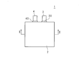
- FIG. 1 is a schematic plan view showing a vanadium solid salt battery 1 according to Embodiment 1 of the present invention.
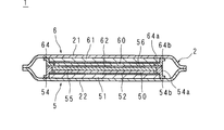
- FIG. 2 is a schematic cross-sectional view taken along the line II-II in FIG. It is typical sectional drawing which shows the vanadium solid salt battery 11 which concerns on Embodiment 2 of this invention.
- It is a graph which shows the relationship between vanadium density
- the vanadium solid salt battery 1 includes an outer bag 2, a positive electrode terminal 3 and a negative electrode terminal 4 protruding from a part of the peripheral edge of the outer bag 2, and an electrode unit 5 constituting a negative electrode. And an electrode unit 6 constituting the positive electrode.
- the positive electrode terminal 3 and the negative electrode terminal 4 protrude from a part of the peripheral edge portion of the outer bag 2 in a state where the base end side is covered with the sealing materials 30 and 40.
- the vanadium solid salt battery 1 alone or a combination of the vanadium solid salt battery 1 and another vanadium solid salt battery may be housed in a case (not shown).
- the electrode unit 5 includes an electrode 50 that is a negative electrode, a conductor 51, a coating film 52, a sealant 54, a water retention film 55, and an ion exchange membrane 56.
- the conductor 51 has a rectangular flat plate shape and is disposed on the upper surface of the lower half 22 in FIG. 2 of the outer bag 2, and the upper surface of the conductor 51 is covered with a coating film 52. Inside the peripheral edge of the upper surface of the coating film 52, a square plate-like electrode 50 having an active material and an electrolytic solution is provided.
- a water retention film 55 having a larger planar area than the electrode 50 is provided on the electrode 50, and an ion exchange membrane 56 having a larger planar area than the water retention film 55 is provided on the water retention film 55.
- the sealant 54 has a frame shape having an edge portion (hereinafter sometimes referred to as a “frame shape”), is bonded to the peripheral edge portion and the half body 22, and the conductor 51 is formed by the half body 22 and the covering portion 52. Seal
- the half 22 is electrolyte impermeable.
- the half 22 is preferably composed of a laminate sheet containing a synthetic resin layer and a metal layer.
- the material for the synthetic resin layer include polypropylene, polyethylene, polyamide such as nylon 6, nylon 66, and the like.
- the thickness of the synthetic resin layer is preferably 5 to 200 ⁇ m. In this case, the battery has good airtightness.
- the material for the metal layer include aluminum, aluminum alloy, copper, copper alloy, iron, stainless steel, titanium, and titanium alloy.
- the thickness of the metal layer is preferably 5 to 100 ⁇ m.
- the thickness of the half body 22 is not particularly limited, but is preferably 15 to 250 ⁇ m. When the thickness is 15 to 250 ⁇ m, the battery has sufficient strength and the battery becomes compact.
- the planar area of the conductor 51 is smaller than the planar area of the half body 22.
- the conductor 51 is preferably made of a metal foil such as copper, aluminum, or nickel.
- the thickness is preferably 5 to 100 ⁇ m. When the thickness is 100 ⁇ m or less, the battery is lightweight and downsized.
- the conductor 51 has a tab (not shown) protruding from a part of the peripheral edge, and the tip of the tab is connected to the negative electrode terminal 4.
- the coating film 52 is formed by coating the upper surface of the conductor 51 with graphite, and has conductivity and electrolyte solution impermeability.
- the thickness of the coating film 52 is preferably 1 to 100 ⁇ m. In this case, the electrical conductivity between the electrode 50 and the conductor 51 is not lowered, and the internal resistance of the battery can be reduced.
- the conductor 51 is not limited to the case where the conductor 51 is covered with the coating film 52 formed by coating with graphite.
- the covering material of the conductor 51 should just be electroconductivity and electrolyte solution non-permeable, and can be covered with an electroconductive film, a sheet-like electroconductive rubber, a graphite sheet, etc.
- the graphite sheet may be arranged on one surface of the conductor 51 through a conductive adhesive sheet.
- the protective layer 52 may not be provided.
- “the conductor 51 (or 61) and the coating film 52 (or 62)” or “the conductor 51 (or 61) alone” means the current collector.
- the electrode 50 is provided inside the peripheral edge of the upper surface of the coating film 52, that is, at a portion other than the peripheral edge of the upper surface of the coating film 52.
- the electrode 50 has vanadium ions whose oxidation number changes between divalent and trivalent or ions containing vanadium whose oxidation number changes between divalent and trivalent due to an oxidation-reduction reaction.
- a precipitate containing a solid compound containing the contained vanadium solid salt as a negative electrode active material is supported.
- the electrode 50 preferably contains vanadium ions whose oxidation number changes between divalent and trivalent by an oxidation-reduction reaction.
- vanadium ions whose oxidation number varies between divalent and trivalent include V 2+ (II) and V 3+ (III).
- vanadium compound that is an active material for the negative electrode include vanadium sulfate (II) (VSO 4 ⁇ nH 2 O) and vanadium sulfate (III) (V 2 (SO 4 ) 3 ⁇ nH 2 O). Mixtures of these can be used.
- n represents 0 or an integer of 1 to 10.
- the coating film 52 is dried by applying or impregnating the coating film 52 with a solution, semi-solid material, or solid material containing a vanadium compound, and drying the coating film 52.
- the semi-solid material include a slurry material obtained by adding an aqueous sulfuric acid solution to a vanadium compound, and a gel material obtained by adding silica or the like to a vanadium compound.
- the electrode 50 is formed by applying a slurry, which is a semi-solid material containing an active material, a binder, and carbon, to the coating film 52 and drying.
- a precipitate containing a solid compound containing an active material by applying or impregnating a solution containing a vanadium compound, a semi-solid product, or a solid product to a carbon material such as carbon felt or drying. May be obtained, and the carbon material may be provided on the coating film 52.
- the electrolyte contained in the electrode 50 is preferably an aqueous sulfuric acid solution.
- the sulfuric acid aqueous solution for example, sulfuric acid having a sulfuric acid concentration of less than 90% by mass can be used.
- the amount of the electrolyte is not excessive or deficient so that the SOC of the battery can be taken from 0 to 100%.
- the amount of the electrolytic solution is, for example, 70 mL of 2M (mol / L) sulfuric acid with respect to 100 g of the vanadium compound.
- the water retention film 55 provided on the electrode 50 is electrolyte permeable.
- the water retaining film 55 is preferably made of a porous material. In this case, water retention is good.
- Specific examples of the water retention film 55 include a porous glass separator, a porous PTFE separator, and carbon paper.
- the thickness of the water retaining film 55 is preferably 50 ⁇ m or more and 135 ⁇ m or less.
- the thickness of the water retention film 55 is not less than 50 ⁇ m and not more than 135 ⁇ m, when the ion exchange membrane 56 is thinned, an increase in resistance due to a decrease in moisture in the ion exchange membrane 56 can be suppressed, and charge / discharge performance is good. .
- the increase in the total thickness of the ion exchange membrane 56 and the water retention membrane 55 can be suppressed, and the vanadium solid salt battery 1 can be made thinner.
- the lower limit of the thickness is more preferably 55 ⁇ m, still more preferably 65 ⁇ m, and particularly preferably 75 ⁇ m.
- the water retaining film 55 is impregnated with water or an aqueous solution.
- the aqueous solution can contain vanadium or sulfur.
- the theoretical capacity of the vanadium solid salt battery 1 can be increased.
- the water retention amount of the water retention film 55 when the size of the water retention film 55 is 27 ⁇ m ⁇ 27 ⁇ m ⁇ 55 ⁇ m, it may be 100 ⁇ l or more.
- the vanadium element concentration in the water retaining film 55 is preferably 5 mol / L or less. In this case, the charge / discharge performance of the vanadium solid salt battery 1 is good.
- the vanadium element concentration in the water retaining film 55 is more preferably 4.8 mol / L or less, and further preferably 4.5 mol / L or less. In this case, the charge / discharge performance of the vanadium solid salt battery 1 is good.
- the sulfur element concentration in the water retaining film 55 is 8 mol / L or less. In this case, the charge / discharge performance of the vanadium solid salt battery 1 is good, and the output capacity and input capacity are good.
- the sulfur element concentration in the water retaining film 55 is more preferably 7.8 mol / L or less, and further preferably 7.5 mol / L or less.
- the sealant 54 has a frame shape as described above, and includes an inner edge portion 54a projecting inwardly at the upper end portion of the rectangular tube-shaped frame body, and an outer edge portion 54b projecting outwardly at the lower end portion of the frame body.
- the sealant 54 is configured such that the outer edge portion 54b is positioned outside the inner edge portion 54a (the outer portion of the electrode 50) in plan view.
- the inner edge 54 a of the sealant 54 is bonded to the peripheral edge of the upper surface of the coating film 52, and the upper part of the inner side surface of the inner edge 54 a is bonded to the side surface of the water retention film 55.
- the outer edge portion 54 b is bonded to the outer surface of the conductor 51 on the surface of the half body 22 on the conductor 51 side.
- the conductor 51 and the coating film 52 are sandwiched between the half body 22 and the sealant 54. That is, the conductor 51 is fixed to the half body 22 in a state where the conductor 51 is sealed by the half body 22, the coating film 52, and the sealant 54.
- the side surface of the conductor 51 may be bonded to the sealant 54, or may not be bonded.
- Examples of the material of the sealant 54 include polypropylene or polyethylene. By using polypropylene or polyethylene, the conductor 51 can be easily sealed by heat welding.
- the ion exchange membrane 56 covers the water retention membrane 55 and is bonded to the upper surface of the inner edge portion 54 a of the sealant 54.
- the ion exchange membrane 56 can pass hydrogen ions (protons) or sulfate ions.
- the vanadium solid salt battery 1 according to the present embodiment has a water retention membrane 55 and can supply moisture to the ion exchange membrane 56. Even if the thickness of the ion exchange membrane 56 is reduced, the ion of the ion exchange membrane 56 is reduced. Since an increase in resistance related to movement can be suppressed, the thickness of the conventional ion exchange membrane is approximately 150 ⁇ m, and can be set to, for example, 10 ⁇ m and 20 ⁇ m.
- the electrode unit 6 has the same configuration as the electrode unit 5, and includes an electrode 60 that is a positive electrode, a conductor 61, a coating film 62, and a sealant 64.
- the conductor 61 has a rectangular flat plate shape and is disposed on the lower surface of the half body 21 of the outer bag 1 in FIG. 2, and the lower surface of the conductor 61 is covered with a coating film 62.
- a square plate electrode 60 having an active material and an electrolytic solution is provided.
- the sealant 64 has a frame shape, and includes an inner edge portion 64a projecting inward at the lower end portion of the rectangular tube-shaped frame body, and an outer edge portion 64b projecting outward at the upper end portion of the frame body.
- the inner edge portion 64 a is bonded to the peripheral edge portion
- the outer edge portion 64 b is bonded to the half body 21, and the sealant 64 seals the conductor 61 with the half body 21 and the covering portion 62.
- the conductor 61 of the electrode unit 6 has a tab (not shown) protruding from a part of the peripheral edge, and the tip of the tab is connected to the positive electrode terminal 3.
- the conductor 61, the coating film 62, and the sealant 64 of the electrode unit 6 are made of the same material as that of the electrode unit 5.
- the electrode 60 has vanadium ions whose oxidation number changes between pentavalent and tetravalent or ions containing vanadium whose oxidation number changes between pentavalent and tetravalent due to an oxidation-reduction reaction.
- a precipitate containing a solid compound containing the contained vanadium solid salt as a positive electrode active material is supported.
- the vanadium ion or the ion containing vanadium contained in the electrode 60 is preferably an ion containing vanadium whose oxidation number changes between pentavalent and tetravalent by an oxidation-reduction reaction.
- the ion containing pentavalent and tetravalent vanadium oxidation number changes between, VO 2+ (IV), VO 2 + (V) are exemplified.
- the vanadium compound supported on the carbon material is vanadium oxide (IV) (VOSO 4 ⁇ nH 2 O), vanadium oxide (V) ((VO 2 ) 2 SO 4 ⁇ nH 2 O). Can be mentioned. Mixtures of these may be used. n represents 0 or an integer of 1 to 5.
- the electrode 60 is formed by applying a slurry, which is a semi-solid material containing a positive electrode active material, a binder, and carbon, to the coating film 62 and drying.
- a slurry which is a semi-solid material containing a positive electrode active material, a binder, and carbon
- a precipitate containing a solid compound containing an active material by applying or impregnating a solution containing a vanadium compound, a semi-solid product, or a solid product to a carbon material such as carbon felt or drying. May be obtained, and the carbon material may be provided on the coating film 62.
- the halves 21 and 22 to which the conductors 61 and 51 are fixed are aligned so that the inside faces each other, and the positive electrode terminal 3 and the negative electrode terminal 4 protrude from a part of the peripheral edge of the halves 21 and 22.
- the outer bag 2 is formed by pressure-contacting and bonding the peripheral edge portion, and the vanadium solid salt battery 1 is obtained.
- the halves 21 and 22 may be integrated from the beginning.
- the charge and discharge of the vanadium solid salt battery using the vanadium solid salt battery 1 is performed using the reactions of the above formulas (1) and (2). At this time, charging / discharging is performed with an external load or a charger via the positive terminal 3 and the negative terminal 4. In the reaction of the formulas (1) and (2), protons move between the electrodes 50 and 60 through the ion exchange membrane 56.
- the vanadium solid salt battery 1 according to the present embodiment configured as described above has the water retention film 55 between the ion exchange membrane 56 and the negative electrode 50, the thickness of the ion exchange membrane 56 is reduced. In this case, the water retention amount of the ion exchange membrane 56 is improved. Therefore, by making the ion exchange membrane 56 thinner, the absolute amount of moisture contained in the ion exchange membrane 56 is reduced, and the ion exchange membrane 56 and the electrode 50 are changed by the change in the ion concentration in the electrode 50 accompanying the charge / discharge reaction during use.
- the vanadium solid salt battery 1 When the osmotic pressure is generated between the two, the moisture in the ion exchange membrane 56 is lost, the permeability of ions containing hydrogen ions is deteriorated, and the resistance value of the ion exchange membrane 56 relating to ion migration is suppressed from increasing. ing. Therefore, the vanadium solid salt battery 1 according to the present embodiment has good charge / discharge performance and a high battery capacity.
- the plane area of the water retention film 55 is equal to or larger than the plane area of the electrode 50, a portion where osmotic pressure is generated between the ion exchange membrane 56 and the electrode 50 when the vanadium solid salt battery 1 is used is covered by the water retention film 55. In other words, it is possible to prevent the moisture in the ion exchange membrane 56 from being lost when the osmotic pressure is generated.
- the planar area of the electrode 50 is larger than the planar area of the water retention film 55, the water content of the water retention film 55 decreases.
- the plane area of the water retention membrane 55 is less than or equal to the plane area of the ion exchange membrane 56, a portion where osmotic pressure is generated between the ion exchange membrane 56 and the electrode 50 when the vanadium solid salt battery 1 is used is formed by the water retention membrane 55.
- the water retention film 55 does not become unnecessarily large, and the planar area of the vanadium solid salt battery 1 is prevented from becoming large.
- the conductor 51 is sealed by the sealant 54, the coating film 52, and the half body 22, and the electrode 50 is surrounded by the water retention film 55, the ion exchange membrane 56, and the sealant 54a. Therefore, the acidic substance related to the electrolytic solution contained in the electrode 50 does not react with the conductor 51, and corrosion of the conductor 51 is prevented.
- the conductor 61 is sealed by the sealant 64, the coating film 62, and the half body 21, and the electrode 60 is surrounded by the ion exchange film 56 and the sealant 64a. The acidic substance related to the liquid does not react with the conductor 61, and corrosion of the conductor 61 is prevented.
- the water retention film 55 is provided so as to contact the negative electrode 50 so as to contact the negative electrode 50.
- the present invention is not limited to this and is provided on the positive electrode 60 side. May be.
- FIG. The vanadium solid salt battery 11 according to Embodiment 2 includes an outer bag 2, a positive terminal and a negative terminal (not shown) protruding from a part of the peripheral edge of the outer bag 2, and two electrode units 7 constituting the negative electrode. And three electrode units 8 constituting the positive electrode and two electrode units 9 constituting the negative electrode.
- An electrode unit 8, an electrode unit 9, an electrode unit 8, an electrode unit 9, an electrode unit 8, and an electrode unit 7 are sequentially stacked on the lower electrode unit 7 in FIG. 3.
- the electrode unit 8 is provided on the inner side of the peripheral portion of the surface of each of the coating films 83, 83, 83 covering the both sides of the rectangular plate-shaped conductor 82, the conductors 82, and the surface of each coating film 83.
- the electrodes 80 and 81, the conductor 82, and the coating film 83 of the electrode unit 8 are made of the same material as the electrode 50, the conductor 51, and the coating film 52 of the electrode unit 5 according to Embodiment 1, It has the same configuration.
- the sealant 84 has a frame shape as described above, and is formed by adhering the upper half 84a and the lower half 84b.
- the half body 84a includes an inner edge portion 84c projecting inward at the upper end portion of the rectangular tube-shaped frame main body, and an outer edge portion 84d projecting outward at the lower end portion of the frame main body.
- the half body 84b includes an inner edge portion 84e projecting inwardly at the lower end portion of the rectangular tube-shaped frame body, and an outer edge portion 84f projecting outward at the upper end portion of the frame body.
- the inner edge portions 84c and 84e of the sealant 84 are bonded to the peripheral edge portions of the surfaces of the coating films 83 and 83, and the outer edge portions 84d and 84f are bonded together.
- the conductor 82 is sealed with coating films 83 and 83 and a sealant 84. Note that the side surface of the conductor 82 may or may not be bonded to the sealant 84.
- Sealant 84 is impermeable to electrolyte solution, and examples of the material include polypropylene or polyethylene. By using polypropylene or polyethylene, the conductor 82 can be easily sealed by heat welding.
- the ion exchange membranes 85 and 86 are such that the electrode unit 7 and the electrode unit 9 have a water retention membrane 75 and water retention membranes 95 and 95, and can supply moisture to the ion exchange membranes 85 and 86. Even if 86 is made thinner, an increase in resistance value related to ion movement can be suppressed, so that the thickness of the ion exchange membranes 85 and 86 can be made thinner, for example, 10 ⁇ m, 20 ⁇ m, and the like.
- the electrode unit 9 includes electrodes 90 and 91, a conductor 92, coating films 93 and 93, a sealant 94, and water retention films 95 and 95.
- the conductor 92 has a rectangular plate shape, and both planes of the conductor 92 are covered with coating films 93 and 93.
- Square plate electrodes 90 and 91 each having an active material and an electrolytic solution are provided inside the peripheral edge portions of the surfaces of the coating films 93 and 93.
- water retention films 95 and 95 having a larger plane area than the electrodes 90 and 91 are provided on the electrodes 90 and 91.
- the water retention membrane 95 in contact with the electrode 90 is in contact with the ion exchange membrane 86 of the electrode unit 8
- the water retention membrane 95 in contact with the electrode 91 is in contact with the ion exchange membrane 85 of the electrode unit 8.
- the sealant 94 includes an upper half 94a and a lower half 94b. Like the sealant 84, the sealant 94 has a frame shape so as to sandwich the coating films 93 and the conductors 92. It is glued to. The upper part of the inner side surface of the inner edge part of the half body 94a of the sealant 94 and the lower part of the inner side surface of the inner edge part of the half body 94b are bonded to the side surfaces of the water retention films 95 and 95.
- the electrodes 90 and 91, the conductor 92, the coating film 93, the sealant 94, and the water retention film 95 of the electrode unit 9 are made of the same material as that of the electrode unit 5 according to the first embodiment.
- the electrode unit 7 has the same configuration as that of the electrode unit 9.
- the electrode unit 7 has a rectangular flat conductor 72, coating films 73 and 73 that cover both surfaces of the conductor 72, and each coating film 73 and conductor 72. And a sealant 74 that is bonded to the peripheral edge of each covering portion 73.
- the sealant 74 includes an upper half 74 a and a lower half 74 b and has the same configuration as the sealant 84.
- the upper electrode unit 7 in FIG. 3 is provided on the inner side of the peripheral portion of the lower surface of the lower coating film 73, and has a square plate electrode 70 having an active material and an electrolytic solution. No electrode is provided on the upper surface of the upper coating film 73. On the lower surface of the electrode 70, a water retention film 75 having a larger planar area than the electrode 70 is provided.
- the upper surface of the half 74 a of the sealant 74 of the upper electrode unit 7 is bonded to the half 21 of the outer bag 2.
- the lower part of the inner side surface of the inner edge of the half body 74 b of the sealant 74 is bonded to the side surface of the water retention film 75.
- the lower electrode unit 7 in FIG. 3 is provided on the inner side of the peripheral edge of the upper surface of the upper coating film 73 and has a square plate-like electrode 71 having an active material and an electrolytic solution. No electrode is provided on the lower surface of the lower coating film 73. On the upper surface of the electrode 71, a water retention film 75 having a larger planar area than the electrode 71 is provided. The lower surface of the half 74 b of the sealant 74 of the lower electrode unit 7 is bonded to the half 22 of the outer bag 2. The upper part of the inner side surface of the inner edge of the half body 74 a of the sealant 74 is bonded to the side surface of the water retention film 75.
- the electrodes 70 and 71, the conductor 72, the coating film 73, the sealant 74, and the water retention film 75 of the electrode unit 7 are made of the same material as the electrode unit 9.
- the conductors 72 and 92 of the electrode units 7 and 9 have tabs (not shown), and the tips of the tabs are connected to the negative terminal in a state where they are overlapped with each other.
- the tips of tabs (not shown) of the conductors 82 of the electrode units 8 are connected to the positive terminal in a state where they are overlapped with each other.
- the halves 21 and 22 to which the conductors 72 and 72 are fixed are aligned so that the inner sides are opposed to each other, and the positive electrode terminal and the negative electrode terminal protrude from a part of the rim part of the halves 21 and 22.
- the outer bag 2 is formed by pressure-contacting and bonding, and the vanadium solid salt battery 11 is obtained.
- the halves 21 and 22 may be integrated from the beginning.
- the reaction of the above formulas (1) and (2) occurs between the electrodes of the vanadium solid salt battery 11.
- Charging / discharging of the vanadium solid salt battery using the vanadium solid salt battery 11 is performed using the reactions of the above-described formulas (1) and (2). At this time, charging / discharging is performed with an external load or a charger via the positive terminal 3 and the negative terminal 4.
- protons move between the electrodes via the ion exchange membranes 85 and 86.
- the electrode units 7 and 7 of the vanadium solid salt battery 11 according to the present embodiment configured as described above have water retention films 75 and 75 that are in contact with the ion exchange membranes 85 and 86 of the electrode units 8 and 8. Since the electrode unit 9 has the water retention membranes 95 and 95 that come into contact with the ion exchange membranes 85 and 86 of the electrode unit 8, when the thickness of the ion exchange membranes 85 and 86 is reduced, water is supplied to the ion exchange membranes 85 and 86. can do.
- the thinning of the ion exchange membranes 85 and 86 reduces the absolute amount of moisture contained in the ion exchange membranes 85 and 86, and the ion exchange is caused by the change in the ion concentration in the corresponding electrode during charge / discharge reaction during use.
- osmotic pressure is generated between the membranes 85 and 86 and the electrodes, moisture in the ion exchange membranes 85 and 86 is lost, and the permeability of ions including hydrogen ions is deteriorated. It is suppressed that the resistance value regarding ion movement increases. Therefore, the vanadium solid salt battery 11 according to the present embodiment has good charge / discharge performance and a high battery capacity.
- the plane area of the water retention membranes 75 and 75 is more than the plane area of the electrodes 70 and 71, osmotic pressure is generated between the ion exchange membranes 86 and 85 and the electrodes 70 and 71 when the vanadium solid salt battery 11 is used.
- the portion to be covered can be covered with the water retention membranes 75, 75, and the water content of the ion exchange membranes 86, 85 is prevented from being reduced by the osmotic pressure.
- the plane area of the water retention membranes 75 and 75 is less than or equal to the plane area of the ion exchange membranes 86 and 85, an osmotic pressure is generated between the ion exchange membranes 86 and 85 and the electrodes 70 and 71 when the vanadium solid salt battery 11 is used.
- the generated portion can be covered with the water retaining films 75 and 75, and the water retaining film 75 does not become unnecessarily large.
- the planar area of the water retention membranes 95 and 95 is equal to or larger than the planar area of the electrodes 90 and 91, a portion where osmotic pressure is generated between the ion exchange membranes 86 and 85 and the electrodes 90 and 91 when the vanadium solid salt battery 11 is used. Can be covered by the water retention membranes 95, 95, and the water content of the ion exchange membranes 86, 85 is prevented from being reduced by the osmotic pressure.
- the plane area of the water retention membranes 95 and 95 is equal to or less than the plane area of the ion exchange membranes 86 and 85, an osmotic pressure is generated between the ion exchange membranes 86 and 85 and the electrodes 90 and 91 when the vanadium solid salt battery 11 is used.
- the generated portion can be covered by the water retention films 95 and 95, and the water retention films 95 and 95 are not unnecessarily large. As described above, the planar area of the vanadium solid salt battery 11 is prevented from increasing.
- the conductor 72 of the electrode unit 7 is sealed with the sealant 74, the coating films 73 and 73, and the half body 21 (or 22), and the electrode 70 (or 71) is the water retention film.
- the ion exchange membrane 86 (or 85) and the sealant 74 the acidic substance related to the electrolyte contained in the electrode 70 (or 71) does not react with the conductor 72, and the conductor 72 corrosion is prevented.
- the conductor 92 of the electrode unit 9 is sealed with the sealant 94 and the covering films 93 and 93, and the electrode 90 (or 91) is connected with the water retention film 95 and the ion exchange membrane 86 (or 85) and the sealant 94. Therefore, the acidic substance related to the electrolyte contained in the electrode 90 (or 91) does not react with the conductor 92, and corrosion of the conductor 92 is prevented.
- the conductor 82 of the electrode unit 8 is sealed by the sealant 84 and the coating films 83 and 83, and the electrode 80 (or 81) is surrounded by the ion exchange membrane 85 (or 86) and the sealant 84. Therefore, the acidic substance related to the electrolyte contained in the electrode 80 (or 81) does not react with the conductor 82, and corrosion of the conductor 82 is prevented.
- the polarities of the electrodes 70 and 71 of the electrode unit 7, the electrodes 80 and 81 of the electrode unit 8, and the electrodes 90 and 91 of the electrode unit 9 are not limited to the above case.
- the polarities of the electrodes of the electrode units 7, 8, 9 may be considered so that the polarities of the electrodes facing each other across the ion exchange membranes 85, 86 of the electrode unit 8 are different.
- the battery capacity is improved and the battery design Diversification can be achieved.
- the present invention is not limited to this and may be provided on the positive electrode side.
- Vanadium Element Concentration in Water Retention Film and Battery Performance For each of the vanadium solid salt batteries 1 of Examples 1 to 5 having the configuration of the first embodiment, the element concentration (mol / L) shown in Table 1 below is added to each water retention film 55. ) was evaluated when the battery was impregnated with a water retention film impregnating solution containing vanadium (V) and sulfur (S) during assembly. A porous glass “TGP-015A” manufactured by Nippon Sheet Glass Co., Ltd. was used as the water retention membrane 55, and an anion exchange membrane manufactured by Fumatech was used as the ion exchange membrane 56. The thickness of the water retention membrane 55 and the ion exchange membrane 56 is 82 ⁇ m and 10 ⁇ m, respectively.
- V [mol / L] (same as V concentration [mol / L] in FIG. 4) and “S [mol / L]” in “Concentration of solution in water retention membrane during operation” in Table 1 are ICP -Concentrations of vanadium and sulfur elements measured using MS [Inductively Coupled Plasma Mass Spectrometer]. "50 mA / cm 2 at the output capacity" of FIG.
- the “input capacity at cm 2 ” is a discharge capacity when a current value of 50 mA per 1 cm 2 of electrode is inputted and then discharged at a current value of 1.5 mA per 1 cm 2 of electrode.
- “Rated capacity” was charged at a current value of the electrode 1 cm 2 per 1.5 mA, a discharge capacity when the output current value of the electrode 1 cm 2 per 1.5 mA.
- FIG. 4 shows that when the vanadium concentration of the water retention film 55 is 5 mol / L or less, both the input capacity and the output capacity at 50 mA / cm @ 2 are good.
- the vanadium concentration of the water retaining film 55 is more preferably 4.8 mol / L or less, and further preferably 4.5 mol / L or less.
- FIG. 5 shows that when the sulfur concentration is 8 mol / L or less, both the input capacity and output capacity at 50 mA / cm 2 are good.
- the sulfur concentration is more preferably 7.8 mol / L or less, and further preferably 7.5 mol / L or less.
- “Discharge capacity at 50 mA / cm 2 ” refers to the voltage of the battery when the current is discharged at a current density of 50 mA / cm 2 per electrode area from the state where the open circuit voltage (OCV) is 1.45 V. 1. Current capacity when discharge is achieved until 20V is reached.
- the thickness of the water-holding film 55 is 50 ⁇ m or more 135 ⁇ m or less, it is found that good both 50 mA / cm 2 at the discharge capacity and 50 mA / cm 2 at charge capacity.
- the lower limit of the thickness is more preferably 55 ⁇ m, still more preferably 65 ⁇ m, and particularly preferably 75 ⁇ m.
- the vanadium solid salt battery according to the present invention is a positive electrode including a current collector and a positive electrode including a positive electrode active material, and the positive electrode active material is oxidized between pentavalent and tetravalent by an oxidation-reduction reaction.
- a positive electrode containing a positive electrode, a current collector, and a negative electrode active material the vanadium ion containing a vanadium ion containing a vanadium ion containing a vanadium ion, or an ion containing vanadium whose oxidation number changes between pentavalent and tetravalent
- the negative electrode active material contains vanadium ions whose oxidation number changes between divalent and trivalent or vanadium whose oxidation number changes between divalent and trivalent by an oxidation-reduction reaction.
- the vanadium solid salt battery of the present invention since the water retention membrane is provided between the ion exchange membrane and the positive electrode or the negative electrode, when water is supplied to the ion exchange membrane and the thickness of the ion exchange membrane is reduced, the ions of the ion exchange membrane An increase in the resistance value related to movement is suppressed. Therefore, the vanadium solid salt battery of the present invention has good charge / discharge performance and high battery capacity (output capacity and input capacity).
- the vanadium solid salt battery according to the present invention is characterized in that, in the above-described invention, the planar area of the water retention film is equal to or greater than the planar area of the positive electrode or the negative electrode provided with the water retention film.
- the portion where osmotic pressure is generated between the ion exchange membrane and the electrode when the battery is used can be covered by the water retention membrane, and moisture in the ion exchange membrane may be lost when the osmotic pressure is generated. It is suppressed.
- the planar area of the electrode is larger than the planar area of the water retention film, the water content of the water retention film decreases.
- the vanadium solid salt battery according to the present invention is characterized in that, in any one of the above-described inventions, a planar area of the water retention membrane is equal to or less than a planar area of the ion exchange membrane.
- the planar area of the electrode is smaller than the planar area of the ion exchange membrane, and it is only necessary to cover the portion where osmotic pressure is generated between the ion exchange membrane and the electrode when the battery is used. Is less than or equal to the planar area of the ion exchange membrane. As a result, the water retention film is not unnecessarily increased, and the planar area of the battery is prevented from increasing.
- the vanadium solid salt battery according to the present invention is characterized in that, in any of the above-mentioned inventions, the water retention film is made of a porous material.
- the water retention of the water retention film is good.
- the vanadium solid salt battery according to the present invention is characterized in that, in any one of the above-described inventions, the thickness of the water retention film is 50 ⁇ m or more and 135 ⁇ m or less.
- the present invention it is possible to improve the charge / discharge performance of the vanadium solid salt battery by suppressing an increase in the resistance value due to the thinning of the ion exchange membrane, and to increase the total thickness of the ion exchange membrane and the water retention membrane. It is possible to reduce the overall thickness of the battery.
- the vanadium solid salt battery according to the present invention is characterized in that, in any of the above-described inventions, the vanadium element concentration in the water retaining film is 5 mol / L or less, and the sulfur element concentration is 8 mol / L or less. To do.
- the vanadium solid salt battery has good charge / discharge performance.
- Electrode unit 50 60, 70, 71, 80, 81, 90, 91 Electrode 51, 61, 72, 82 , 92 Conductor 52, 62, 73, 83, 93 Coating membrane 54, 64, 74, 84, 94 Sealant 55, 75, 95 Water retention membrane 56, 85, 86 Ion exchange membrane
Landscapes
- Engineering & Computer Science (AREA)
- Manufacturing & Machinery (AREA)
- Chemical & Material Sciences (AREA)
- Chemical Kinetics & Catalysis (AREA)
- Electrochemistry (AREA)
- General Chemical & Material Sciences (AREA)
- Secondary Cells (AREA)
- Battery Electrode And Active Subsutance (AREA)
- Cell Separators (AREA)
- Fuel Cell (AREA)
Abstract
イオン交換膜を薄型化した場合に、イオン交換膜のイオン移動に関する抵抗値が増加することがなく、良好な充放電性能を有するバナジウム固体塩電池を提供する。 バナジウム固体塩電池1は、バナジウムイオン、又はバナジウムを含むイオンを含有する活物質を含む電極50を、被覆膜52を介し導電体51に設けてなり、負極を構成する電極ユニット5と、バナジウムイオン、又はバナジウムを含むイオンを含有する活物質を含む電極60を、被覆膜62を介し導電体61に設けてなり、正極を構成する電極ユニット6とを備える。電極ユニット5の電極50の表面には保水膜55が設けられ、保水膜55の表面にはイオン交換膜56が設けられており、イオン交換膜56を挟んで、電極50と電極60とが対向する。
Description
本発明は、活物質として、バナジウムイオン又はバナジウムを含むイオンを含有し、活物質による酸化還元反応を利用して充放電を行うバナジウム固体塩電池に関する。
電池は、デジタル家電製品、電気自動車、ハイブリッド自動車及び太陽光発電設備等に広く用いられている。この電池として、リチウムイオン二次電池、バナジウム固体塩電池(特許文献1)等が挙げられる。バナジウム固体塩電池は、活物質による酸化還元反応を利用して充放電を行う。活物質としては、バナジウムイオン又はバナジウムを含むイオンが用いられる。
バナジウム固体塩電池は、活物質及び酸性の電解液を有する電極と、電極に対向する銅等の導電体とを備える電極ユニットを、極性が異なる電極がイオン交換膜を介して対向する状態で複数並設し、外装袋に収容することにより構成される。このバナジウム固体塩電池は、さらに、ケースに収容されることもある。
このタイプのバナジウム固体塩電池においては、エネルギー密度向上の観点から、複数の電極ユニットを外装袋に収容するため、外装袋内の電池の構成部材の薄型化が求められている。特に、従来の前記イオン交換膜の厚みは例えば150μmと厚く、イオン交換膜のさらなる薄型化が望まれている。
しかし、イオン交換膜を薄型化した場合、イオン交換膜に含まれる水分の絶対量が減少する。そのため、使用時に充放電反応に伴う電極中のイオン濃度の変化によりイオン交換膜と電極との間で浸透圧が発生する際にイオン交換膜中の水分が失われ、水素イオンを含むイオンの透過性が悪化し、イオン交換膜のイオン移動に関する抵抗値が増加する虞があった。抵抗値が増加した場合、バナジウム固体塩電池の充放電性能が低下する。
しかし、イオン交換膜を薄型化した場合、イオン交換膜に含まれる水分の絶対量が減少する。そのため、使用時に充放電反応に伴う電極中のイオン濃度の変化によりイオン交換膜と電極との間で浸透圧が発生する際にイオン交換膜中の水分が失われ、水素イオンを含むイオンの透過性が悪化し、イオン交換膜のイオン移動に関する抵抗値が増加する虞があった。抵抗値が増加した場合、バナジウム固体塩電池の充放電性能が低下する。
本発明は、斯かる事情に鑑みてなされたものであり、イオン交換膜を薄型化した場合に、イオン交換膜のイオン移動に関する抵抗値が増加することがなく、良好な充放電性能を有するバナジウム固体塩電池を提供することを目的とする。
本発明に係るバナジウム固体塩電池は、集電体と、正極活物質を含む正極電極とを含む正極であり、前記正極活物質が、酸化還元反応によって、5価及び4価の間で酸化数が変化するバナジウムイオン、又は5価及び4価の間で酸化数が変化するバナジウムを含むイオンを含有するバナジウム固体塩を含む、前記正極と、集電体と、負極活物質を含む負電電極とを含む負極であり、前記負極活物質が、酸化還元反応によって、2価及び3価の間で酸化数が変化するバナジウムイオン、又は2価及び3価の間で酸化数が変化するバナジウムを含むイオンを含有するバナジウム固体塩を含む、前記負極と、水素イオンを通過させ、前記正極電極と前記負極電極との間に設けられたイオン交換膜と、前記イオン交換膜と、前記正極電極又は前記負極電極との間に設けられた保水膜とを備えることを特徴とする。
本発明によれば、イオン交換膜と、正極電極又は負極電極との間に保水膜を有するので、イオン交換膜に水分が供給され、イオン交換膜の厚みを薄くした場合に、イオン交換膜のイオン移動に関する抵抗値が増加することが抑制される。
従って、本発明のバナジウム固体塩電池は良好な充放電性能を有し、高い電池容量を有する。
従って、本発明のバナジウム固体塩電池は良好な充放電性能を有し、高い電池容量を有する。
以下、本発明をその実施の形態を示す図面に基づいて詳述する。
実施の形態1.
図1及び図2に示すように、バナジウム固体塩電池1は、外装袋2と、外装袋2の周縁部の一部から突出した正極端子3及び負極端子4と、負極を構成する電極ユニット5と、正極を構成する電極ユニット6とを備える。正極端子3,負極端子4は、基端部側がシール材30,40に覆われた状態で、外装袋2の周縁部の一部から突出している。このバナジウム固体塩電池1単体、又は該バナジウム固体塩電池1と他のバナジウム固体塩電池とを組み合わせてケース(不図示)に収容してもよい。
実施の形態1.
図1及び図2に示すように、バナジウム固体塩電池1は、外装袋2と、外装袋2の周縁部の一部から突出した正極端子3及び負極端子4と、負極を構成する電極ユニット5と、正極を構成する電極ユニット6とを備える。正極端子3,負極端子4は、基端部側がシール材30,40に覆われた状態で、外装袋2の周縁部の一部から突出している。このバナジウム固体塩電池1単体、又は該バナジウム固体塩電池1と他のバナジウム固体塩電池とを組み合わせてケース(不図示)に収容してもよい。
電極ユニット5は、負極電極である電極50、導電体51、被覆膜52、シーラント54、保水膜55、及びイオン交換膜56を備える。
導電体51は角型平板状をなし、前記外装袋2の、図2における下側の半体22の上面に配されており、導電体51の上面は被覆膜52により覆われている。被覆膜52の上面の周縁部の内側には、活物質及び電解液を有する角型平板状の電極50が設けられている。電極50上には、電極50より平面面積が大きい保水膜55が設けられており、保水膜55上には、保水膜55より平面面積が大きいイオン交換膜56が設けられている。シーラント54は縁部を有する枠状(以下、「額縁状」と称する場合もある。)をなし、前記周縁部及び半体22に接着され、半体22及び被覆部52とにより導電体51を封止する。
導電体51は角型平板状をなし、前記外装袋2の、図2における下側の半体22の上面に配されており、導電体51の上面は被覆膜52により覆われている。被覆膜52の上面の周縁部の内側には、活物質及び電解液を有する角型平板状の電極50が設けられている。電極50上には、電極50より平面面積が大きい保水膜55が設けられており、保水膜55上には、保水膜55より平面面積が大きいイオン交換膜56が設けられている。シーラント54は縁部を有する枠状(以下、「額縁状」と称する場合もある。)をなし、前記周縁部及び半体22に接着され、半体22及び被覆部52とにより導電体51を封止する。
以下、電極ユニット5の各部、及び外装袋2の半体22について詳述する。
半体22は電解液非透過性である。半体22は、合成樹脂層及び金属層を含有するラミネートシートからなるのが好ましい。
合成樹脂層の材料としては、ポリプロピレン、ポリエチレン、ナイロン6,ナイロン66等のポリアミド等が挙げられる。合成樹脂層の厚みは、5~200μmであるのが好ましい。この場合、電池は、良好な気密性を有する。
金属層の材料としては、アルミニウム、アルミニウム合金、銅、銅合金、鉄、ステンレス、チタン、チタン合金等が挙げられる。金属層の厚みは、5~100μmであるのが好ましい。この場合、金属層にピンホール等を発生させることなく、良好な遮水性を保持することができる。
半体22の厚みは特に限定されないが、15~250μmであるのが好ましい。厚みが15~250μmである場合、十分な強度を有するとともに、電池がコンパクトになる。
半体22は電解液非透過性である。半体22は、合成樹脂層及び金属層を含有するラミネートシートからなるのが好ましい。
合成樹脂層の材料としては、ポリプロピレン、ポリエチレン、ナイロン6,ナイロン66等のポリアミド等が挙げられる。合成樹脂層の厚みは、5~200μmであるのが好ましい。この場合、電池は、良好な気密性を有する。
金属層の材料としては、アルミニウム、アルミニウム合金、銅、銅合金、鉄、ステンレス、チタン、チタン合金等が挙げられる。金属層の厚みは、5~100μmであるのが好ましい。この場合、金属層にピンホール等を発生させることなく、良好な遮水性を保持することができる。
半体22の厚みは特に限定されないが、15~250μmであるのが好ましい。厚みが15~250μmである場合、十分な強度を有するとともに、電池がコンパクトになる。
導電体51の平面面積は半体22の平面面積より小さい。
導電体51は、銅、アルミニウム、ニッケル等の金属箔からなるのが好ましい。厚みは、5~100μmであるのが好ましい。厚みが100μm以下である場合、電池は、軽量かつ小型化される。
導電体51は、周縁部の一部から突出したタブ(不図示)を有し、タブの先端部は負極端子4に接続されている。
導電体51は、銅、アルミニウム、ニッケル等の金属箔からなるのが好ましい。厚みは、5~100μmであるのが好ましい。厚みが100μm以下である場合、電池は、軽量かつ小型化される。
導電体51は、周縁部の一部から突出したタブ(不図示)を有し、タブの先端部は負極端子4に接続されている。
被覆膜52は、導電体51の上面に黒鉛でコーティングすることにより形成されており、導電性かつ電解液非透過性を有する。
被覆膜52の厚みは1~100μmであるのが好ましい。この場合、電極50と導電体51との電気伝導性が低下することがなく、電池の内部抵抗を小さくすることができる。
なお、導電体51は黒鉛でコーティングしてなる被覆膜52で覆う場合に限定されるものではない。導電体51の被覆材が導電性かつ電解液非透過性であればよく、導電性フィルム、シート状の導電性ゴム、グラファイトシート等で覆うことができる。例えば導電性の接着シートを介して、グラファイトシートを導電体51の一面に配する構成としてもよい。また、電解液が酸性又はアルカリ性ではなく、導電体51が腐食等される虞がない場合は、保護層52を備えていなくてもよい。
本実施の形態において、「導電体51(又は61)及び被覆膜52(又は62)」、又は「導電体51(又は61)単体」が集電体を意味する。
被覆膜52の厚みは1~100μmであるのが好ましい。この場合、電極50と導電体51との電気伝導性が低下することがなく、電池の内部抵抗を小さくすることができる。
なお、導電体51は黒鉛でコーティングしてなる被覆膜52で覆う場合に限定されるものではない。導電体51の被覆材が導電性かつ電解液非透過性であればよく、導電性フィルム、シート状の導電性ゴム、グラファイトシート等で覆うことができる。例えば導電性の接着シートを介して、グラファイトシートを導電体51の一面に配する構成としてもよい。また、電解液が酸性又はアルカリ性ではなく、導電体51が腐食等される虞がない場合は、保護層52を備えていなくてもよい。
本実施の形態において、「導電体51(又は61)及び被覆膜52(又は62)」、又は「導電体51(又は61)単体」が集電体を意味する。
電極50は、上述したように被覆膜52の上面の周縁部の内側に、即ち被覆膜52の上面の周縁部以外の部分に設けられている。
電極50は、被覆膜52に、酸化還元反応によって、2価及び3価の間で酸化数が変化するバナジウムイオン、又は2価及び3価の間で酸化数が変化するバナジウムを含むイオンを含有するバナジウム固体塩を負極活物質として含有する固体状の化合物を含む析出物を担持させてなる。
電極50は、被覆膜52に、酸化還元反応によって、2価及び3価の間で酸化数が変化するバナジウムイオン、又は2価及び3価の間で酸化数が変化するバナジウムを含むイオンを含有するバナジウム固体塩を負極活物質として含有する固体状の化合物を含む析出物を担持させてなる。
電極50は、酸化還元反応によって、2価及び3価の間で酸化数が変化するバナジウムイオンを含むことが好ましい。2価及び3価の間で酸化数が変化するバナジウムイオンとしては、V2+(II)、V3+(III )が例示される。
負極用の活物質であるバナジウム化合物としては、硫酸バナジウム(II)(VSO4 ・nH2 O)、硫酸バナジウム(III )(V2 (SO4 )3 ・nH2 O)が挙げられる。これらの混合物が用いられ得る。nは、0又は1~10の整数を示す。
負極用の活物質であるバナジウム化合物としては、硫酸バナジウム(II)(VSO4 ・nH2 O)、硫酸バナジウム(III )(V2 (SO4 )3 ・nH2 O)が挙げられる。これらの混合物が用いられ得る。nは、0又は1~10の整数を示す。
バナジウム化合物を含む溶液、半固体状物、又は固体状物を、被覆膜52に塗布又は含侵させた後、乾燥させることで、被覆膜52に析出物が担持される。半固体状物としては、バナジウム化合物に硫酸水溶液を加えたスラリー状物や、バナジウム化合物にシリカ等を加えたゲル状物等が挙げられる。具体的には活物質、バインダー、及び炭素を含む半固体状物であるスラリーを、被覆膜52に塗布、乾燥して、電極50を形成する例が挙げられる。
なお、炭素フェルト等の炭素材に、バナジウム化合物を含む溶液、半固体状物、又は固体状物を塗布又は含侵させ、乾燥させることにより、活物質を含有する固体状の化合物を含む析出物を担持させた炭素材を得、該炭素材を被覆膜52上に設けることにしてもよい。
なお、炭素フェルト等の炭素材に、バナジウム化合物を含む溶液、半固体状物、又は固体状物を塗布又は含侵させ、乾燥させることにより、活物質を含有する固体状の化合物を含む析出物を担持させた炭素材を得、該炭素材を被覆膜52上に設けることにしてもよい。
電極50に含まれる電解液は、硫酸水溶液であるのが好ましい。硫酸水溶液として、例えば硫酸の濃度が90質量%未満の硫酸を用いることができる。電解液は、電池のSOCを0~100%まで取り得るのに過不足のない量である。電解液の量は、例えばバナジウム化合物100gに対して、2M(mol /L)の硫酸70mLである。
電極50上に設けられる保水膜55は電解液透過性である。保水膜55は多孔質材料からなるのが好ましい。この場合、保水性が良好である。
保水膜55として、具体的には、多孔質ガラスセパレータ、多孔質PTFEセパレータ、及びカーボンペーパー等が挙げられる。
保水膜55として、具体的には、多孔質ガラスセパレータ、多孔質PTFEセパレータ、及びカーボンペーパー等が挙げられる。
保水膜55の厚みは50μm以上135μm以下であることが好ましい。保水膜55の厚みが50μm以上135μm以下である場合、イオン交換膜56を薄型化したときに、イオン交換膜56の水分低下に伴う抵抗増加を抑制することができ、充放電性能が良好である。そして、イオン交換膜56と保水膜55との合計厚みの増加を抑制して、バナジウム固体塩電池1の薄型化を図ることができる。厚みの下限は、より好ましくは55μm、さらに好ましくは65μm、特に好ましくは75μmである。
保水膜55には水、又は水溶液を含浸させる。水溶液にはバナジウム、又は硫黄を含むことができる。特にバナジウムを含む水溶液を含浸させる場合、バナジウム固体塩電池1の理論的な容量を増加させることができる。
保水膜55の保水量の一例として、保水膜55の大きさが27μm×27μm×55μmであるときに、100μl以上である場合が挙げられる。
保水膜55の保水量の一例として、保水膜55の大きさが27μm×27μm×55μmであるときに、100μl以上である場合が挙げられる。
保水膜55中のバナジウム元素濃度は5mol /L以下であることが好ましい。この場合、バナジウム固体塩電池1の充放電性能が良好である。保水膜55中のバナジウム元素濃度は4.8mol /L以下であることがより好ましく、4.5mol /L以下であることがさらに好ましい。この場合、バナジウム固体塩電池1の充放電性能が良好である。
保水膜55中の硫黄元素濃度は8mol /L以下であることが好ましい。この場合、バナジウム固体塩電池1の充放電性能が良好であり、出力容量及び入力容量が良好である。保水膜55中の硫黄元素濃度は7.8mol /L以下であることがより好ましく、7.5mol /L以下であることがさらに好ましい。
シーラント54は上述したように額縁状をなし、角筒状の枠本体の上端部に、内側に張り出した内側縁部54aを備え、枠本体の下端部に、外側に張り出した外側縁部54bを備える。即ち、シーラント54は平面視で、内側縁部54a(電極50の外側部分)の外側に、外側縁部54bが位置するように構成されている。
シーラント54の内側縁部54aは被覆膜52の上面の周縁部に接着されており、内側縁部54aの内側面の上部は、保水膜55の側面に接着されている。
外側縁部54bは半体22の導電体51側の面の、導電体51の外側に接着されている。これにより、導電体51及び被覆膜52は、半体22とシーラント54とに挟着されている。即ち、半体22、被覆膜52、及びシーラント54により、導電体51は封止された状態で、導電体51は半体22に固定されている。なお、導電体51の側面はシーラント54に接着されていてもよく、接着されていなくてもよい。
外側縁部54bは半体22の導電体51側の面の、導電体51の外側に接着されている。これにより、導電体51及び被覆膜52は、半体22とシーラント54とに挟着されている。即ち、半体22、被覆膜52、及びシーラント54により、導電体51は封止された状態で、導電体51は半体22に固定されている。なお、導電体51の側面はシーラント54に接着されていてもよく、接着されていなくてもよい。
シーラント54の材料としては、例えばポリプロピレン又はポリエチレン等が挙げられる。ポロプロピレン又はポリエチレン等を用いることにより、熱溶着で容易に導電体51を封止することが可能となる。
イオン交換膜56は保水膜55を覆い、シーラント54の内側縁部54aの上面に接着されている。
イオン交換膜56は水素イオン(プロトン)又は硫酸イオンを通過させることができる。
本実施の形態に係るバナジウム固体塩電池1は保水膜55を有し、イオン交換膜56に水分を供給することができ、イオン交換膜56の厚みを薄くしても、イオン交換膜56のイオン移動に関する抵抗の増加を抑制することができるので、従来のイオン交換膜の厚みは略150μmであったところ、例えば10μm、20μmにすることができる。
イオン交換膜56は水素イオン(プロトン)又は硫酸イオンを通過させることができる。
本実施の形態に係るバナジウム固体塩電池1は保水膜55を有し、イオン交換膜56に水分を供給することができ、イオン交換膜56の厚みを薄くしても、イオン交換膜56のイオン移動に関する抵抗の増加を抑制することができるので、従来のイオン交換膜の厚みは略150μmであったところ、例えば10μm、20μmにすることができる。
電極ユニット6は電極ユニット5と同様の構成を有し、正極電極である電極60、導電体61、被覆膜62、及びシーラント64を備える。導電体61は角型平板状をなし、外装袋1の半体21の図2における下面に配されており、導電体61の下面は被覆膜62により覆われている。被覆膜62の下面の周縁部の内側には、活物質及び電解液を有する角型平板状の電極60が設けられている。シーラント64は額縁状をなし、角筒状の枠本体の下端部に、内側に張り出した内側縁部64aを備え、枠本体の上端部に、外側に張り出した外側縁部64bを備える。内側縁部64aは前記周縁部に接着され、外側縁部64bは半体21に接着され、シーラント64は半体21及び被覆部62とにより導電体61を封止する。
電極ユニット6の導電体61は、周縁部の一部から突出したタブ(不図示)を有し、タブの先端部は正極端子3に接続されている。
電極ユニット6の導電体61、被覆膜62、及びシーラント64は電極ユニット5と同様の材料を用いてなる。
電極ユニット6の導電体61は、周縁部の一部から突出したタブ(不図示)を有し、タブの先端部は正極端子3に接続されている。
電極ユニット6の導電体61、被覆膜62、及びシーラント64は電極ユニット5と同様の材料を用いてなる。
電極60は、被覆膜62に、酸化還元反応によって、5価及び4価の間で酸化数が変化するバナジウムイオン、又は5価及び4価の間で酸化数が変化するバナジウムを含むイオンを含有するバナジウム固体塩を正極活物質として含有する固体状の化合物を含む析出物を担持させてなる。
電極60に含まれるバナジウムイオン又はバナジウムを含むイオンとしては、酸化還元反応によって、5価及び4価の間で酸化数が変化するバナジウムを含むイオンであるのが好ましい。5価及び4価の間で酸化数が変化するバナジウムを含むイオンとしては、VO2+(IV)、VO2 +(V )が例示される。
電極60に含まれるバナジウムイオン又はバナジウムを含むイオンとしては、酸化還元反応によって、5価及び4価の間で酸化数が変化するバナジウムを含むイオンであるのが好ましい。5価及び4価の間で酸化数が変化するバナジウムを含むイオンとしては、VO2+(IV)、VO2 +(V )が例示される。
正極用の活物質として、炭素材に担持させるバナジウム化合物は、酸化硫酸バナジウム(IV)(VOSO4 ・nH2 O)、酸化硫酸バナジウム(V)((VO2 )2 SO4 ・nH2 O)を挙げることができる。これらの混合物を用いてもよい。nは、0又は1~5の整数を示す。
具体的には正極活物質、バインダー、及び炭素を含む半固体状物であるスラリーを、被覆膜62に塗布、乾燥して、電極60を形成する例が挙げられる。
なお、炭素フェルト等の炭素材に、バナジウム化合物を含む溶液、半固体状物、又は固体状物を塗布又は含侵させ、乾燥させることにより、活物質を含有する固体状の化合物を含む析出物を担持させた炭素材を得、該炭素材を被覆膜62上に設けることにしてもよい。
なお、炭素フェルト等の炭素材に、バナジウム化合物を含む溶液、半固体状物、又は固体状物を塗布又は含侵させ、乾燥させることにより、活物質を含有する固体状の化合物を含む析出物を担持させた炭素材を得、該炭素材を被覆膜62上に設けることにしてもよい。
以上のように導電体61,51が固定された半体21,22を内側が対向するように合わせ、半体21,22の周縁部の一部から正極端子3及び負極端子4が突出する状態で、周縁部を圧接し、接着することにより外装袋2が形成され、バナジウム固体塩電池1が得られる。なお、半体21,22は最初から一体化されていてもよい。
以上のように構成されたバナジウム固体塩電池1の電極ユニット5の電極50と電極ユニット6の電極60との間において、下記式(1)及び(2)の反応が生じる。
正極:VOX2 ・nH2 O(s)⇔VO2 X・(n-1)H2 O(s)+HX+H+ +e- (1)
負極:VX3 ・nH2 O(s)+H++e- ⇔VX2 ・nH2 O(s)+HX (2)
式中、Xは1価の陰イオンを表す。Xがm価の陰イオンである場合、結合係数(1/m)が考慮される。nは種々の値をとり得る。
正極:VOX2 ・nH2 O(s)⇔VO2 X・(n-1)H2 O(s)+HX+H+ +e- (1)
負極:VX3 ・nH2 O(s)+H++e- ⇔VX2 ・nH2 O(s)+HX (2)
式中、Xは1価の陰イオンを表す。Xがm価の陰イオンである場合、結合係数(1/m)が考慮される。nは種々の値をとり得る。
前記式(1)及び(2)の反応を利用してバナジウム固体塩電池1を用いたバナジウム固体塩電池の充放電が行われる。このとき、正極端子3,負極端子4を介して、外部の負荷又は充電器等との間で充放電が行われる。式(1)及び(2)の反応においてイオン交換膜56を介して、電極50,60間でプロトンが移動する。
以上のように構成された本実施の形態に係るバナジウム固体塩電池1は、イオン交換膜56と、負極の電極50との間に保水膜55を有するので、イオン交換膜56の厚みを薄くした場合に、イオン交換膜56の保水量が向上する。従って、イオン交換膜56の薄型化により、イオン交換膜56に含まれる水分の絶対量が減少し、使用時に充放電反応に伴う電極50中のイオン濃度の変化によりイオン交換膜56と電極50との間で浸透圧が発生する際にイオン交換膜56中の水分が失われ、水素イオンを含むイオンの透過性が悪化し、イオン交換膜56のイオン移動に関する抵抗値が増加することが抑制されている。
よって、本実施の形態に係るバナジウム固体塩電池1は良好な充放電性能を有し、高い電池容量を有する。
よって、本実施の形態に係るバナジウム固体塩電池1は良好な充放電性能を有し、高い電池容量を有する。
そして、保水膜55の平面面積が電極50の平面面積以上であるので、バナジウム固体塩電池1の使用時にイオン交換膜56と電極50との間で浸透圧が発生する部分を保水膜55によりカバーすることができ、即ち、浸透圧の発生時にイオン交換膜56中の水分が失われることが防止される。電極50の平面面積の方が保水膜55の平面面積より大きい場合、保水膜55の水分量が減少する。
保水膜55の平面面積は、イオン交換膜56の平面面積以下であるので、バナジウム固体塩電池1の使用時にイオン交換膜56と電極50との間で浸透圧が発生する部分を保水膜55によりカバーすることができるとともに、保水膜55が不要に大きくならず、バナジウム固体塩電池1の平面面積が大きくなることが防止されている。
そして、本実施の形態においては、導電体51は、シーラント54、被覆膜52、及び半体22により封止され、電極50は保水膜55及びイオン交換膜56と、シーラント54aとにより包囲されているので、電極50に含まれる電解液に係る酸性物質が導電体51と反応することがなく、導電体51の腐食が防止されている。同様に、導電体61は、シーラント64、被覆膜62、及び半体21により封止され、電極60はイオン交換膜56と、シーラント64aとにより包囲されているので、電極60に含まれる電解液に係る酸性物質が導電体61と反応することがなく、導電体61の腐食が防止されている。
なお、本実施の形態においては、保水膜55を負極の電極50に当接するように設けた場合につき説明しているが、これに限定されるものではなく、正極の電極60側に設けることにしてもよい。
実施の形態2.
実施の形態2に係るバナジウム固体塩電池11は、外装袋2と、外装袋2の周縁部の一部から突出した正極端子及び負極端子(不図示)と、負極を構成する2つの電極ユニット7と、正極を構成する3つの電極ユニット8と、負極を構成する2つの電極ユニット9とを備える。図3の下側の電極ユニット7に、電極ユニット8、電極ユニット9、電極ユニット8、電極ユニット9、電極ユニット8、電極ユニット7が順に積層されている。
実施の形態2に係るバナジウム固体塩電池11は、外装袋2と、外装袋2の周縁部の一部から突出した正極端子及び負極端子(不図示)と、負極を構成する2つの電極ユニット7と、正極を構成する3つの電極ユニット8と、負極を構成する2つの電極ユニット9とを備える。図3の下側の電極ユニット7に、電極ユニット8、電極ユニット9、電極ユニット8、電極ユニット9、電極ユニット8、電極ユニット7が順に積層されている。
電極ユニット8は、角型平板状の導電体82と、導電体82の両面を夫々覆う被覆膜83,83と、各被覆膜83の表面の周縁部の内側に設けられ、活物質及び電解液を有する角型平板状の電極80,81と、各被覆膜83及び導電体82を挟み込むように額縁状をなし、各被覆部83の周縁部に接着されるシーラント84と、イオン交換膜85,86とを備える。
電極ユニット8の電極80,81、導電体82、及び被覆膜83は実施の形態1に係る電極ユニット5の電極50、導電体51、及び被覆膜52と同様の材料を用いてなり、同様の構成を有する。
シーラント84は上述したように額縁状をなし、上側の半体84aと下側の半体84bとを接着してなる。半体84aは、角筒状の枠本体の上端部に、内側に張り出した内側縁部84cを備え、枠本体の下端部に、外側に張り出した外側縁部84dを備える。半体84bは、角筒状の枠本体の下端部に、内側に張り出した内側縁部84eを備え、枠本体の上端部に、外側に張り出した外側縁部84fを備える。
シーラント84の内側縁部84c,84eは被覆膜83,83の表面の周縁部に接着されており、外側縁部84dと84fとを互いに合わせた状態で接着されている。導電体82は、被覆膜83,83、及びシーラント84により封止されている。なお、導電体82の側面はシーラント84に接着されていてもよく、接着されていなくてもよい。
シーラント84は電解液非透過性であり、材料としては、例えばポリプロピレン又はポリエチレン等が挙げられる。ポロプロピレン又はポリエチレン等を用いることにより、熱溶着で容易に導電体82を封止することが可能となる。
イオン交換膜85,86は、電極ユニット7及び電極ユニット9が、保水膜75及び保水膜95,95を有し、イオン交換膜85,86に水分を供給することができ、イオン交換膜85,86を薄くしても、イオン移動に関する抵抗値の増加を抑制することができるので、イオン交換膜85,86の厚みは、例えば10μm、20μm等、薄くすることができる。
電極ユニット9は、電極90,91、導電体92、被覆膜93,93、シーラント94、及び保水膜95,95を備える。導電体92は角型平板状をなし、導電体92の両平面は被覆膜93,93により覆われている。被覆膜93,93の各表面の周縁部の内側には、活物質及び電解液を有する角型平板状の電極90,91が設けられている。
電極90,91上には、電極90,91より平面面積が大きい保水膜95,95が設けられている。電極90に当接している保水膜95は、電極ユニット8のイオン交換膜86に当接し、電極91に当接している保水膜95は、電極ユニット8のイオン交換膜85に当接している。
シーラント94は上側の半体94aと下側の半体94bとを備え、シーラント84と同様に、各被覆膜93及び導電体92を挟み込むように額縁状をなし、各被覆部93の周縁部に接着されている。シーラント94の半体94aの内側縁部の内側面の上部、及び半体94bの内側縁部の内側面の下部は、保水膜95,95の側面に接着されている。
電極ユニット9の電極90,91、導電体92、被覆膜93、シーラント94、及び保水膜95は、実施の形態1に係る電極ユニット5と同様の材料を用いてなる。
電極ユニット7は電極ユニット9と同様の構成を有し、角型平板状の導電体72と、導電体72の両面を夫々覆う被覆膜73,73と、各被覆膜73及び導電体72を挟み込むように額縁状をなし、各被覆部73の周縁部に接着されるシーラント74とを備える。シーラント74は、上側の半体74aと下側の半体74bとを備え、シーラント84と同様の構成を有する。
図3における上側の電極ユニット7は、下側の被覆膜73の下面の周縁部の内側に設けられ、活物質及び電解液を有する角型平板状の電極70を有する。上側の被覆膜73の上面には電極は設けられていない。電極70の下面には、該電極70より平面面積が大きい保水膜75が設けられている。上側の電極ユニット7のシーラント74の半体74aの上面は、外装袋2の半体21に接着されている。シーラント74の半体74bの内側縁部の内側面の下部は、保水膜75の側面に接着されている。
図3における下側の電極ユニット7は、上側の被覆膜73の上面の周縁部の内側に設けられ、活物質及び電解液を有する角型平板状の電極71を有する。下側の被覆膜73の下面には電極は設けられていない。電極71の上面には、該電極71より平面面積が大きい保水膜75が設けられている。下側の電極ユニット7のシーラント74の半体74bの下面は、外装袋2の半体22に接着されている。シーラント74の半体74aの内側縁部の内側面の上部は、保水膜75の側面に接着されている。
電極ユニット7の電極70,71、導電体72、被覆膜73、シーラント74、及び保水膜75は電極ユニット9と同様の材料を用いてなる。
各電極ユニット7,9の導電体72、92はタブ(不図示)を有し、各タブの先端部は、互いに重ね合わされた状態で負極端子に接続されている。
各電極ユニット8の導電体82のタブ(不図示)の先端部は互いに重ね合わされた状態で正極端子に接続されている。
各電極ユニット8の導電体82のタブ(不図示)の先端部は互いに重ね合わされた状態で正極端子に接続されている。
そして、導電体72,72が固定された半体21,22を内側が対向するように合わせ、半体21,22の周縁部の一部から正極端子及び負極端子が突出する状態で、周縁部を圧接し、接着することにより外装袋2が形成され、バナジウム固体塩電池11が得られる。なお、半体21,22は最初から一体化されていてもよい。
バナジウム固体塩電池11の電極間において、上記式(1)及び(2)の反応が生じる。
上述の式(1)及び(2)の反応を利用してバナジウム固体塩電池11を用いたバナジウム固体塩電池の充放電が行われる。このとき、正極端子3,負極端子4を介して、外部の負荷又は充電器等との間で充放電が行われる。式(1)及び(2)の反応においてイオン交換膜85,86を介して電極間でプロトンが移動する。
上述の式(1)及び(2)の反応を利用してバナジウム固体塩電池11を用いたバナジウム固体塩電池の充放電が行われる。このとき、正極端子3,負極端子4を介して、外部の負荷又は充電器等との間で充放電が行われる。式(1)及び(2)の反応においてイオン交換膜85,86を介して電極間でプロトンが移動する。
以上のように構成された本実施の形態に係るバナジウム固体塩電池11の電極ユニット7,7が電極ユニット8,8のイオン交換膜85,86に当接する保水膜75,75を有し、各電極ユニット9が電極ユニット8のイオン交換膜85,86に当接する保水膜95,95を有するので、イオン交換膜85,86の厚みを薄くした場合に、イオン交換膜85,86に水分を供給することができる。従って、イオン交換膜85,86の薄型化により、イオン交換膜85,86に含まれる水分の絶対量が減少し、使用時に充放電反応に伴い、対応する電極中のイオン濃度の変化によりイオン交換膜85,86と該電極との間で浸透圧が発生する際にイオン交換膜85,86中の水分が失われ、水素イオンを含むイオンの透過性が悪化し、イオン交換膜85,86のイオン移動に関する抵抗値が増加することが抑制されている。
従って、本実施の形態に係るバナジウム固体塩電池11は良好な充放電性能を有し、高い電池容量を有する。
従って、本実施の形態に係るバナジウム固体塩電池11は良好な充放電性能を有し、高い電池容量を有する。
そして、保水膜75,75の平面面積が電極70,71の平面面積以上であるので、バナジウム固体塩電池11の使用時にイオン交換膜86,85と電極70,71との間で浸透圧が発生する部分を保水膜75,75によりカバーすることができ、浸透圧によりイオン交換膜86,85の水分量が減少することが抑制されている。
保水膜75,75の平面面積は、イオン交換膜86,85の平面面積以下であるので、バナジウム固体塩電池11の使用時にイオン交換膜86,85と電極70,71との間で浸透圧が発生する部分を保水膜75,75によりカバーすることができるとともに、保水膜75が不要に大きくならない。
保水膜75,75の平面面積は、イオン交換膜86,85の平面面積以下であるので、バナジウム固体塩電池11の使用時にイオン交換膜86,85と電極70,71との間で浸透圧が発生する部分を保水膜75,75によりカバーすることができるとともに、保水膜75が不要に大きくならない。
保水膜95,95の平面面積が電極90,91の平面面積以上であるので、バナジウム固体塩電池11の使用時にイオン交換膜86,85と電極90,91との間で浸透圧が発生する部分を保水膜95、95によりカバーすることができ、浸透圧によりイオン交換膜86,85の水分量が減少することが抑制されている。
保水膜95,95の平面面積は、イオン交換膜86,85の平面面積以下であるので、バナジウム固体塩電池11の使用時にイオン交換膜86,85と電極90,91との間で浸透圧が発生する部分を保水膜95,95によりカバーすることができるとともに、保水膜95,95が不要に大きくならない。
以上のように、バナジウム固体塩電池11の平面面積が大きくなることが防止されている。
保水膜95,95の平面面積は、イオン交換膜86,85の平面面積以下であるので、バナジウム固体塩電池11の使用時にイオン交換膜86,85と電極90,91との間で浸透圧が発生する部分を保水膜95,95によりカバーすることができるとともに、保水膜95,95が不要に大きくならない。
以上のように、バナジウム固体塩電池11の平面面積が大きくなることが防止されている。
そして、本実施の形態においては、電極ユニット7の導電体72は、シーラント74、被覆膜73,73、及び半体21(又は22)により封止され、電極70(又は71)は保水膜75及びイオン交換膜86(又は85)と、シーラント74とにより包囲されているので、電極70(又は71)に含まれる電解液に係る酸性物質が導電体72と反応することがなく、導電体72の腐食が防止されている。
同様に、電極ユニット9の導電体92は、シーラント94、及び被覆膜93,93により封止され、電極90(又は91)は保水膜95及びイオン交換膜86(又は85)と、シーラント94とにより包囲されているので、電極90(又は91)に含まれる電解液に係る酸性物質が導電体92と反応することがなく、導電体92の腐食が防止されている。
同様に、電極ユニット8の導電体82は、シーラント84、及び被覆膜83,83により封止され、電極80(又は81)はイオン交換膜85(又は86)と、シーラント84とにより包囲されているので、電極80(又は81)に含まれる電解液に係る酸性物質が導電体82と反応することがなく、導電体82の腐食が防止されている。
なお、電極ユニット7の電極70,71、電極ユニット8の電極80,81、電極ユニット9の電極90,91の極性は上述の場合に限定されるものではない。電極ユニット8のイオン交換膜85,86を挟んで対向する電極の極性が異なるように、電極ユニット7,8,9の電極の極性を考慮すればよい。
電極ユニット8,9の個数(1以上の所定の数)、電極70,71、電極80,81、電極90,91の極性等の組み合わせを考慮して、電池容量の向上、及び電池の設計の多様化を図ることができる。
そして、保水膜を負極の電極に当接するように設けた場合につき説明しているが、これに限定されるものではなく、正極の電極側に設けることにしてもよい。
電極ユニット8,9の個数(1以上の所定の数)、電極70,71、電極80,81、電極90,91の極性等の組み合わせを考慮して、電池容量の向上、及び電池の設計の多様化を図ることができる。
そして、保水膜を負極の電極に当接するように設けた場合につき説明しているが、これに限定されるものではなく、正極の電極側に設けることにしてもよい。
以下、本発明の実施例を具体的に説明するが、本発明はこの実施例に限定されるものではない。
1.保水膜中のバナジウム元素濃度と電池性能
実施の形態1の構成を有する実施例1~5の各バナジウム固体塩電池1につき、夫々の保水膜55に、下記表1に示す元素濃度(mol /L)のバナジウム(V)及び硫黄(S)を含有する保水膜含浸液を組み立て時に含浸させたときの電池性能を評価した。
保水膜55として、日本板硝子株式会社製のガラス多孔体「TGP-015A」を用い、イオン交換膜56として、Fumatech社製の陰イオン交換膜を用いた。保水膜55、及びイオン交換膜56の厚みは夫々、82μm、10μmである。
実施の形態1の構成を有する実施例1~5の各バナジウム固体塩電池1につき、夫々の保水膜55に、下記表1に示す元素濃度(mol /L)のバナジウム(V)及び硫黄(S)を含有する保水膜含浸液を組み立て時に含浸させたときの電池性能を評価した。
保水膜55として、日本板硝子株式会社製のガラス多孔体「TGP-015A」を用い、イオン交換膜56として、Fumatech社製の陰イオン交換膜を用いた。保水膜55、及びイオン交換膜56の厚みは夫々、82μm、10μmである。
電池性能を評価した結果を下記の表1及び図4に示す。表1の「動作時保水膜中の溶液の濃度」の「V[mol /L]」(図4のV濃度[mol /L]と同一)、及び「S[mol /L]」は、ICP-MS[誘導結合プラズマ(Inductively Coupled Plasma)質量分析計]を用いて測定した、バナジウム元素及び硫黄元素の濃度である。
図4の「50mA/cm2 時出力容量」は、電極1cm2 当たり1.5mAの電流値で充電した後、電極1cm2 当たり50mAの電流値で出力したときの放電容量であり、「50mA/cm2 時入力容量」は、電極1cm2 当たり50mAの電流値で入力した後、電極1cm2 当たり1.5mAの電流値で放電したときの放電容量である。「定格容量」は、電極1cm2 当たり1.5mAの電流値で充電した後、電極1cm2 当たり1.5mAの電流値で出力したときの放電容量である。
図4の「50mA/cm2 時出力容量」は、電極1cm2 当たり1.5mAの電流値で充電した後、電極1cm2 当たり50mAの電流値で出力したときの放電容量であり、「50mA/cm2 時入力容量」は、電極1cm2 当たり50mAの電流値で入力した後、電極1cm2 当たり1.5mAの電流値で放電したときの放電容量である。「定格容量」は、電極1cm2 当たり1.5mAの電流値で充電した後、電極1cm2 当たり1.5mAの電流値で出力したときの放電容量である。

図4より、保水膜55のバナジウム濃度が5mol /L以下である場合、50mA/cm2 時の入力容量及び出力容量ともに良好であることが分かる。保水膜55のバナジウム濃度は4.8mol /L以下であることがより好ましく、4.5mol /L以下であることがさらに好ましい。
2.保水膜中の硫黄元素濃度と電池性能
実施の形態1の構成を有する実施例6~10の各バナジウム固体塩電池1につき、夫々の保水膜55に、下記表2に示す元素濃度(mol /L)の硫黄を含有する保水膜含浸液を組み立て時に含浸させたときの電池性能を評価した。
保水膜55として、日本板硝子株式会社製のガラス多孔体「TGP-015A」を用い、イオン交換膜56として、Fumatech社製の陰イオン交換膜を用いた。保水膜55、及びイオン交換膜56の厚みは夫々、82μm、10μmである。
電池性能の評価の結果を下記の表2及び図5に示す。表2の「動作時保水膜中の溶液の濃度」の「V[mol /L]」、及び「S[mol /L]」(図5のS濃度[mol /L]と同一)はICP-MSを用いて測定した、バナジウム元素及び硫黄元素の濃度である。
実施の形態1の構成を有する実施例6~10の各バナジウム固体塩電池1につき、夫々の保水膜55に、下記表2に示す元素濃度(mol /L)の硫黄を含有する保水膜含浸液を組み立て時に含浸させたときの電池性能を評価した。
保水膜55として、日本板硝子株式会社製のガラス多孔体「TGP-015A」を用い、イオン交換膜56として、Fumatech社製の陰イオン交換膜を用いた。保水膜55、及びイオン交換膜56の厚みは夫々、82μm、10μmである。
電池性能の評価の結果を下記の表2及び図5に示す。表2の「動作時保水膜中の溶液の濃度」の「V[mol /L]」、及び「S[mol /L]」(図5のS濃度[mol /L]と同一)はICP-MSを用いて測定した、バナジウム元素及び硫黄元素の濃度である。
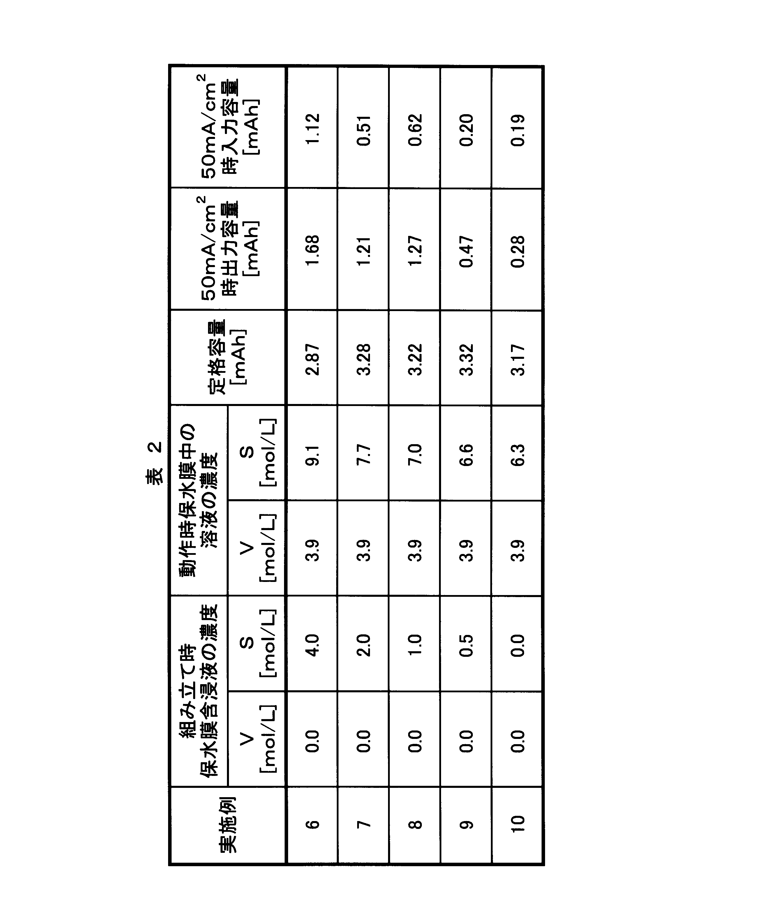
図5より、硫黄濃度が8mol /L以下である場合、50mA/cm2 時の入力容量及び出力容量ともに良好であることが分かる。硫黄濃度は7.8mol /L以下であることがより好ましく、7.5mol /L以下であることがさらに好ましい。
3.保水膜の厚みと電池性能
実施の形態1の構成を有する実施例11~14の各バナジウム固体塩電池1につき、夫々の保水膜55の厚みを下記表3に示すように変えたときの電池性能を評価した。表3に示すように、型番により厚みが異なる。
その結果を下記の表3及び図6に示す。
図6の「50mA/cm2 時充電容量」は開回路電圧(OCV)が1.20Vである状態から電極の面積当たり50mA/cm2 となる電流密度で電流を流して充電した際に、電池の電圧が1.45Vに到達するまで充電が出来たときの電流容量である。「50mA/cm2 時放電容量」は開回路電圧(OCV)が1.45Vである状態から電極の面積当たり50mA/cm2 となる電流密度で電流を流して放電した際に、電池の電圧が1.20Vに到達するまで放電が出来たときの電流容量である。
実施の形態1の構成を有する実施例11~14の各バナジウム固体塩電池1につき、夫々の保水膜55の厚みを下記表3に示すように変えたときの電池性能を評価した。表3に示すように、型番により厚みが異なる。
その結果を下記の表3及び図6に示す。
図6の「50mA/cm2 時充電容量」は開回路電圧(OCV)が1.20Vである状態から電極の面積当たり50mA/cm2 となる電流密度で電流を流して充電した際に、電池の電圧が1.45Vに到達するまで充電が出来たときの電流容量である。「50mA/cm2 時放電容量」は開回路電圧(OCV)が1.45Vである状態から電極の面積当たり50mA/cm2 となる電流密度で電流を流して放電した際に、電池の電圧が1.20Vに到達するまで放電が出来たときの電流容量である。
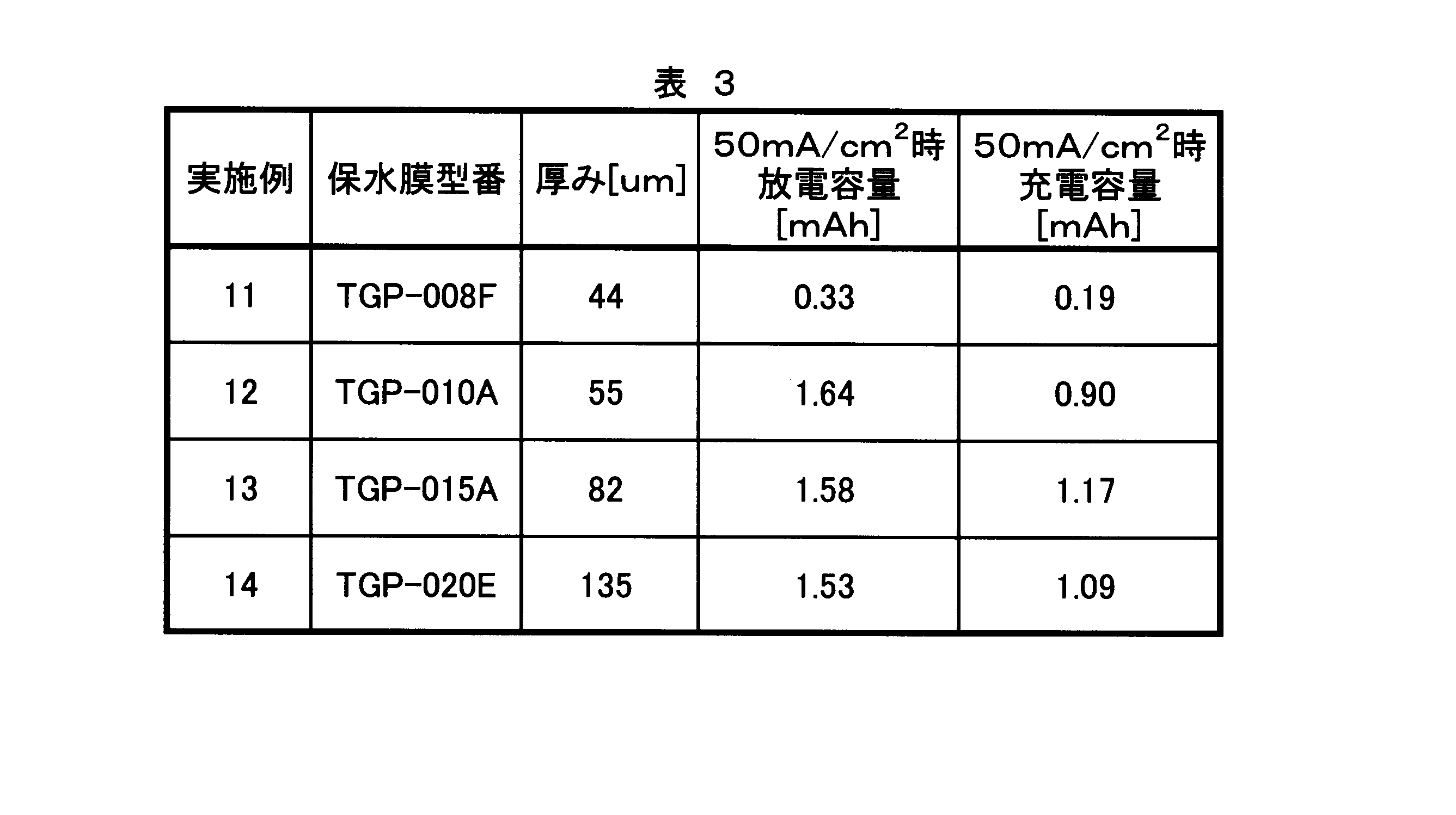
図6より、保水膜55の厚みが50μm以上135μm以下である場合、50mA/cm2 時放電容量及び50mA/cm2 時充電容量ともに良好であることが分かる。厚みの下限は、より好ましくは55μm、さらに好ましくは65μm、特に好ましくは75μmである。
以上より、保水膜55を有するバナジウム固体塩電池1の充放電性能が良好であることが確認された。
本発明に係るバナジウム固体塩電池は、集電体と、正極活物質を含む正極電極とを含む正極であり、前記正極活物質が、酸化還元反応によって、5価及び4価の間で酸化数が変化するバナジウムイオン、又は5価及び4価の間で酸化数が変化するバナジウムを含むイオンを含有するバナジウム固体塩を含む、前記正極と、集電体と、負極活物質を含む負電電極とを含む負極であり、前記負極活物質が、酸化還元反応によって、2価及び3価の間で酸化数が変化するバナジウムイオン、又は2価及び3価の間で酸化数が変化するバナジウムを含むイオンを含有するバナジウム固体塩を含む、前記負極と、水素イオンを通過させ、前記正極電極と前記負極電極との間に設けられたイオン交換膜と、前記イオン交換膜と、前記正極電極又は前記負極電極との間に設けられた保水膜とを備えることを特徴とする。
本発明においては、イオン交換膜と、正極電極又は負極電極との間に保水膜を有するので、イオン交換膜に水分が供給され、イオン交換膜の厚みを薄くした場合に、イオン交換膜のイオン移動に関する抵抗値が増加することが抑制される。
従って、本発明のバナジウム固体塩電池は良好な充放電性能を有し、高い電池容量(出力容量及び入力容量)を有する。
従って、本発明のバナジウム固体塩電池は良好な充放電性能を有し、高い電池容量(出力容量及び入力容量)を有する。
本発明に係るバナジウム固体塩電池は、上述の発明において、前記保水膜の平面面積は、該保水膜が設けられた前記正極電極又は前記負極電極の平面面積以上であることを特徴とする。
本発明においては、電池の使用時にイオン交換膜と電極との間で浸透圧が発生する部分を保水膜によりカバーすることができ、浸透圧の発生時にイオン交換膜中の水分が失われることが抑制される。電極の平面面積の方が保水膜の平面面積より大きい場合、保水膜の水分量が減少する。
本発明に係るバナジウム固体塩電池は、上述のいずれかの発明において、前記保水膜の平面面積は、前記イオン交換膜の平面面積以下であることを特徴とする。
通常、電極の平面面積はイオン交換膜の平面面積より小さく、電池の使用時にイオン交換膜と電極との間で浸透圧が発生する部分を保水膜によりカバーすればよいので、保水膜の平面面積は、イオン交換膜の平面面積以下にする。これにより、保水膜が不要に大きくならず、電池の平面面積が大きくなることが防止される。
本発明に係るバナジウム固体塩電池は、上述のいずれかの発明において、前記保水膜は、多孔質材料からなることを特徴とする。
本発明においては、保水膜の保水性が良好である。
本発明に係るバナジウム固体塩電池は、上述のいずれかの発明において、前記保水膜の厚みは、50μm以上135μm以下であることを特徴とする。
本発明においては、イオン交換膜の薄型化による抵抗値の増加を抑制して、バナジウム固体塩電池の充放電性能を向上させることができるとともに、イオン交換膜と保水膜との合計厚みの増加を抑制して、電池全体の薄型化を図ることができる。
本発明に係るバナジウム固体塩電池は、上述のいずれかの発明において、前記保水膜中のバナジウム元素濃度は、5mol /L以下であり、硫黄元素濃度は、8mol /L以下であることを特徴とする。
本発明においては、バナジウム固体塩電池が良好な充放電性能を有する。
本発明は上述した実施の形態の内容に限定されるものではなく、請求項に示した範囲で種々の変更が可能である。即ち、請求項に示した範囲で適宜変更した技術的手段を組み合わせて得られる実施形態も本発明の技術的範囲に含まれる。
1、11 バナジウム固体塩電池
2 外装袋
3 正極端子
4 負極端子
5、6、7、8、9 電極ユニット
50、60、70、71、80、81、90、91 電極
51、61、72、82、92 導電体
52、62、73、83、93 被覆膜
54、64、74、84、94 シーラント
55、75、95 保水膜
56、85、86 イオン交換膜
2 外装袋
3 正極端子
4 負極端子
5、6、7、8、9 電極ユニット
50、60、70、71、80、81、90、91 電極
51、61、72、82、92 導電体
52、62、73、83、93 被覆膜
54、64、74、84、94 シーラント
55、75、95 保水膜
56、85、86 イオン交換膜
Claims (6)
- 集電体と、正極活物質を含む正極電極とを含む正極であり、前記正極活物質が、酸化還元反応によって、5価及び4価の間で酸化数が変化するバナジウムイオン、又は5価及び4価の間で酸化数が変化するバナジウムを含むイオンを含有するバナジウム固体塩を含む、前記正極と、
集電体と、負極活物質を含む負電電極とを含む負極であり、前記負極活物質が、酸化還元反応によって、2価及び3価の間で酸化数が変化するバナジウムイオン、又は2価及び3価の間で酸化数が変化するバナジウムを含むイオンを含有するバナジウム固体塩を含む、前記負極と、
水素イオンを通過させ、前記正極電極と前記負極電極との間に設けられたイオン交換膜と、
前記イオン交換膜と、前記正極電極又は前記負極電極との間に設けられた保水膜と
を備えることを特徴とするバナジウム固体塩電池。 - 前記保水膜の平面面積は、該保水膜が設けられた前記正極電極又は前記負極電極の平面面積以上であることを特徴とする請求項1に記載のバナジウム固体塩電池。
- 前記保水膜の平面面積は、前記イオン交換膜の平面面積以下であることを特徴とする請求項1又は2に記載のバナジウム固体塩電池。
- 前記保水膜は、多孔質材料からなることを特徴とする請求項1から3までのいずれか1項に記載のバナジウム固体塩電池。
- 前記保水膜の厚みは、50μm以上135μm以下であることを特徴とする請求項1から4までのいずれか1項に記載のバナジウム固体塩電池。
- 前記保水膜中のバナジウム元素濃度は、5mol /L以下であり、硫黄元素濃度は、8mol /L以下であることを特徴とする請求項1から5までのいずれか1項に記載のバナジウム固体塩電池。
Applications Claiming Priority (2)
| Application Number | Priority Date | Filing Date | Title |
|---|---|---|---|
| JP2015066276A JP2016186867A (ja) | 2015-03-27 | 2015-03-27 | バナジウム固体塩電池 |
| JP2015-066276 | 2015-03-27 |
Publications (1)
| Publication Number | Publication Date |
|---|---|
| WO2016158019A1 true WO2016158019A1 (ja) | 2016-10-06 |
Family
ID=57005663
Family Applications (1)
| Application Number | Title | Priority Date | Filing Date |
|---|---|---|---|
| PCT/JP2016/053823 Ceased WO2016158019A1 (ja) | 2015-03-27 | 2016-02-09 | バナジウム固体塩電池 |
Country Status (2)
| Country | Link |
|---|---|
| JP (1) | JP2016186867A (ja) |
| WO (1) | WO2016158019A1 (ja) |
Citations (4)
| Publication number | Priority date | Publication date | Assignee | Title |
|---|---|---|---|---|
| WO2011049103A1 (ja) * | 2009-10-20 | 2011-04-28 | 国立大学法人東北大学 | バナジウム電池 |
| JP2012054035A (ja) * | 2010-08-31 | 2012-03-15 | Tomomi Abe | バナジウムイオン電池 |
| JP2014127428A (ja) * | 2012-12-27 | 2014-07-07 | Tohoku Techno Arch Co Ltd | バナジウムレドックス電池 |
| JP2014235833A (ja) * | 2013-05-31 | 2014-12-15 | 株式会社 東北テクノアーチ | バナジウム固体塩電池 |
-
2015
- 2015-03-27 JP JP2015066276A patent/JP2016186867A/ja active Pending
-
2016
- 2016-02-09 WO PCT/JP2016/053823 patent/WO2016158019A1/ja not_active Ceased
Patent Citations (4)
| Publication number | Priority date | Publication date | Assignee | Title |
|---|---|---|---|---|
| WO2011049103A1 (ja) * | 2009-10-20 | 2011-04-28 | 国立大学法人東北大学 | バナジウム電池 |
| JP2012054035A (ja) * | 2010-08-31 | 2012-03-15 | Tomomi Abe | バナジウムイオン電池 |
| JP2014127428A (ja) * | 2012-12-27 | 2014-07-07 | Tohoku Techno Arch Co Ltd | バナジウムレドックス電池 |
| JP2014235833A (ja) * | 2013-05-31 | 2014-12-15 | 株式会社 東北テクノアーチ | バナジウム固体塩電池 |
Also Published As
| Publication number | Publication date |
|---|---|
| JP2016186867A (ja) | 2016-10-27 |
Similar Documents
| Publication | Publication Date | Title |
|---|---|---|
| KR101387025B1 (ko) | 접촉저항이 개선된 이차전지 | |
| JP5896244B2 (ja) | 腐食防止用保護層を含む電極リードを含む二次電池 | |
| US11018343B1 (en) | Current collector surface treatment | |
| KR20130105578A (ko) | 절연물질이 코팅된 파우치형 2차전지 | |
| WO2016204088A1 (ja) | 電池 | |
| JP2014525658A (ja) | 水分浸透に対する長期信頼性が向上した二次電池 | |
| JP2016186868A (ja) | 電池 | |
| WO2014192358A1 (ja) | バナジウム固体塩電池 | |
| JP2016186865A (ja) | 電池の製造方法及び電池 | |
| JP2016186870A (ja) | 電極ユニット、電池、及び電極ユニットの製造方法 | |
| US20240356184A1 (en) | Pouch Type Secondary Battery, Secondary Battery Module Including the Same, and Pouch for Use Therein | |
| JP2017084732A (ja) | 電極ユニット、電池、及び電池の製造方法 | |
| JP2016186867A (ja) | バナジウム固体塩電池 | |
| JP2016186866A (ja) | 電極ユニットの製造方法 | |
| JP2017084731A (ja) | 電極ユニット、電池及び電極ユニットの製造方法 | |
| JP2016186863A (ja) | 電極ユニット及び電池 | |
| WO2017203921A1 (ja) | バナジウムレドックス二次電池、及びバナジウムレドックス二次電池の製造方法 | |
| JP2016186861A (ja) | 電極ユニット及び電池 | |
| JP2018166092A (ja) | バナジウムレドックス二次電池、隔膜の製造方法、バナジウムレドックス二次電池の製造方法、及び隔膜 | |
| JP2017004794A (ja) | 電極ユニット、電池及び電極ユニットの製造方法 | |
| JP2017183015A (ja) | バナジウム固体塩電池 | |
| JP2018160404A (ja) | バナジウムレドックス二次電池 | |
| JP2016164859A (ja) | バナジウムレドックス電池 | |
| JP2016186860A (ja) | 電池 | |
| JP2017228374A (ja) | 電池セル、電池及び電池セルの製造方法 |
Legal Events
| Date | Code | Title | Description |
|---|---|---|---|
| 121 | Ep: the epo has been informed by wipo that ep was designated in this application |
Ref document number: 16771903 Country of ref document: EP Kind code of ref document: A1 |
|
| NENP | Non-entry into the national phase |
Ref country code: DE |
|
| 122 | Ep: pct application non-entry in european phase |
Ref document number: 16771903 Country of ref document: EP Kind code of ref document: A1 |