WO2016157236A1 - Fluid machine - Google Patents
Fluid machine Download PDFInfo
- Publication number
- WO2016157236A1 WO2016157236A1 PCT/JP2015/001771 JP2015001771W WO2016157236A1 WO 2016157236 A1 WO2016157236 A1 WO 2016157236A1 JP 2015001771 W JP2015001771 W JP 2015001771W WO 2016157236 A1 WO2016157236 A1 WO 2016157236A1
- Authority
- WO
- WIPO (PCT)
- Prior art keywords
- metal case
- fluid
- fluid machine
- sealed container
- positioning locking
- Prior art date
Links
Images


Classifications
-
- F—MECHANICAL ENGINEERING; LIGHTING; HEATING; WEAPONS; BLASTING
- F04—POSITIVE - DISPLACEMENT MACHINES FOR LIQUIDS; PUMPS FOR LIQUIDS OR ELASTIC FLUIDS
- F04B—POSITIVE-DISPLACEMENT MACHINES FOR LIQUIDS; PUMPS
- F04B39/00—Component parts, details, or accessories, of pumps or pumping systems specially adapted for elastic fluids, not otherwise provided for in, or of interest apart from, groups F04B25/00 - F04B37/00
-
- H—ELECTRICITY
- H02—GENERATION; CONVERSION OR DISTRIBUTION OF ELECTRIC POWER
- H02K—DYNAMO-ELECTRIC MACHINES
- H02K5/00—Casings; Enclosures; Supports
- H02K5/04—Casings or enclosures characterised by the shape, form or construction thereof
- H02K5/22—Auxiliary parts of casings not covered by groups H02K5/06-H02K5/20, e.g. shaped to form connection boxes or terminal boxes
Definitions
- the present invention relates to a fluid machine for supplying fluid, such as a compressor and a pump.
- a sealed container having a fluid suction port and a fluid discharge port, and a fluid container that is disposed and driven in the sealed container, sucks fluid into the sealed container from the fluid suction port, and discharges the fluid from the fluid discharge port.
- a compression mechanism an electric motor that is disposed in the sealed container and drives the compression mechanism, an airtight terminal that is welded in a sealed manner to the mounting hole of the sealed container and is connected to the motor by wiring to supply power to the motor from an external power source; What is made up of is known.
- the airtight terminal includes a cup-shaped metal case that is welded in a sealed manner to a mounting hole of the hermetic container, a conductive pin disposed in a burring portion formed on a bottom flat portion of the metal case, and a conductive pin and a burring portion. And a glass seal portion that is loaded in between and holds the conductive pins in an insulating state.
- the burring part of the bottom flat part of the metal case at the hermetic terminal is fixed with a welding jig and pressed against the sealed container with a press. In this state, welding is performed. Since the burring portion is fixed in this manner, excessive stress may be applied to the glass seal portion of the burring portion when the hermetic terminal is pressed and welded to the sealed container. When excessive stress is applied in this way, there is a problem that the glass seal portion is broken, fine cracks are generated, or the insulation resistance is lowered.
- Patent Document 1 a fluid machine has been proposed that includes an airtight terminal in which the thickness of the side wall portion of the metal case is made thinner than the bottom flat surface portion or ribs are formed on the metal case. Yes.
- the stress applied to the insulating glass seal portion is relieved by suppressing the deformation of the metal case of the airtight terminal against the abnormally high pressure in the sealed container.
- Patent Document 1 can prevent the abnormally high pressure in the sealed container by reducing the thickness of the side wall portion of the metal case in the hermetic terminal from the bottom flat surface portion or by forming a rib on the metal case. In this way, deformation of the metal case of the airtight terminal is suppressed and stress relaxation to the glass seal portion is attempted, but deformation at the time of welding to the sealed container is not taken into consideration.
- the present invention has been made to solve the above-described problems, and avoids stress applied to the glass seal portion during welding and prevents misalignment between the airtight terminal and welding jig during welding. Then, it aims at provision of the fluid machine which can ensure sufficient welding length and can improve the reliability of a compressive strength.
- a fluid machine includes a sealed container having a fluid suction port and a fluid discharge port, and a compression mechanism that is disposed and driven in the sealed container to suck fluid from the fluid suction port into the sealed container and discharge the fluid from the fluid discharge port. And an electric motor that is disposed in the sealed container and drives the compression mechanism, and an airtight terminal that is welded in a sealed manner to the mounting hole of the sealed container and is connected to the motor to supply power from the external power source to the motor.
- the hermetic terminal includes a cup-shaped metal case that is welded in a sealed manner to the mounting hole of the hermetic container, a conductive pin disposed in a burring portion formed on a bottom flat portion of the metal case, and a conductive pin and a burring portion. And a glass seal portion that is inserted between and holds the conductive pins in an insulating state, and is inserted into the metal case when the metal case of the hermetic terminal is welded to the mounting hole of the hermetic container.
- a welding jig for positioning and supporting the metal case is used, a first positioning locking portion is provided at the opening edge of the metal case, and the metal case is located at a position facing the opening edge of the metal case in the welding jig.
- a second positioning locking portion that is detachably engaged with the first positioning locking portion is provided.
- the first positioning locking portion is provided at the opening edge of the metal case of the airtight terminal, and the first positioning of the metal case is located at the position where the opening edge of the metal case faces in the welding jig. Since the second positioning locking portion that is detachably engaged with the locking portion is provided, the first positioning locking portion of the opening edge of the metal case is connected to the second of the welding jig during welding. By engaging and fixing the positioning locking portion, the metal case and the welding jig can be accurately positioned at a specified position. Thereby, fixation by the welding jig with respect to the burring part of the bottom plane part of a metal case can be abolished.
- Embodiment 1 of this invention It is a front view of the fluid machine which concerns on Embodiment 1 of this invention. It is a fragmentary longitudinal cross-section which shows the inside of the said fluid machine. It is an expanded sectional view which shows the airtight terminal attachment part of the said fluid machine. It is a side view which shows the metal case of the airtight terminal of the said fluid machine. It is a top view which shows the airtight terminal of the said fluid machine. It is a front view which shows the welding jig used for the said fluid machine. It is a side view of the welding jig. It is a top view which shows the state which mounted
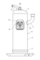
- FIG. 1 is a front view of a fluid machine according to Embodiment 1 of the present invention
- FIG. 2 is a partial longitudinal sectional view showing the inside of the fluid machine
- FIG. 3 is an enlarged sectional view showing an airtight terminal mounting portion of the fluid machine.
- the fluid machine according to the first embodiment is obtained by improving the positioning method during welding of the hermetic terminal.
- a scroll compressor that has an orbiting scroll and is used in a refrigerant circuit such as an air conditioner is exemplified as a fluid machine.
- the scroll compressor as a fluid machine includes a sealed container 14 having a fluid suction port 17A and a fluid discharge port 18A, and a fluid (refrigerant gas) disposed in the sealed container 14 and driven and driven into the sealed container 14 from the fluid suction port 17A.
- a fluid refrigerant gas
- the sealed container 14 is formed in a sealed shape by welding the upper end plate 11 to the upper end edge of the cylindrical container body 12 and welding the lower end plate 13 to the lower end edge of the container body 12.
- a suction pipe 17 is connected to the fluid suction port 17A of the sealed container 14, and a discharge pipe 18 is connected to the fluid discharge port 18A.
- a rotary drive unit such as a rocking scroll in the compression mechanism 15 is connected to a rotary drive shaft 16 ⁇ / b> A of the electric motor 16.
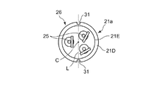
- the airtight terminal 26 includes a cup-shaped metal case 21a that is welded in a sealed manner to the mounting hole 19 of the sealed container 14, and a conductive material disposed in the burring portions 21B, 21B, and 21B formed in the metal case 21a. Attached to the metal case 21 with the pins 25, 25, 25, the insulating glass seal portions 24, 24, 24 loaded between the conductive pins 25 and the burring portions 21 B and holding the conductive pins 25. And a protective hood 23.
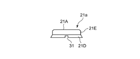
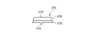
- the metal case 21a includes a flat disk-shaped bottom flat surface portion 21A, an outer surface portion 21E extending from the periphery of the bottom flat surface portion 21A, and a periphery of the outer surface portion 21E.
- An opening edge portion 21D extending in a taper shape and extending.
- the burring portions 21B, 21B, and 21B are formed on the bottom flat surface portion 21A.
- a pair of first positioning locking portions 31 and 31 are provided on the opening edge portion 21D of the metal case 21a. These first positioning locking portions 31, 31 are formed as concave notches, and are provided at opposing positions on a diagonal L passing through the cup cylinder C of the metal case 21a.
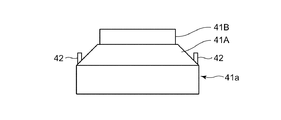
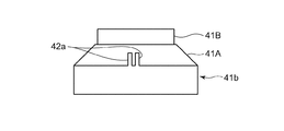
- the welding jig 41a is mounted in the metal case 21a of the hermetic terminal 26, and has a cylindrical shape that supports the back surface of the bottom flat surface portion 21A in the metal case 21a.
- the outer surface portion 41B and a tapered surface portion 41A that extends from the edge of the outer surface portion 41B and supports the back surface of the opening edge portion 21D of the metal case 21a.
- Three pin accommodating spaces 28, 28, 28 for accommodating the respective conductive pins 25 and the glass seal portion 24 are formed on the surface of the outer side surface portion 41B.
- second positioning locking portions 42 and 42 are erected at the position of the tapered surface portion 41A facing the opening edge portion 21D of the mounted metal case 21a.
- These second positioning locking portions 42 and 42 are formed as convex portions, are opposed to each other on a diagonal L passing through the cup cylinder C of the metal case 21a, and the welding jig 41a is in the metal case 21a. It is provided at a position where it engages with the first positioning locking portions 31, 31 of the metal case 21 a when mounted at a specified position for welding.
- the electric motor 16 is supplied with power from an external power source via the hermetic terminal 26 and the electric wire 20. Then, by driving the compression mechanism 15, the refrigerant is sucked into the sealed container 14 from the suction pipe 17 connected to the refrigeration cycle through the fluid suction port 17 ⁇ / b> A and pressurized by the compression mechanism 15, and then the fluid discharge port. It is sent out to the refrigeration cycle from the discharge pipe 18 from 18A.
- the fluid machine is, for example, a refrigerant compressor
- the refrigerant and the refrigerating machine oil circulate in the hermetic container 14.
- the insulating property of the airtight terminal 26 is ensured by applying a silicon coating on the surface to prevent the refrigerant and refrigerator oil from adhering to the surface of the glass seal portion 24.
- the first positioning locking portion 31 of the opening edge 21D of the metal case 21 is replaced with the second positioning locking portion of the welding jig 41 during welding.
- the metal case 21 and the welding jig 41 can be accurately positioned and fixed at the specified positions.
- the fixing by the welding jig 41 of the glass-insulated burring part 21B of the bottom flat part 21A of the metal case 21 as in the prior art can be eliminated.
- the welding length can be stabilized, the quality of the pressure strength of the entire sealed container 14 can be improved.
- the metal case 21a is provided with the concave first positioning locking portions 31 and 31, and the convex second positioning locking portions 42 and 42 engaged therewith are provided on the welding jig 41a.
- the convex first positioning locking portion may be provided on the metal case 21a, and the concave second positioning locking portion that engages with the first positioning locking portion may be provided on the welding jig 41a.
- Embodiment 2 FIG.
- the first positioning locking portions 31 and 31 of the hermetic terminal 26 are provided at positions on the diagonal L passing through the cup cylinder C of the metal case 21a.
- the angles are not two points on the diagonal L. You may form in the position.
- FIGS. Such a second embodiment is shown in FIGS.
- the basic configuration of the airtight terminal 26a and the welding jig 41b according to the second embodiment is the same as that of the airtight terminal 26 and the welding jig 41a shown in the first embodiment.
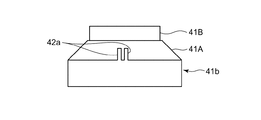
- the place where the airtight terminal 26a and the welding jig 41b according to the second embodiment are different from those of the first embodiment is that the first positioning locking portions 31a and 31a of the metal case 21b in the airtight terminal 26a are Corresponding to being provided at a position (that is, a non-diagonal position) other than on the diagonal line L passing through the cup cylinder C of the metal case 21b as a convex portion, and corresponding to the arrangement of the first positioning locking portions 31a and 31a.
- the second positioning locking portions 42a and 42a are provided as opposing portions at positions other than the diagonal line L passing through the cup cylinder center C of the welding jig 41b as concave portions.
- locking part 42a is the arrangement
- the metal case 21b and the welding jig 41b of the hermetic terminal 26a are provided with concavities and convexities that are engaged for positioning.
- the positioning at the time of welding can be performed not at the glass seal portion 24 and the conductive pin 25 but at the metal case 21b. Therefore, unlike the fluid machine described in Patent Document 1, the fluid machine according to Embodiment 2 can avoid damage to the glass seal portion 24 when welding the airtight terminal 26a to the sealed container 14, As with the first embodiment, the quality of the fluid machine can be improved.
- the fluid machine according to the second embodiment can reliably prevent the reverse phase attachment from being reversed by 180 degrees by the engagement of the concavo-convex portion at the non-diagonal position. For this reason, the fluid machine according to the second embodiment can further improve the quality with respect to the deterioration of the insulation resistance of the terminal portion of the fluid machine as compared with the fluid machine shown in the first embodiment.
- convex first positioning locking portions 31a, 31a are provided on the metal case 21b, and concave positioning second positioning locking portions 42a, 42a, 42a, 42a are formed.
- a concave first positioning locking portion may be provided on the metal case 21b, and a convex second positioning locking portion may be provided on the welding jig 41b.
- the fluid applied to the fluid machine of the present invention is not limited to the refrigerant exemplified in the first and second embodiments, and may be a gas such as air or carbon dioxide, or a liquid such as water or alcohol. .
Landscapes
- Engineering & Computer Science (AREA)
- Mechanical Engineering (AREA)
- General Engineering & Computer Science (AREA)
- Power Engineering (AREA)
- Compressor (AREA)
- Applications Or Details Of Rotary Compressors (AREA)
Abstract
There has been a demand for a fluid machine configured so that a sufficient weld length is ensured between the metallic case of an airtight terminal and a mounting hole in a hermetic container to improve the reliability of strength against pressure. This fluid machine comprises a hermetic container, a compression mechanism, an electric motor, and an airtight terminal (26). A welding jig (41a) which is installed within the metallic case (21a) of the airtight terminal (26) and which positions and supports the metallic case (21a) is used when welding the metallic case (21a) to a mounting hole in the hermetic container. A first positioning engagement section (31) is provided at the opening edge (21D) of the metallic case (21a). A second positioning engagement section (42) which engages with the first positioning engagement section (31) of the metallic case (21a) so as to be capable of disengaging therefrom is provided to the welding jig (41a) at a position facing the opening edge (21D) of the metallic case (21a).
Description
この発明は、例えば圧縮機およびポンプなどのように流体を送給する流体機械に関するものである。
The present invention relates to a fluid machine for supplying fluid, such as a compressor and a pump.
従来、この種の流体機械としては、流体吸入口および流体吐出口を有する密閉容器と、密閉容器内に配備されて駆動し流体吸入口から密閉容器内に流体を吸い込んで流体吐出口から吐出する圧縮機構と、密閉容器内に配備されて圧縮機構を駆動させる電動機と、密閉容器の取付用穴に密封状に溶接され電動機と配線接続されて外部電源を電動機に給電するための気密端子と、から構成されているものが知られている。前記の気密端子は、密閉容器の取付用穴に密封状に溶接されるカップ状の金属ケースと、金属ケースの底平面部に形成されたバーリング部内に配置される導電ピンと、導電ピンとバーリング部の間に装填されて導電ピンを絶縁状に保持するガラスシール部と、を備えている。そうして、気密端子の金属ケースが密閉容器の取付用穴に溶接される際に、金属ケース内に装入されて金属ケースを位置決め支持する溶接治具が用いられるようになっている。
斯かる流体機械は、圧縮機構の駆動により、冷媒が冷凍サイクルから流体吸入口を経て密閉容器内に吸い込まれ、圧縮機構で加圧されたのちに、流体吐出口から冷凍サイクルに戻されるようになっている。 Conventionally, as this type of fluid machine, a sealed container having a fluid suction port and a fluid discharge port, and a fluid container that is disposed and driven in the sealed container, sucks fluid into the sealed container from the fluid suction port, and discharges the fluid from the fluid discharge port. A compression mechanism, an electric motor that is disposed in the sealed container and drives the compression mechanism, an airtight terminal that is welded in a sealed manner to the mounting hole of the sealed container and is connected to the motor by wiring to supply power to the motor from an external power source; What is made up of is known. The airtight terminal includes a cup-shaped metal case that is welded in a sealed manner to a mounting hole of the hermetic container, a conductive pin disposed in a burring portion formed on a bottom flat portion of the metal case, and a conductive pin and a burring portion. And a glass seal portion that is loaded in between and holds the conductive pins in an insulating state. Thus, when the metal case of the hermetic terminal is welded to the mounting hole of the hermetic container, a welding jig that is inserted into the metal case and positions and supports the metal case is used.
In such a fluid machine, by driving the compression mechanism, the refrigerant is sucked into the sealed container from the refrigeration cycle via the fluid suction port, and after being pressurized by the compression mechanism, is returned to the refrigeration cycle from the fluid discharge port. It has become.
上記した従来の流体機械は、気密端子を密閉容器に溶接固着するときに、位置決めとして、気密端子における金属ケースの底平面部のバーリング部を溶接治具で固定して、密閉容器へプレスで押さえつけた状態にして溶接するようになっている。このようにバーリング部を固定しているため、気密端子を密閉容器へプレスして溶接するときにバーリング部のガラスシール部に過大な応力が加わることがある。このように過大な応力が加わると、ガラスシール部が破損したり、または微細なクラックが発生したり、絶縁抵抗が低下したりするという問題があった。また、バーリング部への応力を回避するために、バーリング部と溶接治具とのクリアランスを大きくしようとすると、気密端子と密閉容器との間に位置ずれが生じ、溶接長さがアンバランスとなって溶接力が低下し、耐圧強度が低下してしまうという問題もある。
In the conventional fluid machine described above, when the hermetic terminal is welded and fixed to the sealed container, as a positioning, the burring part of the bottom flat part of the metal case at the hermetic terminal is fixed with a welding jig and pressed against the sealed container with a press. In this state, welding is performed. Since the burring portion is fixed in this manner, excessive stress may be applied to the glass seal portion of the burring portion when the hermetic terminal is pressed and welded to the sealed container. When excessive stress is applied in this way, there is a problem that the glass seal portion is broken, fine cracks are generated, or the insulation resistance is lowered. In addition, in order to avoid stress on the burring part, if an attempt is made to increase the clearance between the burring part and the welding jig, a displacement occurs between the hermetic terminal and the sealed container, and the welding length becomes unbalanced. There is also a problem that the welding force is reduced and the pressure resistance is reduced.
そこで、下記の特許文献1に示すように、金属ケースの側壁部の厚みを底平面部よりも薄く形成したり、または金属ケースにリブを形成したりした気密端子を備える流体機械が提案されている。この特許文献1に記載の技術は、密閉容器内の異常高圧に対して気密端子の金属ケースの変形を抑制することにより、絶縁用のガラスシール部へかかる応力を緩和するようにしている。
Therefore, as shown in Patent Document 1 below, a fluid machine has been proposed that includes an airtight terminal in which the thickness of the side wall portion of the metal case is made thinner than the bottom flat surface portion or ribs are formed on the metal case. Yes. In the technique described in Patent Document 1, the stress applied to the insulating glass seal portion is relieved by suppressing the deformation of the metal case of the airtight terminal against the abnormally high pressure in the sealed container.
ところで、特許文献1記載の技術は、気密端子における金属ケースの側壁部の厚みを底平面部よりも薄くしたり、金属ケースにリブを形成したりすることにより、密閉容器内の異常高圧に対して気密端子の金属ケースの変形を抑制するとともに、ガラスシール部への応力緩和を図るようにしたものであるが、密閉容器への溶接時の変形までは考慮していない。
By the way, the technique described in Patent Document 1 can prevent the abnormally high pressure in the sealed container by reducing the thickness of the side wall portion of the metal case in the hermetic terminal from the bottom flat surface portion or by forming a rib on the metal case. In this way, deformation of the metal case of the airtight terminal is suppressed and stress relaxation to the glass seal portion is attempted, but deformation at the time of welding to the sealed container is not taken into consideration.
この発明は、以上のような課題を解決するためになされたもので、溶接時のガラスシール部にかかる応力を回避するとともに、溶接時の気密端子と溶接治具との位置ずれを防止することで、十分な溶接長さを確保して耐圧強度の信頼性を向上化することのできる流体機械の提供を目的とする。
The present invention has been made to solve the above-described problems, and avoids stress applied to the glass seal portion during welding and prevents misalignment between the airtight terminal and welding jig during welding. Then, it aims at provision of the fluid machine which can ensure sufficient welding length and can improve the reliability of a compressive strength.
この発明に係る流体機械は、流体吸入口および流体吐出口を有する密閉容器と、密閉容器内に配備されて駆動し流体吸入口から密閉容器内に流体を吸い込んで流体吐出口から吐出する圧縮機構と、密閉容器内に配備されて圧縮機構を駆動させる電動機と、密閉容器の取付用穴に密封状に溶接され電動機と配線接続されて外部電源を電動機に給電するための気密端子と、から構成され、気密端子は、密閉容器の取付用穴に密封状に溶接されるカップ状の金属ケースと、金属ケースの底平面部に形成されたバーリング部内に配置される導電ピンと、導電ピンとバーリング部の間に装填されて導電ピンを絶縁状に保持するガラスシール部と、を備えて成り、気密端子の金属ケースが密閉容器の取付用穴に溶接される際に、金属ケース内に装入されて金属ケースを位置決め支持する溶接治具が用いられ、金属ケースの開口縁部には第1位置決め係止部が設けられ、溶接治具において金属ケースの開口縁部と対面する位置には、金属ケースの第1位置決め係止部と係脱可能に係合する第2位置決め係止部が設けられていることを特徴とするものである。
A fluid machine according to the present invention includes a sealed container having a fluid suction port and a fluid discharge port, and a compression mechanism that is disposed and driven in the sealed container to suck fluid from the fluid suction port into the sealed container and discharge the fluid from the fluid discharge port. And an electric motor that is disposed in the sealed container and drives the compression mechanism, and an airtight terminal that is welded in a sealed manner to the mounting hole of the sealed container and is connected to the motor to supply power from the external power source to the motor. The hermetic terminal includes a cup-shaped metal case that is welded in a sealed manner to the mounting hole of the hermetic container, a conductive pin disposed in a burring portion formed on a bottom flat portion of the metal case, and a conductive pin and a burring portion. And a glass seal portion that is inserted between and holds the conductive pins in an insulating state, and is inserted into the metal case when the metal case of the hermetic terminal is welded to the mounting hole of the hermetic container. A welding jig for positioning and supporting the metal case is used, a first positioning locking portion is provided at the opening edge of the metal case, and the metal case is located at a position facing the opening edge of the metal case in the welding jig. A second positioning locking portion that is detachably engaged with the first positioning locking portion is provided.
この発明に係る流体機械は、気密端子の金属ケースの開口縁部に第1位置決め係止部が設けられ、溶接治具において金属ケースの開口縁部が対面する位置に、金属ケースの第1位置決め係止部と係脱可能に係合する第2位置決め係止部が設けられているので、溶接の際に、金属ケースの開口縁部の第1位置決め係止部を、溶接治具の第2位置決め係止部と係合させて固定することにより、金属ケースと溶接治具とを規定位置に正確に位置決めすることができる。それにより、金属ケースの底平面部のバーリング部に対する溶接治具による固定を廃止することができる。その結果、溶接時にかかるガラスシール部への応力を回避することができ、流体機械の製造品質を向上化できる。また、気密端子の金属ケースと密閉容器との間の溶接長さの安定化を図り得るため、密閉容器全体の耐圧強度を向上化できるという効果がある。
In the fluid machine according to the present invention, the first positioning locking portion is provided at the opening edge of the metal case of the airtight terminal, and the first positioning of the metal case is located at the position where the opening edge of the metal case faces in the welding jig. Since the second positioning locking portion that is detachably engaged with the locking portion is provided, the first positioning locking portion of the opening edge of the metal case is connected to the second of the welding jig during welding. By engaging and fixing the positioning locking portion, the metal case and the welding jig can be accurately positioned at a specified position. Thereby, fixation by the welding jig with respect to the burring part of the bottom plane part of a metal case can be abolished. As a result, it is possible to avoid stress on the glass seal portion during welding and improve the manufacturing quality of the fluid machine. Moreover, since the welding length between the metal case of the airtight terminal and the sealed container can be stabilized, there is an effect that the pressure resistance strength of the entire sealed container can be improved.
以下、この発明の実施の形態を図面に基づいて説明する。
実施の形態1.
図1はこの発明の実施の形態1に係る流体機械の正面図、図2は前記流体機械の内部を示す部分縦断面図、図3は前記流体機械の気密端子取付け部分を示す拡大断面図を示している。
図1~図3において、この実施の形態1に係る流体機械は、気密端子の溶接時の位置決め方法に改良が加えられたものである。ここでは、例えば、揺動スクロールを有していて空気調和機などの冷媒回路に用いられるスクロール圧縮機を、流体機械として例示する。 Hereinafter, embodiments of the present invention will be described with reference to the drawings.
Embodiment 1 FIG.
1 is a front view of a fluid machine according to Embodiment 1 of the present invention, FIG. 2 is a partial longitudinal sectional view showing the inside of the fluid machine, and FIG. 3 is an enlarged sectional view showing an airtight terminal mounting portion of the fluid machine. Show.
1 to 3, the fluid machine according to the first embodiment is obtained by improving the positioning method during welding of the hermetic terminal. Here, for example, a scroll compressor that has an orbiting scroll and is used in a refrigerant circuit such as an air conditioner is exemplified as a fluid machine.
この流体機械としてのスクロール圧縮機は、流体吸入口17Aおよび流体吐出口18Aを有する密閉容器14と、密閉容器14内に配備されて駆動し流体吸入口17Aから密閉容器14内に流体(冷媒ガス)を吸い込んで流体吐出口18Aから吐出する圧縮機構15と、密閉容器14内に配備されて圧縮機構15を駆動させる電動機16と、密閉容器14に形成されている取付用穴19に密封状に溶接され電動機16と電線20を介して配線接続されて外部電源を電動機16に給電するための気密端子26と、から構成されている。密閉容器14は、円筒状の容器胴部12の上端縁に上部鏡板11が溶接付けされるとともに、容器胴部12の下端縁に下部鏡板13が溶接付けされて密封状に形成されている。密閉容器14の流体吸入口17Aには吸入管17が接続され、流体吐出口18Aには吐出管18が接続されている。圧縮機構15における揺動スクロールなどの回転駆動部は、電動機16の回転駆動軸16Aと連結されている。
The scroll compressor as a fluid machine includes a sealed container 14 having a fluid suction port 17A and a fluid discharge port 18A, and a fluid (refrigerant gas) disposed in the sealed container 14 and driven and driven into the sealed container 14 from the fluid suction port 17A. ) In the sealed container 14 and the mounting hole 19 formed in the sealed container 14 in a sealed manner. It consists of an airtight terminal 26 that is welded and wired to the electric motor 16 through an electric wire 20 to supply power to the electric motor 16 from an external power source. The sealed container 14 is formed in a sealed shape by welding the upper end plate 11 to the upper end edge of the cylindrical container body 12 and welding the lower end plate 13 to the lower end edge of the container body 12. A suction pipe 17 is connected to the fluid suction port 17A of the sealed container 14, and a discharge pipe 18 is connected to the fluid discharge port 18A. A rotary drive unit such as a rocking scroll in the compression mechanism 15 is connected to a rotary drive shaft 16 </ b> A of the electric motor 16.
前記の気密端子26は、密閉容器14の取付用穴19に密封状に溶接されるカップ状の金属ケース21aと、金属ケース21aに形成されたバーリング部21B,21B,21B内に配置される導電ピン25,25,25と、各導電ピン25と各バーリング部21Bとの間に装填されて各導電ピン25を保持する絶縁用のガラスシール部24,24,24と、金属ケース21に装着される保護用のフード23と、から構成されている。
The airtight terminal 26 includes a cup-shaped metal case 21a that is welded in a sealed manner to the mounting hole 19 of the sealed container 14, and a conductive material disposed in the burring portions 21B, 21B, and 21B formed in the metal case 21a. Attached to the metal case 21 with the pins 25, 25, 25, the insulating glass seal portions 24, 24, 24 loaded between the conductive pins 25 and the burring portions 21 B and holding the conductive pins 25. And a protective hood 23.
そして、図4および図5に示すように、金属ケース21aは、平らな円板状の底平面部21Aと、底平面部21Aの周縁から延在する外側面部21Eと、外側面部21Eの周縁からテーパ状に拡がって延在する開口縁部21Dと、から形成されている。前記のバーリング部21B,21B,21Bは、底平面部21Aに形成されている。金属ケース21aの開口縁部21Dには、1対の第1位置決め係止部31,31が設けられている。これらの第1位置決め係止部31,31は、凹状の切欠きとして形成されており、金属ケース21aのカップ筒心Cを通る対角線L上の対向位置に設けられている。
4 and 5, the metal case 21a includes a flat disk-shaped bottom flat surface portion 21A, an outer surface portion 21E extending from the periphery of the bottom flat surface portion 21A, and a periphery of the outer surface portion 21E. An opening edge portion 21D extending in a taper shape and extending. The burring portions 21B, 21B, and 21B are formed on the bottom flat surface portion 21A. A pair of first positioning locking portions 31 and 31 are provided on the opening edge portion 21D of the metal case 21a. These first positioning locking portions 31, 31 are formed as concave notches, and are provided at opposing positions on a diagonal L passing through the cup cylinder C of the metal case 21a.
一方、図6および図7に示すように、溶接治具41aは、気密端子26の金属ケース21a内に装着されるものであり、金属ケース21a内で底平面部21Aの裏面を支持する円柱状の外側面部41Bと、外側面部41Bの端縁から延在して形成され金属ケース21aの開口縁部21Dの裏面を支持するテーパ面部41Aと、を備えている。外側面部41Bの表面には、各導電ピン25およびガラスシール部24を収容するための3つのピン収容空間28,28,28が形成されている。この溶接治具41aにおいて、装着された金属ケース21aの開口縁部21Dと対面するテーパ面部41Aの位置には、第2位置決め係止部42,42が立設されている。これらの第2位置決め係止部42,42は、凸部として形成されており、金属ケース21aのカップ筒心Cを通る対角線L上の対向位置で、且つ、溶接治具41aが金属ケース21aにおける溶接のための規定位置に装着されたときに金属ケース21aの第1位置決め係止部31,31と係合する位置に設けられている。
On the other hand, as shown in FIGS. 6 and 7, the welding jig 41a is mounted in the metal case 21a of the hermetic terminal 26, and has a cylindrical shape that supports the back surface of the bottom flat surface portion 21A in the metal case 21a. The outer surface portion 41B and a tapered surface portion 41A that extends from the edge of the outer surface portion 41B and supports the back surface of the opening edge portion 21D of the metal case 21a. Three pin accommodating spaces 28, 28, 28 for accommodating the respective conductive pins 25 and the glass seal portion 24 are formed on the surface of the outer side surface portion 41B. In the welding jig 41a, second positioning locking portions 42 and 42 are erected at the position of the tapered surface portion 41A facing the opening edge portion 21D of the mounted metal case 21a. These second positioning locking portions 42 and 42 are formed as convex portions, are opposed to each other on a diagonal L passing through the cup cylinder C of the metal case 21a, and the welding jig 41a is in the metal case 21a. It is provided at a position where it engages with the first positioning locking portions 31, 31 of the metal case 21 a when mounted at a specified position for welding.
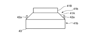
そこで、気密端子26の金属ケース21aがその溶接位置27(図3参照)で密閉容器14の取付用穴19に溶接付けされる際には、図8および図9に示すように、溶接治具41aが金属ケース21a内に装入されて、第2位置決め係止部42,42が、金属ケース21aの第1位置決め係止部31,31と係脱可能に係合し、金属ケース21aを位置決め支持するようになっている。
Therefore, when the metal case 21a of the hermetic terminal 26 is welded to the mounting hole 19 of the sealed container 14 at the welding position 27 (see FIG. 3), as shown in FIGS. 41a is inserted into the metal case 21a, and the second positioning locking portions 42 and 42 are detachably engaged with the first positioning locking portions 31 and 31 of the metal case 21a to position the metal case 21a. It comes to support.
次に動作について説明する。
このように構成された流体機械において、電動機16は気密端子26および電線20を介して外部電源から給電される。そして、圧縮機構15の駆動により、冷凍サイクルにつながっている吸入管17から流体吸入口17Aを経て、冷媒が密閉容器14内に吸い込まれ、圧縮機構15で加圧されたのちに、流体吐出口18Aから吐出管18を経て冷凍サイクルに送り出されるようになっている。ここで、流体機械が例えば冷媒圧縮機などである場合は、密閉容器14内で冷媒や冷凍機油が循環するので、気密端子26の絶縁抵抗を確保するため、気密端子26のガラスシール部24の表面にシリコンコーティングを施すことによりガラスシール部24表面への冷媒や冷凍機油の付着を防止することにより、気密端子26の絶縁性を確保している。 Next, the operation will be described.
In the fluid machine configured as described above, theelectric motor 16 is supplied with power from an external power source via the hermetic terminal 26 and the electric wire 20. Then, by driving the compression mechanism 15, the refrigerant is sucked into the sealed container 14 from the suction pipe 17 connected to the refrigeration cycle through the fluid suction port 17 </ b> A and pressurized by the compression mechanism 15, and then the fluid discharge port. It is sent out to the refrigeration cycle from the discharge pipe 18 from 18A. Here, when the fluid machine is, for example, a refrigerant compressor, the refrigerant and the refrigerating machine oil circulate in the hermetic container 14. Therefore, in order to secure the insulation resistance of the hermetic terminal 26, The insulating property of the airtight terminal 26 is ensured by applying a silicon coating on the surface to prevent the refrigerant and refrigerator oil from adhering to the surface of the glass seal portion 24.
このように構成された流体機械において、電動機16は気密端子26および電線20を介して外部電源から給電される。そして、圧縮機構15の駆動により、冷凍サイクルにつながっている吸入管17から流体吸入口17Aを経て、冷媒が密閉容器14内に吸い込まれ、圧縮機構15で加圧されたのちに、流体吐出口18Aから吐出管18を経て冷凍サイクルに送り出されるようになっている。ここで、流体機械が例えば冷媒圧縮機などである場合は、密閉容器14内で冷媒や冷凍機油が循環するので、気密端子26の絶縁抵抗を確保するため、気密端子26のガラスシール部24の表面にシリコンコーティングを施すことによりガラスシール部24表面への冷媒や冷凍機油の付着を防止することにより、気密端子26の絶縁性を確保している。 Next, the operation will be described.
In the fluid machine configured as described above, the
以上のように、この実施の形態1に係る流体機械は、溶接の際に、金属ケース21の開口縁部21Dの第1位置決め係止部31を、溶接治具41の第2位置決め係止部42と係合させることにより、金属ケース21と溶接治具41とを規定位置に正確に位置決め固定することができる。それにより、従来技術のような金属ケース21の底平面部21Aのガラス絶縁されたバーリング部21Bの溶接治具41による固定を廃止することができる。その結果、溶接時にかかる絶縁用のガラスシール部24への応力を回避することができ、流体機械の製造品質を向上化できる。また、溶接長さの安定化を図ることができるため、密閉容器14全体の耐圧強度の品質を向上化できる。また、この実施の形態1に係る流体機械は、金属ケース21aおよび溶接治具41aの位置決め精度が向上しているため、溶接長さの均等化を図ることができる。これにより、この実施の形態1に係る流体機械は、従来技術のように溶接時に位置決めをしない場合と比べ、溶接長さのアンバランスを回避することができる。
尚、この実施の形態1では、金属ケース21aに凹状の第1位置決め係止部31,31を設け、これらと係合する凸状の第2位置決め係止部42,42を溶接治具41aに設けたが、金属ケース21aに凸状の第1位置決め係止部を設け、これらと係合する凹状の第2位置決め係止部を溶接治具41aに設けてもよい。 As described above, in the fluid machine according to the first embodiment, the firstpositioning locking portion 31 of the opening edge 21D of the metal case 21 is replaced with the second positioning locking portion of the welding jig 41 during welding. By engaging with 42, the metal case 21 and the welding jig 41 can be accurately positioned and fixed at the specified positions. Thereby, the fixing by the welding jig 41 of the glass-insulated burring part 21B of the bottom flat part 21A of the metal case 21 as in the prior art can be eliminated. As a result, it is possible to avoid stress on the insulating glass seal portion 24 during welding and improve the manufacturing quality of the fluid machine. Further, since the welding length can be stabilized, the quality of the pressure strength of the entire sealed container 14 can be improved. In the fluid machine according to the first embodiment, since the positioning accuracy of the metal case 21a and the welding jig 41a is improved, the welding length can be equalized. Thereby, the fluid machine according to the first embodiment can avoid the unbalance of the weld length compared to the case where the positioning is not performed at the time of welding as in the prior art.
In the first embodiment, themetal case 21a is provided with the concave first positioning locking portions 31 and 31, and the convex second positioning locking portions 42 and 42 engaged therewith are provided on the welding jig 41a. Although provided, the convex first positioning locking portion may be provided on the metal case 21a, and the concave second positioning locking portion that engages with the first positioning locking portion may be provided on the welding jig 41a.
尚、この実施の形態1では、金属ケース21aに凹状の第1位置決め係止部31,31を設け、これらと係合する凸状の第2位置決め係止部42,42を溶接治具41aに設けたが、金属ケース21aに凸状の第1位置決め係止部を設け、これらと係合する凹状の第2位置決め係止部を溶接治具41aに設けてもよい。 As described above, in the fluid machine according to the first embodiment, the first
In the first embodiment, the
実施の形態2.
実施の形態1では、気密端子26の第1位置決め係止部31,31を、金属ケース21aのカップ筒心Cを通る対角線L上の位置に設けたが、対角線L上の2点ではない角度の位置に形成してもよい。このような実施の形態2を、図10~図15に示す。
この実施の形態2に係る気密端子26aおよび溶接治具41bの基本的な構成は、実施の形態1で示した気密端子26および溶接治具41aと同様である。そして、この実施の形態2に係る気密端子26aおよび溶接治具41bが実施の形態1のものと構成の異なるところは、気密端子26aにおける金属ケース21bの第1位置決め係止部31a,31aが、凸部として金属ケース21bのカップ筒心Cを通る対角線L上以外の位置(すなわち、非対角の位置)に設けられていることと、第1位置決め係止部31a,31aの配置に対応して、第2位置決め係止部42a,42aが、凹部として溶接治具41bのカップ筒心Cを通る対角線L上以外の対向位置に設けられていることである。各第2位置決め係止部42aは、これらの間が第1位置決め係止部31aを係脱可能に係合させる配置となっている。 Embodiment 2. FIG.
In the first embodiment, the first positioning locking portions 31 and 31 of the hermetic terminal 26 are provided at positions on the diagonal L passing through the cup cylinder C of the metal case 21a. However, the angles are not two points on the diagonal L. You may form in the position. Such a second embodiment is shown in FIGS.
The basic configuration of the airtight terminal 26a and thewelding jig 41b according to the second embodiment is the same as that of the airtight terminal 26 and the welding jig 41a shown in the first embodiment. The place where the airtight terminal 26a and the welding jig 41b according to the second embodiment are different from those of the first embodiment is that the first positioning locking portions 31a and 31a of the metal case 21b in the airtight terminal 26a are Corresponding to being provided at a position (that is, a non-diagonal position) other than on the diagonal line L passing through the cup cylinder C of the metal case 21b as a convex portion, and corresponding to the arrangement of the first positioning locking portions 31a and 31a. Thus, the second positioning locking portions 42a and 42a are provided as opposing portions at positions other than the diagonal line L passing through the cup cylinder center C of the welding jig 41b as concave portions. Each 2nd positioning latching | locking part 42a is the arrangement | positioning which engages the 1st positioning latching | locking part 31a so that engagement / disengagement is possible.
実施の形態1では、気密端子26の第1位置決め係止部31,31を、金属ケース21aのカップ筒心Cを通る対角線L上の位置に設けたが、対角線L上の2点ではない角度の位置に形成してもよい。このような実施の形態2を、図10~図15に示す。
この実施の形態2に係る気密端子26aおよび溶接治具41bの基本的な構成は、実施の形態1で示した気密端子26および溶接治具41aと同様である。そして、この実施の形態2に係る気密端子26aおよび溶接治具41bが実施の形態1のものと構成の異なるところは、気密端子26aにおける金属ケース21bの第1位置決め係止部31a,31aが、凸部として金属ケース21bのカップ筒心Cを通る対角線L上以外の位置(すなわち、非対角の位置)に設けられていることと、第1位置決め係止部31a,31aの配置に対応して、第2位置決め係止部42a,42aが、凹部として溶接治具41bのカップ筒心Cを通る対角線L上以外の対向位置に設けられていることである。各第2位置決め係止部42aは、これらの間が第1位置決め係止部31aを係脱可能に係合させる配置となっている。 Embodiment 2. FIG.
In the first embodiment, the first
The basic configuration of the airtight terminal 26a and the
以上のように、この実施の形態2に係る流体機械は、実施の形態1と同様に、気密端子26aの金属ケース21bと溶接治具41bとに位置決め用に係合する凹凸を設けたことにより、溶接時の位置決めをガラスシール部24および導電ピン25ではなく、金属ケース21bの部位で位置決めできる。そのため、この実施の形態2に係る流体機械は、特許文献1に記載された流体機械とは異なり、気密端子26aを密閉容器14に溶接するときのガラスシール部24へのダメージを回避できるため、実施の形態1と同様に流体機械の品質を向上化することができる。また、この実施の形態2に係る流体機械は、非対角位置での凹凸部の係合により、180度反対向きとなるような逆位相取り付けの防止を確実に行なうことができる。このため、この実施の形態2に係る流体機械は、実施の形態1で示した流体機械と比べ、流体機械の端子部の絶縁抵抗劣化に対する品質をよりいっそう向上化することができる。
As described above, in the fluid machine according to the second embodiment, as in the first embodiment, the metal case 21b and the welding jig 41b of the hermetic terminal 26a are provided with concavities and convexities that are engaged for positioning. The positioning at the time of welding can be performed not at the glass seal portion 24 and the conductive pin 25 but at the metal case 21b. Therefore, unlike the fluid machine described in Patent Document 1, the fluid machine according to Embodiment 2 can avoid damage to the glass seal portion 24 when welding the airtight terminal 26a to the sealed container 14, As with the first embodiment, the quality of the fluid machine can be improved. In addition, the fluid machine according to the second embodiment can reliably prevent the reverse phase attachment from being reversed by 180 degrees by the engagement of the concavo-convex portion at the non-diagonal position. For this reason, the fluid machine according to the second embodiment can further improve the quality with respect to the deterioration of the insulation resistance of the terminal portion of the fluid machine as compared with the fluid machine shown in the first embodiment.
尚、前記の実施の形態2では、金属ケース21bに凸状の第1位置決め係止部31a,31aを設け、これらと係合する凹状を成す第2位置決め係止部42a,42a,42a,42aを溶接治具41bに設けたが、金属ケース21bに凹状の第1位置決め係止部を設け、これらと係合する凸状の第2位置決め係止部を溶接治具41bに設けてもよい。
また、本発明の流体機械に適用される流体としては、実施の形態1,2で例示した冷媒に限らず、空気や炭酸ガスなどの気体、あるいは水やアルコールなどの液体であっても構わない。 In the second embodiment, convex first positioning locking portions 31a, 31a are provided on the metal case 21b, and concave positioning second positioning locking portions 42a, 42a, 42a, 42a are formed. However, a concave first positioning locking portion may be provided on the metal case 21b, and a convex second positioning locking portion may be provided on the welding jig 41b.
The fluid applied to the fluid machine of the present invention is not limited to the refrigerant exemplified in the first and second embodiments, and may be a gas such as air or carbon dioxide, or a liquid such as water or alcohol. .
また、本発明の流体機械に適用される流体としては、実施の形態1,2で例示した冷媒に限らず、空気や炭酸ガスなどの気体、あるいは水やアルコールなどの液体であっても構わない。 In the second embodiment, convex first
The fluid applied to the fluid machine of the present invention is not limited to the refrigerant exemplified in the first and second embodiments, and may be a gas such as air or carbon dioxide, or a liquid such as water or alcohol. .
14 密閉容器
15 圧縮機構
16 電動機
16A 回転駆動軸
17A 流体吸入口
18A 流体吐出口
19 取付用穴
21a,21b 金属ケース
21A 底平面部
21B バーリング部
21D 開口縁部
24 ガラスシール部
25 導電ピン
26,26a 気密端子
31,31a 第1位置決め係止部
41a,41b 溶接治具
41A テーパ面部
42,42a 第2位置決め係止部
C カップ筒心
L 対角線 14 Sealedcontainer 15 Compression mechanism 16 Electric motor 16A Rotation drive shaft 17A Fluid suction port 18A Fluid discharge port 19 Mounting holes 21a and 21b Metal case 21A Bottom flat surface portion 21B Burring portion 21D Opening edge portion 24 Glass seal portion 25 Conductive pins 26 and 26a Airtight terminals 31, 31a First positioning locking portions 41a, 41b Welding jig 41A Tapered surface portions 42, 42a Second positioning locking portions C Cup cylinder L Diagonal line
15 圧縮機構
16 電動機
16A 回転駆動軸
17A 流体吸入口
18A 流体吐出口
19 取付用穴
21a,21b 金属ケース
21A 底平面部
21B バーリング部
21D 開口縁部
24 ガラスシール部
25 導電ピン
26,26a 気密端子
31,31a 第1位置決め係止部
41a,41b 溶接治具
41A テーパ面部
42,42a 第2位置決め係止部
C カップ筒心
L 対角線 14 Sealed
Claims (3)
- 流体吸入口および流体吐出口を有する密閉容器と、前記密閉容器内に配備されて駆動し前記流体吸入口から前記密閉容器内に流体を吸い込んで前記流体吐出口から吐出する圧縮機構と、前記密閉容器内に配備されて前記圧縮機構を駆動させる電動機と、前記密閉容器の取付用穴に密封状に溶接され前記電動機と配線接続されて外部電源を前記電動機に給電するための気密端子と、から構成され、
前記気密端子は、前記密閉容器の取付用穴に密封状に溶接されるカップ状の金属ケースと、前記金属ケースの底平面部に形成されたバーリング部内に配置される導電ピンと、前記導電ピンと前記バーリング部の間に装填されて前記導電ピンを絶縁状に保持するガラスシール部と、を備えて成り、
前記気密端子の金属ケースが前記密閉容器の取付用穴に溶接される際に、前記金属ケース内に装入されて前記金属ケースを位置決め支持する溶接治具が用いられ、
前記金属ケースの開口縁部には第1位置決め係止部が設けられ、前記溶接治具において前記金属ケースの開口縁部と対面する位置には、前記金属ケースの第1位置決め係止部と係脱可能に係合する第2位置決め係止部が設けられていることを特徴とする流体機械。 A sealed container having a fluid suction port and a fluid discharge port; a compression mechanism that is disposed and driven in the sealed container and sucks fluid from the fluid suction port into the sealed container and discharges the fluid from the fluid discharge port; An electric motor arranged in a container for driving the compression mechanism, and an airtight terminal for sealingly welding to the mounting hole of the hermetic container and being connected to the electric motor to feed an external power source to the electric motor; Configured,
The airtight terminal includes a cup-shaped metal case welded in a sealed manner to the mounting hole of the hermetic container, a conductive pin disposed in a burring portion formed on a bottom flat portion of the metal case, the conductive pin, and the A glass seal portion that is loaded between the burring portions and holds the conductive pins in an insulating state.
When the metal case of the hermetic terminal is welded to the mounting hole of the sealed container, a welding jig is used that is inserted into the metal case and supports the positioning of the metal case.
A first positioning locking portion is provided at the opening edge of the metal case, and the first positioning locking portion of the metal case is engaged with the welding jig at a position facing the opening edge of the metal case. A fluid machine characterized in that a second positioning locking portion that is detachably engaged is provided. - 気密端子の金属ケースの第1位置決め係止部が、前記金属ケースのカップ筒心を通る対角線上の位置に設けられていることを特徴とする請求項1に記載の流体機械。 2. The fluid machine according to claim 1, wherein the first positioning locking portion of the metal case of the airtight terminal is provided at a position on a diagonal line passing through the cup cylinder of the metal case.
- 気密端子の金属ケースの第1位置決め係止部が、前記金属ケースのカップ筒心を通る対角線上以外の位置に設けられていることを特徴とする請求項1に記載の流体機械。 2. The fluid machine according to claim 1, wherein the first positioning locking portion of the metal case of the hermetic terminal is provided at a position other than a diagonal line passing through the cup core of the metal case.
Priority Applications (2)
| Application Number | Priority Date | Filing Date | Title |
|---|---|---|---|
| PCT/JP2015/001771 WO2016157236A1 (en) | 2015-03-27 | 2015-03-27 | Fluid machine |
| JP2017508785A JP6366819B2 (en) | 2015-03-27 | 2015-03-27 | Fluid machinery |
Applications Claiming Priority (1)
| Application Number | Priority Date | Filing Date | Title |
|---|---|---|---|
| PCT/JP2015/001771 WO2016157236A1 (en) | 2015-03-27 | 2015-03-27 | Fluid machine |
Publications (1)
| Publication Number | Publication Date |
|---|---|
| WO2016157236A1 true WO2016157236A1 (en) | 2016-10-06 |
Family
ID=57004039
Family Applications (1)
| Application Number | Title | Priority Date | Filing Date |
|---|---|---|---|
| PCT/JP2015/001771 WO2016157236A1 (en) | 2015-03-27 | 2015-03-27 | Fluid machine |
Country Status (2)
| Country | Link |
|---|---|
| JP (1) | JP6366819B2 (en) |
| WO (1) | WO2016157236A1 (en) |
Citations (8)
| Publication number | Priority date | Publication date | Assignee | Title |
|---|---|---|---|---|
| JPH03273844A (en) * | 1990-03-21 | 1991-12-05 | Tecumseh Prod Co | Sealed-up terminal having terminal pin composite piece with fusible link and motor compresser including the same |
| JPH04132885A (en) * | 1990-09-20 | 1992-05-07 | Nec Kansai Ltd | Airtight terminal and compressor |
| JPH11303744A (en) * | 1998-04-20 | 1999-11-02 | Matsushita Electric Ind Co Ltd | Hermetic compressor |
| US20020060217A1 (en) * | 2000-11-23 | 2002-05-23 | Lg Electronics Inc. | Welding apparatus and method thereof for hermetic compressor |
| JP2003148344A (en) * | 2001-11-09 | 2003-05-21 | Mitsubishi Electric Corp | Refrigerant compressor and pressure vessel |
| JP2003161262A (en) * | 2001-11-26 | 2003-06-06 | Sanyo Electric Co Ltd | Compressor |
| JP2005307798A (en) * | 2004-04-20 | 2005-11-04 | Matsushita Electric Ind Co Ltd | Hermetically closed electric compressor |
| US20110008193A1 (en) * | 2009-07-13 | 2011-01-13 | Samsung Gwangju Electronics Co., Ltd. | Hermetic type compressor |
-
2015
- 2015-03-27 WO PCT/JP2015/001771 patent/WO2016157236A1/en active Application Filing
- 2015-03-27 JP JP2017508785A patent/JP6366819B2/en active Active
Patent Citations (8)
| Publication number | Priority date | Publication date | Assignee | Title |
|---|---|---|---|---|
| JPH03273844A (en) * | 1990-03-21 | 1991-12-05 | Tecumseh Prod Co | Sealed-up terminal having terminal pin composite piece with fusible link and motor compresser including the same |
| JPH04132885A (en) * | 1990-09-20 | 1992-05-07 | Nec Kansai Ltd | Airtight terminal and compressor |
| JPH11303744A (en) * | 1998-04-20 | 1999-11-02 | Matsushita Electric Ind Co Ltd | Hermetic compressor |
| US20020060217A1 (en) * | 2000-11-23 | 2002-05-23 | Lg Electronics Inc. | Welding apparatus and method thereof for hermetic compressor |
| JP2003148344A (en) * | 2001-11-09 | 2003-05-21 | Mitsubishi Electric Corp | Refrigerant compressor and pressure vessel |
| JP2003161262A (en) * | 2001-11-26 | 2003-06-06 | Sanyo Electric Co Ltd | Compressor |
| JP2005307798A (en) * | 2004-04-20 | 2005-11-04 | Matsushita Electric Ind Co Ltd | Hermetically closed electric compressor |
| US20110008193A1 (en) * | 2009-07-13 | 2011-01-13 | Samsung Gwangju Electronics Co., Ltd. | Hermetic type compressor |
Also Published As
| Publication number | Publication date |
|---|---|
| JP6366819B2 (en) | 2018-08-01 |
| JPWO2016157236A1 (en) | 2017-10-12 |
Similar Documents
| Publication | Publication Date | Title |
|---|---|---|
| JP6507270B2 (en) | Compressor | |
| JP5109642B2 (en) | Electric compressor | |
| JP4985590B2 (en) | Electric compressor | |
| US10491088B2 (en) | Permanent magnet motor with a rotor having press fitted rivets and press fitted shaft and pin holes and a method for manufacturing the rotor | |
| US20110158833A1 (en) | Electric compressor | |
| JP2007255332A (en) | Compressor | |
| JP2005155369A (en) | Electric compressor | |
| JPWO2018154689A1 (en) | Compressor | |
| WO2016157236A1 (en) | Fluid machine | |
| JP6497365B2 (en) | Pressure vessel, compressor provided with pressure vessel, and method for manufacturing pressure vessel | |
| JP6314610B2 (en) | Compressor welding method | |
| US10495091B2 (en) | Rotary compressor having an injection connecting pipe that extends to an upper portion of a compressor housing and that is linked to an injection pipe via an injection pipe taking-out portion | |
| JP2016142166A (en) | Hermetic type compressor | |
| JP3843917B2 (en) | Compressor and manufacturing method thereof | |
| JP2003148344A (en) | Refrigerant compressor and pressure vessel | |
| WO2020202493A1 (en) | Metal fitting, hermetic-type compressor, and method for manufacturing hermetic-type compressor | |
| JP6391953B2 (en) | Compressor with lower frame and method for manufacturing the same | |
| WO2018138772A1 (en) | Closed-type compressor | |
| JP7312967B2 (en) | Stator, motor and compressor | |
| JP2010101213A (en) | Hermetic compressor and method for manufacturing the same | |
| JP5206635B2 (en) | Electric compressor and manufacturing method thereof | |
| JP2005220762A (en) | Compressor | |
| JP2006070823A (en) | Compressor | |
| JP6076819B2 (en) | Hermetic compressor | |
| JP4395013B2 (en) | Hermetic compressor |
Legal Events
| Date | Code | Title | Description |
|---|---|---|---|
| 121 | Ep: the epo has been informed by wipo that ep was designated in this application |
Ref document number: 15887394 Country of ref document: EP Kind code of ref document: A1 |
|
| ENP | Entry into the national phase |
Ref document number: 2017508785 Country of ref document: JP Kind code of ref document: A |
|
| NENP | Non-entry into the national phase |
Ref country code: DE |
|
| 122 | Ep: pct application non-entry in european phase |
Ref document number: 15887394 Country of ref document: EP Kind code of ref document: A1 |