WO2016153047A1 - 立体物製造装置、立体物製造方法及びプログラム - Google Patents
立体物製造装置、立体物製造方法及びプログラム Download PDFInfo
- Publication number
- WO2016153047A1 WO2016153047A1 PCT/JP2016/059676 JP2016059676W WO2016153047A1 WO 2016153047 A1 WO2016153047 A1 WO 2016153047A1 JP 2016059676 W JP2016059676 W JP 2016059676W WO 2016153047 A1 WO2016153047 A1 WO 2016153047A1
- Authority
- WO
- WIPO (PCT)
- Prior art keywords
- voxel
- dimensional object
- path
- hamilton
- sub
- Prior art date
- Legal status (The legal status is an assumption and is not a legal conclusion. Google has not performed a legal analysis and makes no representation as to the accuracy of the status listed.)
- Ceased
Links
Images





Classifications
-
- B—PERFORMING OPERATIONS; TRANSPORTING
- B29—WORKING OF PLASTICS; WORKING OF SUBSTANCES IN A PLASTIC STATE IN GENERAL
- B29C—SHAPING OR JOINING OF PLASTICS; SHAPING OF MATERIAL IN A PLASTIC STATE, NOT OTHERWISE PROVIDED FOR; AFTER-TREATMENT OF THE SHAPED PRODUCTS, e.g. REPAIRING
- B29C64/00—Additive manufacturing, i.e. manufacturing of three-dimensional [3D] objects by additive deposition, additive agglomeration or additive layering, e.g. by 3D printing, stereolithography or selective laser sintering
- B29C64/30—Auxiliary operations or equipment
- B29C64/386—Data acquisition or data processing for additive manufacturing
-
- B—PERFORMING OPERATIONS; TRANSPORTING
- B33—ADDITIVE MANUFACTURING TECHNOLOGY
- B33Y—ADDITIVE MANUFACTURING, i.e. MANUFACTURING OF THREE-DIMENSIONAL [3D] OBJECTS BY ADDITIVE DEPOSITION, ADDITIVE AGGLOMERATION OR ADDITIVE LAYERING, e.g. BY 3D PRINTING, STEREOLITHOGRAPHY OR SELECTIVE LASER SINTERING
- B33Y50/00—Data acquisition or data processing for additive manufacturing
-
- G—PHYSICS
- G05—CONTROLLING; REGULATING
- G05B—CONTROL OR REGULATING SYSTEMS IN GENERAL; FUNCTIONAL ELEMENTS OF SUCH SYSTEMS; MONITORING OR TESTING ARRANGEMENTS FOR SUCH SYSTEMS OR ELEMENTS
- G05B19/00—Program-control systems
- G05B19/02—Program-control systems electric
- G05B19/18—Numerical control [NC], i.e. automatically operating machines, in particular machine tools, e.g. in a manufacturing environment, so as to execute positioning, movement or co-ordinated operations by means of program data in numerical form
- G05B19/4097—Numerical control [NC], i.e. automatically operating machines, in particular machine tools, e.g. in a manufacturing environment, so as to execute positioning, movement or co-ordinated operations by means of program data in numerical form characterised by using design data to control NC machines, e.g. CAD/CAM
- G05B19/4099—Surface or curve machining, making three-dimensional [3D] objects, e.g. desktop manufacturing
-
- G—PHYSICS
- G05—CONTROLLING; REGULATING
- G05B—CONTROL OR REGULATING SYSTEMS IN GENERAL; FUNCTIONAL ELEMENTS OF SUCH SYSTEMS; MONITORING OR TESTING ARRANGEMENTS FOR SUCH SYSTEMS OR ELEMENTS
- G05B2219/00—Program-control systems
- G05B2219/30—Nc systems
- G05B2219/35—Nc in input of data, input till input file format
- G05B2219/35134—3-D cad-cam
-
- G—PHYSICS
- G05—CONTROLLING; REGULATING
- G05B—CONTROL OR REGULATING SYSTEMS IN GENERAL; FUNCTIONAL ELEMENTS OF SUCH SYSTEMS; MONITORING OR TESTING ARRANGEMENTS FOR SUCH SYSTEMS OR ELEMENTS
- G05B2219/00—Program-control systems
- G05B2219/30—Nc systems
- G05B2219/49—Nc machine tool, till multiple
- G05B2219/49007—Making, forming 3-D object, model, surface
Definitions
- the present invention relates to a three-dimensional object manufacturing apparatus, a three-dimensional object manufacturing method, and a program.
- an STL format that approximates a surface (a surface of a three-dimensional object) with a polygonal mesh is generally adopted as a standard input file format.
- slice data representing the tool path of the 3D printer head is generated from the STL format on CAM (Computer Aided Manufacturing) software.
- CAM Computer Aided Manufacturing
- the shell portion which is the outermost shell and the inside are separated, and for example, for the filling processing inside the modeled object, the pattern prepared in advance in the software such as complete filling, honeycomb structure, etc. Selected from among. This is a contrivance for reducing the amount of material consumption and structurally forming the surface of the modeled object surface.
- Patent Document 1 the technique regarding such 3D printing is described in Patent Document 1, for example.
- the present invention has been made in view of such a conventional situation, and an object of the present invention is to more appropriately generate a tool path for outputting a three-dimensional object in a 3D printer.
- a three-dimensional object manufacturing apparatus of one embodiment of the present invention includes: Voxel model generation means for generating a voxel model representing an internal structure for modeling the three-dimensional object based on three-dimensional shape data representing the shape of the three-dimensional object; Determining means for determining whether a Hamilton path can be set in the voxel model generated by the voxel model generating means; Sub voxel generating means for generating a sub voxel by dividing the voxel in the voxel model when it is determined by the determining means that a Hamilton path cannot be set in the voxel model; Hamilton path setting means for setting a Hamilton path in the voxel model; Tool path generating means for generating a tool path for modeling the modeling material based on the Hamilton path set by the Hamilton path setting means; Based on the tool path generated by the tool path generation unit, a three-dimensional object modeling unit that executes modeling of a three-dimensional object; It
- FIG. 1 is a schematic diagram illustrating a hardware configuration of a three-dimensional object manufacturing apparatus 1 according to an embodiment of the present invention.
- the three-dimensional object manufacturing apparatus 1 includes a three-dimensional object modeling data generation unit 10 and a three-dimensional object modeling unit 20.
- the three-dimensional object formation data generation unit 10 is configured by an information processing apparatus such as a PC (Personal Computer) or an embedded microcomputer.
- the three-dimensional object formation data generation unit 10 is configured by a PC.
- the three-dimensional object formation data generation unit 10 generates slice data representing the tool path of the 3D printer head in the three-dimensional object formation unit 20 from CAD (Computer Aided Sign) data which is design data of the three-dimensional object. At this time, the three-dimensional object formation data generation unit 10 generates a voxel model representing the internal structure of the three-dimensional object from the CAD data, and calculates a Hamilton path for writing the voxel model with a 3D printer head 222 (described later). .
- CAD Computer Aided Sign
- the three-dimensional object formation data generation unit 10 calculates the Hamilton path by generating a sub-voxel obtained by dividing the voxel.
- a single stroke can be written when the voxel is divided into four (for example, refer to the following paper: “Programmable with universal foldable strings (Motains)). ", IEEE TRANSACTIONS ON ROBOTICS, VOL.27, NO.4, AUGUST 2011).
- the three-dimensional object formation data generation unit 10 includes a CPU (Central Processing Unit) 11, a ROM (Read Only Memory) 12, a RAM (Random Access Memory) 13, an input unit 14, and an output unit 15. , A storage unit 16 and a communication unit 17.
- a CPU Central Processing Unit
- ROM Read Only Memory
- RAM Random Access Memory
- the CPU 11 executes various processes according to programs stored in the ROM 12 or the storage unit 16.
- the ROM 12 stores various programs for controlling the three-dimensional object manufacturing apparatus 1.
- the RAM 13 stores data for the CPU 11 to execute various processes.
- the input unit 14 is configured by a pointing device such as a keyboard or a mouse, and inputs various types of information in accordance with user instruction operations.
- the output unit 15 includes a display and a speaker, and displays information and outputs sound according to the control of the CPU 11.
- the storage unit 16 is configured by a storage device such as a hard disk, and stores various data and programs used in the three-dimensional object manufacturing device 1.
- the communication unit 17 communicates with other devices via a communication cable such as a USB (Universal Serial Bus) cable or a communication network such as the Internet.
- a communication cable such as a USB (Universal Serial Bus) cable
- a communication network such as the Internet.
- the three-dimensional object formation data generation unit 10 repeats the search of the tool path until a tool path that matches the set route selection policy is searched, and when a tool path that matches the route selection policy is searched, Control data for controlling the 3D printer head 222 is generated using the tool path.
- the three-dimensional object modeling unit 20 is configured by a 3D printer of a hot melt lamination (FDM) method or an optical modeling method.
- the three-dimensional object modeling unit 20 is assumed to be a hot melt lamination type 3D printer.
- the three-dimensional object modeling unit 20 discharges the modeling material from the 3D printer head 222 while following the Hamilton path, and outputs the three-dimensional object (manufacturing the three-dimensional object).
- the physical size of the voxel drawn by the three-dimensional object modeling unit 20 is determined by adjusting the nozzle diameter of the 3D printer head 222 and the ejection amount of the modeling material.
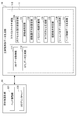
- FIG. 2 is a block diagram illustrating a functional configuration of the three-dimensional object manufacturing apparatus 1.
- the three-dimensional object modeling data generation unit 10 includes a 3D data acquisition unit 111, an STL data generation unit 112, and a slice data generation unit 113.
- the three-dimensional object modeling unit 20 includes a head driving unit 221 and a 3D printer head 222.
- the 3D data acquisition unit 111 acquires CAD data created in the three-dimensional object manufacturing apparatus 1 or CAD data transmitted from another apparatus via a network (not shown). Based on the CAD data acquired by the 3D data acquisition unit 111, the STL data generation unit 112 generates STL data (STL data) that approximates the surface (the surface of the three-dimensional object) with a polygon mesh. The slice data generation unit 113 generates slice data representing the tool path of the 3D printer head 222 based on the STL data generated by the STL data generation unit 112.
- the slice data generation unit 113 includes a start point setting unit 131, a route selection policy setting unit 132, a Hamilton route calculation unit 133, a sub-voxel generation unit 134, a route condition determination unit 135, and tool path data.
- a generation unit 136 and a head control data generation unit 137 are provided.
- the start point setting unit 131 sets the position of the start point at which the 3D printer head 222 starts to discharge the modeling material.
- the start point setting unit 131 sets the position of the start point by accepting designation by the user.
- the path selection policy setting unit 132 sets a policy (path selection policy) for selecting a path through which the 3D printer head 222 discharges the modeling material when modeling a three-dimensional object.
- path selection policy path selection policy
- the direction of the path (the direction along the tool path) through which the 3D printer head 222 ejects the modeling material has a physical property that the tensile / compressive strength is larger, but it is easy to tear.
- the direction in which the path through which the 3D printer head 222 ejects the modeling material is stacked (the direction intersecting the tool path) has a physical characteristic that the tensile / compressive strength is smaller but the tearing is difficult. Therefore, in setting the route selection policy, a policy for selecting the direction of the tool path is set in view of such physical characteristics. For example, a route selection policy such as “the tool path is set in the horizontal direction in the designated area” or “prefer the tensile strength in the designated area” is set.
- the route selection policy setting unit 132 receives the designation of the route selection policy by the user, and sets the route selection policy for an arbitrary region (a part or the whole of the three-dimensional object) of the three-dimensional object. Thereby, the physical characteristic of the three-dimensional object manufactured can be set appropriately.
- the route selection policy it is also possible to arbitrarily select a tool path, select a route that traverses the internal cavity of the three-dimensional structure, or a surface shape with a large inclination (for example, 45 degrees or more) (spread) It is also possible to select a path whose shape is smoother by avoiding a path generated by horizontally slicing a large concave surface, a convex zenith, or the like.
- the Hamilton path calculation unit 133 generates voxel model data representing the internal structure of the three-dimensional structure based on the STL data generated by the STL data generation unit 112. Then, the Hamilton path calculation unit 133 calculates a Hamilton path that follows each voxel in the generated voxel model. At this time, if the Hamilton path calculation unit 133 determines that the Hamilton path that follows each voxel indicated by the voxel model cannot be calculated (that is, each voxel cannot be traced with a single stroke), the Hamilton voxel generation unit 134 , A processing request for dividing a voxel into sub-voxels is output.
- the Hamilton path calculation unit 133 outputs a processing request for dividing all the voxels in the voxel model into sub-voxels when the Hamilton path that follows each voxel indicated by the voxel model cannot be calculated.
- the sub voxel generation unit 134 executes a process of dividing the voxel into sub voxels when a processing request for dividing the voxel into sub voxels is input from the Hamilton path calculation unit 133, and the Hamilton path calculation unit uses the processing result as new voxel data. To 133.
- the sub-voxel generation unit 134 divides all voxels in the voxel model into four (for example, divides the vertical and horizontal directions into two equal parts in a plan view) to obtain sub-voxels.
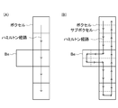
- FIG. 3 is a schematic diagram showing a state in which voxels are divided into sub-voxels.
- FIG. 3A when one voxel Be is branched from the route, it is not possible to write one stroke, so the voxel data cannot set the Hamilton route.
- FIG. 3 (B) by dividing each voxel into four, a branched voxel Be becomes a route that can be circulated.
- the route condition determination unit 135 determines whether the Hamilton route calculated by the Hamilton route calculation unit 133 matches the route selection policy set by the route selection policy setting unit 132.
- the route condition determination unit 135 determines whether the Hamilton route calculated by the Hamilton route calculation unit 133 matches the tool path direction set in the route selection policy. If the path condition determination unit 135 determines that the Hamilton path calculated by the Hamilton path calculation unit 133 does not match the tool path direction set in the path selection policy, the path condition determination unit 135 causes the Hamilton path calculation unit 133 to In contrast, a Hamilton path recalculation request is output. By such processing, one Hamilton route that matches the route selection policy is searched.
- the tool path data generation unit 136 generates slice data representing the tool path of the 3D printer head 222 based on the Hamilton path determined by the path condition determination unit 135 to match the path selection policy.
- the slice data generated by the tool path data generation unit 136 represents a Hamilton path that satisfies the path selection condition and can trace the voxel with a single stroke.
- the head control data generation unit 137 generates control data (head control data) of the 3D printer head 222 for layered modeling of each part of the three-dimensional model based on the slice data generated by the tool path data generation unit 136. To do.
- the 3D printer head 222 can draw a tool path including a component in the vertical direction (the height direction with respect to the stage) in addition to a tool path in the horizontal direction (a direction parallel to the stage). Therefore, the control data of the 3D printer head 222 in the present embodiment can define not only two-dimensional movement in the plane but also three-dimensional movement.
- the head drive unit 221 of the three-dimensional object modeling unit 20 moves the 3D printer head 222 in the horizontal direction and the vertical direction, and discharges the modeling material from the nozzles. And control.
- the 3D printer head 222 discharges the modeling material from the nozzles according to the control of the head driving unit 221.
- the three-dimensional object manufacturing apparatus 1 according to the present embodiment discharges the modeling material while moving the 3D printer head 222 not only in the horizontal direction but also in the vertical direction. Therefore, a cooling fan is installed around the stage, and the modeling is performed. It is good also as accelerating solidification of material.
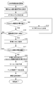
- FIG. 4 is a flowchart for explaining the flow of the three-dimensional object manufacturing process executed by the three-dimensional object manufacturing apparatus 1.
- the three-dimensional object manufacturing process is started in response to an operation instructing the manufacture of a three-dimensional object in the three-dimensional object manufacturing apparatus 1.
- the start point setting unit 131 sets the position of the start point at which the 3D printer head 222 starts to discharge the modeling material.
- the route selection policy setting unit 132 sets a route selection policy.
- the Hamiltonian path calculation unit 133 generates voxel data representing the internal structure of the three-dimensional structure based on the STL data generated by the STL data generation unit 112.
- step S3 the Hamiltonian path calculation unit 133 determines whether or not a Hamiltonian path that follows each voxel can be calculated in the voxel data.
- the generated voxel data when the Hamilton path that follows each voxel cannot be calculated, NO is determined in step S3, and the process proceeds to step S4.
- a processing request for dividing the voxel into sub-voxels is output from the Hamilton path calculation unit 133 to the sub-voxel generation unit 134.
- the generated voxel data when the Hamilton path that follows each voxel can be calculated, YES is determined in step S3, and the process proceeds to step S5.
- step S4 the sub-voxel generation unit 134 executes processing for dividing the voxel into sub-voxels, and outputs the processing result to the Hamiltonian route calculation unit 133 as new voxel data.
- step S ⁇ b> 5 the route condition determining unit 135 determines whether the Hamilton route calculated by the Hamilton route calculating unit 133 matches the route selection policy set by the route selection policy setting unit 132. When the Hamilton route calculated by the Hamilton route calculation unit 133 does not match the route selection policy set by the route selection policy setting unit 132, it is determined as NO in Step S5, and the process proceeds to Step S3. On the other hand, when the Hamiltonian route calculated by the Hamiltonian route calculation unit 133 matches the route selection policy set by the route selection policy setting unit 132, it is determined as YES in Step S5, and the process proceeds to Step S6. To do.
- step S6 the tool path data generation unit 136 generates slice data representing the tool path of the 3D printer head 222 based on the Hamilton path determined by the path condition determination unit 135 to match the path selection policy.
- the head control data generation unit 137 controls the control data (head control) of the 3D printer head 222 for layered modeling of each part of the three-dimensional model based on the slice data generated by the tool path data generation unit 136. Data).
- the head driving unit 221 determines the horizontal and vertical movements of the 3D printer head 222 and the amount of modeling material discharged from the nozzles based on the control data generated by the head control data generation unit 137. Control and execute 3D modeling of the 3D model by the 3D printer head 222.
- step S8 the three-dimensional object manufacturing process ends.
- a Hamilton path that draws a single stroke of a voxel model representing the internal structure of the three-dimensional structure is searched, and a Hamilton path that matches the set path selection policy Is searched, control data for controlling the 3D printer head 222 is generated based on the tool path generated based on the Hamilton path. Therefore, it is possible to generate a tool path for outputting a three-dimensional structure having physical characteristics set in the route selection policy. Therefore, it is possible to generate a tool path for outputting a three-dimensional object in the 3D printer more appropriately.
- the voxel model when searching for the Hamilton path, if the voxel model cannot calculate the Hamilton path, the voxel is divided into sub-voxels. Therefore, since various voxel models can be converted into those for which the Hamilton path can be calculated, it is possible to reliably generate a more appropriate tool path for outputting a three-dimensional object in the 3D printer.
- the three-dimensional object manufacturing apparatus 1 according to the second embodiment includes the same hardware configuration as that of the three-dimensional object manufacturing apparatus 1 according to the first embodiment, but has a different functional configuration and part of the three-dimensional object manufacturing process. Specifically, in the three-dimensional object manufacturing apparatus 1 according to the first embodiment, one Hamilton path that matches the path selection policy is searched. However, in the three-dimensional object manufacturing apparatus 1 according to the second embodiment, All Hamilton routes that match the route selection policy are searched, and the Hamilton route that the user considers optimal can be selected from all the searched Hamilton routes. In the following, parts different from the first embodiment will be mainly described.
- the functional configuration of the three-dimensional object manufacturing apparatus 1 in the second embodiment is a functional configuration other than the Hamilton path calculation unit 133, the sub-voxel generation unit 134, the path condition determination unit 135, and the tool path data generation unit 136 of the slice data generation unit 113. These are the same as the functional configuration of the first embodiment shown in FIG.
- the Hamilton path calculation unit 133 of the slice data generation unit 113 generates voxel data representing the internal structure of the three-dimensional structure based on the STL data generated by the STL data generation unit 112.
- the Hamilton path calculation unit 133 then calculates a Hamilton path that follows each voxel in the generated voxel data.
- the Hamilton path calculation unit 133 determines that the Hamilton path following each voxel indicated by the voxel data cannot be calculated (that is, each voxel cannot be traced with a single stroke)
- the Hamilton voxel generation unit 134 A processing request for dividing a voxel into sub-voxels is output.
- the Hamilton path calculation unit 133 outputs a processing request for dividing all the voxels in the voxel data into sub-voxels.
- the Hamilton path calculation unit 133 determines whether or not all the Hamilton paths that follow each voxel have been searched in the voxel data (whether or not the search for the Hamilton path is continued), and the Hamilton paths that follow each voxel are determined. The search for the Hamiltonian route is repeated until all the searches are completed.
- the sub voxel generation unit 134 executes a process of dividing the voxel into sub voxels when a processing request for dividing the voxel into sub voxels is input from the Hamilton path calculation unit 133, and the Hamilton path calculation unit uses the processing result as new voxel data. To 133.
- the sub-voxel generation unit 134 divides all voxels in the voxel model into four to form sub-voxels.
- the route condition determination unit 135 determines whether the Hamilton route calculated by the Hamilton route calculation unit 133 matches the route selection policy set by the route selection policy setting unit 132. Specifically, the route condition determination unit 135 determines whether the Hamilton route calculated by the Hamilton route calculation unit 133 matches the tool path direction set in the route selection policy. If the path condition determination unit 135 determines that the Hamilton path calculated by the Hamilton path calculation unit 133 does not match the tool path direction set in the path selection policy, the path condition determination unit 135 causes the Hamilton path calculation unit 133 to In contrast, a Hamilton path recalculation request is output.
- the path condition determination unit 135 determines that the Hamilton path calculated by the Hamilton path calculation unit 133 matches the direction of the tool path set in the path selection policy, the path is determined as the Hamilton path. Store in route candidate list. Through such processing, one or more Hamiltonian routes that match the route selection policy are searched.
- the tool path data generation unit 136 accepts selection of the Hamilton path by the user from the Hamilton path candidate list determined by the path condition determination unit 135 to match the path selection policy, and the selected Hamilton path Is read. Then, the tool path data generation unit 136 generates slice data representing the tool path of the 3D printer head 222 based on the Hamilton path selected by the user.
- the slice data generated by the tool path data generation unit 136 represents a path selected by the user among Hamilton paths that satisfy the path selection condition and can trace the voxel with a single stroke.
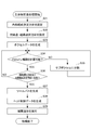
- FIG. 5 is a flowchart illustrating the flow of the three-dimensional object manufacturing process executed by the three-dimensional object manufacturing apparatus 1 according to the second embodiment.
- the processing from step S11 to step S15 is the same as the processing from step S1 to step S5 in FIG.
- step S ⁇ b> 16 the route condition determination unit 135 stores the Hamilton route determined to match the route selection policy in the Hamilton route candidate list.
- step S ⁇ b> 17 the Hamiltonian route calculation unit 133 determines whether to continue searching for the Hamiltonian route in the voxel data (whether the Hamiltonian route that follows each voxel has been finished).
- the search for the Hamilton path is continued (the search for the Hamilton path following each voxel has not been completed), it is determined as YES in Step S17, and the process proceeds to Step S13.
- the search for the Hamiltonian path is not continued in the voxel data (the search for the Hamiltonian path following each voxel has been completed), it is determined as NO in Step S17, and the process proceeds to Step S18.
- step S18 the tool path data generation unit 136 accepts and selects a Hamilton path selected by the user from the Hamilton path candidate list determined by the path condition determination unit 135 to match the path selection policy. Read the Hamiltonian path.
- step S19 the tool path data generation unit 136 generates slice data representing the tool path of the 3D printer head 222 based on the Hamilton path selected by the user. Steps S20 and S21 are the same as steps S7 and S8 in FIG.
- a Hamilton path that draws a single stroke of a voxel model representing the internal structure of the three-dimensional structure is searched, and a Hamilton path that matches the set path selection policy Is searched, the Hamilton path is stored in the Hamilton path candidate list.
- control data for controlling the 3D printer head 222 is generated from the candidate list based on the tool path generated based on the Hamilton path selected by the user. Therefore, a tool path for outputting a three-dimensional structure having physical characteristics set in the route selection policy can be generated in a more adapted manner to the user's desire. Therefore, it is possible to generate a tool path for outputting a three-dimensional object in the 3D printer more appropriately.
- the voxel model when searching for the Hamilton path, if the voxel model cannot calculate the Hamilton path, the voxel is divided into sub-voxels. Therefore, since the voxel data can be converted into one that can calculate the Hamilton path, it is possible to reliably generate a more appropriate tool path for outputting the three-dimensional object in the 3D printer.
- the three-dimensional object manufacturing apparatus 1 according to the third embodiment includes the same hardware configuration as that of the three-dimensional object manufacturing apparatus 1 according to the first embodiment, but has a different functional configuration and part of the three-dimensional object manufacturing process. Specifically, in the three-dimensional object manufacturing apparatus 1 according to the first embodiment, when the Hamilton path that follows each voxel indicated by the voxel model cannot be calculated, all voxels in the voxel model are always divided into sub-voxels. However, in the three-dimensional object manufacturing apparatus 1 according to the third embodiment, only a necessary part in the voxel model can be divided into sub-voxels according to the user's selection. In the following, parts different from the first embodiment will be mainly described.
- FIG. 6 is a block diagram illustrating a functional configuration of the three-dimensional object manufacturing apparatus 1 according to the third embodiment.
- the three-dimensional object modeling data generation unit 10 includes a 3D data acquisition unit 111, an STL data generation unit 112, and a slice data generation unit 113.
- the three-dimensional object modeling unit 20 includes a head driving unit 221 and a 3D printer head 222.
- the functional configuration other than the voxel division policy setting unit 113A, the Hamilton path calculation unit 133, and the sub-voxel generation unit 134 of the slice data generation unit 113 is the same as the functional configuration of the first embodiment shown in FIG. .
- the voxel division policy setting unit 113A of the slice data generation unit 113 sets a policy (voxel division policy) for dividing a voxel into sub-voxels when it is determined that the Hamilton path cannot be calculated.
- a policy for dividing all voxels in the voxel model into sub-voxels or a policy for dividing a portion of voxels in the voxel model where a Hamilton path cannot be calculated into sub-voxels is set.
- the voxel division policy setting unit 113A sets the voxel division policy by accepting the specification of the voxel division policy by the user.
- the voxel division policy setting unit 113A sets the voxel division policy, it is determined that when the three-dimensional object is manufactured, the voxel division policy is set in advance by the user and the Hamilton path cannot be calculated. It is possible to make an inquiry to the user every time and the user sequentially designates and sets the voxel division policy.
- the Hamilton path calculation unit 133 generates voxel model data representing the internal structure of the three-dimensional structure based on the STL data generated by the STL data generation unit 112. Then, the Hamilton path calculation unit 133 calculates a Hamilton path that follows each voxel in the generated voxel model. At this time, if the Hamilton path calculation unit 133 determines that the Hamilton path that follows each voxel indicated by the voxel model cannot be calculated (that is, each voxel cannot be traced with a single stroke), the Hamilton voxel generation unit 134 , A processing request for dividing a voxel into sub-voxels is output.
- the Hamilton path calculation unit 133 is a processing request for dividing all voxels in a voxel model into sub-voxels in accordance with a user policy (voxel division policy) for dividing voxels into sub-voxels, or a part that cannot calculate Hamilton paths in the voxel model
- a user policy voxel division policy
- One of the processing requests for dividing the voxel into sub-voxels is output.
- the sub voxel generation unit 134 executes a process of dividing the voxel into sub voxels when a processing request for dividing the voxel into sub voxels is input from the Hamilton path calculation unit 133, and the Hamilton path calculation unit uses the processing result as new voxel data. To 133.
- the sub-voxel generation unit 134 divides all voxels in the voxel model into four sub-voxels according to the voxel division policy set by the user, or divides a part of voxels that cannot calculate the Hamilton path in the voxel model into four And sub-voxels.
- the Hamilton path can be searched more reliably, and when only the voxel of the part that cannot calculate the Hamilton path in the voxel model is divided into sub-voxels, the efficient Hamilton path is Can be explored.
- FIG. 7 is a flowchart for explaining the flow of the three-dimensional object manufacturing process executed by the three-dimensional object manufacturing apparatus 1 according to the third embodiment.
- the processing from step S21 to step S23 is the same as the processing from step S1 to step S3 in FIG.
- step S24 the Hamilton path calculation unit 133 determines whether a policy for dividing all voxels in the voxel model into sub-voxels is set as the voxel division policy. If the policy for dividing all voxels in the voxel model into sub-voxels is set as the voxel division policy, YES is determined in step S24, and the process proceeds to step S25.
- a voxel division policy a policy is not set to divide all voxels in the voxel model into sub-voxels (that is, a policy is set to divide a voxel in a voxel model where a Hamilton path cannot be calculated into sub-voxels).
- NO is determined in step S24, and the process proceeds to step S26.
- step S25 the sub-voxel generation unit 134 executes a process of dividing all voxels in the voxel model into sub-voxels, and outputs the processing result to the Hamilton path calculation unit 133 as new voxel data.
- step S25 the process proceeds to step S23.
- step S26 the sub-voxel generation unit 134 executes a process of dividing a part of voxels (partial voxels) in which the Hamilton path in the voxel model cannot be calculated into sub-voxels, and uses the processing result as new voxel data to generate the Hamilton path calculation unit 133. Output to.
- step S26 the process proceeds to step S23.
- the processing from step S27 to step S30 is the same as the processing from step S5 to step S8 in FIG.
- a Hamilton path that draws a single stroke of a voxel model representing the internal structure of the three-dimensional structure is searched, and a Hamilton path that matches the set path selection policy Is searched, control data for controlling the 3D printer head 222 is generated based on the tool path generated based on the Hamilton path. Therefore, it is possible to generate a tool path for outputting a three-dimensional structure having physical characteristics set in the route selection policy. Therefore, it is possible to generate a tool path for outputting a three-dimensional object in the 3D printer more appropriately.
- the three-dimensional object manufacturing apparatus 1 when searching for a Hamiltonian path, if the voxel model cannot calculate the Hamiltonian path, all voxels or Hamiltonian paths in the voxel model cannot be calculated according to the voxel division policy. Are divided into sub-voxels. Therefore, all or part of the voxel data can be converted into one that can be calculated by the Hamilton path according to the setting of the user, so that a more appropriate tool path for outputting the three-dimensional object is surely ensured in the 3D printer. Can be generated.
- the three-dimensional object manufacturing apparatus 1 according to the fourth embodiment includes the same hardware configuration as that of the three-dimensional object manufacturing apparatus 1 according to the first embodiment, but has a different functional configuration and part of the three-dimensional object manufacturing process.
- the voxel when the voxel is divided into sub-voxels, all of the sub-voxels belonging to the voxel are filled with the modeling material, but the fourth embodiment
- the internal composition of the voxel when the voxel is divided into sub-voxels, the internal composition of the voxel is changed by filling a part of the sub-voxel belonging to the voxel with a target physical characteristic. Is feasible.
- local or overall optical characteristics transmission, coloring by transmitted light, etc.
- mechanical characteristics softness, hardness, elastic modulus, compression
- Ratio, tensile strength, compressive strength, etc.), acoustic / vibration characteristics, electromagnetic characteristics (conductivity, localization, anisotropy, etc.), and thermal characteristics (heat retention, etc.) can be designed.
- parts different from the first embodiment will be mainly described.
- FIG. 8 is a block diagram illustrating a functional configuration of the three-dimensional object manufacturing apparatus 1 according to the fourth embodiment.
- the slice data generation unit 113 includes an internal composition setting unit 113B, a start point setting unit 131, a route selection policy setting unit 132, a Hamilton route calculation unit 133, A sub-voxel generation unit 134, a path condition determination unit 135, a tool path data generation unit 136, and a head control data generation unit 137 are provided.
- the internal composition setting unit 113B of the slice data generation unit 113 sets a policy (internal composition determination policy) for determining an internal composition when a voxel is divided into sub-voxels.
- the internal composition determination policy can be defined by the filling rate of the sub-voxels inside the voxel, and a condition regarding the filling position of the sub-voxels can be added. For example, when each of the three sides of the vertical, horizontal, and height of the voxel is divided into two, the voxel is divided into eight sub-voxels.
- the filling rate can be set in 9 stages from 0/8 to 8/8 depending on how many of the 8 sub-voxels are filled with the forming material.
- the filling rate softness, transparency, weight, or the like can be set as the physical characteristics of the three-dimensional structure.
- the route condition determination unit 135 matches the Hamilton route calculated by the Hamilton route calculation unit 133 with the route selection policy set by the route selection policy setting unit 132 and the internal composition determination policy set by the internal composition setting unit 113B. It is determined whether or not. Specifically, the path condition determination unit 135 determines whether the Hamilton path calculated by the Hamilton path calculation unit 133 matches the direction of the tool path set in the path selection policy, and the inside of the voxel. It is determined whether or not the conditions related to the sub-voxel filling rate and the sub-voxel filling position are met.
- a Hamilton route recalculation request is output to the Hamilton route calculation unit 133.
- one Hamilton path that matches the path selection policy and the internal composition determination policy is searched.
- the tool path data generation unit 136 generates slice data representing the tool path of the 3D printer head 222 based on the Hamilton path determined by the path condition determination unit 135 to match the path selection policy and the internal composition determination policy. Generate.
- the slice data generated by the tool path data generation unit 136 represents a Hamilton path that satisfies the path selection condition and the internal composition determination policy and can trace voxels with a single stroke.
- the three-dimensional object manufacturing apparatus 1 it is determined which of the voxels divided into the sub-voxels is filled with the modeling material based on the internal composition determination policy. Thereby, a three-dimensional molded item can be manufactured with the internal composition which has a physical characteristic which a user desires.
- FIG. 9 is a flowchart for explaining the flow of the three-dimensional object manufacturing process executed by the three-dimensional object manufacturing apparatus 1 according to the fourth embodiment.
- the internal composition setting unit 113B sets an internal composition determination policy.
- the processing from step S32 to step S35 is the same as the processing from step S1 to step S4 in FIG.
- step S36 the route condition determination unit 135 determines the internal route set by the route selection policy set by the route selection policy setting unit 132 and the internal composition setting unit 113B by the Hamilton route calculated by the Hamilton route calculation unit 133. Judge whether the policy is met. When the Hamiltonian route calculated by the Hamiltonian route calculation unit 133 does not match the route selection policy set by the route selection policy setting unit 132 and the internal composition determination policy set by the internal composition setting unit 113B, in step S36. The determination is NO, and the process proceeds to step S34.
- step In S36 it is determined as YES, and the process proceeds to step S37.
- the processing from step S37 to step S39 is the same as the processing from step S6 to step S8 in FIG.
- a Hamilton path that draws a single stroke of a voxel model representing the internal structure of the three-dimensional structure is searched, and a Hamilton path that matches the set path selection policy Is searched, control data for controlling the 3D printer head 222 is generated based on the tool path generated based on the Hamilton path. Therefore, it is possible to generate a tool path for outputting a three-dimensional structure having physical characteristics set in the route selection policy. Therefore, it is possible to generate a tool path for outputting a three-dimensional object in the 3D printer more appropriately.
- the voxel model when searching for the Hamilton path, if the voxel model cannot calculate the Hamilton path, the voxel is divided into sub-voxels. Therefore, since the voxel data can be converted into one that can calculate the Hamilton path, it is possible to reliably generate a more appropriate tool path for outputting the three-dimensional object in the 3D printer.
- the three-dimensional object manufacturing apparatus 1 when the modeling material is filled in the sub-voxel, a search is made for a Hamilton path that matches the conditions related to the filling rate of the sub-voxel that matches the set internal composition determination policy and the filling position of the sub-voxel.
- Control data for controlling the 3D printer head 222 is generated based on the tool path generated based on the Hamiltonian path. Therefore, it becomes possible to produce a three-dimensional object having desired physical characteristics by changing the internal composition of the voxel.
- voxels or sub-voxels can be filled with two or more types of modeling materials to realize various characteristics of a three-dimensional object.
- a three-dimensional object having various desired characteristics can be manufactured by designating a modeling material to be filled for each voxel or sub-voxel or designating a filling position of the voxel or sub-voxel.
- it is possible to realize the optical characteristics of a three-dimensional object by designating voxels or sub-voxels filled with a modeling material with high transparency and voxels or sub-voxels filled with a modeling material with low transparency.
- voxels or sub-voxels filled with a molding material with high hardness and voxels or sub-voxels filled with a molding material with low hardness mechanical characteristics and acoustic / vibration characteristics related to the flexibility of a three-dimensional object are realized. It becomes possible.
- a voxel or sub-voxel filled with a non-conductive modeling material and a voxel or sub-voxel filled with a conductive modeling material it becomes possible to form an electric circuit inside a three-dimensional object, etc. It becomes possible to realize the electromagnetic characteristics (conductivity, localization, anisotropy, etc.) of the three-dimensional object.
- a three-dimensional object having a sensing function such as sound or temperature sensing
- an active function such as an electrical processing function such as light emission or communication
- the electronic component can be manufactured at the time of modeling in the three-dimensional object manufacturing apparatus 1 by embedding a ready-made one or discharging a conductive filling material.
- the direction of the tool path set in the route selection policy can be set as a priority for selecting the three-axis directions (horizontal and vertical directions) at the branch point of the tool path.
- the priority for selecting the three-axis directions (horizontal and vertical directions) at the branch point of the tool path is set for all voxels or sub-voxels, or some voxels or sub-voxels, and searched. It can be used as an evaluation criterion in determining whether or not the Hamiltonian route matches the route selection policy and in selecting the optimum route from the listed Hamiltonian route.
- the tool path in a predetermined voxel or sub-voxel matches the set priority in the three-axis direction. It is possible to determine the degree as an evaluation criterion. In addition, the degree to which the tool path in a predetermined voxel or sub-voxel in each Hamilton path stored in the candidate list matches the set priority in the three-axis direction is presented as an evaluation criterion for selecting the optimal path, etc. Is possible.
- connectivity with adjacent voxels can be set as a condition regarding the filling position of the sub-voxels set in the internal composition determination policy.
- the ratio of connection in three axial directions (horizontal and vertical directions) (that is, connection anisotropy) can be set as connectivity with adjacent voxels. For example, for all voxels or sub-voxels, or a part of voxels or sub-voxels, a ratio (an index indicating anisotropy or isotropicity) connected in three axial directions (horizontal and vertical directions) is set.
- the tool path in a given voxel or sub-voxel matches the set connection anisotropy when determining whether the searched Hamiltonian path matches the internal composition determination policy. It is possible to determine the degree as an evaluation criterion. In addition, the degree to which the tool path in each predetermined voxel or sub-voxel in each Hamilton path stored in the candidate list matches the set connection anisotropy may be presented as an evaluation criterion for selecting the optimum path, etc. It becomes possible.
- the three-dimensional object manufacturing apparatus 1 configured as described above includes a Hamilton path calculation unit 133, a sub-voxel generation unit 134, a tool path data generation unit 136, and a three-dimensional object formation unit 20.
- the Hamilton path calculation unit 133 generates a voxel model representing the internal structure for modeling the three-dimensional object based on the three-dimensional shape data representing the shape of the three-dimensional object. Further, the Hamilton path calculation unit 133 determines whether or not a Hamilton path can be set in the generated voxel model.
- the sub voxel generation unit 134 divides the voxel in the voxel model and generates a sub voxel.
- the Hamilton path calculation unit 133 sets a Hamilton path in the voxel model.
- the tool path data generation unit 136 generates a tool path for modeling the modeling material based on the Hamilton path set by the Hamilton path calculation unit 133.
- the three-dimensional object modeling unit 20 performs modeling of a three-dimensional object based on the tool path generated by the tool path data generation unit 136.
- a three-dimensional object is formed. Therefore, it is possible to convert various voxel models into those in which a Hamilton path can be set. Therefore, it is possible to generate a tool path for outputting a three-dimensional object in the 3D printer more appropriately.
- the three-dimensional object manufacturing apparatus 1 includes a route selection policy setting unit 132.
- the route selection policy setting unit 132 sets the tool path direction for at least a part of the three-dimensional object.
- the tool path data generation unit 136 sets a tool path based on the direction of the tool path set by the path setting unit. Thereby, the three-dimensional molded item which has a physical characteristic according to the setting regarding the direction of a tool path can be manufactured.
- the tool path data generation unit 136 generates the tool path including a component in a direction along a plane on which a three-dimensional object is formed and a component in a direction perpendicular to the plane. Thereby, it becomes possible to set appropriately the physical characteristic of the solid thing manufactured.
- the sub-voxel generation unit 134 divides all voxels included in the voxel model into sub-voxels. Thereby, the Hamilton path can be searched more reliably.
- the sub-voxel generation unit 134 divides some voxels included in the voxel model into sub-voxels. Thereby, an efficient Hamilton path can be searched.
- the three-dimensional object manufacturing apparatus 1 includes an internal composition setting unit 113B.
- Internal composition setting section 113B sets the internal composition of voxels divided into sub-voxels.
- the tool path data generation unit 136 generates the tool path based on the internal composition of the voxel set by the internal composition setting unit. Thereby, it becomes possible to change the internal composition of the voxel and manufacture a three-dimensional object having the intended physical characteristics.
- the internal composition setting unit 113B sets some sub-voxels that are filled with the modeling material in the voxels. Thereby, the three-dimensional object provided with the various characteristics made into the objective can be manufactured.
- the internal composition setting unit 113B sets the filling rate of the modeling material in the voxel.
- the tool path data generation unit 136 generates a tool path that is one of the combinations of the sub-voxel filling positions with the filling rate set by the internal composition setting unit 113B.
- the internal composition setting unit 113B sets the filling position of the modeling material in the voxel.
- the tool path data generation unit 136 generates a tool path for filling the modeling material into the sub-voxels at the filling position set by the internal composition setting unit 113B.
- the internal composition setting unit 113B sets the internal composition
- the internal composition setting unit 113B sets conditions relating to connectivity with the adjacent voxel.
- route which satisfies the conditions regarding the connectivity with the set adjacent voxel can be set appropriately.
- the three-dimensional object forming unit 20 forms a three-dimensional object by filling voxels or sub-voxels with a plurality of modeling materials. Thereby, the three-dimensional object provided with the various characteristics made into the objective can be manufactured.
- the present invention can be appropriately modified and improved within the scope of the effects of the present invention, and is not limited to the above-described embodiment.
- the size of the three-dimensional object is set within one to several voxels so that the surface and the internal structure are more appropriately connected. It is good also as producing
- this invention combining the said embodiment and each modification suitably.
- the processing in the above-described embodiment can be executed by either hardware or software. That is, it is only necessary that the three-dimensional object manufacturing apparatus 1 has a function capable of executing the above-described processing, and what functional configuration and hardware configuration are used to realize this function is not limited to the above-described example.
- a program constituting the software is installed on a computer from a network or a storage medium.
- the storage medium for storing the program includes a removable medium distributed separately from the apparatus main body, or a storage medium incorporated in the apparatus main body in advance.
- the removable medium is composed of, for example, a magnetic disk, an optical disk, a magneto-optical disk, or the like.
- the optical disk is composed of, for example, a CD-ROM (Compact Disk-Read Only Memory), a DVD (Digital Versatile Disk), a Blu-ray Disc (registered trademark), and the like.
- the magneto-optical disk is constituted by an MD (Mini-Disk) or the like.
- the storage medium incorporated in advance in the apparatus main body is constituted by, for example, a ROM or a hard disk in which a program is stored.
- 1 three-dimensional object manufacturing device 10 three-dimensional object modeling data generation unit, 11 CPU, 12 ROM, 13 RAM, 14 input unit, 15 output unit, 16 storage unit, 17 communication unit, 111 3D data acquisition unit, 112 STL data generation unit , 113 slice data generation unit, 131 start point setting unit, 132 route selection policy setting unit, 133 Hamilton route calculation unit, 134 sub voxel generation unit, 135 route condition determination unit, 136 tool path data generation unit, 137 head control data generation unit 113A voxel division policy setting unit, 113B internal composition setting unit, 20 three-dimensional object modeling unit, 221 head driving unit, 222 3D printer head
Landscapes
- Engineering & Computer Science (AREA)
- Manufacturing & Machinery (AREA)
- Chemical & Material Sciences (AREA)
- Materials Engineering (AREA)
- Physics & Mathematics (AREA)
- Human Computer Interaction (AREA)
- General Physics & Mathematics (AREA)
- Automation & Control Theory (AREA)
- Mechanical Engineering (AREA)
- Optics & Photonics (AREA)
Abstract
3Dプリンタにおいて立体造形物を出力するためのツールパスをより適切に生成すること。 立体物製造装置1において、ハミルトン経路計算部133は、立体物の形状を表す3次元形状データに基づいて、立体物を造形するための内部構造を表すボクセルモデルを生成する。また、ハミルトン経路計算部133は、ボクセルモデルにハミルトン経路を設定できるか否かを判定する。サブボクセル生成部134は、ボクセルモデルにハミルトン経路を設定できないと判定された場合に、ボクセルを分割してサブボクセルを生成する。ハミルトン経路計算部133は、ボクセルモデルにハミルトン経路を設定する。ツールパスデータ生成部136は、設定されたハミルトン経路に基づいて、造形材料を造形するためのツールパスを生成する。立体物造形部20は、ツールパスに基づいて、立体物の造形を実行する。
Description
本発明は、立体物製造装置、立体物製造方法及びプログラムに関する。
従来、立体物を製造する3Dプリンティングシステムにおいては、標準的な入力ファイルフォーマットとして、サーフェス(立体物の表面)を多角形メッシュで近似するSTLフォーマットが一般的に採用されている。また、立体造形出力の際には、CAM(Computer Aided Manufacturing)ソフトウェア上で、STLフォーマットから3Dプリンタヘッドのツールパスを表すスライスデータが生成される。さらに、ツールパスが生成される際、まず最も外殻となるシェル部分と内部とが分離され、例えば造形物内部の充填処理については、完全充填、ハニカム構造等、ソフトウェアに予め用意されたパターンの中から選択される。これは、材料の消費量を少なくして、かつ造形物表面のサーフェスが構造的に成立するための工夫である。
なお、このような3Dプリンティングに関する技術は、例えば特許文献1に記載されている。
なお、このような3Dプリンティングに関する技術は、例えば特許文献1に記載されている。
しかしながら、立体造形物の内部において、空隙を形成したり、素材を合成したりする等、内部構造を有する立体造形物を3Dプリンタで出力する場合、従来のSTLフォーマットやスライスデータの概念にとらわれない新たな観点からツールパスを生成する方法が必要となる。
本発明は、このような従来の実情に鑑みてなされたものであり、3Dプリンタにおいて立体造形物を出力するためのツールパスをより適切に生成することを目的とする。
上記目的を達成するため、本発明の一態様の立体物製造装置は、
立体物の形状を表す3次元形状データに基づいて、前記立体物を造形するための内部構造を表すボクセルモデルを生成するボクセルモデル生成手段と、
前記ボクセルモデル生成手段によって生成されたボクセルモデルにハミルトン経路を設定できるか否かを判定する判定手段と、
前記判定手段によって、前記ボクセルモデルにハミルトン経路を設定できないと判定された場合に、前記ボクセルモデルにおけるボクセルを分割してサブボクセルを生成するサブボクセル生成手段と、
前記ボクセルモデルにハミルトン経路を設定するハミルトン経路設定手段と、
前記ハミルトン経路設定手段によって設定されたハミルトン経路に基づいて、造形材料を造形するためのツールパスを生成するツールパス生成手段と、
前記ツールパス生成手段によって生成されたツールパスに基づいて、立体物の造形を実行する立体物造形手段と、
を備えることを特徴とする。
立体物の形状を表す3次元形状データに基づいて、前記立体物を造形するための内部構造を表すボクセルモデルを生成するボクセルモデル生成手段と、
前記ボクセルモデル生成手段によって生成されたボクセルモデルにハミルトン経路を設定できるか否かを判定する判定手段と、
前記判定手段によって、前記ボクセルモデルにハミルトン経路を設定できないと判定された場合に、前記ボクセルモデルにおけるボクセルを分割してサブボクセルを生成するサブボクセル生成手段と、
前記ボクセルモデルにハミルトン経路を設定するハミルトン経路設定手段と、
前記ハミルトン経路設定手段によって設定されたハミルトン経路に基づいて、造形材料を造形するためのツールパスを生成するツールパス生成手段と、
前記ツールパス生成手段によって生成されたツールパスに基づいて、立体物の造形を実行する立体物造形手段と、
を備えることを特徴とする。
本発明によれば、3Dプリンタにおいて立体造形物を出力するためのツールパスをより適切に生成することができる。
以下、本発明の実施形態について、図面を用いて説明する。
[第1実施形態]
[構成]
図1は、本発明の一実施形態に係る立体物製造装置1のハードウェア構成を示す模式図である。
図1に示すように、立体物製造装置1は、立体物造形データ生成部10と、立体物造形部20とを備えている。
立体物造形データ生成部10は、PC(Personal Computer)や組み込み型のマイコン等の情報処理装置によって構成される。本実施形態においては、立体物造形データ生成部10をPCによって構成するものとする。
[第1実施形態]
[構成]
図1は、本発明の一実施形態に係る立体物製造装置1のハードウェア構成を示す模式図である。
図1に示すように、立体物製造装置1は、立体物造形データ生成部10と、立体物造形部20とを備えている。
立体物造形データ生成部10は、PC(Personal Computer)や組み込み型のマイコン等の情報処理装置によって構成される。本実施形態においては、立体物造形データ生成部10をPCによって構成するものとする。
立体物造形データ生成部10は、立体物の設計データであるCAD(Computer Aided Dsign)データから、立体物造形部20における3Dプリンタヘッドのツールパスを表すスライスデータを生成する。このとき、立体物造形データ生成部10は、CADデータから立体造形物の内部構造を表すボクセルモデルを生成し、ボクセルモデルを3Dプリンタヘッド222(後述)によって一筆書きするためのハミルトン経路を算出する。さらに、ボクセルモデルのハミルトン経路が算出できない(ボクセルモデルが一筆書きできない)場合、立体物造形データ生成部10は、ボクセルを分割したサブボクセルを生成することにより、ハミルトン経路を算出する。なお、ボクセルを一筆書きで辿るハミルトン経路を探索する問題については、ボクセルを4分割すると、必ず一筆書きできることが知られている(例えば、以下の論文参照:“Programmable Assembly With Universally Foldable Strings(Moteins)”,IEEE TRANSACTIONS ON ROBOTICS,VOL.27,NO.4,AUGUST 2011)。
具体的には、立体物造形データ生成部10は、CPU(Central Processing Unit)11と、ROM(Read Only Memory)12と、RAM(Random Access Memory)13と、入力部14と、出力部15と、記憶部16と、通信部17と、を備えている。
CPU11は、ROM12または記憶部16に記憶されたプログラムに従って各種の処理を実行する。
ROM12は、立体物製造装置1を制御するための各種プログラムを記憶する。
RAM13には、CPU11が各種の処理を実行するためのデータ等が記憶される。
ROM12は、立体物製造装置1を制御するための各種プログラムを記憶する。
RAM13には、CPU11が各種の処理を実行するためのデータ等が記憶される。
入力部14は、キーボードあるいはマウス等のポインティングデバイスによって構成され、ユーザの指示操作に応じて各種情報を入力する。
出力部15は、ディスプレイやスピーカによって構成され、CPU11の制御に従って、情報の表示や音声の出力を行う。
記憶部16は、ハードディスク等の記憶装置によって構成され、立体物製造装置1で使用される各種データやプログラムを記憶する。
通信部17は、USB(Universal Serial Bus)ケーブル等の通信ケーブルや、インターネット等の通信ネットワークを介して他の装置との通信を行う。
出力部15は、ディスプレイやスピーカによって構成され、CPU11の制御に従って、情報の表示や音声の出力を行う。
記憶部16は、ハードディスク等の記憶装置によって構成され、立体物製造装置1で使用される各種データやプログラムを記憶する。
通信部17は、USB(Universal Serial Bus)ケーブル等の通信ケーブルや、インターネット等の通信ネットワークを介して他の装置との通信を行う。
また、立体物造形データ生成部10は、設定された経路選択方針に合致するツールパスが探索されるまで、ツールパスの探索を繰り返し、経路選択方針に合致するツールパスが探索されると、そのツールパスを用いて、3Dプリンタヘッド222を制御するための制御データを生成する。
立体物造形部20は、熱溶解積層(FDM:Fused Deposition Modeling)方式あるいは光造形方式の3Dプリンタによって構成される。本実施形態においては、立体物造形部20は、熱溶解積層方式の3Dプリンタであるものとする。立体物造形部20は、立体物造形データ生成部10によって生成された制御データに基づいて、ハミルトン経路を辿りながら3Dプリンタヘッド222から造形材料を吐出し、立体造形物を出力(立体物を製造)する。なお、立体物造形部20が描くボクセルの物理的大きさは、3Dプリンタヘッド222のノズル径と造形材料の吐出量の調節とによって決定される。
[立体物製造装置1の機能的構成]
次に、立体物製造装置1の機能的構成について説明する。
図2は、立体物製造装置1の機能的構成を示すブロック図である。
図2に示すように、立体物製造装置1において、立体物造形データ生成部10は、3Dデータ取得部111と、STLデータ生成部112と、スライスデータ生成部113とを備えている。また、立体物造形部20は、ヘッド駆動部221と、3Dプリンタヘッド222とを備えている。
次に、立体物製造装置1の機能的構成について説明する。
図2は、立体物製造装置1の機能的構成を示すブロック図である。
図2に示すように、立体物製造装置1において、立体物造形データ生成部10は、3Dデータ取得部111と、STLデータ生成部112と、スライスデータ生成部113とを備えている。また、立体物造形部20は、ヘッド駆動部221と、3Dプリンタヘッド222とを備えている。
3Dデータ取得部111は、立体物製造装置1において作成されたCADデータあるいは不図示のネットワーク等を介して他の装置から送信されたCADデータを取得する。
STLデータ生成部112は、3Dデータ取得部111によって取得されたCADデータに基づいて、サーフェス(立体物の表面)を多角形メッシュで近似するSTL形式のデータ(STLデータ)を生成する。
スライスデータ生成部113は、STLデータ生成部112によって生成されたSTLデータに基づいて、3Dプリンタヘッド222のツールパスを表すスライスデータを生成する。
具体的には、スライスデータ生成部113は、開始点設定部131と、経路選択方針設定部132と、ハミルトン経路計算部133と、サブボクセル生成部134と、経路条件判定部135と、ツールパスデータ生成部136と、ヘッド制御データ生成部137とを備えている。
STLデータ生成部112は、3Dデータ取得部111によって取得されたCADデータに基づいて、サーフェス(立体物の表面)を多角形メッシュで近似するSTL形式のデータ(STLデータ)を生成する。
スライスデータ生成部113は、STLデータ生成部112によって生成されたSTLデータに基づいて、3Dプリンタヘッド222のツールパスを表すスライスデータを生成する。
具体的には、スライスデータ生成部113は、開始点設定部131と、経路選択方針設定部132と、ハミルトン経路計算部133と、サブボクセル生成部134と、経路条件判定部135と、ツールパスデータ生成部136と、ヘッド制御データ生成部137とを備えている。
開始点設定部131は、3Dプリンタヘッド222が造形材料の吐出を開始する開始点の位置を設定する。本実施形態において、開始点設定部131は、ユーザによる指定を受け付けることにより、開始点の位置を設定する。
経路選択方針設定部132は、立体物を造形する際に、3Dプリンタヘッド222が造形材料を吐出する経路を選択する方針(経路選択方針)を設定する。ここで、立体物を造形する場合、同一のSTLデータによって表されるものであっても、3Dプリンタヘッド222がどのような経路によって造形材料を吐出するか(即ち、どのようなツールパスを辿るか)によって、立体造形物の物理的特性が異なるものとなる。
経路選択方針設定部132は、立体物を造形する際に、3Dプリンタヘッド222が造形材料を吐出する経路を選択する方針(経路選択方針)を設定する。ここで、立体物を造形する場合、同一のSTLデータによって表されるものであっても、3Dプリンタヘッド222がどのような経路によって造形材料を吐出するか(即ち、どのようなツールパスを辿るか)によって、立体造形物の物理的特性が異なるものとなる。
具体的には、3Dプリンタヘッド222が造形材料を吐出した経路の方向(ツールパスに沿う方向)については、引張り・圧縮強度がより大きい一方、裂け易いという物理的特性を有する。また、3Dプリンタヘッド222が造形材料を吐出した経路が積層する方向(ツールパスと交差する方向)については、引張り・圧縮強度がより小さい一方、裂け難いという物理的特性を有する。したがって、経路選択方針の設定においては、このような物理的特性に鑑みて、ツールパスの方向を選択する方針が設定される。例えば、「指定された領域においては、ツールパスを水平方向とする」あるいは「指定された領域においては、引張り強度を優先する」といった経路選択方針が設定される。本実施形態において、経路選択方針設定部132は、ユーザによる経路選択方針の指定を受け付けることにより、立体造形物の任意の領域(立体物の一部または全体)について、経路選択方針を設定する。これにより、製造される立体物の物理的特性を適切に設定することができる。
なお、経路選択方針の設定においては、ツールパスを任意に選択することも可能であり、立体造形物の内部空洞を横切る経路を選択したり、大きい傾斜(例えば45度以上)の表面形状(広がりの大きい凹面、凸面の天頂等)が水平方向にスライスされて生じる経路を回避し、形状がより滑らかになる経路を選択したりすることもできる。
なお、経路選択方針の設定においては、ツールパスを任意に選択することも可能であり、立体造形物の内部空洞を横切る経路を選択したり、大きい傾斜(例えば45度以上)の表面形状(広がりの大きい凹面、凸面の天頂等)が水平方向にスライスされて生じる経路を回避し、形状がより滑らかになる経路を選択したりすることもできる。
ハミルトン経路計算部133は、STLデータ生成部112によって生成されたSTLデータに基づいて、立体造形物の内部構造を表すボクセルモデルのデータを生成する。そして、ハミルトン経路計算部133は、生成したボクセルモデルにおいて、各ボクセルを辿るハミルトン経路を計算する。このとき、ハミルトン経路計算部133は、ボクセルモデルによって示される各ボクセルを辿るハミルトン経路を計算できない(即ち、各ボクセルを一筆書きで辿ることができない)と判定した場合、サブボクセル生成部134に対して、ボクセルをサブボクセルに分割する処理要求を出力する。本実施形態において、ハミルトン経路計算部133は、ボクセルモデルによって示される各ボクセルを辿るハミルトン経路を計算できない場合、ボクセルモデルにおける全てのボクセルをサブボクセルに分割する処理要求を出力する。
サブボクセル生成部134は、ハミルトン経路計算部133からボクセルをサブボクセルに分割する処理要求が入力された場合に、ボクセルをサブボクセルに分割する処理を実行し、処理結果を新たなボクセルデータとしてハミルトン経路計算部133に出力する。本実施形態において、サブボクセル生成部134は、ボクセルモデルにおける全てのボクセルを4分割して(例えば、平面視において縦横を2等分して)サブボクセルとする。
図3は、ボクセルをサブボクセルに分割した状態を示す模式図である。
図3(A)に示すように、1つのボクセルBeが経路から分岐している場合、一筆書きすることができないことから、ハミルトン経路が設定できないボクセルデータとなる。
このとき、図3(B)に示すように、各ボクセルを4分割することにより、分岐していたボクセルBeが周回可能な経路となる。
図2に戻り、経路条件判定部135は、ハミルトン経路計算部133によって計算されたハミルトン経路が、経路選択方針設定部132によって設定された経路選択方針に合致しているか否かの判定を行う。具体的には、経路条件判定部135は、ハミルトン経路計算部133によって計算されたハミルトン経路が、経路選択方針において設定されているツールパスの方向と合致しているか否かの判定を行う。そして、経路条件判定部135は、ハミルトン経路計算部133によって計算されたハミルトン経路が、経路選択方針において設定されているツールパスの方向と合致していないと判定した場合、ハミルトン経路計算部133に対し、ハミルトン経路の再計算要求を出力する。このような処理によって、経路選択方針に合致するハミルトン経路が1つ探索される。
図3(A)に示すように、1つのボクセルBeが経路から分岐している場合、一筆書きすることができないことから、ハミルトン経路が設定できないボクセルデータとなる。
このとき、図3(B)に示すように、各ボクセルを4分割することにより、分岐していたボクセルBeが周回可能な経路となる。
図2に戻り、経路条件判定部135は、ハミルトン経路計算部133によって計算されたハミルトン経路が、経路選択方針設定部132によって設定された経路選択方針に合致しているか否かの判定を行う。具体的には、経路条件判定部135は、ハミルトン経路計算部133によって計算されたハミルトン経路が、経路選択方針において設定されているツールパスの方向と合致しているか否かの判定を行う。そして、経路条件判定部135は、ハミルトン経路計算部133によって計算されたハミルトン経路が、経路選択方針において設定されているツールパスの方向と合致していないと判定した場合、ハミルトン経路計算部133に対し、ハミルトン経路の再計算要求を出力する。このような処理によって、経路選択方針に合致するハミルトン経路が1つ探索される。
ツールパスデータ生成部136は、経路条件判定部135によって、経路選択方針に合致していると判定されたハミルトン経路に基づいて、3Dプリンタヘッド222のツールパスを表すスライスデータを生成する。ツールパスデータ生成部136によって生成されたスライスデータは、経路選択条件を充足し、ボクセルを一筆書きで辿ることが可能なハミルトン経路を表すものとなる。
ヘッド制御データ生成部137は、ツールパスデータ生成部136によって生成されたスライスデータに基づいて、立体造形物の各部分を積層造形するための3Dプリンタヘッド222の制御データ(ヘッド制御データ)を生成する。本実施形態において、3Dプリンタヘッド222は、水平方向(ステージと平行な方向)のツールパスの他、垂直方向(ステージに対する高さ方向)の成分を含むツールパスを描くことが可能である。したがって、本実施形態における3Dプリンタヘッド222の制御データは、平面内における2次元の移動のみならず、3次元の移動を規定することが可能である。
ヘッド制御データ生成部137は、ツールパスデータ生成部136によって生成されたスライスデータに基づいて、立体造形物の各部分を積層造形するための3Dプリンタヘッド222の制御データ(ヘッド制御データ)を生成する。本実施形態において、3Dプリンタヘッド222は、水平方向(ステージと平行な方向)のツールパスの他、垂直方向(ステージに対する高さ方向)の成分を含むツールパスを描くことが可能である。したがって、本実施形態における3Dプリンタヘッド222の制御データは、平面内における2次元の移動のみならず、3次元の移動を規定することが可能である。
立体物造形部20のヘッド駆動部221は、ヘッド制御データ生成部137によって生成された制御データに基づいて、3Dプリンタヘッド222の水平方向及び垂直方向の移動と、ノズルからの造形材料の吐出量とを制御する。
3Dプリンタヘッド222は、ヘッド駆動部221の制御に従って、ノズルから造形材料を吐出する。
本実施形態における立体物製造装置1は、水平方向のみならず、垂直方向にも3Dプリンタヘッド222を移動させながら造形材料を吐出することから、ステージの周囲に冷却用のファンを設置し、造形材料の固化を早めることとしてもよい。
3Dプリンタヘッド222は、ヘッド駆動部221の制御に従って、ノズルから造形材料を吐出する。
本実施形態における立体物製造装置1は、水平方向のみならず、垂直方向にも3Dプリンタヘッド222を移動させながら造形材料を吐出することから、ステージの周囲に冷却用のファンを設置し、造形材料の固化を早めることとしてもよい。
[動作]
次に、立体物製造装置1の動作を説明する。
図4は、立体物製造装置1が実行する立体物製造処理の流れを説明するフローチャートである。
立体物製造処理は、立体物製造装置1において、立体物の製造を指示する操作が行われることに対応して開始される。
ステップS1において、開始点設定部131は、3Dプリンタヘッド222が造形材料の吐出を開始する開始点の位置を設定する。また、経路選択方針設定部132は、経路選択方針を設定する。
ステップS2において、ハミルトン経路計算部133は、STLデータ生成部112によって生成されたSTLデータに基づいて、立体造形物の内部構造を表すボクセルデータを生成する。
次に、立体物製造装置1の動作を説明する。
図4は、立体物製造装置1が実行する立体物製造処理の流れを説明するフローチャートである。
立体物製造処理は、立体物製造装置1において、立体物の製造を指示する操作が行われることに対応して開始される。
ステップS1において、開始点設定部131は、3Dプリンタヘッド222が造形材料の吐出を開始する開始点の位置を設定する。また、経路選択方針設定部132は、経路選択方針を設定する。
ステップS2において、ハミルトン経路計算部133は、STLデータ生成部112によって生成されたSTLデータに基づいて、立体造形物の内部構造を表すボクセルデータを生成する。
ステップS3において、ハミルトン経路計算部133は、ボクセルデータにおいて、各ボクセルを辿るハミルトン経路を計算できるか否かの判定を行う。
生成したボクセルデータにおいて、各ボクセルを辿るハミルトン経路を計算できない場合、ステップS3においてNOと判定されて、処理はステップS4に移行する。このとき、ハミルトン経路計算部133からサブボクセル生成部134に対して、ボクセルをサブボクセルに分割する処理要求が出力される。
一方、生成したボクセルデータにおいて、各ボクセルを辿るハミルトン経路を計算できる場合、ステップS3においてYESと判定されて、処理はステップS5に移行する。
生成したボクセルデータにおいて、各ボクセルを辿るハミルトン経路を計算できない場合、ステップS3においてNOと判定されて、処理はステップS4に移行する。このとき、ハミルトン経路計算部133からサブボクセル生成部134に対して、ボクセルをサブボクセルに分割する処理要求が出力される。
一方、生成したボクセルデータにおいて、各ボクセルを辿るハミルトン経路を計算できる場合、ステップS3においてYESと判定されて、処理はステップS5に移行する。
ステップS4において、サブボクセル生成部134は、ボクセルをサブボクセルに分割する処理を実行し、処理結果を新たなボクセルデータとしてハミルトン経路計算部133に出力する。
ステップS4の後、処理はステップS3に移行する。
ステップS5において、経路条件判定部135は、ハミルトン経路計算部133によって計算されたハミルトン経路が、経路選択方針設定部132によって設定された経路選択方針に合致しているか否かの判定を行う。
ハミルトン経路計算部133によって計算されたハミルトン経路が、経路選択方針設定部132によって設定された経路選択方針に合致していない場合、ステップS5においてNOと判定されて、処理はステップS3に移行する。
一方、ハミルトン経路計算部133によって計算されたハミルトン経路が、経路選択方針設定部132によって設定された経路選択方針に合致している場合、ステップS5においてYESと判定されて、処理はステップS6に移行する。
ステップS4の後、処理はステップS3に移行する。
ステップS5において、経路条件判定部135は、ハミルトン経路計算部133によって計算されたハミルトン経路が、経路選択方針設定部132によって設定された経路選択方針に合致しているか否かの判定を行う。
ハミルトン経路計算部133によって計算されたハミルトン経路が、経路選択方針設定部132によって設定された経路選択方針に合致していない場合、ステップS5においてNOと判定されて、処理はステップS3に移行する。
一方、ハミルトン経路計算部133によって計算されたハミルトン経路が、経路選択方針設定部132によって設定された経路選択方針に合致している場合、ステップS5においてYESと判定されて、処理はステップS6に移行する。
ステップS6において、ツールパスデータ生成部136は、経路条件判定部135によって、経路選択方針に合致していると判定されたハミルトン経路に基づいて、3Dプリンタヘッド222のツールパスを表すスライスデータを生成する。
ステップS7において、ヘッド制御データ生成部137は、ツールパスデータ生成部136によって生成されたスライスデータに基づいて、立体造形物の各部分を積層造形するための3Dプリンタヘッド222の制御データ(ヘッド制御データ)を生成する。
ステップS8において、ヘッド駆動部221は、ヘッド制御データ生成部137によって生成された制御データに基づいて、3Dプリンタヘッド222の水平方向及び垂直方向の移動と、ノズルからの造形材料の吐出量とを制御し、3Dプリンタヘッド222による立体造形物の積層造形を実行する。
ステップS8の後、立体物製造処理は終了となる。
ステップS7において、ヘッド制御データ生成部137は、ツールパスデータ生成部136によって生成されたスライスデータに基づいて、立体造形物の各部分を積層造形するための3Dプリンタヘッド222の制御データ(ヘッド制御データ)を生成する。
ステップS8において、ヘッド駆動部221は、ヘッド制御データ生成部137によって生成された制御データに基づいて、3Dプリンタヘッド222の水平方向及び垂直方向の移動と、ノズルからの造形材料の吐出量とを制御し、3Dプリンタヘッド222による立体造形物の積層造形を実行する。
ステップS8の後、立体物製造処理は終了となる。
以上のように、本実施形態に係る立体物製造装置1によれば、立体造形物の内部構造を表すボクセルモデルを一筆書きするハミルトン経路を探索し、設定された経路選択方針に合致するハミルトン経路が探索された場合に、そのハミルトン経路に基づいて生成されるツールパスに基づいて、3Dプリンタヘッド222を制御する制御データが生成される。
そのため、経路選択方針において設定された物理的特性を有する立体造形物を出力するためのツールパスを生成することができる。
したがって、3Dプリンタにおいて立体造形物を出力するためのツールパスをより適切に生成することが可能となる。
そのため、経路選択方針において設定された物理的特性を有する立体造形物を出力するためのツールパスを生成することができる。
したがって、3Dプリンタにおいて立体造形物を出力するためのツールパスをより適切に生成することが可能となる。
また、立体物製造装置1によれば、ハミルトン経路を探索する際に、ボクセルモデルがハミルトン経路を算出できないものである場合、ボクセルがサブボクセルに分割される。
したがって、種々のボクセルモデルをハミルトン経路が算出できるものに変換することができるため、3Dプリンタにおいて立体造形物を出力するためのより適切なツールパスを確実に生成することが可能となる。
したがって、種々のボクセルモデルをハミルトン経路が算出できるものに変換することができるため、3Dプリンタにおいて立体造形物を出力するためのより適切なツールパスを確実に生成することが可能となる。
[第2実施形態]
次に、本発明の第2実施形態について説明する。
第2実施形態に係る立体物製造装置1は、第1実施形態に係る立体物製造装置1と同様のハードウェア構成を備える一方、機能的構成及び立体物製造処理の一部が異なっている。
具体的には、第1実施形態に係る立体物製造装置1においては、経路選択方針に合致するハミルトン経路を1つ探索するものとしたが、第2実施形態に係る立体物製造装置1においては、経路選択方針に合致するハミルトン経路を全て探索し、探索された全てのハミルトン経路の中から、ユーザが最適と考えるハミルトン経路を選択可能としている。
以下、第1実施形態と異なる部分について主に説明する。
次に、本発明の第2実施形態について説明する。
第2実施形態に係る立体物製造装置1は、第1実施形態に係る立体物製造装置1と同様のハードウェア構成を備える一方、機能的構成及び立体物製造処理の一部が異なっている。
具体的には、第1実施形態に係る立体物製造装置1においては、経路選択方針に合致するハミルトン経路を1つ探索するものとしたが、第2実施形態に係る立体物製造装置1においては、経路選択方針に合致するハミルトン経路を全て探索し、探索された全てのハミルトン経路の中から、ユーザが最適と考えるハミルトン経路を選択可能としている。
以下、第1実施形態と異なる部分について主に説明する。
[立体物製造装置1の機能的構成]
第2実施形態における立体物製造装置1の機能的構成は、スライスデータ生成部113のハミルトン経路計算部133、サブボクセル生成部134、経路条件判定部135及びツールパスデータ生成部136以外の機能的構成は、図2に示す第1実施形態の機能的構成と同様である。
第2実施形態において、スライスデータ生成部113のハミルトン経路計算部133は、STLデータ生成部112によって生成されたSTLデータに基づいて、立体造形物の内部構造を表すボクセルデータを生成する。そして、ハミルトン経路計算部133は、生成したボクセルデータにおいて、各ボクセルを辿るハミルトン経路を計算する。このとき、ハミルトン経路計算部133は、ボクセルデータによって示される各ボクセルを辿るハミルトン経路を計算できない(即ち、各ボクセルを一筆書きで辿ることができない)と判定した場合、サブボクセル生成部134に対して、ボクセルをサブボクセルに分割する処理要求を出力する。本実施形態において、ハミルトン経路計算部133は、ボクセルデータによって示される各ボクセルを辿るハミルトン経路を計算できない場合、ボクセルデータにおける全てのボクセルをサブボクセルに分割する処理要求を出力する。
第2実施形態における立体物製造装置1の機能的構成は、スライスデータ生成部113のハミルトン経路計算部133、サブボクセル生成部134、経路条件判定部135及びツールパスデータ生成部136以外の機能的構成は、図2に示す第1実施形態の機能的構成と同様である。
第2実施形態において、スライスデータ生成部113のハミルトン経路計算部133は、STLデータ生成部112によって生成されたSTLデータに基づいて、立体造形物の内部構造を表すボクセルデータを生成する。そして、ハミルトン経路計算部133は、生成したボクセルデータにおいて、各ボクセルを辿るハミルトン経路を計算する。このとき、ハミルトン経路計算部133は、ボクセルデータによって示される各ボクセルを辿るハミルトン経路を計算できない(即ち、各ボクセルを一筆書きで辿ることができない)と判定した場合、サブボクセル生成部134に対して、ボクセルをサブボクセルに分割する処理要求を出力する。本実施形態において、ハミルトン経路計算部133は、ボクセルデータによって示される各ボクセルを辿るハミルトン経路を計算できない場合、ボクセルデータにおける全てのボクセルをサブボクセルに分割する処理要求を出力する。
また、ハミルトン経路計算部133は、ボクセルデータにおいて、各ボクセルを辿るハミルトン経路を全て探索したか否か(ハミルトン経路の探索を継続するか否か)の判定を行い、各ボクセルを辿るハミルトン経路を全て探索し終えるまで、ハミルトン経路の探索を繰り返す。
サブボクセル生成部134は、ハミルトン経路計算部133からボクセルをサブボクセルに分割する処理要求が入力された場合に、ボクセルをサブボクセルに分割する処理を実行し、処理結果を新たなボクセルデータとしてハミルトン経路計算部133に出力する。本実施形態において、サブボクセル生成部134は、ボクセルモデルにおける全てのボクセルを4分割してサブボクセルとする。
経路条件判定部135は、ハミルトン経路計算部133によって計算されたハミルトン経路が、経路選択方針設定部132によって設定された経路選択方針に合致しているか否かの判定を行う。具体的には、経路条件判定部135は、ハミルトン経路計算部133によって計算されたハミルトン経路が、経路選択方針において設定されているツールパスの方向と合致しているか否かの判定を行う。そして、経路条件判定部135は、ハミルトン経路計算部133によって計算されたハミルトン経路が、経路選択方針において設定されているツールパスの方向と合致していないと判定した場合、ハミルトン経路計算部133に対し、ハミルトン経路の再計算要求を出力する。一方、経路条件判定部135は、ハミルトン経路計算部133によって計算されたハミルトン経路が、経路選択方針において設定されているツールパスの方向と合致していると判定した場合、そのハミルトン経路を、ハミルトン経路の候補リストに格納する。このような処理によって、経路選択方針に合致する1つ以上のハミルトン経路が探索される。
ツールパスデータ生成部136は、経路条件判定部135によって、経路選択方針に合致していると判定されたハミルトン経路の候補リストの中から、ユーザによるハミルトン経路の選択を受け付け、選択されたハミルトン経路を読み出す。そして、ツールパスデータ生成部136は、ユーザによって選択されたハミルトン経路に基づいて、3Dプリンタヘッド222のツールパスを表すスライスデータを生成する。ツールパスデータ生成部136によって生成されたスライスデータは、経路選択条件を充足し、ボクセルを一筆書きで辿ることが可能なハミルトン経路の中で、ユーザが選択した経路を表すものとなる。
[動作]
次に、第2実施形態に係る立体物製造装置1の動作を説明する。
図5は、第2実施形態に係る立体物製造装置1が実行する立体物製造処理の流れを説明するフローチャートである。
図5において、ステップS11からステップS15の処理は、図4におけるステップS1からステップS5の処理と同様である。
ステップS16において、経路条件判定部135は、経路選択方針に合致していると判定したハミルトン経路を、ハミルトン経路の候補リストに格納する。
次に、第2実施形態に係る立体物製造装置1の動作を説明する。
図5は、第2実施形態に係る立体物製造装置1が実行する立体物製造処理の流れを説明するフローチャートである。
図5において、ステップS11からステップS15の処理は、図4におけるステップS1からステップS5の処理と同様である。
ステップS16において、経路条件判定部135は、経路選択方針に合致していると判定したハミルトン経路を、ハミルトン経路の候補リストに格納する。
ステップS17において、ハミルトン経路計算部133は、ボクセルデータにおいて、ハミルトン経路の探索を継続するか否か(各ボクセルを辿るハミルトン経路をし終えていないか否か)の判定を行う。
ボクセルデータにおいて、ハミルトン経路の探索を継続する(各ボクセルを辿るハミルトン経路を探索し終えていない)場合、ステップS17においてYESと判定されて、処理はステップS13に移行する。
一方、ボクセルデータにおいて、ハミルトン経路の探索を継続しない(各ボクセルを辿るハミルトン経路を探索し終えた)場合、ステップS17においてNOと判定されて、処理はステップS18に移行する。
ボクセルデータにおいて、ハミルトン経路の探索を継続する(各ボクセルを辿るハミルトン経路を探索し終えていない)場合、ステップS17においてYESと判定されて、処理はステップS13に移行する。
一方、ボクセルデータにおいて、ハミルトン経路の探索を継続しない(各ボクセルを辿るハミルトン経路を探索し終えた)場合、ステップS17においてNOと判定されて、処理はステップS18に移行する。
ステップS18において、ツールパスデータ生成部136は、経路条件判定部135によって、経路選択方針に合致していると判定されたハミルトン経路の候補リストの中から、ユーザによるハミルトン経路の選択を受け付け、選択されたハミルトン経路を読み出す。
ステップS19において、ツールパスデータ生成部136は、ユーザによって選択されたハミルトン経路に基づいて、3Dプリンタヘッド222のツールパスを表すスライスデータを生成する。
ステップS20及びステップS21の処理は、図4におけるステップS7及びステップS8の処理と同様である。
ステップS19において、ツールパスデータ生成部136は、ユーザによって選択されたハミルトン経路に基づいて、3Dプリンタヘッド222のツールパスを表すスライスデータを生成する。
ステップS20及びステップS21の処理は、図4におけるステップS7及びステップS8の処理と同様である。
以上のように、本実施形態に係る立体物製造装置1によれば、立体造形物の内部構造を表すボクセルモデルを一筆書きするハミルトン経路を探索し、設定された経路選択方針に合致するハミルトン経路が探索された場合に、そのハミルトン経路をハミルトン経路の候補リストに格納する。そして、候補リストの中から、ユーザによって選択されたハミルトン経路に基づいて生成されるツールパスに基づいて、3Dプリンタヘッド222を制御する制御データが生成される。
そのため、経路選択方針において設定された物理的特性を有する立体造形物を出力するためのツールパスを、ユーザの希望に対して、より適合させて生成することができる。
したがって、3Dプリンタにおいて立体造形物を出力するためのツールパスをより適切に生成することが可能となる。
そのため、経路選択方針において設定された物理的特性を有する立体造形物を出力するためのツールパスを、ユーザの希望に対して、より適合させて生成することができる。
したがって、3Dプリンタにおいて立体造形物を出力するためのツールパスをより適切に生成することが可能となる。
また、立体物製造装置1によれば、ハミルトン経路を探索する際に、ボクセルモデルがハミルトン経路を算出できないものである場合、ボクセルがサブボクセルに分割される。
したがって、ボクセルデータをハミルトン経路が算出できるものに変換することができるため、3Dプリンタにおいて立体造形物を出力するためのより適切なツールパスを確実に生成することが可能となる。
したがって、ボクセルデータをハミルトン経路が算出できるものに変換することができるため、3Dプリンタにおいて立体造形物を出力するためのより適切なツールパスを確実に生成することが可能となる。
[第3実施形態]
次に、本発明の第3実施形態について説明する。
第3実施形態に係る立体物製造装置1は、第1実施形態に係る立体物製造装置1と同様のハードウェア構成を備える一方、機能的構成及び立体物製造処理の一部が異なっている。
具体的には、第1実施形態に係る立体物製造装置1においては、ボクセルモデルによって示される各ボクセルを辿るハミルトン経路を計算できない場合、常に、ボクセルモデルにおける全てのボクセルをサブボクセルに分割するものとしたが、第3実施形態に係る立体物製造装置1においては、ユーザの選択に応じて、ボクセルモデルにおける必要な部分のみをサブボクセルに分割することが可能となっている。
以下、第1実施形態と異なる部分について主に説明する。
次に、本発明の第3実施形態について説明する。
第3実施形態に係る立体物製造装置1は、第1実施形態に係る立体物製造装置1と同様のハードウェア構成を備える一方、機能的構成及び立体物製造処理の一部が異なっている。
具体的には、第1実施形態に係る立体物製造装置1においては、ボクセルモデルによって示される各ボクセルを辿るハミルトン経路を計算できない場合、常に、ボクセルモデルにおける全てのボクセルをサブボクセルに分割するものとしたが、第3実施形態に係る立体物製造装置1においては、ユーザの選択に応じて、ボクセルモデルにおける必要な部分のみをサブボクセルに分割することが可能となっている。
以下、第1実施形態と異なる部分について主に説明する。
[立体物製造装置1の機能的構成]
図6は、第3実施形態に係る立体物製造装置1の機能的構成を示すブロック図である。
図6に示すように、立体物製造装置1において、立体物造形データ生成部10は、3Dデータ取得部111と、STLデータ生成部112と、スライスデータ生成部113とを備えている。また、立体物造形部20は、ヘッド駆動部221と、3Dプリンタヘッド222とを備えている。
これらのうち、スライスデータ生成部113のボクセル分割方針設定部113A、ハミルトン経路計算部133及びサブボクセル生成部134以外の機能的構成は、図2に示す第1実施形態の機能的構成と同様である。
図6は、第3実施形態に係る立体物製造装置1の機能的構成を示すブロック図である。
図6に示すように、立体物製造装置1において、立体物造形データ生成部10は、3Dデータ取得部111と、STLデータ生成部112と、スライスデータ生成部113とを備えている。また、立体物造形部20は、ヘッド駆動部221と、3Dプリンタヘッド222とを備えている。
これらのうち、スライスデータ生成部113のボクセル分割方針設定部113A、ハミルトン経路計算部133及びサブボクセル生成部134以外の機能的構成は、図2に示す第1実施形態の機能的構成と同様である。
第3実施形態において、スライスデータ生成部113のボクセル分割方針設定部113Aは、ハミルトン経路を計算できないと判定された場合にボクセルをサブボクセルに分割する方針(ボクセル分割方針)を設定する。本実施形態において、ボクセル分割方針としては、ボクセルモデルにおける全てのボクセルをサブボクセルに分割する方針またはボクセルモデルにおけるハミルトン経路を計算できない部分のボクセルをサブボクセルに分割する方針のいずれかが設定される。また、本実施形態において、ボクセル分割方針設定部113Aは、ユーザによるボクセル分割方針の指定を受け付けることにより、ボクセル分割方針を設定する。ボクセル分割方針設定部113Aがボクセル分割方針を設定する場合、立体造形物を製造する際に、ユーザが予め指定してボクセル分割方針を設定しておくことや、ハミルトン経路を計算できないと判定される毎にユーザに問い合わせを行い、ユーザがボクセル分割方針を逐次指定して設定することのいずれも可能である。
ハミルトン経路計算部133は、STLデータ生成部112によって生成されたSTLデータに基づいて、立体造形物の内部構造を表すボクセルモデルのデータを生成する。そして、ハミルトン経路計算部133は、生成したボクセルモデルにおいて、各ボクセルを辿るハミルトン経路を計算する。このとき、ハミルトン経路計算部133は、ボクセルモデルによって示される各ボクセルを辿るハミルトン経路を計算できない(即ち、各ボクセルを一筆書きで辿ることができない)と判定した場合、サブボクセル生成部134に対して、ボクセルをサブボクセルに分割する処理要求を出力する。また、ハミルトン経路計算部133は、ボクセルをサブボクセルに分割するためのユーザの方針(ボクセル分割方針)に従って、ボクセルモデルにおける全てのボクセルをサブボクセルに分割する処理要求またはボクセルモデルにおけるハミルトン経路を計算できない部分のボクセルをサブボクセルに分割する処理要求のいずれかを出力する。
サブボクセル生成部134は、ハミルトン経路計算部133からボクセルをサブボクセルに分割する処理要求が入力された場合に、ボクセルをサブボクセルに分割する処理を実行し、処理結果を新たなボクセルデータとしてハミルトン経路計算部133に出力する。本実施形態において、サブボクセル生成部134は、ユーザによって設定されたボクセル分割方針に従って、ボクセルモデルにおける全てのボクセルを4分割してサブボクセルとしたり、ボクセルモデルにおけるハミルトン経路を計算できない部分のボクセルを4分割してサブボクセルとしたりする。ボクセルモデルにおける全てのボクセルをサブボクセルに分割する場合、ハミルトン経路をより確実に探索することができ、ボクセルモデルにおけるハミルトン経路を計算できない部分のボクセルのみをサブボクセルに分割する場合、効率的なハミルトン経路を探索することができる。
[動作]
次に、第3実施形態に係る立体物製造装置1の動作を説明する。
図7は、第3実施形態に係る立体物製造装置1が実行する立体物製造処理の流れを説明するフローチャートである。
図7において、ステップS21からステップS23の処理は、図4におけるステップS1からステップS3の処理と同様である。
次に、第3実施形態に係る立体物製造装置1の動作を説明する。
図7は、第3実施形態に係る立体物製造装置1が実行する立体物製造処理の流れを説明するフローチャートである。
図7において、ステップS21からステップS23の処理は、図4におけるステップS1からステップS3の処理と同様である。
ステップS24において、ハミルトン経路計算部133は、ボクセル分割方針として、ボクセルモデルにおける全てのボクセルをサブボクセルに分割する方針が設定されているか否かの判定を行う。
ボクセル分割方針として、ボクセルモデルにおける全てのボクセルをサブボクセルに分割する方針が設定されている場合、ステップS24においてYESと判定されて、処理はステップS25に移行する。
一方、ボクセル分割方針として、ボクセルモデルにおける全てのボクセルをサブボクセルに分割する方針が設定されていない(即ち、ボクセルモデルにおけるハミルトン経路を計算できない部分のボクセルをサブボクセルに分割する方針が設定されている)場合、ステップS24においてNOと判定されて、処理はステップS26に移行する。
ボクセル分割方針として、ボクセルモデルにおける全てのボクセルをサブボクセルに分割する方針が設定されている場合、ステップS24においてYESと判定されて、処理はステップS25に移行する。
一方、ボクセル分割方針として、ボクセルモデルにおける全てのボクセルをサブボクセルに分割する方針が設定されていない(即ち、ボクセルモデルにおけるハミルトン経路を計算できない部分のボクセルをサブボクセルに分割する方針が設定されている)場合、ステップS24においてNOと判定されて、処理はステップS26に移行する。
ステップS25において、サブボクセル生成部134は、ボクセルモデルにおける全てのボクセルをサブボクセルに分割する処理を実行し、処理結果を新たなボクセルデータとしてハミルトン経路計算部133に出力する。
ステップS25の後、処理はステップS23に移行する。
ステップS26において、サブボクセル生成部134は、ボクセルモデルにおけるハミルトン経路を計算できない部分のボクセル(一部のボクセル)をサブボクセルに分割する処理を実行し、処理結果を新たなボクセルデータとしてハミルトン経路計算部133に出力する。
ステップS26の後、処理はステップS23に移行する。
ステップS27からステップS30の処理は、図4におけるステップS5からステップS8の処理と同様である。
ステップS25の後、処理はステップS23に移行する。
ステップS26において、サブボクセル生成部134は、ボクセルモデルにおけるハミルトン経路を計算できない部分のボクセル(一部のボクセル)をサブボクセルに分割する処理を実行し、処理結果を新たなボクセルデータとしてハミルトン経路計算部133に出力する。
ステップS26の後、処理はステップS23に移行する。
ステップS27からステップS30の処理は、図4におけるステップS5からステップS8の処理と同様である。
以上のように、本実施形態に係る立体物製造装置1によれば、立体造形物の内部構造を表すボクセルモデルを一筆書きするハミルトン経路を探索し、設定された経路選択方針に合致するハミルトン経路が探索された場合に、そのハミルトン経路に基づいて生成されるツールパスに基づいて、3Dプリンタヘッド222を制御する制御データが生成される。
そのため、経路選択方針において設定された物理的特性を有する立体造形物を出力するためのツールパスを生成することができる。
したがって、3Dプリンタにおいて立体造形物を出力するためのツールパスをより適切に生成することが可能となる。
そのため、経路選択方針において設定された物理的特性を有する立体造形物を出力するためのツールパスを生成することができる。
したがって、3Dプリンタにおいて立体造形物を出力するためのツールパスをより適切に生成することが可能となる。
また、立体物製造装置1によれば、ハミルトン経路を探索する際に、ボクセルモデルがハミルトン経路を算出できないものである場合、ボクセル分割方針に従って、ボクセルモデルにおける全てのボクセルまたはハミルトン経路を計算できない部分のボクセルがサブボクセルに分割される。
したがって、ユーザの設定に応じて、ボクセルデータの全部または一部をハミルトン経路が算出できるものに変換することができるため、3Dプリンタにおいて立体造形物を出力するためのより適切なツールパスを確実に生成することが可能となる。
したがって、ユーザの設定に応じて、ボクセルデータの全部または一部をハミルトン経路が算出できるものに変換することができるため、3Dプリンタにおいて立体造形物を出力するためのより適切なツールパスを確実に生成することが可能となる。
[第4実施形態]
次に、本発明の第4実施形態について説明する。
第4実施形態に係る立体物製造装置1は、第1実施形態に係る立体物製造装置1と同様のハードウェア構成を備える一方、機能的構成及び立体物製造処理の一部が異なっている。
具体的には、第1実施形態に係る立体物製造装置1においては、ボクセルをサブボクセルに分割した場合、そのボクセルに属するサブボクセルの全てに造形材料が充填されるものとしたが、第4実施形態に係る立体物製造装置1においては、ボクセルをサブボクセルに分割した場合に、そのボクセルに属するサブボクセルの一部に造形材料を充填することにより、ボクセルの内部組成を変化させ、目的とする物理的特性を実現可能としている。
例えば、本実施形態の立体物製造装置1では、立体物の局所的あるいは全体的な光学的特性(透明性、透過光による着色等)、機械的特性(柔らかさ、硬さ、弾性率、圧縮率、引張り強度、圧縮強度等)、音響・振動特性、電磁気的特性(導電性、局在性、異方性等)、熱特性(保温性等)を設計することが可能となる。
以下、第1実施形態と異なる部分について主に説明する。
次に、本発明の第4実施形態について説明する。
第4実施形態に係る立体物製造装置1は、第1実施形態に係る立体物製造装置1と同様のハードウェア構成を備える一方、機能的構成及び立体物製造処理の一部が異なっている。
具体的には、第1実施形態に係る立体物製造装置1においては、ボクセルをサブボクセルに分割した場合、そのボクセルに属するサブボクセルの全てに造形材料が充填されるものとしたが、第4実施形態に係る立体物製造装置1においては、ボクセルをサブボクセルに分割した場合に、そのボクセルに属するサブボクセルの一部に造形材料を充填することにより、ボクセルの内部組成を変化させ、目的とする物理的特性を実現可能としている。
例えば、本実施形態の立体物製造装置1では、立体物の局所的あるいは全体的な光学的特性(透明性、透過光による着色等)、機械的特性(柔らかさ、硬さ、弾性率、圧縮率、引張り強度、圧縮強度等)、音響・振動特性、電磁気的特性(導電性、局在性、異方性等)、熱特性(保温性等)を設計することが可能となる。
以下、第1実施形態と異なる部分について主に説明する。
[立体物製造装置1の機能的構成]
図8は、第4実施形態に係る立体物製造装置1の機能的構成を示すブロック図である。
図8に示すように、立体物製造装置1において、スライスデータ生成部113は、内部組成設定部113Bと、開始点設定部131と、経路選択方針設定部132と、ハミルトン経路計算部133と、サブボクセル生成部134と、経路条件判定部135と、ツールパスデータ生成部136と、ヘッド制御データ生成部137とを備えている。
これらのうち、スライスデータ生成部113の内部組成設定部113B、ハミルトン経路計算部133、サブボクセル生成部134、経路条件判定部135及びツールパスデータ生成部136以外の機能的構成は、図2に示す第1実施形態の機能的構成と同様である。
図8は、第4実施形態に係る立体物製造装置1の機能的構成を示すブロック図である。
図8に示すように、立体物製造装置1において、スライスデータ生成部113は、内部組成設定部113Bと、開始点設定部131と、経路選択方針設定部132と、ハミルトン経路計算部133と、サブボクセル生成部134と、経路条件判定部135と、ツールパスデータ生成部136と、ヘッド制御データ生成部137とを備えている。
これらのうち、スライスデータ生成部113の内部組成設定部113B、ハミルトン経路計算部133、サブボクセル生成部134、経路条件判定部135及びツールパスデータ生成部136以外の機能的構成は、図2に示す第1実施形態の機能的構成と同様である。
第4実施形態において、スライスデータ生成部113の内部組成設定部113Bは、ボクセルをサブボクセルに分割した場合の内部組成を決定する方針(内部組成決定方針)を設定する。内部組成決定方針は、ボクセル内部におけるサブボクセルの充填率によって定義することができ、さらにサブボクセルの充填位置に関する条件を加えることもできる。例えば、ボクセルの縦、横及び高さの3辺それぞれを2分割した場合、ボクセルは8個のサブボクセルに分割される。これら8個のサブボクセルのうち、いくつのサブボクセルに造形材料を充填するかによって、充填率は、0/8~8/8の9段階に設定することができる。充填率を変化させることにより、立体造形物の物理特性として、柔らかさ、透明度あるいは重量等を設定することができる。また、同一の充填率であっても、8個のサブボクセルのいずれに造形材料を充填するかによって、立体造形物が取り得る内部構造が変化する。即ち、ボクセルの6面それぞれにおいて、1つ以上のサブボクセルが充填されていれば、隣接するボクセルとの接続が可能である一方、1つもサブボクセルが充填されていない場合、隣接するボクセルとは接続が不可能な状態となる。そのため、サブボクセルの充填位置に関する条件は、隣接するボクセルとの接続関係を設定する条件としての意義も有している。
経路条件判定部135は、ハミルトン経路計算部133によって計算されたハミルトン経路が、経路選択方針設定部132によって設定された経路選択方針及び内部組成設定部113Bによって設定された内部組成決定方針に合致しているか否かの判定を行う。具体的には、経路条件判定部135は、ハミルトン経路計算部133によって計算されたハミルトン経路が、経路選択方針において設定されているツールパスの方向と合致しているか否か、及び、ボクセル内部におけるサブボクセルの充填率やサブボクセルの充填位置に関する条件に合致しているか否かの判定を行う。そして、経路条件判定部135は、ハミルトン経路計算部133によって計算されたハミルトン経路が、経路選択方針において設定されているツールパスの方向と合致していないと判定した場合、または、ボクセル内部におけるサブボクセルの充填率やサブボクセルの充填位置に関する条件に合致していないと判定した場合、ハミルトン経路計算部133に対し、ハミルトン経路の再計算要求を出力する。このような処理によって、経路選択方針及び内部組成決定方針に合致するハミルトン経路が1つ探索される。
ツールパスデータ生成部136は、経路条件判定部135によって、経路選択方針及び内部組成決定方針に合致していると判定されたハミルトン経路に基づいて、3Dプリンタヘッド222のツールパスを表すスライスデータを生成する。ツールパスデータ生成部136によって生成されたスライスデータは、経路選択条件及び内部組成決定方針を充足し、ボクセルを一筆書きで辿ることが可能なハミルトン経路を表すものとなる。
このように、本実施形態における立体物製造装置1においては、内部組成決定方針に基づいて、サブボクセルに分割されたボクセルにおけるいずれのサブボクセルに造形材料が充填されるかが決定される。これにより、ユーザが望む物理的特性を有する内部組成によって、立体造形物を製造することができる。
[動作]
次に、第4実施形態に係る立体物製造装置1の動作を説明する。
図9は、第4実施形態に係る立体物製造装置1が実行する立体物製造処理の流れを説明するフローチャートである。
ステップS31において、内部組成設定部113Bは、内部組成決定方針を設定する。
ステップS32からステップS35の処理は、図4におけるステップS1からステップS4の処理と同様である。
次に、第4実施形態に係る立体物製造装置1の動作を説明する。
図9は、第4実施形態に係る立体物製造装置1が実行する立体物製造処理の流れを説明するフローチャートである。
ステップS31において、内部組成設定部113Bは、内部組成決定方針を設定する。
ステップS32からステップS35の処理は、図4におけるステップS1からステップS4の処理と同様である。
ステップS36において、経路条件判定部135は、ハミルトン経路計算部133によって計算されたハミルトン経路が、経路選択方針設定部132によって設定された経路選択方針及び内部組成設定部113Bによって設定された内部組成決定方針に合致しているか否かの判定を行う。
ハミルトン経路計算部133によって計算されたハミルトン経路が、経路選択方針設定部132によって設定された経路選択方針及び内部組成設定部113Bによって設定された内部組成決定方針に合致していない場合、ステップS36においてNOと判定されて、処理はステップS34に移行する。
一方、ハミルトン経路計算部133によって計算されたハミルトン経路が、経路選択方針設定部132によって設定された経路選択方針及び内部組成設定部113Bによって設定された内部組成決定方針に合致している場合、ステップS36においてYESと判定されて、処理はステップS37に移行する。
ステップS37からステップS39の処理は、図4におけるステップS6からステップS8の処理と同様である。
ハミルトン経路計算部133によって計算されたハミルトン経路が、経路選択方針設定部132によって設定された経路選択方針及び内部組成設定部113Bによって設定された内部組成決定方針に合致していない場合、ステップS36においてNOと判定されて、処理はステップS34に移行する。
一方、ハミルトン経路計算部133によって計算されたハミルトン経路が、経路選択方針設定部132によって設定された経路選択方針及び内部組成設定部113Bによって設定された内部組成決定方針に合致している場合、ステップS36においてYESと判定されて、処理はステップS37に移行する。
ステップS37からステップS39の処理は、図4におけるステップS6からステップS8の処理と同様である。
以上のように、本実施形態に係る立体物製造装置1によれば、立体造形物の内部構造を表すボクセルモデルを一筆書きするハミルトン経路を探索し、設定された経路選択方針に合致するハミルトン経路が探索された場合に、そのハミルトン経路に基づいて生成されるツールパスに基づいて、3Dプリンタヘッド222を制御する制御データが生成される。
そのため、経路選択方針において設定された物理的特性を有する立体造形物を出力するためのツールパスを生成することができる。
したがって、3Dプリンタにおいて立体造形物を出力するためのツールパスをより適切に生成することが可能となる。
そのため、経路選択方針において設定された物理的特性を有する立体造形物を出力するためのツールパスを生成することができる。
したがって、3Dプリンタにおいて立体造形物を出力するためのツールパスをより適切に生成することが可能となる。
また、立体物製造装置1によれば、ハミルトン経路を探索する際に、ボクセルモデルがハミルトン経路を算出できないものである場合、ボクセルがサブボクセルに分割される。
したがって、ボクセルデータをハミルトン経路が算出できるものに変換することができるため、3Dプリンタにおいて立体造形物を出力するためのより適切なツールパスを確実に生成することが可能となる。
したがって、ボクセルデータをハミルトン経路が算出できるものに変換することができるため、3Dプリンタにおいて立体造形物を出力するためのより適切なツールパスを確実に生成することが可能となる。
さらに、立体物製造装置1によれば、サブボクセルに造形材料を充填する場合に、設定された内部組成決定方針に合致するサブボクセルの充填率やサブボクセルの充填位置に関する条件に合致するハミルトン経路を探索し、そのハミルトン経路に基づいて生成されるツールパスに基づいて、3Dプリンタヘッド222を制御する制御データが生成される。
したがって、ボクセルの内部組成を変化させ、目的とする物理的特性を備えた立体物を製造することが可能となる。
したがって、ボクセルの内部組成を変化させ、目的とする物理的特性を備えた立体物を製造することが可能となる。
[変形例1]
上述の各実施形態において、ボクセルまたはサブボクセルを2種類以上の造形材料によって充填し、立体物の各種特性を実現することができる。
この場合、ボクセルまたはサブボクセル毎に充填する造形材料を指定したり、ボクセルまたはサブボクセルの充填位置を指定したりすることで、目的とする種々の特性を備えた立体物を製造することができる。
例えば、透明性の高い造形材料を充填するボクセルまたはサブボクセルと、透明性の低い造形材料を充填するボクセルまたはサブボクセルとを指定することにより、立体物の光学的特性を実現することが可能となる。
また、硬度の高い造形材料を充填するボクセルまたはサブボクセルと、硬度の低い造形材料を充填するボクセルまたはサブボクセルとを指定することにより、立体物の柔軟性に関する機械的特性や音響・振動特性を実現することが可能となる。
また、非導電性の造形材料を充填するボクセルまたはサブボクセルと、導電性の造形材料を充填するボクセルまたはサブボクセルとを指定することにより、立体物の内部に電気回路を形成すること等が可能となり、立体物の電磁気的特性(導電性、局在性、異方性等)を実現することが可能となる。
また、保温性の高い造形材料を充填するボクセルまたはサブボクセルと、保温性の低い造形材料を充填するボクセルまたはサブボクセルとを指定することにより、立体物の熱特性(保温性等)を実現することが可能となる。
上述の各実施形態において、ボクセルまたはサブボクセルを2種類以上の造形材料によって充填し、立体物の各種特性を実現することができる。
この場合、ボクセルまたはサブボクセル毎に充填する造形材料を指定したり、ボクセルまたはサブボクセルの充填位置を指定したりすることで、目的とする種々の特性を備えた立体物を製造することができる。
例えば、透明性の高い造形材料を充填するボクセルまたはサブボクセルと、透明性の低い造形材料を充填するボクセルまたはサブボクセルとを指定することにより、立体物の光学的特性を実現することが可能となる。
また、硬度の高い造形材料を充填するボクセルまたはサブボクセルと、硬度の低い造形材料を充填するボクセルまたはサブボクセルとを指定することにより、立体物の柔軟性に関する機械的特性や音響・振動特性を実現することが可能となる。
また、非導電性の造形材料を充填するボクセルまたはサブボクセルと、導電性の造形材料を充填するボクセルまたはサブボクセルとを指定することにより、立体物の内部に電気回路を形成すること等が可能となり、立体物の電磁気的特性(導電性、局在性、異方性等)を実現することが可能となる。
また、保温性の高い造形材料を充填するボクセルまたはサブボクセルと、保温性の低い造形材料を充填するボクセルまたはサブボクセルとを指定することにより、立体物の熱特性(保温性等)を実現することが可能となる。
[変形例2]
上述の各実施形態において、立体造形物の内部に電子部品を埋め込むことにより、センシング機能(音あるいは温度のセンシング等)や能動的機能(発光あるいは通信等の電気的な処理機能等)を備える立体物を設計・製造することができる。
この場合、電子部品は、既製のものを埋め込んだり、導電性の充填材料を吐出することによって立体物製造装置1における造形時に併せて製造したりすることが可能である。
上述の各実施形態において、立体造形物の内部に電子部品を埋め込むことにより、センシング機能(音あるいは温度のセンシング等)や能動的機能(発光あるいは通信等の電気的な処理機能等)を備える立体物を設計・製造することができる。
この場合、電子部品は、既製のものを埋め込んだり、導電性の充填材料を吐出することによって立体物製造装置1における造形時に併せて製造したりすることが可能である。
[変形例3]
上述の各実施形態において、3Dプリンタヘッド222のノズル特性上、最小のボクセルサイズに設定されている状態で、ボクセルをサブボクセルに分割する必要が生じた場合、製造する立体物全体のサイズを拡大して、ボクセルモデルにおける全てのボクセルをサブボクセル化した状態とすることができる。即ち、当初のボクセルのサイズをサブボクセルのサイズとし、ボクセルのサイズを拡大することで、全てのボクセル内にサブボクセルが形成された状態となる。
この場合、全体の形状のバランスを維持しつつ、ボクセルモデルをサブボクセル化して立体物を製造することができる。
上述の各実施形態において、3Dプリンタヘッド222のノズル特性上、最小のボクセルサイズに設定されている状態で、ボクセルをサブボクセルに分割する必要が生じた場合、製造する立体物全体のサイズを拡大して、ボクセルモデルにおける全てのボクセルをサブボクセル化した状態とすることができる。即ち、当初のボクセルのサイズをサブボクセルのサイズとし、ボクセルのサイズを拡大することで、全てのボクセル内にサブボクセルが形成された状態となる。
この場合、全体の形状のバランスを維持しつつ、ボクセルモデルをサブボクセル化して立体物を製造することができる。
[変形例4]
上述の各実施形態において、3Dプリンタヘッド222のノズル特性上、最小のボクセルサイズに設定されている状態で、ボクセルをサブボクセルに分割する必要が生じた場合、ボクセルモデルにおける必要な部分のみを局所的に拡大して、ボクセルモデルにおける一部のボクセルをサブボクセル化した状態とすることができる。
この場合、全体のサイズを維持しつつ、必要な部分のボクセルをサブボクセル化して立体物を製造することができる。
上述の各実施形態において、3Dプリンタヘッド222のノズル特性上、最小のボクセルサイズに設定されている状態で、ボクセルをサブボクセルに分割する必要が生じた場合、ボクセルモデルにおける必要な部分のみを局所的に拡大して、ボクセルモデルにおける一部のボクセルをサブボクセル化した状態とすることができる。
この場合、全体のサイズを維持しつつ、必要な部分のボクセルをサブボクセル化して立体物を製造することができる。
[変形例5]
上述の各実施形態において、経路選択方針において設定されるツールパスの方向を、ツールパスの分岐点において3軸方向(水平及び垂直方向)を選択する優先度として設定することができる。
具体的には、全てのボクセルまたはサブボクセルや、一部のボクセルまたはサブボクセルに対して、ツールパスの分岐点において3軸方向(水平及び垂直方向)を選択する優先度を設定しておき、探索されたハミルトン経路が経路選択方針に対して合致しているか否かの判定や、リスト化されたハミルトン経路からの最適経路の選択における評価基準として用いることができる。
これにより、探索されたハミルトン経路が経路選択方針に対して合致しているか否かを判定する際に、所定のボクセルまたはサブボクセルにおけるツールパスが、設定されている3軸方向の優先度に合致する度合を評価基準として判定すること等が可能となる。また、候補リストに格納されたハミルトン経路それぞれにおける所定のボクセルまたはサブボクセルにおけるツールパスが、設定されている3軸方向の優先度に合致する度合を、最適経路を選択する評価基準として提示すること等が可能となる。
上述の各実施形態において、経路選択方針において設定されるツールパスの方向を、ツールパスの分岐点において3軸方向(水平及び垂直方向)を選択する優先度として設定することができる。
具体的には、全てのボクセルまたはサブボクセルや、一部のボクセルまたはサブボクセルに対して、ツールパスの分岐点において3軸方向(水平及び垂直方向)を選択する優先度を設定しておき、探索されたハミルトン経路が経路選択方針に対して合致しているか否かの判定や、リスト化されたハミルトン経路からの最適経路の選択における評価基準として用いることができる。
これにより、探索されたハミルトン経路が経路選択方針に対して合致しているか否かを判定する際に、所定のボクセルまたはサブボクセルにおけるツールパスが、設定されている3軸方向の優先度に合致する度合を評価基準として判定すること等が可能となる。また、候補リストに格納されたハミルトン経路それぞれにおける所定のボクセルまたはサブボクセルにおけるツールパスが、設定されている3軸方向の優先度に合致する度合を、最適経路を選択する評価基準として提示すること等が可能となる。
[変形例6]
第4実施形態において、内部組成決定方針において設定されるサブボクセルの充填位置に関する条件として、隣接ボクセルとの接続性を設定することができる。具体的には、隣接ボクセルとの接続性として、3軸方向(水平及び垂直方向)に接続する割合(即ち、接続の異方性)を設定することができる。
例えば、全てのボクセルまたはサブボクセルや、一部のボクセルまたはサブボクセルに対して、3軸方向(水平及び垂直方向)に接続する割合(異方性や等方性を表す指標)を設定しておき、探索されたハミルトン経路が経路選択方針に対して合致しているか否かの判定や、リスト化されたハミルトン経路からの最適経路の選択における評価基準として用いることができる。
これにより、探索されたハミルトン経路が内部組成決定方針に対して合致しているか否かを判定する際に、所定のボクセルまたはサブボクセルにおけるツールパスが、設定されている接続の異方性に合致する度合を評価基準として判定すること等が可能となる。また、候補リストに格納されたハミルトン経路それぞれにおける所定のボクセルまたはサブボクセルにおけるツールパスが、設定されている接続の異方性に合致する度合を、最適経路を選択する評価基準として提示すること等が可能となる。
第4実施形態において、内部組成決定方針において設定されるサブボクセルの充填位置に関する条件として、隣接ボクセルとの接続性を設定することができる。具体的には、隣接ボクセルとの接続性として、3軸方向(水平及び垂直方向)に接続する割合(即ち、接続の異方性)を設定することができる。
例えば、全てのボクセルまたはサブボクセルや、一部のボクセルまたはサブボクセルに対して、3軸方向(水平及び垂直方向)に接続する割合(異方性や等方性を表す指標)を設定しておき、探索されたハミルトン経路が経路選択方針に対して合致しているか否かの判定や、リスト化されたハミルトン経路からの最適経路の選択における評価基準として用いることができる。
これにより、探索されたハミルトン経路が内部組成決定方針に対して合致しているか否かを判定する際に、所定のボクセルまたはサブボクセルにおけるツールパスが、設定されている接続の異方性に合致する度合を評価基準として判定すること等が可能となる。また、候補リストに格納されたハミルトン経路それぞれにおける所定のボクセルまたはサブボクセルにおけるツールパスが、設定されている接続の異方性に合致する度合を、最適経路を選択する評価基準として提示すること等が可能となる。
以上のように構成される立体物製造装置1は、ハミルトン経路計算部133と、サブボクセル生成部134と、ツールパスデータ生成部136と、立体物造形部20とを備える。
ハミルトン経路計算部133は、立体物の形状を表す3次元形状データに基づいて、立体物を造形するための内部構造を表すボクセルモデルを生成する。
また、ハミルトン経路計算部133は、生成されたボクセルモデルにハミルトン経路を設定できるか否かを判定する。
サブボクセル生成部134は、ハミルトン経路計算部133によって、ボクセルモデルにハミルトン経路を設定できないと判定された場合に、ボクセルモデルにおけるボクセルを分割してサブボクセルを生成する。
ハミルトン経路計算部133は、ボクセルモデルにハミルトン経路を設定する。
ツールパスデータ生成部136は、ハミルトン経路計算部133によって設定されたハミルトン経路に基づいて、造形材料を造形するためのツールパスを生成する。
立体物造形部20は、ツールパスデータ生成部136によって生成されたツールパスに基づいて、立体物の造形を実行する。
これにより、立体造形物の内部構造を表すボクセルモデルを一筆書きするハミルトン経路が設定できない場合、ボクセルをサブボクセルに分割してハミルトン経路を設定し、そのハミルトン経路に基づいて生成されるツールパスに基づいて、立体物が造形される。
そのため、種々のボクセルモデルをハミルトン経路が設定できるものに変換することができる。
したがって、3Dプリンタにおいて立体造形物を出力するためのツールパスをより適切に生成することが可能となる。
ハミルトン経路計算部133は、立体物の形状を表す3次元形状データに基づいて、立体物を造形するための内部構造を表すボクセルモデルを生成する。
また、ハミルトン経路計算部133は、生成されたボクセルモデルにハミルトン経路を設定できるか否かを判定する。
サブボクセル生成部134は、ハミルトン経路計算部133によって、ボクセルモデルにハミルトン経路を設定できないと判定された場合に、ボクセルモデルにおけるボクセルを分割してサブボクセルを生成する。
ハミルトン経路計算部133は、ボクセルモデルにハミルトン経路を設定する。
ツールパスデータ生成部136は、ハミルトン経路計算部133によって設定されたハミルトン経路に基づいて、造形材料を造形するためのツールパスを生成する。
立体物造形部20は、ツールパスデータ生成部136によって生成されたツールパスに基づいて、立体物の造形を実行する。
これにより、立体造形物の内部構造を表すボクセルモデルを一筆書きするハミルトン経路が設定できない場合、ボクセルをサブボクセルに分割してハミルトン経路を設定し、そのハミルトン経路に基づいて生成されるツールパスに基づいて、立体物が造形される。
そのため、種々のボクセルモデルをハミルトン経路が設定できるものに変換することができる。
したがって、3Dプリンタにおいて立体造形物を出力するためのツールパスをより適切に生成することが可能となる。
また、立体物製造装置1は、経路選択方針設定部132を備える。
経路選択方針設定部132は、立体物の少なくとも一部について、ツールパスの方向に関する設定を行う。
ツールパスデータ生成部136は、経路設定手段によって設定された前記ツールパスの方向に基づいて、ツールパスを設定する。
これにより、ツールパスの方向に関する設定に応じた物理的特性を有する立体造形物を製造することができる。
経路選択方針設定部132は、立体物の少なくとも一部について、ツールパスの方向に関する設定を行う。
ツールパスデータ生成部136は、経路設定手段によって設定された前記ツールパスの方向に基づいて、ツールパスを設定する。
これにより、ツールパスの方向に関する設定に応じた物理的特性を有する立体造形物を製造することができる。
また、ツールパスデータ生成部136は、立体物が造形される平面に沿う方向の成分及び当該平面に垂直な方向の成分を含む前記ツールパスを生成する。
これにより、製造される立体物の物理的特性を適切に設定することが可能となる。
これにより、製造される立体物の物理的特性を適切に設定することが可能となる。
また、サブボクセル生成部134は、ボクセルモデルに含まれる全てのボクセルをサブボクセルに分割する。
これにより、ハミルトン経路をより確実に探索することができる。
これにより、ハミルトン経路をより確実に探索することができる。
また、サブボクセル生成部134は、ボクセルモデルに含まれる一部のボクセルをサブボクセルに分割する。
これにより、効率的なハミルトン経路を探索することができる。
これにより、効率的なハミルトン経路を探索することができる。
また、立体物製造装置1は、内部組成設定部113Bを備える。
内部組成設定部113Bは、サブボクセルに分割されたボクセルの内部組成を設定する。
ツールパスデータ生成部136は、前記内部組成設定手段によって設定されたボクセルの内部組成に基づいて、前記ツールパスを生成する。
これにより、ボクセルの内部組成を変化させ、目的とする物理的特性を備えた立体物を製造することが可能となる。
内部組成設定部113Bは、サブボクセルに分割されたボクセルの内部組成を設定する。
ツールパスデータ生成部136は、前記内部組成設定手段によって設定されたボクセルの内部組成に基づいて、前記ツールパスを生成する。
これにより、ボクセルの内部組成を変化させ、目的とする物理的特性を備えた立体物を製造することが可能となる。
また、内部組成設定部113Bは、ボクセルにおいて造形材料を充填する一部のサブボクセルを設定する。
これにより、目的とする種々の特性を備えた立体物を製造することができる。
これにより、目的とする種々の特性を備えた立体物を製造することができる。
また、内部組成設定部113Bは、ボクセルにおける造形材料の充填率を設定する。
ツールパスデータ生成部136は、内部組成設定部113Bによって設定された充填率となるサブボクセルの充填位置の組合せのうちのいずれかとなるツールパスを生成する。
これにより、立体物の柔軟性等、ボクセルの充填率によって規定される物理的特性を備える立体物を適切に実現することができる。
ツールパスデータ生成部136は、内部組成設定部113Bによって設定された充填率となるサブボクセルの充填位置の組合せのうちのいずれかとなるツールパスを生成する。
これにより、立体物の柔軟性等、ボクセルの充填率によって規定される物理的特性を備える立体物を適切に実現することができる。
また、内部組成設定部113Bは、ボクセルにおける造形材料の充填位置を設定する。
ツールパスデータ生成部136は、内部組成設定部113Bによって設定された充填位置のサブボクセルに造形材料を充填するツールパスを生成する。
これにより、立体物におけるサブボクセルの接続構造を具体的に規定して、立体物を製造することができる。
ツールパスデータ生成部136は、内部組成設定部113Bによって設定された充填位置のサブボクセルに造形材料を充填するツールパスを生成する。
これにより、立体物におけるサブボクセルの接続構造を具体的に規定して、立体物を製造することができる。
また、内部組成設定部113Bは、内部組成を設定する際に、当該ボクセルが隣接するボクセルとの接続性に関する条件を設定する。
これにより、設定された隣接するボクセルとの接続性に関する条件を充足するハミルトン経路を適切に設定することができる。
これにより、設定された隣接するボクセルとの接続性に関する条件を充足するハミルトン経路を適切に設定することができる。
また、立体物造形部20は、複数の造形材料によってボクセルまたはサブボクセルを充填することにより、立体物を造形する。
これにより、目的とする種々の特性を備えた立体物を製造することができる。
これにより、目的とする種々の特性を備えた立体物を製造することができる。
なお、本発明は、本発明の効果を奏する範囲で変形、改良等を適宜行うことができ、上述の実施形態に限定されない。
例えば、上述の実施形態において、STLデータからボクセルモデルのデータを生成する際に、サーフェスと内部構造とがより適切に接続するように、立体造形物のサイズを1~数ボクセルのサイズ内で微調整した上で、ボクセルモデルのデータを生成することとしてもよい。
また、上記実施形態及び各変形例を適宜組み合わせて、本発明を実施することが可能である。
例えば、上述の実施形態において、STLデータからボクセルモデルのデータを生成する際に、サーフェスと内部構造とがより適切に接続するように、立体造形物のサイズを1~数ボクセルのサイズ内で微調整した上で、ボクセルモデルのデータを生成することとしてもよい。
また、上記実施形態及び各変形例を適宜組み合わせて、本発明を実施することが可能である。
上述の実施形態における処理は、ハードウェア及びソフトウェアのいずれにより実行させることも可能である。
即ち、上述の処理を実行できる機能が立体物製造装置1に備えられていればよく、この機能を実現するためにどのような機能構成及びハードウェア構成とするかは上述の例に限定されない。
上述の処理をソフトウェアにより実行させる場合には、そのソフトウェアを構成するプログラムが、コンピュータにネットワークや記憶媒体からインストールされる。
即ち、上述の処理を実行できる機能が立体物製造装置1に備えられていればよく、この機能を実現するためにどのような機能構成及びハードウェア構成とするかは上述の例に限定されない。
上述の処理をソフトウェアにより実行させる場合には、そのソフトウェアを構成するプログラムが、コンピュータにネットワークや記憶媒体からインストールされる。
プログラムを記憶する記憶媒体は、装置本体とは別に配布されるリムーバブルメディア、あるいは、装置本体に予め組み込まれた記憶媒体等で構成される。リムーバブルメディアは、例えば、磁気ディスク、光ディスク、または光磁気ディスク等により構成される。光ディスクは、例えば、CD-ROM(Compact Disk-Read Only Memory),DVD(Digital Versatile Disk),Blu-ray Disc(登録商標)等により構成される。光磁気ディスクは、MD(Mini-Disk)等により構成される。また、装置本体に予め組み込まれた記憶媒体は、例えば、プログラムが記憶されているROMやハードディスク等で構成される。
1 立体物製造装置、10 立体物造形データ生成部、11 CPU、12 ROM、13 RAM、14 入力部、15 出力部、16 記憶部、17 通信部、111 3Dデータ取得部、112 STLデータ生成部、113 スライスデータ生成部、131 開始点設定部、132 経路選択方針設定部、133 ハミルトン経路計算部、134 サブボクセル生成部、135 経路条件判定部、136 ツールパスデータ生成部、137 ヘッド制御データ生成部、113A ボクセル分割方針設定部、113B 内部組成設定部、20 立体物造形部、221 ヘッド駆動部、222 3Dプリンタヘッド
Claims (13)
- 立体物の形状を表す3次元形状データに基づいて、前記立体物を造形するための内部構造を表すボクセルモデルを生成するボクセルモデル生成手段と、
前記ボクセルモデル生成手段によって生成されたボクセルモデルにハミルトン経路を設定できるか否かを判定する判定手段と、
前記判定手段によって、前記ボクセルモデルにハミルトン経路を設定できないと判定された場合に、前記ボクセルモデルにおけるボクセルを分割してサブボクセルを生成するサブボクセル生成手段と、
前記ボクセルモデルにハミルトン経路を設定するハミルトン経路設定手段と、
前記ハミルトン経路設定手段によって設定されたハミルトン経路に基づいて、造形材料を造形するためのツールパスを生成するツールパス生成手段と、
前記ツールパス生成手段によって生成されたツールパスに基づいて、立体物の造形を実行する立体物造形手段と、
を備えることを特徴とする立体物製造装置。 - 前記立体物の少なくとも一部について、前記ツールパスの方向に関する設定を行う経路設定手段を備え、
前記ツールパス生成手段は、前記経路設定手段によって設定された前記ツールパスの方向に基づいて、前記ツールパスを生成することを特徴とする請求項1に記載の立体物製造装置。 - 前記ツールパス生成手段は、立体物が造形される平面に沿う方向の成分及び当該平面に垂直な方向の成分を含む前記ツールパスを生成することを特徴とする請求項1に記載の立体物製造装置。
- 前記サブボクセル生成手段は、前記ボクセルモデルに含まれる全てのボクセルをサブボクセルに分割することを特徴とする請求項1から3のいずれか1項に記載の立体物製造装置。
- 前記サブボクセル生成手段は、前記ボクセルモデルに含まれる一部のボクセルをサブボクセルに分割することを特徴とする請求項1から3のいずれか1項に記載の立体物製造装置。
- 前記サブボクセルに分割されたボクセルの内部組成を設定する内部組成設定手段を備え、
前記ツールパス生成手段は、前記内部組成設定手段によって設定された前記ボクセルの内部組成に基づいて、前記ツールパスを生成することを特徴とする請求項1から5のいずれか1項に記載の立体物製造装置。 - 前記内部組成設定手段は、前記ボクセルにおいて造形材料を充填する一部の前記サブボクセルを設定することを特徴とする請求項6に記載の立体物製造装置。
- 前記内部組成設定手段は、前記ボクセルにおける造形材料の充填率を設定し、
前記ツールパス生成手段は、前記内部組成設定手段によって設定された充填率となるサブボクセルの充填位置の組合せのうちのいずれかとなる前記ツールパスを生成することを特徴とする請求項6または7に記載の立体物製造装置。 - 前記内部組成設定手段は、前記ボクセルにおける造形材料の充填位置を設定し、
前記ツールパス生成手段は、前記内部組成設定手段によって設定された充填位置のサブボクセルに造形材料を充填する前記ツールパスを生成することを特徴とする請求項6から8のいずれか1項に記載の立体物製造装置。 - 前記内部組成設定手段は、前記内部組成を設定する際に、当該ボクセルが隣接するボクセルとの接続性に関する条件を設定することを特徴とする請求項6から9のいずれか1項に記載の立体物製造装置。
- 前記立体物造形手段は、複数の造形材料によって前記ボクセルまたは前記サブボクセルを充填することにより、前記立体物を造形することを特徴とする請求項1から10のいずれか1項に記載の立体物製造装置。
- 立体物の形状を表す3次元形状データに基づいて、前記立体物を造形するための内部構造を表すボクセルモデルを生成するボクセルモデル生成ステップと、
前記ボクセルモデル生成ステップにおいて生成されたボクセルモデルにハミルトン経路を設定できるか否かを判定する判定ステップと、
前記判定ステップにおいて、前記ボクセルモデルにハミルトン経路を設定できないと判定された場合に、前記ボクセルモデルにおけるボクセルを分割してサブボクセルを生成するサブボクセル生成ステップと、
前記ボクセルモデルにハミルトン経路を設定するハミルトン経路設定ステップと、
前記ハミルトン経路設定ステップにおいて設定されたハミルトン経路に基づいて、造形材料を造形するためのツールパスを生成するツールパス生成ステップと、
前記ツールパス生成ステップにおいて生成されたツールパスに基づいて、立体物の造形を実行する立体物造形ステップと、
を含むことを特徴とする立体物造形方法。 - 立体物を製造する立体物製造装置を制御するコンピュータに、
立体物の形状を表す3次元形状データに基づいて、前記立体物を造形するための内部構造を表すボクセルモデルを生成するボクセルモデル生成機能と、
前記ボクセルモデル生成機能によって生成されたボクセルモデルにハミルトン経路を設定できるか否かを判定する判定機能と、
前記判定機能によって、前記ボクセルモデルにハミルトン経路を設定できないと判定された場合に、前記ボクセルモデルにおけるボクセルを分割してサブボクセルを生成するサブボクセル生成機能と、
前記ボクセルモデルにハミルトン経路を設定するハミルトン経路設定機能と、
前記ハミルトン経路設定機能によって設定されたハミルトン経路に基づいて、造形材料を造形するためのツールパスを生成するツールパス生成機能と、
前記ツールパス生成機能によって生成されたツールパスに基づいて、立体物の造形を実行する立体物造形機能と、
を実現させることを特徴とするプログラム。
Priority Applications (1)
| Application Number | Priority Date | Filing Date | Title |
|---|---|---|---|
| US15/561,765 US10507616B2 (en) | 2015-03-26 | 2016-03-25 | Three-dimensional object-manufacturing apparatus, three-dimensional object-manufacturing method, and program |
Applications Claiming Priority (2)
| Application Number | Priority Date | Filing Date | Title |
|---|---|---|---|
| JP2015064346A JP6558751B2 (ja) | 2015-03-26 | 2015-03-26 | 立体物製造装置、立体物製造方法及びプログラム |
| JP2015-064346 | 2015-03-26 |
Publications (1)
| Publication Number | Publication Date |
|---|---|
| WO2016153047A1 true WO2016153047A1 (ja) | 2016-09-29 |
Family
ID=56977831
Family Applications (1)
| Application Number | Title | Priority Date | Filing Date |
|---|---|---|---|
| PCT/JP2016/059676 Ceased WO2016153047A1 (ja) | 2015-03-26 | 2016-03-25 | 立体物製造装置、立体物製造方法及びプログラム |
Country Status (4)
| Country | Link |
|---|---|
| US (1) | US10507616B2 (ja) |
| JP (1) | JP6558751B2 (ja) |
| TW (1) | TW201703992A (ja) |
| WO (1) | WO2016153047A1 (ja) |
Cited By (2)
| Publication number | Priority date | Publication date | Assignee | Title |
|---|---|---|---|---|
| US10467821B2 (en) | 2017-06-06 | 2019-11-05 | Fuji Xerox Co., Ltd. | Path data generation device for three-dimensional modeling, and non-transitory computer readable medium storing path data generation program for three-dimensional modeling |
| CN114115120A (zh) * | 2022-01-25 | 2022-03-01 | 广州中望龙腾软件股份有限公司 | 一种智能排布的槽加工刀轨生成方法、系统、设备及介质 |
Families Citing this family (12)
| Publication number | Priority date | Publication date | Assignee | Title |
|---|---|---|---|---|
| CN107209956A (zh) * | 2015-04-20 | 2017-09-26 | 惠普发展公司有限责任合伙企业 | 创建三维(3d)物体的体素表示 |
| JP6677183B2 (ja) | 2017-01-25 | 2020-04-08 | オムロン株式会社 | 制御装置 |
| TWI674978B (zh) * | 2017-04-28 | 2019-10-21 | 三緯國際立體列印科技股份有限公司 | 彩色立體列印方法與立體列印設備 |
| WO2019161218A1 (en) * | 2018-02-16 | 2019-08-22 | Coventor, Inc. | System and method for multi-material mesh generation from fill-fraction voxel data |
| JP2020040219A (ja) * | 2018-09-06 | 2020-03-19 | 富士ゼロックス株式会社 | 三次元形状データの生成装置、三次元造形装置、及び三次元形状データの生成プログラム |
| CN112888525B (zh) | 2018-10-24 | 2022-07-29 | 三菱电机株式会社 | 层叠造形方法以及加工路径生成方法 |
| US10928805B2 (en) * | 2018-11-15 | 2021-02-23 | Lawrence Livermore National Security, Llc | Additive manufacturing system and method having toolpath analysis |
| JP7247531B2 (ja) * | 2018-11-16 | 2023-03-29 | 富士フイルムビジネスイノベーション株式会社 | 情報処理装置及びプログラム |
| EP3980248A4 (en) * | 2019-06-07 | 2023-03-15 | Hewlett-Packard Development Company, L.P. | SIMULATION OF AN OBJECT MANUFACTURE |
| CN110750870B (zh) * | 2019-09-23 | 2021-08-10 | 华中科技大学 | 一种基于模型体素化距离变换的増材制造方法 |
| KR102300485B1 (ko) * | 2019-11-29 | 2021-09-09 | 한국전자기술연구원 | 3d 프린팅을 위한 2d 적층 단면 외곽선 기반 중공구조 생성 방법 |
| JP2023064588A (ja) * | 2021-10-26 | 2023-05-11 | 株式会社大林組 | 形成支援システム、形成支援方法、形成支援プログラム及び構造物 |
Citations (2)
| Publication number | Priority date | Publication date | Assignee | Title |
|---|---|---|---|---|
| US20120299917A1 (en) * | 2009-12-24 | 2012-11-29 | Indian Institute Of Technology Madras | Methods and Systems for Modeling a Physical Object |
| US20140330421A1 (en) * | 2011-03-02 | 2014-11-06 | Andy Wu | Single action three-dimensional model printing methods |
Family Cites Families (3)
| Publication number | Priority date | Publication date | Assignee | Title |
|---|---|---|---|---|
| US6001297A (en) * | 1997-04-28 | 1999-12-14 | 3D Systems, Inc. | Method for controlling exposure of a solidfiable medium using a pulsed radiation source in building a three-dimensional object using stereolithography |
| US20130053995A1 (en) | 2011-08-25 | 2013-02-28 | Konica Minolta Business Technologies, Inc. | Three-dimensional object molding apparatus and control program |
| JP5408221B2 (ja) | 2011-10-14 | 2014-02-05 | コニカミノルタ株式会社 | 立体物造形装置及び制御プログラム |
-
2015
- 2015-03-26 JP JP2015064346A patent/JP6558751B2/ja active Active
-
2016
- 2016-03-24 TW TW105109203A patent/TW201703992A/zh unknown
- 2016-03-25 US US15/561,765 patent/US10507616B2/en active Active
- 2016-03-25 WO PCT/JP2016/059676 patent/WO2016153047A1/ja not_active Ceased
Patent Citations (2)
| Publication number | Priority date | Publication date | Assignee | Title |
|---|---|---|---|---|
| US20120299917A1 (en) * | 2009-12-24 | 2012-11-29 | Indian Institute Of Technology Madras | Methods and Systems for Modeling a Physical Object |
| US20140330421A1 (en) * | 2011-03-02 | 2014-11-06 | Andy Wu | Single action three-dimensional model printing methods |
Non-Patent Citations (1)
| Title |
|---|
| KENNETH C. CHEUNG ET AL.: "Programmable Assembly With Universally Foldable Strings (Moteins", IEEE TRANSACTION ON ROBOTICS, vol. 27, no. 4, August 2011 (2011-08-01), pages 718 - 729, XP011370894 * |
Cited By (2)
| Publication number | Priority date | Publication date | Assignee | Title |
|---|---|---|---|---|
| US10467821B2 (en) | 2017-06-06 | 2019-11-05 | Fuji Xerox Co., Ltd. | Path data generation device for three-dimensional modeling, and non-transitory computer readable medium storing path data generation program for three-dimensional modeling |
| CN114115120A (zh) * | 2022-01-25 | 2022-03-01 | 广州中望龙腾软件股份有限公司 | 一种智能排布的槽加工刀轨生成方法、系统、设备及介质 |
Also Published As
| Publication number | Publication date |
|---|---|
| US10507616B2 (en) | 2019-12-17 |
| JP6558751B2 (ja) | 2019-08-14 |
| US20180079138A1 (en) | 2018-03-22 |
| JP2016182745A (ja) | 2016-10-20 |
| TW201703992A (zh) | 2017-02-01 |
Similar Documents
| Publication | Publication Date | Title |
|---|---|---|
| JP6558751B2 (ja) | 立体物製造装置、立体物製造方法及びプログラム | |
| CN113496093B (zh) | 有限元模拟方法及系统、计算机设备及存储介质 | |
| US11625516B2 (en) | Designing a part by topology optimization | |
| JP6121064B2 (ja) | 付加製造のための格子構造の構造保存性のトポロジ最適化方法 | |
| Chen et al. | Forte: User-driven generative design | |
| JP5653541B2 (ja) | 描画データ生成装置及び画像描画装置 | |
| JP2019531537A (ja) | 3dモデルを印刷するシステムおよび方法 | |
| CN108351906A (zh) | 用于具有晶格结构的部件的建模的系统和方法 | |
| JP5089912B2 (ja) | 編構造モデル生成プログラム、編構造モデル生成装置、及び編構造モデル生成方法 | |
| Yaman et al. | Slice coherence in a query-based architecture for 3D heterogeneous printing | |
| US12530016B2 (en) | Watertight spline modeling for additive manufacturing | |
| US20080100619A1 (en) | Mesh generation method and computer-readable article for executing the method | |
| JP6972647B2 (ja) | 三次元形状データの編集装置、及び三次元形状データの編集プログラム | |
| JP6519756B2 (ja) | ステレオリソグラフィによる三次元物体の作製への使用に適した三次元物体の数値表現を生成する方法及び機器 | |
| JP4815521B2 (ja) | 画像処理装置、画像処理方法、ならびに、プログラム | |
| US12073526B2 (en) | Flexible modeling using a weak type definition | |
| US11176729B2 (en) | Three-dimensional object data generation apparatus, three-dimensional object forming apparatus, and non-transitory computer readable medium | |
| JP7338322B2 (ja) | 三次元形状データの編集装置、及び三次元形状データの編集プログラム | |
| KR101653802B1 (ko) | 3d 캡쳐 시스템 및 방법 | |
| JP6413331B2 (ja) | 立体情報処理装置、立体情報処理プログラム及び立体物の製造方法 | |
| JP6603013B2 (ja) | 折り畳みシートオブジェクトの設計 | |
| JP2020140243A (ja) | 三次元形状データの生成装置、三次元造形装置、及び三次元形状データの生成プログラム | |
| Peri | Conformal free form deformation for the optimisation of complex geometries | |
| Dumas | Controllable shape synthesis for digital fabrication | |
| JP2004038460A (ja) | 3次元形状処理装置、抜き勾配生成方法、プログラム及び記憶媒体 |
Legal Events
| Date | Code | Title | Description |
|---|---|---|---|
| 121 | Ep: the epo has been informed by wipo that ep was designated in this application |
Ref document number: 16768950 Country of ref document: EP Kind code of ref document: A1 |
|
| WWE | Wipo information: entry into national phase |
Ref document number: 15561765 Country of ref document: US |
|
| NENP | Non-entry into the national phase |
Ref country code: DE |
|
| 122 | Ep: pct application non-entry in european phase |
Ref document number: 16768950 Country of ref document: EP Kind code of ref document: A1 |