WO2016152674A1 - 掘削工具 - Google Patents
掘削工具 Download PDFInfo
- Publication number
- WO2016152674A1 WO2016152674A1 PCT/JP2016/058307 JP2016058307W WO2016152674A1 WO 2016152674 A1 WO2016152674 A1 WO 2016152674A1 JP 2016058307 W JP2016058307 W JP 2016058307W WO 2016152674 A1 WO2016152674 A1 WO 2016152674A1
- Authority
- WO
- WIPO (PCT)
- Prior art keywords
- pin hole
- fixing member
- tool
- center line
- tool body
- Prior art date
- Legal status (The legal status is an assumption and is not a legal conclusion. Google has not performed a legal analysis and makes no representation as to the accuracy of the status listed.)
- Ceased
Links
Images




Classifications
-
- E—FIXED CONSTRUCTIONS
- E21—EARTH OR ROCK DRILLING; MINING
- E21B—EARTH OR ROCK DRILLING; OBTAINING OIL, GAS, WATER, SOLUBLE OR MELTABLE MATERIALS OR A SLURRY OF MINERALS FROM WELLS
- E21B10/00—Drill bits
- E21B10/26—Drill bits with leading portion, i.e. drill bits with a pilot cutter; Drill bits for enlarging the borehole, e.g. reamers
- E21B10/32—Drill bits with leading portion, i.e. drill bits with a pilot cutter; Drill bits for enlarging the borehole, e.g. reamers with expansible cutting tools
Definitions
- the present invention relates to an excavation tool having a tool body provided with an attachment hole, and an attachment member detachably attached to the tool body with an attachment shaft part inserted into the attachment hole.
- a mounting hole is opened at a position eccentric from the axis of the tip of the tool body (device) rotated about the axis, and the mounting shaft is inserted into the mounting hole.
- a so-called diameter expansion bit or an underreaming bit is known, in which a drilling portion provided with a hard tip is provided at the tip of a mounting member (bit head) detachably mounted on the main body. Yes.
- the radius of the excavation part from the axis is expanded or reduced by the rotation of the mounting member around the center line of the mounting shaft as the tool body rotates.
- a large-diameter excavation hole can be formed in an expanded state, and a diameter-expanded bit in a contracted state can be pulled out from the casing pipe inserted into the excavation hole and collected.
- a concave groove intersecting with the extending direction of the mounting shaft portion is formed on the outer peripheral surface of the mounting shaft portion, and the tool body extends in a direction intersecting with the extending direction of the mounting hole portion, and a part of the groove is attached to the mounting hole.
- the pin hole which penetrates a part is formed, The latching pin engaged with the concave groove
- the concave groove is formed in an L shape when viewed in the rotation axis direction of the mounting shaft portion, and the mounting member can be rotated by engaging the concave groove with the locking pin within an L-shaped range formed by the concave groove. And the retaining member can be removed from the tool body by removing the locking pin from the pin hole.
- Patent Document 1 as a means for fixing the locking pin to the pin hole except when the mounting member is removed, the opening of the pin hole is made of a rigid body and abuts against the end surface of the locking pin. It has been proposed to provide a disk-shaped fixing member for fixing the locking pin and a locking portion for locking and fixing the fixing member in the extending direction of the pin hole. Furthermore, this Patent Document 1 also proposes disposing a disk-shaped auxiliary member, which is made of an elastic body such as synthetic rubber, and maintains the locking state between the fixing member and the locking portion in the tool body. ing.
- a slide groove in which the fixing member is slid and moved is formed in the tool body so as to extend in the axial direction of the tool body.
- the pin hole is opened at one end of the slide groove, and the locking portion is formed.
- the other end of the slide groove is provided with a fixing member insertion portion, and the fixing member inserted from the insertion portion is slid to one end of the slide groove and locked to the locking portion.
- the auxiliary member is attached to the insertion portion and presses the fixing member, so that the movement of the fixing member is prevented and the locking state between the fixing member and the locking portion is maintained.
- the fixing member is disk-shaped as described above, and the auxiliary member is also disk-shaped, and the auxiliary member presses the fixing member by point contact. For this reason, as described above, the pressing force received by the auxiliary member when the fixing member tries to move in the slide groove is concentrated at one point, and the auxiliary member made of a soft elastic body is worn from this one point. There is a fear.
- the present invention has been made under such a background, and the pressing force by such a fixing member is concentrated on one point of the auxiliary member, or sand or the like is formed in the interval portion on the side surface of the fixing member and the auxiliary member.
- An object of the present invention is to provide an excavation tool that can prevent intrusion, suppress wear of auxiliary members, maintain a locked state between a fixed member and a locking portion even during long-term excavation work, and perform stable excavation. Yes.
- the present invention includes a tool body provided with a mounting hole, and a mounting shaft portion inserted into the mounting hole, and is attached to and detached from the tool body.
- An excavation tool having a mounting member that can be mounted on the outer peripheral surface of the mounting shaft portion, and a concave groove is formed along a virtual plane perpendicular to the center line of the mounting shaft portion.
- the tool body is formed with a pin hole extending from the outer surface of the tool body along the virtual plane of the mounting shaft portion inserted into the mounting hole portion and partially opening to the inner peripheral surface of the mounting hole portion.
- a locking pin is inserted into the pin hole and locked in the concave groove of the mounting shaft portion inserted into the mounting hole portion, and the opening of the pin hole on the outer surface of the tool body
- a locking portion that locks the fixing member in the direction of the center line of the pin hole is formed, and the opening of the pin hole is formed on the outer surface of the tool body adjacent to the opening of the pin hole.
- the auxiliary member to maintain is arrange
- the fixing member and the auxiliary member are not in point contact at one point as in the excavation tool described in Patent Document 1, and the locking state between the fixing member and the locking portion is achieved.
- the side surfaces of the auxiliary member and the fixing member that maintain contact with each other are in line contact when viewed in the direction of the center line of the pin hole, and the pressing force received by the auxiliary member from the fixing member during excavation is the side surface in line contact Can be distributed and received. For this reason, wear of the auxiliary member can be suppressed by the pressing force from the fixing member.
- the side surfaces of the auxiliary member and the fixing member that are in contact with each other may be in linear contact with each other as viewed in the direction of the center line of the pin hole.
- You may form in the uneven
- the side surfaces of the auxiliary member and the fixing member that are in contact with each other may be formed in an uneven arc shape that complements each other when viewed in the direction of the center line of the pin hole.
- the pressing force received by the auxiliary member from the fixing member can be uniformly dispersed in the circumferential direction of the concave and convex arc. For this reason, it can prevent the location where pressing force concentrates partially among uneven
- a ring-shaped groove is formed on the inner peripheral surface of the charging portion, and a flange-shaped claw portion is formed on the auxiliary member.
- the auxiliary member made of an elastic body is press-fitted so as to be engaged with the fixing member to prevent it from being detached from the insertion portion, but in the portion facing the side surface of the fixing member where no ring-shaped groove is formed.
- the auxiliary member is not prevented from coming off. Therefore, in the excavation tool having the above configuration, the auxiliary member is locked in the direction of the center line of the pin hole on the side surface facing the recess of the fixing member, for example, a groove portion in which the ring-shaped groove is extended. You may form a fixing member side latching
- the fixing member since the fixing member has a disk shape as described above, it is rotated in the slide groove of the pin hole opening due to vibration during the excavation and the impact described above. As a result, the wear of the auxiliary member may be accelerated. Therefore, in the excavation tool having the above-described configuration, the fixing member may be attached to the opening of the pin hole so that the rotation around the center line of the pin hole is restricted. Thereby, the wear of the auxiliary member due to the rotation of the fixing member can be prevented.
- these configurations are devices in which the tool main body is rotated around an axis, and the mounting hole is opened at a position eccentric from the axis of the tip, and the pin hole is formed on the tool main body.
- the mounting member is a bit head in which a drilling portion in which a hard tip is disposed is provided at a tip of the mounting shaft portion, and the mounting member includes a drill head with the rotation of the tool body.
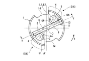
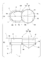
- FIG. 5A is an enlarged plan view as viewed in the Z direction in FIG. 4, and FIG. 5B is an enlarged view around the opening of the pin hole in FIG. 4.
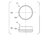
- top view, (b) front view, (c) side view of the fixing member in the embodiment shown in FIG. It is the (a) top view and (b) side view of the auxiliary member in embodiment shown in FIG.
- FIGS. 1 to 7 show an embodiment of the present invention, and this embodiment is a case where the present invention is applied to the above-described expanded bit.
- the tool body 1 is a device of such an enlarged bit, and has a substantially multi-stage cylindrical shape with an axis O as the center, and its rear end (right side in FIG. 1) is The shank portion 1A has the smallest diameter.
- the down-the-hole hammer H connected to the shank portion 1A gives a striking force to the tool body 1 toward the front end side in the direction of the axis O, and is connected to the down-the-hole hammer H via a drilling rod (not shown).
- a drilling hole is formed by excavating the ground (bedrock) or the like by applying a rotational force around the axis O in the tool rotation direction T and a thrust toward the tip side in the axis O direction from a drilling device not shown.
- a step portion 1B having the largest diameter is formed on the distal end side (left side in FIG. 1) of the shank portion 1A of the tool body 1, and the tool body 1 is formed in a columnar shape having a constant outer diameter on the distal end side of the step portion 1B. Is formed.
- a casing pipe P having an inner diameter slightly larger than that of the step portion 1B is disposed on the outer periphery of the tool body 1, and the tool body 1 on the tip side of the step portion 1B is disposed at the tip of the casing pipe P.
- a casing top Q having an inner diameter slightly larger than the outer diameter is attached.
- the stepped portion 1B comes into contact with the rear end of the casing top Q to transmit the thrust and striking force toward the front end side in the axis O direction, whereby the casing pipe P is inserted into the excavation hole formed by the excavation tool.
- the tip of the tool body 1 is positioned at the tip side of the casing top Q with the stepped portion 1B in contact with the rear end of the casing top Q as described above.
- a recess 2 is formed in the surface and the outer peripheral surface.
- the recess 2 includes a bottom surface 2A perpendicular to the axis O facing the tip side of the tool body 1, a flat wall surface 2B facing the tool rotation direction T extending parallel to the axis O from the bottom surface 2A to the tip surface of the tool body 1, and the tool.
- the corner portion 2D which has a flat wall surface 2C facing the outer peripheral side of the main body 1 and intersects these wall surfaces 2B, 2C, is formed in a concave cylindrical surface shape having a center line parallel to the axis O.
- two such recesses 2 are formed with 180 ° rotational symmetry with respect to the axis O.
- the mounting hole 3 in the present embodiment is formed from the bottom surface 2A of these recesses 2 toward the rear end side.
- the mounting hole 3 is formed in a circular shape with a constant inner diameter centering on a hole center line L1 that is parallel to the axis O and eccentric from the axis O toward the outer peripheral side of the tool body 1.
- the hole center line L1 is arranged coaxially with the center line of the concave cylindrical surface formed by the corner 2D of the recess 2 and the inner diameter (diameter) of the mounting hole 3 is formed by the corner 2D. It is slightly smaller than the diameter of the concave cylindrical surface.
- the attachment member 5 is detachably attached to the tool body 1 with the attachment shaft portion 4 inserted into the attachment hole portion 3.
- the attachment member 5 is a bit head of a diameter-expanding bit
- the excavation part 6 is integrally formed at the tip of the attachment shaft part 4.
- a hard tip 7 made of a cemented carbide or the like having a hardness higher than that of the tool body 1 made of steel or the mounting member 5 is embedded in the tip face between the tip face of the excavating portion 6 and the recess 2 of the tool body 1. The ground is crushed by these hard tips 7 and excavation is performed.
- the mounting shaft portion 4 has a cylindrical shaft shape with the shaft portion center line L2 as the center, and is formed so that its outer diameter is slightly smaller than the inner diameter of the mounting hole portion 3, and its length is the mounting length It is formed so as to be substantially equal to the depth of the hole 3. Accordingly, the mounting shaft portion 4 is slidably fitted into the mounting hole portion 3 and inserted so that the shaft portion center line L2 is coaxial with the hole portion center line L1, and the rear end surface thereof is on the bottom surface of the mounting hole portion 3. When it comes into contact, the rear end surface of the excavation part 6 comes into contact with the bottom surface 2 ⁇ / b> A of the recess 2. Thus, the attachment member 5 is rotatable around the hole center line L1 in the inserted state where the attachment shaft portion 4 is inserted into the attachment hole portion 3.
- the excavation part 6 has two flat side surfaces that are closer to each other toward the mounting shaft part 4 at an angle smaller than the angle formed by the wall surfaces 2B and 2C of the recess 2 as shown in FIG.
- These side surfaces are formed to be parallel to the shaft center line L2, that is, to be parallel to the hole center line L1 and the axis O of the tool body 1 in the inserted state.
- the side surface of the convex cylindrical surface on the mounting shaft portion 4 side is a cylindrical surface centered on the shaft center line L2, and the radius thereof is slightly smaller than the radius of the concave cylindrical surface formed by the corner portion 2D of the concave portion 2.
- the side surface is configured to be slidable to the corner portion 2D in the inserted state.
- the attachment member 5 rotates around the hole center line L1 to the opposite side of the tool rotation direction T by the resistance from the ground, and the axis O As shown in FIG. 2, when the flat side surface of the excavation part 6 directed to the opposite side of the tool rotation direction T comes into contact with the wall surface 2B of the recess 2 facing the tool rotation direction T as shown in FIG. Positioned.
- the side surface of the convex cylindrical surface opposite to the mounting shaft portion 4 of the excavation portion 6 is located on a cylindrical surface having a larger outer diameter than the casing pipe P with the axis O of the tool body 1 as the center, An excavation hole into which the casing pipe P can be inserted is formed by the hard tip 7 disposed on the tip side.
- the attachment member 5 rotates around the hole center line L1 toward the tool rotation direction T due to the resistance from the ground.
- the radius from O decreases and the flat side surface of the excavation part 6 directed to the inner peripheral side of the tool main body 1 is positioned when it comes into contact with the wall surface 2C of the recess 2 facing the outer peripheral side of the tool main body 1.
- the excavation part 6 is accommodated in a cylindrical surface having an outer diameter equal to the outer diameter of the column formed by the portion on the tip side of the step part 1B of the tool body 1, and the attachment member 5 together with the down-the-hole hammer H and the excavation rod.
- the tool body 1 can be retracted to the rear end side in the axis O direction and pulled out from the casing pipe P.
- the outer peripheral surface of the mounting shaft portion 4 of the mounting member 5 is along a virtual plane orthogonal to the shaft center line L2, that is, a virtual plane A orthogonal to the hole center line L1 in the inserted state.
- a concave groove 4A is formed.
- This concave groove 4A is formed on the side surface side of the convex cylindrical surface on the mounting shaft portion 4 side of the excavation portion 6 when viewed from the direction of the shaft portion center line L2.
- the cross section along the virtual plane A is formed in an L shape.
- the bent portion of the L shape is formed in a convex arc shape centering on the shaft center line L2 connected to the linearly extending portions on both sides thereof.
- the groove 4A is formed in a half-oval shape extending in the direction of the shaft center line L2 in the cross section along the shaft center line L2, as shown in FIG.
- a pin hole 8 is formed in the tool body 1 along a virtual plane A that is orthogonal to the hole center line L1 in the insertion state.
- the pin hole 8 has a circular cross section, and is in contact with the inner peripheral surface of the two mounting holes 3 formed rotationally symmetrical by 180 ° from the opposite side of the tool rotation direction T and is orthogonal to the axis O.
- the tangent to be made is the pin hole center line C, and penetrates through the tool body 1 so as to open on both sides of the outer peripheral surface which is the outer surface of the tool body 1. Therefore, the pin hole 8 is a portion where the pin hole center line C is in contact with the inner peripheral surface of the mounting hole portion 3 and is partially opened on the inner peripheral surface of the mounting hole portion 3.
- the radius of the pin hole 8 is substantially equal to the depth from the outer peripheral surface of the mounting shaft portion 4 to the groove bottom of the concave groove 4A at the portion in contact with the inner peripheral surfaces of the two mounting hole portions 3.
- the radius of the pin hole 8 on the outer peripheral surface of the tool body 1 (the lower left opening in FIG. 3; the lower opening in FIG. 4) is one step smaller, while the other The opening (the opening on the upper right side in FIG. 3; the opening on the upper side in FIG. 4) opens to the outer peripheral surface of the tool body 1 with the same radius except for the locking portion 11 described later.
- a cylindrical shaft-shaped locking pin 9 having an outer diameter slightly smaller than the inner diameter of the other opening of the pin hole 8 is inserted into the pin hole 8, and the mounting member inserted into the mounting hole 3. 5 is locked in the recessed groove 4A of the mounting shaft portion 4, and one end face of the locking pin 9 is brought into contact with the step portion formed on the one opening side which has a small diameter. .
- the other opening portion having a diameter one step larger than the one opening portion of the pin hole 8 is brought into contact with the other end surface of the locking pin 9 so that the locking pin 9 is interposed between the one opening portion.
- a fixing member 10 that locks in the pin hole center line C direction is attached, and a locking portion 11 that locks the fixing member 10 itself in the pin hole center line C direction is formed.
- a recess 12 communicating with the other opening of the pin hole 8 is formed on the outer peripheral surface of the tool body 1 adjacent to the other opening of the pin hole 8. Is provided with an auxiliary member 13 for maintaining the locking state between the fixing member 10 and the locking portion 11.
- the recess 12 is formed so as to communicate with the rear end side in the axis O direction of the other opening of the pin hole 8 as shown in FIGS.
- the recess 12 has an extension part 12A extending to the rear end side with a width equal to the diameter of the circle formed by the other opening part, and a rear side of the extension part 12A from the pin hole center line C in the direction of the axis O.
- a circular portion 12B having a diameter larger than that of the pin hole 8 having a center on a straight line extending to the end side is provided.
- the distance between the center of the circular portion 12B and the pin hole center line C is set slightly larger than the sum of the radius of the circular portion 12B and the radius of the pin hole 8.
- a groove is formed in the inner peripheral portion of the pin hole 8 and the recess 12 with a slight space between the outer peripheral surface of the tool body 1.
- the groove formed in the inner peripheral portion of the pin hole 8 is the locking portion 11 in the present embodiment.
- the groove formed in the inner periphery of the circular portion 12B in the recess 12 is a recess-side locking portion 12C in the present embodiment, and the groove formed in the extension portion 12A is a slide in the present embodiment.
- a groove 12D is formed.
- the locking portion 11, the recess-side locking portion 12C, and the slide groove 12D are formed along one imaginary plane orthogonal to the pin hole center line C, that is, facing the pin hole center line C direction.
- the two groove wall surfaces facing each other are formed flush with each other by the locking portion 11, the recess-side locking portion 12C, and the slide groove 12D.
- the two groove wall surfaces are formed perpendicular to the pin hole center line C, and the pin hole 8 between the groove wall surfaces and the groove bottom surface facing the inside of the recess 12 are perpendicular to the groove wall surface, that is, the pin hole. It is formed parallel to the center line C.
- the cross section along the pin hole center line C is formed in a rectangular shape in the locking portion 11, the recess-side locking portion 12C, and the slide groove 12D.
- the groove depth formed by the locking portion 11, the recess-side locking portion 12C, and the slide groove 12D that is, from the inner periphery of the pin hole 8 and the extending portion 12A of the recess 12 and the circular portion 12B, is described above.
- the depth to the bottom surface of the groove is formed so that the locking portion 11 and the slide groove 12D have the same constant depth, whereas the recess-side locking portion 12C It is formed to have a constant groove depth shallower than the groove depth of the slide groove 12D.
- the fixing member 10 to be locked to the locking portion 11 is substantially oval in a plan view (FIG. 6A) as shown in FIG. 6 by a rigid body such as steel like the tool body 1 and the like.
- the projecting end of one of the two oval semicircles is notched in a concave arc shape. That is, the fixed member 10 is formed in a shape in which the basic shape in plan view is formed by connecting two semicircular straight portions (diameter or chord of a semicircle) with a rectangle, but one of these semicircles (FIG. 6).
- the tip of the right semicircle in (a) (the part where the major axis of the ellipse connecting the centers of the two semicircles intersects the circumference of one semicircle) is formed in a concave arc shape.
- the outer peripheral surface of the fixing member 10 includes the first and second cylindrical surfaces 10a and 10b corresponding to the two semicircles in the plan view, the two planes connecting these, and the first cylindrical surface 10a. And a concave cylindrical surface 10c formed by cutting out the protruding end portion.
- the fixing member 10 has a flange portion 10A formed on the bottom surface (the right surface in FIG. 6B, the lower surface in FIG. 6C) of the side surface.
- the flange portion 10A has a thickness from the bottom surface of the fixing member 10 slightly smaller than the groove width between the two groove wall surfaces of the groove formed by the locking portion 11 and the slide groove 12D, and is engaged from the side surface.
- the stopper 11 and the slide groove 12D are formed in a rectangular shape with a constant protrusion amount equal to the groove depth.
- the flange portion 10A has the entire circumference of the other semicircle (corresponding to the left semicircle in FIG. 6A, corresponding to the second cylindrical surface 10b) of the two oval semicircles that the fixing member 10 makes in plan view. It extends over the part connected by the rectangle and reaches the one semicircle (corresponding to the first cylindrical surface 10a) (to both ends of the first cylindrical surface 10a).
- the fixing member 10 is on the other semicircle (second cylindrical surface 10b) on the upper surface (the left surface in FIG. 6B, the upper surface in FIG. 6C) from the flange portion 10A. ) Is slightly smaller than the radius of the pin hole 8, and the radius of the one semicircle (first cylindrical surface 10a) is slightly smaller than the radius of the circular portion 12B of the recess 12.
- the radius of the concave arc (concave cylindrical surface 10c) that cuts out one of the semicircles (first cylindrical surface 10a) is formed to be equal to the radius of the circular portion 12B.
- the length in the long axis direction formed by the fixing member 10 including the flange portion 10 ⁇ / b> A is set slightly smaller than the diameter of the circular portion 12 ⁇ / b> B of the recess 12.
- a fixing member side locking portion 10B is formed on the bottom surface side of the concave cylindrical surface 10c cut out in the concave arc shape of the one semicircle (first cylindrical surface 10a) of the fixing member 10. Yes.
- locking part 10B cut out the concave cylindrical surface 10c notched in the said concave arc shape of the fixing member 10 from the bottom face of the fixing member 10 in the cross-section L-shape along this concave arc. It is a concave groove, and the width from the bottom surface of the fixing member 10 and the groove depth from the concave cylindrical surface 10c cut out in the concave arc shape of the fixing member 10 are the width and the groove depth of the recess side locking portion 12C. It is formed to be equal to the height.
- the fixing member 10 formed in this way has a recess 12 with its bottom surface facing the inner peripheral side of the tool body 1 and with the other semicircle (second cylindrical surface 10b) facing the pin hole 8 side.
- the flange portion 10A coincides with the locking portion 11 and the slide groove 12D in the pin hole center line C direction, the flange portion is slid along the slide groove 12D toward the front end side in the axis O direction. 10A can be locked to the opening of the pin hole 8 by being locked in the direction of the pin hole center line C with the lock part 11 and the slide groove 12D.
- the auxiliary member 13 disposed in the recess 12 formed in this way is formed in a disk shape as shown in FIG. 7 by an elastic body such as a synthetic rubber such as urethane rubber in this embodiment. Yes.
- an elastic body such as a synthetic rubber such as urethane rubber in this embodiment.
- the diameter of the flange portion 13A is substantially equal to the inner diameter of the recess-side locking portion 12C on the upper surface side, and is formed so as to gradually become smaller toward the bottom surface side, and the auxiliary member 13 on the upper surface side than the flange portion 13A.
- the diameter of the side surface is substantially equal to the inner diameter of the circular portion 12B of the recess 12. Therefore, the side surface of the auxiliary member 13 and the flange portion 13A, the side surface of the fixing member 10 that is notched in a concave arc shape (concave cylindrical surface 10c), and the fixing member side locking portion 10B are viewed in the pin hole center line C direction.
- line contact is made in the form of concave and convex arcs that complement each other.
- a supply hole 15 for supplying a fluid such as compressed air sent from the excavating machine side extends along the axis O as shown in FIG. 1 diverges at the tip of 1 and opens at an inclined portion of the bottom surface 2 ⁇ / b> A of the recess 2, and also opens at the bottom surface of the mounting hole 3.
- the attachment shaft portion 4 of the attachment member 5 that is a bit head is inserted into the attachment hole portion 3 of the tool body 1 that is a device, and the excavation portion 6 is accommodated in the concave portion 2, and is engaged with the pin hole 8.
- the attachment member 5 is prevented from coming off by inserting the stop pin 9 and engaging it with the concave groove 4 ⁇ / b> A of the attachment shaft portion 4.
- the auxiliary member 13 which is an elastic body is elastically deformed in the recess 12.
- the flange portion 13A By pushing in, the flange portion 13A expands and comes into close contact with the recess side locking portion 12C and the fixing member side locking portion 10B, and the side surface of the auxiliary member 13 on the upper surface side of the flange portion 13A is recessed.
- the fixing member 10 is prevented from coming off by contacting the inner periphery of the place 12 and the concave arcuate portion (concave cylindrical surface 10 c) of the fixing member 10.
- the excavation tool thus configured is inserted into the casing pipe P with the excavation portion 6 of the mounting member 5 having a reduced diameter.
- the rotational force around the axis O is applied as described above, so that the diameter of the excavated portion 6 is expanded and the thrust toward the tip side in the axis O direction is further increased.
- the striking force is applied, a drilling hole is formed, and the casing pipe P is inserted into the drilling hole.
- the excavation part is reduced in diameter by rotating the tool body 1 in the opposite direction to the tool rotation direction T as described above, and the casing pipe P It can be pulled out and collected.
- the side surfaces of the auxiliary member 13 and the concave cylindrical surface 10c of the fixing member 10 that are notched in an arc shape are viewed in the pin hole center line C direction as described above. Since they are in line contact, the pressing force received by the auxiliary member 13 when the fixing member 10 attempts to move to the rear end side in the slide groove 12D by impact due to impact force during excavation, etc. Can be dispersed. Therefore, it is possible to prevent the soft auxiliary member 13 made of an elastic body from being worn by such pressing force.
- the side surface of the fixing member 10 and the side surface of the auxiliary member 13 that are in contact with each other are formed in an uneven shape that complement each other when viewed in the direction of the pin hole center line C. It is possible to lengthen the contact length with which the members are in contact with each other, to further reduce the pressing force per unit contact length, and to reliably suppress wear of the auxiliary member 13.
- the uneven shape is formed in an uneven arc shape, for example, compared to the case where these side surfaces are in contact with corner portions, the fixing member 10 is applied to the auxiliary member 13.
- the pressing force can be uniformly distributed over the circumferential direction of the concavo-convex arc, thus preventing the pressing force from partially concentrating even in the concavo-convex shape that is in contact, thereby further reliably wearing the auxiliary member 13. It becomes possible to suppress.
- a groove-like recess side locking portion 12 ⁇ / b> C is formed on the inner peripheral portion of the recess 12, and the side surface notched in a concave arc shape that contacts the auxiliary member 13 of the fixing member 10.
- a groove-shaped fixing member side locking portion 10B that is coaxial with the recess side locking portion 12C in a state where the fixing member 10 is locked to the locking portion 11 is formed. Then, the auxiliary member 13 is pushed into the recess 12 so that the flange portion 13A enters and is locked into the recess side locking portion 12C and the fixing member side locking portion 10B. Can be reliably prevented and held in the recess 12.
- the fixing member 10 is formed in an oval plate shape.
- a rectangular portion that connects the two semicircles of the ellipse is arranged in the extending portion 12 ⁇ / b> A of the recess 12 that extends from the other opening of the pin hole 8.
- the fixing member 10 is attached to the opening in a state where rotation around the pin hole center line C is constrained. For this reason, it is possible to prevent a situation in which the fixing member 10 rotates around the pin hole center line C due to impact or vibration during excavation and wears the auxiliary member 13. Stable excavation can be performed over a long period of time.
- the above-described configuration of the present embodiment is a device in which the tool body 1 is rotated around the axis O, in which an impact is applied to the tool body 1 during excavation, and the tool body 1 is rotated around the axis O.
- the mounting hole 3 is opened at a position deviated from O
- the pin hole 8 is opened on the outer peripheral surface of the tool body 1
- the mounting member 5 is formed by the excavating part 6 on which the hard tip 7 is disposed.
- a bit head provided at the tip of the attachment shaft portion 4 which has an enlarged diameter that rotates around the shaft center line L ⁇ b> 2 so that the radius from the axis O of the excavation portion 6 increases or decreases as the tool body 1 rotates. It is effective to apply to a drilling tool such as a bit.
- a concave cylindrical surface 10c having a concave shape (concave arc shape) is formed on the side surface of the fixing member 10, and a convex shape (convex arc shape) matching the concave shape is formed on the side surface of the auxiliary member 13. (Shape) is formed, but the unevenness may be reversed.
- the auxiliary member 13 side has a convex shape as in this embodiment.
- the side surfaces of the auxiliary member 13 and the fixing member 10 that are in contact with each other need only be in line contact when viewed in the pin hole center line C direction.
- the fixing member viewed in the pin hole center line C direction.
- the auxiliary member 13 and the fixing member 10 may be in line contact with each other by a straight line connecting both ends of a portion having a concave shape on the side surface of 10.
- the excavation tool according to the present invention is suitable for a diameter expansion bit and an underreaming bit.
Landscapes
- Engineering & Computer Science (AREA)
- Life Sciences & Earth Sciences (AREA)
- Geology (AREA)
- Mining & Mineral Resources (AREA)
- Mechanical Engineering (AREA)
- Physics & Mathematics (AREA)
- Environmental & Geological Engineering (AREA)
- Fluid Mechanics (AREA)
- General Life Sciences & Earth Sciences (AREA)
- Geochemistry & Mineralogy (AREA)
- Earth Drilling (AREA)
Abstract
この掘削工具は工具本体と取付軸部を備えた取付部材とを有し、取付軸部には凹溝が形成され、工具本体に形成されたピン孔には係止ピンが挿入されて凹溝に係止され、ピン孔の開口部には、係止ピンを抜け止めする固定部材が取り付けられるとともに、この固定部材を係止する係止部が形成され、ピン孔の開口部に連通する凹所には固定部材と係止部との係止状態を維持する補助部材が配設され、補助部材と固定部材との互いに接触する側面同士がピン孔中心線方向に見て線接触している。
Description
本発明は、取付孔部を備えた工具本体と、この取付孔部に挿入される取付軸部を備えて工具本体に着脱可能に装着される取付部材とを有する掘削工具に関する。
本願は、2015年3月23日に、日本に出願された特願2015-058939号に基づき優先権を主張し、その内容をここに援用する。
本願は、2015年3月23日に、日本に出願された特願2015-058939号に基づき優先権を主張し、その内容をここに援用する。
このような掘削工具としては、軸線回りに回転される工具本体(デバイス)先端部の上記軸線から偏心した位置に取付孔部が開口するとともに、この取付孔部に取付軸部が挿入されて工具本体に着脱可能に装着された取付部材(ビットヘッド)の先端には、硬質チップが配設された掘削部が設けられた、いわゆる拡径ビットあるいはアンダーリーミングビットと称されるものが知られている。このような拡径ビットでは、工具本体の回転に伴い取付部材が取付軸部の中心線回りに回転することにより、掘削部の上記軸線からの半径が拡大または縮小する。これにより、拡径した状態で大径の掘削孔を形成することができるとともに、この掘削孔に挿入したケーシングパイプ内から縮径した状態の拡径ビットを引き抜いて回収することができる。
このように取付軸部を取付孔部に挿入して取付部材を工具本体に着脱可能に、しかも取付軸部の中心線回りに回転可能に取り付けるために、例えば特許文献1に記載された掘削工具では、取付軸部の外周面に取付軸部の延在方向に交差する凹溝を形成するとともに、工具本体には取付孔部の延在方向に交差する方向に延びてその一部が取付孔部を貫通するピン孔を形成し、このピン孔に取付軸部の凹溝に係合する係止ピンを挿入している。凹溝は取付軸部の回転軸方向に見てL字状に形成されていて、取付部材は、凹溝がなすL字の範囲で凹溝が係止ピンと係合することにより回転自在とされるとともに抜け止めされ、また係止ピンをピン孔から抜き出すことにより取付部材を工具本体から取り外し可能となる。
また、この特許文献1には、取付部材の取り外し時以外に係止ピンをピン孔に固定しておく手段として、ピン孔の開口部に、剛性体からなり、係止ピンの端面に当接して係止ピンを固定する円板状の固定部材と、この固定部材をピン孔の延在方向に係止して固定する係止部を設けることが提案されている。さらに、この特許文献1には、合成ゴム等の弾性体よりなり、これら固定部材と係止部との係止状態を維持する円板状の補助部材を工具本体に配設することも提案されている。
ここで、工具本体には固定部材がスライド移動されるスライド溝が工具本体の軸線方向に延びるように形成され、このスライド溝の一端に、上記ピン孔が開口するとともに、上記係止部が形成されている。また、スライド溝の他端には固定部材の装入部が設けられていて、この装入部から装入された固定部材がスライド溝の一端にスライド移動されて係止部に係止された後、補助部材が装入部に取り付けられて固定部材を押圧することにより、固定部材の移動が防止されて固定部材と係止部との係止状態が維持される。
ところで、上述した拡径ビットのような掘削工具によって掘削孔を形成する際には、工具本体を軸線回りに回転させる回転力とともに、この軸線方向の先端側に向けた推力と、そして同じく軸線方向先端側に向けた打撃力が工具本体に与えられ、先端部に取り付けられた取付部材の硬質チップにより岩盤等を破砕する。この打撃力による衝撃により、固定部材は工具本体の軸線方向に延びるスライド溝内を先端側と後端側とに激しくスライド移動しようとするが、この固定部材の移動も、上述のように上記補助部材が固定部材を押圧することにより防いでいる。
しかしながら、特許文献1に記載された掘削工具では、上述のように固定部材が円板状であるとともに、補助部材も同じく円板状であって、補助部材は点接触で固定部材を押圧する。このため、上述のように固定部材がスライド溝内を移動しようとしたときに補助部材が受ける押し付け力が1点に集中してしまい、軟質な弾性体よりなる補助部材がこの1点から摩耗するおそれがある。
そして、一旦このような摩耗が生じて固定部材と補助部材の間に隙間があくと、固定部材がこの隙間の中で激しくスライド移動することにより摩耗の進行が速まって隙間が一気に広がり、場合によっては補助部材が装入部から外れて固定部材と係止部との係止状態を維持することができなくなってしまう。また、円板状の補助部材と固定部材の側面同士が点接触する特許文献1に記載された掘削工具では、この点接触した部分以外の側面間に大きな隙間があくことになり、このような隙間に細かい砂等が入り込んでしまうことも補助部材の摩耗の一因となるおそれがあった。
本発明は、このような背景の下になされたもので、このような固定部材による押し付け力が補助部材の1点に集中したり、固定部材と補助部材の側面にあいた間隔部分に砂等が入り込んだりするのを防いで補助部材の摩耗を抑制し、長期の掘削作業でも固定部材と係止部との係止状態を維持して安定した掘削が可能な掘削工具を提供することを目的としている。
上記課題を解決して、このような目的を達成するために、本発明は、取付孔部を備えた工具本体と、上記取付孔部に挿入される取付軸部を備えて上記工具本体に着脱可能に装着される取付部材とを有する掘削工具であって、上記取付軸部の外周面には、該取付軸部の中心線に直交する仮想平面に沿って凹溝が形成されるとともに、上記工具本体には、上記取付孔部に挿入された上記取付軸部の上記仮想平面に沿って該工具本体の外面から延びて部分的に上記取付孔部の内周面に開口するピン孔が形成され、このピン孔には係止ピンが挿入されて、上記取付孔部に挿入された上記取付軸部の上記凹溝に係止させられており、上記工具本体の外面における上記ピン孔の開口部には、上記係止ピンに当接して該係止ピンを抜け止めする固定部材が取り付けられるとともに、この固定部材を上記ピン孔の中心線方向に係止する係止部が形成され、上記ピン孔の開口部に隣接する上記工具本体の外面には、該ピン孔の開口部に連通する凹所が形成されていて、この凹所には、上記固定部材の該凹所に臨む側面に接触可能な側面を有して該固定部材と上記係止部との係止状態を維持する補助部材が配設され、上記補助部材と上記固定部材との互いに接触する側面同士が、上記ピン孔の中心線方向に見て線接触していることを特徴とする。
このように構成された掘削工具においては、特許文献1に記載された掘削工具のように固定部材と補助部材とが1点で点接触することなく、固定部材と係止部との係止状態を維持する補助部材と該固定部材との互いに接触する側面同士が、ピン孔の中心線方向に見て線接触しており、掘削時に固定部材から補助部材が受ける押し付け力を線接触した側面で分散して受け止めることができる。このため、固定部材からの押し付け力によって補助部材の摩耗を抑えることができる。
従って、一旦摩耗が生じることによって固定部材と補助部材との間に生じた隙間が一気に広がるのを防ぐことができ、長期に亙って固定部材と係止部との係止状態を維持して安定した掘削を行うことが可能となる。また、このように補助部材と該固定部材との側面同士が線接触することにより、円板状の補助部材と固定部材の側面同士が点接触する特許文献1に記載された掘削工具のように側面間に生じる隙間も小さくすることができ、このような隙間に細かい砂等が入り込んで摩耗の一因となるのも防ぐことができる。
ここで、上記補助部材と上記固定部材との互いに接触する側面同士は、上記ピン孔の中心線方向に見て直線状に線接触していてもよいが、これらの側面同士をピン孔の中心線方向に見て互いに補完し合う凹凸形状に形成しても良い。すなわち、これらの側面同士の一方が凸形状であって他方がこの凸形状に合致して接触する凹形状に形成することにより、ピン孔の中心線方向に見た上記側面同士の接触長さを長くすることができる。その結果、掘削時に固定部材から補助部材が受ける押し付け力を単位接触長さ当たりでより小さく分散して、補助部材に摩耗が生じるのをより確実に抑えることができる。
また、上記補助部材と上記固定部材との互いに接触する側面同士を、上記ピン孔の中心線方向に見て相互に補完し合う凹凸円弧形状に形成しても良い。これにより、固定部材から補助部材が受ける押し付け力を、この凹凸円弧の周方向に均一に分散させることができる。このため、凹凸形状の中でも部分的に押し付け力が集中する箇所が生じるのを防いで、一層確実に補助部材の摩耗を抑制することができる。
一方、特許文献1に記載された掘削工具では、装入部の内周面にリング状溝が形成されるとともに、補助部材にはフランジ状の爪部が形成され、この爪部がリング状溝に係合するように弾性体よりなる補助部材を圧入することにより装入部に抜け止めして固定しているが、リング状溝が形成されることのない固定部材の側面と対向する部分では、補助部材は抜け止めされることはない。そこで、上記構成の掘削工具においては、上記固定部材の上記凹所に臨む側面に、上記補助部材を上記ピン孔の中心線方向に係止する、例えば上記リング状溝を延長した溝部のような固定部材側係止部を形成しても良い。これにより、補助部材の抜け外れを確実に防止することができる。
さらに、特許文献1に記載された掘削工具では、上述のように固定部材が円板状であるので、掘削時の振動や上記衝撃によりピン孔開口部のスライド溝内で回転してしまい、これによっても補助部材の摩耗が促進されるおそれがあった。そこで、上記構成の掘削工具においては、上記固定部材を、上記ピン孔の中心線回りの回転が拘束されるようにして該ピン孔の開口部に取り付けても良い。これにより、このような固定部材の回転による補助部材の摩耗も防止することができる。
従って、これらの構成は、上記工具本体が、軸線回りに回転されるデバイスであって、先端部の上記軸線から偏心した位置に上記取付孔部が開口するとともに、上記ピン孔は上記工具本体の外周面に開口しており、上記取付部材は、硬質チップが配設された掘削部が上記取付軸部の先端に設けられたビットヘッドであって、上記工具本体の回転に伴い上記掘削部の上記軸線からの半径が拡縮径するように上記取付軸部の中心線回りに回転する、上述した拡径ビットのような掘削工具に適用しても良い。これにより、軸線方向先端側への打撃力による衝撃に起因して補助部材が摩耗するのを防ぐことができるので、本発明の構成は、上述した拡径ビットのような掘削工具により好適である。
以上説明したように、本発明によれば、長期の掘削作業でも補助部材の摩耗を抑えることができて固定部材と係止部との係止状態を維持することができ、安定した掘削を行うことが可能となる。
図1ないし図7は、本発明の一実施形態を示すものであって、この実施形態は本発明を上述した拡径ビットに適用した場合のものである。本実施形態において、工具本体1は、このような拡径ビットのデバイスであって、軸線Oを中心とした外形略多段の円柱状をなしており、その後端部(図1における右側部分)は最も小径のシャンク部1Aとされている。
このような掘削工具は、上記シャンク部1Aに連結されたダウンザホールハンマHによって工具本体1に軸線O方向先端側への打撃力が与えられるとともに、このダウンザホールハンマHに図示されない掘削ロッドを介して連結された同じく図示されない掘削装置から工具回転方向Tへの軸線O回りの回転力と軸線O方向先端側への推力が与えられることにより、地盤(岩盤)等を掘削して掘削孔を形成する。
工具本体1のシャンク部1Aの先端側(図1において左側)には最も大径の段部1Bが形成されるとともに、この段部1Bよりも先端側において工具本体1は一定外径の円柱状に形成されている。また、工具本体1の外周には、段部1Bよりも僅かに大きな内径を有するケーシングパイプPが配設されるとともに、このケーシングパイプPの先端には、段部1Bより先端側の工具本体1の外径よりも僅かに大きな内径のケーシングトップQが取り付けられている。このケーシングトップQの後端に段部1Bが当接して軸線O方向先端側への推力と打撃力が伝えられることにより、掘削工具によって形成された掘削孔にケーシングパイプPが挿入されてゆく。
工具本体1の先端部には、上述のようにケーシングトップQの後端に段部1Bが当接した状態で、このケーシングトップQよりも先端側に位置するように、該工具本体1の先端面と外周面とに開口する凹部2が形成されている。凹部2は、工具本体1の先端側を向く軸線Oに垂直な底面2Aと、この底面2Aから工具本体1の先端面にかけて軸線Oに平行に延びる工具回転方向Tを向く平坦な壁面2Bと工具本体1の外周側を向く平坦な壁面2Cとを有し、これらの壁面2B、2Cが交差する隅角部2Dは、軸線Oに平行な中心線を有する凹円筒面状に形成されている。本実施形態では、このような凹部2が軸線Oに関して180°回転対称に2つ形成されている。
さらに、これらの凹部2の底面2Aから後端側に向けては、本実施形態における取付孔部3が形成されている。取付孔部3は、軸線Oに平行で軸線Oから工具本体1の外周側に偏心した孔部中心線L1を中心とした一定内径の断面円形に形成されている。この孔部中心線L1は、凹部2の上記隅角部2Dがなす凹円筒面の中心線と同軸に配置されるとともに、取付孔部3の内径(直径)は、この隅角部2Dがなす凹円筒面の直径よりも僅かに小さい。
取付部材5は、このような取付孔部3に取付軸部4が挿入されて工具本体1に着脱可能に装着される。取付部材5は、本実施形態では拡径ビットのビットヘッドであり、上記取付軸部4の先端に掘削部6が一体に形成されて構成されている。この掘削部6の先端面と、工具本体1の凹部2の間の先端面には、鋼材等からなる工具本体1や取付部材5よりも高硬度の超硬合金等からなる硬質チップ7が埋め込まれて多数配設されており、これらの硬質チップ7により地盤が破砕されて掘削が行われる。
取付軸部4は、軸部中心線L2を中心とした円柱軸状であって、その外径が取付孔部3の内径よりも僅かに小さくなるように形成されるとともに、その長さは取付孔部3の深さと略等しくなるように形成されている。従って、この取付軸部4は取付孔部3に摺動可能に嵌め込まれて軸部中心線L2が孔部中心線L1と同軸となるように挿入され、その後端面が取付孔部3の底面に当接したところで、掘削部6の後端面が凹部2の底面2Aに当接することになる。こうして取付軸部4を取付孔部3に挿入した挿入状態で取付部材5は孔部中心線L1回りに回転自在とされる。
また、掘削部6は、図2に示すように先端視において、凹部2の壁面2B、2Cがなす角度よりも小さな角度で取付軸部4側に向かうに従い互いに近づく2つの平坦な側面と、これらの側面の間に取付軸部4側と取付軸部4の反対側で延びる2つの凸円筒面状の側面とを備えている。これらの側面は軸部中心線L2と平行、すなわち上記挿入状態において孔部中心線L1および工具本体1の軸線Oと平行となるように形成されている。このうち取付軸部4側の凸円筒面状の側面は軸部中心線L2を中心とした円筒面とされ、その半径は凹部2の隅角部2Dがなす凹円筒面の半径よりも僅かに小さくされており、当該側面は上記挿入状態で隅角部2Dに摺接可能とされている。
従って、この挿入状態において掘削時に工具本体1が工具回転方向Tに回転したときには、地盤からの抵抗によって取付部材5は孔部中心線L1回りに工具回転方向Tの反対側に回転して軸線Oからの半径が拡大し、図2に示したようにこの工具回転方向Tの反対側に向けられた掘削部6の平坦な側面が凹部2の工具回転方向Tを向く壁面2Bに当接したところで位置決めされる。このとき、掘削部6の取付軸部4とは反対側の凸円筒面状の側面は、工具本体1の軸線Oを中心としたケーシングパイプPよりも外径の大きい円筒面上に位置し、その先端側に配設された硬質チップ7によってケーシングパイプPを挿入可能な掘削孔を形成する。
また、掘削終了後に工具本体1を掘削時の工具回転方向Tの反対側に回転させると、地盤からの抵抗によって取付部材5は孔部中心線L1回りに工具回転方向T側に回転して軸線Oからの半径が縮小し、工具本体1の内周側に向けられた掘削部6の平坦な側面が凹部2の工具本体1外周側を向く壁面2Cに当接したところで位置決めされる。このとき、掘削部6は、工具本体1の段部1Bよりも先端側の部分がなす円柱の外径と等しい外径の円筒面内に納められ、上記ダウンザホールハンマHおよび掘削ロッドとともに取付部材5ごと工具本体1を軸線O方向後端側に後退させてケーシングパイプP内から引き抜くことが可能となる。
さらに、このような取付部材5の取付軸部4の外周面には、この軸部中心線L2に直交する仮想平面、すなわち上記挿入状態における孔部中心線L1に直交する仮想平面Aに沿って凹溝4Aが形成されている。この凹溝4Aは、軸部中心線L2方向から見て掘削部6の取付軸部4側の凸円筒面状の側面側に形成されている。本実施形態では図3に示すように仮想平面Aに沿った断面がL字状に形成されている。ただしこのL字の折れ曲がる部分は、その両側の直線状に延びる部分に接続する軸部中心線L2を中心とした凸円弧状に形成されている。また、凹溝4Aは、軸部中心線L2に沿った断面では、図1に示したように該軸部中心線L2方向に延びる半割長円状に形成されている。
一方、工具本体1には、同じく上記挿入状態における孔部中心線L1に直交する仮想平面Aに沿ってピン孔8が形成されている。このピン孔8は、本実施形態では断面円形のものであって、180°回転対称形成された2つの取付孔部3の内周面に工具回転方向Tの反対側から接して軸線Oに直交する接線をピン孔中心線Cとし、工具本体1の外面である外周面の両側に開口するように該工具本体1を貫通している。従って、このピン孔8は、ピン孔中心線Cが取付孔部3の内周面に接する部分で、この取付孔部3の内周面に部分的に開口する。
また、ピン孔8の半径は、2つの取付孔部3の内周面に接する部分では、取付軸部4の外周面から凹溝4Aの溝底までの深さと略等しくされている。ただし、このピン孔8の工具本体1外周面への一方の開口部(図3における左下側の開口部。図4においては下側の開口部)では半径が一段小径とされるとともに、他方の開口部(図3における右上側の開口部。図4においては上側の開口部)は後述する係止部11を除いてそのままの半径で工具本体1の外周面に開口している。そして、このピン孔8には、ピン孔8の他方の開口部の内径よりも僅かに小さな外径の円柱軸状の係止ピン9が挿入されて、取付孔部3に挿入された取付部材5の取付軸部4の凹溝4Aに係止されるとともに、一段小径とされた上記一方の開口部側に形成される段部に係止ピン9の一方の端面が当接させられている。
さらに、ピン孔8の一方の開口部より一段大径とされた他方の開口部には、係止ピン9の他方の端面に当接して一方の開口部との間で該係止ピン9をピン孔中心線C方向に係止する固定部材10が取り付けられるとともに、この固定部材10自体をピン孔中心線C方向に係止する係止部11が形成されている。さらにまた、このピン孔8の他方の開口部に隣接する工具本体1の外周面には、該ピン孔8の他方の開口部に連通する凹所12が形成されており、この凹所12には、固定部材10と係止部11との係止状態を維持する補助部材13が配設されている。
ここで、凹所12は、本実施形態では図1および図5に示したようにピン孔8の他方の開口部の軸線O方向後端側に連通するように形成されている。凹所12は、この他方の開口部がなす円の直径と等しい幅で後端側に延びる延出部12Aと、この延出部12Aの後端側においてピン孔中心線Cから軸線O方向後端側に延びる直線上に中心を有するピン孔8よりも大径の円形部12Bとを備えている。この円形部12Bの中心とピン孔中心線Cとの間隔は、円形部12Bの半径とピン孔8の半径との和よりも僅かに大きく設定されている。
また、これらピン孔8と凹所12の内周部には、工具本体1の外周面との間に僅かな間隔をあけて溝が形成されている。このうちピン孔8の内周部に形成された溝が本実施形態における上記係止部11とされている。さらに、凹所12のうち円形部12Bの内周に形成された溝は本実施形態では凹所側係止部12Cとされるとともに、延出部12Aに形成された溝は本実施形態におけるスライド溝12Dとされる。
これら係止部11、凹所側係止部12C、およびスライド溝12Dは、ピン孔中心線Cに直交する1つの仮想平面に沿うように形成されていて、すなわちピン孔中心線C方向を向いて互いに対向する2つの溝壁面は、それぞれ係止部11、凹所側係止部12C、およびスライド溝12D同士で面一に形成されている。また、これら2つの溝壁面はピン孔中心線Cに垂直に形成されるとともに、これらの溝壁面の間のピン孔8と凹所12の内側を向く溝底面は、溝壁面に垂直すなわちピン孔中心線Cに平行に形成されている。このように、係止部11、凹所側係止部12C、およびスライド溝12Dはピン孔中心線Cに沿った断面が矩形状に形成されている。
なお、これら係止部11、凹所側係止部12C、およびスライド溝12Dがなす溝の溝深さ、すなわちピン孔8と凹所12の延出部12Aおよび円形部12Bの内周から上記溝底面までの深さは、係止部11とスライド溝12Dとで互いに等しい一定の深さとなるように形成されているのに対し、凹所側係止部12Cでは、これら係止部11とスライド溝12Dの溝深さよりも浅い一定の溝深さとなるように形成されている。
このうち、係止部11に係止される上記固定部材10は、工具本体1等と同じく鋼材等の剛性体により、図6に示すように平面視(図6(a))に概略長円形の板状に形成されており、ただしこの長円形の2つの半円のうち一方の半円の突端部は凹円弧状に切り欠かれている。すなわち、固定部材10は、平面視の基本形状が2つの半円の直線部分(半円の直径または弦)を長方形で繋いだ形状に形成されており、ただしこのうち一方の半円(図6(a)における右側の半円)の突端部(2つの半円の中心を結ぶ長円の長軸が一方の半円の円周に交差する部分)が凹円弧状に凹んだ形状に形成されている。このように、固定部材10の外周面は、上記平面視における2つの半円に相当する第1、第2の円筒面10a、10bと、これらを繋ぐ2つの平面と、第1の円筒面10aの突端部を切り欠いて形成された凹円筒面10cとを備える。
また、固定部材10には、その側面の底面(図6(b)における右側の面。図6(c)においては下側の面)側に、フランジ部10Aが形成されている。このフランジ部10Aは、その固定部材10の上記底面からの厚さが係止部11およびスライド溝12Dがなす溝の上記2つの溝壁面の間の溝幅よりも僅かに小さく、上記側面から係止部11とスライド溝12Dの上記溝深さと等しい一定の突出量の断面矩形状に形成されている。フランジ部10Aは、固定部材10が平面視になす長円形の2つの半円のうち他方の半円(図6(a)における左側の半円、第2の円筒面10bに相当)の全周から上記長方形で繋いだ部分に亙って延び、上記一方の半円(第1の円筒面10aに相当)に達するところまで(第1の円筒面10aの両端まで)形成されている。
さらに、このフランジ部10Aよりも上面(図6(b)における左側の面。図6(c)においては上側の面)側において固定部材10は、上記他方の半円(第2の円筒面10b)の半径がピン孔8の半径よりも僅かに小さくなるように形成されるとともに、上記一方の半円(第1の円筒面10a)の半径は凹所12の円形部12Bの半径よりも僅かに小さくなるように形成され、この一方の半円(第1の円筒面10a)を切り欠く上記凹円弧(凹円筒面10c)の半径は円形部12Bの半径と等しくなるように形成されている。また、フランジ部10Aを含めた固定部材10がなす上記長軸方向の長さは凹所12の円形部12Bの直径よりも僅かに小さく設定されている。
さらにまた、固定部材10の上記一方の半円(第1の円筒面10a)の凹円弧状に切り欠かれた凹円筒面10cの底面側には、固定部材側係止部10Bが形成されている。この固定部材側係止部10Bは、固定部材10の上記凹円弧状に切り欠かれた凹円筒面10cを、この凹円弧に沿うように固定部材10の底面から断面L字状に切り欠いた凹溝であり、固定部材10の底面からの幅と固定部材10の上記凹円弧状に切り欠かれた凹円筒面10cからの溝深さは、凹所側係止部12Cの幅と溝深さに等しくなるように形成されている。
従って、このように形成された固定部材10は、その底面を工具本体1の内周側に向けるとともに上記他方の半円(第2の円筒面10b)をピン孔8側に向けて凹所12に挿入することができ、フランジ部10Aがピン孔中心線C方向に係止部11およびスライド溝12Dと一致したところで、スライド溝12Dに沿って軸線O方向先端側にスライドさせることにより、フランジ部10Aを係止部11およびスライド溝12Dとピン孔中心線C方向に係止させてピン孔8の開口部に取り付けることができる。そして、このとき固定部材10の一方の半円(第1の円筒面10a)を切り欠いた凹円弧部分(凹円筒面10c)および固定部材側係止部10Bは凹所12側に臨むように向けられ、凹所12の円形部12Bおよび凹所側係止部12Cと同軸に配置される。
このように形成された凹所12に配設される補助部材13は、本実施形態においてもウレタンゴム等の合成ゴムのような弾性体により、図7に示すように円板状に形成されている。補助部材13の底面側(図7(b)において下側)には、上面側(図7(b)において上側)よりも直径が僅かに大きなフランジ部13Aが形成されている。このフランジ部13Aの直径は上面側で凹所側係止部12Cの内径と略等しく、底面側に向かうに従い漸次小さくなるように形成されるとともに、このフランジ部13Aよりも上面側の補助部材13の側面の直径は凹所12の円形部12Bの内径と略等しくされている。従ってこの補助部材13の側面およびフランジ部13Aと固定部材10の凹円弧状に切り欠かれた側面(凹円筒面10c)および固定部材側係止部10Bとは、ピン孔中心線C方向に見て相互に補完し合う凹凸形状で線接触しており、特に本実施形態では相互に補完し合う凹凸円弧形状で線接触するように形成される。
なお、工具本体1の段部1Bから先端側の外周部には、掘削時に発生する掘削屑を排出するための2つの排出溝14が、2つの凹部2の底面2Aにおいて取付孔部3の工具回転方向T側に開口するように形成されており、その開口部において底面2Aは図1に示すように外周側に向かうに従い軸線O方向後端側に向かうように傾斜している。また、工具本体1内には、上記掘削機械側から送られる圧縮空気等の流体を供給する供給孔15が図1に示すように軸線Oに沿って延びており、この供給孔15は工具本体1の先端部で分岐して凹部2の底面2Aの傾斜した部分に開口するとともに、取付孔部3の底面にも開口している。
このような掘削工具では、ビットヘッドである取付部材5の取付軸部4をデバイスである工具本体1の取付孔部3に挿入して掘削部6を凹部2に収容し、ピン孔8に係止ピン9を挿入して取付軸部4の凹溝4Aに係止することにより、取付部材5が抜け止めされる。
さらに、上述のように凹所12に挿入した固定部材10をスライドさせてピン孔8の開口部の係止部11に係止した後、凹所12に弾性体である補助部材13を弾性変形させつつ押し込むことにより、フランジ部13Aが凹所側係止部12Cと固定部材側係止部10Bに入り込んだところで広がって密着するとともに、フランジ部13Aよりも上面側の補助部材13の側面が凹所12の内周と固定部材10の凹円弧状部分(凹円筒面10c)に接触して固定部材10が抜け止めされる。
さらに、上述のように凹所12に挿入した固定部材10をスライドさせてピン孔8の開口部の係止部11に係止した後、凹所12に弾性体である補助部材13を弾性変形させつつ押し込むことにより、フランジ部13Aが凹所側係止部12Cと固定部材側係止部10Bに入り込んだところで広がって密着するとともに、フランジ部13Aよりも上面側の補助部材13の側面が凹所12の内周と固定部材10の凹円弧状部分(凹円筒面10c)に接触して固定部材10が抜け止めされる。
こうして構成された掘削工具は、取付部材5の掘削部6が縮径した状態でケーシングパイプP内に挿入される。工具本体1の段部1BがケーシングトップQに当接した状態で、上述のように軸線O回りの回転力が与えられることにより掘削部6が拡径し、さらに軸線O方向先端側への推力および打撃力が与えられることにより掘削孔を形成するとともに、この掘削孔にケーシングパイプPを挿入してゆく。また、所定の深さまで掘削孔が形成されてケーシングパイプPが挿入されたら、上述のように工具本体1を工具回転方向Tの反対側に回転させることにより掘削部を縮径し、ケーシングパイプPから引き抜いて回収することができる。
そして、上記構成の掘削工具では、補助部材13と固定部材10の円弧状に切り欠かれた凹円筒面10cとの互いに接触する側面同士が、上述のようにピン孔中心線C方向に見て線接触しているので、掘削時の打撃力等による衝撃によって固定部材10がスライド溝12D内を後端側に移動しようとしたときに補助部材13が受ける押し付け力を、これらの線接触する側面で分散させることができる。従って、このような押し付け力によって弾性体よりなる軟質な補助部材13が摩耗するのを抑制することができる。
このため、補助部材13の摩耗によって固定部材10との間に隙間が生じるのを長期に亙って抑えることができ、このような隙間が固定部材10の移動によって一気に広がるのを防いで固定部材10の係止部11への係止状態を確実に維持し、安定した掘削を行うことが可能となる。また、固定部材10と補助部材13との接触した側面以外の部分の隙間を小さくすることもできるので、このような隙間に細かい砂等が入り込んで補助部材13に摩耗が生じるのも抑制することができる。
さらに、本実施形態では、こうして接触する固定部材10の側面と補助部材13の側面とが、ピン孔中心線C方向に見て相互に補完し合う凹凸形状に形成されているので、これらの側面同士が接触する接触長さを長くすることができて、単位接触長さ当たりの押し付け力をより小さく分散し、確実に補助部材13の摩耗を抑制することができる。しかも、本実施形態では、この凹凸形状が凹凸円弧形状に形成されているので、例えばこれらの側面が角部を有して接触している場合などに比べ、固定部材10による補助部材13への上記押し付け力を凹凸円弧の周方向に亙って均一に分散させることができ、こうして接触した凹凸形状においても押し付け力が部分的に集中するのを防いで、一層確実に補助部材13の摩耗を抑えることが可能となる。
また、本実施形態では、凹所12の内周部に溝状の凹所側係止部12Cが形成されるとともに、固定部材10の補助部材13と接触する凹円弧状に切り欠かれた側面(凹円筒面10c)には、固定部材10を係止部11に係止した状態で凹所側係止部12Cと同軸となる溝状の固定部材側係止部10Bが形成されている。そして、補助部材13は、凹所12に押し込まれることによりフランジ部13Aがこれら凹所側係止部12Cと固定部材側係止部10Bに入り込んで係止されるので、補助部材13の抜け外れを確実に防いで凹所12に保持することが可能となる。
さらに、本実施形態では、固定部材10が長円形の板状に形成されている。固定部材10を係止部11に係止したときに、この長円の2つの半円を繋ぐ長方形状部分が、ピン孔8の他方の開口部から延びる凹所12の延出部12Aに配設されることにより、固定部材10はピン孔中心線C回りの回転が拘束された状態で上記開口部に取り付けられる。このため、掘削時の衝撃や振動などにより固定部材10がピン孔中心線C回りに回転してしまって補助部材13を摩耗させるような事態も防ぐことができるので、本実施形態によれば一層長期に亙って安定した掘削を行うことが可能となる。
従って、本実施形態の上記構成は、このように掘削時に工具本体1に打撃力が与えられて衝撃が生じる、工具本体1が軸線O回りに回転されるデバイスであって、その先端部の軸線Oから偏心した位置に上記取付孔部3が開口するとともに、ピン孔8は工具本体1の外周面に開口しており、上記取付部材5は、硬質チップ7が配設された掘削部6が取付軸部4の先端に設けられたビットヘッドであって、工具本体1の回転に伴い掘削部6の軸線Oからの半径が拡大または縮小するように軸部中心線L2回りに回転する拡径ビットのような掘削工具に適用することが効果的である。
なお、本実施形態では、固定部材10の側面に凹形状(凹円弧形状)となる凹円筒面10cが形成されるとともに、補助部材13の側面にはこの凹形状に合致する凸形状(凸円弧形状)となる部分が形成されているが、凹凸は逆であってもよい。ただし、弾性体よりなる補助部材13の大きさを確保することを考慮すると、本実施形態のように補助部材13側を凸形状とするのが望ましい。また、補助部材13と固定部材10との互いに接触する側面同士はピン孔中心線C方向に見て線接触していればよく、例えば上記実施形態においてピン孔中心線C方向に見た固定部材10の側面が凹形状となる部分の両端を結んだ一直線で補助部材13と固定部材10とが線接触していてもよい。
本発明によれば、補助部材の摩耗を抑制して長期の掘削作業でも固定部材と係止部との係止状態を維持することができる。そのため、本発明に係る掘削工具は、拡径ビットやアンダーリーミングビットに好適である。
1 工具本体
2 凹部
3 取付孔部
4 取付軸部
4A 凹溝
5 取付部材
6 掘削部
7 硬質チップ
8 ピン孔
9 係止ピン
10 固定部材
10A 固定部材10のフランジ部
10B 固定部材側係止部
11 係止部
12 凹所
12C 凹所側係止部
13 補助部材
13A 補助部材13のフランジ部
O 工具本体1の軸線
T 工具回転方向
A 凹溝4Aおよびピン孔8が形成される仮想平面
L1 孔部中心線(取付孔部3の中心線)
L2 軸部中心線(取付軸部4の中心線)
C ピン孔中心線(ピン孔8の中心線)
2 凹部
3 取付孔部
4 取付軸部
4A 凹溝
5 取付部材
6 掘削部
7 硬質チップ
8 ピン孔
9 係止ピン
10 固定部材
10A 固定部材10のフランジ部
10B 固定部材側係止部
11 係止部
12 凹所
12C 凹所側係止部
13 補助部材
13A 補助部材13のフランジ部
O 工具本体1の軸線
T 工具回転方向
A 凹溝4Aおよびピン孔8が形成される仮想平面
L1 孔部中心線(取付孔部3の中心線)
L2 軸部中心線(取付軸部4の中心線)
C ピン孔中心線(ピン孔8の中心線)
Claims (6)
- 取付孔部を備えた工具本体と、上記取付孔部に挿入される取付軸部を備えて上記工具本体に着脱可能に装着される取付部材とを有する掘削工具であって、
上記取付軸部の外周面には、該取付軸部の中心線に直交する仮想平面に沿って凹溝が形成されるとともに、
上記工具本体には、上記取付孔部に挿入された上記取付軸部の上記仮想平面に沿って該工具本体の外面から延びて部分的に上記取付孔部の内周面に開口するピン孔が形成され、
このピン孔には係止ピンが挿入されて、上記取付孔部に挿入された上記取付軸部の上記凹溝に係止させられており、
上記工具本体の外面における上記ピン孔の開口部には、上記係止ピンに当接して該係止ピンを抜け止めする固定部材が取り付けられるとともに、この固定部材を上記ピン孔の中心線方向に係止する係止部が形成され、
上記ピン孔の開口部に隣接する上記工具本体の外面には、該ピン孔の開口部に連通する凹所が形成されていて、
この凹所には、上記固定部材の該凹所に臨む側面に接触可能な側面を有して該固定部材と上記係止部との係止状態を維持する補助部材が配設され、
上記補助部材と上記固定部材との互いに接触する側面同士が、上記ピン孔の中心線方向に見て線接触していることを特徴とする掘削工具。 - 上記補助部材と上記固定部材との互いに接触する側面同士が、上記ピン孔の中心線方向に見て相互に補完し合う凹凸形状に形成されていることを特徴とする請求項1に記載の掘削工具。
- 上記補助部材と上記固定部材との互いに接触する側面同士が、上記ピン孔の中心線方向に見て相互に補完し合う凹凸円弧形状に形成されていることを特徴とする請求項2に記載の掘削工具。
- 上記固定部材の上記凹所に臨む側面には、上記補助部材を上記ピン孔の中心線方向に係止する固定部材側係止部が形成されていることを特徴とする請求項1から請求項3のうちいずれか一項に記載の掘削工具。
- 上記固定部材は、上記ピン孔の中心線回りの回転が拘束されて該ピン孔の開口部に取り付けられていることを特徴とする請求項1から請求項4のうちいずれか一項に記載の掘削工具。
- 上記工具本体は、軸線回りに回転されるデバイスであって、先端部の上記軸線から偏心した位置に上記取付孔部が開口するとともに、上記ピン孔は上記工具本体の外周面に開口しており、
上記取付部材は、硬質チップが配設された掘削部が上記取付軸部の先端に設けられたビットヘッドであって、上記工具本体の回転に伴い上記掘削部の上記軸線からの半径が拡縮径するように上記取付軸部の中心線回りに回転することを特徴とする請求項1から請求項5のうちいずれか一項に記載の掘削工具。
Applications Claiming Priority (2)
| Application Number | Priority Date | Filing Date | Title |
|---|---|---|---|
| JP2015058939A JP6468024B2 (ja) | 2015-03-23 | 2015-03-23 | 掘削工具 |
| JP2015-058939 | 2015-03-23 |
Publications (1)
| Publication Number | Publication Date |
|---|---|
| WO2016152674A1 true WO2016152674A1 (ja) | 2016-09-29 |
Family
ID=56977435
Family Applications (1)
| Application Number | Title | Priority Date | Filing Date |
|---|---|---|---|
| PCT/JP2016/058307 Ceased WO2016152674A1 (ja) | 2015-03-23 | 2016-03-16 | 掘削工具 |
Country Status (2)
| Country | Link |
|---|---|
| JP (1) | JP6468024B2 (ja) |
| WO (1) | WO2016152674A1 (ja) |
Cited By (1)
| Publication number | Priority date | Publication date | Assignee | Title |
|---|---|---|---|---|
| AU2023222859B2 (en) * | 2022-09-07 | 2025-03-27 | Sungbo Industrial Co., Ltd. | Fastening device for different components |
Citations (3)
| Publication number | Priority date | Publication date | Assignee | Title |
|---|---|---|---|---|
| JP2003082971A (ja) * | 2001-09-13 | 2003-03-19 | Mitsubishi Materials Corp | 掘削工具 |
| JP4957440B2 (ja) * | 2007-08-06 | 2012-06-20 | 三菱マテリアル株式会社 | 掘削工具 |
| JP2013011078A (ja) * | 2011-06-28 | 2013-01-17 | Aoba-Kenki Co Ltd | 掘削装置及び掘削工法 |
Family Cites Families (3)
| Publication number | Priority date | Publication date | Assignee | Title |
|---|---|---|---|---|
| KR100685386B1 (ko) * | 2004-09-03 | 2007-02-22 | 임병덕 | 인-라인 확장 윙을 갖는 시추공 굴착장치 및 그 구동방법 |
| KR101244782B1 (ko) * | 2010-03-11 | 2013-03-18 | (주)탑드릴 | 지반 굴착 해머용 확경 비트 |
| UA108940C2 (uk) * | 2011-07-05 | 2015-06-25 | Утримуючий пристрій, утримуюча система між охоплюючим компонентом і охоплюваним компонентом, охоплюючий компонент і охоплюваний компонент для екскаваторів і їм подібних машин |
-
2015
- 2015-03-23 JP JP2015058939A patent/JP6468024B2/ja active Active
-
2016
- 2016-03-16 WO PCT/JP2016/058307 patent/WO2016152674A1/ja not_active Ceased
Patent Citations (3)
| Publication number | Priority date | Publication date | Assignee | Title |
|---|---|---|---|---|
| JP2003082971A (ja) * | 2001-09-13 | 2003-03-19 | Mitsubishi Materials Corp | 掘削工具 |
| JP4957440B2 (ja) * | 2007-08-06 | 2012-06-20 | 三菱マテリアル株式会社 | 掘削工具 |
| JP2013011078A (ja) * | 2011-06-28 | 2013-01-17 | Aoba-Kenki Co Ltd | 掘削装置及び掘削工法 |
Cited By (1)
| Publication number | Priority date | Publication date | Assignee | Title |
|---|---|---|---|---|
| AU2023222859B2 (en) * | 2022-09-07 | 2025-03-27 | Sungbo Industrial Co., Ltd. | Fastening device for different components |
Also Published As
| Publication number | Publication date |
|---|---|
| JP2016176300A (ja) | 2016-10-06 |
| JP6468024B2 (ja) | 2019-02-13 |
Similar Documents
| Publication | Publication Date | Title |
|---|---|---|
| CN104797383B (zh) | 用于敲击式锚栓的安装工具 | |
| JP4957440B2 (ja) | 掘削工具 | |
| EP3184729B1 (en) | Excavation tool | |
| EP2787163B1 (en) | Excavation tool | |
| KR20160138034A (ko) | 굴삭 공구 | |
| EP3225857B1 (en) | Improved bit retainer | |
| JP6468024B2 (ja) | 掘削工具 | |
| WO2018055728A1 (ja) | 掘削工具 | |
| CN109982814A (zh) | 撞击装置 | |
| JP2018062788A (ja) | 掘削工具 | |
| JP6512012B2 (ja) | 掘削工具 | |
| JP6447741B2 (ja) | 掘削工具 | |
| JP2016176301A (ja) | 掘削工具 | |
| JP2018119345A (ja) | 掘削工具 | |
| KR102044131B1 (ko) | 사용이 편리한 암반파쇄공구 | |
| JP2018044285A (ja) | 掘削工具 | |
| JP6759726B2 (ja) | 掘削工具 | |
| JP3994706B2 (ja) | 掘削工具 | |
| JP2019183624A (ja) | 掘削工具 | |
| WO2017057716A1 (ja) | 掘削工具 | |
| JP2001040976A (ja) | 掘削工具 | |
| JP2017218743A (ja) | 掘削工具 | |
| JPH11200751A (ja) | 掘削工具および掘削工法 |
Legal Events
| Date | Code | Title | Description |
|---|---|---|---|
| 121 | Ep: the epo has been informed by wipo that ep was designated in this application |
Ref document number: 16768577 Country of ref document: EP Kind code of ref document: A1 |
|
| NENP | Non-entry into the national phase |
Ref country code: DE |
|
| 122 | Ep: pct application non-entry in european phase |
Ref document number: 16768577 Country of ref document: EP Kind code of ref document: A1 |